GUIDELINES FOR PRACTICAL ASSESSMENT TASKS PAT ENGLISH.pdf · Engineering Graphics and Design 4...
22
Copyright reserved Please turn over ENGINEERING GRAPHICS AND DESIGN GUIDELINES FOR PRACTICAL ASSESSMENT TASKS 2011 These guidelines consist 22 pages.
Transcript of GUIDELINES FOR PRACTICAL ASSESSMENT TASKS PAT ENGLISH.pdf · Engineering Graphics and Design 4...

Engineering Graphics and Design 1 DBE/PAT 2011 NSC
Copyright reserved Please turn over
ENGINEERING GRAPHICS AND DESIGN
GUIDELINES FOR
PRACTICAL ASSESSMENT TASKS
2011
These guidelines consist 22 pages.

Engineering Graphics and Design 2 DBE/PAT 2011 NSC
Copyright reserved Please turn over
TABLE OF CONTENTS INTRODUCTION
SECTION A (Teacher Guidelines)
1. The structure of the PAT
Elements that make up the final PAT mark
2. Administration of the PAT
3. Assessment and moderation of the PAT
3.1 Assessment 3.2 Moderation 3.3 Declaration of Authenticity
SECTION B (The Learner Tasks) PAT 1 A Civil Design Project
PAT 2 A Mechanical Design Project A SIMPLIFIED RUBRIC FOR THE ALLOCATION OF MARKS ANNEXURE A Rubric for assessing the design process ANNEXURE B Rubric for assessing the correctness of drawings ANNEXURE C Rubric for assessing drawing-method skills and presentation ANNEXURE D
A rubric for assessing CAD drawing skills 2011 SUMMATIVE ASSESSMENT DECLARATION OF AUTHENTICITY

Engineering Graphics and Design 3 DBE/PAT 2011 NSC
Copyright reserved Please turn over
INTRODUCTION The seventeen National Curriculum Statement subjects which contain a practical component all include a Practical Assessment Task (PAT). These subjects are: AGRICULTURE: Agricultural Management Practices, Agricultural Technology ARTS: Dance Studies, Design, Dramatic Arts, Music, Visual Arts HSS: Life Orientation SCIENCES: Computer Applications Technology, Information Technology SERVICES: Consumer Studies, Hospitality Studies, Tourism TECHNOLOGY: Civil Technology, Electrical Technology, Engineering Graphics and Design,
Mechanical Technology A PAT allows the teacher to directly and systematically observe applied competence. The PAT comprises the application of knowledge and values and the demonstration and performance of skills particular to that subject and counts 25% (i.e. 100 marks) of the total promotion/certification mark out of 400 for Engineering Graphics and Design. The Grade 12 PAT is implemented across the first three terms of the school year and should be undertaken as one extended task, which is broken down into different phases or a series of smaller activities that make up the PAT. The planning and execution of the PAT differ from subject to subject. SECTION A is the guidelines to the teacher describing the structure and the administration of the PAT, while SECTION B contains the tasks and the assessment tools for both the learner and the teacher.

Engineering Graphics and Design 4 DBE/PAT 2011 NSC
Copyright reserved Please turn over
SECTION A (Teacher Guidelines) 1. The structure of the Practical Assessment Task (PAT) for EGD A Practical Assessment Task is designed to develop a learner's ability to integrate and apply knowledge and to demonstrate acquired levels of skills, and competency. With the inclusion of the PAT into Engineering Graphics and Design, the learner is given an opportunity to apply acquired knowledge, skills and values in a creative way through the design process as outlined in LO 2 in the National Curriculum Statement. The learner is given an opportunity to complete the PAT in an environment which is more conducive to the creative processes. This environment should therefore provide the learner with easier access to, and a wider variety of, resource material than would be available in a formal examination. The various components of the Engineering Graphics and Design PAT gives the learner an opportunity to demonstrate the level of drawing skill that has been attained in all the appropriate drawing methods through the presentation of the required drawings. Each Engineering Graphics and Design Practical Assessment Task consists of two parts: Part A: The design process Part B: Required presentation drawings Three assessable components, namely the design process, drawing presentation and drawing method, are covered within the two parts of both PATs. Part A of both PATs focuses on LO 2 and requires that the learner demonstrates a clear understanding of, and is able to apply, the design process. As part of the design process the learner must be able to: Identify the problem and formulate a design brief with specifications and constraints Conduct and make use of relevant external research in an appropriate way Generate a number of own ideas/concepts/solutions analytically and graphically Select a final solution(s) that demonstrates a clear understanding of the design brief within
the context of the specifications and constraints Develop presentation drawings of the selected solution(s) Provide clear evidence of continuous self-evaluation during the development of the PAT. Part B of both PATs focuses on LO 3 and LO 4 and requires that the learner demonstrates and provides evidence of a high level of knowledge and understanding of the concepts and content of Engineering Graphics and Design through the presentation of orthographic drawings and pictorial drawings. Part A and Part B of both PATs also give the learner the opportunity to demonstrate that a high level of competency and skill has been attained in all the required drawing methods. The methods include: Freehand drawing Instrument drawing Using a CAD (Computer-aided Design/Drawing) system

Engineering Graphics and Design 5 DBE/PAT 2011 NSC
Copyright reserved Please turn over
Two Practical Assessment Tasks (PATs) are included in this document. PAT 1 is a design task in the context of a civil drawing that contains electrical features. PAT 2 is a design task in the context of a mechanical drawing.
Each learner must, with the guidance of the teacher, select ONE of the two PATs contained in this document. Should the learner choose to complete both PATs, only ONE will be considered for summative assessment and promotion purposes. Elements that make up the final PAT mark
ELEMENTS OF THE PRACTICAL ASSESSMENT TASK MARK ELEMENT MARKS
The design process 25 The correctness of the presentation drawings 50 The drawing methods (freehand, instrument and CAD) 25
TOTAL 100 2. Administration of the PAT At the beginning of the academic year, the teacher must ensure that every Grade 12 learner receives a copy of the entire SECTION B of the PAT document, including the assessment criteria (annexure A, B, C and D), the 2011 summative assessment form and the declaration of authenticity form. The selected PAT must be completed during the first three terms. ALL the presentation requirements of the PATs should be completed within 12 to a maximum of 16 hours. However, the completed PAT (part A and part B) must be submitted in time for summative assessment to be done before the commencement of provincial moderation. To ensure that the PAT is completed within the stipulated time, it is essential that the teacher draw up a pace setter for the learners at the beginning of the year. Attached to the pace setter must be target dates for the completion of the different components of the different phases of the PAT. This will help learners to assess their own progress and teachers to set up intervention programmes should they see that the learners are falling behind with their work. It is therefore recommended that the PAT be completed in three phases: Phase 1: Design Process (completed by the end of the 1st term) Phase 2: Presentation Drawings (completed by the end of the 2nd term) Phase 3: Completion of portfolio (before the commencement of moderation in the 3rd term) NOTE: ALL the presentation requirements of the PAT must be completed under controlled
conditions at school, under guidance and supervision from the Engineering Graphics and Design teacher, who must observe the learners' progress at all times.
It is the teacher's responsibility to ensure that each learner's PAT is of an appropriate higher order Grade 12 complexity!
All the completed presentation requirements of the PAT must always be available for monitoring and moderation purposes.

Engineering Graphics and Design 6 DBE/PAT 2011 NSC
Copyright reserved Please turn over
3. Assessment and moderation of the PAT The Practical Assessment Task for Grade 12 is externally set, internally assessed and externally moderated. It is therefore the duty and responsibility of the teacher to administer assessment and record the progress in instances where formal assessment is required. 3.1 Assessment
Frequent developmental feedback is needed to guide and give support to the learner and to ensure that the learner is on the right track. Both formal and informal assessment should be conducted throughout the development of the PAT. Informal assessment can be conducted by the learner, a peer, a group of learners or by the teacher. The teacher must conduct the formal assessment and record the results on the official summative assessment form for promotion and moderation purposes. The completed PAT must be submitted in time for final formal assessment to be done before the commencement of provincial moderation. Once the PAT has been formally assessed, the teacher must retain the PAT for the purpose of external moderation. All the PATs must also be retained at the school for the period of time as subscribed by the Department of Education. 3.2 Moderation
Moderation of the PAT can take place at any time during the development of the PAT and all completed stages of the PAT must therefore always be available. During a moderation process, the moderator will randomly select the PAT files/portfolios that will be moderated. To assist the process of the final provincial moderation, the teacher must supply the moderator with a completed mark sheet(s) and a merit list(s). During the moderation process, learners may be called upon to explain the functions and principles of operating a CAD system and to demonstrate drawing skills through performing capability tasks. 3.3 Declaration of authenticity
Prior to the final submission of the PAT for formative assessment, the learners and teacher must complete the Declaration of Authenticity as laid out on the final page of this document. NOTE: Only the official 2011 SUMMATIVE ASSESSMENT SHEET (page 21) and the completed DECLARATION OF AUTHENTICITY form (page 22) of this document must be included in the front of the learner's completed PAT portfolio.

Engineering Graphics and Design 7 DBE/PAT 2011 NSC
Copyright reserved Please turn over
SECTION B (The learner tasks)
PRACTICAL ASSESSMENT TASK 1
A CIVIL DESIGN PROJECT This PAT covers LO 1, LO 2, LO 3 and LO 4. Scenario Mr and Mrs Matthews have bought an old house as an additional investment. However, in order to increase the investment and rental value of the house, they have decided to upgrade it by modernising its appearance, enlarging and refurbishing the kitchen and by adding a new main bedroom with a bathroom, an additional living room, a patio for entertainment purposes and a carport for two cars. As part of the upgrading process, the architect has been instructed to make the house more energy efficient and to also include at least two environmentally friendly (green) energy- saving fixtures that will reduce running costs. Specifications of the existing house: Two bedrooms One bathroom Open-plan kitchen and living room Corrugated roof covering Plasterboard ceilings at 2 700 mm from the FFL Brick walls that are plastered on both sides Steel window frames Wooden door frames Suspended wooden floors Specifications of the site: The plot has, as indicated by the contours on the site plan, a fall of 1:11 from east to west. You have been contracted by the architect to develop the complete presentation for a proposed upgrading of the house. Given: Figure 1 shows the following incomplete views of the existing house: The floor plan (Note that Novilon is a brand name. The type of covering on the plan is vinyl
floor covering.) The west elevation The south elevation Figure 2 shows the incomplete site plan with the existing house.

Engineering Graphics and Design 8 DBE/PAT 2011 NSC
Copyright reserved Please turn over
LIVING ROOM Carpet
KITCHEN Novilon
BEDROOM Carpet
BED-ROOMCarpetBATHROOM
Novilon
1910
30°
4000
3000
3300
254526953150
N
WEST ELEVATION SOUTH ELEVATION
Figure 1
THITHA STREET
ELA
M S
TR
EE
T
RE
IE
IEIE
RE
MH
N
30003000
3000
3000
5000
5000
4000
5000
3149
5
12223
24921
30000
3000
750 751
752BL
MU
NIC
IPA
L S
EW
ER
AG
E C
ON
NE
CT
ION
1,5
m D
EE
P
ELECTRICAL SUPPLY
BL
Figure 2
Engineering Graphics and Design 9 DBE/PAT 2011 NSC
Copyright reserved Please turn over
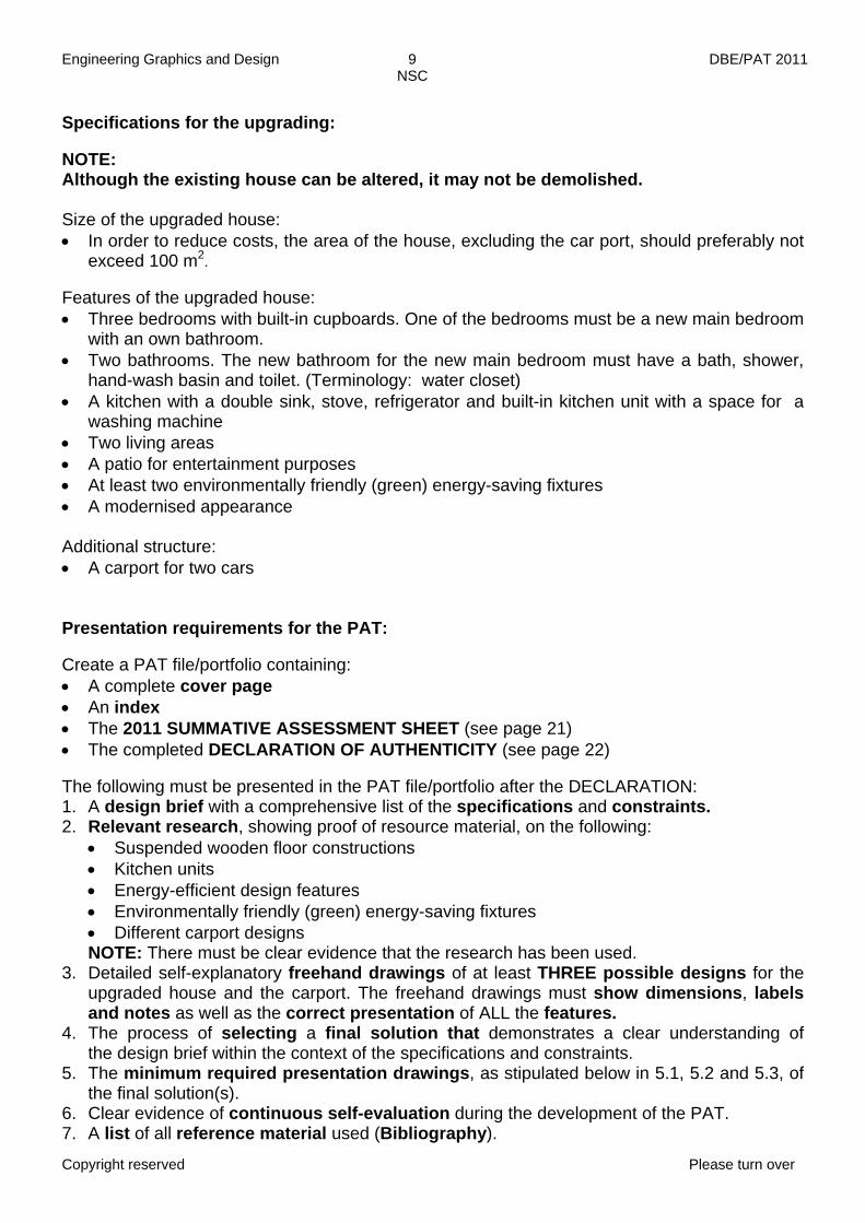
Specifications for the upgrading: NOTE: Although the existing house can be altered, it may not be demolished. Size of the upgraded house: In order to reduce costs, the area of the house, excluding the car port, should preferably not
exceed 100 m2. Features of the upgraded house: Three bedrooms with built-in cupboards. One of the bedrooms must be a new main bedroom
with an own bathroom. Two bathrooms. The new bathroom for the new main bedroom must have a bath, shower,
hand-wash basin and toilet. (Terminology: water closet) A kitchen with a double sink, stove, refrigerator and built-in kitchen unit with a space for a
washing machine Two living areas A patio for entertainment purposes At least two environmentally friendly (green) energy-saving fixtures A modernised appearance Additional structure: A carport for two cars Presentation requirements for the PAT:
Create a PAT file/portfolio containing: A complete cover page An index The 2011 SUMMATIVE ASSESSMENT SHEET (see page 21) The completed DECLARATION OF AUTHENTICITY (see page 22) The following must be presented in the PAT file/portfolio after the DECLARATION: 1. A design brief with a comprehensive list of the specifications and constraints. 2. Relevant research, showing proof of resource material, on the following:
Suspended wooden floor constructions Kitchen units Energy-efficient design features Environmentally friendly (green) energy-saving fixtures Different carport designs NOTE: There must be clear evidence that the research has been used.
3. Detailed self-explanatory freehand drawings of at least THREE possible designs for the upgraded house and the carport. The freehand drawings must show dimensions, labels and notes as well as the correct presentation of ALL the features.
4. The process of selecting a final solution that demonstrates a clear understanding of the design brief within the context of the specifications and constraints.
5. The minimum required presentation drawings, as stipulated below in 5.1, 5.2 and 5.3, of the final solution(s).
6. Clear evidence of continuous self-evaluation during the development of the PAT. 7. A list of all reference material used (Bibliography).

Engineering Graphics and Design 10 DBE/PAT 2011 NSC
Copyright reserved Please turn over
Include the following on each page of each presentation requirement: Clear numbering in accordance with the numbers of all the requirements of the PAT. The learner's name. The date of completion and submission.
5. The minimum required presentation drawings of the final solution(s): 5.1 A detailed working drawing of the proposed upgraded house and the carport, clearly
showing all the features and fixtures. The drawing must show a minimum of FOUR orthographic views drawn to a suitable scale.
The views must include: 5.1.1 A floor plan 5.1.2 A sectional elevation 5.1.3 TWO elevations, showing the front view and a side view The following must be shown on all relevant views of the working drawing: All the features and fixtures of the house and the carport All electrical fixtures Wastewater disposal systems (sewerage) Dimensions Scale(s) Labels, notes and fixture codes Cutting plane(s) All hatching detail (colouring must be in accordance with the SABS 0143 guidelines)
5.2 A complete detailed site plan drawn to a suitable scale.
The following must be shown on the site plan: The proposed upgraded house and the carport All services, sewerage and drainage connections Electrical supply to the house Driveway(s) and the complete layout of the garden Dimensions Scale Labels, notes and fixture codes NOTE: The site plan may contain artistic features or it may be rendered.
5.3 A detailed 2-point perspective drawing of the proposed upgraded house and carport,
drawn to a suitable scale. Evidence of the following must be included with the perspective drawing: All necessary construction All necessary views Relevant labels and notes NOTE: The perspective drawing may contain artistic features or it may be rendered so that it can be used as the cover page of the architect's presentation.
All the drawings must be presented on appropriately sized drawing sheets, correctly set up with borders and appropriate civil title blocks/panels. Untidy and messy work as well as the late submission of the presentation requirements will be penalised.

Engineering Graphics and Design 11 DBE/PAT 2011 NSC
Copyright reserved Please turn over
NOTE: All drawings must comply with the guidelines contained in the SANS 0143 Code of Practice for Building Drawings. Drawing methods The PAT must provide clear evidence that a high level of competency has been attained by the learner in all three of the following drawing methods: Freehand drawing: ALL preliminary design drawings and diagrams produced during the
design process (3). Instrument drawing(s): The site plan (5.2) and/or 2-point perspective drawing (5.3). CAD (Computer-aided Design/Drawing): The working drawing (5.1). Either the site plan
(5.2) or the 2-point perspective drawing (5.3) may also be drawn with CAD.
NOTE: Schools that do not have CAD facilities must complete all the required presentation drawings (5.1, 5.2 and 5.3) as instrument drawings. Assessment criteria The following assessment tools will be used to assess the PAT: 1. The rubric displayed in ANNEXURE A for assessing the design process and meeting
deadlines. This mark will contribute 25 marks to the final PAT mark. 2. The rubric displayed in ANNEXURE B for assessing the correctness of the presentation
drawings. This mark will contribute 50 marks to the final PAT mark. 3. The rubric displayed in ANNEXURE C for assessing drawing presentation, drawing
methods, quality of line work, printing and dimensioning. This mark will contribute 25 marks to the final PAT mark.
Engineering Graphics and Design 12 DBE/PAT 2011 NSC
Copyright reserved Please turn over
PRACTICAL ASSESSMENT TASK 2
A MECHANICAL DESIGN PROJECT
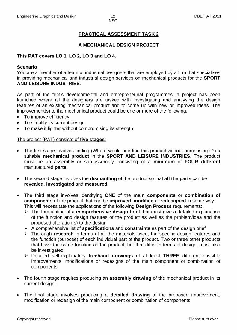
This PAT covers LO 1, LO 2, LO 3 and LO 4. Scenario You are a member of a team of industrial designers that are employed by a firm that specialises in providing mechanical and industrial design services on mechanical products for the SPORT AND LEISURE INDUSTRIES. As part of the firm's developmental and entrepreneurial programmes, a project has been launched where all the designers are tasked with investigating and analysing the design features of an existing mechanical product and to come up with new or improved ideas. The improvement(s) to the mechanical product could be one or more of the following: To improve efficiency To simplify its current design To make it lighter without compromising its strength The project (PAT) consists of five stages: The first stage involves finding (Where would one find this product without purchasing it?) a
suitable mechanical product in the SPORT AND LEISURE INDUSTRIES. The product must be an assembly or sub-assembly consisting of a minimum of FOUR different manufactured parts.
The second stage involves the dismantling of the product so that all the parts can be
revealed, investigated and measured. The third stage involves identifying ONE of the main components or combination of
components of the product that can be improved, modified or redesigned in some way. This will necessitate the applications of the following Design Process requirements: The formulation of a comprehensive design brief that must give a detailed explanation
of the function and design features of the product as well as the problem/idea and the proposed alteration(s) to the design
A comprehensive list of specifications and constraints as part of the design brief Thorough research in terms of all the materials used, the specific design features and
the function (purpose) of each individual part of the product. Two or three other products that have the same function as the product, but that differ in terms of design, must also be investigated.
Detailed self-explanatory freehand drawings of at least THREE different possible improvements, modifications or redesigns of the main component or combination of components
The fourth stage requires producing an assembly drawing of the mechanical product in its
current design. The final stage involves producing a detailed drawing of the proposed improvement,
modification or redesign of the main component or combination of components.
Engineering Graphics and Design 13 DBE/PAT 2011 NSC
Copyright reserved Please turn over
Specifications of the mechanical product: The product must be an assembly or sub-assembly consisting of a minimum of FOUR
different manufactured parts. The product must have at least two (2) moveable components with the one's movement
leading to the movement of the other. NOTE: Your teacher must approve the mechanical product you intend to use for the project
(PAT) in order to ensure that it complies with all the requirements and that it is of an appropriate higher order Grade 12 complexity.
The selected mechanical product must be submitted, in a dismountable state, as part of the PAT presentation.
Presentation requirements for the PAT:
Create a PAT file/portfolio containing:
A complete cover page An index The 2011 SUMMATIVE ASSESSMENT SHEET (see page 21) The completed DECLARATION OF AUTHENTICITY (see page 22) The following must be presented in the PAT file/portfolio after the DECLARATION: 1. A design brief with a comprehensive list of the specifications and constraints. 2. Relevant research, showing proof of resource material, on the following:
All the materials that are used for the parts of the product Specific design features of the product The function (purpose) of each individual part of the product Two or more other products that have the same function, but that differ in terms of their
design. NOTE: There must be clear evidence that the research has been used.
3. Detailed self-explanatory freehand drawings of at least THREE possible improvements, modifications or redesigns. The freehand drawings must show dimensions, labels and notes as well as the correct presentation of ALL the features.
4. The process of selecting a final solution that demonstrates a clear understanding of the design brief within the context of the specifications and constraints.
5. The minimum required presentation drawings, as stipulated below in 5.1, 5.2 and 5.3, of the product and the final solution(s).
6. Clear evidence of continuous self-evaluation during the development of the PAT. 7. A list of all reference material used (Bibliography). Include the following on each page of each presentation requirement: Clear numbering in accordance with the numbers of all the requirements of the PAT. The learner's name. The date of completion and submission.

Engineering Graphics and Design 14 DBE/PAT 2011 NSC
Copyright reserved Please turn over
5. The minimum required presentation drawings of the product and final solution(s): 5.1 An assembly drawing, of all the parts, of the current design of the product. The drawing
must show a minimum of FOUR appropriate orthographic views drawn to a suitable scale. The views must include:
5.1.1 The front view 5.1.2 A second primary (main) view 5.1.3 Any TWO other secondary views NOTE: At least ONE of the primary views must be sectioned. The following must be shown on the views of the assembly drawing: Dimensions Scale Labels and notes Cutting plane(s) All hatching detail
5.2 A detailed drawing of the selected improvement, modification or redesign of the main
component or combination of components. The drawing must show a minimum of THREE appropriate orthographic views drawn to a suitable scale.
NOTE: One of the views must be the front view. At least ONE of the views must be sectioned or contain sections. The following must be included on the views of the detailed drawing: A comprehensive list of explanatory labels and notes Relevant welding and machining symbols Dimensions Cutting plane(s) All hatching detail
5.3 A detailed isometric drawing of a combination of components of the product, drawn to a
suitable scale. NOTE: The drawing must be of an appropriate higher order Grade 12 complexity.
The following must be included on the isometric drawing: All necessary construction Relevant labels and notes
NOTE: The isometric drawing may contain artistic features or it may be rendered. All the drawings must be presented on appropriately sized drawing sheets, correctly set up with borders and appropriate mechanical title blocks. Untidy and messy work as well as the late submission of the presentation requirements will be penalised. NOTE: All drawings must comply with the guidelines contained in the SANS 0111 Code of Practice for Engineering Drawings.

Engineering Graphics and Design 15 DBE/PAT 2011 NSC
Copyright reserved Please turn over
Drawing methods The PAT must provide clear evidence that a high level of competency has been attained by the learner in all three of the following drawing methods: Freehand drawing: ALL preliminary design drawings and diagrams produced during the
design process (3). Instrument drawing(s): The detailed drawing (5.2) and/or isometric drawing (5.3). CAD (Computer-aided Design/Drawing): The assembly drawing (5.1). Either the detailed
drawing (5.2) or the isometric drawing (5.3) may also be drawn with CAD. NOTE: Schools that do not have CAD facilities must complete all the required presentation drawings (5.1, 5.2 and 5.3) as instrument drawings. Assessment criteria The following assessment tools will be used to assess the PAT: 1. The rubric displayed in ANNEXURE A for assessing the design process and meeting
deadlines. This mark will contribute 25 marks to the final PAT mark. 2. The rubric displayed in ANNEXURE B for assessing the correctness of the presentation
drawings. This mark will contribute 50 marks to the final PAT mark. 3. The rubric displayed in ANNEXURE C for assessing drawing presentation, drawing
methods, quality of line work, printing and dimensioning. This mark will contribute 25 marks to the final PAT mark.

Engineering Graphics and Design 16 DBE/PAT 2011 NSC
Copyright reserved Please turn over
A SIMPLIFIED RUBRIC FOR THE ALLOCATION OF MARKS
MARK ALLOCATION for all aspects/criteria of the PAT
DESCRIPTION for MARK GENERAL
INDICATORS ± % MARK
ALL/MORE than ALL the REQUIREMENTS are met - 'PERFECT' - Error free 100% 10
ALL (ALMOST ALL) the REQUIREMENTS are met - OUTSTANDING -
Very few errors
90% + 9
ALMOST ALL (MOST) the REQUIREMENTS are met- VERY GOOD - Few errors 80% + 8
The REQUIREMENTS are SUBSTANTIALLY met - GOOD -
Some errors
70% + 7
The REQUIREMENTS are ADEQUATELY met - SATISFACTORY -
60% + 6
The REQUIREMENTS are MODERATELY met - ACCEPTABLE -
Many errors
50% + 5
ONLY SOME of the REQUIREMENTS are met - UNACCEPTABLE -
40% + 4
VERY FEW of the REQUIREMENTS are met - NOT ACHIEVED - Mostly wrong
30% + Only a few
correct features 3
The REQUIREMENTS are NOT met
- VERY BAD - Completely
wrong
29% & LESS
'Something' done very
wrongly/badly
2
1
NOT DONE! No work
handed in! Nothing to
mark! 0

Engineering Graphics and Design 17 DBE/PAT 2011 NSC
Copyright reserved Please turn over
ANNEXURE A
A RUBRIC FOR ASSESSING THE DESIGN PROCESS
LEVELS OF PERFORMANCE
RATING SCALE 7 6 5 4 3 2 1 100% - 80% 79% - 70% 69% - 60% 59% - 50% 49% - 40% 39% - 30% 29% - 0%
MARK ALLOCATION
10 9 8 7 6 5 4 3 2 1 0 100% 99% - 90% 89% - 80% 79% - 70% 69% - 60% 59% - 50% 49% - 40% 39% - 30% 29% - 20% 19% - 1% 0%
1. A design brief demonstrating a clear understanding of the
scenario with a list of the specifications and
constraints.
The design brief with a comprehensive list of the specifications and the constraints
demonstrating an in-depth and comprehensive understanding of the
scenario
The design brief with a complete or incomplete list of the specifications and
the constraints demonstrating a satisfactory understanding of the scenario
The design brief with the possibility of an incomplete list of the specifications and/or the constraints demonstrating an elementary understanding of the
scenario
A design brief with either a very vague or no list of
specifications and or constraints demonstrating little or no
understanding of the scenario
2. Evidence of relevant 'external' research.
Shows evidence of in-depth and thorough relevant 'external' research that is used
within the final solution
Shows evidence of satisfactory relevant 'external' research of which some is used
within the final solution
Shows evidence of limited research of which little to none is used within the
final solution
Shows very little evidence of any research or research that is
inappropriate
3. A record of at least THREE possible
detailed freehand drawing solutions
A wide range of possible solutions, which are clearly, logically and comprehensively
presented with dimensions and notes with ALL the features presented correctly
A satisfactory number of possible solutions, which are clearly recorded and
presented with dimensions and notes with most features presented correctly
A limited number of possible solutions, which are recorded and presented with no dimensions and
notes with only some features presented correctly
Shows little to no possible solutions
4. Selecting a final solution that
demonstrates a clear understanding of the
design brief. (correctness/functionality
/practicality of design)
A thorough selection process and a final solution that demonstrates a clear in-depth and comprehensive understanding of the
design brief
A substantial selection process and a final solution that demonstrates a
satisfactory understanding of the design brief
An incomplete or no selection process and a final solution that
demonstrates a limited understanding of the design brief
No selection process and a final solution that demonstrates little to
no understanding of the design brief
6. Clear evidence of continuous self-
evaluation and the meeting of deadlines of all the requirements of
the PAT
Clear evidence of continuous comprehensive self-evaluation of all the requirements of the PAT and all the requirements were handed in
on the due dates.
Evidence of satisfactory self-evaluation of most of the requirements of the PAT and
most of the requirements were handed in by the extension date
Evidence of limited self-evaluation of some of the requirements of the PAT
and few deadlines were met. Extension dates were missed but most stages
were handed in
Little or no evidence of any self- evaluation is shown and none of the
deadlines were met
7. The presentation of the complete PAT portfolio with the
inclusion of a bibliography
All the required presentations of the PAT are complete and neatly presented in a logical and orderly sequence in the PAT
file/portfolio that also contains a comprehensive bibliography
Most of the required presentations of the PAT are complete and neatly presented in
a orderly sequence in the PAT file/portfolio that also contains a
satisfactory bibliography
Some of the required presentations of the PAT are complete and presented in the PAT file/portfolio that contains a
limited bibliography
Very few of the required presentations are complete and
poorly presented in the PAT file/portfolio that contains a little to
no bibliography

Engineering Graphics and Design 18 DBE/PAT 2011 NSC
Copyright reserved Please turn over
ANNEXURE B
RUBRIC FOR ASSESSING CORRECTNESS OF THE PRESENTATION DRAWING
LEVELS OF PERFORMANCE
RATING SCALE 7 6 5 4 3 2 1 100% - 80% 79% - 70% 69% - 60% 59% - 50% 49% - 40% 39% - 30% 29% - 0%
MARK ALLOCATION 10 9 8 7 6 5 4 3 2 1 0
100% 99% - 90% 89% - 80% 79% - 70% 69% - 60% 59% - 50% 49% - 40% 39% - 30% 29% - 20% 19% - 1% 0%
All drawing sheets are appropriately set up with a border and a appropriate
title block/pane.l
All drawing sheets are appropriately set up with more than the minimum
requirements.
Most of the drawing sheets are appropriately set up with the minimum
requirements.
Only some of the drawing sheets are set up with less than minimum
requirements. Little or no page set-up is evident.
Ort
ho
gra
ph
ic d
raw
ing
s
5.1
PAT 1: Assess each view's 'design' and correctness of the presentation according to the specifications and constraint, the stipulated requirements and 'EGD' drawing principals. PAT 2: Assess each view's accurate reflection of the product and the correctness of the presentation according to the stipulated requirements and 'EGD' drawing principals.
5.
1.1
View 1 PAT 1: Plan PAT 2: Front view
The view meets more than the minimum requirements and is error
free.
The view meets the minimum requirements but contains some
errors.
The view contains less than the minimum requirements and
contains many errors.
Little or no evidence of the required view
5.1.
2 View 2
PAT 1: Section PAT 2: 2nd main view
The view meets more than the minimum requirements and is error
free.
The view meets the minimum requirements but contains some
errors.
The view contains less than the minimum requirements and
contains many errors.
Little or no evidence of the required view
5.1.
3 View 3
PAT 1: 2 elevation PAT 2: 2 secondary views
The views meet more than the minimum requirements and are error
free.
The views meet the minimum requirements but contain some
errors.
The views contain less than the minimum requirements and
contain many errors.
Little or no evidence of the required view
5.2
PAT 1 and PAT 2: Assess each view's 'design' and correctness of the presentation according to the specifications and constraint, the stipulated requirements and 'EGD' drawing principals.
PAT 1: Site plan
PAT 2: Detailed drawing
The site plan/detailed drawing meets more than minimum requirements and
is error free.
The site plan/detailed drawing meets the minimum requirements but
contains some errors.
The site plan/detailed drawing contains less than the minimum requirements and contains many
errors.
Little or no evidence of required views
Pic
tori
al
dra
win
g
5.3
The correct drawing method and presentation
PAT 1: 2-point perspective PAT 2: Isometric
Thorough knowledge of the correct pictorial drawing method and the
answer meets more than the requirements and reflects the correct
size and proportion of all the features and is error free and the presentation
is outstanding.
Satisfactory knowledge of the correct pictorial drawing method and the
answer meets the requirements and reflects the correct size and
proportion of most of the features but contains some errors and the presentation is satisfactory.
Some knowledge of the pictorial drawing method is shown, but the
answer reflects poor or incorrect size and proportion and many of the features contain many errors
and the presentation is poor.
Little or no evidence of required drawings

Engineering Graphics and Design 19 DBE/PAT 2011 NSC
Copyright reserved Please turn over
ANNEXURE C RUBRIC FOR ASSESSING DRAWING METHOD, SKILLS AND PRESENTATION
LEVELS OF PERFORMANCE
CRITERIA 7 6 5 4 3 2 1 100% - 80% 79% - 70% 69% - 60% 59% - 50% 49% - 40% 39% - 30% 29% - 0%
MARK ALLOCATION 10 9 8 7 6 5 4 3 2 1 0 100% 99% - 90% 89% - 80% 79% - 70% 69% - 60% 59% - 50% 49% - 40% 39% - 30% 29% - 20% 19% - 1% 0%
Fre
ehan
d d
raw
ing
TE
CH
NIQ
UE
The drawings display good proportion and
size.
The features show outstanding proportion and size.
The features show satisfactory proportion and size.
The features show poor proportion and size.
The features show very little or no proportion.
Final drawing presentation is neat and there is consistency of line work/line quality and
printing
Drawings are very neat and all line work/line quality, printing and dimensioning are
outstanding and consistent
Drawings are neat and line work/line quality, printing and dimensioning is generally good
and mostly consistent
Drawings are untidy with inconsistent line work/line quality,
printing and dimensioning
The line work/line quality, printing and dimensioning are
unacceptable
Inst
rum
ent
dra
win
g
TE
CH
NIQ
UE
The drawings display the correct use of
drawing instruments, drawing methods and
techniques
The drawings display the correct use of drawing instruments and an outstanding
application of drawing methods and techniques
The drawings display the correct use of drawing instruments and a satisfactory and
mostly correct application of drawing methods and techniques
The drawings display the correct use of drawing instruments and a
poor and often incorrect application of drawing methods
and techniques
The drawings display an incorrect use of drawing
instruments with incorrect applications of drawing
methods and techniques
Final drawing presentation is neat and there is consistency of line work/line quality and
printing
Drawings are very neat and all line work/line quality, printing and dimensioning are
outstanding and consistent
Drawings are very neat and the line work/line quality, printing and dimensioning are
generally good and mostly consistent
Drawings are untidy and the line work/line quality, printing and
dimensioning are inconsistent
The line work/line quality, printing and dimensioning are
unacceptable
CA
D d
raw
ing
(ANNEXURE D) A 'RUBRIC FOR ASSESSING CAD DRAWING SKILLS, KNOWLEDGE AND ABILITY'
T
EC
HN
IQU
E
The level of competence
displayed in using a CAD system
Displays a high level of skills, knowledge and ability in using a CAD system
Displays a satisfactory level of skills, knowledge and ability in using a CAD system
Displays a poor level of skills, knowledge and ability in using a
CAD system
Shows little to no skills, knowledge or ability in using a
CAD system
The layout and correctness of the final drawing
presentation 100%-80% 79%-70% 69%- 60% 59%– 50% 49%- 40% 39%- 30% 29%-0%

Engineering Graphics and Design 20 DBE/PAT 2011 NSC
Copyright reserved Please turn over
ANNEXURE D
A RUBRIC FOR ASSESSING CAD DRAWING SKILLS, KNOWLEDGE AND ABILITY
LEVELS OF PERFORMANCE
CRITERIA 7 6 5 4 3 2 1
100% - 80% 79% - 70% 69% - 60% 59% - 50% 49% - 40% 39% - 30% 29% - 0%
MARK ALLOCATION
10 9 8 7 6 5 4 3 2 1 0 100% 99% - 90% 89% - 80% 79% - 70% 69% - 60% 59% - 50% 49% - 40% 39% - 30% 29% - 20% 19% - 1% 0%
Set up a drawing interface Is able to set up a drawing interface without
any assistance displaying a high level of skills, knowledge and ability
Is able to set up a drawing interface with a little assistance displaying a satisfactory level
of skills, knowledge and ability
Is able to set up a drawing interface with some assistance displaying a lack of
skills, knowledge and ability
Shows little to no understanding of setting up a drawing interface
Set up a 2D/3D drawing environment
Is able to set up a 2D and 3D drawing environment without any assistance
displaying a high level of skills, knowledge and ability
Is able to set up a 2D and 3D drawing environment with a little assistance displaying
a satisfactory level of skills, knowledge and ability
Is able to set up a 2D and 3D drawing environment with some assistance
displaying a lack of skills, knowledge and ability
Shows little to no understanding of setting up a 2D/3D drawing
environment
Set up layers with properties assigned to
each layer
Is able to set up layers and assign properties to each layer without any assistance
displaying a high level of skills, knowledge and ability
Is able to set up layers and assign properties to each layer with a little assistance displaying
a satisfactory level of skills, knowledge and ability
Is able to set up layers and assign properties to each layer with some
assistance displaying a lack of skills, knowledge and ability
Shows little to no ability to set up layers and assign properties to
each layer
Set up a drawing sheet with a border and a title
block
Is able to set up a drawing sheet with a border and a title block without any assistance
displaying a high level of skills, knowledge and ability
Is able to set up a drawing sheet with a border and a title block with some assistance displaying a satisfactory level of skills,
knowledge and ability
Is able to set up a drawing sheet with a border and a title block with some
assistance displaying a lack of skills, knowledge and ability
Shows little to no ability to set up a drawing sheet with a border and a
title block
Show evidence of the correct use of the drawing
tools
Thorough and detailed evidence is shown of using the drawing tools correctly
Satisfactory evidence is shown of using the drawing tools correctly
Limited evidence is shown of using the drawing tools correctly
Little to no evidence is shown of using the drawing tools correctly
Show ability to save and retrieve work
Is able to save and retrieve work without any assistance displaying a high level of skills,
knowledge and ability
Is able to save and retrieve work with a little assistance displaying a satisfactory level of
skills, knowledge and ability
Is able to save and retrieve work with some assistance displaying a lack of
skills, knowledge and ability
Shows little to no ability to save/retrieve work
Show ability to plot a drawing
Is able to plot a drawing without any assistance displaying a high level of skills,
knowledge and ability
Is able to plot a drawing with a little assistance displaying a satisfactory level of skills,
knowledge and ability
Is able to plot a drawing with some assistance displaying a lack of skills,
knowledge and ability
Shows little to no ability to plot work
The layout and correctness of the final drawing presentation
100%-80% 79%-70% 69%- 60% 59%– 50% 49%- 40% 39%- 30% 29%-0%

Engineering Graphics and Design 21 DBE/PAT 2011 NSC
Copyright reserved Please turn over
PRACTICAL ASSESSMENT TASK 2011 SUMMATIVE ASSESSMENT SHEET
SCHOOL: …………………………………………………………………………..………. NAME OF LEARNER: …………………………………………………………............... (SURNAME AND INITIALS) EXAMINATION NUMBER: ……………………………………………………………….
PART A: Design Process PART B: Presentation Drawings Drawing competency and skillCRITERIA MARK CRITERIA MARK CRITERIA MARK
AN
NE
XU
RE
A
1
A design brief with a comprehensive list of the specifications and constraints
demonstrating a clear understanding of the
scenario
All drawing sheets are appropriately set up with a border and a
appropriate title block/panel
Fre
ehan
d d
raw
ing
s A
NN
EX
UR
E C
M
ET
HO
D
The drawings display good proportion and
size
Ort
ho
gra
ph
ic d
raw
ing
A
NN
EX
UR
E B
Ass
ess
the
follo
win
g:
P
AT
1:
Th
e d
esig
n
and
co
rrec
tnes
s
P
AT
2:
Th
e ac
cura
cy a
nd
co
rrec
tnes
s 5.1.
1 View 1
PAT 1: Plan PAT 2: Front view
Final drawing presentation is neat and there is
consistency of line work/ line quality, printing and
dimensioning
2 Evidence of relevant
'external' research 5.
1.2
View 2
PAT 1: Section PAT 2: 2nd main
view
Inst
rum
ent
dra
win
gs
AN
NE
XU
RE
C
ME
TH
OD
The drawings display the correct use of
drawing instruments, drawing methods and
techniques
3
A record of at least THREE possible
detailed freehand drawing solutions
5.1.
3
View 3
PAT 1: 2 elevations PAT 2: 2 secondary views
4
Selecting a final solution that
demonstrates a clear understanding of the design brief
Ass
ess
the
des
ign
an
d
corr
ectn
ess
5.2
PAT 1: Site plan
PAT 2: Detailed drawing
Final drawing presentation is neat and there is
consistency of line work/ line quality, printing and
dimensioning
6
Clear evidence of continuous self-
evaluation and the meeting of deadlines
of all the requirements of the
PAT
Pic
tori
al d
raw
ing
A
NN
EX
UR
E B
5.3
The correct drawing method and the presentation of the drawing PAT 1: 2-p perspective PAT 2: Isometric
CA
D d
raw
ing
s A
NN
EX
UR
E D
M
ET
HO
D
The level of competence displayed
in using a CAD system
The layout and correctness of the final drawing presentation
7
The presentation of the complete PAT portfolio with the
inclusion of a bibliography
TOTAL without 'CAD'
TOTAL with 'CAD'
Criteria Total Criteria Total CALCULATION without
'CAD'
CALCULATION CALCULATION CALCULATION with 'CAD'
Teacher's TOTAL Teacher's TOTAL Teacher's TOTAL
TOTAL: A / 25 TOTAL: B / 50 TOTAL: C / 25
Moderated TOTAL Moderated TOTAL Moderated TOTAL
TOTAL: A / 25 TOTAL: B / 50 TOTAL: C / 25
TEACHER'S TOTAL: A + B + C = / 100ASSESSOR:
Initial MODERATOR:
Initial
MODERATED TOTAL: A + B + C = / 100

Engineering Graphics and Design 22 DBE/PAT 2011 NSC
Copyright reserved
DECLARATION OF AUTHENTICITY
To be submitted with each learner's Practical Assessment Task portfolio NAME OF THE SCHOOL: ……………………………………………………………………................ NAME OF LEARNER: ………………………………………………………........................................
(SURNAME AND INITIALS)
EXAMINATION NUMBER: ………………………………………….…………………… I hereby declare that all the contents of the Practical Assessment Task submitted by myself for assessment is my own original work and has not been plagiarised, copied from someone else or previously submitted for assessment. _________________________ ___ / ___ / 2011 SIGNATURE OF CANDIDATE DATE (DD / MM / YY) NAME OF TEACHER: ……………………………………………………………………….……………
(SURNAME AND INITIALS) As far as I know, the above declaration by the candidate is true and I accept that the PAT offered is his/her own work. _______________________ ___ / ___ / 2011 SIGNATURE OF TEACHER DATE (DD / MM / YY)
SCHOOL STAMP