Guidelines for Avoiding Galvanic Corrosion in Nuclear ...
29
Guidelines for Avoiding Galvanic Corrosion in Nuclear Plant Piping Systems George Licina & Heather Jackson Structural Integrity Associates, Inc. San Jose, CA 17 th International Environmental Degradation Conference Ottawa, ON August 2015
Transcript of Guidelines for Avoiding Galvanic Corrosion in Nuclear ...

Guidelines forAvoiding Galvanic
Corrosion in NuclearPlant Piping Systems
George Licina & Heather Jackson
Structural Integrity Associates, Inc.
San Jose, CA
17th International Environmental Degradation ConferenceOttawa, ONAugust 2015

The Problem
• Nuclear power plants continue to replace above ground carbon steelpipe (bare or lined) with more corrosion resistant alloys (CRAs)
More erosion and erosion-corrosion resistant stainless steelalloys
6% molybdenum or high molybdenum duplex stainless steels forcorrosion resistance
• “Alloying up” creates a galvanic couple
• Most common approach is to use insulating kits
In piping systems that are electrically isolated, that works well,but
In nuclear plants, where all buried piping, structures, etc. arecommonly grounded, the common grounding can “defeat” theinsulating kit, merely changing the shortest electron path fromthe shortest distance between the carbon steel and the corrosionresistant alloy to a path through the plant grounding grid

Fundamentals/3
Fundamentals of Corrosion
Corrosion is Oxidation of Metal to a More
Stable State
Oxidation Requires Transfer of Electrons
Require:• Electrodes (anode = oxidation; cathode = reduction)• Electrolyte (conduction of ions)• Electron Path
ALL THREE ARE NECESSARY FOR CORROSIONTO PROCEED

Fundamentals/4
Corrosion Phenomena
Electrochemical Aspects of Corrosion
Oxidation at the Anode
Reduction at the Cathode
Potential
Current

Fundamentals/5
GENERAL CORROSION
Fundamentals/6
GENERAL CORROSION

Fundamentals/7
GALVANIC SERIES –FLOWING SEA WATER (8 TO 13 ft./sec. 50°-80°F)
Volts: Saturated Calomel Half-Cell Reference Electrode

Fundamentals/8
GALVANIC SERIES –
HUNTINGTON CITY WATER, 25C
Volts: Saturated Calomel Half-Cell Reference Electrode
92347r1
+0.4
+0.3
+0.2
+0.1 0
-0.1
-0.2
-0.3
-0.4
-0.5
-0.6
-0.7
-0.8
-0.9
-1.0
-1.1
-1.2
-1.3
-1.4
-1.5
-1.6
-1.7
-1.8
MagnesiumManganese
Cast IronZinc
AluminumAluminum Alloy 5052
Mild SteelTinLead
Nickel - SilverCopperAlloy 20Cb3Alloy 18-18-2
Brass AlloysAlloy 3RE6070 - 30 Copper-Nickel90 - 10 Copper-NickelAlloy EFE62
Bronze AlloysAlloy 6XAlloy 17-4PHAlloy 255 (Ferrallium)Alloy 230 (Coronel)
Alloy 26-1, 26-1 - 1/4Alloys C276, G, X
Alloy 254 SLXMONEL alloys 400, R405, K500Alloy B, P, PD (Illium)INCOLOY alloy 800, 825, 840
Nickel 200, 270Stainless Steel 304, 316, 317, 403
INCONEL alloys 600, 617, 618, 625, 671, 690, 702, X750TitaniumAlloy 700 (Jessop)
+0.64 - 0.76V Platinum
[Crum and Scarberry, Corrosion of Nickel Base Alloys Conference Proceedings - ASM 1985]
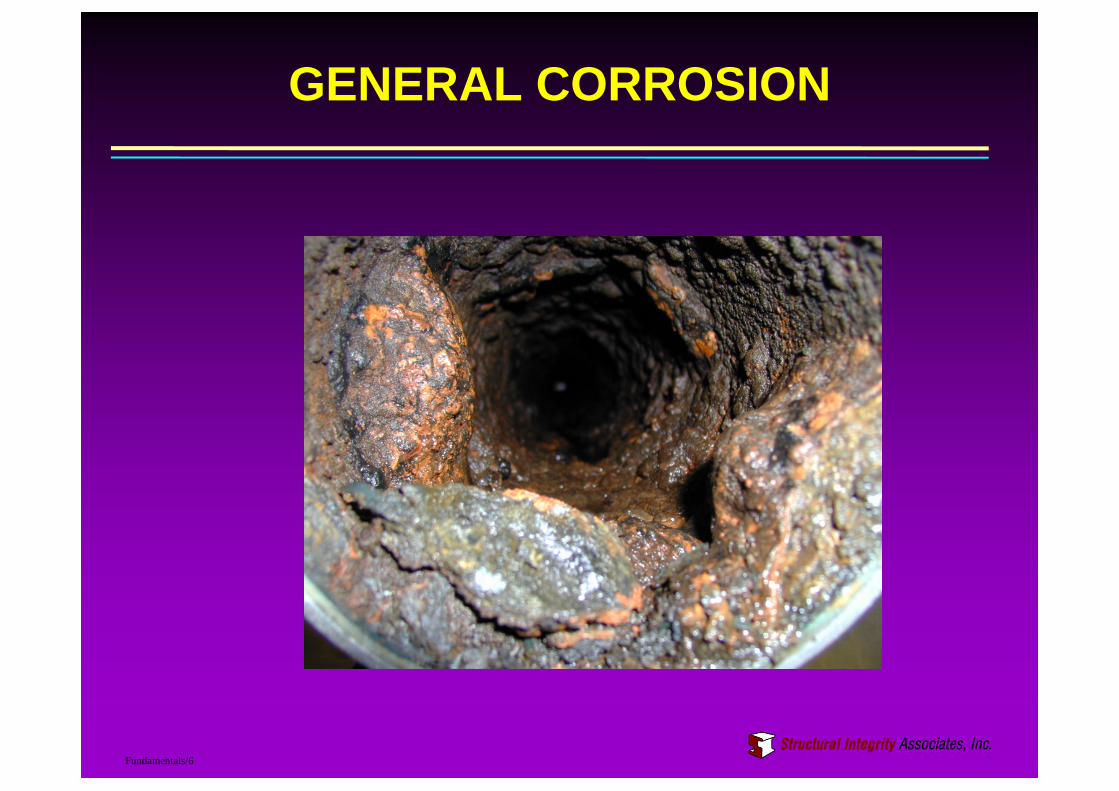
GALVANIC CORROSION
CARBON STEEL/STAINLESS STEEL

GALVANIC CORROSION
TITANIUM TUBES/ALUMINUM BRONZE TUBESHEET
Images Courtesy 2012 – Condenser Life
Cycle Seminar ©

Fundamentals/11
GALVANIC CORROSION
AL-6X TUBE/MUNTZ TUBESHEET

Fundamentals/12
GALVANIC CORROSION
EFFECT OF CONDUCTIVITY
G alvanicS eries-C oncentrate dHydroc hloricAc idat25° C[Crum andScarberry ,Corrosiono fNickelBase AlloysConf erenceProcee dings-ASM 1985]
+0.4
+0.3
+0.2
+0.10
-0.1
-0.2
-0.3
-0.4
-0.5
-0.6
-0.7
-0.8
-0.9
-1.0
-1.1
-1.2
-1.3
-1.4
-1.5
-1.6
-1.7
-1.8
MagnesiumManganeseAluminumZincCadmiumLead
Alloy255(Ferralium)HighPurityIronCopperAlloyPE62Alloy26-1,26-11/4CarbonSteelMONELalloy451TinAlloy18-18-2Alloy3RE60
Alloy17-4pHINCOLOYalloy840,50Ni-50CrBrassAlloysNickelSilver90-10Copper-NickelBronzeAlloys70-30Copper-NickelAlloy230(Corronel)Alloy70Cb3StainlessSteel304,316,316L,317
Alloy20CastIronNi-Resist2Alloy254SLXAlloy904LINCONELalloys600,601,690,702,748,X750INCOLOYalloy825AlloyB,P,PD(Illium)AlloyG
Alloy6X(HA)MONELalloys400,404,405R,K500Nickel200,270Alloy700(Jessop)Alloy6XSilverAlloyGINCOLOYalloy800INCONELalloys617,618E,625AluminumAlloy5052
StainlessSteel430Titanium+0.4-0.48VPlatinum
92345r1
92364r1
Active MemberNoble Member
Active MemberNoble Member
Galvanic Corrosion in High Conductivity Environment
Galvanic Corrosion in Low Conductivity Environment

Schematic of Plant Piping

Insulating Kits

Insulating Kits

Industry Practices
• Use insulating kits. Controlled procedure.Check pre-tensioning and post-tensioningresistance
• Use insulating kits. Controlled procedure.
• Use insulating kits BUT concerns withgasket damage. Customized kits andspecialized installation procedures.

Specialized Kit

Testing Procedures
Under dry system conditions
• Continuity test with a multimeter (50 MΩ or greater, DC method)
• Megger test at 500 volts with a better than 1MΩ resistance. ( DC)
• Radio frequency isolation verification (go/no go) (ACmethod):
Introduce radio frequency on one side of the joint.
Look for that same frequency and very nearly the samemagnitude on the other side.
If media is in the piping system (after installation or in service)
• Potential difference between the two flanges (potential ofeach flange vs. copper/copper sulfate reference electrode)
or
• use an RF isolation tester.
• done on the outside of the pipe.

Monolithic Isolation Joint

Carbon Steel in Seawater
-800
-600
-400
-200
0
200
400
1.E-04 1.E-03 1.E-02 1.E-01 1.E+00 1.E+01 1.E+02 1.E+03 1.E+04 1.E+05 1.E+06
Icorr, A/m2
Po
ten
tia
l,m
Vv
s.
SC
E
CS Anodic
CS Cathodic
45 mpy

Stainless Steel in Seawater
-800
-600
-400
-200
0
200
400
1.E-04 1.E-03 1.E-02 1.E-01 1.E+00 1.E+01 1.E+02 1.E+03 1.E+04 1.E+05 1.E+06
Icorr, A/m2
Po
ten
tia
l,m
Vv
s.
SC
E
SS Anodic
SS Cathodic
0.3 mpy
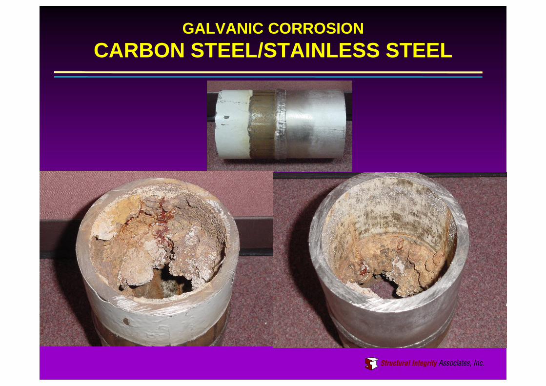
CS/SS Couple - Seawater
-800
-600
-400
-200
0
200
400
1.E-04 1.E-03 1.E-02 1.E-01 1.E+00 1.E+01 1.E+02 1.E+03 1.E+04 1.E+05 1.E+06
Icorr, A/m2
Po
ten
tia
l,m
Vv
s.
SC
E
CS Anodic
CS Cathodic
SS Anodic
SS Cathodic
287 mpy0.3 mpy 45 mpy

“Resistance” Required to Eliminate GalvanicEffect
-800
-600
-400
-200
0
200
400
1.E-04 1.E-03 1.E-02 1.E-01 1.E+00 1.E+01 1.E+02 1.E+03 1.E+04 1.E+05 1.E+06
Icorr, A/m2
Po
ten
tia
l,m
Vv
s.
SC
E
CS Anodic
CS Cathodic
SS Anodic
SS Cathodic
287 mpy0.3 mpy 45 mpy

Alternative Approach – Electrolyte Path
• Insert short, electrically isolated pipingsections between the dissimilar metalswas proposed for evaluation
• Increase the electrical resistance of thewater path through which the galvaniccurrent must flow

Alternate Electrolyte Path

Potentials in Seawater - NavyLow Flow
-200
-150
-100
-50
0
50
100
150
200
250
300
0 5 10 15 20 25 30
Distance, ft
Po
ten
tial,
mV
vs.A
g/A
gC
l
No Separator Aeroquip RISIC I625 - 1 ft I625 - 3 ft I625 - 10 ft
CuNi - 1 ft CuNi - 3 ft CuNi - 10 ft

Seawater Results - Navy
Low Flow 6 fps
@ 6 mos @ 6 mos
Integrated Currents, mA-dReduction of Integrated
Currents Integrated Currents, mA-dReduction of Integrated
Currents
Separator Material Separator Material Separator Material Separator Material
70-30Cu-Ni I625 70-30Cu-Ni I625 70-30Cu-Ni I625 70-30Cu-Ni I625
SeparatorLength
0 524 524 430 430
1 403 380 23% 27% 430 472 0% -10%
3 314 246 40% 53% 261 207 39% 52%
10 287 184 45% 65% 189 132 56% 69%
@ 1 year @ 1 year
SeparatorLength
0 873 873 950 950
1 710 786 19% 10% 873 1032 8% -9%
3 644 541 26% 38% 650 547 32% 42%
10 537 455 38% 48% 435 349 54% 63%
Conclusion
• Addition of CRAs will produce a galvanic couple
• Most plants install insulating flanges at galvaniccouples
• Insulation kits present their own challenges
• Installation procedures, tests during installationprocess, etc. vary
• Commonly grounded piping can defeat insulatingflanges
• Essentially no plants test “degree of insulation”after installation
• Alternate approach, using well coated insert toincrease the electrolyte path, provides a viablealternative

Recommendations
1. Coated or non-conductive insert. The noble member in the galvanic couple (e.g., stainless steel, 6%
Mo stainless steel) should be coated: the more active member(carbon steel, coated carbon steel, etc.) should not serve as thecoated insert.
No insulating flange is required.
2. A spool that is electrically isolated with a properlyinstalled insulating kit on both ends and that has nohangers or other supports to the building.
3. Monolithic Isolation Joint. The required connections to the system will be similar metal welds
and no on-site assembly and installation of insulating flanges willbe required.
MIJs will have the exact same susceptibility to being defeating bythe common grounding that insulating flanges do.
4. Insulating kits (and all that comes along with them)