
Guidelines Digitisation of photographic materials
40
Digitisation of photographic materials Guidelines
Transcript of Guidelines Digitisation of photographic materials

Digitisation of photographic materials
Guidelines

Preface 3
1 Introduction 4
2 Digitisation of photographic materials 52.1 Workflow 52.2 Original objects 52.3 Software and settings 62.4 Digitisation 72.5 Logistics 112.6 Testing 13
3 Photographic prints, various sizes, black and white, and colour 153.1 Results 153.2 Specifications for the digitisation of photographic prints 153.3 Post-processing digital images of photographic prints 233.4 Inspection by the Contractor 233.5 Inspection by the Contracting Authority 24
4 Film-based negatives and glass plate negatives, various sizes, black and white 274.1 Results 274.2 Specifications for the digitisation of transparent objects 274.3 Post-processing digital images of transparent objects 344.4 Inspection by the Contractor 344.5 Inspection by the Contracting Authority 35
5 Current situation and future developments 38
Colophon 39
Guidelines Digitisation of photographic materials September 2010
Contents

The comprehensive document you are looking at was realized as part of the project Images forthe Future (Beelden voor de Toekomst). The document is a manual for digitisation of photographicmaterials and it is aimed at (technical) professionals.
The manual offered in this document not only serves to realize putting the large-scaledigitisation of photographs and negatives of the consortium Beelden voor de Toekomst (Images for the Future) out to tender at European level, but also to regulate the process.
Images for the Future is one of the world’s largest digitisation programmes in the field of cultural heritage, and within this the Nationaal Archief of the Netherlands is leading in thepreservation, digitisation, enrichment and online presentation of photographic materials.
With this digital publication the Nationaal Archief of the Netherlands wishes to establish andshare the knowledge it has developed in this field with colleagues. We hope it will be useful to you. We assume that this document provides the basis for various initiatives regarding thepreservation of cultural heritage.
Martin Berendse, National Archivist
nationaalarchief Guidelines Digitisation of photographic materials September 2010
3
Preface
nationaalarchief Guidelines Digitisation of photographic materials September 2010
4
The Dutch program Images for the Future (Beelden voor de Toekomst) started in 2007. A special budget of € 154 million was made available by the government over a period of 7 years to safeguard the Netherlands’ endangered photographic and audiovisual heritage. In total, 137,200 hours of video, 22,510 hours of film, 123,900 hours of audio and 2.9 millionphotographs in the collections of the Netherlands institute for Sound and Vision, EYE FilmInstitute Netherlands (formerly known as Foundation Netherlands Filmmuseum) en theNationaal Archief (the Nationaal Archief of the Netherlands) are to be restored, conserved,digitised and made accessible to the public.
As part of the European tender procedure for the digitisation of photographic materials, theconsortium partners compiled a desciptive document. The Nationaal Archief has many years ofexperience in high-quality microfilming and in the digital transfer of archive materials, which hasproven invaluable in formulating these guidelines and for creating the technical specificationsused in the tender document.
The guidelines drawn up by the Nationaal Archief correspond mainly with those compiled forpreservation scanning in the Dutch national program Metamorfoze, which focuses on thepreservation of paper heritage. The most important difference is the fact that the NationaalArchief guidelines are specifically suited to the digitisation of photographs and negatives.For example, the process of converting a negative into a positive image is defined in considerabledetail. In addition, the reference charts with known characteristics (so called ‘test targets’) aresuitable for different photographic formats. Resolutions are set in accordance with the originalimage’s format. For practical reasons, the OECF parameters have been relaxed and test targetsare not provided for each individual digital image. Last but not least, the Nationaal Archief hasadopted a meaningful file naming system. The consortium partners created special software toenable the checking of test scans by both the digitisation contractor and the principal.
The guidelines presented in this publication are an abridged version of the full technicalspecifications included in the tender document. They summarise the most essential componentsof the digitisation process for photographic materials. To help assess the tenders submitted, a more extensive set of criteria has been compiled. Also a number of questions have beenformulated in order to evaluate the tenderer’s know-how and quality. For the sake of clarity those chapters have been omitted from this document.
Chapters 2 through 4 describe the process for the digitisation of photographs and negatives. The guidelines in chapter 2 cover both formats in general, whilst chapters 3 specificallyaddresses photographs and chapter 4 negatives. The final chapter provides a brief insight intothe present situation. The digitisation project has been running for half a year and with thisexperience in mind, and also in view of recent technical developments, the Nationaal Archiefproposes to make some changes to the guidelines.
1 Introduction
nationaalarchief Guidelines Digitisation of photographic materials September 2010
5
2.1 Workflow
The expected workflow is as follows. One lot includes several collections. The ContractingAuthority offers one or – in the case of small collections – several collections on each occasion.In the case of a large collection, the Contracting Authority splits it into two or three parts. In thisway various full or part projects for each lot are created .
For each of these, agreements are reached regarding the planning and duration of its digitisation.The Contracting Authority supplies exact specifications for that process, which fall within thegeneral frameworks defined in the Descriptive Document. The Contractor draws up a final reporton each full or part project. A work order form is used for this purpose.
The collection remains with the Contractor until the corresponding full or part project is approvedby the Contracting Authority. This is so that the Contractor is still able to correct any mistakes.Once the digital files have been approved, the source material is returned and then checked forcompleteness and possible damage.
Arrangements may be made concerning the partial delivery of larger part projects.
2.2 Original objects
Handling photographic materialsThe workplace must be kept clean and tidy. It is not permitted to eat, drink or smoke in theworkplace and, as far as possible, it must be kept free of dust. The workplace must offersufficient space for source materials and packaging. Damage caused by wearing jewellery orloose clothing must be prevented. It is only permitted to handle the source material with suitableclean gloves. Sharp objects are prohibited in the workplace and it is only permitted to write inpencil in the vicinity of the source materials.
If it is necessary to remove dust from source material, a safe method must be used. This mustleave no traces (eg. oil) on the original object (as occurs when using compressed air withoutair-oil separators). The source material must not be scratched (as caused by using brushes). The contractor must not use any solvents or wet methods to remove dirt or dust. The use ofaerosols with air is prohibited, unless it can be proven that these are suitable for the job.
Preparing for digitisation The Contracting Authority ensures that the source materials can be handled easily. Lists withseries of inventory and/or box numbers are provided for each full or part project. If anything isunclear, it is essential that the Contracting Authority be contacted immediately.
If possible, the Contracting Authority provides the source material sorted according to theresolution to be used for its digitisation. The Contractor can then work as much as possible with the same hardware and software settings.
With each full or part project, the Contracting Authority provides one or, if necessary, severalwork order forms containing information relevant for the digitisation process – for example, the type of material, file names, required resolution, series of inventory numbers, series ofphotograph numbers, relevant numbering and bit depth.
2 Digitisation of photographic materials

nationaalarchief Guidelines Digitisation of photographic materials September 2010
6
Completeness Most of the source materials to be digitised have a unique number. With series of objects, it ispossible that there are gaps in the numbering. The objects are not necessarily in numericalorder. If the Contractor encounters the same number twice within a collection, it is essential that the Contracting Authority be contacted immediately.
If objects have no number, as is often the case with photo albums, then the scan sequencedetermines the photograph or album page number. The Contracting Authority will provideinstructions in this respect.
If the Contractor encounters any object without a number and has received no relevantinstructions, it is essential that the Contracting Authority be contacted immediately.
Sequence Source material with a unique number may be digitised in a sequence preferred by theContractor (eg. sorted by format), as long as the original physical order and completeness areguaranteed. The physical order of source material without a unique number must not be changed.If possible, the Contracting Authority supplies objects sorted by format; the relevant details areprovided on the work order form for each full or part project.
IrregularitiesThe Contracting Authority identifies any anomalies or peculiarities relevant to the job in hand andnotifies the Contractor of them. The two parties then go through these irregularities together.
If the Contractor detects irregularities of which it has not been notified, the Contracting Authoritymust be contacted as soon as possible. Agreements must be set out in writing.
2.3 Software and settings
Recommendations for monitor settings Monitor settings are of great importance for the visual assessment of images, in particularwhere this involves the gamma and contrast curve adjustment of negatives. The followingrecommendations are closely related to the circumstances in the working area.
Recommended general monitor settings are:
• white point 6500 K;
• gamma 2.2;
• luminance at least 80 cd/m2;
• grey background screen and, as far as possible, removal of colours from the user interface.
Alongside these basic settings, the monitor must be calibrated regularly and a monitor profilemust be created. The most reliable method of creating such a profile is to use a colorimeter orspectrophotometer with the associated software. The best results are obtained using high-endmonitors made by, for example, EIZO, LaCie and NEC.
Recommendations for the design of the image-processing areaThe design and lighting of the work area help to determine the accuracy with which one canassess images. It is recommended that the scanning area and the area where negatives aredigitally processed comply with either ISO 3664 or the newer ISO 12646. The purpose of applyingthese standards is to remove disruptive effects from subjective visual assessments of images asfar as possible, and to promote uniformity in the assessments made by the Contractor and theContracting Authority.

nationaalarchief Guidelines Digitisation of photographic materials September 2010
7
The following recommendations are derived from the above standards.
• The ambient lighting must be less than 64 lux and preferably less than 32 lux.
• The colour temperature of the ambient lighting must be 5000 K.
• The work area must be painted, decorated and furnished in neutral colours, preferably grey.
• Ideally, the walls, floors and furnishings should be grey and free of posters, images andother objects that could influence the observer’s view.
• All sources of glare must be prevented.
• Lamps must be shaded or dimmed in such a way that they do not reflect onto the worksurface or screen. A hood around the monitor is recommended.
• Daylight should be excluded, as its colour temperature and intensity vary.
2.4 Digitisation
Type of camera or scanner Equipment for digital imaging is still being developed, and not all of it is suitable for high-qualityimaging. The Contractor is responsible for selecting hardware and software that comply with thespecifications contained in the Descriptive Document.
OrientationThe digital image must be oriented in such a way that it is presented horizontally (portrait orlandscape), regardless of whether this results in any text being at the wrong angle. In the case of deviating source material, such as photograph albums, the Contracting Authority will state the required orientation.
Header information The header of the digital image must state the actual image resolution. This can be obtainedfrom the slanted-edge target, using appropriate software, or by subsequent measurement using a scanned ruler. The header also includes the name of the Contracting Authority and the brand and type of the hardware with which the digital images were produced.
SFR/detail reproductionThe SFR efficiency must be at least 90% at every resolution. The SFR on the Nyquist frequencyshould not exceed 0.35. The SFR on the 1/4 sampling should be no less than 0.30. The differencebetween the horizontal and vertical SFR must never exceed 0.15.
The number of line pairs per millimetre (lp/mm) is determined at the SFR 0.1 point by measuringthe SFR based upon a slanted-edge target.
Figure 1Examples ofslanted-edge targets and transparencies (right) and prints (left).
nationaalarchief Guidelines Digitisation of photographic materials September 2010
8
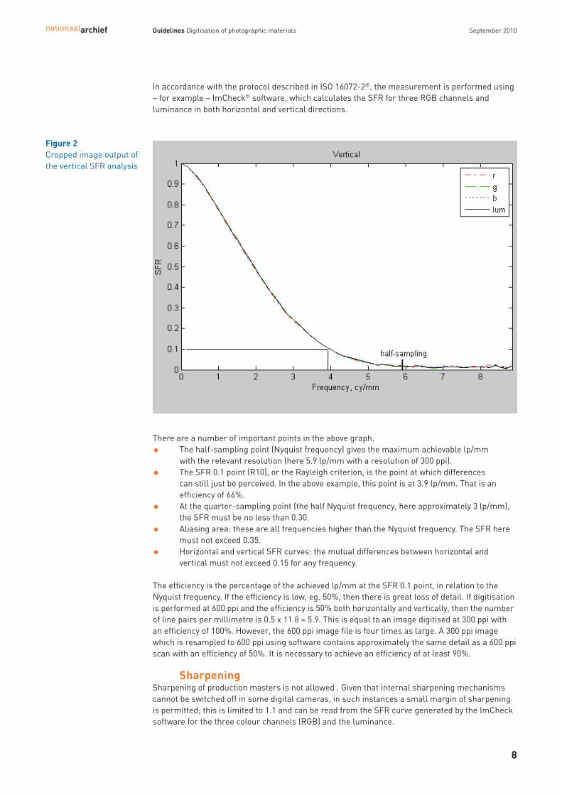
In accordance with the protocol described in ISO 16072-2®, the measurement is performed using– for example – ImCheck© software, which calculates the SFR for three RGB channels andluminance in both horizontal and vertical directions.
There are a number of important points in the above graph.
• The half-sampling point (Nyquist frequency) gives the maximum achievable lp/mm with the relevant resolution (here 5.9 lp/mm with a resolution of 300 ppi).
• The SFR 0.1 point (R10), or the Rayleigh criterion, is the point at which differences can still just be perceived. In the above example, this point is at 3.9 lp/mm. That is anefficiency of 66%.
• At the quarter-sampling point (the half Nyquist frequency, here approximately 3 lp/mm),the SFR must be no less than 0.30.
• Aliasing area: these are all frequencies higher than the Nyquist frequency. The SFR heremust not exceed 0.35.
• Horizontal and vertical SFR curves: the mutual differences between horizontal andvertical must not exceed 0.15 for any frequency.
The efficiency is the percentage of the achieved lp/mm at the SFR 0.1 point, in relation to theNyquist frequency. If the efficiency is low, eg. 50%, then there is great loss of detail. If digitisationis performed at 600 ppi and the efficiency is 50% both horizontally and vertically, then the numberof line pairs per millimetre is 0.5 x 11.8 = 5.9. This is equal to an image digitised at 300 ppi withan efficiency of 100%. However, the 600 ppi image file is four times as large. A 300 ppi imagewhich is resampled to 600 ppi using software contains approximately the same detail as a 600 ppiscan with an efficiency of 50%. It is necessary to achieve an efficiency of at least 90%.
Sharpening Sharpening of production masters is not allowed . Given that internal sharpening mechanismscannot be switched off in some digital cameras, in such instances a small margin of sharpeningis permitted; this is limited to 1.1 and can be read from the SFR curve generated by the ImChecksoftware for the three colour channels (RGB) and the luminance.
Figure 2Cropped image output ofthe vertical SFR analysis

nationaalarchief Guidelines Digitisation of photographic materials September 2010
9
This is visible as the ‘hump’ in the curve in the following example.The digital image is sharpened in the vertical direction to an SFR value of approximately 1.1. For red (r), green (g), blue (b) and luminance (lum), the value is approximately 1.1.
Colour misregistration Colour misregistration arises when the RGB channels do not run entirely synchronously. There isthen a coloured ‘edge’ visible around contrast-rich sections. Colour misregistration can be determined by means of the slanted-edge target and is measuredusing, for example, the ImCheck software. The colour misregistration is determined per colourchannel in both horizontal and vertical directions.
A maximum deviation of ± 0.35 in both the horizontal and the vertical direction is permitted.
0 1 2 3 4 5 6 7 80
0.2
0.4
0.6
0.8
1
half−sampling
Frequency, cy/mm
SF
RVertical
rgblum
Figure 4An example of highcolour misregistration.
Figure 3An SFR graphic.

nationaalarchief Guidelines Digitisation of photographic materials September 2010
10
Digital imaging artefacts Digital imaging artefacts are a set of deviations which share the characteristic that they must beidentified visually. The following artefacts are not permitted.
• Horizontal and vertical stripes.
• Pixellation distortions.
• Halation disturbances.
• Blocking and other deformation defects such as wave motions (moiré) and curving.
• Reflections.
The above list is not exhaustive.
File formatThe file format in which digitisation must be carried out is TIFF version 6.0 uncompressed. The TIFF file must meet the TIFF 6.0 specifications. (see http://partners.adobe.com/public/developer/en/tiff/TIFF6.pdf). The file format for thederivatives is JPEG lossy compression, baseline 1:10.
File names for digital imagesRetaining the link between the digital image and its original is crucially important. That link, andalso those with the associated metadata or signifiers, are guaranteed by including primary infor-mation such as the inventory number and/or photograph number in the file name. This also allowsthe opportunity to add metadata on-screen, based upon the characteristics of the digital images.
Each digital image must have a unique file name. The Contracting Authority determines thenaming format to be used for each (sub)project.
An example of a file name:NL-HaNA_2.24.03_34.tif
This states:Contracting Authority_collection_photograph number.extension
Order of digital images from the source materialThe order of the digital images must comply with the requirements set by the ContractingAuthority, which indicates how they should be sequenced.
Frequency of test scansTest scans are carried out at the start of every production day, after the digitising equipment hasbeen switched off and whenever its hardware or software settings have been changed.
Please refer to the relevant chapters for information on the test targets.
Inspection of test scans It is recommended that measurements be checked immediately after producing the test scans,so that any deviations in the hardware or software can be detected and remedied at an earlystage. The measurement results from the test scans must be submitted together with theprogress reports, and possibly also with the Final Report. The parties are expected to reachagreements on the form in which these results are submitted to the Contracting Authority. This may differ per test scan. See also ‘Inspection by the Contractor’.
Order of test scansThe test scans must be ordered carefully, so as to enable inspection of production quality. Thetarget files must be saved in a separate directory. It is important that there is an unambiguousrelationship between the digital images and their associated Test Scans. The relationship betweenthe test scans and the associated digital images could potentially be determined by a concordance.This must be negotiated with the Contracting Authority and put down in writing.

nationaalarchief Guidelines Digitisation of photographic materials September 2010
11
File names of test scansThe Contracting Authority determines how the test scans are named. The elements to beincorporated in the file names are: the hardware used or the name of the workstation; theresolution; the type of target; and metadata for the source material to be digitised.
The Contracting Authority determines the file naming format to be used for each project.
An example of a file name:Scanner 2_2.24.03_0600_0002_colour.tif
This states:Workstation_collection_resolution_second test cycle for the resolution concerned_targettype.extension
2.5 Logistics
Glass plate negativesBecause of the fragile nature of the material, transportation of glass plate negatives must bekept to a minimum. Consequently, their digitisation takes place at the Contracting Authority.
Air quality and hygiene The relative humidity in the environment where the source materials are located during shipment,storage and processing must be no greater than 65% and no less than 30%. The source materialmust not be exposed to direct or indirect sunlight. The temperature to which source material isexposed must not normally exceed 30° Celsius. During digitisation, however, the temperaturemay occasionally reach 40° C. And during shipment the temperature may reach 35° C for limitedperiods.
Objects must not be stored against an external wall, due to condensation risk, or in the vicinity of radiators or other heat sources. Air quality variations must be limited. Risks such as flooding,fire and burglary must be minimised as much as possible.
Biological threats such as vermin, insects and mould must be prevented as much as possiblethrough best-practice hygiene.
Internal transportThe Contractor guarantees maximum effort to ensure the security of the source material during shipment, processing and at all other times.
After digitisation, the source material is returned to the Contracting Authority in appropriatepackaging.
ShipmentThe Contracting Authority ensures that the photographic material is packed in archive orcomparable boxes. The Contractor is responsible for shipping the source material, and alsomaking it ready for shipment. The following precautions must be taken in this regard.
• Climatic conditions as per requirements.
• Shock and impact-resistant packaging during shipment.
• Shipment in universal, convenient and identical crates, cases or boxes.
• Protection against weather (rain, wind and sun), including during loading and unloading
All costs associated with transportation of the source material are payable by the Contractor.These include:
• costs of transportation;
• costs of packaging;

• insurance;
• valid licences (eg. transportation of dangerous goods), if applicable;
• customs procedures, if applicable;
• import and export duties, if applicable;
• excise duties, if applicable.
The Contractor must collect the source material from the partner organisations in Amsterdamand/or The Hague, and return it after processing, as per the specifications contained in theDescriptive Document. The Contracting Authority advises on the packaging to be used in order to maintain the quality of the transported material.
Delivery of digital files and source materialThe Contractor and the Contracting Authority make agreements concerning the supply of digitalfiles, including any part deliveries. The Contractor ensures temporary back-up of the digital files until one month following approval of the full or part delivery by the Contracting Authority.The Contracting Authority carries out an inspection within two months following delivery.
The digital files must be readable as delivered on the computer hardware used by the ContractingAuthority: Windows PC FAT 32 or NTFS with a master boot record (MBR). The digital files must be supplied on external hard disks with a USB 2.0 connection; the Contracting Authority provideshard disks for this purpose. Any problems regarding the compatibility of plugs and voltages mustbe resolved by the Contractor. The Contracting Authority and the Contractor may decide, aftermutual consultation, on a different method of delivering the files – for instance, by FTP or storageon demand.
A folder containing the number of the collection and the box or inventory number is created for each box or inventory number in which the associated files are to be stored. See also ‘Order of digital images’ and ‘Order of test scans’.
The source material is returned to the Contracting Authority after the digital files have beenapproved.
Property rightsThe Contracting Authority at all times retains ownership of intellectual and physical propertyrights of the source material, and also acquires the full property rights in the digital imagesproduced. The copyright to an image, and in the digital images created from it, is retained withoutprejudice by the relevant copyright holder. The Contractor is not permitted to use digital images, their derivatives or the photographicsource material in any way. The Contractor destroys the digital images, and also any derivatives,one month after they have been approved by the Contracting Authority. Whenever the Contracting Authority requests that files be destroyed, the Contractor is requiredto overwrite them; that is, it must apply a software procedure that replaces the digital imagesand their derivatives with meaningless data. The Contractor agrees only to use overwritingsoftware that (1) is approved by the Contracting Authority and (2) is compatible with the specifichardware intended for overwriting.
Transfer DocumentResponsibility for the photographic material rests with the Contractor throughout shipment,temporary storage and digitisation. Prior to their transfer, the Contracting Authority expects the Contractor to sign a Transfer Document confirming that the source materials have beendelivered in good order and in the agreed quantities (number of boxes, or possibly number ofindividual items). Upon return of the source materials, the Contracting Authority checks thenumber received and their packaging. A confirmation of receipt is then signed if the consignmenthas been received in good order. In the event that quantities are incorrect or damage is found,compensation may be demanded up to a maximum of € 10 per object.
nationaalarchief Guidelines Digitisation of photographic materials September 2010
12

Progress reports on digitisation and project consultationsThe Contractor reports on its progress on a monthly basis. This report clarifies the current stateof affairs, the progress made so far and any particular details. Any significant deviations from the scheduled workflow must be explained.
The method by which the measurement results for the test scans are made available isdetermined in consultation with the Contracting Authority.
Final Report on digitisationAt the end of the digitisation project, the Contractor submits a Final Report to the ContractingAuthority in digital form. This includes the following content and technical information.
Content
• The digitised collection. (The Contracting Authority determines the details to be included here).
• File names from …. to ….. (Several series may be possible).
• Name of the digitising company.
• Year of digitisation.
• Number of digital images.
• Number of source objects.
• Name of the Contracting Authority.
Technical
• Resolution per project section.
• Date of technical inspection (month and year).
• Any outstanding measurement results from the test scans.
• The digitising equipment used (cameras, digital camera backs, etc.)
• The colour temperature of the illumination used, in degrees Kelvin.
• The colour rendition index (CRI) of the illumination used.
The report is submitted in a format agreed with the Contracting Authority.
2.6 Testing
In order to check its ability to fulfil the contract properly, a prospective Contractor is required tocomplete a test following provisional acceptance of its tender. The procedure for this is as follows.
After provisional award has been made but before the Framework Contract is signed, thesuccessful Tenderer (prospective Contractor) must demonstrate that it is able to carry outdigitisation in accordance with the contract. The Tenderer has a total of two months in which to do this. The Contracting Authority makes original photographic material available for thispurpose. This two-month period begins as soon as the Tenderer has received the test targets and software from the Contracting Authority.
Before digitisation can begin, the Tenderer must align and calibrate the necessary equipment.The Contracting Authority submits test targets for this purpose, as well as the software neededin order to conduct measurements on them. Once the illumination uniformity and OECF have been established, the Contracting Authorityassists with further preparations for digitisation. At the same time, the Contracting Authoritymay give brief instructions regarding the test scans, their measurement and the interpretation of the data. Representatives from the Contracting Authority will be available at the site where the Tenderer intends to digitise the source materials for a maximum of five consecutive workingdays. However, this attendance should not be required whilst the equipment is being aligned and calibrated.
nationaalarchief Guidelines Digitisation of photographic materials September 2010
13

Once alignment and calibration are complete, the test scans are made and they and theirmeasurement results are delivered to the Contracting Authority. It is based upon these imagesthat the Contracting Authority determines whether the preparations for digitisation have beencompleted successfully and the measurement results comply with the requirements contained in the Descriptive Document. If the test scans are rejected, the Tenderer is given up to threefurther opportunities to correct the problems, providing it does so within the period available for the test phase.
Following these preparations, the Tenderer digitises sample photographic material in accordancewith the requirements contained in the Descriptive Document. That sample consists of no morethan 25 items, which are supplied by the Contracting Authority. The resulting digital images and their derivatives are delivered to the Contracting Authority along with the test scans and their measurement results. The results are assessed using theprocedure described in the Descriptive Document. If this production sample is rejected, theTenderer is given up to two further opportunities to correct the problems, providing it does sowithin the period available for the test phase.
The Contractor ensures that the original photographic material and – depending upon the award –any test targets are returned to the Contracting Authority in good order. This constitutes a part of the test.
nationaalarchief Guidelines Digitisation of photographic materials September 2010
14

nationaalarchief Guidelines Digitisation of photographic materials September 2010
15
3.1 Results
The Contractor produces digital images of photographic material based upon the requirementscontained in the Descriptive Document. These images are the production masters (TIFF revision6.0 quality) and undergo limited processing; specifically, they are cropped. The basic standard is that, roughly speaking, it should be possible to produce a print of the digitalimage in approximately A4 format, with a resolution of 300 dots per inch (dpi). Given that thesource material varies in format, images with different resolutions are actually produced.A derivative (JPEG baseline compression 1:10) is made of each production master, and bothmasters and derivatives are supplied to the Contracting Authority. Making good test scans, giving correct file names and proper organisation of the digital imagesare all part of the test exercise.
The Contractor ensures temporary back-up of the digital files until one month following approvalof delivered production masters and derivatives by the Contracting Authority. The Contractormust collect the source material from the Contracting Authority and deliver it after processing inaccordance with specifications contained in the Descriptive Document. The partner organisationsadvise on the packaging to be used in order to safeguard material during transportation.
3.2 Specifications for the digitisation of photographic prints
SoftwareIt is strongly advised that the most recent version of any software be used when assessing and, if need be, post-processing images. The Contracting Authority uses the following colour settingsin Abode Photoshop for assessments. (See figure 5 on the next page).
The Contracting Authority uses the following hardware and applications for quality control.
• Monitor: EIZO CG221.
• Eye One spectrophotometer for calibration of the monitor.
• EIZO ColorNavigator for calibration of the monitor.
• Adobe Photoshop CS4 Extended to measure pixel values, pixel value distribution, standard deviation, angle and distance.
• ImCheck (Copyright: Peter D. Burns) to check detail reproduction (SFR), efficiency, noise and colour misregistration. This software is provided by the Contracting Authority.
• IE Analyzer 3.10 Colour Module to check colour reproduction. This software is provided by the Contracting Authority.
Software and test targets made available by the ContractingAuthority
The following software and test targets are made available to the Contractor to check digital images.
• QA-2M test target for geometric distortion
• QA-62 print slanted-edge target (SFRM-OECF).
• GretagMacbeth ColorChecker SG, a colour chart with 140 patches.
• Kodak Q13 Gray Scale, a greyscale with 20 patches.
• IE Analyzer 3.10 Colour Module, software for ΔE measurement.
• ImCheck software for measurements against SFRM-OECF target.
3 Photographic prints, various sizes, black and white, and colour

nationaalarchief Guidelines Digitisation of photographic materials September 2010
16
From Up to and including ppi *) Pixels/mm lp/mm Efficiency1.8 x 2.4 cm ≤ 13 x 18 cm 600 23.6 11.8 90%13 x 18 cm ≤ 18 x 24 cm 450 17.7 8.85 90%18 x 24 cm 30 x 42 cm 300 11.8 5.9 90%Album pages etc. Approx. 22 x 34 cm 450 17.7 8.85 90%
Resolution of print source materialResolution depends upon the format of the source material. In principle, material of 180 x 240 mmor larger is digitised at 300 ppi. For smaller material, digitisation is performed such that thedigital image is at a minimum of 180 mm x 240 mm x 300 ppi. The maximum resolution for printmaterial is 600 ppi, and for transparent material 2400 ppi. Print source material smaller than 13 x 18 cm is digitised at a resolution of 600 ppi. Possible exceptions to the above rule arephotograph albums, album pages and photographs affixed to cardboard. These appear onlyoccasionally. In order to retain their context, the Contracting Authority may decide to digitisethese items in their entirety. And it may be decided to digitise them at 450 ppi because the manysmall photographs on these sheets would be digitised at a relatively lower resolution. The Contracting Authority indicates which items are to be digitised at 450 ppi on a per-project or per-section basis. If the distance to the Source Material is fixed (for instance with flatbedscanners) the principle must be that the Resolution is not interpolated. This will often be theoptical Resolution divided by a positive whole number. The manufacturer will be able to give adefinitive answer to this. If the specifications of the scanner require such action, deviation fromthis may be possible in consultation with the Contracting Authority.
Table 1 shows the resolution for different formats in which items must be digitised. If possible, theContracting Authority supplies the source material sorted according to the required resolution.The Contractor can then work as much as possible with the same hardware and software settings.
Table 1Resolutions for photo-graphic print material.
*) Only non-interpolated resolutions may be used. If the hardware makes this necessary, the next higher non-interpolated resolution should be used. For example 480 ppi instead of 450 ppi.
Figure 5Screenshot from Adobe Photoshop CS4.

Geometric distortion Geometric deformation or distortion occurs in different ways.
• Cushion-shaped distortion: the sides of a square or rectangle are somewhat concave.
• Barrel-shaped distortion: the sides of a square or rectangle are somewhat convex.
• Skew: caused by the recording surface not being parallel to the original.A maximum deviation of 1% is permitted.
For print photographic material, a geometry test target is used for subsequent measurement of the length and height of the digital image – for example, the QA-2M image evaluation testtarget or a similar chart.
Tonal rendition (OECF)The tonal rendition of a digital image is one of the most important technical quality criteria. It is therefore the first parameter to be evaluated in assessing quality. In principle, gammashould be 2.2 across the entire range. The assessment is based upon comparison between the values of the pixels on a greyscale in atest scan with the calculated pixel values of the original physical greyscale. The Kodak Q13 orQ14 Gray Scale, or a comparable scale, is used for the inspection. These have gradations of 0.1D,starting at D = 0.05 and finishing at D = 1.95. All twenty steps are important. The calculatedvalues are listed below with their permitted tolerances.
For rapid evaluation of the quality of the tonal rendition, begin by assessing four patches. If these patches are positively rated, the next 16 can be assessed. The margins are identical for all patches, namely plus or minus 1/12 stop (D = ± 0.025) minus 3 pixel values for the lowestvalue. The difference between the pixel values of patch A and patch 1 in the image is of essentialimportance. This difference is indicated as the highlight gamma. An explanation and the calculation of the highlight gamma are given below. Also stated are thepixel values in the image within which each of the gradations of the greyscale must fall.
Patch A must retain its minimal cover in the digitised image. The margin of illumination in makingthe image is also very slight, because the photographic print density of patch A is so small,namely 0.05. The acceptable illumination margin is 1/6 stop and 3 pixel values in total. Thatmeans 1/12 stop underexposure minus 3 pixel values and 1/12 stop overexposure. This represents0.086 and 0.025 in terms of photographic print density.
The pixel value can be calculated using the reflection value. This value depends upon the colourprofile you are working in, and upon the bit depth and gamma setting of the monitor. In principle,the colour profile to be used is Adobe RGB 1998, the monitor gamma setting 2.2 and the bit depth 8. After conversion, a density of 0.025 results in a pixel value of 248. And density 0.086results in a pixel value of 233. The pixel value of patch A on the greyscale in the image must lie
nationaalarchief Guidelines Digitisation of photographic materials September 2010
17
Figure 6Geometry test target for photographic prints.

between 248 and 233 (see table below). Naturally, a total margin of 1/6 f-stop applies to the pixelvalue of patch 1 and all other patches. The pixel value of patch 1 must be between 224 and 209.The real and theoretical pixel values (without exposure margin) of patches A and 1 respectivelyare 242 and 218.
The highlight gamma is the quotient of the difference in pixel values between patches A and 1 of themeasured pixel values in the image and of the real or theoretical pixel values (measured/theoretical).For example, the difference in the measured pixel values of patches A and 1 in the image is248-220 = 28. The difference in the real or theoretical pixel values between patches A and 1 is242-218 = 24. The quotient of the difference in pixel values between patches A and 1 is now 28:24 = 1.1. And the highlight gamma is 1.1. The highlight gamma may vary in size to some extent;this depends upon the quality of the imaging equipment being used. The acceptable value of thehighlight gamma is between 0.8 and 1.08.
An image of a greyscale is included below for illustrative purposes.
nationaalarchief Guidelines Digitisation of photographic materials September 2010
18
Table 3Pixel values.
Figure 7Example of a greyscale.
Sequence Measured or Acceptableof stages calculated unit values1 Pixel value, patch A 248 - 233 2 Pixel value, patch 1 224 - 2093 Highlight gamma 0.8 - 1.084 Pixel value, patch 9 97 - 895 Pixel value, patch 19 34 - 29
Kodak Density Reflection Theoretical Maximum Minimum Minimum Gray value pixel value permitted permitted permittedscale pixel value pixel value pixel value
(+1/12 stop) (–1/12 stop) – 3 pixel valuesA (0) 0.05 0.891 242 248 236 2331 0.15 0.708 218 224 212 2092 0.25 0.562 196 201 191 1883 0.35 0.447 177 181 172 1694 0.45 0.355 159 163 155 1525 0.55 0.282 143 147 140 1376 0.65 0.224 129 133 126 123M (7) 0.75 0.178 116 119 113 1108 0.85 0.141 105 108 102 999 0.95 0.112 94 97 92 8910 1.05 0.089 85 87 83 8011 1.15 0.071 77 79 75 7212 1.25 0.056 69 71 67 6413 1.35 0.045 62 64 60 5714 1.45 0.035 56 57 54 5115 1.55 0.028 50 52 49 46B (16) 1.65 0.022 45 47 44 4117 1.75 0.018 41 42 40 3718 1.85 0.014 37 38 36 3319 1.95 0.011 33 34 32 29
Table 2Conversion of thegreyscale densities topixel values with theassociated tolerances(monitor gamma = 2.2).

Measuring pixel values The pixel values are measured with a minimum pixel surface setting of 11 x 11 pixels (using the‘eyedropper’ tool in Adobe, for instance). The pixel values are displayed in the information screen.The same colour channel must be used to measure the pixel values and to calculate the highlightgamma in a colour file; it is best to use the channel with the highest pixel values in patch A. In any case the tolerances in pixel values, and therefore also their maximum values, apply to allthree colour channels.
NoiseAs far as possible, scans need to be noise-free. The maximum noise value is 4. Noise can bedescribed as undesirable light fluctuations in an image that do not form part of the sourcematerial. In this respect, the noise may be of a more random or fixed kind. Image noise reductionand noise cleaning processing are not permitted.
Noise can be measured using the greyscale and the slanted-edge software. This calculates the standard deviation (deviation from the average value) in the three RGB channels for eachpatch in the greyscale. The curve shown below is the output in the slanted-edge software. Thestandard deviation values are displayed on the Y axis and the reflection values of the greyscale on the X axis.
Because damage and dirt on the target are measured as a deviation, it is absolutely necessary towork with an undamaged, uncontaminated and dust-free greyscale. If working with a glass plate,this must be clean and scratch-free. The maximum permitted amount of noise is a standard deviation of 4. This figure is based uponthe visibility of noise in the image. The acceptable amount of noise in an image is related to thevisual experience; it must not (or only barely) be visible, even in darker areas.
nationaalarchief Guidelines Digitisation of photographic materials September 2010
19
40 60 80 100 120 140 160 180 200 220 2400
0.5
1
1.5
2
2.5
3
3.5
4
Signal
RM
S n
oise
Total Noise [0, 255 scale]
rgblum
Figure 8Noise curve fromslanted-edge software.

nationaalarchief Guidelines Digitisation of photographic materials September 2010
20
Signal-to-noise ratio (SNR) The SNR gives an insight into the relationship between pixel values (‘signal’) and the noise value.It can be calculated by dividing the pixel value of a random patch on the greyscale by thecorresponding noise value or standard deviation. The standard deviation can be read from thehistogram. If, for example, the pixel value of patch 19 is 33 and the noise value is 3, then the SNR33:3 = 11. This means that 1/11 (or 9%) of patch 19 consists of noise. So the higher the SNR, thebetter the ratio between noise and signal.
The SNR must not be less than 6 for any pixel value of a random patch on the greyscale. If 1/6 ormore of an image is noise, then that amount is so great that it detracts from the visual experience.The SNR and the associated input density give the dynamic range of the scanning or camera system.
The above method is that currently used for print material. Should a better one be developed inthe future, the Contracting Authority will adopt that instead.
Illumination uniformity In order to guarantee even and uniform illumination, a piece of white cardboard must be includedas an image filler. This should have an input density between 0.05 and 0.15. A Kodak or comparablegreyscale must also be included in the centre base of the image. In order to assess the uniformillumination (with image processing software such as Photoshop), the pixel value must bemeasured at no fewer than five points using the eyedropper tool, with a minimum surface settingof 11 x 11 pixels. The measuring points are in the centre and at the four corners. If there is anydoubt about the quality of the illumination uniformity, more points must be measured.
The difference between pixel values across the image surface must not be greater thanapproximately 8 per colour channel. This corresponds to a difference in input density of 1/10 f-stop. The maximum pixel value must not exceed 250.
It is possible that the optical whiteners in the cardboard will result in an incorrect or somewhatdeviating ratio of pixel values between the three colour channels. This method is therefore notsuitable for assessing colour cast. It is also possible that the optical whiteners will result in anincorrect or somewhat deviating conversion of reflection values into pixel values. It is therefore notadvisable to compare reflection and pixel values one to one by the use of white card or paper withoptical whiteners, or to perform a one-to-one pixel value comparison of such cardboard or paperwith the pixel values of test targets like the Kodak Q13 and the GretagMacbeth ColorChecker SG.
White cardboard or paper will, however, provide only a general impression as to whether theillumination uniformity and colour cast are correct or incorrect. The rule on 8 pixel values musttherefore be applied with some discretion .
Colour castJust as with illumination uniformity, the potential colour cast needs to be measured and assessedin the centre and at the corners of the total image plane. The maximum permitted colour cast is + 3 and - 3 pixel values difference between the three colour channels per grey patch.
Colour accuracy In order to guarantee colour accuracy, images are to be taken of a standardised colour chart with140 patches – for example, the GretagMacbeth ColorChecker SG or similar. Using software, thecolours obtained are then compared with their reference values. The Contracting Authority usesthe package IE Analyzer 3.10 for this purpose.
The comparison is made in colour area LAB and then in ΔE. The specifications against which the colour is assessed are hue (tint), chroma (colour saturation) and luminance (clarity). Criteriahave been drawn up for all three. The acceptable value for colour deviations is an average ΔE ofless than 6 with a maximum of less than 15.

The Contracting Authority applies the following basis technique: the measurements are taken in IE Analyzer, in accordance with CIE1976; the white point is ‘profile’; and the RGB is convertedinto LAB using Adobe RGB1998.
ModeFor the colour digitisation of black and white photographic prints, use the following modesettings.
• Colour: 24 bits.
• Colour space: ICC profile Adobe RGB 1998.
For monochrome digitisation, use the following settings.
• Greyscale values: 8 bits.
• Colour space: ICC profile greyscale values gamma 2.2.
The Contracting Authority indicates on per-project, per-archive or per-section basis whetherblack and white photographic prints are to be digitised in colour or using greyscale values.
For the digitisation of colour photographic prints, use the following mode settings.
• Colour: 24 bits.
• Colour space: ICC profile Adobe RGB 1998.
Image structure and sequence of test scansExposure 1:Illumination uniformityA clean, smooth piece of white cardboard must be included as image filler, with an input densitybetween 0.05 and 0.15. A Kodak or comparable greyscale must also be included, in the centre orat the bottom of the image. The distance between the cardboard and the lens must be the sameas between the source material and the lens during production.
In other words, the reduction factor and resolution used for the test targets must be identical to those used for the exposure of actual source material. This applies to all test targets.
The current greyscale has a Dmax of 1.95. As soon as a suitable scale with a higher Dmax(2.15-2.30) becomes available, that must be used.
Exposure 2: Tonal capture, colour cast and colour accuracyThese items are assessed from a single image. A piece of white cardboard must be included asan image filler, with an input density between 0.05 and 0.15. There must be a colour card at thecentre of the image: the GretagMacbeth ColorChecker SG or a comparable chart. And a Kodak or comparable greyscale must also be included, in the centre or at the bottom of the image. For resolution details, see exposure 1.
Exposure 3: SharpnessA black background must be included as an image filler. There are slanted-edge test targets inthe centre and at corners of the image. It is important that these be positioned correctly and that they are straight in relation to the image area. A Kodak or comparable greyscale must alsobe included, in the centre or at the bottom of the image For resolution details, see exposure 1.
Exposure 4: Optical distortion and deformation. A black background must be included as image filler. There is a QA-2M geometry test target in the centre of the image. This is in A3 format, but can also be used for A4 and A5. Research is being done to find a Test Target for small Source Material. Resolution: refer to exposure 1. For resolution details, see exposure 1.
nationaalarchief Guidelines Digitisation of photographic materials September 2010
21

Imaging method The photographic prints are exposed against a black background, which may have contrastinghorizontal and vertical lines as an aid to keep the source material straight.
Digitisation of photo albums, album pages and photographs affixed to cardboard
From time to time, photo albums, album pages and photographs affixed to cardboard need to bedigitised. In these cases, depending upon the context it may be necessary to digitise entire pagesor cards. A higher resolution may be desirable in such instances.
nationaalarchief Guidelines Digitisation of photographic materials September 2010
22
Figure 9Example of an albumpage (top) and of aphotograph affixed tocardboard (bottom).

Other deviations When bound Source Material is digitised, every effort must be made to prevent that letters in thespine fold become illegible or disappear into the shadow. It is essential to consult the ContractingAuthority if this proves to be unavoidable.
3.3 Post-processing digital images of photographic prints
RotationDigital images may be rotated in multiples of 90o only, using Adobe Photoshop or similar software.No interpolation of pixels is allowed during this rotation.
AlignmentIt is not permitted to straighten images digitally. An alignment deviation of 0.5 degrees ispermitted.
CroppingCropping entails cutting out the relevant part of a digital image and discarding the irrelevant part.This must be done in such a way that the entire original remains visible, with a small borderaround it.
3.4 Inspection by the Contractor
nationaalarchief Guidelines Digitisation of photographic materials September 2010
23
Table 4Inspection by the Contractor
Target used Recommended Measurement Results Text reference software
Frequency of test scans (2.4)Order of test scans (2.4)File names of test scans (2.4)Image structure and sequence of test scans (3.2)
Slanted-edge target ImCheck SFR efficiency Efficiency min. 90% SFR/detail reproduction (2.4)Slanted-edge target ImCheck SFR aliasing SFR on Nyquist frequency SFR/detail reproduction (2.4)
should not exceed 0.35Slanted-edge target ImCheck SFR at 1/4 sampling SFR at 1/4 sampling frequency SFR/detail reproduction (2.4)
frequency should be no less than 0.30Slanted-edge target ImCheck SFR mutual Mutual difference in SFR between SFR/detail reproduction (2.4)
difference horizontal and vertical should notexceed 0.15. Curves must not display strong troughs or peaks prior to the Nyquist frequency.
Slanted-edge target ImCheck SFR/sharpening Max. 1.1 Sharpening (2.4)Slanted-edge target ImCheck Colour misregistration Max. 0.35 pixels Colour misregistration (2.4)Geometry test target Image processing Geometric distortion Max. 1% Geometric distortion (3.2)
softwareGreyscale Image processing Tonal rendition See text Tonal rendition /
software measuring pixel values (3.2)Greyscale ImCheck Noise Max. 4 Noise (3.2)White paper Image processing Illumination See text Illumination uniformity (3.2)+ greyscale software uniformityGreyscale Image processing Colour cast Mutual difference Colour cast (3.2)
software max. +/– 3 pixel valuesColour chart IE Analyzer Colour reproduction Average ΔE < 6. Max. ΔE < 15 Colour accuracy (3.2)Greyscale ImCheck / Image SNR Min. 6 Signal-to-noise ratio (3.2)
processing software

The Contractor inspects both test scans and the digital images for completeness and quality in accordance with the requirements set. The checks on the test scans are based upon of theproduction masters.
See table 4 for a summary of the required measurements for the test scans for prints, ascontained in the Descriptive Document. This lists the target used, the software recommended formeasurement, the results required and a reference to the location of detailed information in the text.
The Contracting Authority provides the following targets and measurement software.
• QA-2M test target for geometric distortion
• QA-62 print slanted-edge target (SFRM-OECF).
• GretagMacbeth ColorChecker SG, a colour chart with 140 patches.
• Kodak Q13 Gray Scale, a greyscale with 20 patches.
• IE Analyzer 3.10 Colour Module, software for ΔE measurement.
• ImCheck software for measurements against SFRM-OECF and greyscale targets.
It is recommended that the technical targets be checked immediately after recording, so that any deviations in the hardware or software can be detected and remedied at an early stage. Themeasurement results are submitted to the Contracting Authority. The Contractor also inspects the digital images for quality and completeness. Should anydeviations be detected, the Contractor must inspect the images using the production masters.Once the Contractor has approved them for quality and completeness, the images can besubmitted to the Contracting Authority.
3.5 Inspection by the Contracting Authority
Digitisation begins with a test phase. The Contracting Authority is entitled to be present on-siteat this stage in the process. Based upon the measurements obtained from the test targets andvisual assessment of the digital images and source material, a decision can then be made as towhether to proceed with production.
After a full or partial delivery has been made, a production check is performed prior to its formalacceptance by the Contracting Authority.
The Contractor makes the test scans and their measurement results available to the ContractingAuthority (see ‘Inspection by the Contractor’), which checks them. If they do not meet therequirements set, the entire production batch with which they are associated is rejected.
Individual images are also inspected, with random samples taken of production masters. The sizes of these samples per batch are derived from ISO 2859-1: 1999, “Sampling proceduresfor inspection by attributes – part 1: sampling schemes indexed by acceptable quality level (AQL)for lot-by-lot inspection.”
nationaalarchief Guidelines Digitisation of photographic materials September 2010
24
General test level II Quality level IBatch size Random Accepted Rejected Letter
sample size Number Numberof errors of errors
281-500 50 ≤ 1 ≥ 2 H500-1200 80 ≤ 2 ≥ 3 J1201-3200 125 ≤ 3 ≥ 4 K3201-10000 200 ≤ 5 ≥ 6 L10001-35000 315 ≤ 7 ≥ 8 M35001-150000 500 ≤ 10 ≥ 11 N
Table 5Random sample sizes, general test level II.

The inspection is based upon the following parameters.
• The size of the random sample must comply with general test level II.
• The acceptable quality level (normal test) is 1.0.
For the random sample sizes and tolerance of errors at general test level II, as per ISO 2859-1,see table 5.
If overall production quality proves to be good, it is possible to change to inspection at generaltest level I. This provides for the following random sample sizes and tolerance of errors, again asper ISO 2859-1.
If the acceptable number of errors for a particular batch is exceeded, it is rejected in its entirety.If a batch is rejected after inspection at general test level I, subsequent inspections revert togeneral test level II.
The Contracting Authority retains the right to carry out more inspections than described above.
Errors must be remedied and redigitisation completed within the time limit agreed for the full or part project.
As well as checking production, the Contracting Authority also inspects the source material for completeness and damage. In the event that quantities are incorrect or damage is found,compensation may be demanded up to a maximum of € 10 per object.
The table on the next page lists the aspects subject to inspection by the Contracting Authority,with the acceptable tolerances and the action to be taken if these are exceeded. All errorsdetected upon inspection must be remedied by the Contractor.
nationaalarchief Guidelines Digitisation of photographic materials September 2010
25
Table 6Random sample sizes,general test level I.
General test level I Quality level IBatch size Random Accepted Rejected Letter
sample size Number Numberof errors of errors
281-500 20 ≤ 0 ≥ 1 F500-1200 32 ≤ 1 ≥ 2 G1201-3200 50 ≤ 1 ≥ 2 H3201-10000 80 ≤ 2 ≥ 3 J10001-35000 125 ≤ 3 ≥ 4 K35001-150000 200 ≤ 5 ≥ 6 L
nationaalarchief Guidelines Digitisation of photographic materials September 2010
26
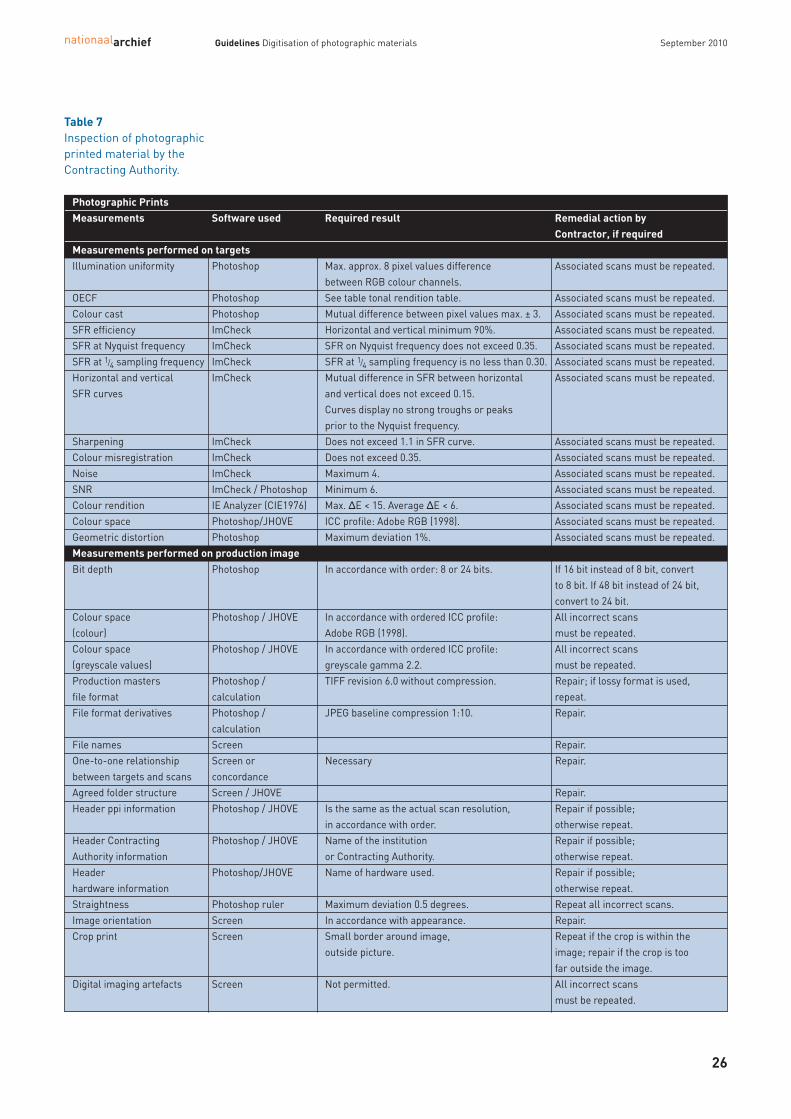
Table 7Inspection of photographicprinted material by theContracting Authority.
Photographic PrintsMeasurements Software used Required result Remedial action by
Contractor, if requiredMeasurements performed on targetsIllumination uniformity Photoshop Max. approx. 8 pixel values difference Associated scans must be repeated.
between RGB colour channels.OECF Photoshop See table tonal rendition table. Associated scans must be repeated. Colour cast Photoshop Mutual difference between pixel values max. ± 3. Associated scans must be repeated. SFR efficiency ImCheck Horizontal and vertical minimum 90%. Associated scans must be repeated. SFR at Nyquist frequency ImCheck SFR on Nyquist frequency does not exceed 0.35. Associated scans must be repeated. SFR at 1/4 sampling frequency ImCheck SFR at 1/4 sampling frequency is no less than 0.30. Associated scans must be repeated. Horizontal and vertical ImCheck Mutual difference in SFR between horizontal Associated scans must be repeated. SFR curves and vertical does not exceed 0.15.
Curves display no strong troughs or peaks prior to the Nyquist frequency.
Sharpening ImCheck Does not exceed 1.1 in SFR curve. Associated scans must be repeated.Colour misregistration ImCheck Does not exceed 0.35. Associated scans must be repeated. Noise ImCheck Maximum 4. Associated scans must be repeated. SNR ImCheck / Photoshop Minimum 6. Associated scans must be repeated. Colour rendition IE Analyzer (CIE1976) Max. ΔE < 15. Average ΔE < 6. Associated scans must be repeated. Colour space Photoshop/JHOVE ICC profile: Adobe RGB (1998). Associated scans must be repeated. Geometric distortion Photoshop Maximum deviation 1%. Associated scans must be repeated.Measurements performed on production imagesBit depth Photoshop In accordance with order: 8 or 24 bits. If 16 bit instead of 8 bit, convert
to 8 bit. If 48 bit instead of 24 bit,convert to 24 bit.
Colour space Photoshop / JHOVE In accordance with ordered ICC profile: All incorrect scans (colour) Adobe RGB (1998). must be repeated.Colour space Photoshop / JHOVE In accordance with ordered ICC profile: All incorrect scans (greyscale values) greyscale gamma 2.2. must be repeated.Production masters Photoshop / TIFF revision 6.0 without compression. Repair; if lossy format is used,file format calculation repeat.File format derivatives Photoshop / JPEG baseline compression 1:10. Repair.
calculationFile names Screen Repair.One-to-one relationship Screen or Necessary Repair.between targets and scans concordanceAgreed folder structure Screen / JHOVE Repair.Header ppi information Photoshop / JHOVE Is the same as the actual scan resolution, Repair if possible;
in accordance with order. otherwise repeat.Header Contracting Photoshop / JHOVE Name of the institution Repair if possible; Authority information or Contracting Authority. otherwise repeat.Header Photoshop/JHOVE Name of hardware used. Repair if possible; hardware information otherwise repeat.Straightness Photoshop ruler Maximum deviation 0.5 degrees. Repeat all incorrect scans.Image orientation Screen In accordance with appearance. Repair.Crop print Screen Small border around image, Repeat if the crop is within the
outside picture. image; repair if the crop is too far outside the image.
Digital imaging artefacts Screen Not permitted. All incorrect scans must be repeated.
4.1 Results
The Contractor produces digital images of photographic material based upon the requirementscontained in the Descriptive Document. These images are the production masters (TIFF revision6.0 quality) and will be subjected to limited processing; specifically, they are inverted andcropped, the black point and white point are set correctly and the gamma value and contrastcurve are adjusted to provide a good rendition of tone and contrast.
A derivative (JPEG baseline compression 1:10) is made of each production master, and bothmasters and derivatives are supplied to the Contracting Authority. Making test scans, givingcorrect file names and proper organisation of the digital images are all part of the tenderexercise. The Contractor ensures temporary back-up of the digital files until one month followingapproval of delivered production masters and derivatives by the Contracting Authority.
The Contractor must collect the source material from the Contracting Authority and deliver it after processing in accordance with specifications contained in the Descriptive Document. The partner organisations advise on the packaging to be used in order to safeguard materialduring transportation.
Because of the fragile nature of the material, transportation of glass plate negatives must bekept to a minimum. Consequently, their digitisation takes place at the Contracting Authority.
See the relevant sections below for additional information.
4.2 Specifications for the digitisation of transparent objects
IntroductionA number of parameters are quite easily defined in the case of printed material.The maximum reflection (Dmin) and maximum black (Dmax) are givens. The white of aphotograph has a density Dmin of approximately 0.05 and the black of a high-gloss photographmay have a density Dmax of approximately 2.1. When digitising printed material, it is possible toadjust the tonal rendition (OECF) in such a way that the various densities are transposed correctlyto pixel values. The gamma of the digital file will be more or less equal to that of the original. By this method, a relatively faithful digital copy of the original is created.
This is not the case with negatives. They are an intermediate product intended to be used in theprocess of printing on paper. In general, they have a gamma lower than 1. However, this value isnot fixed and the ‘ideal’ gamma has become lower and lower over the years. A gamma of 0.70was considered to be the optimum for a good print off in the 1970s, but 0.55 had become thestandard by the 1990s. Analogue photographers had multicontrast printing paper or paper ofdifferent grades at their disposal to make good prints from negatives with either a higher orlower gamma.
The minimum density of an overexposed or fogged negative, for instance, can be relatively high.The maximum density can also vary enormously, from a Dmax of 0.5 for an underexposed orunderdeveloped negative up to 3.0 for, say, a glass negative or a lantern slide. Negatives must be digitised as if they are positive transparencies, then inverted to obtain apositive image. Because the gamma of a negative is in general lower – much lower, even – than 1,
nationaalarchief Guidelines Digitisation of photographic materials September 2010
27
4 Film-based negatives and glass plate negatives, various sizes, black and white

this produces only a feeble grey positive image. Post-digitisation manipulation of the invertednegative is therefore needed in order to obtain a positive image with good tonal distribution andcontrast. See also ‘Post-processing’.
SoftwareIt is strongly advised that the most recent version of any software be used when assessing and, if need be, post-processing images. The Contracting Authority uses the following colour settingsin Abode Photoshop for assessments:
The Contracting Authority uses the following hardware and applications for quality control.
• Monitor: EIZO CG221.
• Eye One spectrophotometer for calibration of the monitor.
• EIZO ColorNavigator for calibration of the monitor.
• Adobe Photoshop CS4 Extended to measure pixel values, pixel value distribution, standard deviation, angle and distance.
• ImCheck (Copyright: Image Science Associates) to check detail reproduction (SFR),efficiency, noise, DNR, illumination uniformity and colour misregistration. This software is made available by the Contracting Authority.
Software and test targets made available by the Contracting Authority
The following software and test targets are made available to the Contractor to check digital images.
• Applied Image ST-53, a DNR target compliant with ISO 21550 (D = 4.0).
• Nationaal Archief test target for geometric distortion.
• Transparent slanted-edge target (SFRM-OECF).
• Neutral density (ND) filter to determine illumination uniformity.
• ImCheck software to measure SFR, DNR, illumination uniformity and colour misregistration.
nationaalarchief Guidelines Digitisation of photographic materials September 2010
28
Figure 10Screenshot from Adobe Photoshop CS4.

Resolution of transparent source materialResolution depends upon the format of the source material. In principle, material of 180 x 240 mmor larger is digitised at 300 ppi. For smaller material, digitisation is performed such that the digitalimage is at a minimum of 180 mm x 240 mm x 300 ppi. The maximum resolution for transparentobjects is 2400 ppi.
If the distance to the source material is fixed (as with a flatbed scanner, for instance), the principleapplied is that the resolution is not interpolated. In other words, it is often the optical resolutiondivided by a positive whole number; the equipment manufacturer can state whether of not this isthe case. If the scanner specifications require such action, deviation may be possible in consultationwith the Contracting Authority.
The table below shows the resolution for different formats in which items must be digitised. Ifpossible, the Contracting Authority supplies the source material sorted according to the requiredresolution. The Contractor can then work as much as possible with the same hardware andsoftware settings.
Geometric distortion Geometric deformation or distortion occurs in different ways.
• Cushion-shaped distortion: the sides of a square or rectangle are somewhat concave.
• Barrel-shaped distortion: the sides of a square or rectangle are somewhat convex.
• Skew: caused by the recording surface not being parallel to the original.A maximum deviation of 1% is permitted.
A test target must be used to inspect the degree of geometric distortion. This is provided by theNationaal Archief.
ClippingClipping occurs when the minimum and/or maximum pixel values are achieved prematurelyduring the digital image processing. This causes loss of information into the shadows and highlights. On the next page is an example of clipping on the ISO 21550 test target. The squaresadjacent to the cut-out patch (bottom right) have the same pixel value as that square.
nationaalarchief Guidelines Digitisation of photographic materials September 2010
29
Figure 11Nationaal Archieftransparent test targetfor geometric distortion
From Up to and including ppi *) Pixels/mm lp/mm Efficiency1.8 x 2.4 cm ≤ 4 x 4 cm 2400 94.5 47.2 90%4 x 4 cm ≤ 9 x 12 cm 1200 47.2 23.6 90%9 x 12 cm ≤ 13 x 18 cm 600 23.6 11.8 90%13 x 18 cm ≤ 18 x 24 cm 450 17.7 8.9 90%18 x 24 cm 30 x 42 cm 300 11.8 5.9 90%
Table 8Resolutions fortransparent objects.
*) Only non-interpolated resolutions may be used. If the hardware makes this necessary, the nexthigher non-interpolated resolution should be used. For example 480 ppi instead of 450 ppi

Clipping of relevant image information (so not including hotspots or dust particles) is notpermitted. Below are examples of clipped photographic greyscale prints. The pixel value of patch M is the same in both.
A hotspot arises when, for instance, bright sunlight emits into the shot or artificial lighting shinesinto the camera in an evening photograph. Hotspots and dust particles have a relatively high localdensity on a source negative. However, hotspots have a very low local density and dust particles avery high local density on source transparencies or lantern slides.
nationaalarchief Guidelines Digitisation of photographic materials September 2010
30
This patch is cut out to obtaina density of D = 0.
Figure 12Clipping in the ISO 21550Test Target
Figure 13Clipping of the darksections (top) and thelight sections (below).

Illumination uniformityIn order to guarantee even and uniform illumination, a neutral density (ND) filter with a density of D = 0.15 must be included to fill the entire format. The exposure must be selected in such away that the pixel value is between 212 and 235. The maximum pixel value is 240. To assess uniform illumination, the pixel value must bemeasured, using ImCheck, at no fewer than five points: in the centre and at the four corners. If there is any doubt about the quality of the illumination uniformity, more points must bemeasured or the light distribution assessed. The difference between pixel values must notexceed approximately 8 per colour channel.
Transparent film or the ND filter will provide only a general impression as to whether theillumination uniformity is correct or incorrect. The rule on 8 pixel values must therefore beapplied with some discretion..
Dynamic range Dynamic range (DNR) is measured using a modified protocol of ISO 21550, which is incorporatedin the ImCheck software provided. Minimum density range should be 3.0 (1000:1), using a signal-to-noise ratio (SNR) criterion of 3.0. The test target used must conform to ISO 21550:2004(E)©
(see fig. 1 and ISO21550:2004 Photography - Electronic scanners for photographic images - DynamicRange measurements at www.iso.org) – as do the Applied Image ST-53 and the Esser TE 240 –with a contrast range of 10,000:1 (D = 4.0). The resolution is similar to that of the digital images.Image noise reduction and noise cleaning processing are not permitted.
nationaalarchief Guidelines Digitisation of photographic materials September 2010
31
Figure 14Images with hotspots(left) and the hotspotspicked out (right).

Signal-to-noise ratio (SNR) The SNR gives an insight into the relationship between pixel value (‘signal’) and the noise value,based upon a greyscale. ‘Incremental gain’ – involving the comparison of two adjacent squares –must be used in the calculation (See ISO 15739, Electronic still picture imaging – noise measurements;and ISO 21550, Photography – electronic scanners for photographic images – dynamic rangemeasurements). SNR is determined in accordance with ISO 21550. The required minimum SNRfor this section of the project is 3.0.
nationaalarchief Guidelines Digitisation of photographic materials September 2010
32
0 0.5 1 1.5 2 2.5 3 3.5 410
−2
10−1
100
101
102
Target density
raw
SN
R
DNR
rgblum
Figure 15Example of the DNR measurementinformation presented in ImCheck.
Figure 16Example of an ISO 21550DNR target.

Image structure and sequence of test scans A number of test targets for transparent objects are available only in miniature format (24 x 36 mm). When larger source material is digitised, five 35mm-format targets must be placed on the scanner as shown below: one at each corner and one in the centre.
• All transparent test targets must be exposed positively in RGB; they must not be inverted and/or converted to greyscale values.
Exposure 1: Illumination uniformityAn exposure is made of a filter with a density of 0.15. The pixel values must be between 212 and235. The maximum permissible difference is approximately 8 pixel values. The distance betweenthe test target and the lens must be the same as between the source material and the lensduring production. In other words, the resolution used for the technical targets must be identicalto those used for the exposure of actual source material. This applies to all technical targets.
Exposure 2: Dynamic range and noiseAn exposure is made of the centre of the image of an ISO 21550 transmission test target (eg. TE240),with a contrast scope of 10,000:1. The test target must be masked in order to prevent bloomingor light overspill. The required dynamic range of 3 must be achieved. For resolution details, seeexposure 1.
Exposure 3: Sharpness, colour misregistration and efficiency. An exposure is made of the transparent slanted-edge test target. The required sharpness (SFR),colour misregistration, uniformity between horizontal and vertical SFR, SFR on the Nyquistfrequency, SFR at the 1/4 sampling point and efficiency must all be achieved. For resolutiondetails, see exposure 1.
Exposure 4: Optical distortion and deformation. An exposure is made of a suitable geometry test target. For resolution details, see exposure 1.
Mode For the digitisation of transparent material, always use the following mode settings.
• Colour: 48 bits.
• Colour space: ICC profile Adobe RGB 1998.
• Bit depth: 16 bits per colour channel.
The processed digital black and white images are filed in the following modes.
nationaalarchief Guidelines Digitisation of photographic materials September 2010
33
Figure 17Positioning of five small test targets when a 4”x 5” transparentobject is to be digitised.
Top left
Centre
Top right
Bottom left Bottom right

nationaalarchief Guidelines Digitisation of photographic materials September 2010
34
Black and white negatives.
• Greyscale values: 8 bits.
• Colour space: ICC profile greyscale values gamma 2.2.
Black and white negatives, glass plate negatives and lantern slides.
• Greyscale values: 16 bits.
• Colour space: ICC profile greyscale values gamma 2.2.
The Contracting Authority will indicate per project, archive or section whether the digital images are to be supplied in 8-bit or 16-bit mode.
4.3 Post-processing digital images of transparent objects
Producing a positive image from a negativeThe digital images are inverted to produce a positive image. The black point and white point mustbe set properly after cropping, with black no lower than 13 and white no higher than 250. Thegamma and contrast value should then be adjusted to produce a good tonal rendition and contrast.
The Contractor must use the verification exposures provided by the Contracting Authorities as a guide in determining the correct rendition of tone and contrast.
RotationDigital images may be rotated in multiples of 90o only, using Adobe Photoshop or similarsoftware. No interpolation of pixels is allowed during this rotation.
AlignmentIt is not permitted to straighten images digitally. An alignment deviation of 0.5 degrees is permitted.
CroppingCropping entails cutting out the relevant part of a digital image and discarding the irrelevant part.In the case of transparent source material, tight cropping occurs within the image and masksmay be used during digitisation.
4.4 Inspection by the Contractor
The Contractor inspects the digital images for completeness and quality in accordance with therequirements set. Measurements of the test targets are based upon the TIFFs. Table 9 summarises those required in the case of transparent objects, as previously outlined. It states the target used, the software recommended for measurement, the results required and a reference to the location of detailed information in the text.
The Contracting Authority provides the following targets and measuring software.
• Applied Image ST-53, a DNR target compliant with ISO 21550 (D = 4.0).
• Nationaal Archief test target for geometric distortion.
• Transparent slanted-edge target (SFRM-OECF).
• Neutral density (ND) filter D = 0.15 to determine illumination uniformity.
• ImCheck software to measure SFR, efficiency, OECF, DNR, colour misregistration, noise and illumination uniformity.
It is recommended that the technical targets be checked immediately after exposure, so that any deviations in the hardware or software can be detected and remedied at an early stage. The measurement results are submitted to the Contracting Authority.
The Contractor also inspects the digital images for quality and completeness. Once it has approvedthem on those counts, they can be submitted to the Contracting Authority.

4.5 Inspection by the Contracting Authority
Digitisation begins with a test phase. The Contracting Authority is entitled to be present on-siteat this stage in the process. Based upon the measurements obtained from the test scans andvisual assessment of the digital images and source material, a decision can then be made as towhether to proceed with production.
The Contractor makes the test scans and their measurement results available to the ContractingAuthority (see ‘Inspection by the Contractor’), which checks them. If they do not meet therequirements set, the entire production batch with which they are associated is rejected.
Individual images are also inspected, with random samples taken of production masters. The sizes of these samples per batch and the assessment criteria used are derived from ISO 2859-1: 1999, “Sampling procedures for inspection by attributes – part 1: sampling schemesindexed by acceptance quality limit (AQL) for lot-by-lot inspection.”
The inspection is based upon the following parameters.
• The size of the random sample must comply with general test level II.
• The acceptable quality level (normal test) is 1.0.
See the table on the next page for the random sample sizes and tolerance of errors at generaltest level II, as per ISO 2859-1 .
nationaalarchief Guidelines Digitisation of photographic materials September 2010
35
Table 9Inspection by the Contractor.
Target used Measurement Results Text reference Frequency of test scans (2.4)Order of test scans (2.4)File names of test scans (2.4)Image structure and sequence of test scans (4.2)
Transparent slanted- SFR Min. 90%. SFR/detail reproduction (2.4)edge target (SFRM-OECF)Transparent slanted- SFR SFR on Nyquist frequency SFR/detail reproduction (2.4)edge target (SFRM-OECF) should not exceed 0.35Transparent slanted- SFR SFR at 1/4 sampling frequency SFR/detail reproduction (2.4)edge target (SFRM-OECF) should be no less than 0.30.Transparent slanted- SFR Mutual difference in SFR between horizontal SFR/detail reproduction (2.4)edge target (SFRM-OECF) and vertical should not exceed 0.15. Curves
must not display strong troughs or peaks prior to the Nyquist frequency.
Transparent slanted- SFR/sharpening Max. 1.1 Sharpening (2.4)edge target (SFRM-OECF)Transparent slanted- Colour Max. 0.35 pixels Colour misregistration (2.4)edge target (SFRM-OECF) misregistrationNA geometry test target Geometric distortion Max. 1% Geometric distortion (4.2)NA test target Illumination See text Illumination uniformity (4.2) or filter D = 0.15 Uniformity DNR target compliant DNR Should be no less than 3.0 Dynamic range (4.2)with ISO 21550DNR target compliant Clipping See text Clipping (4.2)with ISO 21550

If overall production quality proves to be good, it is possible to change to inspection at generaltest level I. This provides for the following random sample sizes and tolerance of errors, again as per ISO 2859-1.
If the acceptable number of errors for a particular batch is exceeded, it is rejected in its entirety.If a batch is rejected after inspection at general test level I, subsequent inspections revert togeneral test level II.
The Contracting Authority retains the right to carry out more inspections than described above.
Errors must be remedied and redigitisation completed within the time limit agreed for the full or part project.
As well as checking production, the Contracting Authority also inspects the source material for completeness and damage. In the event that quantities are incorrect or damage is found,compensation may be demanded up to a maximum of € 10 per object.
The table on the next page lists the aspects of transparent material subject to inspection by the Contracting Authority, with the acceptable tolerances and the action to be taken if these are exceeded. All errors detected upon inspection must be remedied by the Contractor.
nationaalarchief Guidelines Digitisation of photographic materials September 2010
36
General test level II Quality level IBatch size Random Accepted Rejected Letter
sample size Number Numberof errors of errors
281-500 50 ≤ 1 ≥ 2 H500-1200 80 ≤ 2 ≥ 3 J1201-3200 125 ≤ 3 ≥ 4 K3201-10000 200 ≤ 5 ≥ 6 L10001-35000 315 ≤ 7 ≥ 8 M35001-150000 500 ≤ 10 ≥ 11 N
Table 10Random sample sizes,general test level II.
General test level I Quality level IBatch size Random Accepted Rejected Letter
sample size Number Numberof errors of errors
281-500 20 ≤ 0 ≥ 1 F500-1200 32 ≤ 1 ≥ 2 G1201-3200 50 ≤ 1 ≥ 2 H3201-10000 80 ≤ 2 ≥ 3 J10001-35000 125 ≤ 3 ≥ 4 K35001-150000 200 ≤ 5 ≥ 6 L
Table 11Random sample sizes,general test level I.

nationaalarchief Guidelines Digitisation of photographic materials September 2010
37
The measurements in the upper part of the table below must be performed on images of targets. Those in the lower part of the table will be performed on production images.
Table 12Inspection of transparentmaterial by theContracting Authority.
Transparent ObjectsMeasurements Software used Required result Remedial action by
Contractor, if requiredMeasurements performed on targetsIllumination uniformity ImCheck Max. approx. 8 pixel values difference Associated scans must be repeated.
between RGB colour channels.SFR ImCheck Minimum efficiency is 90%. Associated scans must be repeated. SFR ImCheck SFR on Nyquist frequency does not exceed 0.35. Associated scans must be repeated. SFR ImCheck SFR at 1/4 sampling frequency is no less than 0.30. Associated scans must be repeated. SFR curves ImCheck Mutual difference in SFR between horizontal Associated scans must be repeated.
and vertical does not exceed 0.15. Curves display no strong troughs or peaks prior to the Nyquist frequency.
Sharpening ImCheck Does not exceed 1.1 in SFR curve. Associated scans must be repeated.Colour misregistrati on ImCheck Does not exceed 0.35. Associated scans must be repeated. DNR ImCheck Is no less than 3.0. Associated scans must be repeated. Clipping Photoshop See text. Associated scans must be repeated. Geometric distortion Photoshop ruler Maximum deviation 1%. Associated scans must be repeated.
and screenMeasurements performed on production imagesBit depth Photoshop In accordance with order: 8 or 24 bits. If 16 bit instead of 8 bit, convert
to 8 bit.Bit depth Photoshop In accordance with order: 16 bits per channel. If 8 bit instead of 16 bit, all incorrect
scans must be repeated.Colour space Photoshop / JHOVE In accordance with ordered ICC profile: All incorrect scans (colour) Adobe RGB (1998). must be repeated.Colour space Photoshop / JHOVE In accordance with ordered ICC profile: All incorrect scans (greyscale values) greyscale gamma 2.2. must be repeated.Production masters Photoshop / TIFF revision 6.0 without compression. Repair; if lossy format is used,file format calculation repeat.File format derivatives Photoshop / JPEG baseline compression 1:10. Repair.
calculationFile names Screen Repair.Relationship between Screen or One to one. Repair.targets and scans concordanceAgreed folder structure Screen / JHOVE Repair.Header ppi information Photoshop / JHOVE Is the same as the actual scan resolution, Repair if possible;
in accordance with order. otherwise repeat.Header Contracting Photoshop / JHOVE Name of the institution Repair if possible; Authority information or Contracting Authority. otherwise repeat.Header Photoshop/JHOVE Name of hardware used. Repair if possible; hardware information otherwise repeat.Straightness Photoshop ruler Maximum deviation 0.5 degrees. Repeat all incorrect scans.Image orientation Screen In accordance with appearance. Repair.Cropping Screen Tight within the image. Repeat if picture is overcroppedinside Repair if crop is outside the image.Clipping Photoshop levels No loss of relevant image information. All incorrect scans
must be repeated.Digital imaging artefacts Screen Not permitted. All incorrect scans
must be repeated.Tonality and contrast of Photoshop levels Balanced, retention of detail, good definition All incorrect scans positive image and screen must be repeated.

nationaalarchief Guidelines Digitisation of photographic materials September 2010
38
In November 2009, the consortium partners started with the large scale digitisation of photo-graphs and negatives as part of the Images for the Future program. The guidelines contained inthis document have since proven their value, as the digitisation process is progressing smoothly.The digitisation contractors have also become familiar with the procedures and are producinglarge numbers of images in accordance with our guidelines.
Based on our experience over these recent months, there is only one minor change we wouldpropose to make. When digitising high-gloss photographs, the specified Q13 target is insufficient.Therefore an additional target with a density of D = 2.1 has been added to the greyscale in orderto enable defining the OECF at high densities.
A number of developments in the field of digital imaging are possibly relevant for guidelinesupdates. For example, we are currently investigating whether the new Universal Test Target (UTT),together with its accompanying software, can be used in digitising photographs. The UTT combinesall the necessary targets in a single package.
The OECF tolerances for photographs are still based upon f-stop settings, in accordance with the lighting system of an analogue camera. However, ΔL-based tolerances reflect more closelythe perception by the human eye. Therefore, it would be preferable to use this system for ourguidelines.
Another relevant development is the fact that the ECI RGB v2 colour space profile is increasinglybecoming the standard. Again, we are investigating whether this can be implemented.
Finally, it must be stressed that the digitisation of cultural heritage requires considerable andspecific knowledge on the part of both contractor and principal.
5 Current situation and future developments

Guidelines Digitisation of photographic materials September 2010
Issued byNationaal ArchiefPrins Willem-Alexanderhof 20P.O. Box 905202509 LM The HagueThe Netherlandswww.archief.nlhttp://www.beeldenvoordetoekomst.nl
AuthorsJoop KorswagenLiesbeth Keijser
With thanks to Margot Knijn, Netherlands Institute for Sound and VisionEmjay Rechsteiner, EYE Film Institute NetherlandsSoeluh van den Berg, EYE Film Institute NetherlandsHans van Dormolen, Metamorfoze/Koninklijke BibliotheekDon Williams, Image Science associatesPeter Burns, Carestream Health, Inc.Josefien Schuurman, Nationaal ArchiefPaul Brood, Nationaal Archief
TranslationUvA Vertalers, AmsterdamFoekje Boersma, Nationaal Archief
ImagesNationaal Archief/Fotocollectie Anefo/Harry Pot/ 2.24.01.05, 912-8183 (Cover)Nationaal Archief/Fotocollectie Arbeidsinspectie/ photographer unknown / 2.24.03, 2209 (Figure 9)Nationaal Archief/Fotocollectie Arbeidsinspectie/ photographer unknown / 2.24.03, 2247, 256-1298 (Figure 9)Nationaal Archief/Fotocollectie Van de Poll/Willem van de Poll/2.24.14.02, 254-5536 (Figure 14)Nationaal Archief/Fotocollectie Van de Poll/Willem van de Poll/2.24.14.02, 254-5537 (Figure 14)
[email protected] (The Hague)
CopyrightAttribution Non-Commercial Share Alike http://creativecommons.org/licenses/by-nc-sa/3.0
The Nationaal Archief has done its utmost best to determine the copyright of the images used. If you believe that an image has been used without the proper permission please contact the Nationaal Archief.
Colophon