Guidebook for DX Series - Amazon S3 6 Model Unit DX-2216 DX-2716 DX-3216 DX-4216 Tool clamping force...
43
Guidebook for DX Series Models: DX Series Document ID: SD-E-GDX-14-V00 Monforts-Starvision Machinery Co., Ltd.
Transcript of Guidebook for DX Series - Amazon S3 6 Model Unit DX-2216 DX-2716 DX-3216 DX-4216 Tool clamping force...

Guidebook for DX Series
Models: DX Series
Document ID: SD-E-GDX-14-V00
Monforts-Starvision Machinery Co., Ltd.


TABLE OF CONTENTS
1. Machine Introduction ........................................................................................................................... 1
1.1. Machine Design ......................................................................................................................... 1
1.2. Mechanical Instruction ............................................................................................................. 1
1.3. Accessory layout........................................................................................................................ 2
2. Machine Feature ................................................................................................................................... 3
3. Machine Specification ........................................................................................................................... 5
4. Standard Accessories .......................................................................................................................... 11
5. Optional Accessories ........................................................................................................................... 12
6. Major Technical Data ........................................................................................................................... 13
6.1. Guide way type and dimension ............................................................................................... 13
6.2. Table dimension and T-slot specification ................................................................................ 16
6.3. Working Travel ......................................................................................................................... 17
6.4. Machine Floor Plan ................................................................................................................. 19
6.5. Spindle Power and Torque Chart............................................................................................. 20
6.7. Tool Shank and Pull Stud Dimension ....................................................................................... 24
7. Components Specification .................................................................................................................. 26
7.1. Spindle ..................................................................................................................................... 26
7.2. Feeding Axis ............................................................................................................................ 27
7.3. Linear guide way ..................................................................................................................... 28
7.4. Main Supplier .......................................................................................................................... 29
8. Optional accessories ........................................................................................................................... 30
8.1. Coolant through Spindle ......................................................................................................... 30
8.2. Oil Skimmer ............................................................................................................................. 30
8.3. Automatic Tool Measuring System ......................................................................................... 31
8.4. Automatic Workpiece Measuring System ............................................................................... 32
9. Accuracy report ................................................................................................................................... 33
10. Shipping requirement ..................................................................................................................... 37
11. Foundation Plan .............................................................................................................................. 38
11.1. J Bolt .................................................................................................................................... 38
11.2. H Beam ................................................................................................................................ 39


All specifications are subject to change without prior notice. 1 |
1. Machine Introduction
1.1. Machine Design
DX Series Double Column Machining Center is structured with rectangle and step type crossbeam. In
order to meet different market demands, we provide linear guide way design which makes your perfect
choice for high efficiency machining and fast cutting.
1.2. Mechanical Instruction
Y AXISX AXIS
Z A
XIS
B A CDEF H IJG
L M NK
A Base H Operation panel
B Working table I Coolant tank
C Column J Chip conveyor
D Crossbeam K Electrical cabinet
E Saddle L Transformer
F Headstock M Spindle oil cooler
G ATC (Automatic Tool Changer) N Hydraulic unit
| 2
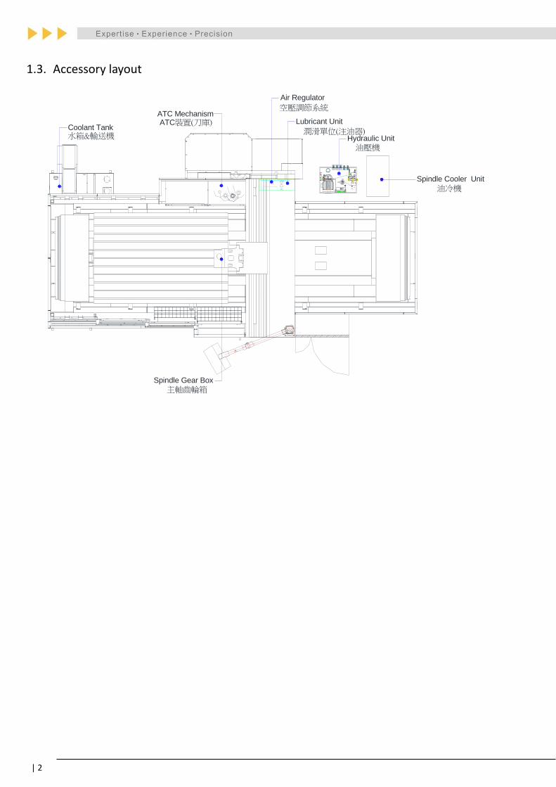
1.3. Accessory layout
VP5F
AW407-CA2
Coolant Tank
ATC Mechanism
Air Regulator
Lubricant Unit
Hydraulic Unit
Spindle Cooler Unit
Spindle Gear Box
ATC裝置(刀庫)潤滑單位(注油器)
油壓機
水箱&輸送機
主軸齒輪箱
油冷機
空壓調節系統

All specifications are subject to change without prior notice. 3 |
2. Machine Feature
The main structures of the machine castings including the Base, Table, Column, Crossbeam, Saddle and
Headstock are designed by 3D graphics, together with structure analysis software to obtain the optimum
way to deploy ribs inside the casting, increasing the rigidity as well as the durability of the machine.
Linear Guide ways
X/Y axes are high rigidity and high precision roller type linear guide way. Z axis is standard with very
rigid box way design. However, according to different machining requirement, there is optional
linear guide way in Z axis upon request. Combined with reliable construction to enhance stable
performance and to absorb the vibration, linear guide way can achieve a long service life with
highly accurate motion.
Machine Base
The inside structure of base adopted V-shape design to provide optimum support and to ensure the
loading capacity of the machine. With roller type linear guide enhances not only the swiftness of
the machine but also the accuracy performance during high speed cutting.
Working table
Box in box structure rib design strengthens the table loading capacity.
Cross beam
The best rectangle and step type design of the cross beam not only ensures the rigidity but also
reduces structural deformation, offering efficient heavy cutting performance and stable cutting
accuracy.
Columns
Super-sized column structure with cross-section 700x350mm for super supporting to the cross
beam, and make sure machine to be more rigid and stable.
Headstock
Box in box structure design with square type ribs inside which not only efficiently reduces the
weight of headstock but also enhances the swiftness of the machine, showing excellent machining
rigidity in addition.
Gearbox
One piece casting design and strong structure ensures machining
rigidity and accuracy.
2-step transmission design: low speed with higher torque for heavy
cutting, and high speed with perfect cutting performance.
With stable coolant system for spindle and gear system, Japan
made gear (HAMADA KOKI) provides high speed, low noise, low
friction and best performance.

| 4
Z axis balancing system
Twin hydraulic cylinders plus pressured nitrogen accumulator balancing
design doesn’t just save the energy and keep the temperature of the
hydraulic oil tank stable. It also enhances the response time and
accuracy of Z axis movement.
Three axes transmission
X-Axis: Gear Transmission with gear ratio 1: 2 enhances the axial movement response efficiently.
Y and Z-Axis: Direct type transmission ensures the accuracy of positioning and repeatability.
Three axis position feedback
Three axes position feedback is executed by absolute feedback systems. No need to return to the
zero point after rebooting. Even when abnormal operation or power failure occurs, the absolute
position shall be ensured.
Three axes with anti-collision design
With anti-collision design for three axes bearing support unit can ensure the
longer service life of ball screw and bearing.
User friendly interface
Moveable pendulum operation panel design provides wider
operation area which is very convenient for setting up the zero
point.
Safety protection
Multi-piece splash guards protect not only the operator, but
also prevent the chips and lubricants to pollute the
environment. Multi-pieces operation door design is very
convenient to load/unload work piece.

All specifications are subject to change without prior notice. 5 |
3. Machine Specification
Model Unit DX-2216 DX-2716 DX-3216 DX-4216
CNC controller 0iMD/10.4" 0iMD/10.4" 0iMD/10.4" 0iMD/10.4"
Travel
Main structure ---
X/Y-linear guide
way
Z-boxway
(Z-linear guide
way-opt.)
X/Y-linear guide way
Z-boxway
(Z-linear guide
way-opt.)
X/Y-linear guide way
Z-boxway
(Z-linear guide
way-opt.)
X/Y-linear guide way
Z-boxway
(Z-linear guide
way-opt.)
Headstock balancing system --- Hydraulic
(Nitrogen)
Hydraulic
(Nitrogen)
Hydraulic
(Nitrogen)
Hydraulic
(Nitrogen)
X axis mm 2,200 2,700 3,200 4,200
Y axis mm 1,600 1,600 1,600 1,600
Z axis mm 800 800 800 800
Distance from spindle nose
to table mm 150-950 150-950 150-950 150-950
Distance between two
column mm 1,700 1,700 1,700 1,700
Distance from spindle center
to Z guide way mm 375 375 375 375
Working table
Table Length mm 2,000 2,500 3,000 4,000
Table Width mm 1,400 1,400 1,400 1,400
Table Load kg 8,000 9,000 10,000 12,000
T- Slot (Width x Number x
Pitch) mm 22x7x180 22x7x180 22x7x180 22x7x180
Height of Table (table surface
to ground) mm 852 852 852 852
Spindle
Spindle Taper --- BT 50 BT 50 BT 50 BT 50
Spindle Speed rpm 4,500 4,500 4,500 4,500
Spindle Gear maker --- Hamada Koki Hamada Koki Hamada Koki Hamada Koki
Spindle driven type --- Gear drive
2-step
Gear drive
2-step
Gear drive
2-step
Gear drive
2-step
Spindle outside diameter mm 190 190 190 190
Spindle Bearing I.D. (inside) mm 100 (7020) 100 (7020) 100 (7020) 100 (7020)
Spindle motor power
(continuous) kW 18.5 18.5 18.5 18.5
Spindle motor power (rated) kW 22 22 22 22

| 6
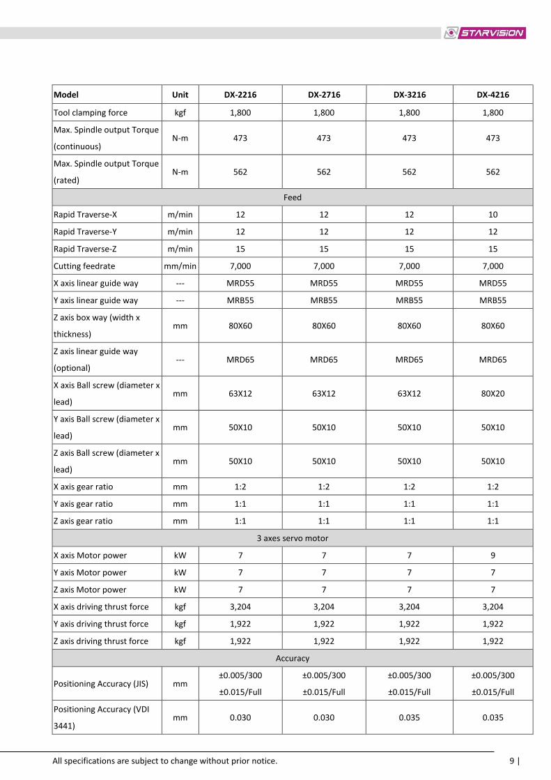
Model Unit DX-2216 DX-2716 DX-3216 DX-4216
Tool clamping force kgf 1,800 1,800 1,800 1,800
Max. Spindle output Torque
(continuous) N-m 473 473 473 473
Max. Spindle output Torque
(rated) N-m 562 562 562 562
Feed
Rapid Traverse-X m/min 12 12 12 10
Rapid Traverse-Y m/min 12 12 12 12
Rapid Traverse-Z m/min 15 15 15 15
Cutting feedrate mm/min 7,000 7,000 7,000 7,000
X axis linear guide way --- MRD55 MRD55 MRD55 MRD55
Y axis linear guide way --- MRB55 MRB55 MRB55 MRB55
Z axis box way (width x
thickness) mm 80X60 80X60 80X60 80X60
Z axis linear guide way
(optional) --- MRD65 MRD65 MRD65 MRD65
X axis Ball screw (diameter x
lead) mm 63X12 63X12 63X12 80X20
Y axis Ball screw (diameter x
lead) mm 50X10 50X10 50X10 50X10
Z axis Ball screw (diameter x
lead) mm 50X10 50X10 50X10 50X10
X axis gear ratio mm 1:2 1:2 1:2 1:2
Y axis gear ratio mm 1:1 1:1 1:1 1:1
Z axis gear ratio mm 1:1 1:1 1:1 1:1
3 axes servo motor
X axis Motor power kW 7 7 7 9
Y axis Motor power kW 7 7 7 7
Z axis Motor power kW 7 7 7 7
X axis driving thrust force kgf 3,204 3,204 3,204 3,204
Y axis driving thrust force kgf 1,922 1,922 1,922 1,922
Z axis driving thrust force kgf 1,922 1,922 1,922 1,922
Accuracy
Positioning Accuracy (JIS) mm ±0.005/300
±0.015/Full
±0.005/300
±0.015/Full
±0.005/300
±0.015/Full
±0.005/300
±0.015/Full
Positioning Accuracy (VDI
3441) mm 0.030 0.030 0.035 0.035

All specifications are subject to change without prior notice. 7 |
Model Unit DX-2216 DX-2716 DX-3216 DX-4216
Positioning Repeatability (JIS) mm ±0.003 ±0.003 ±0.003 ±0.003
Positioning Repeatability
(VDI 3441) mm 0.025 0.025 0.028 0.028
ATC
Magazine Type --- Hanging type Hanging type Hanging type Hanging type
ATC Type --- Arm type Arm type Arm type Arm type
Tool magazine capacity pcs 32 32 32 32
Max. tool size (full
pocket/next pockets empty) mm 125/245 125/245 125/245 125/245
Max. tool length mm 400 400 400 400
Max. tool weight kg 20 20 20 20
ATC time (Tool to tool)
(50Hz/60Hz) sec 5 5 5 5
ATC time (Chip to Chip) sec (24)20 (24)20 (24)20 (24)20
Tool selection method --- Random Random Random Random
Others
Coolant tank capacity liter 420 420 420 420
Max. coolant flow rate l/min 130 130 130 130
Coolant motor power W 2,380 2,380 2,380 2,380
Lubrication pump power W 17 17 17 17
Spindle chiller motor power W 373 373 373 373
Chip removal system --- Twin auger Twin auger Twin auger Twin auger
Ball screw lubrication --- Centralized Centralized Centralized Centralized
Guide ways lubrication --- Centralized Centralized Centralized Centralized
Lubrication Tank liter 8 8 8 8
Power required kVA 65 65 65 65
Dimension and Weight
Machine net weight kg 22,000 25,000 28,000 34,000
Machine gross weight kg 25,000 28,000 31,000 37,000
Floor space (Length) mm 7,600 8,600 9,600 11,600
Floor space (Width) mm 5,600 5,600 5,600 5,600
Floor space (Height) mm 4,700 4,700 4,700 4,700
Packing size (Length) mm 6,500 7,600 8,700 10,900
Packing size (Width) mm 3,700 3,700 3,700 3,700
Packing size (Height) mm 3,800 3,800 3,800 3,800

| 8
Model Unit DX-2220 DX-2720 DX-3220 DX-4220
CNC controller 0iMD/10.4" 0iMD/10.4" 0iMD/10.4" 0iMD/10.4"
Travel
Main structure ---
X/Y-linear guide way
Z-boxway
(Z-linear guide
way-opt.)
X/Y-linear guide way
Z-boxway
(Z-linear guide
way-opt.)
X/Y-linear guide way
Z-boxway
(Z-linear guide
way-opt.)
X/Y-linear guide way
Z-boxway
(Z-linear guide
way-opt.)
Headstock balancing system --- Hydraulic
(Nitrogen)
Hydraulic
(Nitrogen)
Hydraulic
(Nitrogen)
Hydraulic
(Nitrogen)
X axis mm 2,200 2,700 3,200 4,200
Y axis mm 2,000 2,000 2,000 2,000
Z axis mm 800 800 800 800
Distance from spindle nose
to table mm 150-950 150-950 150-950 150-950
Distance between two
column mm 2,100 2,100 2,100 2,100
Distance from spindle
center to Z guide way mm 375 375 375 375
Working table
Table Length mm 2,000 2,500 3,000 4,000
Table Width mm 1,700 1,700 1,700 1,700
Table Load kg 8,000 9,000 10,000 12,000
T- Slot (Width x Number x
Pitch) mm 22x9x180 22x7x180 22x7x180 22x7x180
Height of Table (table
surface to ground) mm 852 852 852 852
Spindle
Spindle Taper --- BT 50 BT 50 BT 50 BT 50
Spindle Speed rpm 4,500 4,500 4,500 4,500
Spindle Gear maker --- Hamada Koki Hamada Koki Hamada Koki Hamada Koki
Spindle driven type --- Gear drive
2-step
Gear drive
2-step
Gear drive
2-step
Gear drive
2-step
Spindle outside diameter mm 190 190 190 190
Spindle Bearing I.D. (inside) mm 100 (7020) 100 (7020) 100 (7020) 100 (7020)
Spindle motor power
(continuous) kW 18.5 18.5 18.5 18.5
Spindle motor power
(rated) kW 22 22 22 22
All specifications are subject to change without prior notice. 9 |
Model Unit DX-2216 DX-2716 DX-3216 DX-4216
Tool clamping force kgf 1,800 1,800 1,800 1,800
Max. Spindle output Torque
(continuous) N-m 473 473 473 473
Max. Spindle output Torque
(rated) N-m 562 562 562 562
Feed
Rapid Traverse-X m/min 12 12 12 10
Rapid Traverse-Y m/min 12 12 12 12
Rapid Traverse-Z m/min 15 15 15 15
Cutting feedrate mm/min 7,000 7,000 7,000 7,000
X axis linear guide way --- MRD55 MRD55 MRD55 MRD55
Y axis linear guide way --- MRB55 MRB55 MRB55 MRB55
Z axis box way (width x
thickness) mm 80X60 80X60 80X60 80X60
Z axis linear guide way
(optional) --- MRD65 MRD65 MRD65 MRD65
X axis Ball screw (diameter x
lead) mm 63X12 63X12 63X12 80X20
Y axis Ball screw (diameter x
lead) mm 50X10 50X10 50X10 50X10
Z axis Ball screw (diameter x
lead) mm 50X10 50X10 50X10 50X10
X axis gear ratio mm 1:2 1:2 1:2 1:2
Y axis gear ratio mm 1:1 1:1 1:1 1:1
Z axis gear ratio mm 1:1 1:1 1:1 1:1
3 axes servo motor
X axis Motor power kW 7 7 7 9
Y axis Motor power kW 7 7 7 7
Z axis Motor power kW 7 7 7 7
X axis driving thrust force kgf 3,204 3,204 3,204 3,204
Y axis driving thrust force kgf 1,922 1,922 1,922 1,922
Z axis driving thrust force kgf 1,922 1,922 1,922 1,922
Accuracy
Positioning Accuracy (JIS) mm ±0.005/300
±0.015/Full
±0.005/300
±0.015/Full
±0.005/300
±0.015/Full
±0.005/300
±0.015/Full
Positioning Accuracy (VDI
3441) mm 0.030 0.030 0.035 0.035

| 10
Model Unit DX-2216 DX-2716 DX-3216 DX-4216
Positioning Repeatability
(JIS) mm ±0.003 ±0.003 ±0.003 ±0.003
Positioning Repeatability
(VDI 3441) mm 0.025 0.025 0.028 0.028
ATC
Magazine Type --- Hanging type Hanging type Hanging type Hanging type
ATC Type --- Arm type Arm type Arm type Arm type
Tool magazine capacity pcs 32 32 32 32
Max. tool size (full
pocket/next pockets empty) mm 125/245 125/245 125/245 125/245
Max. tool length mm 400 400 400 400
Max. tool weight kg 20 20 20 20
ATC time (Tool to tool)
(50Hz/60Hz) sec 5 5 5 5
ATC time (Chip to Chip) sec (24)20 (24)20 (24)20 (24)20
Tool selection method --- Random Random Random Random
Others
Coolant tank capacity liter 490 490 490 490
Max. coolant flow rate l/min 130 130 130 130
Coolant motor power W 2,380 2,380 2,380 2,380
Lubrication pump power W 17 17 17 17
Spindle chiller motor power W 373 373 373 373
Chip removal system --- Twin auger Twin auger Twin auger Twin auger
Ball screw lubrication --- Centralized Centralized Centralized Centralized
Guide ways lubrication --- Centralized Centralized Centralized Centralized
Lubrication Tank liter 8 8 8 8
Power required kVA 65 65 65 65
Dimension and Weight
Machine net weight kg 23,000 26,000 29,000 35,000
Machine gross weight kg 26,000 29,000 32,000 38,000
Floor space (Length) mm 7,600 8,600 9,600 11,600
Floor space (Width) mm 6,100 6,100 6,100 6,100
Floor space (Height) mm 4,700 4,700 4,700 4,700
Packing size (Length) mm 6,500 7,600 8,700 10,900
Packing size (Width) mm 4,100 4,100 4,100 4,100
Packing size (Height) mm 3,800 3,800 3,800 3,800

All specifications are subject to change without prior notice. 11 |
4. Standard Accessories
Item Standard Accessories
1 FANUC 0i-MD controller
2 18.5/22 kW spindle motor
3 4,500rpm 2-step gear drive spindle
4 X/Y axes linear guide way and Z axis box way
5 Z travel 800mm
6 Automatic Tool Changer 32 tools
7 Fully enclosed splash guard (roof excluded)
8 X/Y/Z axes absolute pulse coder
9 Rigid tapping
10 Twin hydraulic cylinders
11 Nitrogen balancing system
12 Automatic lubrication system
13 Spindle oil cooler
14 Air blast through spindle
15 Manual Pulse Generator
16 Working lamp
17 3-color alarm lamp
18 RS-232 interface
19 Heat exchanger for electrical cabinet
20 Water gun and air gun interface
21 Cutting coolant system
22 Twin auger chip removal system
23 Belt type chip conveyor with cart
24 Leveling bolts & blocks
25 Tool box
26 Operation manual and electric drawing
27 Two years warranty for CNC controller system
28 One year warranty for mechanical parts
| 12
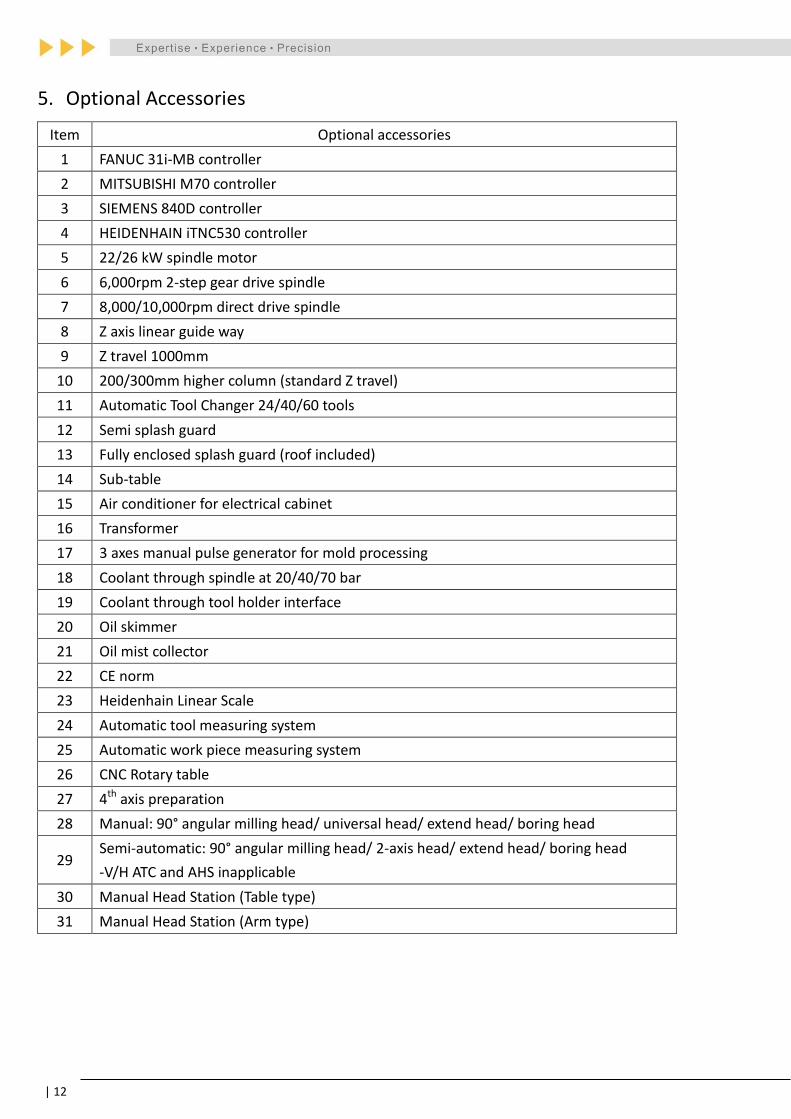
5. Optional Accessories
Item Optional accessories
1 FANUC 31i-MB controller
2 MITSUBISHI M70 controller
3 SIEMENS 840D controller
4 HEIDENHAIN iTNC530 controller
5 22/26 kW spindle motor
6 6,000rpm 2-step gear drive spindle
7 8,000/10,000rpm direct drive spindle
8 Z axis linear guide way
9 Z travel 1000mm
10 200/300mm higher column (standard Z travel)
11 Automatic Tool Changer 24/40/60 tools
12 Semi splash guard
13 Fully enclosed splash guard (roof included)
14 Sub-table
15 Air conditioner for electrical cabinet
16 Transformer
17 3 axes manual pulse generator for mold processing
18 Coolant through spindle at 20/40/70 bar
19 Coolant through tool holder interface
20 Oil skimmer
21 Oil mist collector
22 CE norm
23 Heidenhain Linear Scale
24 Automatic tool measuring system
25 Automatic work piece measuring system
26 CNC Rotary table
27 4th axis preparation
28 Manual: 90° angular milling head/ universal head/ extend head/ boring head
29 Semi-automatic: 90° angular milling head/ 2-axis head/ extend head/ boring head
-V/H ATC and AHS inapplicable
30 Manual Head Station (Table type)
31 Manual Head Station (Arm type)

All specifications are subject to change without prior notice. 13 |
6. Major Technical Data
6.1. Guide way type and dimension
X axis guide way type and dimension (Linear guide way)
(unit: mm)

| 14
Y axis guide way type and dimension (Linear guide way)
(unit: mm)

All specifications are subject to change without prior notice. 15 |
Z axis guide way type and dimension (Box way – Standard)
HRC50
Z axis guide way type and dimension (Linear guide way - Optional)
(unit: mm)

| 16
6.2. Table dimension and T-slot specification
(-1
)
(unit: mm)
Model A B C D E F G H I
DX-2216 2,000 1,400 160 180 7 22H8 38 16 38
DX-2716 2,500 1,400 160 180 7 22H8 38 16 38
DX-3216 3,000 1,400 160 180 7 22H8 38 16 38
DX-4216 4,000 1,400 160 180 7 22H8 38 16 38
DX-2220 2,000 1,700 130 180 9 22H8 38 16 38
DX-2720 2,500 1,700 130 180 9 22H8 38 16 38
DX-3220 3,000 1,700 130 180 9 22H8 38 16 38
DX-4220 4,000 1,700 130 180 9 22H8 38 16 38

All specifications are subject to change without prior notice. 17 |
6.3. Working Travel
X+ X-
Z-
Z+
Y+ Y-

| 18
X AXIS
Z A
XIS
A
Y AXIS
CD
B
DX Series Working Travel (unit: mm)
DX-2216 DX-2716 DX-3216 DX-4216 DX-2220 DX-2720 DX-3220 DX-4220
A 2,200 2,700 3,200 4,200 2,200 2,700 3,200 4,200
B 1,600 1,600 1,600 1,600 2,000 2,000 2,000 2,000
C 800 800 800 800 800 800 800 800
D 150 150 150 150 150 150 150 150

All specifications are subject to change without prior notice. 19 |
6.4. Machine Floor Plan
F
5,6
00
5,6
00
5,6
00
5,6
00
5,9
00
5,9
00
5,9
00
5,9
00
E
8,7
00
9,7
00
10
,70
0
12
,70
0
8,7
00
9,7
00
10
,70
0
12
,70
0
D
77
C
4,2
00
│
3,4
00
B
4,6
00
4,6
00
4,6
00
4,6
00
4,9
00
4,9
00
4,9
00
4,9
00
A
7,6
00
8,6
00
9,6
00
11
,60
0
7,6
00
8,6
00
9,6
00
11
,60
0
Mo
del
DX
-22
16
DX
-27
16
DX
-32
16
DX
-42
16
DX
-22
20
DX
-27
20
DX
-32
20
DX
-42
20

| 20
6.5. Spindle Power and Torque Chart
Type I: One piece gear head with two step gear transmission (Standard)
30min.
Continuous18.5
22
Torque(Nm)Output(kW) Torque(Nm)
100
200
300
500
600
400383
050
3741000
13422000 3000 4000 5000 6000
Spindle Speed(rpm)
2429
132157
562
473
22KW
30min.
18.5KW
Continuous
L/H
SPINDLE MOTOR TORQUE CHART
2-STEP GEAR TYPE SPINDLEMOTOR: FANUCα 18

All specifications are subject to change without prior notice. 21 |
Type I: One piece gear head with two step gear transmission (Optional)
30min.
Continuous22
26
100
200
300
400383
500
600
562
700
665
Torque(Nm)Output(kW)
30min.
Continuous
26kW
22kW
Torque(Nm)
185157
3529
050
3741000
13422000 3000 4000 5000 6000
Spindle Speed(rpm)
L/H
SPINDLE MOTOR TORQUE CHART
2-STEP GEAR TYPE SPINDLEMOTOR: FANUCα 22

| 22
Type II Direct Drive Spindle Motor α18 (Optional)
2000 4000 6000 8000 100000
50
100
150
200
250
1500
22kW
18.5kW
30kW
Torque(Nm)Output(kW)
10
20
30
40
22
26
35
Spindle Speed(rpm)
L/H
15min.
30min.
Continuous
15min.
30min.
Continuous
28.72117.7
Torque(Nm)
SPINDLE MOTOR TORQUE CHART
DIRECT DRIVE SPINDLEMOTOR: FANUCα 18

All specifications are subject to change without prior notice. 23 |
Type II Direct Drive Spindle Motor α22 (Optional)
2000 4000 6000 8000 100000
50
100
150
200
250
1500
22kW
26kW
35kW
Torque(Nm)Output(kW)
10
20
30
40
22
26
35
Spindle Speed(rpm)
L/H
15min.
30min.
Continuous
15min.
30min.
Continuous
Torque(Nm)
33.424.821
SPINDLE MOTOR TORQUE CHART
DIRECT DRIVE SPINDLEMOTOR: FANUCα 22

| 24
6.7. Tool Shank and Pull Stud Dimension
Type I: BT-50/CAT50

All specifications are subject to change without prior notice. 25 |
Type II: DIN-50/ (DIN69872B-50)

| 26
7. Components Specification
Component suppliers in the same quality level are subject to change to
meet strict delivery schedule.
7.1. Spindle
A. Spindle Type and Specification
Driven
Way
Speed
(rpm)
Spindle
Taper
Spindle Nose End Bearing inside
and outside
diameter
Rear side of
spindle Brand Description
Gear
Type
4,500 #50
NSK 7020* 5 SET 100x150mm 6016x1pce
6,000 NTN 7020* 5 SET
Direct
Drive 10,000
#40 FAG 7014*4 SET 70x110mm n/a
#50 FAG 7018C*4 SET 90x140mm
B. Spindle Gear Specification
Gear Accuracy Lubrication Way Coolant Way
JIS 0 Oil Bath Oil Coolant

All specifications are subject to change without prior notice. 27 |
7.2. Feeding Axis
A. Bearing Specification
Axis Model Motor End Brand Free End Brand
X Axis
DX-2216/20
40TAC72BPN7B*4 SET
NSK
FAG
40TAC72BPN7B*4 SET
NSK
FAG
DX-2716/20
DX-3216/20
DX-4216/20 60TAC120BPN7B*4 SET 60TAC120BPN7B*4 SET
Y Axis DX Series 40TAC72BPN7B*4 SET 40TAC72BPN7B*4 SET
Z Axis DX Series 40TAC72BPN7B*4 SET 40TAC72BPN7B*3 SET
B. Ball Screw Specification of Feeding Axis
Feeding Axis Diameter x Lead
(Unit: mm)
Nut
Specification Grade Lubrication way
X Axis
DX-2216/20
Φ63 x 12 FDV
C3 Oil Lubrication
DX-2716/20
DX-3216/20
DX-4216/20 Φ80 x 20
Y Axis DX Series Φ50 x 10 FDV
Z Axis DX Series Φ50 x 10 FDV
Remarks Nut Specification: FDV (External Ball/P.B&S.L); FDW(Internal Ball/P.L&S.H)

| 28
7.3. Linear guide way
Feeding Axis Rail Carriage
Specification Width Height Quantity Width
X Axis
DX-2216/20
R55 53mm 48mm
6
100mm DX-2716/20 8
DX-3216/20 8
DX-4216/20 10
Y Axis DX Series R55 53mm 48mm 5 140mm
Z Axis DX Series R65 63mm 58mm 6 126mm

All specifications are subject to change without prior notice. 29 |
7.4. Main Supplier
Component Manufacturer Country of origin
Casting YCFI/Fuyu Taiwan
Linear guide SCHNEERBERGER/Hiwin Germany/Taiwan
Spindle bearing FAG/NSK/NTN Germany/Japan
Spindle gear HAMADA Japan
Spindle oil cooler Wexten/Habor/Kaukan Taiwan
X axis ball screw Hiwin/PMI/SHUTON Taiwan/Spain
Y axis ball screw Hiwin/PMI/SHUTON Taiwan/Spain
Z axis ball screw Hiwin/PMI/SHUTON Taiwan/Spain
Tool magazine Gifu Taiwan
X/Y/Z axis linear scale HEIDENHAIN Germany
Accumulator HYDAC Germany
Automatic oil lubrication system Chen Yeng/SHOWA Taiwan/Japan
Hydraulic pump ANSON Taiwan
Solenoid valve (hydraulic system) DOFLUID Taiwan
Solenoid Valve (pneumatic system) PAKER USA
Pneumatic actuator UNIMEC Taiwan
Coolant pump WALRUS Taiwan
Coolant valve DOFLUID Taiwan
Transformer SUENN LIANG/Shin Hsing Taiwan
Magnetic contactor SIEMENS Germany
Thermal relay SIEMENS Germany
Molded-case circuit breaker SIEMENS Germany
Terminal blocks SIEMENS Germany
PCB RELAY SIEMENS Germany
Heat exchanger Habor Taiwan
Metal-oxide varistor FOTEK Taiwan
Quick Connector MS Taiwan
Band Switch FUTURE Taiwan
Cable carrier igus Germany
Controller panel suspension BERNSTEIN Germany
Warning Light / Work Light EMINENT MAIN Taiwan
Hand pulse generator TOSUKU Japan
HONDA connector HONDA Japan
Limit switch EUCHNET Germany
Proximity Switch ILTC Italy
Milling Head YIH KUAN/Gong Yang Taiwan

| 30
8. Optional accessories
8.1. Coolant through Spindle
8.2. Oil Skimmer
2
4
3
1
SpecificationItem Parts Name Q'ty
Oil Skimmer1
2 Cover
Filter3
4 Tank
1
1
1
1
400mm (left)

All specifications are subject to change without prior notice. 31 |
8.3. Automatic Tool Measuring System

| 32
8.4. Automatic Workpiece Measuring System

All specifications are subject to change without prior notice. 33 |
9. Accuracy report
1. Geometric Accuracy Inspection Unit: mm
No. Item Method Illustration Tolerance Measured
result
1 Straightness
of table
(X-axis)
XZ
plane
Move the table to the middle of X-axis stroke.
Move the spindle head to the middle of Y-axis stroke.
Place a level gauge on the center of table. Reset the level gauge.
Move the table (along X-axial direction) to measure the straightness at three positions, center and both edges, at least.
The maximal difference obtained is the measured result.
1000-2000 0.05
2000-3000 0.06
3000↑ 0.07
YZ
plane
2 Squareness
between
linear
movement XZ
plane
Move the table to the middle of X-axis stroke.
Move the spindle head to the middle of Y-axis stroke.
Place a square gauge parallel to X-axial direction on the table
Fix a dial gauge on the spindle head and let its stylus touch the square gauge.
Reset the dial gauge. Move spindle head along Z-axial direction
and observe the variation of it. The maximal difference obtained is the
measured result.
0.02/400
YZ
plane
Move the table to the center of X-axis travel.
Move the spindle head to the center o Y-axis travel.
Place a square gauge parallel to Y-axial direction on the table
Fix a dial gauge on the spindle head and let its stylus touch the square gauge.
Reset the dial gauge. Move spindle head along Z-axial direction
and observe the variation of it. The maximal difference obtained is the
measured result.
0.02/400
XY
plane
Move the table to the middle of X-axis stroke.
Move the spindle head to the middle of Y-axis stroke.
Place a square gauge parallel to X-axial direction on the table.
Fix a dial gauge on the spindle head and let its stylus touch the square gauge.
Reset the dial gauge. Move spindle head along Y-axial direction
and observe the variation of it. The maximal difference obtained is the
measured result.
0.015/400

| 34
Unit: mm
No. Item Method Illustration Tolerance Measured
result
3 Parallelism between
table and axis motion.
Fix a dial gauge on the spindle head, and let its stylus touch the table surface.
Reset this dial gauge. Move spindle head along Y-axial direction,
and observe the variation of it. The maximal difference obtained is the
measured result. Y
1000-2000 0.04
2000-3000 0.05
3000↑ 0.06
4 Parallelism between the spindle and the
X-axis motion.
Fix a dial gauge on the spindle head, and let its stylus touch the table surface.
Reset this dial gauge. Move the table along X-axial direction, and
observe the variation of it. The maximal difference obtained is the
measured result.
X
5
Parallelism between table movement along
X-axis motion and T-slot side of the table.
Fix a dial gauge on the spindle head, and let its stylus touch the side of T-slot on the table.
Move the table. The maximal difference obtained is the
measured result.
1000-2000 0.04
2000-3000 0.05
3000↑ 0.06
6 The run-out of internal
taper of the spindle
Fix a test bar in the taper on the spindle. Place a dial gauge at the nearest position of
spindle, and place and other dial gauge at a 300mm distance from the first position.
Reset this dial gauge. Rotate the spindle and observe the
variation of the gauge. The maximal difference obtained is the
measured result.
A: 0.005
B: 0.02
7 Perpendicularity between spindle and table surface.
Move the table to the middle of X-axial stroke and Y-axial travel. Fix a dial gauge on the spindle head, and let its stylus touch the table surface.
Rotate the spindle and observe the variation of the gauge.
The maximal difference obtained is the measured result.
XZ
Plane 0.02/400
YZ
plane 0.02/400
8 Run-out of the spindle
nose
Place a stylus dial gauge to touch the surface of the outside edge of the spindle.
Rotate the spindle and observe the variation of the gauge. The maximal difference obtained is the measured result.。
0.01
9 Run-out of the spindle face
Place a stylus of dial gauge to touch the surface of the spindle end.
Rotate the spindle and observe the variation of the gauge. The maximal difference obtained is the measured result.
0.01
A. the nearest position
B. 300mm away A position

All specifications are subject to change without prior notice. 35 |
2. Positioning Accuracy Inspection Unit: mm
No. Item Method Illustration Tolerance Measured
result
1 Positioning
accuracy
inspection
Move the machine (spindle or table) to positive (negative) position and then stop it.
Take this position as the norm, move the spindle to the same direction at 50% of the highest feedrate and then measure the accuracy.
According to the table below, select specified measuring intervals and measure the difference between the actual moving distance from the norm position and the specified moving distance.
Calculate the maximal difference within the normal distance.
Based on the method, the maximal difference obtained is the measured result. Then, do this measurement in X, Y, and Z axial directions respectively.
Motion range Measured distance
Normal distance
Less than 1000
50 300
Above 1000 100
±0.015/Full stroke
X
Y
Z
Do this measure to three axes at 50% of the highest federate. There should be 6 points on every meter to measure at least. Do this measurement five times continuously.
Analyze the obtained values statistically.
Please refer to P values
list for DX series in
Table 1.
X
Y
Z
Table 1: P values list for DX series
Model P value(VDI 3441)(mm) Model P value(VDI 3441)(mm)
DX-2216 0.03 DX-3216 0.035
DX-2220 0.03 DX-3220 0.035
DX-2716 0.03 DX-4216 0.035
DX-2720 0.03 DX-4220 0.035

| 36
3. Repeatability Accuracy Inspection Unit: mm
NO. Item Method Illustration Tolerance Measured
result
1 Repeatability
accuracy
At least, Select three points (at the middle, and two ends) as normal points.
Move the spindle at 50% of the highest federate under the same setting conditions (direction). Do positioning accuracy inspections 7 times.
Find the obtained maximal differences. Divide the maximal obtained value. It is
the measured result.
±0.003
X
Y
Z
The same as positioning accuracy test.
Please refer to Ps
values list for DX
series in Table 2.
X
Y
Z
Table 2: Ps values list for DX series
Model Ps value (VDI 3441) (mm) Model Ps value (VDI 3441) (mm)
DX-2216 0.025 DX-3216 0.028
DX-2220 0.025 DX-3220 0.028
DX-2716 0.025 DX-4216 0.028
DX-2720 0.025 DX-4220 0.028
4. Circularity Inspection Unit: mm
NO. Item Method Illustration Tolerance Measured
result
1 Circularity inspection
Place the double bar (DDB) test device on the center of the table.
At 2000 mm/min feedrate speed and with 150mm radius, do this measurement when spindle rotates a circle CW and CCW respectively.
The difference between the maximal measured diameter and the minimal measured diameter is the measured result.
0.03/
300
XY
Plane
Y
X

All specifications are subject to change without prior notice. 37 |
10. Shipping requirement
Model Dimension (mm) Gross
weight
(tons)
Container
type Length Width Height
DX-2216 6700 3650 3800 25 1x40’ FR
DX-2716 8000 3650 3800 26.5 1x40’ FR
DX-3216 8700 3650 3800 27 1x40’ FR
DX-4216 10700 3650 3800 29 1x40’ FR
DX-2220 6700 4200 3800 26 1x40’ FR
DX-2720 8000 4200 3800 27.5 1x40’ FR
DX-3220 8700 4200 3800 28 1x40’ FR
DX-4220 10700 4200 3800 30 1x40’ FR

| 38
11. Foundation Plan
11.1. J Bolt
Unit: mm
J bolt components introduction
A Machine base
B J Bolt
C M16 nut
D M16 pad
E M32 nut
F Leveling screw
G Leveling block (small)
H Leveling block (big)
I C-ring

All specifications are subject to change without prior notice. 39 |
11.2. H Beam
Unit: mm
H Beam components
A Machine Base
B M16 Bolt
C M16 Nut
D M16 Pad
E M36 Nut
F Leveling screw
G Leveling block (small)
H Leveling block (big)
I H Beam