Guide to Prop Balancing€¦ · balancing will only improve the vibration caused by mass unbalance...
23
ACES Systems Guide to Propeller Balancing Aviation Division 10737 Lexington Drive Knoxville, TN 37923-3294 (865) 966-5856 Phone (865) 675-1241 Fax 1000-OM-01 Revision 2.0 June 1996
Transcript of Guide to Prop Balancing€¦ · balancing will only improve the vibration caused by mass unbalance...
ACES SystemsGuide to
Propeller Balancing
Aviation Division
10737 Lexington DriveKnoxville, TN 37923-3294
(865) 966-5856 Phone(865) 675-1241 Fax
1000-OM-01
Revision 2.0June 1996
II
FAA Approval
III
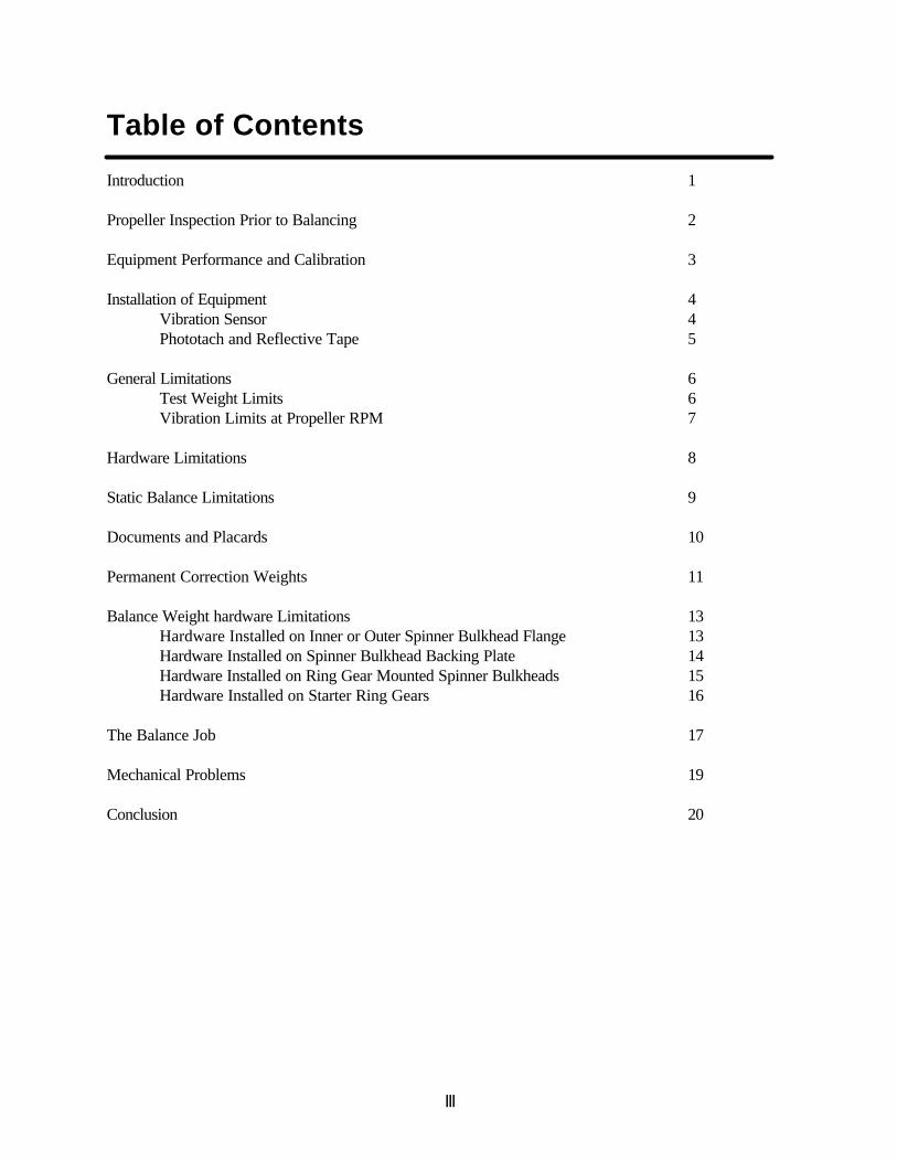
Table of Contents
Introduction 1
Propeller Inspection Prior to Balancing 2
Equipment Performance and Calibration 3
Installation of Equipment 4Vibration Sensor 4Phototach and Reflective Tape 5
General Limitations 6Test Weight Limits 6Vibration Limits at Propeller RPM 7
Hardware Limitations 8
Static Balance Limitations 9
Documents and Placards 10
Permanent Correction Weights 11
Balance Weight hardware Limitations 13Hardware Installed on Inner or Outer Spinner Bulkhead Flange 13Hardware Installed on Spinner Bulkhead Backing Plate 14Hardware Installed on Ring Gear Mounted Spinner Bulkheads 15Hardware Installed on Starter Ring Gears 16
The Balance Job 17
Mechanical Problems 19
Conclusion 20
1
Introduction
The dynamic components in aircraft engines and propeller systems are manufactured to very strict limits,but even when these limits are adhered to, unbalance errors can occur. These errors result from a “stackup” of small unbalances in the engine power train and propeller system that is installed in the aircraft.When undesirable vibration is detected, some of the components of the propulsion system, notably thepropeller and spinner assembly can be spin trim balanced to improve the running vibration levels of theentire system.
Balancing the propulsion assembly can provide substantial reductions in transmitted vibration and noise tothe cabin and also reduces excessive damage to other aircraft and engine components.
Remember that propeller smoothing is not a “cure all” for every vibration you feel in the aircraft. Spin trimbalancing will only improve the vibration caused by mass unbalance of the externally rotating componentsof the propulsion system. Balancing will not improve the vibration if the engine or aircraft is in poormechanical condition. Defective, worn, or loose parts, will make balancing impossible.All dynamic balancing equipment operates fundamentally the same. Each must provide:
1. A means of measuring the vibration level.
2. A means of measuring the angular reference of the vibration.
3. A means of determining the trim weight adjustments necessary to reduce the vibration of thepropulsion system.
The method used to accomplish each task is the primary difference between one manufacturer'sequipment and another.
The advent of balancing computers like the ACES ProBalancer has revolutionized propeller spin balancingby making the job of measuring vibration and calculating balance weight location an easy task.The basic procedure is:
1. Run the engine in “as is condition” to find out the existing vibration level.
2. Attach a known mass trim weight at a known location on the spinner.
3. Run the engine a second time to measure the reaction of the propeller to the weigh.
4. Calculate a solution based on the first three pieces of information.
This booklet focuses on procedures and practices for doing a balance job. Included are instructions oninstalling vibration sensors, photo tachometers and reflective tape; as well as, selecting the proper masstrim weights, attaching trial weights, attaching permanent weights and other hints for simplifying yourbalance job.
This manual does not provide details on using your balancing equipment. Please review the equipmentmanual included with your balancer for detailed information on its operation.

2
Propeller Inspection Prior to Balancing
1. Insure all Airworthiness Directives have been complied with for the propeller you are going tobalance.
2. Determine if there is a balancing procedure published by the airframe, engine or propellermanufacturer; if there is, it will take precedence.
3. Inspect the propeller blades for damage, nicks etc. refer to FAA Advisory Circular 20-37Dwhich outlines care of metal propellers, and to applicable propeller manufacturersmaintenance requirements.
4. If balancing composite propeller blades, refer to the propeller manufacturer's procedures forrepair of the propeller.
5 Inspect propeller assembly for proper installation and security.
WARNING
Performa a visual inspection of the spinner and spinner bulkhead for cracks, stop drills andwelding. Mass trim weights MUST NOT be attached to a part with any of these conditions.
6. To prevent an excessive number of weights from being attached to the spinner, remove anymass trim weights attached from previous balance jobs.
WARNING
Static balance weight attached to the propeller hub by a certified propeller shop MUSTNOT be removed.
3
Equipment Performance and CalibrationIt is vital that the equipment used to perform the balance check meet certain standards of conformanceand accuracy.
Attest that the balance equipment has a valid calibration certificate traceable to the NIST NationalInstitute of Standards and Tests (formally the NBS). The equipment calibration is to be performed on therecommended schedule of the equipment manufacturer.
4
Installation of Equipment
Vibration Sensor
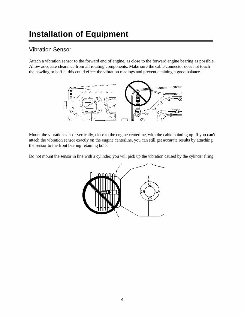
Attach a vibration sensor to the forward end of engine, as close to the forward engine bearing as possible.Allow adequate clearance from all rotating components. Make sure the cable connector does not touchthe cowling or baffle; this could effect the vibration readings and prevent attaining a good balance.
Mount the vibration sensor vertically, close to the engine centerline, with the cable pointing up. If you can'tattach the vibration sensor exactly on the engine centerline, you can still get accurate results by attachingthe sensor to the front bearing retaining bolts.
Do not mount the sensor in line with a cylinder; you will pick up the vibration caused by the cylinder firing.
5
Determine the vibration sensor location in this order:
1. Forward part of the engine, vertically, on top of the engine centerline, cable up.
2. Forward part of the engine, vertically, to the side of the engine centerline, cable up.
3. Forward part of the engine, vertically, below the engine centerline, cable down.
4. Forward part of the engine, sensor stud pointing toward centerline of engine, cable away fromengine.
Phototach and Reflective Tape
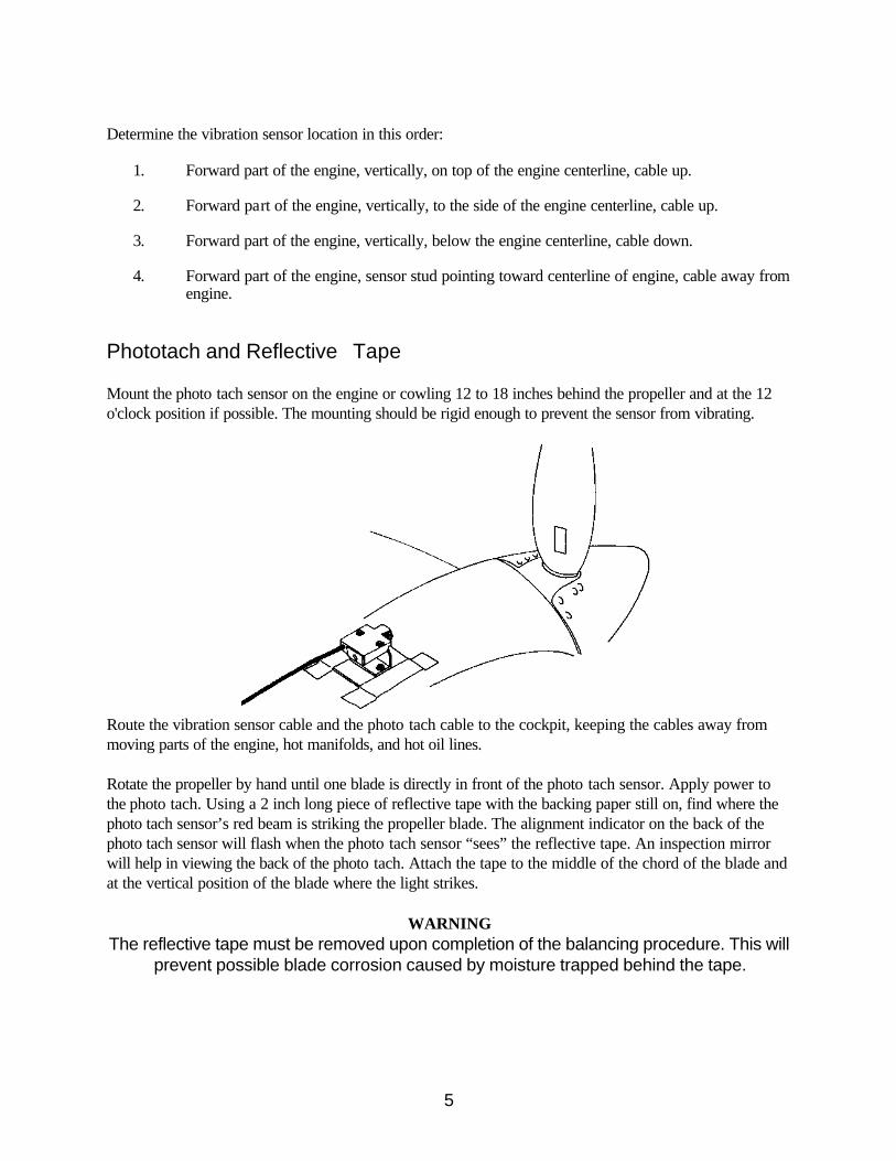
Mount the photo tach sensor on the engine or cowling 12 to 18 inches behind the propeller and at the 12o'clock position if possible. The mounting should be rigid enough to prevent the sensor from vibrating.
Route the vibration sensor cable and the photo tach cable to the cockpit, keeping the cables away frommoving parts of the engine, hot manifolds, and hot oil lines.
Rotate the propeller by hand until one blade is directly in front of the photo tach sensor. Apply power tothe photo tach. Using a 2 inch long piece of reflective tape with the backing paper still on, find where thephoto tach sensor’s red beam is striking the propeller blade. The alignment indicator on the back of thephoto tach sensor will flash when the photo tach sensor “sees” the reflective tape. An inspection mirrorwill help in viewing the back of the photo tach. Attach the tape to the middle of the chord of the blade andat the vertical position of the blade where the light strikes.
WARNINGThe reflective tape must be removed upon completion of the balancing procedure. This will
prevent possible blade corrosion caused by moisture trapped behind the tape.
6
General Limitations
WARNING
Do not exceed flight manual or engine manual limits
NOTE
Pay particular attention to cylinder head temperatures on piston engines.
CAUTION
Unless otherwise specified by the airframe, engine or propeller manufacturer, vibration levelsmust not exceed 1.20 inches per second (IPS) peak at the propeller speed. If this value is
exceeded the propeller must be removed and static balanced by an approved propeller shopbefore attempting dynamic balancing.
CAUTION
The maximum amount of weight is 30 Grams on any one screw.
CAUTION
Minimum screw size for a test weight attachment is #10 (10-32). The screw length shall be longenough to provide at least three full threads showing through the retaining nut plate on the
spinner bulkhead.
WARNING
Weights added to the spinner retaining screws are prohibited from use as a permanentinstallation.
Test Weight Limits
The estimated weight should be large enough to effect a change in the propeller vibration but small enoughnot to cause damage if placed in an incorrect position.
If you are using a system that does not compute the trial weight, the formula is:
Test Weight = ((Engine Horsepower/10)+30) x IPS
WARNING
All weights and screws attached to the spinner or spinner bulkhead must clear the stationaryportions of the cowling and engine by at least 0.25 inches.
CAUTION
Adhesive backed weights are not acceptable unless approved by an airframe, engine orpropeller manufacturer for that installation.

7
WARNING
Installation of balance washers to the outside of the spinner is not permitted as a permanentinstallation.
NOTE
FAA Engineering approval is required for installation criteria outside the guidelines of thispublication.
Vibration Limits At Propeller RPM
DANGER —-------------- 1.25 Inches Per Second (IPS) Peak Amplitude. The propeller should beremoved and a static balance performed.
VERY ROUGH —------- 1.00 Inches Per Second (IPS) Peak Amplitude. Propeller can be dynamicallybalanced; however a large amount of weight will be required. A propellerstatic balance is recommended. Operation at this vibration level could causedamage.
ROUGH ----------------- 0.50 Inches Per Second (IPS) Peak Amplitude. Propeller definitely requiresdynamic balance. Long term operation at this vibration level could causeexcessive wear.
SLIGHTLY ROUGH -- 0.25 Inches Per Second (IPS) Peak Amplitude. Dynamic balance willimprove passenger comfort.
FAIR----------------------- 0.15 Inches Per Second (IPS) Peak Amplitude. This is the maximumacceptable vibration level after dynamic balancing.
GOOD -------------------- 0.07 Inches Per Second (IPS) Peak Amplitude. Vibration levels below0.07 will not be detectable by pilots or passengers.
8
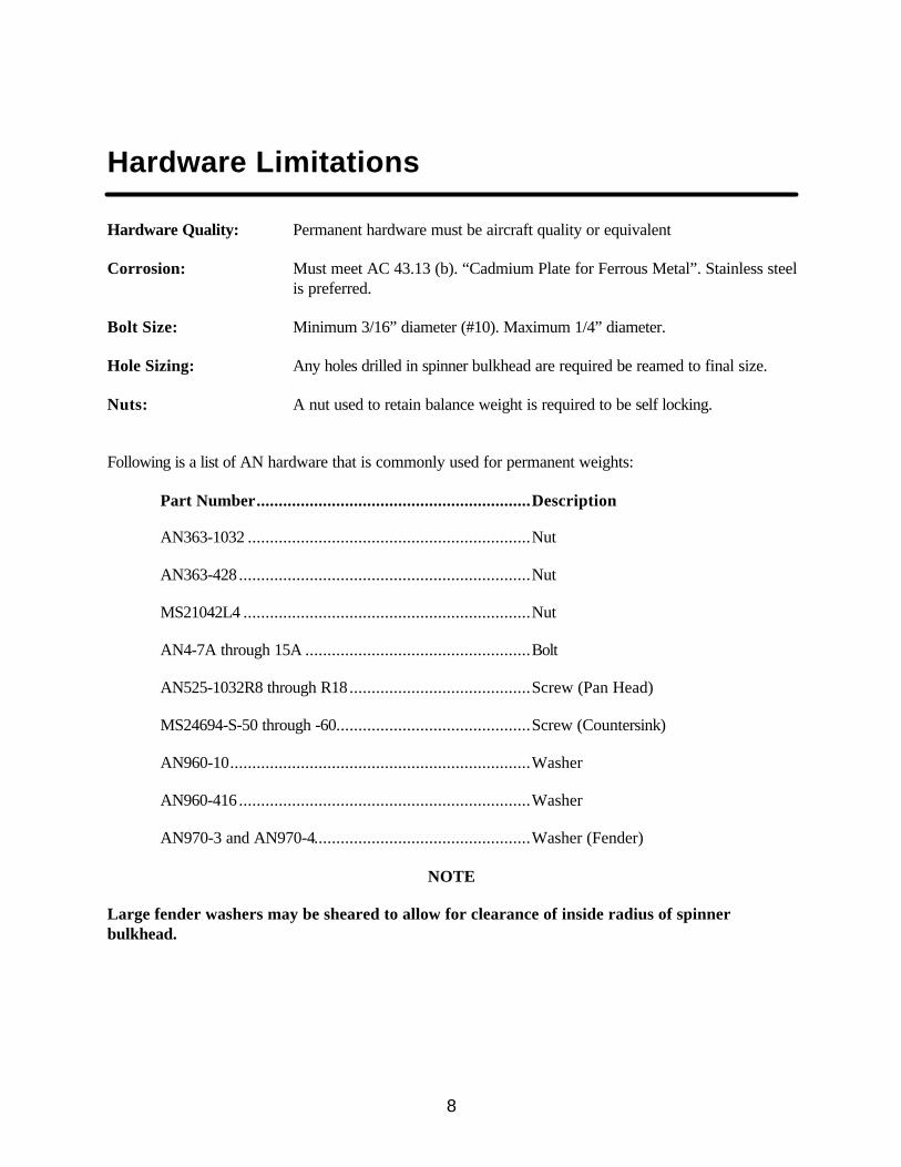
Hardware Limitations
Hardware Quality: Permanent hardware must be aircraft quality or equivalent
Corrosion: Must meet AC 43.13 (b). “Cadmium Plate for Ferrous Metal”. Stainless steelis preferred.
Bolt Size: Minimum 3/16” diameter (#10). Maximum 1/4” diameter.
Hole Sizing: Any holes drilled in spinner bulkhead are required be reamed to final size.
Nuts: A nut used to retain balance weight is required to be self locking.
Following is a list of AN hardware that is commonly used for permanent weights:
Part Number..............................................................Description
AN363-1032 ................................................................Nut
AN363-428 ..................................................................Nut
MS21042L4 .................................................................Nut
AN4-7A through 15A ...................................................Bolt
AN525-1032R8 through R18.........................................Screw (Pan Head)
MS24694-S-50 through -60............................................Screw (Countersink)
AN960-10....................................................................Washer
AN960-416 ..................................................................Washer
AN970-3 and AN970-4.................................................Washer (Fender)
NOTE
Large fender washers may be sheared to allow for clearance of inside radius of spinnerbulkhead.
9
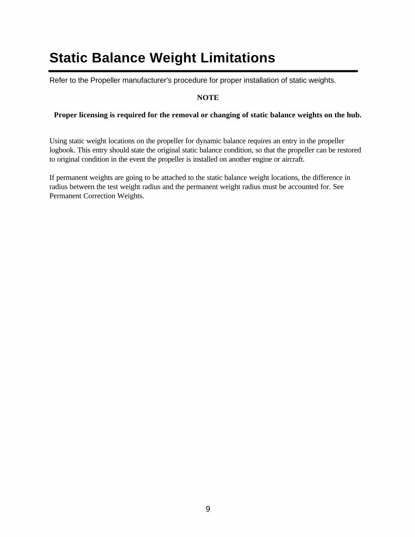
Static Balance Weight LimitationsRefer to the Propeller manufacturer's procedure for proper installation of static weights.
NOTE
Proper licensing is required for the removal or changing of static balance weights on the hub.
Using static weight locations on the propeller for dynamic balance requires an entry in the propellerlogbook. This entry should state the original static balance condition, so that the propeller can be restoredto original condition in the event the propeller is installed on another engine or aircraft.
If permanent weights are going to be attached to the static balance weight locations, the difference inradius between the test weight radius and the permanent weight radius must be accounted for. SeePermanent Correction Weights.

10
Documents and Placards
There must be a placard installed on the propeller assembly stating the propeller has been dynamicallybalanced and is indexed to the crankshaft of the engine (see example below). An indelible index markshall be made on all engine and crankshaft components that are visible.An entry will be made in the appropriate logbook showing the following:
1. Date2. Engine Hours3. Final balance vibration in Inches Per Second (IPS)4. Location of the mass trim weights in degrees from the index mark5. Signature and certificate number of mechanic
Example of placard to be placed on propeller assembly.
Modification of the spinner bulkhead, either by drilling or adding weights in the form of nuts,bolts, washers, or any combination thereof, requires the completion of FAA Form 337 forreturn to service.
11
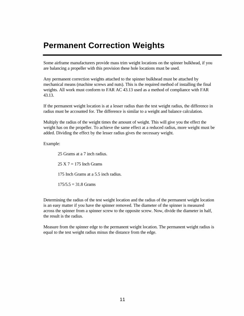
Permanent Correction Weights
Some airframe manufacturers provide mass trim weight locations on the spinner bulkhead, if youare balancing a propeller with this provision these hole locations must be used.
Any permanent correction weights attached to the spinner bulkhead must be attached bymechanical means (machine screws and nuts). This is the required method of installing the finalweights. All work must conform to FAR AC 43.13 used as a method of compliance with FAR43.13.
If the permanent weight location is at a lesser radius than the test weight radius, the difference inradius must be accounted for. The difference is similar to a weight and balance calculation.
Multiply the radius of the weight times the amount of weight. This will give you the effect theweight has on the propeller. To achieve the same effect at a reduced radius, more weight must beadded. Dividing the effect by the lesser radius gives the necessary weight.
Example:
25 Grams at a 7 inch radius.
25 X 7 = 175 Inch Grams
175 Inch Grams at a 5.5 inch radius.
175/5.5 = 31.8 Grams
Determining the radius of the test weight location and the radius of the permanent weight locationis an easy matter if you have the spinner removed. The diameter of the spinner is measuredacross the spinner from a spinner screw to the opposite screw. Now, divide the diameter in half,the result is the radius.
Measure from the spinner edge to the permanent weight location. The permanent weight radius isequal to the test weight radius minus the distance from the edge.
12
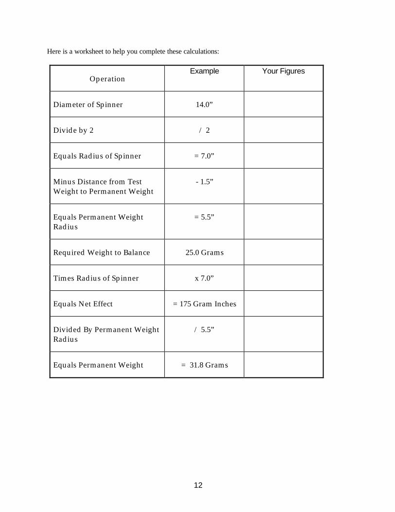
Here is a worksheet to help you complete these calculations:
OperationExample Your Figures
Diameter of Spinner 14.0”
Divide by 2 / 2
Equals Radius of Spinner = 7.0”
Minus Distance from TestWeight to Permanent Weight
- 1.5”
Equals Permanent WeightRadius
= 5.5”
Required Weight to Balance 25.0 Grams
Times Radius of Spinner x 7.0”
Equals Net Effect = 175 Gram Inches
Divided By Permanent WeightRadius
/ 5.5”
Equals Permanent Weight = 31.8 Grams
13
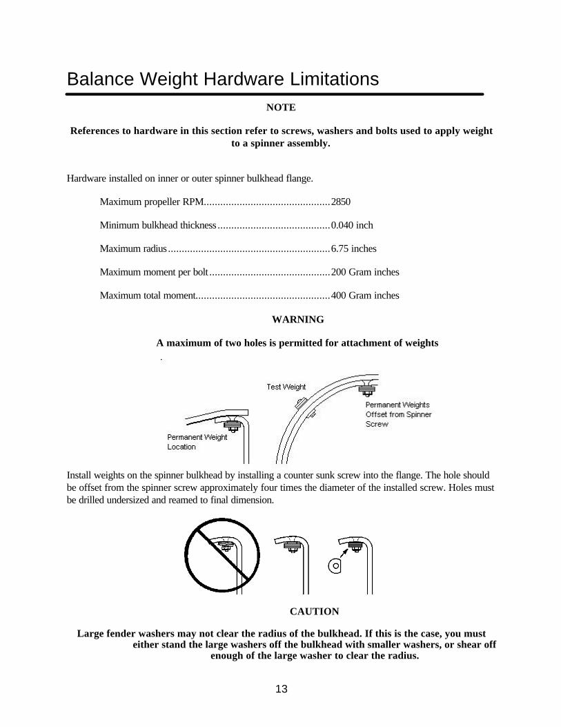
Balance Weight Hardware LimitationsNOTE
References to hardware in this section refer to screws, washers and bolts used to apply weightto a spinner assembly.
Hardware installed on inner or outer spinner bulkhead flange.
Maximum propeller RPM..............................................2850
Minimum bulkhead thickness .........................................0.040 inch
Maximum radius ...........................................................6.75 inches
Maximum moment per bolt ............................................200 Gram inches
Maximum total moment.................................................400 Gram inches
WARNING
A maximum of two holes is permitted for attachment of weights
Install weights on the spinner bulkhead by installing a counter sunk screw into the flange. The hole shouldbe offset from the spinner screw approximately four times the diameter of the installed screw. Holes mustbe drilled undersized and reamed to final dimension.
CAUTION
Large fender washers may not clear the radius of the bulkhead. If this is the case, you musteither stand the large washers off the bulkhead with smaller washers, or shear off
enough of the large washer to clear the radius.
14
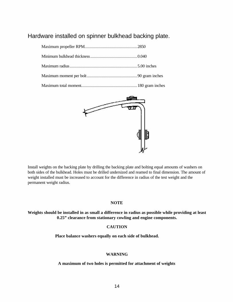
Hardware installed on spinner bulkhead backing plate.
Maximum propeller RPM..............................................2850
Minimum bulkhead thickness .........................................0.040
Maximum radius ...........................................................5.00 inches
Maximum moment per bolt ............................................90 gram inches
Maximum total moment.................................................180 gram inches
Install weights on the backing plate by drilling the backing plate and bolting equal amounts of washers onboth sides of the bulkhead. Holes must be drilled undersized and reamed to final dimension. The amount ofweight installed must be increased to account for the difference in radius of the test weight and thepermanent weight radius.
NOTE
Weights should be installed in as small a difference in radius as possible while providing at least0.25” clearance from stationary cowling and engine components.
CAUTION
Place balance washers equally on each side of bulkhead.
WARNING
A maximum of two holes is permitted for attachment of weights
15
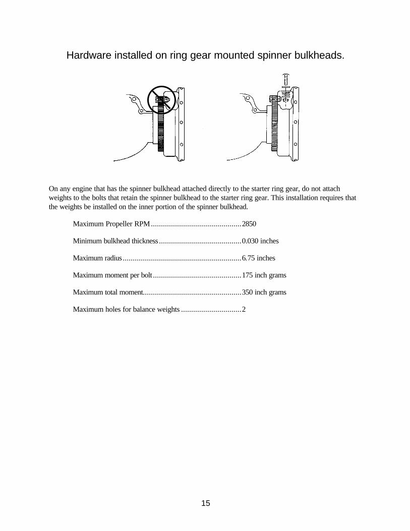
Hardware installed on ring gear mounted spinner bulkheads.
On any engine that has the spinner bulkhead attached directly to the starter ring gear, do not attachweights to the bolts that retain the spinner bulkhead to the starter ring gear. This installation requires thatthe weights be installed on the inner portion of the spinner bulkhead.
Maximum Propeller RPM.............................................2850
Minimum bulkhead thickness .........................................0.030 inches
Maximum radius ...........................................................6.75 inches
Maximum moment per bolt ............................................175 inch grams
Maximum total moment.................................................350 inch grams
Maximum holes for balance weights ..............................2

16
Hardware installed on starter ring gears.
Weights can be attached to some starter ring gears. A bolt and weight may be installed if the ring gear hasequally spaced, unoccupied holes.
CAUTION
If the ring gear has countersunk holes on the engine side, an appropriatecountersunk bolt must be used.
CAUTION
All bolts are installed from the engine side of the ring gear. No washers are to beinstalled under the head of the bolt.
Lycoming installations that use a long spacer between the ring gear and the propeller may not respondcorrectly to weights applied to the ring gear. These installations require that the balance weights beattached on the spinner bulkhead.

17
The Balance Job
NOTE
For detailed information on operating the balancer, refer to the operator's or ownersmanual supplied with the balancer.
Following are some general rules that will help you accomplish a balance job in a minimum amount timewith the maximum results.
CAUTION
Always chock the aircraft and perform engine run-ups on a hard clean surface.
Constant speed props should be run at a low cruise RPM, using minimum throttle or torque. Fixed pitchpropellers should be run at a low cruise RPM.
< 20 MPH
Wind speed should be limited to 20 MPH with a gust factor limited to 5 to 7 MPH. Attempting a balancingjob in wind stronger than this will be very difficult if not impossible.
18
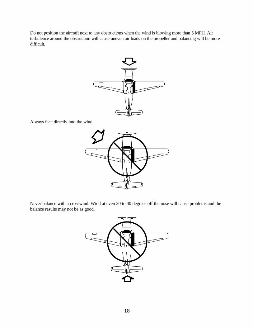
Do not position the aircraft next to any obstructions when the wind is blowing more than 5 MPH. Airturbulence around the obstruction will cause uneven air loads on the propeller and balancing will be moredifficult.
Always face directly into the wind.
Never balance with a crosswind. Wind at even 30 to 40 degrees off the nose will cause problems and thebalance results may not be as good.
19
Never balance with a tailwind. Wind over the tail of the aircraft affects the “Blade Pass Vibration” whichin turn affects the propeller at turning speed. This situation will lead to inconsistent reading and many runs.
Mechanical ProblemsIf you are sure you have done everything right, and you can't improve the vibration level at the propellerRPM -- YOU HAVE A MECHANICAL PROBLEM.
A variety of mechanical problems can show up at propeller turning speed these include:
• Propeller out of track.
• Crankshaft unbalance.
• Bearing problems.
• Loose or worn components in the engine.
• Defective crankshaft counterweights.
• Loose or worn components in the propeller hub.
• Loose airframe components.
The result of a mechanical problem is always the same; “IT JUST WON'T BALANCE.”
The natural reaction to this situation is to suspect that the balancing equipment is defective, the odds don'tfavor that conclusion. Trust the equipment, it has worked before and there's no reason to suspect it now.One simple test you can do to confirm that there is a mechanical problem is to remove any weights thatyou installed and run the engine again. If you don't have the same readings as the very first run, thevibration is caused by something other than propeller unbalance.
20
ConclusionUsing proper balancing tools, good workmanship, working on aircraft in good mechanical condition andfollowing the FARS you will be able to improve the running vibration of the engine and propellercombination on most aircraft.
The aircraft operator will see many benefits of reduced unscheduled maintenance, lower operating costsand more comfortable flights.