GUIDE TO MODEL SPECIFICATION CHANCE Civil … · A. B. Chance Company, HELICAL PIER® Foundation...
29
Guide to Model Specification – HELICAL TIEBACK ANCHORS – Earth Retention Hubbell Power Systems, Inc. © Copyright 2006 Hubbell, Inc. Bulletin 31-0503 Rev 08/14 1 GUIDE TO MODEL SPECIFICATION – CHANCE ® Civil Construction HELICAL TIEBACK ANCHORS FOR EARTH RETENTION TYPES OF SPECIFICATIONS The three types of specifications that are used for HELICAL TIEBACK ANCHOR projects are: Open Specifications: The Contractor is given the responsibility for the scope and design of the helical tieback anchor installation. In addition, the construction, capacity, and performance of the helical tieback anchor are the sole responsibility of the Contractor. This specification assumes that the Owner or Designer has provided the required structural loads. This specification type is most common for securing bids on temporary projects, and is not recommended for permanent applications. Performance Specifications: The Contractor is given the responsibility for certain design and/or construction procedures, but must demonstrate to the Owner through testing and/or mutually agreed upon acceptance criteria that the production helical tiebacks meet or exceed the specified performance parameters. This specification assumes that the location and the required loads of the helical tieback anchor have been specified. The Contractor and Owner share the responsibility for the work. Prescriptive Specifications: The Owner has the sole responsibility for the scope and design of the helical tieback anchor installation and specifies the procedures that must be followed. Prescriptive specifications mandate the Owner to be responsible for the proper performance of the production helical tieback anchors. The Contractor is responsible for fulfilling the obligations/details as specified in the construction documents. Performance specifications are the most common and allow Contractors to use their unique installation methods and experience for any given site conditions. Owners receive the benefit of value engineering, which can result in lower costs. The Owner, Designer, and Contractor will be jointly responsible for the design, installation, acceptance, and performance of the helical tieback anchor. The installation of a helical tieback requires specialized equipment, techniques, and trained work crews. Every detail of the work cannot be specified, and every potential problem cannot be anticipated. Therefore, a contractor trained in the proper methods of design and installation of screw anchor tiebacks must be selected. A list of the major tasks to be performed on a helical tieback anchor project is shown in Table-1 of the Model Specifications. The Owner or his representative should select the type of specification and procurement method. The responsible party for each task must be identified and mutually agreed upon at the earliest point in the contracting process. The completed Table-1 should be included in the construction documents.
Transcript of GUIDE TO MODEL SPECIFICATION CHANCE Civil … · A. B. Chance Company, HELICAL PIER® Foundation...

Guide to Model Specification –
HELICAL TIEBACK ANCHORS – Earth Retention
Hubbell Power Systems, Inc. ©Copyright 2006 Hubbell, Inc. Bulletin 31-0503 Rev 08/14
1
GUIDE TO MODEL SPECIFICATION –
CHANCE® Civil Construction
HELICAL TIEBACK ANCHORS FOR EARTH
RETENTION
TYPES OF SPECIFICATIONS
The three types of specifications that are used for HELICAL TIEBACK ANCHOR projects are:
Open Specifications: The Contractor is given the responsibility for the scope and design of the helical
tieback anchor installation. In addition, the construction, capacity, and performance of the helical tieback
anchor are the sole responsibility of the Contractor. This specification assumes that the Owner or Designer
has provided the required structural loads. This specification type is most common for securing bids on
temporary projects, and is not recommended for permanent applications.
Performance Specifications: The Contractor is given the responsibility for certain design and/or
construction procedures, but must demonstrate to the Owner through testing and/or mutually agreed upon
acceptance criteria that the production helical tiebacks meet or exceed the specified performance parameters.
This specification assumes that the location and the required loads of the helical tieback anchor have been
specified. The Contractor and Owner share the responsibility for the work.
Prescriptive Specifications: The Owner has the sole responsibility for the scope and design of the helical
tieback anchor installation and specifies the procedures that must be followed. Prescriptive specifications
mandate the Owner to be responsible for the proper performance of the production helical tieback anchors.
The Contractor is responsible for fulfilling the obligations/details as specified in the construction documents.
Performance specifications are the most common and allow Contractors to use their unique installation
methods and experience for any given site conditions. Owners receive the benefit of value engineering,
which can result in lower costs.
The Owner, Designer, and Contractor will be jointly responsible for the design, installation, acceptance, and
performance of the helical tieback anchor. The installation of a helical tieback requires specialized
equipment, techniques, and trained work crews. Every detail of the work cannot be specified, and every
potential problem cannot be anticipated. Therefore, a contractor trained in the proper methods of design and
installation of screw anchor tiebacks must be selected.
A list of the major tasks to be performed on a helical tieback anchor project is shown in Table-1 of the Model
Specifications. The Owner or his representative should select the type of specification and procurement
method. The responsible party for each task must be identified and mutually agreed upon at the earliest point
in the contracting process. The completed Table-1 should be included in the construction documents.

Guide to Model Specification –
HELICAL TIEBACK ANCHORS – Earth Retention
Hubbell Power Systems, Inc. ©Copyright 2006 Hubbell, Inc. Bulletin 31-0503 Rev 08/14
2
The process of continuous communication between all the parties involved is essential to achieve a
satisfactory result. Clear communication and close cooperation are particularly important in the start-up
phase and in testing. In addition, a timely preparation and review of all submittals is critical.
This model specification can be adapted to each of the three types of specifications. However, it is primarily
written for the performance type. The identity of the “Contractor” and the “Owner” is always well defined,
unlike that of the “Designer” or “Engineer”. For example, the “Engineer” may be an employee(s) of the
Contractor, or a third party consultant hired to secure a lower cost alternative during the bidding process. In
contrast, the “Engineer” may be the Owner, an employee(s) of the Owner, or a representative hired by the
Owner. It is recommended that the Engineer be a third party agency employed by the Owner to serve in the
owner's best interests during the various stages of the contract.
For purposes of this Model Specification, the subject is a high capacity HELICAL TIEBACK ANCHOR
manufactured by CHANCE Civil Construction. The helical tieback anchor consists of one or more helical
bearing plates attached at the tip of a high strength central steel shaft. The central steel shaft consists of solid
square shaft of various sections. Said shaft is connected to the wall face via thread-bar, bearing plate, and
load nut.
It is suggested that the specification writer accurately and
completely modify this model to suit his/her particular case.
Items in italics as such may be considered as “Commentary” and as such may be deleted or retained to suit
the needs of the specification writer.

Guide to Model Specification –
HELICAL TIEBACK ANCHORS – Earth Retention
Hubbell Power Systems, Inc. ©Copyright 2006 Hubbell, Inc. Bulletin 31-0503 Rev 08/14
3
The following is list of general references that will provide additional background to HELICAL TIEBACK
ANCHOR technology:
A. B. Chance Company, HELICAL PIER® Foundation Systems, Technical Manual, Bulletin 01-9601,
Copyright 2000 Hubbell, 210 North Allen St., Centralia, MO 65240
Atlas Systems, Inc., Technical Manual, 2005, Copyright 2004 – Atlas Systems, Inc, 1026-B South Powell
Road, Independence, MO 64056
Bobbitt, D.E., and Thorsten, Richard, The Use of Helical Tieback Anchors for a Permanent Retaining Wall,
Bulletin 31-8902, Presented at the 1989 Foundation Congress – Northwestern University – Evanston, Illinois
Seider, Gary L., and Smith, Walter P., Helical Tieback Anchors Help Reconstruct Failed Sheet Pile Wall,
Bulletin 31-9502, Presented at the 1995 46th Highway Geology Symposium – Charleston, West Virginia
Hoyt, R.M. and Clemence, S.P., 1989. Uplift Capacity of Helical Anchors in Soil. Proceedings of the 12th
International Conference on Soil Mechanics and Foundation Engineering, Vol. 2, pp. 1019-1022.
Clemence, S.P., Thorsten, Richard E., and Edwards, Bill, Helical Anchors: Overview of Application and
Design, Bulletin 31-9001, reprinted from ADSC Foundation Drilling Magazine, Copyright 1990 A. B. Chance
Company, 210 North Allen St., Centralia, MO 65240
Figure-1 Typical Cross Section

Guide to Model Specification –
HELICAL TIEBACK ANCHORS – Earth Retention
Hubbell Power Systems, Inc. ©Copyright 2006 Hubbell, Inc. Bulletin 31-0503 Rev 08/14
4
CHANCE® Civil Construction
HELICAL TIEBACK ANCHORS
MODEL SPECIFICATION
1. GENERAL
1.1 Purpose of Specification
The purpose of this specification is to detail the furnishing of all designs, materials, tools, equipment, labor
and supervision, and installation techniques necessary to install HELICAL TIEBACK ANCHORS as
detailed on the drawings, including connection details. This shall include provisions for load testing that
may be part of the scope of work
Specifier Note: This specification may require modification to account for unusual and/or unforeseen site
and subsurface conditions and the particular circumstances of the project.
1.2 Scope of Work
This work consists of furnishing all necessary engineering and design services (if required), supervision,
labor, tools, materials, and equipment to perform all work necessary to install the HELICAL TIEBACK
ANCHORS, at (location, City, State/Province) for (Company, State or Private Authority) per the
specifications described herein, and as shown on the drawings. The Contractor shall install a helical anchor
that will develop the load capacities as detailed on the drawings. This may also include provisions for load
testing to verify tieback capacity and deflection, if part of the scope of work. The responsibilities and duties
of the respective parties for this project are summarized in Table-1.

Guide to Model Specification –
HELICAL TIEBACK ANCHORS – Earth Retention
Hubbell Power Systems, Inc. ©Copyright 2006 Hubbell, Inc. Bulletin 31-0503 Rev 08/14
5
Table-1. Tasks and Responsibilities to be Allocated for Helical Tieback Anchor Work
TASK RESPONSIBLE
PARTY*
1 Site Investigation, Geotechnical Investigation, Site Survey, and potential
work restrictions
2 Type of specification, requirement for a pre-contract testing program, and
procurement method
3 Obtaining easements
4 Overall scope of work, design of the anchored structure – including
design loads (vertical, horizontal, etc.), anchor locations, and anchor
spacing and orientation
5 Definition and qualification of safety factors
6 Calculation/estimation of allowable structural and/or anchor movement in
service (acceptance criteria)
7 Definition of service life (temporary – months or permanent - years) and
required degree of corrosion protection based on site conditions
8 Type and number of tests (pre-contract, pre-production and production)
9 Minimum total anchor length, depth to bearing stratum
10 Helical Tieback Anchor components and details
11 Details of corrosion protection, if required
12 Details of anchor connection to structure (e.g., for static and seismic
conditions)
13 Preparation of Drawings and test reports
14 Evaluation of test results
15 Construction methods, schedule, sequencing, and coordination of work
16 Requirements of field production control, including logging of installation
torque vs. installed depth
17 Supervision of work
18 Long-term monitoring
* To be filled in by specification writer.
1.3 Qualifications of the Helical Tieback Anchor Contractor
The helical anchor Contractor shall be experienced in performing design and construction of helical tieback
anchors and shall furnish all materials, labor, and supervision to perform the work. The Contractor shall be
trained by CHANCE® Civil Construction in the proper methods of design and installation of screw anchor
tiebacks. The Contractor shall provide names of on-site personnel materially involved with the work. At a
minimum, these personnel shall include foreman, machine operator, and project engineer/manager.
The helical tieback anchor Contractor shall not sublet the whole or any part of the contract without the
express written permission of the Owner.

Guide to Model Specification –
HELICAL TIEBACK ANCHORS – Earth Retention
Hubbell Power Systems, Inc. ©Copyright 2006 Hubbell, Inc. Bulletin 31-0503 Rev 08/14
6
1.4 Related Project Specifications
To be determined by the specification writer.
1.5 Definitions
A partial list follows. The Owner may wish to add other specific, project-related items.
Bearing Stratum: Soil layer(s) of sufficient strength capable of resisting the applied axial load transferred
by the helical tieback.
Contractor: The person/firm responsible for performing the helical tieback anchor work.
Coupling: Central steel shaft connection means formed as integral part of the plain extension shaft material.
For Type SS anchors, couplings are external cast sleeves, or hot upset forged sockets.
Coupling Bolt(s): High strength, structural steel fasteners used to connect helical anchor segments together.
For Type SS segments, the coupling bolt transfers axial load only.
Design Load (DL): Maximum anticipated service load applied to the helical anchor. A.k.a. Working Load
(WL).
Free Length: Length of plain extension acting as a tendon, which is free to elongate elastically. A.k.a. un-
bonded length or stressing length. Helix plates shall not be located in free length section of tieback.
Minimum free length shall be specified on a project specific basis.
Helical Extension: Helical tieback anchor component installed immediately following the lead or starter
section, if required. This component consists of one or more helix plates welded to a central steel shaft of
finite length. Function is to increase bearing area.
Helical Tieback Anchor: Bearing type anchor used to transfer tensile loads to soil. Helical tieback anchors
consist of a central steel shaft, helix bearing plates, coatings, corrosion protection, and a wall connection.
Helix Plate: Generally round steel plate formed into a ramped spiral. The helical shape provides the means
to install the helical tieback anchor, plus the plate transfers load to soil in end-bearing. Helix plates are
available in various diameters and thicknesses.
Lead Section: The first helical tieback anchor component installed into the soil, consisting of single or
multiple helix plates welded to a central steel shaft. A.k.a Starter Section.
Performance Test: Similar to a Proof Test except a cyclic loading method is used to analyze total, elastic,
and net movement of the helical anchor. Often used for pre-contract or pre-production load tests, in addition
to a specified percentage of production anchors.

Guide to Model Specification –
HELICAL TIEBACK ANCHORS – Earth Retention
Hubbell Power Systems, Inc. ©Copyright 2006 Hubbell, Inc. Bulletin 31-0503 Rev 08/14
7
Plain Extension: Central steel shaft of finite length without helix plates. It is installed following the
installation of the lead or starter section or helical extension (if used). The units are connected with
couplings and bolts. Plain extensions are used to extend the helix plates beyond the specified minimum free
length and into competent load bearing stratum.
Proof Test: Incremental loading of a helical anchor, holding for a period of time, and recording the total
movement at each load increment.
Safety Factor: The ratio of the ultimate capacity to the working or design load used for the design of any
structural element.
Square Shaft (SS): Solid steel, round-cornered-Square central Shaft elements ranging in size from 1-1/4” to
2-1/4”. A.k.a. Type SQ.
Thread Bar Adapter: Section of central steel shaft used to connect the helical anchor to the wall face via a
high tensile strength pre-stressing thread bar.
Torque Strength Rating: The maximum torque energy that can be applied to the helical tieback anchor
during installation in soil, a.k.a. allowable, or safe torque.
1.6 Allowable Tolerances
The tolerances quoted in this section are suggested maximums. The actual values established for a particular
project will depend on the structural application.
1.6.1 Centerline of helical tieback anchor shall not be more than 6 inches from indicated plan location.
1.6.2 The angular tolerance between installed tieback anchor angle and design angle shall be 3 as shown
on the drawings.
1.7 Quality Assurance
1.7.1 Contractors authorized by CHANCE Civil Construction shall install helical tieback anchors. These
Contractors shall have satisfied the requirements relative to the technical aspects of the product and
installation procedures as therein specified.
1.7.2 The Contractor shall employ an adequate number of skilled workers who are experienced in the
necessary crafts and who are familiar with the specified requirements and methods needed for proper
performance of the work of this specification.
1.7.3 All helical tieback anchors shall be installed in the presence of a designated representative of the
Owner unless said representative informs the Contractor otherwise. The designated representative
shall have the right of access to any and all field installation records and test reports.

Guide to Model Specification –
HELICAL TIEBACK ANCHORS – Earth Retention
Hubbell Power Systems, Inc. ©Copyright 2006 Hubbell, Inc. Bulletin 31-0503 Rev 08/14
8
1.7.4 Screw anchor components as specified therein shall be manufactured by a facility whose quality
systems comply with ISO (International Organization of Standards) 9001 requirements. Certificates
of Registration denoting ISO Standards Number shall be presented upon request to the Owner or their
representative.
1.7.5 CHANCE Civil Construction provides a standard one-year warranty on materials and workmanship
of the product. Any additional warranty provided by the Contractor shall be issued as an addendum
to this specification.
1.7.6 Design of helical tieback anchors shall be performed by an entity as required in accordance with
existing local code requirements or established local practices. This design work may be performed
by a licensed professional engineer, an authorized CHANCE Civil Construction Contractor, or
designer depending upon local requirements or practices.
1.8 Design Criteria
1.8.1 Helical tieback anchors shall be designed to meet the specified loads and acceptance criteria as shown
on the drawings. The calculations and drawings required from the Contractor or Engineer shall be
submitted to the Owner for review and acceptance in accordance to Section 3.1 “Construction
Submittals”.
1.8.1.1 The allowable working load on the helical tieback anchor shall not exceed the following values:
Pallowt = Sut / FS
Where:Pallowt = allowable working load in tension (kip)
Sut = Min. ultimate tensile strength of central steel shaft segment (at coupling joint) (kip)
FS = factor of safety suitable for application, i.e. temporary or permanent structures
For permanent applications, it is recommended to use a factor of safety of two (2). For temporary
applications, factor of safety typically ranges between 1.25 and 1.5.
It is recommended to use the minimum ultimate tensile strengths as published by CHANCE Civil
Construction (shown in Table-A of the Appendix). The ultimate tensile strength may be reduced by
the ultimate capacity per helix plate(s) – depending on the number of helix plates specified and type
of shaft product used. The ultimate tensile strength may also be reduced by the torque limited
ultimate capacity – depending on the type of shaft product used.
1.8.1.2 The ultimate structural capacity shall be determined as:
Pultt = Sut
Where: Pultt = Ultimate structural capacity in tension (kip)

Guide to Model Specification –
HELICAL TIEBACK ANCHORS – Earth Retention
Hubbell Power Systems, Inc. ©Copyright 2006 Hubbell, Inc. Bulletin 31-0503 Rev 08/14
9
Sut = Minimum ultimate tensile strength of central steel shaft (kip)
It is recommended to use the minimum ultimate tensile strengths as published by CHANCE Civil
Construction (shown in Table-A of the Appendix). The ultimate tensile strength may be reduced by
the ultimate capacity per helix plate(s) – depending on the number of helix plates specified and type
of shaft family used. The ultimate tensile strength may also be reduced by the torque limited ultimate
capacity – depending on the type of shaft family used.
The minimum yield strength of the central steel shaft is as follows: Type SS5: 70 ksi; Type SS125,
SS1375, SS150, SS175, SS200, SS225: 90 ksi.
1.8.2 Individual helical tieback anchors shall be designed so that the maximum test load will not exceed 90
percent of the minimum ultimate tension capacity of the central steel shaft material. The Contractor
shall select the type of thread bar to be used. The thread bar shall be sized so the design load does not
exceed 60 percent of the guaranteed ultimate tensile strength of the thread bar. In addition, the thread
bar shall be sized so the maximum test load does not exceed 80 percent of the guaranteed ultimate
tensile strength of the thread bar.
1.8.3 Helical tieback anchor capacity in soil shall not be relied upon from the following soil layers as
defined in the geotechnical reports:
________________________________________________________________________________
________________________________________________________________________________
The overall length and installed torque of a helical tieback anchor shall be specified such that the
required in-soil capacity is developed by end-bearing on the helix plate(s) in an appropriate strata(s).
It is recommended that the theoretical end-bearing capacity of the helix plates be determined using
HeliCAP® Engineering Software or equal commercially available software. The required soil
parameters (c, , , or N-values) for use with HeliCAP® or equal shall be provided in the geotechnical
reports. The Owner shall determine the allowable response to axial loads.
Helical anchors are not suited for solid, competent rock, but the helix plates can penetrate into dense
bearing soils. Appropriate and repeatable installation techniques and helical anchor termination
criteria must be identified and verified in the field.

Guide to Model Specification –
HELICAL TIEBACK ANCHORS – Earth Retention
Hubbell Power Systems, Inc. ©Copyright 2006 Hubbell, Inc. Bulletin 31-0503 Rev 08/14
10
1.8.4 Corrosion Protection
This section is optional (see below). Provisions of this section and Section 4.7 below may not be
required in the Specification. If this section is not used, then Section 4.7 should likewise be
deleted. The degree and extent of corrosion protection must be specified by the Owner (Table-1).
Corrosion protection is a function of structure type, service life, and the overall aggressiveness of the
project soils. The need for corrosion protection of helical tieback anchors must be carefully
determined and specified as necessary.
Corrosion resistant coatings (i.e. epoxy, plastic sheath) on the lead/starter section are impractical
due to abrasive action wearing off the coating as the soil flows over the helix plates and around the
central steel shaft. Hot dip galvanization is the only practical means to provide a corrosion resistant
coating capable of withstanding the rigors of installation. Extension sections are typically hot-dip
galvanized, but other coatings can be specified.
The following requirements are typical. The specifier should review and edit as appropriate for the
project.
Structure Type: _________________________ (e.g. temporary, permanent) with a temporary
structure being defined within a specified time frame (i.e. months rather than years). In general,
permanent structures have a service life greater than 24 months.
Temporary structures do not require corrosion protection.
Service Life: ____________________________(years) a typical service life of 50 years should be
used unless otherwise specified. If the service life of a temporary helical tieback anchor is likely to
be extended due to construction delays, it should be considered permanent.
For a service life of less than 20 years in non-aggressive soil, corrosion protection is not
recommended.
Corrosion protection requirements for the various helical tieback anchor elements shall be provided
meeting the requirements of Table-B in the Appendix for:
Soil: ____________________________________ Aggressive or Non-Aggressive with optional
location and elevation limits defined by the Specifier.
For guidance on aggressiveness classification, see Table-B in the Appendix. It is recommended to
retain the services of a corrosion design professional for very aggressive soils.
Guide to Model Specification –
HELICAL TIEBACK ANCHORS – Earth Retention
Hubbell Power Systems, Inc. ©Copyright 2006 Hubbell, Inc. Bulletin 31-0503 Rev 08/14
11
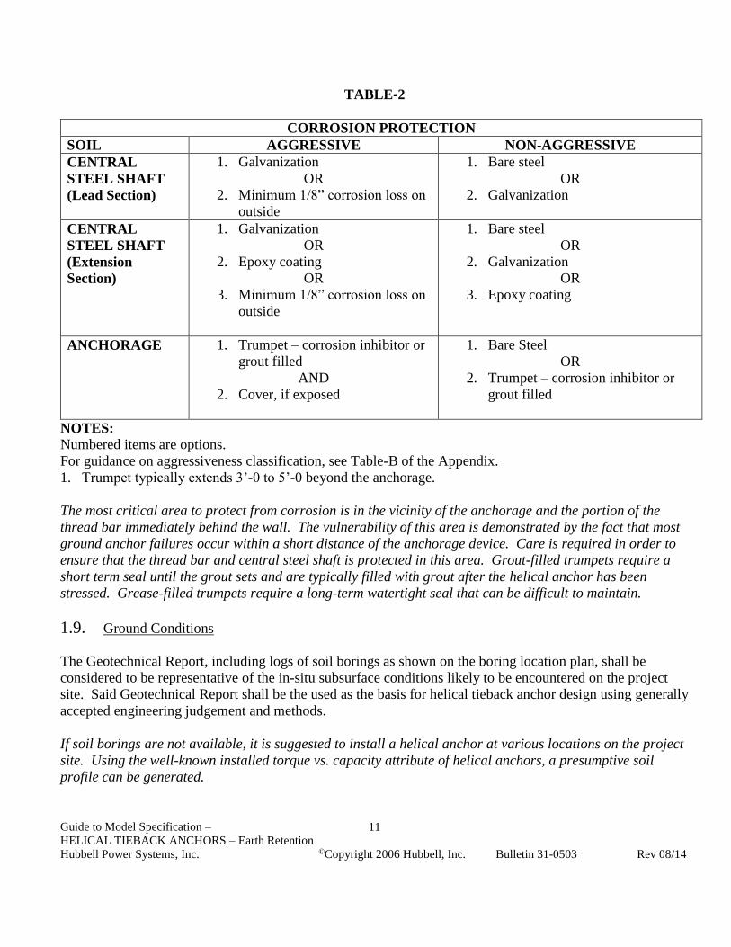
TABLE-2
CORROSION PROTECTION
SOIL AGGRESSIVE NON-AGGRESSIVE
CENTRAL
STEEL SHAFT
(Lead Section)
1. Galvanization
OR
2. Minimum 1/8” corrosion loss on
outside
1. Bare steel
OR
2. Galvanization
CENTRAL
STEEL SHAFT
(Extension
Section)
1. Galvanization
OR
2. Epoxy coating
OR
3. Minimum 1/8” corrosion loss on
outside
1. Bare steel
OR
2. Galvanization
OR
3. Epoxy coating
ANCHORAGE 1. Trumpet – corrosion inhibitor or
grout filled
AND
2. Cover, if exposed
1. Bare Steel
OR
2. Trumpet – corrosion inhibitor or
grout filled
NOTES:
Numbered items are options.
For guidance on aggressiveness classification, see Table-B of the Appendix.
1. Trumpet typically extends 3’-0 to 5’-0 beyond the anchorage.
The most critical area to protect from corrosion is in the vicinity of the anchorage and the portion of the
thread bar immediately behind the wall. The vulnerability of this area is demonstrated by the fact that most
ground anchor failures occur within a short distance of the anchorage device. Care is required in order to
ensure that the thread bar and central steel shaft is protected in this area. Grout-filled trumpets require a
short term seal until the grout sets and are typically filled with grout after the helical anchor has been
stressed. Grease-filled trumpets require a long-term watertight seal that can be difficult to maintain.
1.9. Ground Conditions
The Geotechnical Report, including logs of soil borings as shown on the boring location plan, shall be
considered to be representative of the in-situ subsurface conditions likely to be encountered on the project
site. Said Geotechnical Report shall be the used as the basis for helical tieback anchor design using generally
accepted engineering judgement and methods.
If soil borings are not available, it is suggested to install a helical anchor at various locations on the project
site. Using the well-known installed torque vs. capacity attribute of helical anchors, a presumptive soil
profile can be generated.

Guide to Model Specification –
HELICAL TIEBACK ANCHORS – Earth Retention
Hubbell Power Systems, Inc. ©Copyright 2006 Hubbell, Inc. Bulletin 31-0503 Rev 08/14
12
The Geotechnical Report shall be provided for purposes of bidding. If during helical tieback anchor
installation, subsurface conditions of a type and location are encountered of a frequency that were not
reported, inferred and/or expected at the time of preparation of the bid, the additional costs required to
overcome such conditions shall be considered as extras to be paid for.
All available information related to subsurface and general site conditions should be made available to all
bidders at the time of bid preparation. It is not reasonable to expect bidders to conduct supplemental site
investigations at their own risk and cost prior to bidding, unless the specific contract requirements call for it
(Table-1) and provide for appropriate compensation. A mandatory site visit and pre-bid meeting should be
held so that the details of the project and the specifications can be thoroughly discussed. These steps will
help avoid technical and contractual problems developing during the execution of the work, and will help all
parties manage their respective risk.
2 REFERENCED CODES AND STANDARDS
Standards listed by reference, including revisions by issuing authority, form a part of this specification
section to the extent indicated. Standards listed are identified by issuing authority, authority abbreviation,
designation number, title, or other designation established by issuing authority. Standards subsequently
referenced herein are referred to by issuing authority abbreviation and standard designation. In case of
conflict, the particular requirements of this specification shall prevail. The latest publication as of the issue
of this specification shall govern, unless indicated otherwise.
2.1 American Society for Testing and Materials (ASTM):
2.1.1 ASTM A29/A29M Steel Bars, Carbon and Alloy, Hot-Wrought and Cold Finished.
2.1.2 ASTM A36/A36M Structural Steel.
2.1.3 ASTM A53 Pipe, Steel, Black and Hot-Dipped, Zinc-Coated Welded and Seamless.
2.1.4 ASTM A153 Zinc Coating (Hot Dip) on Iron and Steel Hardware.
2.1.5 ASTM A252 Welded and Seamless Steel Pipe Piles.
2.1.6 ASTM A775 Electrostatic Epoxy Coating
2.1.7 ASTM A193/A193M Alloy-Steel and Stainless Steel Bolting Materials for High Temperature
Service.
2.1.8 ASTM A320/A320M Alloy-Steel Bolting Materials for Low Temperature Service.
2.1.9 ASTM A325 Standard Specification for Structural Bolts, Steel, Heat Treated, 120/105 ksi Minimum
Tensile Strength.
2.1.10 ASTM A500 Cold-Formed Welded and Seamless Carbon Steel Structural Tubing in Rounds and
Shapes.
2.1.11 ASTM A536 Standard Specifications for Ductile Iron Castings
2.1.12 ASTM A572 HSLA Columbium-Vanadium Steels of Structural Quality.
2.1.13 ASTM A615 Standard Specification for Deformed and Plain Steel Bars for Concrete Reinforcement
2.1.14 ASTM A656 Hot-Rolled Structural Steel, High-Strength Low-Alloy Plate with Improved
Formability.
2.1.15 ASTM A958 Standard Specification for Steel Castings, Carbon, and Alloy, with Tensile
Requirements, Chemical Requirements Similar to Wrought Grades.
Guide to Model Specification –
HELICAL TIEBACK ANCHORS – Earth Retention
Hubbell Power Systems, Inc. ©Copyright 2006 Hubbell, Inc. Bulletin 31-0503 Rev 08/14
13
2.1.16 ASTM A1018 Steel, Sheet and Strip, Heavy Thickness Coils, Hot Rolled, Carbon, Structural, High-
Strength Low-Alloy, Columbium or Vanadium, and High-Strength Low-Alloy with Improved
Formability.
2.1.17 ASTM D1784 Specification for Rigid Poly Vinyl Chloride (PVC) Compounds and Chlorinated Poly
Vinyl Chloride (CPVC) Compounds.
2.1.18 ASTM D1785 Specification for Poly(Vinyl Chloride) (PVC) Plastic Pipe, Schedules 40, 80, and 120.
2.1.19 ASTM D3034 Specification for Type PSM Poly(Vinyl Chloride) (PVC) Sewer Pipe and Fittings.
2.1.20 ASTM D3689 Method of Testing Individual Piles Under Static Axial Tensile Load.
2.2 American Welding Society (AWS):
2.2.1 AWS D1.1 Structural Welding Code – Steel.
2.2.2 AWS D1.2 Structural Welding Code – Reinforcing Steel.
2.3 American Society of Civil Engineers (ASCE):
2.3.1 ASCE 20-96 Standard Guidelines for the Design and Installation of Pile Foundations.
2.4 Association of Drilled Shaft Contractors (ADSC) The International Association of Foundation
Drilling:
2.4.1 GEC No. 4 - Ground Anchors and Anchored Systems
2.4.2 ADSC Mechanical Anchor Product Data
2.5 Post Tensioning Institute (PTI):
2.5.1 Recommendations for Prestressed Rock and Soil Anchors, Third Edition, Copyright 1996 By the
Post-Tensioning Institute.
2.6 Society of Automotive Engineers (SAE):
2.6.1 SAE J429 Mechanical and Material Requirements for Externally Threaded Fasteners.
3 SUBMITTALS
3.1 Construction Submittals
3.1.1 The Contractor or Engineer shall prepare and submit to the Owner, for review and approval, working
drawings and design calculations for the helical tieback anchor intended for use at least 14 calendar
days prior to planned start of construction (but note also Paragraph 3.1.8). All submittals shall be
signed and sealed by a Registered Professional Engineer currently licensed in the State/Province of
__________________________.
3.1.2 The Contractor shall submit a detailed description of the construction procedures proposed for use to
the Owner for review. This shall include a list of major equipment to be used.
3.1.3 The Working Drawings shall include the following:
3.1.3.a Helical anchor number, location and pattern by assigned identification number
3.1.3.b Helical anchor design load

Guide to Model Specification –
HELICAL TIEBACK ANCHORS – Earth Retention
Hubbell Power Systems, Inc. ©Copyright 2006 Hubbell, Inc. Bulletin 31-0503 Rev 08/14
14
3.1.3.c Type and size of central steel shaft
Type SS125 1-1/4” RCS, Type SS1375 1-3/8” RCS, Type SS5/SS150 – 1-1/2” RCS, Type SS175 – 1-3/4”
RCS, Type SS200 – 2” RCS, Type SS225 – 2-1/4” RCS.
3.1.3.d Helix configuration (number and diameter of helix plates)
3.1.3.e Minimum effective installation torque
3.1.3.f Minimum overall length
3.1.3.g Inclination of helical anchor
3.1.3.h Type and size of thread bar
If the number of helix plates per helical tieback anchor required for the project is not shown on the Working
Drawings, the Contractor shall have the option of performing subsurface tests using methods subject to the
review and acceptance of the Owner. The data collected along with other information pertinent to the
project site shall be used to determine the required helix configuration.
3.1.4 The Contractor shall submit shop drawings for all helical tieback anchor components and anchorage
details to the Owner for review and approval. This includes helical tieback anchor lead/starter and
extension section identification (manufacturer’s catalog numbers).
Shop drawings for helical tieback anchor components and standard anchorage connection details can be
obtained from CHANCE Civil Construction, their certified Distributors and Installing Contractors, or
directly from www.abchance.com or www.atlassys.com.
3.1.5 If required, the Contractor shall submit certified mill test reports for the central steel shaft, as the
material is delivered, to the Owner for record purposes. The ultimate strength, yield strength, %
elongation, and chemistry composition shall be provided.
3.1.6 The Contractor shall submit plans for pre-production (optional) and production testing for the helical
tieback anchors to the Owner for review and acceptance prior to beginning load tests. The purpose of
the test is to determine the load versus displacement response of the helical tieback anchor and
provide an estimation of ultimate capacity.
It is the responsibility of the structural engineer of record to establish acceptance criteria for helical tieback
anchor performance tests, which can be incorporated into the project specific specification. Load testing
also provides the means to verify the empirical ratio between the ultimate capacity and the average
installing torque of the helical tieback anchor for a specific project site.
3.1.7 The Contractor shall submit to the Owner copies of calibration reports for each torque indicator or
torque motor, and all load test equipment to be used on the project. The calibration tests shall have
been performed within forty five (45) working days of the date submitted. Helical tieback anchor
installation and testing shall not proceed until the Owner has received the calibration reports. These
calibration reports shall include, but are not limited to, the following information:
Guide to Model Specification –
HELICAL TIEBACK ANCHORS – Earth Retention
Hubbell Power Systems, Inc. ©Copyright 2006 Hubbell, Inc. Bulletin 31-0503 Rev 08/14
15
3.1.7.a Name of project and Contractor
3.1.7.b Name of testing agency
3.1.7.c Identification (serial number) of device calibrated
3.1.7.d Description of calibrated testing equipment
3.1.7.e Date of calibration
3.1.7.f Calibration data
Load test equipment includes load cylinders, pressure gauges, and load transducers. A. B. Chance
Mechanical Dial Torque Indicator (SKU C303-1340) is calibrated prior to final assembly. Its torsion bar
design eliminates the need for annual re-calibration.
3.1.8 Work shall not begin until all the submittals have been received and approved by the Owner. The
Contractor shall allow the Owner a reasonable time to review, comment, and return the submittal
package after a complete set has been received. All costs associated with incomplete or unacceptable
submittals shall be the responsibility of the Contractor.
3.2 Installation Records
The Contractor shall provide the Owner copies of helical tieback anchor installation records within 24 hours
after each installation is completed. Records shall be prepared in accordance with the specified division of
responsibilities as noted in Table-1. Formal copies shall be submitted on a weekly basis. These installation
records shall include, but are not limited to, the following information.
3.2.1 Name of project and Contractor
3.2.2 Name of Contractor’s supervisor during installation
3.2.3 Date and time of installation
3.2.4 Name and model of installation equipment
3.2.5 Type of torque indicator used
3.2.6 Location of helical anchor by assigned identification number
3.2.7 Elevation of anchorage
3.2.8 Actual helical tieback anchor type and configuration – including lead/starter section (number and size
of helix plates), number and type of extension sections (manufacturer’s SKU numbers)
3.2.9 Helical tieback anchor installation duration and observations
3.2.10 Total length of installed helical anchor
3.2.11 Inclination of helical anchor
3.2.12 Installation torque at one-foot intervals for the final 10 feet
3.2.13 Comments pertaining to interruptions, obstructions, or other relevant information
3.2.14 Rated load capacities
3.3 Test Reports
The Contractor shall provide the Owner copies of field test reports within 24 hours after completion of the
load tests. Records shall be prepared in accordance with the specified division of responsibilities as noted in
Table-1. Formal copies shall be submitted within a reasonable amount of time following test completion.

Guide to Model Specification –
HELICAL TIEBACK ANCHORS – Earth Retention
Hubbell Power Systems, Inc. ©Copyright 2006 Hubbell, Inc. Bulletin 31-0503 Rev 08/14
16
These test reports shall include, but are not limited to, the following information (note Section 6 – Helical
Anchor Load Tests).
3.3.1 Name of project and Contractor
3.3.2 Name of Contractor’s supervisor during installation
3.3.3 Name of third party test agency, if required
3.3.4 Date, time, and duration of test
3.3.5 Location of helical anchor by assigned identification number
3.3.6 Type of test (performance, proof)
3.3.7 Description of calibrated testing equipment and test set-up
3.3.8 Actual helical tieback anchor type and configuration – including lead/starter section, number and type
of extension sections (manufacturer’s SKU numbers)
3.3.9 Steps and duration of each load increment
3.3.10 Cumulative anchor-head movement at each load step
3.3.11 Comments pertaining to test procedure, equipment adjustments, or other relevant information
3.3.12 Signed by third party test agency rep., registered professional engineer, or as required by local
jurisdiction
3.4 Closeout Submittals
3.4.1 Warranty: Warranty documents specified herein
3.4.1.a Project Warranty: Refer to Conditions of the Contract for project warranty provisions
Coordinate the warranty period stated herein with the project warranty as stated in the Contract documents.
Warranty Period: (Specify Term) years commencing on date of Substantial Completion
3.4.1.b Manufacturer’s Warranty: Submit, for Owner’s Acceptance, manufacturer’s standard
warranty document executed by authorized company official. Manufacturer’s warranty is in
addition to, and not a limitation of, other rights the Owner may have under Contract
Document.
4 PRODUCTS AND MATERIALS
4.1 Central Steel Shaft:
The central steel shaft, consisting of lead sections, helical extensions, and plain extensions, shall be Type SS
as manufactured by CHANCE Civil Construction (Centralia and Independence, MO).
4.1.1 SS5 1-1/2” Material: Shall be hot rolled Round-Cornered-Square (RCS) solid steel bars meeting
dimensional and workmanship requirements of ASTM A29. The bar shall be modified medium
carbon steel grade (similar to AISI 1044) with improved strength due to fine grain size.
4.1.1.a Torsional strength rating = 5,700 ft-lb
Guide to Model Specification –
HELICAL TIEBACK ANCHORS – Earth Retention
Hubbell Power Systems, Inc. ©Copyright 2006 Hubbell, Inc. Bulletin 31-0503 Rev 08/14
17
4.1.1.b Minimum yield strength = 70 ksi
4.1.2 SS125 1-1/4”; SS150 1-1/2”; SS175 1-3/4”; SS200 2”; SS225 2-1/4” Material: Shall be hot rolled
Round-Cornered-Square (RCS) solid steel bars meeting the dimensional and workmanship
requirements of ASTM A29. The bar shall be High Strength Low Alloy (HSLA), low to medium
carbon steel grade with improved strength due to fine grain size.
4.1.2.a Torsional strength rating: SS125 = 4,000 ft-lb; SS150 = 7,000 ft-lb; SS175 = 10,500 ft-lb;
SS200 = 16,000 ft-lb; SS225 = 21,000 ft-lb
4.1.2.b Minimum yield strength = 90 ksi
4.2 Helix Bearing Plate:
Shall be hot rolled carbon steel sheet, strip, or plate formed on matching metal dies to true helical shape and
uniform pitch. Bearing plate material shall conform to the following ASTM specifications.
4.2.1 SS5 Material: Per ASTM A572, or A1018, or A656 with minimum yield strength of 50 ksi. Plate
thickness is 3/8”.
4.2.2 SS125 Material: Per ASTM A572 with minimum yield strength of 50 ksi. Plate thickness is 3/8” or
½”.
4.2.3 SS150 and SS175 Material: Per ASTM A656 or A1018 with minimum yield strength of 80 ksi. Plate
thickness is 3/8”.
4.2.4 SS200 and SS225 Material: Per ASTM A656 or A1018 with minimum yield strength of 80 ksi. Plate
thickness is ½”.
4.3 Bolts:
The size and type of bolts used to connect the central steel shaft sections together shall conform to the
following ASTM specifications.
4.3.1 SS125 1-1/4” Material: 5/8” diameter bolt (2 per coupling) per SAE J429 Grade 8.
4.3.2 SS5 and SS150 1-1/2” Material: ¾” diameter bolt per ASTM A325 or A320 Grade L7.
4.3.3 SS175 1-3/4” Material: 7/8” diameter bolt per ASTM A193 Grade B7.
4.3.4 SS200 2” Material: 1-1/8” diameter bolt per ASTM A193 Grade B7.
4.3.5 SS225 2-1/4” Material: 1-1/4” diameter bolt per ASTM A193 Grade B7.
4.4 Couplings:
For type SS125, SS5, SS150, SS175, SS200, and SS225 material, the coupling shall be formed as an integral
part of the plain and helical extension material as hot upset forged sockets.
4.5 Thread bar:

Guide to Model Specification –
HELICAL TIEBACK ANCHORS – Earth Retention
Hubbell Power Systems, Inc. ©Copyright 2006 Hubbell, Inc. Bulletin 31-0503 Rev 08/14
18
Helical tieback anchor thread bar shall be either a threaded stud adapter, or a combination of pre-stressing
steel tendon and ductile iron or forged steel adapter, both of which are attached to the previously installed
central steel shaft via an integrally forged socket or cast steel socket and coupling bolt. Tendon shall be a
continuous thread steel bar of specified diameter and length depending on the application and load, per
ASTM A615 (Dywidag bar or Williams All-Thread Rebar).
4.6 Anchorage:
Stressing anchorages shall be a steel bearing plate with a threaded anchor nut. Anchorage devices shall be
capable of developing 95 percent of the guaranteed ultimate tensile strength of the thread bar.
4.6.1 Anchor nuts, bevel washers, and other threadable hardware shall be designed to comply with the load
carrying requirements of the anchorage.
4.6.2 The bearing plate shall be fabricated from steel conforming to ASTM A36, A588, A709 or A572
specifications, or suitable equivalent.
4.6.3 The trumpet shall be fabricated from a steel pipe or tube conforming to the requirements of ASTM A-
53 and A252 for pipe and ASTM A500 for tubing, or from a PVC pipe conforming to the
requirements of ASTM D1785.
4.6.4 Anchorage covers shall be fabricated from steel or plastic with a minimum thickness of 0.10”. If
grease filled, the joint between the cover and the bearing plate shall be watertight.
4.7 Corrosion Protection (Optional)
The corrosion protection requirements, if any, are identified in Section 1.8.4. The Specifier may elect to
delete this section entirely if no corrosion protection materials are required such as for helical anchors in
non-aggressive ground.
4.7.1 Epoxy Coating: If used, the thickness of coating applied electrostatically to the central steel shaft
shall be 7-12 mils. Epoxy coating shall be in accordance with ASTM A775. Bend test requirements
are not required. Coupling bolts and nuts are not required to be epoxy coated.
4.7.2 Galvanization: If used, all Hubbell Power Systems, Inc./A. B. Chance Type SS material shall be hot-
dipped galvanized in accordance with ASTM A153 or A123 after fabrication.
5 EXECUTION
5.1 Site Conditions
5.1.1 Prior to commencing helical anchor installation, the Contractor shall inspect the work of all other
trades and verify that all said work is completed to the point where helical tieback anchors may
commence without restriction.
5.1.2 The Contractor shall verify that all helical tieback anchors may be installed in accordance with all
pertinent codes and regulations regarding such items as underground obstructions, right-of-way
limitations, utilities, etc.
Guide to Model Specification –
HELICAL TIEBACK ANCHORS – Earth Retention
Hubbell Power Systems, Inc. ©Copyright 2006 Hubbell, Inc. Bulletin 31-0503 Rev 08/14
19
5.1.3 In the event of a discrepancy, the Contractor shall notify the Owner. The Contractor shall not
proceed with helical tieback anchor installation in areas of discrepancies until said discrepancies have
been resolved. All costs associated with unresolved discrepancies shall be the responsibility of the
Owner.
5.2 Installation Equipment
5.2.1 Shall be rotary type, hydraulic power driven torque motor with clockwise and counter-clockwise
rotation capabilities. The torque motor shall be capable of continuous adjustment to revolutions per
minute (RPM’s) during installation. Percussion drilling equipment shall not be permitted. The
torque motor shall have torque capacity 15% greater than the torsional strength rating of the central
steel shaft to be installed.
Helical tieback anchors should be installed with high torque, low RPM torque motors, which allow the
helical screw plates to advance with minimal soil disturbance.
5.2.2 Equipment shall be capable of applying adequate down pressure (crowd) and torque simultaneously
to suit project soil conditions and load requirements. The equipment shall be capable of continuous
position adjustment to maintain proper helical anchor alignment.
5.3 Installation Tooling
5.3.1 Shall consist of a Kelly Bar Adapter (KBA) and Type SS drive tool as manufactured by CHANCE
Civil Construction and used in accordance with the manufacturers written installation instructions.
Installation tooling should be maintained in good working order and safe to operate at all times. Flange
bolts and nuts should be regularly inspected for proper tightening torque. Bolts, connecting pins, and
retainers should be periodically inspected for wear and/or damage and replaced with identical items
provided by the manufacturer. Heed all warning labels. Worn or damaged tooling should be replaced.
5.3.2 A torque indicator shall be used during helical tieback anchor installation. The torque indicator can
be an integral part of the installation equipment or externally mounted in-line with the installation
tooling. Torque indicators are available from CHANCE Civil Construction.
5.3.2.a Shall be capable of providing continuous measurement of applied torque throughout the
installation.
5.3.2.b Shall be capable of torque measurements in increments of at least 500 ft-lb
5.3.2.c Shall be calibrated prior to pre-production testing or start of work. Torque indicators which
are an integral part of the installation equipment shall be calibrated on-site. Torque indicators
which are mounted in-line with the installation tooling shall be calibrated either on-site or at
an appropriately equipped test facility. Indicators that measure torque as a function of
hydraulic pressure shall be calibrated at normal operating temperatures.

Guide to Model Specification –
HELICAL TIEBACK ANCHORS – Earth Retention
Hubbell Power Systems, Inc. ©Copyright 2006 Hubbell, Inc. Bulletin 31-0503 Rev 08/14
20
5.3.2.d Shall be re-calibrated, if in the opinion of the Owner and/or Contractor reasonable doubt
exists as to the accuracy of the torque measurements.
5.4 Installation Procedures
5.4.1 Central Steel Shaft:
5.4.1.a The helical tieback anchor installation technique shall be such that it is consistent with the
geotechnical, logistical, environmental, and load carrying conditions of the project.
5.4.1.b The lead section shall be positioned at the location as shown on the working drawings. The
lead section may be started perpendicular to the wall face to assist initial advancement into the
soil. After initial penetration, the required inclination angle shall be established. The helical
tieback anchor sections shall be engaged and advanced into the soil in a smooth, continuous
manner at a rate of rotation of 5 to 20 RPM’s. Extension sections shall be provided to obtain
the required minimum overall length and installation torque as shown on the working
drawings. Connect sections together using coupling bolt and nut torqued to 40 ft-lb.
5.4.1.c Sufficient down pressure shall be applied to uniformly advance the helical tieback anchor
sections approximately 3 inches per revolution. The rate of rotation and magnitude of down
pressure shall be adjusted for different soil conditions and depths.
5.4.2 Thread Bar:
5.4.2.a After the termination criteria as detailed in Section 5.5 has been met, the central steel shaft is
connected to the anchorage via the threaded stud adapter or via the combination of pre-
stressing steel tendon and adapter.
5.5 Termination Criteria
5.5.1 The torque as measured during the installation shall not exceed the torsional strength rating of the
central steel shaft.
5.5.2 The minimum installation torque and minimum free-length criteria as shown on the working
drawings shall be satisfied prior to terminating the helical tieback anchor installation. In the event
any helical anchor fails these production quality control criteria, the following pre-qualified remedies
are authorized:
5.5.3 If the torsional strength rating of the central steel shaft and/or installation equipment has been reached
prior to achieving the minimum free-length required, the Contractor shall have the following options:
5.5.3.a Terminate the installation at the depth obtained subject to the review and acceptance of the
Owner, or:
5.5.3.b Remove the existing helical tieback anchor and install a new one with fewer and/or smaller
diameter helix plates. The new helix configuration shall be subject to review and acceptance
of the Owner. If re-installing in the same location, the top-most helix of the new helical

Guide to Model Specification –
HELICAL TIEBACK ANCHORS – Earth Retention
Hubbell Power Systems, Inc. ©Copyright 2006 Hubbell, Inc. Bulletin 31-0503 Rev 08/14
21
tieback anchor shall be terminated at least (3) three feet beyond the terminating depth of the
original anchor without exceeding any applicable maximum embedment length requirements,
or:
5.5.3.c Replace the existing helical tieback anchor with one having a shaft with a higher torque
strength rating. The new shaft size/type shall be subject to review and acceptance of the
Owner. If re-installing in the same location, the top-most helix of the new helical tieback
anchor shall be terminated at least (3) three feet beyond the terminating depth of the original
anchor without exceeding any applicable maximum embedment length requirements.
It is generally not recommended to re-use helical tieback anchor shaft material after it has been permanently
twisted during a previous installation.
5.5.4 If the minimum installation torque as shown on the working drawings is not achieved at the minimum
overall length, the Contractor shall have the following options:
5.5.4.a Install the helical tieback anchor deeper using additional extension sections until the
minimum installation torque criterion is met, provided that, if a maximum length constraint is
applicable, continued installation does not exceed said maximum length constraint, or:
5.5.4.b Remove the existing helical tieback anchor and install a new one with additional and/or larger
diameter helix plates. The new helix configuration shall be subject to review and acceptance
of the Owner. If re-installing in the same location, the top-most helix of the new helical
tieback anchor shall be terminated at least (3) three feet beyond the terminating depth of the
original anchor provided that, if a maximum length constraint is applicable, continued
installation does not exceed said maximum length constraint, or:
5.5.4.c De-rate the load capacity of the helical tieback anchor and install additional helical anchors as
necessary. The de-rated capacity and additional anchor location shall be subject to the review
and acceptance of the Owner.
5.5.5 If the minimum installation torque as shown on the working drawings is not achieved before reaching
a specified maximum embedment length, the Contractor shall have the following options:
5.5.5.a If allowed by the Owner’s representative, remove the existing helical tieback anchor and
reinstall at a position at least three times the diameter of the largest helix away from the initial
location. Original embedment length and installation torque criteria must be met.
Repositioning may require the installation of additional helical tieback anchors with design
loads adjusted for spacing changes, or:
5.5.5.b Demonstrate acceptable helical tieback anchor performance through proof testing, or:
5.5.5.c De-rate the load capacity of the helical tieback anchor and install additional helical anchors as
necessary. The de-rated capacity and additional anchor location shall be subject to the review
and acceptance of the Owner.
5.5.6 If the helical tieback anchor is refused or deflected by a subsurface obstruction, the installation shall
be terminated and the anchor removed. The obstruction shall be removed, if feasible, and the helical

Guide to Model Specification –
HELICAL TIEBACK ANCHORS – Earth Retention
Hubbell Power Systems, Inc. ©Copyright 2006 Hubbell, Inc. Bulletin 31-0503 Rev 08/14
22
tieback anchor re-installed. If obstruction can’t be removed, the helical tieback anchor shall be
installed at an adjacent location, subject to review and acceptance of the Owner.
5.5.7 If the torsional strength rating of the central steel shaft and/or installation equipment has been reached
prior to proper positioning of the last plain extension section relative to the anchorage, the Contractor
may remove the last plain extension and replace it with a shorter length extension. If it is not feasible
to remove the last plain extension, the Contractor may cut said extension to the correct length and
field drill a hole in cut-off shaft. The Contractor shall not reverse (back-out) the helical anchor to
facilitate extension removal.
5.5.8 The average torque for the last three feet of penetration shall be used as the basis of comparison with
the minimum installation torque as shown on the working drawings. The average torque shall be
defined as the average of the last three readings recorded at one-foot intervals.
The average torque can be empirically related to the helical tieback anchor’s ultimate capacity in end-
bearing. This well-known attribute of helical anchors can be used as a production control method to
indicate the tieback’s end-bearing capacity.
6 HELICAL TIEBACK ANCHOR LOAD TESTS
The Contractor shall submit for review and acceptance the proposed helical tieback anchor load testing
procedure. Production and pre-production test procedures shall be in conformance with the helical anchor
test procedures as detailed below, and shall provide the minimum following information:
Type and accuracy of load equipment
Type and accuracy of load measuring equipment
Type and accuracy of anchor-head deflection equipment
Calibration report for complete load equipment, including hydraulic jack, pump, pressure gauge,
hoses, and fittings.
6.1 Pre-Production Tests (Optional)
Load tests shall be performed to verify the suitability and capacity of the proposed helical tieback anchor,
and the proposed installation procedures prior to installation of production anchors. ___________ sacrificial
test anchors shall be constructed immediately prior to the start of work on the production tieback anchors.
The Owner shall determine the number of pre-production tests, their location, and acceptable load and
movement criteria. Additional purpose of pre-production tests is to empirically verify the ultimate capacity
to the average installing torque of the helical tieback anchor for the project site.
Pre-production helical anchor installation methods, procedures, equipment, and overall length shall be
identical to the production anchors to the extent practical except where approved otherwise by the Owner.
Such tests shall be based, as a minimum, on the principles of the performance test.

Guide to Model Specification –
HELICAL TIEBACK ANCHORS – Earth Retention
Hubbell Power Systems, Inc. ©Copyright 2006 Hubbell, Inc. Bulletin 31-0503 Rev 08/14
23
If the pre-production test fails to meet the design requirements, the Contractor shall modify the helical
tieback anchor design and/or installation methods and retest the modified anchor, as directed by the Owner.
For prescriptive specifications, the Engineer will define the appropriate modifications.
6.2 Load Test Equipment
6.2.1 The hydraulic jack shall be positioned at the beginning of the test such that the unloading and
repositioning of the jack during the test shall not be required. The jacking system shall be capable of
applying a tension load not less than eighty percent (80%) of the guaranteed ultimate tension capacity
of the thread bar. The pressure gauge shall be graduated in 100 psi increments or less. The stroke of
the jack shall not be less than the theoretical elastic elongation of the total helical anchor length at the
maximum test load.
6.2.2 The load test equipment shall be capable of increasing or decreasing the applied load incrementally.
The incremental control shall allow for small adjustments, which may be necessary to maintain the
applied load for a sustained, hold period.
6.2.3 The reaction system (or retaining structure itself) shall be designed so as to minimize its movement
under load and to prevent bending of the thread bar. If the reaction system is the retaining structure,
then said structure and connections shall be checked to determine if they have sufficient strength and
capacity to distribute the test loads to the ground. Test loads are normally higher than the design
loads on the structure. The direction of the applied load shall be collinear with the helical anchor at
all times.
6.2.4 A dial gauge shall be used to measure anchor movement. The dial gauge shall have an accuracy of at
least +/-0.001-in. and a minimum travel sufficient to measure all anchor movements without
requiring resetting the gauge. The dial gauge shall be positioned so its stem is coaxial with the axis
of the anchor. The stem may rest on a smooth plate located at the end of the anchor. Said plate shall
be positioned perpendicular to the axis of the anchor. The dial gauge shall be supported by a
reference apparatus to provide an independent fixed reference point. Said reference apparatus shall
be independent of the reaction system and shall not be affected by any movement of the reaction
system.
6.2.5 The load test equipment shall be re-calibrated, if in the opinion of the Owner and/or Contractor
reasonable doubt exists as to the accuracy of the load or deflection measurements.
6.3 Testing Program
6.3.1 The anchor testing program shall consist of two parts, namely, performance tests and proof tests. The
testing procedures are as described in Sections 6.3.4 and 6.3.5 respectively.
6.3.2 The Owner shall select the helical tieback anchors to be performance tested within each wall area or
tier. One anchor per wall area or tier shall be tested in accordance with the performance test
procedures. These anchors should be located in the area of soil borings if possible. These anchors
Guide to Model Specification –
HELICAL TIEBACK ANCHORS – Earth Retention
Hubbell Power Systems, Inc. ©Copyright 2006 Hubbell, Inc. Bulletin 31-0503 Rev 08/14
24
are to be installed, tested, and approved by the Owner prior to the installation of production anchors
within that area or tier. All anchors, which are performance tested, shall be used as production
anchors and incorporated into the retention structure. Upon completion and approval of the
performance tests, the installation of production anchors may proceed.
6.3.3 Proof tests shall be performed on all production helical tieback anchors which are not performance
tested. Proof tests results are subject to the approval of the Owner.
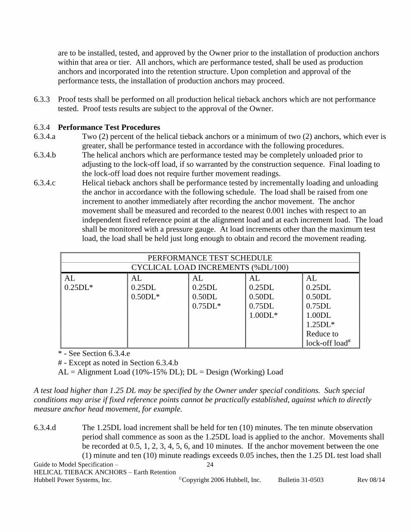
6.3.4 Performance Test Procedures
6.3.4.a Two (2) percent of the helical tieback anchors or a minimum of two (2) anchors, which ever is
greater, shall be performance tested in accordance with the following procedures.
6.3.4.b The helical anchors which are performance tested may be completely unloaded prior to
adjusting to the lock-off load, if so warranted by the construction sequence. Final loading to
the lock-off load does not require further movement readings.
6.3.4.c Helical tieback anchors shall be performance tested by incrementally loading and unloading
the anchor in accordance with the following schedule. The load shall be raised from one
increment to another immediately after recording the anchor movement. The anchor
movement shall be measured and recorded to the nearest 0.001 inches with respect to an
independent fixed reference point at the alignment load and at each increment load. The load
shall be monitored with a pressure gauge. At load increments other than the maximum test
load, the load shall be held just long enough to obtain and record the movement reading.
PERFORMANCE TEST SCHEDULE
CYCLICAL LOAD INCREMENTS (%DL/100)
AL AL AL AL AL
0.25DL* 0.25DL 0.25DL 0.25DL 0.25DL
0.50DL* 0.50DL 0.50DL 0.50DL
0.75DL* 0.75DL 0.75DL
1.00DL* 1.00DL
1.25DL*
Reduce to
lock-off load#
* - See Section 6.3.4.e
# - Except as noted in Section 6.3.4.b
AL = Alignment Load (10%-15% DL); DL = Design (Working) Load
A test load higher than 1.25 DL may be specified by the Owner under special conditions. Such special
conditions may arise if fixed reference points cannot be practically established, against which to directly
measure anchor head movement, for example.
6.3.4.d The 1.25DL load increment shall be held for ten (10) minutes. The ten minute observation
period shall commence as soon as the 1.25DL load is applied to the anchor. Movements shall
be recorded at 0.5, 1, 2, 3, 4, 5, 6, and 10 minutes. If the anchor movement between the one
(1) minute and ten (10) minute readings exceeds 0.05 inches, then the 1.25 DL test load shall

Guide to Model Specification –
HELICAL TIEBACK ANCHORS – Earth Retention
Hubbell Power Systems, Inc. ©Copyright 2006 Hubbell, Inc. Bulletin 31-0503 Rev 08/14
25
be maintained for an additional 20 minutes. Movements shall be recorded at 15, 20, 25, and
30 minutes. If the acceptance criteria given in Section 6.4.1 is not satisfied, then the anchor
test shall be continued for an additional 30 minutes. Movements shall be recorded at 45 and
60 minutes. If the acceptance criteria is not satisfied after this extended observation period,
then the contractor shall exercise one of the options as referenced in Section 6.4.2.
6.3.4.e The Contractor shall plot the helical anchor movement versus load for each load increment
marked with an asterisk (*) in the performance test schedule and plot the residual movement
at each alignment load versus the highest previously applied load.
6.3.4.f Throughout the 1.25DL observation period, the load shall be held constant by adjusting the
hydraulic pressure. Care must be taken so as not to exceed the 1.25DL test load.
6.3.5 Proof Test Procedures
6.3.5.a All anchors which are not performance tested shall be proof tested.
6.3.5.b Anchors which are proof tested may be completely unloaded prior to adjusting to the lock-off
load, if so warranted by the construction sequence. Final loading to the lock-off load does not
require further movement readings.
6.3.5.c The proof test shall be performed by incrementally loading the helical anchor in accordance
with the following schedule. The load shall be raised from one increment to another after an
observation period. The anchor movement shall be measured and recorded to the nearest
0.001 inches with respect to an independent fixed reference point at the alignment load and at
each increment load. The load shall be monitored with a pressure gauge. At load increments
other than the maximum test load, the load shall be held for a period not to exceed two (2)
minutes. The two minute observation period shall begin when the pump begins to load the
anchor to the next load increment. Movement readings shall be taken at the end of the two
minute observation period.
PROOF TEST SCHEDULE
LOAD TEST SCHEDULE (%DL/100) OBSERVATION PERIOD (MIN.)
AL 0.0
0.25DL 2.0
0.50DL 2.0
0.75DL 2.0
1.00DL 2.0
1.25DL* 5.0
Reduce to lock-off load#
* - see Section 6.3.5.e
# - except as noted in Section 6.3.5.b
AL = Alignment Load (10%-15% DL)
DL = Design (Working) Load
6.3.5.d The 1.25DL test load shall be maintained for five (5) minutes. This five minute observation
period shall commence as soon as the 1.25DL is applied to the anchor. Movement readings
shall be recorded at 0.5, 1, 2, 3, 4, and 5 minutes. If the movement between the 0.5 and 5

Guide to Model Specification –
HELICAL TIEBACK ANCHORS – Earth Retention
Hubbell Power Systems, Inc. ©Copyright 2006 Hubbell, Inc. Bulletin 31-0503 Rev 08/14
26
minute reading exceeds 0.05 inches, then the 1.25DL test load shall be maintained for an
additional five (5) minutes. Movement readings shall be recorded at 6 and 10 minutes. If the
acceptance criteria given in Section 6.4.1 is not satisfied, then the anchor test shall be
continued for an additional twenty (20) minutes. Movement readings shall be recorded at 15,
20, 25, and 30 minutes. If the acceptance criteria is not satisfied after this extended
observation period, then the contractor shall exercise one of the options as referenced in
Section 6.4.2.
6.3.5.e The Contractor shall plot the helical anchor movement vs. load for each load increment in the
proof test.
6.3.5.f Throughout the 1.25DL observation period, the load shall be held constant by adjusting the
hydraulic pressure. Care must be taken so as not to exceed the 1.25DL test load.
6.4 Acceptance Criteria
6.4.1 The net movement for the performance and proof tests shall not exceed 0.10 inches during the final
log cycle of time (examples, 3-min. to 30-min. for performance tests; 1-min. to 10-min. for proof
tests).
6.4.2 If the above criteria is exceeded, then the test shall be continued for an extended period of time as
defined in Section 6.3.4.d for the performance test and in Section 6.3.5.d for the proof test. If the
final log cycle of time movement at the end of the extended observation period exceeds 0.10 then the
contractor shall have the following options:
6.4.2.a Extend the observation period for an additional 60 minutes for the performance test with
movement readings taken at 80, 90, 100, and 120 minutes. Extend the observation period for
an additional 30 minutes if the proof test is involved with movement readings taken at 45 and
60 minutes. The net movement shall not exceed 0.10 inches during the final log cycle of
time.
6.4.2.b Install the helical anchor deeper so as to increase its average installation torque, provided that
the maximum torque capacity of the anchor and the maximum length constraint, is not
exceeded. This anchor shall be proof tested.
6.4.2.c Remove the helical anchor and reinstall an anchor with larger diameter and/or additional
helices. If this anchor is reinstalled at the same location, then the last helix of this reinstalled
anchor shall penetrate at least five (5'-0) feet beyond the length of the original anchor,
provided the maximum length constraint is not exceeded. This anchor shall be proof tested.
6.4.2.d Reduce the design load of the helical anchor. This anchor shall be performance tested at the
reduced design load. This option will require one or two additional anchors be installed
adjacent to this reduced design load anchor. The number of additional anchors to be installed
is a function of the reduced design load. Adjacent anchor(s) shall be installed at least three
diameters, based on the largest helix, away from the reduced design load anchor. Design
loads on adjacent anchor(s) shall be adjusted accordingly based on the revised horizontal
spacing.

Guide to Model Specification –
HELICAL TIEBACK ANCHORS – Earth Retention
Hubbell Power Systems, Inc. ©Copyright 2006 Hubbell, Inc. Bulletin 31-0503 Rev 08/14
27
7 MEASUREMENT AND PAYMENT
Helical tieback anchor work can be paid for in different ways, reflecting the relative risk to be accepted by
the Owner and the Contractor. However, the following items are common and standard.
QUANTITY DESCRIPTION UNIT
1 Mobilization/Demobilization Lump sum
As required Conduct pre-production test
anchor program of declared
scope
Lump sum
As required Performance Test Production
Helical Anchors
Per anchor
- Obstructions Per hour or Force
Account
As required Helical Anchor Installation As below
Per Unit Length: Helical tieback anchors meeting the design capacity shall be paid for per lineal foot
below grade.
Per Helical Anchor: Helical tieback anchors meeting the design capacity shall be paid for on a “per
anchor” basis (no allowance for changes in length relative to that originally bid).
Per Helical Anchor with Add/Deduct: Helical tieback anchors meeting the design capacity shall be paid
for on a “per anchor” basis, with a predetermined length, and an add/deduct amount per lineal foot to
accommodate field changes.
Lump Sum: The whole helical tieback anchor project shall be paid for on a “lump sum” basis (no
allowance for changes due to additional anchor length relative to that originally bid).
END OF SPECIFICATION

Guide to Model Specification –
HELICAL TIEBACK ANCHORS – Earth Retention
Hubbell Power Systems, Inc. ©Copyright 2006 Hubbell, Inc. Bulletin 31-0503 Rev 08/14
28
APPENDIX
TABLE-A
CHANCE Civil Construction
MECHANICAL STRENGTH RATINGS – Type SS HELICAL ANCHORS
RATING TYPE CENTRAL STEEL SHAFT PRODUCT FAMILY
SS125
1-1/4”
RCS
SS5
1-1/2”
RCS
SS150
1-1/2”
RCS
SS175
1-3/4”
RCS
SS200
2”
RCS
SS225
2-1/4”
RCS
Torque Strength
Rating (ft-lb) 4,000 5,700 7,000 10,500 16,000 23,000
Ultimate Strength Per
Helix (kip)
(Tension/Compression)
*30 *40 *40 *50 60 60
Tension Capacity
Limit1 (kip)
40 55 70 #105 #160 #230
Ultimate Tension
Strength2 (kip) 60 70 70 100 150 200
* For 14” Dia. 3/8” Thick Helix Plates, Reduce the Ultimate Capacity by 20%
1 - Based on torque rating – Tension Capacity Limit = Torque Rating x Kt; “Default” Kt for Type SS = 10
2 – Based on mechanical strength of coupling
# - Limited by mechanical strength of coupling bolt
Actual installed capacities are dependent on site specific soil conditions.

Guide to Model Specification –
HELICAL TIEBACK ANCHORS – Earth Retention
Hubbell Power Systems, Inc. ©Copyright 2006 Hubbell, Inc. Bulletin 31-0503 Rev 08/14
29
APPENDIX
TABLE-B
GUIDANCE OF GROUND AGGRESSIVENESS CLASSIFICATION
Soil tests may be performed to measure the aggressiveness of the soil environment, especially if field
observations indicate corrosion of existing structures. The most common and simplest tests are for electrical
resistivity, pH, chloride, and sulfates. The designation for these tests and the critical values defining whether
an aggressive soil environment exists, are as shown below. Per FHWA-RD-89-198, the ground is considered
aggressive if any one of these indicators shows critical values.
Property Test Designation Critical Values
Resistivity ASTM G 57
AASHTO T-288
below 2,000 ohm-cm
pH ASTM G 51
AASHTO T-289
below 5
Sulfate ASTM D 516M
ASTM D 4327
above 200 ppm
Chloride ASTM D 512
ASTM D 4327
AASHTO T-291
above 100 ppm
Organic Content AASHTO T-267 1% max