Guide to Closing and Conditioning Ventilated Crawlspaces · PDF fileGuide to Closing and...
48
Guide to Closing and Conditioning Ventilated Crawlspaces Bruce Dickson IBACOS, Inc. January 2013
Transcript of Guide to Closing and Conditioning Ventilated Crawlspaces · PDF fileGuide to Closing and...
Guide to Closing and Conditioning Ventilated Crawlspaces Bruce Dickson IBACOS, Inc.
January 2013
NOTICE
This report was prepared as an account of work sponsored by an agency of the United States government. Neither the United States government nor any agency thereof, nor any of their employees, subcontractors, or affiliated partners makes any warranty, express or implied, or assumes any legal liability or responsibility for the accuracy, completeness, or usefulness of any information, apparatus, product, or process disclosed, or represents that its use would not infringe privately owned rights. Reference herein to any specific commercial product, process, or service by trade name, trademark, manufacturer, or otherwise does not necessarily constitute or imply its endorsement, recommendation, or favoring by the United States government or any agency thereof. The views and opinions of authors expressed herein do not necessarily state or reflect those of the United States government or any agency thereof.
Available electronically at http://www.osti.gov/bridge
Available for a processing fee to U.S. Department of Energy and its contractors, in paper, from:
U.S. Department of Energy Office of Scientific and Technical Information
P.O. Box 62 Oak Ridge, TN 37831-0062
phone: 865.576.8401 fax: 865.576.5728
email: mailto:[email protected]
Available for sale to the public, in paper, from: U.S. Department of Commerce
National Technical Information Service 5285 Port Royal Road Springfield, VA 22161 phone: 800.553.6847
fax: 703.605.6900 email: [email protected]
online ordering: http://www.ntis.gov/ordering.htm
Printed on paper containing at least 50% wastepaper, including 20% postconsumer waste
iii
Guide to Closing and Conditioning Ventilated Crawlspaces
Prepared for:
The National Renewable Energy Laboratory
On behalf of the U.S. Department of Energy’s Building America Program
Office of Energy Efficiency and Renewable Energy
15013 Denver West Parkway
Golden, CO 80401
NREL Contract No. DE-AC36-08GO28308
Prepared by:
Bruce Dickson
IBACOS, Inc.
2214 Liberty Avenue
Pittsburgh, Pennsylvania 15222
NREL Technical Monitor: Michael Gestwick
Prepared under Subcontract No. KNDJ-0-40341-01
January 2013

iv
[This page left blank]
v
Contents List of Figures ........................................................................................................................................... vii Definitions ................................................................................................................................................. viii Executive Summary .................................................................................................................................... 1 1 Basic Concepts: Moisture Transport ................................................................................................. 4
1.1 Where Does the Moisture in a Crawlspace Come From? ....................................................4 2 Evaluation .............................................................................................................................................. 6
2.1 Immediate Health and Safety Issues ....................................................................................7 2.1.1 Electrical Inspection .................................................................................................7 2.1.2 Mechanical Systems/Carbon Monoxide ..................................................................7 2.1.3 Mold/Framing ..........................................................................................................7 2.1.4 Asbestos ...................................................................................................................7 2.1.5 Hazardous Materials Storage ...................................................................................8 2.1.6 Radon .......................................................................................................................8
2.2 Exterior Moisture Sources ...................................................................................................8 2.2.1 Roof Drainage Away from the House .....................................................................8 2.2.2 Grading Around the House ......................................................................................8 2.2.3 Sprinklers .................................................................................................................8 2.2.4 Foundation Waterproofing and Drainage ................................................................8 2.2.5 Foundation Vents .....................................................................................................8 2.2.6 Access Door .............................................................................................................9
2.3 Interior Moisture Sources ....................................................................................................9 2.3.1 Standing Water on the Floor ....................................................................................9 2.3.2 Leaking Drains or Supply Plumbing........................................................................9 2.3.3 Mechanical System Condensate Drain ....................................................................9 2.3.4 Vent Openings .........................................................................................................9 2.3.5 Sump Pump ..............................................................................................................9 2.3.6 Drain Pipes .............................................................................................................10
2.4 Other Contaminants ...........................................................................................................10 2.4.1 Feces, Carcasses, and Other Animal Waste ...........................................................10 2.4.2 Animal Infestation .................................................................................................10 2.4.3 Pest Control ............................................................................................................10
2.5 Thermal ..............................................................................................................................10 2.5.1 Insulation Strategy .................................................................................................10 2.5.2 Space Conditioning ................................................................................................10
3 Preparation and Retrofit .................................................................................................................... 12 3.1 Exterior Moisture ...............................................................................................................12 3.2 Exterior Waterproofing and Drainage ...............................................................................12 3.3 Crawlspace Access .............................................................................................................13 3.4 Prepare the Crawlspace Floor ............................................................................................15 3.5 Mechanical Systems...........................................................................................................16
3.5.1 Combustion Safety .................................................................................................16 3.5.2 Ductwork................................................................................................................18 3.5.3 Space Conditioning ................................................................................................18 3.5.4 Air Conditioning Condensate Drainage .................................................................18 3.5.5 Dehumidifiers ........................................................................................................19
vi
3.6 Band Joist Insulation ..........................................................................................................19 3.7 Air Sealing .........................................................................................................................20
3.7.1 Foundation Vent Sealing........................................................................................20 3.7.2 Penetrations/Holes .................................................................................................21
3.8 Crawlspace Floor ...............................................................................................................22 3.8.1 Poly Vapor Barrier .................................................................................................22 3.8.2 Sump Pump Crock Pit and Floor Drain .................................................................25
3.9 Wall Insulation ...................................................................................................................26 3.10 Final Steps ..............................................................................................................28
3.10.1 Service Areas .........................................................................................................28 3.10.2 Water Sensing Alarm .............................................................................................28 3.10.3 Vapor Barrier Inspection ........................................................................................29 3.10.4 Additional Monitoring Equipment .........................................................................29
4 Homeowner Education ....................................................................................................................... 31 4.1 Warning Sign .....................................................................................................................31 4.2 Trim Materials ...................................................................................................................31
Glossary ..................................................................................................................................................... 32 References ................................................................................................................................................. 33 Appendix A: Work Plans and Checklists ................................................................................................ 36 Appendix B: Material Specifications ....................................................................................................... 39
vii
List of Figures Figure 1. Types of crawlspace foundation systems applicable to this guideline ................................ 3 Figure 2. Capillary action ........................................................................................................................... 4 Figure 3. Bulk moisture transport ............................................................................................................. 4 Figure 4. Air transport ................................................................................................................................ 5 Figure 5. Vapor diffusion ............................................................................................................................ 5 Figure 6. Water management to keep bulk water away from the crawlspace .................................... 13 Figure 7. Exterior access door ................................................................................................................ 14 Figure 8. Interior access door .................................................................................................................. 14 Figure 9. Crawlspace exterior details ..................................................................................................... 15 Figure 10. Crawlspace floor ..................................................................................................................... 16 Figure 11. Direct vent furnace with combustion air intake and exhaust pipes directly
to outdoors .......................................................................................................................................... 17 Figure 12. Seal and support duct system ............................................................................................... 18 Figure 13. Supply air diffuser .................................................................................................................. 19 Figure 14. Underside of passive vent in floor structure ....................................................................... 19 Figure 15. Foam sealant at band joist insulation and penetrations..................................................... 20 Figure 16. Band joist insulation and air sealing .................................................................................... 20 Figure 17. Measure existing foundation vent openings ........................................................................ 21 Figure 18. Cut rigid foam inserts to fit over the existing foundation vents ........................................ 22 Figure 19. Use spray foam to seal the edges of the foam inserts ....................................................... 22 Figure 20. Clean and grade the crawlspace ........................................................................................... 23 Figure 21. Lap the vapor barrier, and seal the connection ................................................................... 24 Figure 22. Apply poly vapor barrier, and lap and seal the seams........................................................ 24 Figure 23. Use mesh tape to seal the vapor barrier to the interior surface of the
foundation walls 4 in. below the top of the wall .............................................................................. 25 Figure 24. Embed the mesh tape with mastic to complete the seal .................................................... 25 Figure 25. Crock pit lid sealing ................................................................................................................ 26 Figure 26. Low-point floor drain sealing ................................................................................................. 26 Figure 27. U.S.climate zone map ............................................................................................................. 27 Figure 28. Install rigid insulation to the crawlspace walls, allowing a 3-in. termite strip
if needed .............................................................................................................................................. 27 Figure 29. Vent area insulation ................................................................................................................ 28 Figure 30. Vent area sealing .................................................................................................................... 28 Figure 31. Crawlspace interior details .................................................................................................... 30 Figure 32. Example of a warning sign posted at an access entryway ................................................ 31 Unless otherwise noted, all figures were created by IBACOS.
viii
Definitions
ASTM American Society for Testing and Materials
BPI Building Performance Institute
Btu British thermal unit
CAZ Combustion air zone
cfm Cubic feet per minute
CMU Concrete masonry unit
ft2 Square foot
ft3 Cubic foot
h Hour
ICC-ES International Code Council Evaluation Service
IECC International Energy Conservation Code®
IFGC International Fuel Gas Code
IMC International Mechanical Code
IRC International Residential Code
L Liter
m2 Square meter
NFPA National Fire Protection Association
s Second
1
Executive Summary
This how-to guide is designed to explain the issues and concerns with conventional ventilated crawlspaces and to outline prescriptive measures for improvements that will create healthier and more durable spaces.
The methods described in this guideline are not the only acceptable ways to treat a crawlspace but represent a proven strategy that works in many areas of the United States. The designs discussed here may or may not meet the local building codes, so they will need to be researched locally before beginning the project.
Crawlspaces in the United States typically are constructed of hollow masonry block or poured concrete stem walls. In general, these foundations are equipped with permanent vents to the outdoors that are intended to furnish cross-ventilation to prevent moisture in the space. Until recently, houses built over vented crawlspaces have been constructed with little or no regard to moisture-causing sources that can contribute to long-term structural damage and pose health hazards. The interior and exterior detailing of many construction components needs to be evaluated and installed correctly to combat unwanted moisture within a crawlspace. Past research has shown that a conventionally vented crawlspace that has been converted into an unvented and conditioned space tends to operate similarly to houses with basements, with several benefits for the homeowner (BSC 2004):
• Energy savings
• Comfort
• Moisture control
• Long-term durability
• Healthier air quality.
Research has shown that vented crawlspaces located in mixed or hot-humid climates tend to increase the moisture level within the space instead of keeping it drier. This increased moisture then condenses on the colder wood surfaces of the floor framing, promoting fungal growth and wood damage. Vented crawlspaces also have the potential to rob energy savings from the living spaces of the home if the appropriate insulation strategy has not been followed correctly. Retrofitting a vented crawlspace into an unvented, insulated, sealed, and dry space requires more than just sealing off the vent openings. Not considering other details within the crawlspace and simply sealing the vents could make the situation worse, increasing the levels of moisture and potentially creating a deadly situation if naturally ventilated types of combustion equipment are located in the crawlspace. Depending on the conditions, it might be best to implement the closed crawlspace strategy slowly to minimize the effects of materials rapidly drying out. Rapid and excessive drying can potentially cause cosmetic damage to wood-based finish products in the living area of the home. Conversely, swollen and cupped hardwood flooring may flatten during the drying process.

2
The following groups should use this how-to guide as a tool to help them properly implement strategies to convert a traditional crawlspace with open foundation vents and poor design and construction into an unvented, insulated, and conditioned space:
• Builders
• Home remodelers
• Insulation trades
• Mechanical trades
• Homeowners (as a reference guide to understand the work being performed by others).
This guideline recommends widespread use of rigid foam boards as the insulation strategy for walls and band joist areas. According to Advanced Energy (2005):
Foam plastic insulation receives special scrutiny in residential building codes because some foam insulations have the potential to release toxic or flammable gases when heated, or they can accelerate the spread of fire if they ignite. To reduce these risks, most codes require a thermal barrier (typically ½-in. [13-mm] gypsum board or equivalent) or an ignition barrier (typically ⅜-in. [10-mm] gypsum board or equivalent) over foam insulation. However, several foam insulation products have been designed and tested to reduce or eliminate those risks. Duct products can be installed without a thermal barrier or ignition barrier with the appropriate documentation.
Houses located in flood zones may be required to have flood vents. Flood vents are openings in a foundation wall that automatically allow the free passage of flood water into and out of a foundation to equalize hydrostatic forces on the foundation walls. When required in a closed crawlspace, choose a flood vent model that reduces standby air leakage as much as possible. The Federal Emergency Management Agency and the National Flood Insurance Program specify the design requirements for flood vents as well as the guidelines for where they must be implemented. The 2000 (and later) International Codes meet these requirements. To determine if a property is located in a Special Flood Hazard Area that would require flood vent installation, contact your local building inspections department or governing authority.
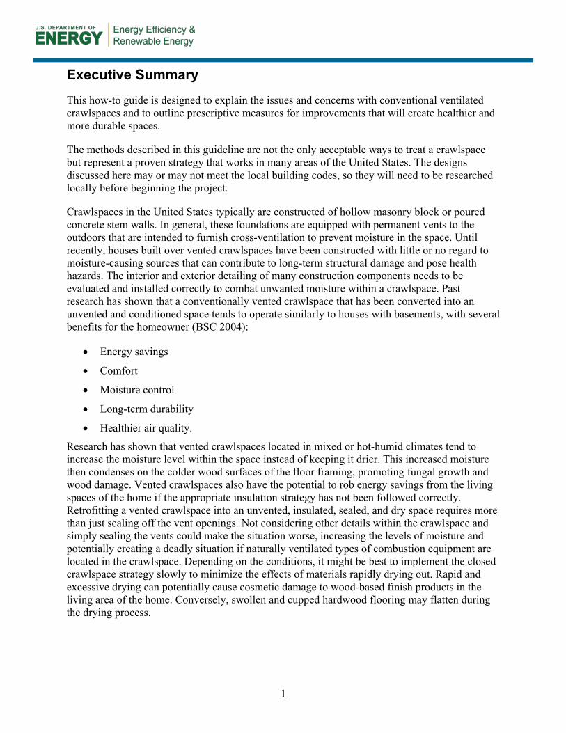
This guide is intended to apply to crawlspace foundations that are constructed of solid concrete or concrete masonry units (CMU) with a continuous brick cap or bond beam that minimizes the potential for moisture movement from the ground through the masonry cores toward the wood floor structure (see Figure 1).
3
Figure 1. Types of crawlspace foundation systems applicable to this guideline
4
1 Basic Concepts: Moisture Transport
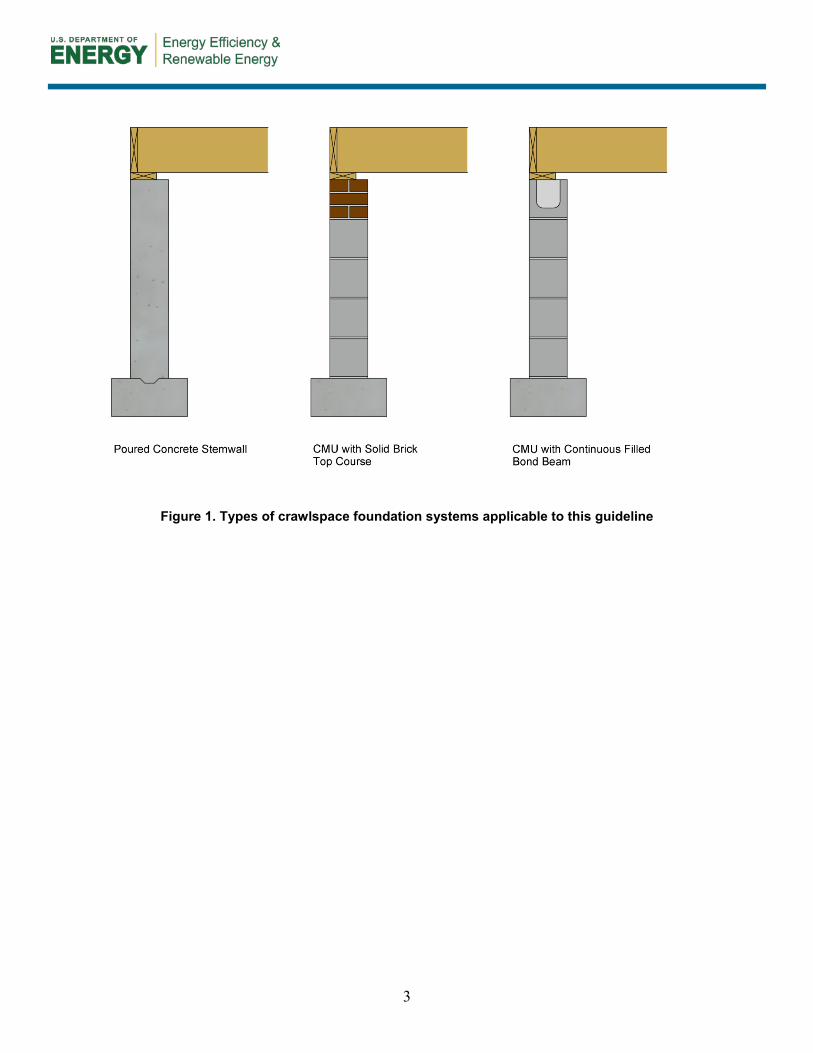
1.1 Where Does the Moisture in a Crawlspace Come From? There are four primary modes of moisture migration into a home: capillary action, bulk moisture transport, air transport, and vapor diffusion. Each of these modes, described in the following list, must be controlled to preserve comfort, health, and building durability.
1. Capillary action (see Figure 2):
• Water wicks through porous materials or through small cracks.
• Primary sources are rain and groundwater.
Figure 2. Capillary action
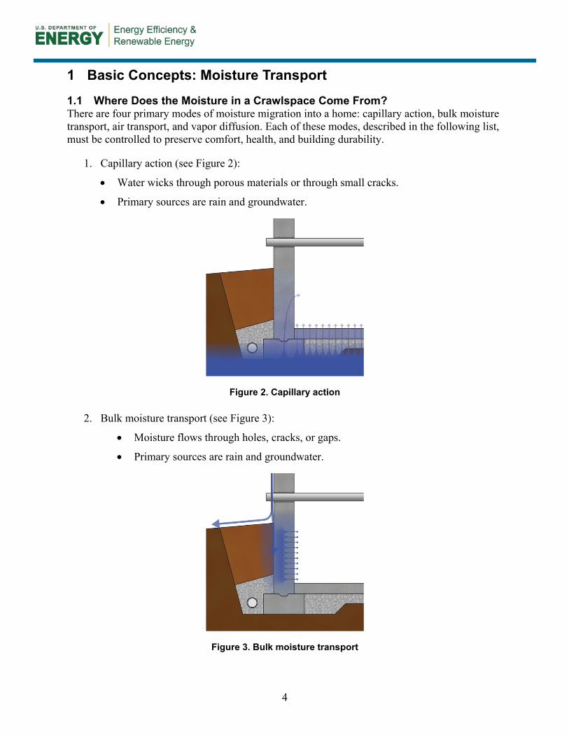
2. Bulk moisture transport (see Figure 3):
• Moisture flows through holes, cracks, or gaps.
• Primary sources are rain and groundwater.
Figure 3. Bulk moisture transport
5
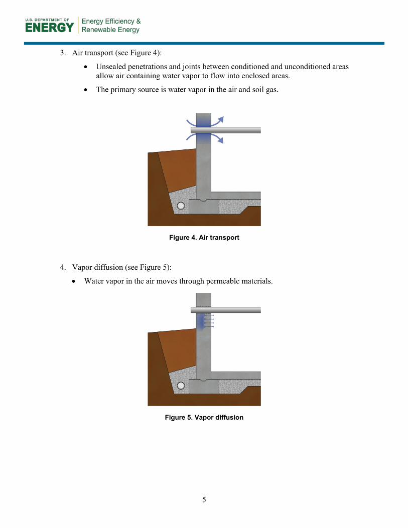
3. Air transport (see Figure 4):
• Unsealed penetrations and joints between conditioned and unconditioned areas allow air containing water vapor to flow into enclosed areas.
• The primary source is water vapor in the air and soil gas.
Figure 4. Air transport
4. Vapor diffusion (see Figure 5):
• Water vapor in the air moves through permeable materials.
Figure 5. Vapor diffusion
6
2 Evaluation
The first step in developing a plan for a crawlspace conversion is to perform a thorough evaluation of both the exterior and interior conditions. This inspection must be based on federal, state, and local regulations and carried out by a licensed or certified contractor. The following areas and specific details must be attended to before starting the sealing and insulating of any crawlspace:
• Immediate health and safety issues
o Electrical
o Mechanical systems/carbon monoxide
o Mold/framing
o Asbestos
o Hazardous materials storage
o Radon
• Exterior moisture sources
o Roof drainage away from the house
o Grading around the house
o Sprinklers
o Foundation waterproofing and drainage
o Access door
• Interior moisture sources
o Leaking drains or supply plumbing
o Condensate drain
o Standing water on the floor
o Crawlspace floor
o Vent openings
o Sump pump crock pit
o Water softener discharge
• Other contaminants
o Feces, carcasses, and other animal waste
o Animal infestation
o Termites and carpenter ants
7
• Thermal
o Insulation strategy
o Space conditioning.
2.1 Immediate Health and Safety Issues Electrical Inspection 2.1.1
Assessing the current electrical system within the crawlspace is one of the first steps to take. A qualified electrician might need to be consulted if there is exposed or damaged wiring within the crawlspace. If there is a risk of shock or electrocution from faulty wiring, postpone the inspection of the interior systems until any issues have been resolved and the space is safe.
Mechanical Systems/Carbon Monoxide 2.1.2Establish the type of space conditioning equipment and water heaters. If fuel-fired combustion appliances reside in the crawlspace, it is important to determine their venting and combustion air sources. These life-safety strategies are a critical first step in the overall renovation efforts of the crawlspace. If natural draft-vented appliances that depend on combustion air from the open vents in the foundation are present, equipment upgrades and replacement or alterations to the makeup air methods will be necessary. The best strategy is to replace natural draft-vented appliances with sealed combustion, direct vent furnaces or all-electric heat pumps. The direct vent gas furnaces draw combustion air directly from outside through piping to the unit. All combustion by-products are vented through sealed piping to the outdoors, minimizing the possibility of any carbon monoxide spillage. Verify that a carbon monoxide detector is installed and operational in the crawlspace.
If there are any gas line regulators within the crawlspace, they will need to be moved so they vent to the outdoors.
Mold/Framing 2.1.3Finding some traces of mold or mildew is common in a poorly detailed and ventilated crawlspace. The floor deck and all framing in the crawlspace are vulnerable to some level of fungal attack if moisture levels within the crawlspace go unchecked. Once high levels of moisture are present, moisture will tend to condense on the cooler surfaces of the wood framing and floor deck. These areas are easy to observe and are an indicator of high moisture content. Any surface mold or fungal growth will require a certified mold remediation expert to conduct an inspection and determine an appropriate remediation protocol to clean all the components before work can proceed. Structural repairs to framing components might be necessary if there is extensive damage or wood rot.
Asbestos 2.1.4Exposure to asbestos increases a person’s risk of developing lung disease. Old crawlspaces might have asbestos-based insulation wraps on ductwork and plumbing pipes. If discovered, a certified asbestos abatement firm will have to be contracted to inspect and determine the best treatment strategy for the particular situation. General movement and unintentional contact with asbestos-based products can stir the fibers, which then become airborne within the confined space, posing a health risk to workers.
8
Hazardous Materials Storage 2.1.5Completely remove and properly dispose of all hazardous materials if any hazardous-type material has been stored in the crawlspace (e.g., creosote-treated lumber or pesticides).
Radon 2.1.6In areas where radon is a risk or where the local residential code requires control of radon or other soil gases, houses with closed crawlspace foundations must be tested and monitored. If necessary, an approved mitigation system must be installed. The U.S. Environmental Protection Agency (EPA) and the Surgeon General recommend testing all homes for radon.
Installing a passive radon mitigation system before undertaking all sealing work could be necessary in radon-prone areas. After the crawlspace is closed and sealed, final testing for radon can take place. Converting the passive system to an active system is easily accomplished if readings exceed the EPA’s acceptable levels.
2.2 Exterior Moisture Sources Roof Drainage Away from the House 2.2.1
Inspect the roof’s bulk water discharge strategy, including all gutters and downspouts, to ensure bulk water runoff is not allowed to collect next to or near the foundation. Downspouts should discharge directly into drains that are directed to a storm sewer system, retention pond, daylighting if the land topography permits, or yard bubblers that are a minimum of 10 ft away from the foundation.
Grading Around the House 2.2.2Evaluate the grading around the perimeter of the house. Ideally, the ground slopes a minimum of 5% away from the foundation walls for at least the first 10 ft to direct groundwater away from the structure. If proper slope away from the foundation cannot be established because of the home’s elevation and surrounding grade, a surface drainage system (“grade gutter”) should be installed. This system collects water and diverts it away from the foundation.
Before beginning any excavation work, make sure to identify any underground utilities that enter the house, and notify the respective utility companies as required.
Sprinklers 2.2.3Turn on all sprinklers installed near the foundation to observe their flow pattern. The sprinklers must be positioned so they do not subject the foundation or its immediate vicinity to water.
Foundation Waterproofing and Drainage 2.2.4Implementing foundation waterproofing and a perimeter drain strategy on the exterior walls will be required on exceptionally problematic sites. Such sites typically have high groundwater or water flow against the foundation that cannot be remediated in any other way.
Foundation Vents 2.2.5The foundation vents can be another source of bulk water entry. Make sure that they are not too low in relation to the exterior grade. If the vents fall near or below grade, they will need to be filled in with block, brick, or concrete and sealed to prevent water entry.
9
Access Door 2.2.6Inspect the general location and overall weather seal of the access door. The access door should be located high enough off of grade to prevent groundwater runoff and snowmelt from entering the crawlspace. If the door is located too low and there is not enough clearance to adjust the entry height, remove the door, seal the opening, and install a new entry at a different location on the exterior that will accommodate the clearance. If no suitable location meets these criteria, cutting an access way through the floor system within the house will be required.
2.3 Interior Moisture Sources Standing Water on the Floor 2.3.1
Any recognizable standing water must be eliminated and the source of the water identified and repaired to prevent a reoccurrence that would raise the moisture levels within the space. Typically, standing water indicates a leaking pipe from above or groundwater entering the space from outside the building or under the floor.
Leaking Drains or Supply Plumbing 2.3.2Conduct a thorough inspection of all drains and supply plumbing located within the crawlspace to make sure no leaks are adding moisture to the space.
Mechanical System Condensate Drain 2.3.3Evaluate the entire length of the condensate drain from the air handler to the discharge point. Because of the potentially corrosive discharge from sealed combustion furnaces and air conditioners, condensate drains must be installed as required by local jurisdictions. They must be properly supported and routed directly to a sealed sump crock lid, a floor drain fitting, or a sanitary sewer.
In addition to the primary drain and as a safety precaution if the primary drain fails, an auxiliary drain pan with a separate drain beneath any cooling or evaporator coil is recommended to prevent condensate from flooding the crawlspace. Inspect the current condition of the crawlspace floor because it is a critical factor in directing any surface water toward collector drains and the sump. It also minimizes moisture movement from the soil into the crawlspace environment. Poor sealing practices of the polyethylene vapor barrier allow ground moisture to infiltrate through gaps or open seams in the barrier, increasing the relative humidity of the crawlspace. Grading the base to a minimum 3% slope toward low-spot collector drains that can move water directly to the sump is necessary to eliminate ground moisture from seeping into the space.
Vent Openings 2.3.4All intentional, operable, or fixed foundation vents will need to be sealed to prevent warm, moisture-laden air from being drawn into the crawlspace. If vents are too low and likely to pose bulk water intrusion into the crawlspace, they will need to be sealed with concrete block, brick, concrete, or glass block windows to prevent water entry.
Sump Pump 2.3.5Inspect all sump pump crock pits installed in the crawlspace, looking at the detailing of their lids and any drain pipe penetrations. Missing lids and an absence of sealing will allow moisture to enter and increase the relative humidity of the crawlspace. The 2009 IRC states the following in Section R405.2.3, Drainage System (IRC 2009a, p. 107):
10
In other than Group I soils, a sump shall be provided to drain the porous layer and footings. The sump shall be at least 24 inches (610 mm) in diameter or 20 inches square (0.01129 m2), shall extend at least 24 inches (610 mm) below the bottom of the basement floor and shall be capable of positive gravity or mechanical drainage to remove any accumulated water. The drainage system should discharge into an approved sewer system or to daylight.
In areas with high water tables, installing a battery backup system to the pump is recommended to aid in drainage during power outages.
Drain Pipes 2.3.6To prevent any water backups through drain pipes, Advanced Energy recommends the following (Advanced Energy 2012, p. 12):
Use a backflow valve in crawlspace drains and a check valve in sump pump out-flow pipes to prevent reverse flow of outside water into the crawlspace and to reduce the chance of vermin entry. Floor drains with p-traps that connect to the whole house plumbing waste drain or to a municipal sewer system may allow entry or sewer gases if (when) the trap dries out and pose a risk of sewage backup.
2.4 Other Contaminants Feces, Carcasses, and Other Animal Waste 2.4.1
Old existing crawlspaces, if left unattended, can contain large amounts of animal droppings or carcasses of animals that have found a way into the crawlspace and died. Be prepared for this possibility, and have the means to conduct a thorough cleanup before proceeding.
Animal Infestation 2.4.2In some cases, crawlspaces that have been left unattended or neglected can harbor wild animals. Recognizing the exterior details that allow entry and exit and other activity will help prepare the inspector. Depending on the severity, the local animal control agency might need to assist in removing any unwanted animals.
Pest Control 2.4.3Termites and carpenter ants are known to thrive in dark, damp places that have a readily available food source nearby. Inspecting the foundation walls and framing for signs of these pests is required before moving forward. Any observed signs will then require a more in-depth inspection and treatment by a pest control professional.
2.5 Thermal Insulation Strategy 2.5.1
The current insulation levels, location, and integrity will need to be assessed to determine the appropriate strategy for the climatic region. Existing fiberglass batt insulation in the floor system and draped over the foundation walls should be removed and discarded. A good work plan will include a thorough specification and implementation strategy for thermal insulation.
Space Conditioning 2.5.2Crawlspaces must always have a drying mechanism. One of the most effective ways is to condition the crawlspace by bringing in a reduced amount of conditioned air from the
11
mechanical system to temper the space as if it were part of the home. A supply and return air strategy must be included to semicondition the crawlspace.
In some areas of the country that do not have air conditioning or if local requirements will not allow band joist insulation, it might be necessary to install a permanent dehumidification system in the crawlspace to maintain the 30%–50% humidity levels within the space.
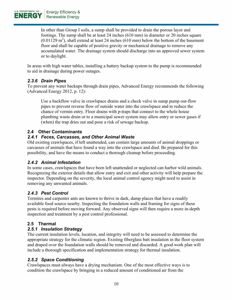
Table 1 summarizes the conditions that will necessitate stopping all work on the crawlspace project. Once these problems have been solved, renovation work can continue.
Table 1. Critical Checklist
12
3 Preparation and Retrofit
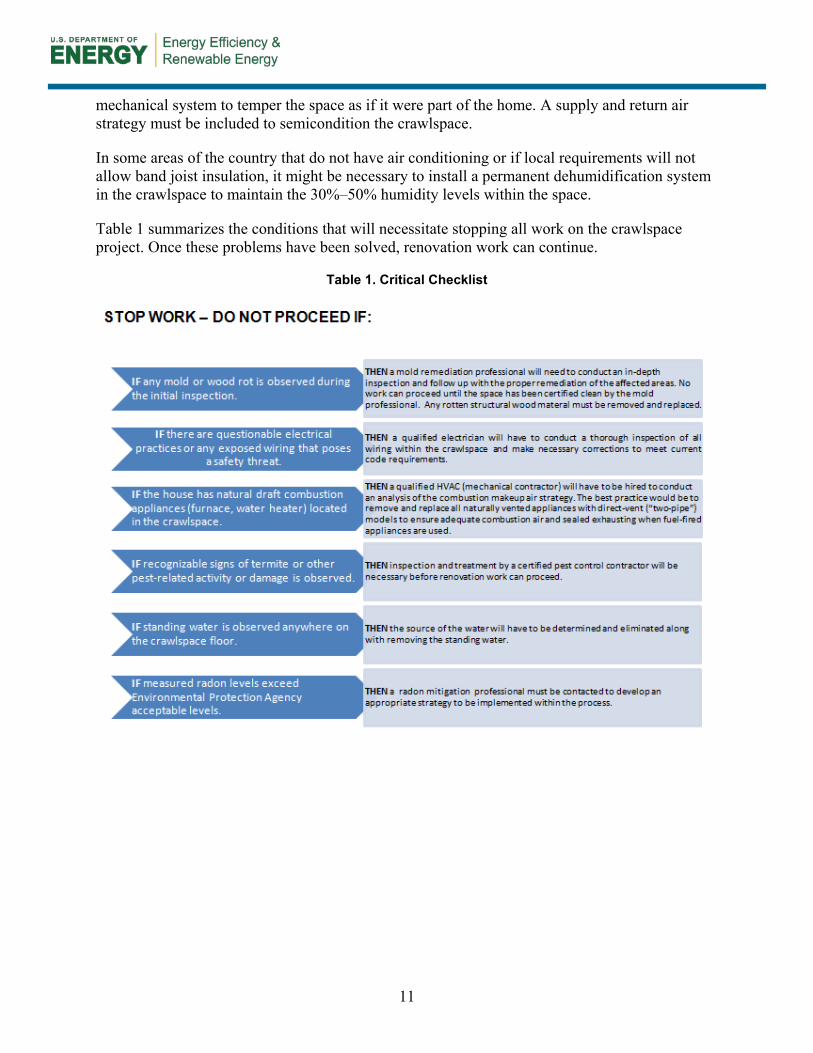
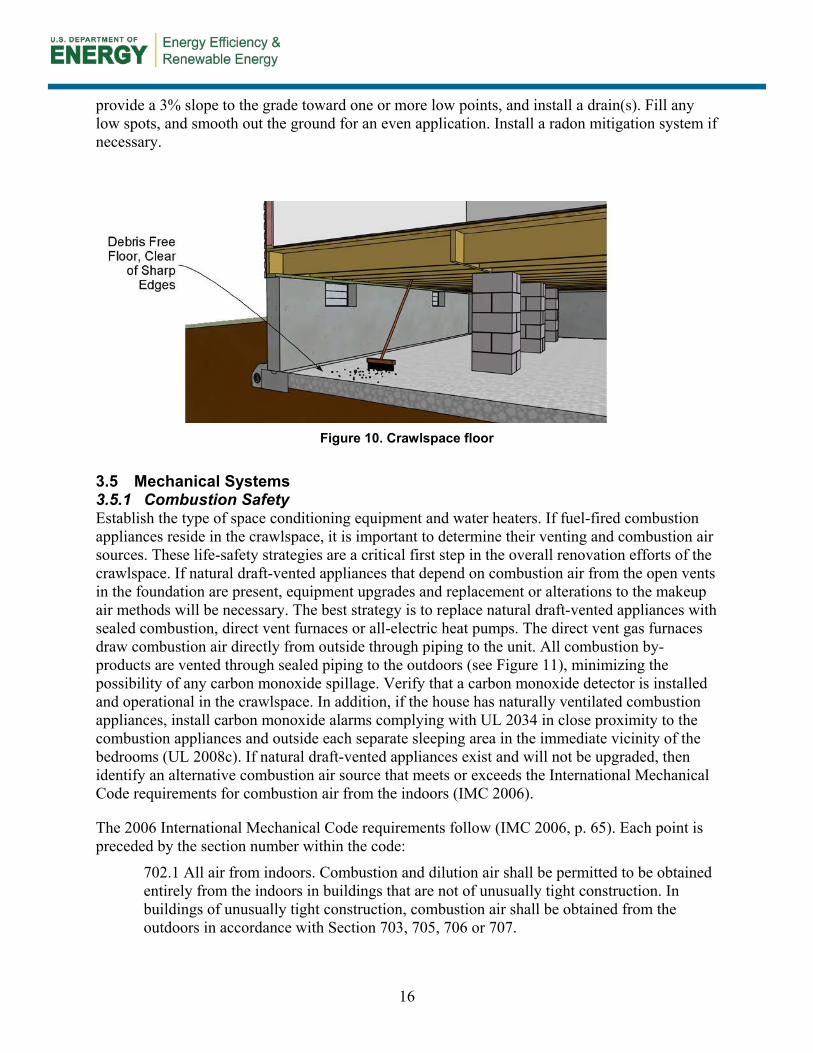
This section contains guidance on the ideal work sequencing when retrofitting a crawlspace. It is up to the professional contractor to sequence the work so moisture is not trapped within any of the building assemblies. Appendix A includes work plans and checklists to guide the work sequence, and Appendix B presents complete material specifications. During the sealing process, the contractor must follow safe work practices to minimize any effects from sealants or adhesive fumes on workers’ health. Temporary ventilation could be necessary during the installations. 3.1 Exterior Moisture Controlling bulk water on the exterior of the building is the first step when retrofitting a crawlspace. Ensure that all of the details to control bulk water that were identified during the evaluation process have been examined and corrected where necessary. For example, bulk water from the roof can be drained away from the foundation via downspouts that are connected to a storm sewer or collector crock pit, and bulk groundwater against the foundation can be drained away through a perimeter foundation drain system (see Figure 6). Here are some additional specifics:
• The moisture content of the wood in the crawlspace must remain below 17%. Moisture content greater than 17% is of concern and should be investigated.
• Ideally, grading around the perimeter of the building has a 5% slope away from the foundation (6 in. within 10 ft). If this is unachievable, evaluate the landscaping. Drainage swales or grade gutters might need to be implemented around the perimeter of the foundation.
• All sprinkler flow must be directed away from the home.
• All roof runoff must be directed away from the building a minimum of 10 ft or via an underground drain system.
3.2 Exterior Waterproofing and Drainage Depending on site conditions, if there is high groundwater or recognizable bulk water flow against the foundation that cannot be remediated any other way, implementing a waterproofing or damp-proofing strategy might be necessary. Waterproofing or damp-proofing (at a minimum) of all below-grade portions of the foundation and continuous perimeter drains might be required to prevent subsurface groundwater from saturating the foundation system.
13
Figure 6. Water management to keep bulk water away from the crawlspace
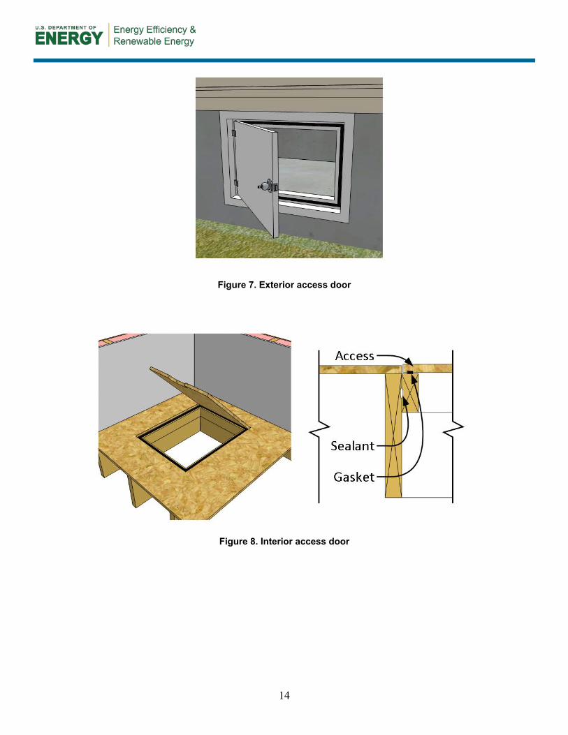
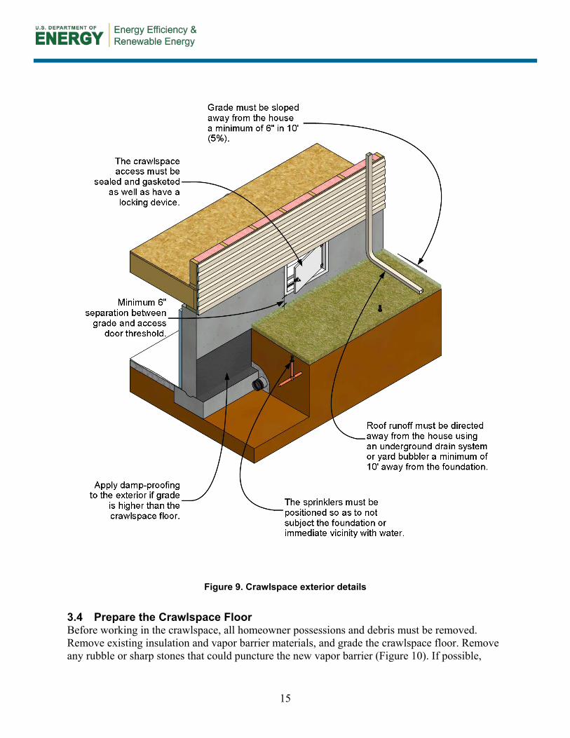
3.3 Crawlspace Access The general location and overall weather seal of the access door must be inspected. The access door (Figure 7) must be a minimum of 6 in. above exterior grade to prevent runoff or snowmelt from entering. The door needs to be made of a noncorroding material, and the opening must have weather stripping to prevent moisture and air from entering the space. Installing a lock on the door is recommended once all detailing is complete.
Constructing a well around the opening with proper drainage at the base may be necessary if the access is too low and in contact with grade. Another method for providing access would be to install a new scuttle hole (Figure 8) through the floor system if a well is not desirable.
The 2009 IRC, Section R408.4, Access, states the following (IRC 2009c, p. 108):
Access shall be provided to all under-floor spaces. Access openings through the floor shall be a minimum of 18 inches by 24 inches (457 mm by 610 mm). Openings through a perimeter wall shall be not less than 16 inches by 24 inches (407 mm by 610 mm). When any portion of the through-wall access is below grade, an areaway not less than 16 inches by 24 inches (407 mm by 610 mm) shall be provided. The bottom of the areaway shall be below the threshold of the access opening. Throughwall access openings shall not be located under a door to the residence. See Section M1305.1.4 for access requirements where mechanical equipment is located under floors.
Figure 9 details a crawlspace exterior.
14
Figure 7. Exterior access door
Figure 8. Interior access door
15
Figure 9. Crawlspace exterior details
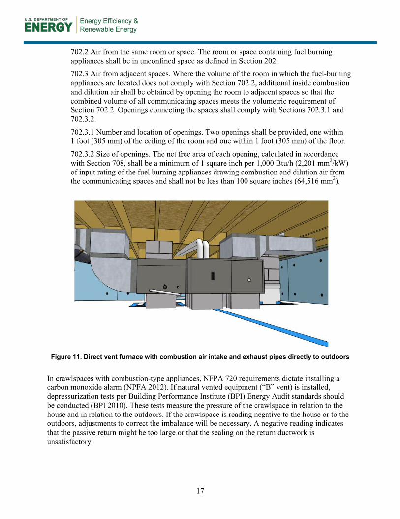
3.4 Prepare the Crawlspace Floor Before working in the crawlspace, all homeowner possessions and debris must be removed. Remove existing insulation and vapor barrier materials, and grade the crawlspace floor. Remove any rubble or sharp stones that could puncture the new vapor barrier (Figure 10). If possible,
16
provide a 3% slope to the grade toward one or more low points, and install a drain(s). Fill any low spots, and smooth out the ground for an even application. Install a radon mitigation system if necessary.
Figure 10. Crawlspace floor
3.5 Mechanical Systems
Combustion Safety 3.5.1Establish the type of space conditioning equipment and water heaters. If fuel-fired combustion appliances reside in the crawlspace, it is important to determine their venting and combustion air sources. These life-safety strategies are a critical first step in the overall renovation efforts of the crawlspace. If natural draft-vented appliances that depend on combustion air from the open vents in the foundation are present, equipment upgrades and replacement or alterations to the makeup air methods will be necessary. The best strategy is to replace natural draft-vented appliances with sealed combustion, direct vent furnaces or all-electric heat pumps. The direct vent gas furnaces draw combustion air directly from outside through piping to the unit. All combustion by-products are vented through sealed piping to the outdoors (see Figure 11), minimizing the possibility of any carbon monoxide spillage. Verify that a carbon monoxide detector is installed and operational in the crawlspace. In addition, if the house has naturally ventilated combustion appliances, install carbon monoxide alarms complying with UL 2034 in close proximity to the combustion appliances and outside each separate sleeping area in the immediate vicinity of the bedrooms (UL 2008c). If natural draft-vented appliances exist and will not be upgraded, then identify an alternative combustion air source that meets or exceeds the International Mechanical Code requirements for combustion air from the indoors (IMC 2006).
The 2006 International Mechanical Code requirements follow (IMC 2006, p. 65). Each point is preceded by the section number within the code:
702.1 All air from indoors. Combustion and dilution air shall be permitted to be obtained entirely from the indoors in buildings that are not of unusually tight construction. In buildings of unusually tight construction, combustion air shall be obtained from the outdoors in accordance with Section 703, 705, 706 or 707.
17
702.2 Air from the same room or space. The room or space containing fuel burning appliances shall be in unconfined space as defined in Section 202.
702.3 Air from adjacent spaces. Where the volume of the room in which the fuel-burning appliances are located does not comply with Section 702.2, additional inside combustion and dilution air shall be obtained by opening the room to adjacent spaces so that the combined volume of all communicating spaces meets the volumetric requirement of Section 702.2. Openings connecting the spaces shall comply with Sections 702.3.1 and 702.3.2.
702.3.1 Number and location of openings. Two openings shall be provided, one within 1 foot (305 mm) of the ceiling of the room and one within 1 foot (305 mm) of the floor.
702.3.2 Size of openings. The net free area of each opening, calculated in accordance with Section 708, shall be a minimum of 1 square inch per 1,000 Btu/h (2,201 mm2/kW) of input rating of the fuel burning appliances drawing combustion and dilution air from the communicating spaces and shall not be less than 100 square inches (64,516 mm2).
Figure 11. Direct vent furnace with combustion air intake and exhaust pipes directly to outdoors
In crawlspaces with combustion-type appliances, NFPA 720 requirements dictate installing a carbon monoxide alarm (NPFA 2012). If natural vented equipment (“B” vent) is installed, depressurization tests per Building Performance Institute (BPI) Energy Audit standards should be conducted (BPI 2010). These tests measure the pressure of the crawlspace in relation to the house and in relation to the outdoors. If the crawlspace is reading negative to the house or to the outdoors, adjustments to correct the imbalance will be necessary. A negative reading indicates that the passive return might be too large or that the sealing on the return ductwork is unsatisfactory.
18
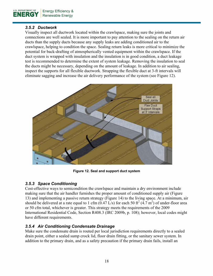
Ductwork 3.5.2Visually inspect all ductwork located within the crawlspace, making sure the joints and connections are well sealed. It is more important to pay attention to the sealing on the return air ducts than the supply ducts because any supply leaks are adding conditioned air to the crawlspace, helping to condition the space. Sealing return leaks is more critical to minimize the potential for back-drafting of atmospherically vented equipment within the crawlspace. If the duct system is wrapped with insulation and the insulation is in good condition, a duct leakage test is recommended to determine the extent of system leakage. Removing the insulation to seal the ducts might be necessary, depending on the amount of leakage. In addition to air sealing, inspect the supports for all flexible ductwork. Strapping the flexible duct at 3-ft intervals will eliminate sagging and increase the air delivery performance of the system (see Figure 12).
Figure 12. Seal and support duct system
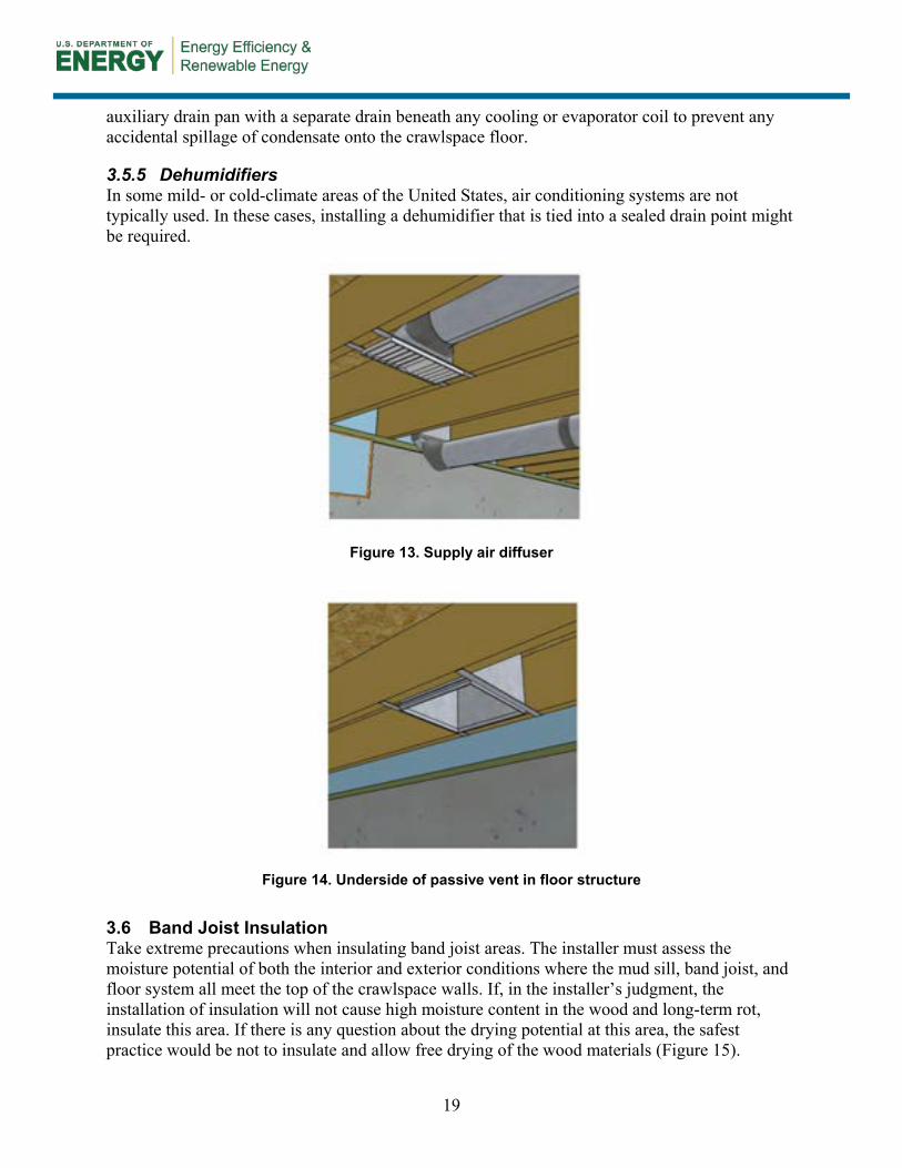
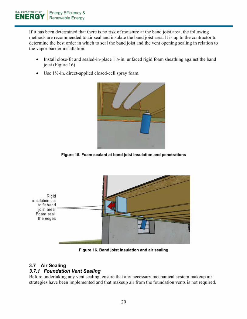
Space Conditioning 3.5.3Cost-effective ways to semicondition the crawlspace and maintain a dry environment include making sure that the air handler furnishes the proper amount of conditioned supply air (Figure 13) and implementing a passive return strategy (Figure 14) to the living space. At a minimum, air should be delivered at a rate equal to 1 cfm (0.47 L/s) for each 50 ft2 (4.7 m2) of under-floor area or 50 cfm total, whichever is greater. This strategy meets the requirements of the 2009 International Residential Code, Section R408.3 (IRC 2009b, p. 108); however, local codes might have different requirements.
Air Conditioning Condensate Drainage 3.5.4Make sure the condensate drain is routed per local jurisdiction requirements directly to a sealed drain point, either a sealed sump crock lid, floor drain fitting, or the sanitary sewer system. In addition to the primary drain, and as a safety precaution if the primary drain fails, install an
19
auxiliary drain pan with a separate drain beneath any cooling or evaporator coil to prevent any accidental spillage of condensate onto the crawlspace floor.
Dehumidifiers 3.5.5In some mild- or cold-climate areas of the United States, air conditioning systems are not typically used. In these cases, installing a dehumidifier that is tied into a sealed drain point might be required.
Figure 13. Supply air diffuser
Figure 14. Underside of passive vent in floor structure
3.6 Band Joist Insulation Take extreme precautions when insulating band joist areas. The installer must assess the moisture potential of both the interior and exterior conditions where the mud sill, band joist, and floor system all meet the top of the crawlspace walls. If, in the installer’s judgment, the installation of insulation will not cause high moisture content in the wood and long-term rot, insulate this area. If there is any question about the drying potential at this area, the safest practice would be not to insulate and allow free drying of the wood materials (Figure 15).
20
If it has been determined that there is no risk of moisture at the band joist area, the following methods are recommended to air seal and insulate the band joist area. It is up to the contractor to determine the best order in which to seal the band joist and the vent opening sealing in relation to the vapor barrier installation.
• Install close-fit and sealed-in-place 1½-in. unfaced rigid foam sheathing against the band joist (Figure 16)
• Use 1½-in. direct-applied closed-cell spray foam.
Figure 15. Foam sealant at band joist insulation and penetrations
Figure 16. Band joist insulation and air sealing
3.7 Air Sealing Foundation Vent Sealing 3.7.1
Before undertaking any vent sealing, ensure that any necessary mechanical system makeup air strategies have been implemented and that makeup air from the foundation vents is not required.
21
Once the mechanical system air requirements have been verified, remove or patch over and seal all intentional, operable, or fixed foundation vents to prevent outside air from being drawn into the crawlspace. If any vents are below grade, seal them from the outside with brick, block, or concrete, and then insulate them from the inside. If the vent is to remain, verify that when the vent is closed, it will function as a pest-resistant barrier, or install a pest-resistant barrier if needed. If the vent is being removed, create a durable pest- and weather-resistant barrier on the outside of any vent opening.
To seal the vent from the inside, follow these steps:
• Measure and cut pieces of 2-in. extruded polystyrene rigid foam insulation to fit loosely over the vent area (see Figure 17).
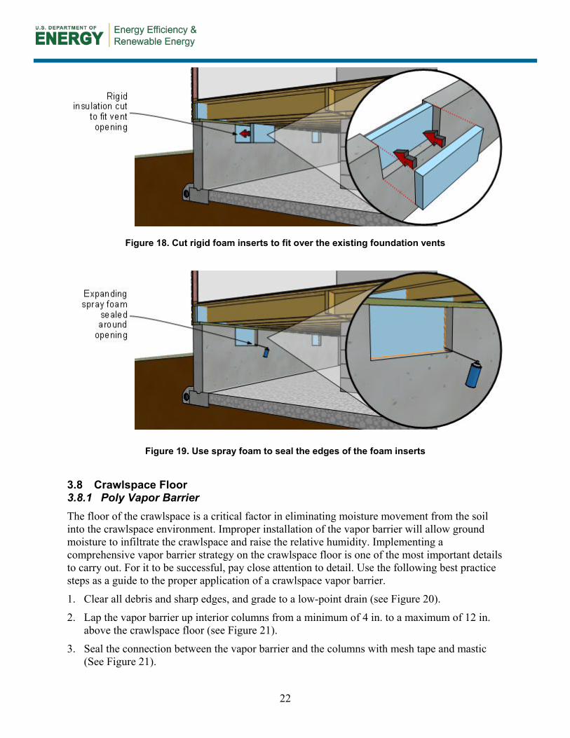
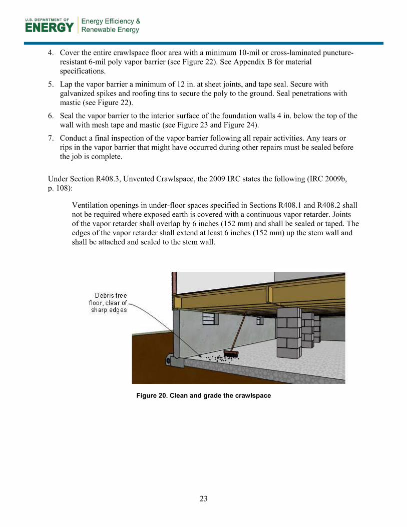
• Cut, install, and seal the perimeter of the foam to the openings with expanding spray foam (see Figure 18 and Figure 19).
• Consider the alternative of removing the vents and, if sizing is appropriate, replacing them with glass block that is mortared in place. This method allows some daylighting into the space.
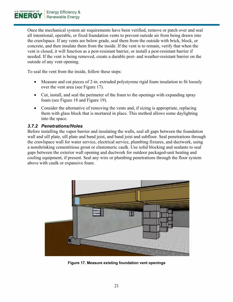
Penetrations/Holes 3.7.2Before installing the vapor barrier and insulating the walls, seal all gaps between the foundation wall and sill plate, sill plate and band joist, and band joist and subfloor. Seal penetrations through the crawlspace wall for water service, electrical service, plumbing fixtures, and ductwork, using a nonshrinking cementitious grout or elastomeric caulk. Use solid blocking and sealants to seal gaps between the exterior wall opening and ductwork for outdoor packaged-unit heating and cooling equipment, if present. Seal any wire or plumbing penetrations through the floor system above with caulk or expansive foam.
Figure 17. Measure existing foundation vent openings
22
Figure 18. Cut rigid foam inserts to fit over the existing foundation vents
Figure 19. Use spray foam to seal the edges of the foam inserts
3.8 Crawlspace Floor Poly Vapor Barrier 3.8.1
The floor of the crawlspace is a critical factor in eliminating moisture movement from the soil into the crawlspace environment. Improper installation of the vapor barrier will allow ground moisture to infiltrate the crawlspace and raise the relative humidity. Implementing a comprehensive vapor barrier strategy on the crawlspace floor is one of the most important details to carry out. For it to be successful, pay close attention to detail. Use the following best practice steps as a guide to the proper application of a crawlspace vapor barrier.
1. Clear all debris and sharp edges, and grade to a low-point drain (see Figure 20).
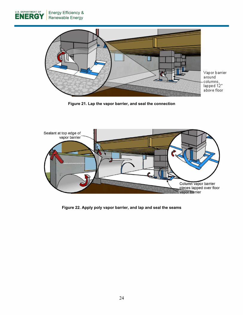
2. Lap the vapor barrier up interior columns from a minimum of 4 in. to a maximum of 12 in. above the crawlspace floor (see Figure 21).
3. Seal the connection between the vapor barrier and the columns with mesh tape and mastic (See Figure 21).
23
4. Cover the entire crawlspace floor area with a minimum 10-mil or cross-laminated puncture-resistant 6-mil poly vapor barrier (see Figure 22). See Appendix B for material specifications.
5. Lap the vapor barrier a minimum of 12 in. at sheet joints, and tape seal. Secure with galvanized spikes and roofing tins to secure the poly to the ground. Seal penetrations with mastic (see Figure 22).
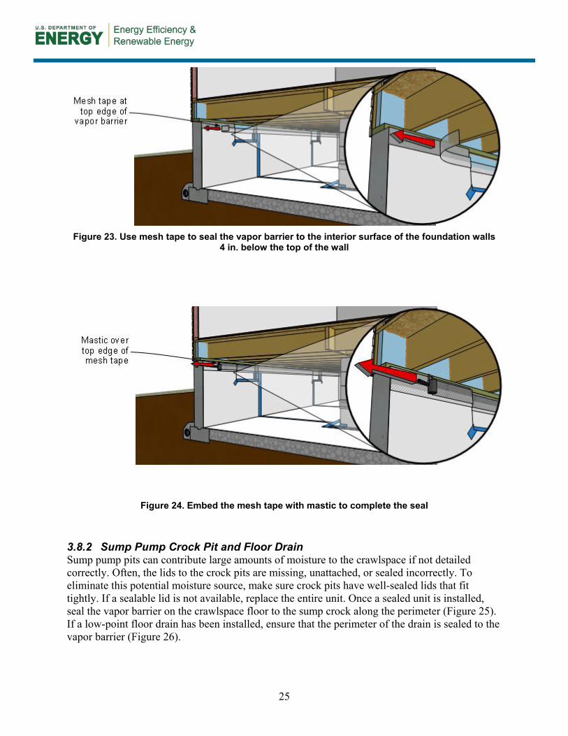
6. Seal the vapor barrier to the interior surface of the foundation walls 4 in. below the top of the wall with mesh tape and mastic (see Figure 23 and Figure 24).
7. Conduct a final inspection of the vapor barrier following all repair activities. Any tears or rips in the vapor barrier that might have occurred during other repairs must be sealed before the job is complete.
Under Section R408.3, Unvented Crawlspace, the 2009 IRC states the following (IRC 2009b, p. 108):
Ventilation openings in under-floor spaces specified in Sections R408.1 and R408.2 shall not be required where exposed earth is covered with a continuous vapor retarder. Joints of the vapor retarder shall overlap by 6 inches (152 mm) and shall be sealed or taped. The edges of the vapor retarder shall extend at least 6 inches (152 mm) up the stem wall and shall be attached and sealed to the stem wall.
Figure 20. Clean and grade the crawlspace
24
Figure 21. Lap the vapor barrier, and seal the connection
Figure 22. Apply poly vapor barrier, and lap and seal the seams
25
Figure 23. Use mesh tape to seal the vapor barrier to the interior surface of the foundation walls
4 in. below the top of the wall
Figure 24. Embed the mesh tape with mastic to complete the seal
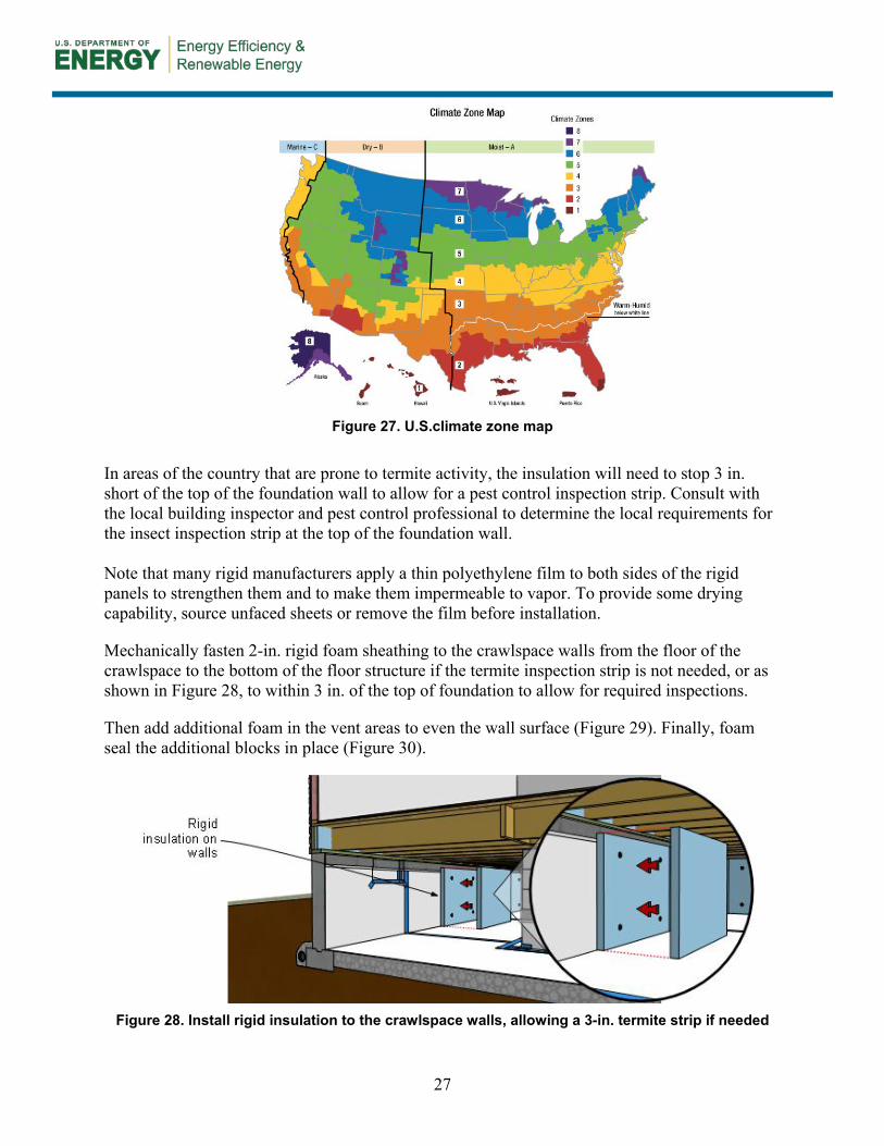
Sump Pump Crock Pit and Floor Drain 3.8.2Sump pump pits can contribute large amounts of moisture to the crawlspace if not detailed correctly. Often, the lids to the crock pits are missing, unattached, or sealed incorrectly. To eliminate this potential moisture source, make sure crock pits have well-sealed lids that fit tightly. If a sealable lid is not available, replace the entire unit. Once a sealed unit is installed, seal the vapor barrier on the crawlspace floor to the sump crock along the perimeter (Figure 25). If a low-point floor drain has been installed, ensure that the perimeter of the drain is sealed to the vapor barrier (Figure 26).
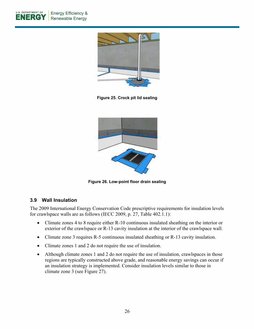
26
Figure 25. Crock pit lid sealing
Figure 26. Low-point floor drain sealing
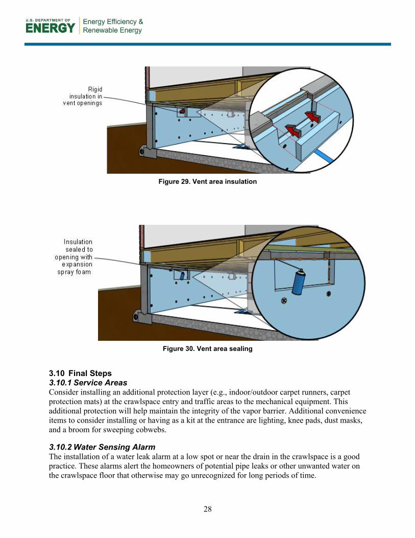
3.9 Wall Insulation The 2009 International Energy Conservation Code prescriptive requirements for insulation levels for crawlspace walls are as follows (IECC 2009, p. 27, Table 402.1.1):
• Climate zones 4 to 8 require either R-10 continuous insulated sheathing on the interior or exterior of the crawlspace or R-13 cavity insulation at the interior of the crawlspace wall.
• Climate zone 3 requires R-5 continuous insulated sheathing or R-13 cavity insulation.
• Climate zones 1 and 2 do not require the use of insulation.
• Although climate zones 1 and 2 do not require the use of insulation, crawlspaces in those regions are typically constructed above grade, and reasonable energy savings can occur if an insulation strategy is implemented. Consider insulation levels similar to those in climate zone 3 (see Figure 27).
27
Figure 27. U.S.climate zone map
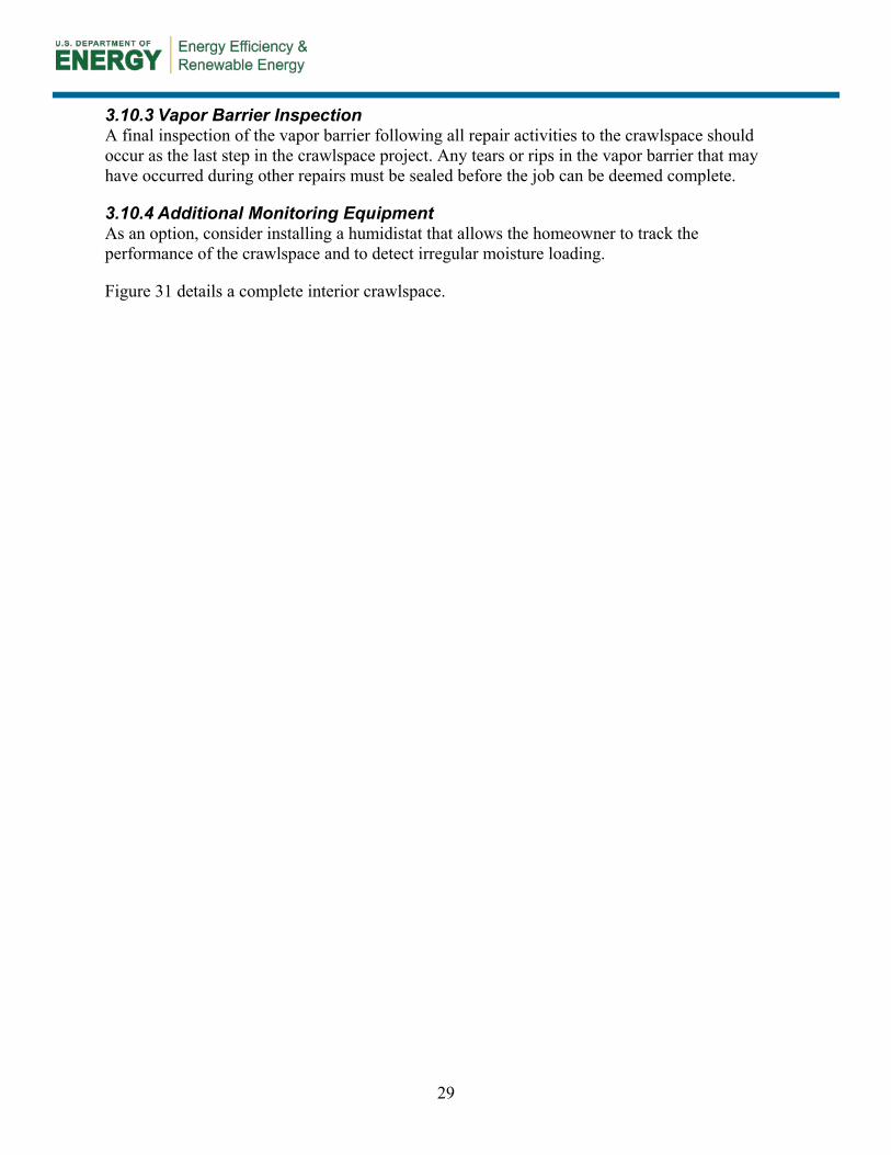
In areas of the country that are prone to termite activity, the insulation will need to stop 3 in. short of the top of the foundation wall to allow for a pest control inspection strip. Consult with the local building inspector and pest control professional to determine the local requirements for the insect inspection strip at the top of the foundation wall. Note that many rigid manufacturers apply a thin polyethylene film to both sides of the rigid panels to strengthen them and to make them impermeable to vapor. To provide some drying capability, source unfaced sheets or remove the film before installation.
Mechanically fasten 2-in. rigid foam sheathing to the crawlspace walls from the floor of the crawlspace to the bottom of the floor structure if the termite inspection strip is not needed, or as shown in Figure 28, to within 3 in. of the top of foundation to allow for required inspections.
Then add additional foam in the vent areas to even the wall surface (Figure 29). Finally, foam seal the additional blocks in place (Figure 30).
Figure 28. Install rigid insulation to the crawlspace walls, allowing a 3-in. termite strip if needed
28
Figure 29. Vent area insulation
Figure 30. Vent area sealing
3.10 Final Steps Service Areas 3.10.1
Consider installing an additional protection layer (e.g., indoor/outdoor carpet runners, carpet protection mats) at the crawlspace entry and traffic areas to the mechanical equipment. This additional protection will help maintain the integrity of the vapor barrier. Additional convenience items to consider installing or having as a kit at the entrance are lighting, knee pads, dust masks, and a broom for sweeping cobwebs.
Water Sensing Alarm 3.10.2The installation of a water leak alarm at a low spot or near the drain in the crawlspace is a good practice. These alarms alert the homeowners of potential pipe leaks or other unwanted water on the crawlspace floor that otherwise may go unrecognized for long periods of time.
29
Vapor Barrier Inspection 3.10.3A final inspection of the vapor barrier following all repair activities to the crawlspace should occur as the last step in the crawlspace project. Any tears or rips in the vapor barrier that may have occurred during other repairs must be sealed before the job can be deemed complete.
Additional Monitoring Equipment 3.10.4As an option, consider installing a humidistat that allows the homeowner to track the performance of the crawlspace and to detect irregular moisture loading.
Figure 31 details a complete interior crawlspace.
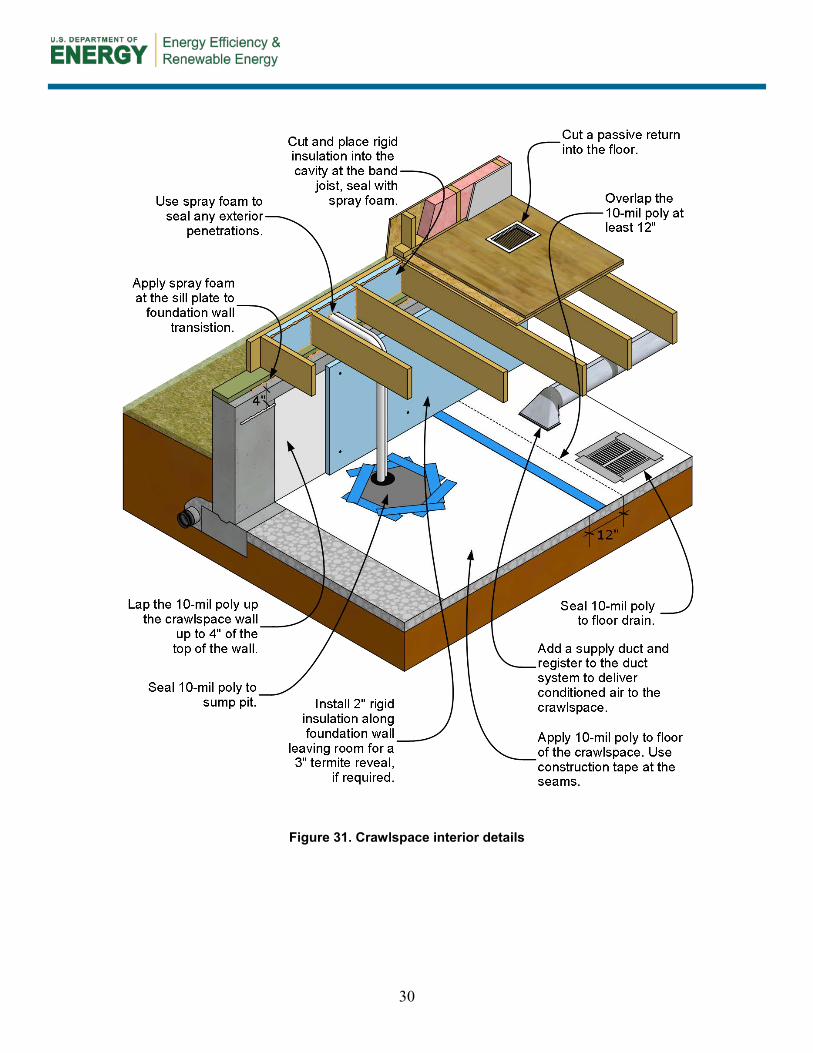
30
Figure 31. Crawlspace interior details
31
4 Homeowner Education
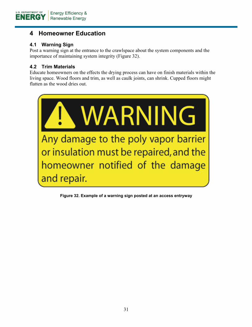
4.1 Warning Sign Post a warning sign at the entrance to the crawlspace about the system components and the importance of maintaining system integrity (Figure 32).
4.2 Trim Materials Educate homeowners on the effects the drying process can have on finish materials within the living space. Wood floors and trim, as well as caulk joints, can shrink. Cupped floors might flatten as the wood dries out.
Figure 32. Example of a warning sign posted at an access entryway
32
Glossary
Combustion Air The air provided to fuel-burning equipment, including air for fuel combustion, draft hood dilution, and ventilation of the equipment enclosure (IRC 2006, Section R202, p. 11)
Condensate The liquid that separates from a gas due to a reduction in temperature (e.g., water that condenses from flue gases and water that condenses from air circulating through the cooling coil in air conditioning equipment; IRC 2006, Section 202, p.11)
Confined Space A room or space having a volume less than 50 ft3 per 1,000 Btu/h (4.83 L/W) of the aggregate input rating of all fuel-burning appliances installed in that space (IRC 2006, Section 202, p. 11)
Damp-Proofing A water-resistant coating designed to shed water and resist soil moisture
Permeability (Perm)
A measure of the diffusion of water vapor through a material at standard test conditions; there are dry cup and wet cup tests, and they sometimes yield different perm ratings
Semiconditioning A method of providing intentional supply air to a space that will likely deviate by 5°F–10°F (or more) from the main thermostat set point
Waterproofing A continuous membrane covering that will resist standing water or water under hydrostatic pressure
Yard Bubbler A drain pot installed over a dry well of rock that allows bulk water drainage to the soil through percolation; during extreme conditions, it allows an overflow to the surface through the bubble lid
33
References
Advanced Energy (2005). Field Study Final Report: A Field Study Comparison of the Energy and Moisture Performance Characteristics of Ventilated Versus Sealed Crawl Spaces in the South. Raleigh, NC: Advanced Energy. Accessed November 1, 2012. http://www.advancedenergy.org/buildings/knowledge_library/crawl_spaces/pdfs/Field%20Study%20-%202005.pdf.
Advanced Energy (2012). Closed Crawl Spaces: An Introduction to Design, Construction and Performance. Raleigh, NC: Advanced Energy. Accessed November 1, 2012: http://www.advancedenergy.org/buildings/knowledge_library/crawl_spaces/pdfs/Closed%20Crawl%20Spaces_An%20Introduction%20for%20the%20Southeast.pdf.
ASTM C177. ASTM C177 – 10 Standard Test Method for Steady-State Heat Flux Measurements and Thermal Transmission Properties by Means of the Guarded Hot-Plate Apparatus. West Conshohocken, PA: ASTM International.
ASTM C509. ASTM C509 – 06(2011) Standard Specification for Elastomeric Cellular Preformed Gasket and Sealing Material. West Conshohocken, PA: ASTM International.
ASTM C518. ASTM C518 – 10 Standard Test Method for Steady-State Thermal Transmission Properties by Means of Heat Flow Meter Apparatus. West Conshohocken, PA: ASTM International.
ASTM C920. ASTM C920 – 11 Standard Specification for Elastomeric Joint Sealants. West Conshohocken, PA: ASTM International.
ASTM C1642. ASTM C1642 – 07 Standard Practice for Determining Air Leakage Rates of Aerosol Foam Sealants and Other Construction Joint Fill and Insulation Materials. West Conshohocken, PA: ASTM International.
ASTM D882. ASTM D882 – 12 Standard Test Method for Tensile Properties of Thin Plastic Sheeting. West Conshohocken, PA: ASTM International.
ASTM D3330. ASTM D3330/D3330M – 04(2010) Standard Test Method for Peel Adhesion of Pressure Sensitive Tape. West Conshohocken, PA: ASTM International.
ASTM E84. ASTM E-84 – 12b Standard Test Method for Surface Burning Characteristics of Building Materials. West Conshohocken, PA: ASTM International.
ASTM E283. ASTM E283 – 04(2012) Standard Test Method for Determining Rate of Air Leakage Through Exterior Windows, Curtain Walls, and Doors Under Specified Pressure Differences Across the Specimen. West Conshohocken, PA: ASTM International.
ASTM E1745. ASTM E1745 – 11 Standard Specification for Plastic Water Vapor Retarders Used in Contact with Soil or Granular Fill under Concrete Slabs. West Conshohocken, PA: ASTM International.
34
ASTM E2178. ASTM E2178 – 11 Standard Test Method for Air Permeance of Building Materials. West Conshohocken, PA: ASTM International.
BPI (2010). BPI-101 Home Energy Auditing Standard, Sections 7 and 3.2. Malta, NY: Building Performance Institute.
BSC (2004). Conditioned Crawl Space Construction, Performance and Code. Somerville, MA: Building Science Corporation. Accessed November 1, 2012: http://www.buildingscience.com/documents/reports/rr-0401-conditioned-crawlspace-construction-performance-and-codes.
Federal Register (2005). Part IV Federal Trade Commission, 16 CFR Part 460 Labeling and Advertising of Home Insulation: Trade Regulations Rule; Final Rule. Federal Register, Vol. 70, No. 103, May 31, 2005. Washington, DC: U.S. Government Printing Office.
ICC-ES AC12. Acceptance Criteria for Foam Plastic Insulation. Whittier, CA: International Code Council Evaluation Service.
ICC-ES AC377. Acceptance Criteria for Spray-Applied Foam Plastic Insulation. Whittier, CA: International Code Council Evaluation Service.
IECC (2009). 2009 International Energy Conservation Code. Country Club Hills, IL: International Code Council, Inc.
IMC (2006). 2006 International Mechanical Code, Sections 702.1, 702.2, 702.3, 702.3.1, and 702.3.2. Country Club Hills, IL: International Code Council, Inc.
IRC (2006). 2006 International Residential Code, Section 202. Country Club Hills, IL: International Code Council, Inc., p. 11.
IRC (2009a). 2009 International Residential Code, Section R405.2.3. Country Club Hills, IL: International Code Council, Inc., p. 107.
IRC (2009b). 2009 International Residential Code, Section R408.3. Country Club Hills, IL: International Code Council, Inc.
IRC (2009c). 2009 International Residential Code, Section R408.4. Country Club Hills, IL: International Code Council, Inc.
NFPA (2009). NFPA 720: Standard for the Installation of Carbon Monoxide (CO) Detection and Warning Equipment. Quincy, MA: National Fire Protection Association.
UL 181 (2008a). UL 181A. Closure Systems for Use with Rigid Air Ducts. Camas, WA: UL. Accessed November 1, 2012: http://www.ul.com/global/eng/pages/solutions/standards/accessstandards/catalogofstandards/standard/?id=181A_3.

35
UL 181 (2008b). UL 181B. Closure Systems for Use with Flexible Air Ducts and Air Connectors. Camas, WA: UL. Accessed November 1, 2012: http://www.ul.com/global/eng/pages/solutions/standards/accessstandards/catalogofstandards/standard/?id=181B_2
UL 2034 (2008c). Standard for Single and Multiple Station Carbon Monoxide Alarms. Camas, WA: UL. Accessed November 1, 2012: http://www.ul.com/global/eng/pages/solutions/standards/accessstandards/catalogofstandards/standard/?id=2034_3.
36
Appendix A: Work Plans and Checklists
Stop-Work Items The framing in the crawlspace has mold growing on the surface.
• YES – A mold remediation professional will need to be hired to conduct a thorough inspection and remediation.
• NO – Proceed. There are exposed wiring and questionable electrical practices.
• YES – The crawlspace will need to be inspected by a qualified electrician and the necessary repairs made.
• NO – Proceed. There are atmospherically (“B”) vented appliances located in the crawlspace.
• YES – A qualified mechanical contractor will need to analyze the current equipment, and a new strategy of equipment replacement or alternative combustion air sources will need to be determined.
• NO – Proceed. There are signs of termite activity.
• YES – A certified pest control contractor will need to conduct inspection and treatment. • NO – Proceed.
The crawlspace environment is saturated with moisture. • YES – Temporary dehumidifiers will need to be run to reduce humidity levels to between 30% to
50%. • NO – Proceed.
There is standing water on the floor of the crawlspace. • YES – The source will need to be identified and corrected and the standing water removed. • NO – Proceed.
There is a high radon level measured in the crawlspace. • YES – A radon mitigation strategy must be implemented within the process of closing the
crawlspace. • NO – Proceed.
Exterior Walk-Through 1. Roof drainage strategy
• Gutters at all roof eaves _______ • Downspout discharge distance _______ ft
2. Grading • Site grading slopes a minimum of 5% away from the foundation (6 in. fall over a 10-ft run).
YES_______ NO_______ 3. Sprinklers
• Activated and direction of flow away from the building _______ 4. Foundation waterproofing
• Damp-proofing applied below grade_______ • Footing drains discharge location _______
5. Access door • Size of opening _______
37
• Grade clearance to threshold _______ Weather stripping installed YES_______ Location ____________________
Interior Walk-Through
Mechanical Systems 1. Locate the mechanical systems within the crawlspace. If natural draft exhaust appliances are
installed in the crawlspace, combustion air zone (CAZ) testing per BPI standards has been conducted and compliance assured.
2. Calculate necessary combustion air strategy to meet 2009 IRC 702.3.2: • 1 in.2 per 1,000 Btu/h and not less than 100 in.2
3. Mechanical equipment • Furnace type, model, and manufacturer ____________________ • Water heater type, model, and manufacturer ____________________
4. Ductwork sealing • Supply duct joints and seams sealed with mastic _______ • Return air ductwork sealed with mastic _______
5. Space conditioning • Under floor area _______ ft2 • Supply air volume set to local code requirements _______cfm • Passive return or pathway to common area above floor _______
6. Condensate drainage • Drain routing direct to drain point _______
7. Carbon monoxide alarm • Working alarm installed in the CAZ per NFPA 720 _______
8. Air pressure testing • CAZ testing performed per BPI standards _______
Air Sealing 1. Foundation vent openings
• Vents closed and rigid foam blocks installed _______ • Foam blocks sealed with expanding foam _______
2. Penetrations • Sill plate to top of foundation wall sealed_______ • Pipe penetrations sealed _______ • Cracks or holes sealed, if applicable _______
3. Crawlspace floor • Vapor barrier type and millage ____________________ • Vapor barrier installation
• Floors: All seams sealed with construction tape _______ • Floors: Penetrations sealed with construction tape _______ • Floors: Sump pit crock lid sealed to vapor barrier _______ • Floors: Floor drains sealed to vapor barrier _______ • Walls: Top of barrier set in sealant _______ • Columns: Vertical distance of barrier on column from floor _______ inches
38
Thermal 1. Wall insulation type ____________________
• Pest inspection gap size at top of wall _______inches 2. Insulation permanently fixed to wall _______
• Rigid insulation type meets local fire requirements _______ • Band joist insulation size and type_______ • Foam blocks in band area sealed to framing _______
Homeowner Awareness 1. Warning sign installed within entryway _______ 2. Floor protection barrier
• Additional protection barrier installed at entryway floor _______ • Additional protection barrier installed at traffic areas ________ • Humidistat (optional) _______ • Water sensing alarm _______

39
Appendix B: Material Specifications
Air Barrier. Any rigid or semi-rigid material that does not allow air to pass through it. Examples are gypsum board, plywood/oriented strand board, foam board, duct board (with a facing flame spread rating of 25 or less), sheet metal, or dimensional lumber. Relevant Test Methods: ASTM E2178 and E283 Insulation. Any material that significantly slows or retards the flow or transfer of heat. Building insulation types are classified according to form (e.g., loose-fill, batt, flexible, rigid, reflective, foamed-in-place) or material (e.g., mineral fiber, organic fiber, foam plastic). Relevant Test Methods: ASTM C177, ASTM C518, CFR Title 16, Part 460 Rigid Foam. Rigid board material that provides thermal resistance. Examples are foam plastic such as expanded polystyrene, extruded polystyrene, and polyisocyanurate. Relevant Test Methods: ASTM C177, ASTM C518, ICC-ES AC12, CFR Title 16, Part 460 Sealant. Any flexible product that, when applied to the joint of two or more materials, will adhere and permanently seal the joint to the passage of air. Examples are caulk, foam, and mastic. Relevant Test Method: Foam sealants—ASTM C1642 Relevant Test Method: Acrylic, silicone, and urethane caulk—ASTM C-920 Required Certification: Water-based duct sealant—UL 181A-M, UL 181B-M Spray Foam Relevant Test Methods: ICC-ES AC377, ASTM E84, CFR Title 16, Part 460 Tape. (For ducts) Required Certification: UL-181 Tape. (For air sealing) Relevant Test Methods: ASTM D3330, ASTM D882 Vapor Barrier. Polyethylene sheeting that prohibits the passage of bulk water and vapor. Relevant Test Method: ASTM E1745 Weather-Stripping. Relevant Test Method: ASTM C509
Printed with a renewable-source ink on paper containing at least 50% wastepaper, including 10% post-consumer waste.
DOE/GO-102013-3587 ▪ January 2013