Guide to applying for a building consent (residential buildings ...
64
Guide to applying for a building consent (residential buildings) Second Edition October 2010
Transcript of Guide to applying for a building consent (residential buildings ...

Guide to applying for a building consent (residential buildings)
Second Edition October 2010

AbOut thiS GuidE 1
intrOductiOn 2
1.0 thE buildinG cOnSEnt prOcESS 3
2.0 plAnS And SpEcificAtiOnS 10
3.0 dESiGn SummAry 13
4.0 dESiGn SummAry chEck ShEEt 16
5.0 drAwinGS 19 5.1 Site plan 20 5.2 Location plan 22 5.3 Foundation plan 24 5.4 Roof framing plan 26 5.5 Floor plan 28 5.6 Exterior elevations 30 5.7 Sections 32 5.8 Construction details 34 5.9 Door/window schedule 38 5.10 Plumbing layout or schematic plan 40 5.11 Electrical plan 42 5.12 Wet area details 44 5.13 Additional drawings 46
6.0 rElAtEd buildinG cOnSEnt ApplicAtiOn mAttErS 47
7.0 rElAtEd buildinG Act mAttErS 52
8.0 prOjEct plAnninG 55
9.0 GlOSSAry Of tErmS 57
This guide was prepared by the Department of Building and Housing (the Department) as guidance information in accordance with section 175 of the Building Act 2004. It is not a substitute for professional or legal advice, and should not be relied on as establishing compliance with the New Zealand Building Code. It is not an Acceptable Solution under the Building Act, and may be updated from time to time.
Visit www.dbh.govt.nz for the latest version.
References to products, brands or trade names are provided as examples only. The Department does not endorse or confirm compliance of these products with the New Zealand Building Code.
Cover illustration by Geoff Walker Architecture Ltd, Blenheim.

GuidE tO ApplyinG fOr A buildinG cOnSEnt ( rESidEntiAl buildinGS) – SEcOnd EditiOn 1
About this guide
Aim Of thE GuidE
Getting the planning, design and documentation right is the first step in ensuring a building is built right, first time. To build well and achieve a good outcome, all parts of the building process need to work – from the initial design and consent approval process, through to construction, inspection, final sign-off and ongoing maintenance of the finished building.
The building consent is the foundation document for any significant building project. The building consent allows the owner, or owner’s agent, to carry out building work in accordance with the plans and specifications approved by the building consent authority. The building consent also provides formal recognition that the plans and specifications meet the requirements of the New Zealand Building Code. Building work carried out in accordance with the approved plans and specifications will meet minimum performance standards. You and your designer may, of course, aim for higher standards.
The basic requirements for a building consent and for meeting the performance standards under the Building Code are generally the same around New Zealand. However, different building consent authorities may process applications differently.
Uncertainty for owners and their contractors can be frustrating, inefficient and costly. This guide therefore aims to bring more consistency and standardisation to the sector, and set minimum expectations for owners and building consent authorities on the form, content and quality of building consent documentation.
This guide covers building consent applications for residential buildings, such as new dwellings. However, the principles can be applied to all building consent applications, including those for commercial projects.
whO ShOuld rEAd thiS GuidE?
If you are a building practitioner (designer, builder, developer, engineer, architect) and you are planning a building consent application for a residential building, such as a new dwelling, or completing an application on behalf of the owner, this guide is for you.
This guide will help consent applicants prepare plans, specifications and documentation for a building consent application by explaining the minimum information requirements.
The information in this guide may also be useful to people in the construction sector (eg, product manufacturers, suppliers, retailers and subcontractors) and providers of specialist technical services (eg, building consultants, building surveyors, and property managers).
It is also expected that the information provided will prove beneficial to building consent authorities by providing them with a guide for an acceptable minimum standard of consent application documentation.
Because readers are expected to have a reasonable level of knowledge of the Building Code, construction processes and building control systems, this guide is not intended for homeowner (DIY) consent applicants.
2 GuidE tO ApplyinG fOr A buildinG cOnSEnt ( rESidEntiAl buildinGS) – SEcOnd EditiOn
Introduction
Although these requirements are not related to the Building Code or Building Act, it is useful to ask the BCA about any specific requirements they have before lodging a building consent application.
This guide focuses on information a building consent authority needs to assess compliance with the Building Code. However, information on tendering, contractual issues, project management and construction processes, and on those parts of a building project not relating directly to Building Code compliance, can be included as well. Having a single set of documents suitable both for consent and for construction allows everyone to work off a ‘buildable design’ set of documentation.
The documentation even for a simple new building project passes through many hands, including designers, builders, plumbers, drainlayers, home-owners or developers and, within the building consent authority, their administration, consent processing, inspection, engineering and town planning staff.
Good planning and proper preparation of consent documentation provides a solid foundation for everyone involved in the building process to make well-informed, efficient and cost-effective decisions. A complete and accurate consent application should help speed up consent processing and approval time. It should also provide an accurate historical record that can be used later when further building work, alteration, repair or maintenance is needed, or the property is sold to a new owner.
Complete, accurate and good quality consent documentation helps everyone involved in a building project play their part in ensuring the work is carried out and built right, first time. This can help avoid costly time delays and rework.
It is important to understand that building consent authorities verify compliance with the Building Code. They do not design or correct insufficient consent documentation. They do not ensure quality and aesthetic requirements are met, unless compliance with the Building Code is affected.
Section 45 of the Building Act 2004 (the Building Act) sets out in broad terms how to apply for a building consent, but does not detail all the information needed to support an application.
This guide recommends the appropriate form and minimum content (including its quality) for a building consent application. This includes the drawings, specifications and other documents (eg, engineering calculations and design reports). The guide discusses associated issues, such as the role of manufacturers’ technical data, alternative design, engineering and design calculations, product appraisals, and other technical statements, warranties or opinions.
Some building consent authorities have specific requirements for building consent documentation, including:
• thespecificsize,formandscaleofdrawings and their elements
• requirementsforcertainlinetypesorthicknesses, and/or fonts.
Often these requirements arise from the building consent authority’s process for storing and retrieving building consent information (eg, digital storage).

GuidE tO ApplyinG fOr A buildinG cOnSEnt ( rESidEntiAl buildinGS) – SEcOnd EditiOn 3
1.0 The building consent process
A building project starts during the planning and design stage, not on site after a building consent has been issued and construction begins. It ends when the building work is completed and the building consent authority issues a code compliance certificate (CCC).
1.1 prE-lOdGEmEnt Of buildinG cOnSEnt ApplicAtiOn
Early consultation with the building consent authority helps reduce misunderstandings at the time of consent application and processing, and helps ensure the application is as complete as possible prior to lodgement. Specific documentation requirements of the building consent authority can be taken into account at the planning stage.
Compliance with other requirements (eg, council bylaws or district planning rules) may be critical to the design of the project, even though not part of the building consent process. Therefore, you should consider these requirements early in your project management and preliminary design work.
The project information memorandum (PIM) is a very useful tool for this, particularly if obtained early in the design phase of a significant project such as a new residential dwelling, as it can help you identify other compliance requirements, and so avoid costly delays during the consent process.
1.2 prOjEct infOrmAtiOn mEmOrAndum (pim)
An owner, or their agent on their behalf, may apply for a PIM if they are considering carrying out building work.
A territorial authority (your local city or district council) issues a PIM.
A PIM provides information about the land on which you plan to carry out building work and any other land likely to affect or be affected by the building work. This information might include special features such as natural hazards (eg, erosion, subsidence, falling debris, inundation or slippage), corrosion issues, high wind zones, or the likely presence of hazardous contaminants.
A PIM also provides information about legislative or regulatory requirements, including other authorisations that could be relevant to the proposed building work such as a resource consent required under the Resource Management Act 1991, or whether the territorial authority needs to notify the New Zealand Historic Places Trust. It is important to know about and plan for these as early as possible in the design process.
Understanding potential site issues and designing to accommodate them can also help speed up the building consent process. The building consent review process is then likely to face fewer requirements for further information, and so can be processed more quickly and cost effectively.
As at 31 January 2010, you can choose whether or not to apply for a PIM when considering carrying out building work that requires a building consent.
For significant projects, such as a new residential dwelling, it is highly recommended to obtain a PIM early on in the design phase and well in advance of applying for a building consent.

4 GuidE tO ApplyinG fOr A buildinG cOnSEnt ( rESidEntiAl buildinGS) – SEcOnd EditiOn
pim content
Section 35 of the Building Act provides for the content of a PIM, which will include information about:
• anyheritagestatusofthebuilding• whethertheterritorialauthorityconsidersthat
notification to the New Zealand Historic Places Trust is likely to be required
• anyspecialfeatureoftheland• relevantinformationthatanotherstatutory
authority has notified to the territorial authority in terms of any other Act
• detailsofstormwaterorwastewaterutilitysystems/services that relate to the proposed building work
• detailsofanyauthorisationsrequiredbytheterritorial authority or on behalf of a network utility operator, including any conditions
• whethertheterritorialauthorityconsidersafireevacuation scheme is required
• whethersection75oftheBuildingActapplies(construction of a building on two or more allotments).
pim application
The territorial authority provides the application form (you should be able to download one from your local council’s website). Information required includes applicant details, the location of the building project, and a description of the building project outlining:
• anychangeofbuildinguse• theintendedlifeofthebuilding• previousconsents• theestimatedvalueofbuildingwork• mattersinvolvedintheproposedproject,
for example:
– subdivision– land contour alteration– new/altered public utility connections– changes to building locations or dimensions– changes to vehicle access– work over or adjacent to roads or public places– disposal of stormwater or wastewater– building work over drains or sewers, or near
wells or water mains– any other matters that may require territorial
authority authorisation.
Your PIM application should include enough information to help the territorial authority determine if there are any associated planning issues under the Resource Management Act. For example, you should include information such as land contours and drawings showing the sunlight access plane height in relation to boundary lines.
You should include preliminary design plans with the PIM application, but do not need to include the comprehensive, technically detailed drawings and specifications required for building consent applications. Normally, a good site plan, floor plan and elevation drawings are sufficient. You must pay the fees set by the territorial authority when you apply for the PIM.
The territorial authority must issue the PIM within 20 working days of receiving your application. However, they can suspend this period if they require further information from you about any authorisations or requirements (eg, intended use, location and dimensions, vehicle access and roading, stormwater and wastewater disposal, proximity to drains, or proposed connections to public utilities).
For more information on PIMs, visit www.dbh.govt.nz/project-information-memoranda

GuidE tO ApplyinG fOr A buildinG cOnSEnt ( rESidEntiAl buildinGS) – SEcOnd EditiOn 5
PIM application.
The description of the proposed work should be clear and precise. For example:
• ‘Additionoflounge,kitchenalterationsandnewconservatory’ rather than ‘Additions and alterations’
• ‘New100m2 dwelling with two-car garaging, associated earthworks, retaining walls and swimming pool’, rather than ‘New dwelling.’
Rules covering restricted building work are expected to start in March 2012.
A building consent application for restricted building work will need to include the names of the licensed building practitioners carrying out or supervising that work. See section 45(1)(e) of the Building Act and 7.6 of this document. Also refer to www.dbh.govt.nz/lbp
As part of good practice, applicants are encouraged to start providing details of practitioners involved in the project now.
1.4 prOcESSinG A buildinG cOnSEnt ApplicAtiOn
The building consent authority checks that the documents you submit show the building work would comply with the Building Code, if properly completed in accordance with the plans and specifications included. See section 49(1) of the Building Act.
You will help the assessment process greatly if you ensure your building consent documentation:
• includesaclearsummaryorreport,suchasadesign summary (see section 3.0) explaining how compliance with each relevant clause of the Building Code will be achieved, including any waiver or modification sought
• differentiatesbetweenitemsrelatingtoBuildingCode requirements and those relating to contractual matters (eg, conditions of contract, tender documents, dispute resolution)
• includesascheduleorschedulesofthematerials, products and systems (and their maintenance requirements) to be used in constructing the building
• providesthedetails(includinglicencenumbers)of which practitioners have been engaged to carry out building work.
1.3 lOdGinG A buildinG cOnSEnt ApplicAtiOn
When applying for a building consent, you will need to complete an application form. The building consent authority will provide you with one. You might also be able to download one from their website. Your building consent application must:
• beintheprescribedform• includeplansandspecifications• includeanyotherinformationthebuilding
consent authority reasonably requires• includetheapplicablebuildingconsent
lodgement fee.
Information required on the application form includes a brief description of how your project will comply with the Building Code. Including a design summary will help explain your choice of a particular means of compliance. See section 3.0 of this document for more information.
You can find much of the property information you need from a rates demand, lease agreement, the certificate of title held by Land Information New Zealand, or from local council property archives. Charges may apply if you seek information from local council records separately or in your

6 GuidE tO ApplyinG fOr A buildinG cOnSEnt ( rESidEntiAl buildinGS) – SEcOnd EditiOn
1.6 GrAnt Or rEfuSAl Of buildinG cOnSEnt
Once the building consent authority is satisfied that Building Code compliance is verified, and you have paid all associated fees and levies, the building consent authority must grant the building consent.
The building consent authority may refuse or decline to approve your application if the consent documentation does not adequately demonstrate compliance with the Building Code. The building consent authority has 20 working days in which to refuse or approve a building consent application.
1.7 iSSuinG A buildinG cOnSEnt
The building consent is issued in the prescribed form and may have the following attachments:
• aPIM(ifappliedfor)• adevelopmentcontributionnoticeissued
by a territorial authority under section 36 of the Building Act (if any)
• acertificateprovidinginformationonresourceconsent requirements (if any).
1.8 AmEndmEntS tO buildinG cOnSEntS
If you wish to formally amend an approved building consent, which must be done when considering significant changes to the work previously approved, your application must be made in the prescribed form provided by your building consent authority, and should include details of what was originally approved, and how it will change. Your application must also demonstrate that the new proposal complies with the Building Code and will not affect the Building Code compliance of other work.
All amendments to a building project that relate to the Building Code must be notified to the building consent authority so they can approve and record them. Your application for amendments must be made and approved before the change takes place.
Note: Building consent authorities have 20 working days in which to refuse or approve formal amendments to building consents.
The processing of the building consent may be suspended if the building consent authority requires clarification or further additional information. See section 1.5 below.
If you change your design during the processing stage, you must inform the building consent authority of the proposed changes. This will allow them to assess Building Code compliance, and update the consent file and council records. For more information refer to section 1.8.
1.5 rEQuEStinG furthEr infOrmAtiOn
The building consent authority may request clarification or seek further information about your consent application within 20 working days from the date they receive the application. The 20 working day period will then be suspended until they receive this information, in full.

GuidE tO ApplyinG fOr A buildinG cOnSEnt ( rESidEntiAl buildinGS) – SEcOnd EditiOn 7
minor variations to building consents
A minor variation is a minor modification, addition or change to consented building work that does not deviate significantly from the approved plans and specifications to which the building consent relates.
Section 45A of the Building Act enables a building consent authority to grant a minor variation prior to or during construction without having to go through the formal process of issuing an amendment to the building consent. However, the building consent authority must record the granting of the minor variation in writing.
Minor variations only apply to issued building consents, where the code compliance certificate (CCC) has not been issued. In addition, minor variations must neither adversely affect compliance with the Building Code nor the granting of a CCC.
Note: To avoid doubt, a minor variation does not include any building work in respect of which compliance with the Building Code is not required by the Building Act. For example, changing water taps from chrome to gold plated is not considered a minor variation as the tap finish does not need to comply with the Building Code. These types of changes can just happen during construction as of right. See section 9.0 Glossary of terms for more information.
If the building consent authority does not record or approve the changes, they could issue a notice to fix for the amendment, and may also refuse to issue the CCC upon completion of the work because they cannot establish compliance with the building consent.
Defining a change on site during construction as a minor variation is at the building consent authority’s discretion. Building consent authorities determine what are minor variations and what are formal amendments to the consent. Practitioners are encouraged to engage early and have a conversation with building consent authority staff as soon as possible to clarify these issues as they arise.
1.9 inSpEctiOn Of cOnSEntEd buildinG wOrk
The approved building consent will inform you of any inspections the building consent authority needs to undertake during construction, based on their evaluation of the plans, specifications and other information. These may include inspections by your nominated engineer. Inspections allow the building consent authority to be satisfied on reasonable grounds that the building work complies with the building consent and Building Code. Building consent authorities do not verify the quality of the building work beyond checking it complies with the Building Code. Issues such as aesthetics and quality of workmanship fall outside the building consent authority’s jurisdiction.
Building consent authority inspection requirements will vary with the size and complexity of each project.

8 GuidE tO ApplyinG fOr A buildinG cOnSEnt ( rESidEntiAl buildinGS) – SEcOnd EditiOn
Common inspections by building consent authorities for residential dwellings can include:
• pre-pour(beforeconcreteispoured,forexample,for piles, footings, slabs, in situ walls or blockwork infill)
• tanking/waterproofing(beforeback-fillingretaining walls, covering membranes on decks or laying tiles in wet areas such as showers)
• pre-clad(beforewrappingthebuildinginbuildingpaper or building wrap and installing the cladding)
• post-clad(beforeapplyingcoatingstofibrecement or polystyrene systems, possibly including inspections during plastering)
• pre-line(withinsulationinstalledbutbeforeinstalling internal linings. This inspection may include checking the plumbing installation under pressure test)
• drainage(beforefillingintrenchesandcoveringthe in-ground pipework). Pipework should be under test for this inspection. Drainage testing can include smoke, air or water testing
• finalinspectionforplumbing,buildinganddrainage work (once the work described in the building consent is complete).
Make sure you understand what inspections are needed and when. Talk with the building consent authority to discuss the sequence of inspections. Missed inspections may prevent the building consent authority from being able to establish compliance with the building consent, and therefore prevent them from issuing the CCC. This can have significant consequences for the owner and contractors.
You must request inspections once the building work specified in an inspection list is ready.
Provide information about the type of inspection required, a contact name, phone number, building consent number, and a clear project address. If the property is isolated or hard to find, give directions.
When booking an inspection, try to give the building consent authority as much notice as possible. Many building consent authorities can take inspection bookings for the next day.
When on site, a building inspector will need copies of the approved building consent documentation and other approvals and relevant information. Ensure the site is clean, tidy and safe, and that someone with adequate knowledge of the project is on site to answer any questions. This is usually the relevant contractor who is undertaking the building work.
Note: Building consent authorities may refuse to undertake an inspection if a copy of the approved building consent documentation is not on site during the inspection. These should always be on site anyway to be used as the ‘building plans’ by practitioners.

GuidE tO ApplyinG fOr A buildinG cOnSEnt ( rESidEntiAl buildinGS) – SEcOnd EditiOn 9
1.10 cOdE cOmpliAncE cErtificAtE (ccc)
An application for a CCC must be complete, precise and an accurate record of what was actually built on the site. A building consent authority will normally require:
• energyworkcertificatesforanyelectrical or gas work carried out
• anas-builtservicesplan(eg,plumbinganddrainage)
• rooftrussinstallationcertificateandplan• otherinstallationcertificates(eg,cladding,
waterproofing, tanking)• producerstatements(eg,fromaChartered
Professional Engineer for some specific design or construction elements).
The owner must apply for a CCC as soon as practicable after the building work described in the building consent, with any subsequent approved amendments, has been completed. See section 92 of the Building Act.
The building consent authority must issue a CCC when it is satisfied that the building work complies with the approved building consent. They have 20 working days from receipt of the application to do this.
Even if the owner has not applied for a CCC, the building consent authority must decide whether to issue a CCC within two years of granting building consent or any further period agreed between the owner and the building consent authority. If the building consent authority is not satisfied that compliance with the consented documents has been achieved, they must refuse to issue the CCC.
The BCA must provide the reason for the refusal to the owner in writing. However, we recommend that building consent authorities give applicants the opportunity to resolve any non-compliance issues first. The building consent authority’s refusal to issue a CCC does not prevent an applicant from applying for one at a later stage after addressing issues of non-compliance.
Sale by a residential property developer
Under section 364 of the Building Act, residential property developers (anyone building, or arranging to have built, a household unit for the purpose of selling it) must get a CCC before completing the sale, or allowing a purchaser to take possession of the household unit. An exception applies when the property developer and buyer sign Form 1 of the Building (Forms) Regulations 2004 (Agreement between residential property developer and purchaser).

10 GuidE tO ApplyinG fOr A buildinG cOnSEnt ( rESidEntiAl buildinGS) – SEcOnd EditiOn
2.0 Plans and specifications
References to Standards and Compliance Documents should be specific. Some Standards are cited (in whole or in part) in the Acceptable Solutions, while other Standards offer advice only. Some Standards contain several options.
References to other industry guides, such as BRANZ publications, should also be specific.
References need to:
• uniquelyidentifydocumentswithtitlesanddates• bespecificabouttheparagraphs/clauses/
sections to be followed.
Note: The Government is looking to change the term ‘Compliance Documents’ as part of the Review of the Building Act 2004. The proposed new terms are ‘Acceptable Solutions’ and ‘Verification Methods’.
compliance documents and Acceptable Solutions
The Building Code is performance-based, and so requires a certain level of performance to be achieved in buildings.
Unlike prescriptive bylaws that existed before the Building Act 1991, the Building Code allows more than one way to achieve performance. The Acceptable Solutions in the Compliance Documents show you one way of complying with the Building Code. A building consent authority must accept plans that are based on a Compliance Document as demonstrating compliance with the clause(s) of the Building Code to which that Compliance Document relates.
Compliance Documents automatically comply with the Building Code. Designers can provide an alternative solution, as long as they demonstrate to the BCA that the proposal will comply with the Building Code.
For more information, visit www.dbh.govt.nz/blc-compliance-documents and read the following Department guidance on alternative solutions at: www.dbh.govt.nz/UserFiles/File/Publications/Building/Guidance-information/pdf/alternative-solutions.pdf
2.1 intrOductiOn
Plans and specifications show how you intend to construct, alter, demolish or remove a building.
Most building consent authorities provide guidance on any additional documentation they require with a building consent application (eg, check sheets).
The Building Act provides for ‘other documents’, along with plans and specifications. These include:
• designcalculations(eg,forsomespecificallyengineered design element)
• manufacturers’data• technicalopinionsorappraisals• codesofpractice.
See section 6.0 for more information.
2.2 buildinG cOnSEnt infOrmAtiOn
Information in the plans and specifications should be project-specific.
General phrases, such as ‘refer to manufacturer’s specification and/or requirements’ or ‘installed in accordance with best trade practice’ are insufficient. Manufacturers’ specifications can change, and views on ‘best trade practice’ vary between practitioners.
GuidE tO ApplyinG fOr A buildinG cOnSEnt ( rESidEntiAl buildinGS) – SEcOnd EditiOn 11
2.3 drAwinGS
All drawings should contain a drawing number and title, the designer’s and owner’s name and the job address, and be dated for version control. Drawing conventions (line types and widths, lettering type and size, symbols for building features and elements, designation of spaces, representation of materials and cross-referencing conventions) should generally conform to AS/NZS 1100 Technical Drawing. Hand-drawn or CAD (computer-aided design) drawings are acceptable.
Drawing sizes vary, usually ranging from A0 to A4. The size of drawing sheets should be consistent within a single set of project drawings. Sometimes drawings or diagrams of components and construction details are provided in A4 and bound in with specification data (eg, a specific engineering construction detail).
2.4 drAwinG rAnGE
The size and complexity of the project determines the detail needed, and extent of associated structural and building services-related documents. See section 6.0 for information on the form and content of drawings.
2.5 dimEnSiOnS
AS/NZS 1100.301 sets out conventions for dimensions on drawings. Where a finished dimension is critical for compliance or construction, identify it clearly in the relevant drawing or specification. Timber size should be identified by its actual finished size.
2.6 SpEcificAtiOn StructurE
A good project-specific specification has a logical structure and navigation. The default standard classification system for New Zealand is Coordinated Building Information (CBI), recognised by the four- digit numbers used to classify each work section (ie, chapter) of the specification. There should be ‘Preliminaries’ and ‘General’ sections, followed by a series of technical work sections. Each work section or chapter should be laid out in a consistent pattern (such as ‘General’, ‘Products’, ‘Execution’, ‘Selections’), and a consistent clause numbering system should be used.
2.7 SpEcificAtiOn cOntEnt
Keep tender, contract and project management matters separate from technical matters, and from the proposed product and material selections. You can describe product and material selections in each work section, grouped together in a single schedule, or list them on the drawings. A mix of trade-based, material-based, process-based and element-based sections or chapters is acceptable.
Specifications must be project-specific and not include unrelated generic information. Generic specifications with irrelevant information will prove frustrating for building consent authorities and practitioners and can cause delays to consent processing.
Specifications have typically been based on proprietary model documents, or assembled by individual designers in a modified trade-based format. Specification sections have a long history of subdivision by trade (traditional and influenced by NZS 4202: 1995 Standard Method of Measurement of Building Works or work sections (CBI based)).

12 GuidE tO ApplyinG fOr A buildinG cOnSEnt ( rESidEntiAl buildinGS) – SEcOnd EditiOn
2.8 SpEcificAtiOnS And drAwinGS
Your specification should complement the drawings, and not contain erroneous information or contradict itself or associated documents. Information on drawings need not be repeated in the specification and vice versa. Repeating information can lead to contradiction and confusion, but may be useful for key points.
You can decide how information is presented and where it is located, but building consent authorities are entitled to ask for reasonable information in relation to a building consent.
Consider whether information, for example project selections (eg, sanitary fittings or door hardware), is best placed on the drawings alongside details of cabinetwork, kitchen or bathroom fixtures, or in the specifications.
You can also include drawings in a specification, such as standard details of a catch pit, or gully trap, a series of standard reinforcing details, or items for off-site fabrication.
Including the specification data on the drawings will help the BCA and contractors on minor projects.
Wherever you provide specifications and drawings in the documentation, they should be clear, correct and complete.
Electronic document lodging
Many designers produce, deliver, store and retrieve documents electronically. Some BCAs can also receive, process and store documents electronically. If you have suitable technology, you should ask the BCA if your application can be lodged electronically. This can reduce the cost and inconvenience of producing and exchanging hard copy information, and prevent problems with accessing and interpreting hard copy or scanned documents. Using electronic material only will also help reduce the impact on the environment by cutting down on the amount of paper being produced.

GuidE tO ApplyinG fOr A buildinG cOnSEnt ( rESidEntiAl buildinGS) – SEcOnd EditiOn 13
3.0 Design summary
• provideausefulchecklistforthebuildingconsentauthority to consider Building Code compliance after the project is complete
• helpreducetheconsentprocessingtimeandavoid costly delays.
How extensive the plans, specifications and related information are depends on the complexity and size of the project, and how closely the design conforms with Acceptable Solutions or Verification Methods under the Building Code.
See section 4.0 for an example of a completed design summary.
how much information is needed?
The purpose of building consent documentation is to demonstrate, to the satisfaction of the building consent authority, that all relevant performance requirements of the Building Code are met. In some cases, you will need to describe how Building Code compliance is achieved for individual building elements where the element must comply with a variety of Building Code clauses (eg, a boundary wall that is fire-rated, provides bracing, has sound-control properties and is located in a wet area).
During the design process for any building project, designers make decisions on how compliance with the Building Code will be achieved. A design summary is a tabulated list of how you propose to comply with each of the relevant Building Code clauses. Design summaries are extremely helpful in explaining to the building consent authority the particular choices that were made to achieve compliance and why. A design summary, while not mandatory, has several benefits and is becoming industry best practice.
A design summary can:
• helpthedesigner(duringthedesignphase)andthe building consent authority (during the building consent processing phase) by providing a checklist on how compliance with the Building Code is achieved
• confirmwhichpartsoftheprojectarecompliance-related (or only construction- or contract-related)
• providereferencestolocationofdesigndocumentation and details
• provideachecklistduringconstruction,clarifyingwhich changes will require a variation, amendment or a new building consent
3.1 cOmpliAncE with buildinG cOdE clAuSES
Make sure all relevant clauses of the Building Code are correctly identified and considered during the design process. The clauses need to be identified on the building consent application form. If you use a design summary, which you are encouraged to do, you could reference the relevant clauses of the Building Code.
The relevant Building Code clauses for residential buildings are described below. However, always consult the Building Code to check that the relevant performance criteria have been met.
See www.dbh.govt.nz/bcr-about-the-building-code for more information.

14 GuidE tO ApplyinG fOr A buildinG cOnSEnt ( rESidEntiAl buildinGS) – SEcOnd EditiOn
buildinG cOdE clAuSES
B1 Structure – demonstrating how the building withstands likely loads, including wind, earthquake, live and dead loads (people and building contents).
B2 Durability – confirming the use of materials that will remain functional for the minimum periods specified (five, 15 or 50 years).
C1–C4 Fire Safety – addressing outbreak of fire, demonstrating means of escape and boundary separations.
D1 Access Routes – the safety of entry/exit to the building and the safety of any internal or external stairs and slip resistance.
E1 Surface Water – the method of disposal of, for example, rainwater from external surfaces, and confirmation that surface water cannot enter the building.
E2 External Moisture – confirming that the design and detailing of all external roof and wall claddings and external openings will prevent external moisture from causing undue dampness or damage.
E3 Internal Moisture – confirming that surfaces in wet areas are durable enough, easily cleaned and designed to resist moisture, and that ventilation and the space temperature are sufficient to avoid the excessive build-up of moisture.
F1 Hazardous Agents on Site – identifying and neutralising any hazardous agents or other contamination of the building site.
F2 Hazardous Building Materials – confirming the appropriate selection of glass and glazing methods to ensure the safety of building users. F2 also considers building materials that give off noxious fumes.
F4 Safety from Falling – confirming the safe design of all barriers (including handrails and balustrades) inside and outside the building (includes the design of swimming pool fences under the Fencing of Swimming Pools Act 1987).
F5 Construction and Demolition Hazards – confirming protection of people and other property during construction or demolition.
F7 Warning Systems – confirming provision of early warning systems to alert people to an emergency.
G1 Personal Hygiene – providing sufficient sanitary fixtures (toilets, showers and basins) for cleanliness.
G2 Laundering – providing sufficient laundry facilities.
G3 Food Preparation and Prevention of Contamination – providing sufficient safe and hygienic facilities for food storage and preparation.
G4 Ventilation – confirming required natural or forced ventilation to all occupied spaces.
G7 Natural Light – confirming that sufficient natural light is provided to occupied spaces and providing appropriate visual awareness for the occupants.
G9 Electricity – confirming the safe distribution and use of electricity.
G10 Piped Services – confirming the safe distribution of gas.
G11 Gas as an Energy Source – confirming the safe installation of gas-powered appliances.
G12 Water Supplies – confirming the safe supply (avoidance of scalding and backflow), storage, reticulation and, where needed, heating of potable water.

GuidE tO ApplyinG fOr A buildinG cOnSEnt ( rESidEntiAl buildinGS) – SEcOnd EditiOn 15
G13 Foul Water – confirming the safe and sanitary collection and disposal of foul water and the prevention of foul air from entering the building.
H1 Energy Efficiency – confirming the provision of a warm, dry interior environment through insulation and controlling air movement, and the efficient use of energy.
3.2 GEnErAl cOmpliAncE iSSuES
Simply stating that a project complies with the Building Code or a particular Standard cited in an Acceptable Solution is insufficient. You need to show how the building work will comply. For example, for a residential building the performance requirements of Building Code Clauses B1 (Structure) and B2 (Durability) can be achieved by demonstrating compliance with NZS 3604: Timber Framed Buildings and NZS 3602: Timber and Wood Based Products for use in Building, referenced in the Acceptable Solutions B1/AS1 and B2/AS1. Because Standards provide several different options, you should always reference the relevant sections, clauses, figures and tables within the particular Standard that you are applying to make it clear which particular solution is being proposed. Referencing Building Code clauses and Standards only is insufficient.
The drawings and construction details must be specific to the project. You should clearly identify in the specification the particular materials and/or systems you intend to use. Do not include information on building products, methods or construction details not relevant to the particular design.
If an element of the design does not comply with a particular Acceptable Solution or Verification Method, you need to demonstrate how that particular element or part element complies with the Building Code using other means of compliance, such as an alternative solution. Your plans and specifications need to clearly demonstrate compliance.
Where a building product or system is not necessary to achieve compliance with the Building Code, you may be able to describe it generically, for example, built-in shelving, storage units or kitchen and bathroom joinery carcasses.
For more information visit www.dbh.govt.nz/UserFiles/File/Publications/Building/Guidance-information/pdf/alternative-solutions.pdf
waivers and modifications
A territorial authority may waive or modify certain aspects of the Building Code when granting a building consent, if requested.
An applicant needs to provide a good reason and justification as to why an authority should waive a particular code clause in a given situation.
For more information on waivers and modifications see www.dbh.govt.nz/UserFiles/File/Publications/Building/BCA/BCA-Update-April-2010.pdf
manufacturer’s information
Manufacturers should, as good practice, ensure their information is dated and includes relevant technical data. Some materials and products contain mixed technical and marketing/promotional information. (Refer to AS/NZS 1388 Guidelines for Technical Information for Building and Construction Products.)
The Acceptable Solutions and Verification Methods under the Building Code do not refer to specific branded products or systems. However, you can propose brand-specific products and systems to demonstrate compliance with the Building Code. Once the building consent has been issued, the building consent authority must approve any changes to the specific products or systems named in the application (where these affect Building Code compliance). The building consent authority may treat these changes as minor variations. See section 1.8.

16 GUIDE TO APPLYING FOR A BUILDING CONSENT ( RESIDENTIAL BUILDINGS) – SECOND EDITION
WORKED EXAMPLE
4.0 Design summary check sheet
An example of a completed design summary follows. It is a useful guide to completing a consent application.
DESIGN SUMMARY CHECK SHEET
BCA use Project description: New single level 3 bedroom house with study and attached double garage. Timber framed construction on concrete
Project information: Owner’s or agent’s name: Joe PublicContact details: Ph 021 969 696Designer’s name(s): Cool Design Ltd, GreendaleContact details: Ph 021 007 007Site address: 71 Magellan Road, GreendaleSite legal description: Lot 10, DP 100902
Site data: Ground bearinggeotechnical report ref # 010124.
Exposure/corrosion zone Zone 1 (512m from coast by GIS ie 12m outside sea spray zone))
Wind zone High, derived from NZS 3604, section 5.
Earthquake zone
Climate zone 2 (NZS 4218:2004)
Building data: Building category IV/Domestic (NZS 3604, table 1. 1)
Floor live loads 1.5 kPa (NZS 3604, table 1.2)
Overall height of building 3850mm (NZS 3604)

GUIDE TO APPLYING FOR A BUILDING CONSENT ( RESIDENTIAL BUILDINGS) – SECOND EDITION 17
BCA USE KEY ASPECT/BUILDING COMPONENT
IDENTIFY NOMINATEDMEANS OF COMPLIANCE
LOCATION OF DETAILS IN CONSENT APPLICATION
COMMENTS
Foundation Concrete slab as per NZS 3604: 1999, F ig. 7. 13 (B) and F ig. 7. 16 (B)
Foundation plan (Sheet A03)Details 01, 01A, 02 on Sheet A09
Also refer to note 1 on Sheet A20 and notes 2, 3 Sheet A20
Wall framing NZS 3604:1999, 90x45 MSG8 treated to H1.2, lintels to table 8.9, cast-in-
Notes 9, 12 Sheet A20
Roof framing NZS 3604:1999, Table 10.2 and SED trusses
Roof plan (Sheet A06) Trusses generally/rafters to raked ceiling of lounge only
Roofing E2/AS1, Table 1 1 Roof plan (Sheet A06) Longrun corrugated galvanised metal sheet(note 24, Sheet A20)
Cladding E2/AS1, clause 9.5 Sheet A16-18Risk matrix, Sheet A19
F ibre cement, weatherboard on a cavity – see notes 10, 10a on Sheet A20
Bracing NZS 3604:1999 Bracing plan, Sheet A05, A08 See separate bracing calculation sheet
Insulation Roof: H1/AS1, Table 2(a)Walls: H1/AS1, Table 2(a)
Sections A, B Sheet A09 Foundation: 1200W perimeter insulation of 40 thick poly = R value > 1.3 (schedule method)Roof: R 3.2 (wool), see note 19, Sheet A20 Walls: R 2.2 (wool), Schedule method – see note 20, Sheet A20
Internal linings E3/AS1, clause 3. 1 Sheet A19 Walls: Plasterboard – see notes 9, 12 on Sheet A20Floors: Vinyl to wet areas, carpet elsewhere
WORKED EXAMPLE
WORKED EXAMPLE
WORKED EXAMPLE
WORKED EXAMPLE
WORKED EXAMPLE
WORKED EXAMPLE
WORKED EXAMPLE
WORKED EXAMPLE
WORKED EXAMPLE
WORKED EXAMPLE
WORKED EXAMPLE
WORKED EXAMPLE
WORKED EXAMPLE
WORKED EXAMPLE
WORKED EXAMPLE
WORKED EXAMPLE
WORKED EXAMPLE
WORKED EXAMPLE
WORKED EXAMPLE
WORKED EXAMPLERoof plan (Sheet A06)
WORKED EXAMPLERoof plan (Sheet A06)
Roof plan (Sheet A06)
WORKED EXAMPLERoof plan (Sheet A06)
Sheet A16-18
WORKED EXAMPLESheet A16-18Risk matrix, Sheet A19
WORKED EXAMPLERisk matrix, Sheet A19
WORKED EXAMPLE
WORKED EXAMPLE
WORKED EXAMPLE
Roof: H1/AS1, Table 2(a)
WORKED EXAMPLE
Roof: H1/AS1, Table 2(a)Walls: H1/AS1, Table 2(a)
WORKED EXAMPLE
Walls: H1/AS1, Table 2(a)

18 GUIDE TO APPLYING FOR A BUILDING CONSENT ( RESIDENTIAL BUILDINGS) – SECOND EDITION
BCA USE KEY ASPECT/BUILDING COMPONENT
IDENTIFY NOMINATEDMEANS OF COMPLIANCE
LOCATION OF DETAILS IN CONSENT APPLICATION
COMMENTS
Bathrooms G1/AS1, Table 1 See bathroom plan, Sheet A08 Bathroom and separate ensuiteAcrylic shower unit, waste water to gully trap, ventilation via opening window.
Plumbing Electric mains HWC as per NZS 4606Water supply as per AS/NZ 3500.2
p.25
Drainage AS/NZ 3500.2 Refer to site plan A02 Foul water to council main, storm water to kerb and channel, wc to drain
Laundry G2/AS1, clause 1 Table 1
Sheet A03 Tub and washing machine in garage
Kitchen G3/AS1, clause 1 Electric oven, range hood, stainless steel bench, fridge/freezer, dishwasher
Smoke alarms F7/AS1, clause 3. 1 Electrical Plan, Sheet A07 1 in hallway, 1 in lounge
Natural light G7/AS1, clause 1.0area (see door/window schedule)
Heating G9/AS1 Electrical Plan, Sheet A07 Heat pump
Access D1/AS1, Table 6 Door/window schedule A09 Front entrance steps as per main private stairway
Note: If someone else besides the building consent authority (eg, a chartered professional engineer) needs to inspect any aspect of work, note it in the relevant comment section.
WORKED EXAMPLE
WORKED EXAMPLE
WORKED EXAMPLE
WORKED EXAMPLE
WORKED EXAMPLE
WORKED EXAMPLE
WORKED EXAMPLE
WORKED EXAMPLE
WORKED EXAMPLE
WORKED EXAMPLE
WORKED EXAMPLE
WORKED EXAMPLE
WORKED EXAMPLE
WORKED EXAMPLE
WORKED EXAMPLE
WORKED EXAMPLE
WORKED EXAMPLE
WORKED EXAMPLE
WORKED EXAMPLE
WORKED EXAMPLE
WORKED EXAMPLE
WORKED EXAMPLE
WORKED EXAMPLE
WORKED EXAMPLE
WORKED EXAMPLE
WORKED EXAMPLE
WORKED EXAMPLE
WORKED EXAMPLE
WORKED EXAMPLESee bathroom plan, Sheet A08
WORKED EXAMPLESee bathroom plan, Sheet A08
Water supply as per AS/NZ 3500.2
WORKED EXAMPLEWater supply as per AS/NZ 3500.2
WORKED EXAMPLEp.25
WORKED EXAMPLEp.25
Refer to site plan A02
WORKED EXAMPLERefer to site plan A02
G2/AS1, clause 1
WORKED EXAMPLE
G2/AS1, clause 1 Table 1
WORKED EXAMPLE
Table 1
G3/AS1, clause 1
WORKED EXAMPLE
G3/AS1, clause 1
Natural light
WORKED EXAMPLE
Natural light
GuidE tO ApplyinG fOr A buildinG cOnSEnt ( rESidEntiAl buildinGS) – SEcOnd EditiOn 19
5.0 Drawings
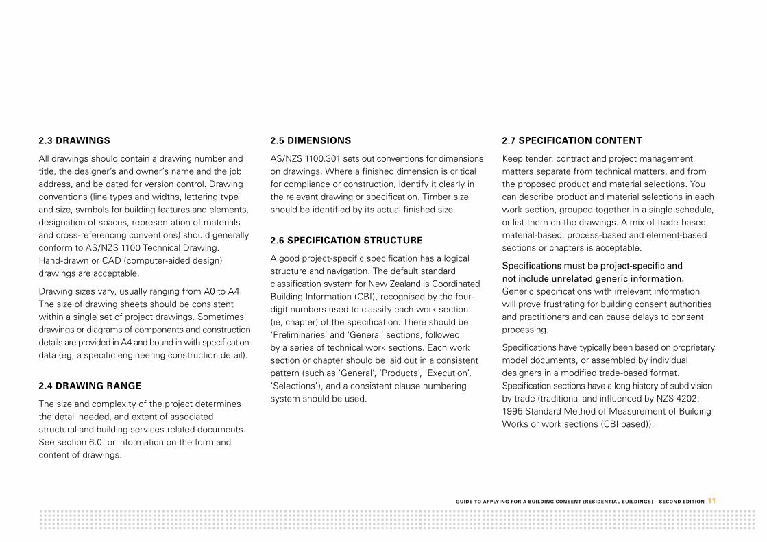
This section gives examples and brief explanations of consent drawings. Please note these are examples only.
• Siteplan• Locationplan• Foundationplan• Floorplan• Roofframingplan• Exteriorelevation• Sections• Constructiondetails• Door/windowschedule• Plumbinglayout/schematicplan• Electricalplan• Wetareadetails
Guidance is provided on the quality, content, form and type of information each drawing should include. The descriptions are not exhaustive but are typical of the information that should be shown.
Some of the recommended information is unrelated to the Building Code but will help the building consent authority determine whether the work complies or needs approval under other legislation, such as local bylaws or district plan requirements under the Resource Management Act. Such additional information, as well as Building Code related information, is shown in text boxes like this.

20 GuidE tO ApplyinG fOr A buildinG cOnSEnt ( rESidEntiAl buildinGS) – SEcOnd EditiOn
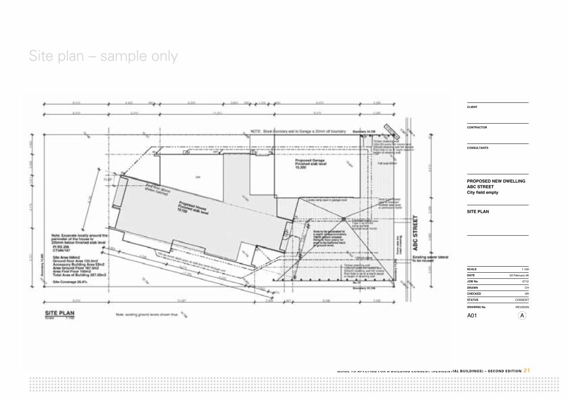
5.1 Site plan
The purpose of a site plan is to show the location of the proposed building work on the site in relation to adjoining properties.
drAwinG typE (nOtE 1)
rEcOmmEndEd ScAlE minimum rEcOmmEndEd dEtAil (nOtE 2)
Site plan (Note 3)
1:200 (Note 4) Legal description, legal boundaries and easements
North point
Building location, including dimensions in metres to boundaries, and boundary fire ratings
Spot levels or contours and site datum
Location of existing and new services (water, power, gas, stormwater, foul water) and method of disposal/discharge
Connection between services and network utility operators’ systems
Proposed/actual driveway, site finishes (hard and soft) with levels and falls
Excavation details (cut and fill) and retaining walls
Existing buildings and site features
Identify known natural hazards
Identify vehicle crossings
Additional informationWhen preparing the plan, check with the building consent authority and network utility operators for information on the location of existing services both to and across the site.Including calculations for site coverage on the site plan will help the territorial authority determine compliance with district plan requirements.
table notes
Note 1 Drawings may be combined.
Note 2 Requirements may differ where the building project is an alteration or addition to an existing building.
Note 3 For rural and/or larger sites a 1:500 (or 1:1000) location plan may be needed to confirm the site location. This is especially relevant where the distance to boundaries cannot be shown on the site plan due to the size of the property.
Note 4 A scale of 1:500 or 1:100 may be adequate.
GuidE tO ApplyinG fOr A buildinG cOnSEnt ( rESidEntiAl buildinGS) – SEcOnd EditiOn 21
Site plan – sample only
© THE DESIGNS CONTAINED ON THIS SHEET OF DRAWINGS ARE COPYRIGHT
CLIENT
CONTRACTOR
DRAWING No. REVISION
CONSULTANTS
DRAWN
CHECKED
SCALE
JOB No.
DATE
STATUS
CONTRACTOR SHALL VERIFY ALL DIMENSIONS ON SITE.
REVISIONS
0712
CH
KR
CONSENT
02 February 06
A01
PROPOSED NEW DWELLING
SITE PLAN
1:100
A
ABC STREETCity field empty
17,205
525
1,910390
4,740
3,270
4,780
1,600
200
2,80
0
200
1,95
917
0
6,13
0
3,29514,267 2,903 827 6,5966,310
5,72
14,17
51,01
12,05
91,92
0
6,310 5,013 11,210 8,370 3,295
3,32
53,09
22,28
06,17
020
6,310 4,433 580 6,200 2,600 580 1,230 600 8,370 3,295
15.00°
10.794
10.150
10.812
10.748
10.563
10.704
10.721
10.855
10.624
10.084 K
10.806
10.776
9.959 In
10.741
9.987 K
9.866 In10.565
dp
Boun
dary
14,
886
Boundary 34,198
Boundary 34,198
No 51
Area to be excavated to a depth of approximately10050 shown shaded.Refer to floor plans for area to be battered back to ground level.
dp
10.000 DatumNOTE: Block boundary wall to Garage is 20mm off boundary
dp
dp
Proposed GarageFinished slab level10300
dp
ABC
STRE
ET
Existing sewer lateralto be reused
DW
100 dia sewer
dp
dp
Locally ramp seal to garage door
Construct sumpType 1 as E1/ASsump surfacefinished level 10150
Area to be sealedrefer to floorplanfinished seal levelat perimeter 10200
Note: Excavate locally around the perimeter of the house to225mm below finished slab level
Fall seal 50mm
Boun
dary
14,
886
Form
new
4m
ro
ad c
ross
ing
vent
SITE PLANScale
First floor aboveshown hatched
Note: existing ground levels shown thus1:100
10.748
Timber retaining wall125x125 posts H4 treated and200x50 retaining wall H4 treatedPost hole to be at depth equal to height of retainng wall.
Timber retaining wall125x125 posts H4 treated and200x50 retaining wall H4 treatedPost hole to be at a depth equalto height of retaining wall
gt gt
gt
100 dia sewer stack goes up wall and vents through roof
Pt RS 206CT386/187
SIte Area 506m2Ground floor Area 135.5m2Accessory Building Area 52m2Area Ground Floor 187.5m2Area First Floor 100m2Total Area of Building 287.50m2
Site Coverage 26.8%
Proposed HouseFinished slab level10700

22 GuidE tO ApplyinG fOr A buildinG cOnSEnt ( rESidEntiAl buildinGS) – SEcOnd EditiOn
5.2 Location plan
A location plan is a high-level ‘bird’s eye view’ of the area surrounding the proposed building work. It shows the location of the proposed work in relation to adjoining streets or properties. These plans are particularly useful in rural or remote locations, or multi-unit residential complexes.
drAwinG typE (nOtE 1)
rEcOmmEndEd ScAlE minimum rEcOmmEndEd dEtAil (nOtE 2)
Location plan 1:500 (Note 3) Legal description, legal boundaries and easements
North point
Existing buildings and site features
Identify known natural hazards
Identify vehicle crossings
Additional informationWhere the property is located in a flood zone, confirm the relationship between the site datum and the minimum occupied floor level set by the territorial authority in the district plan.The distance to relevant boundaries can be added to the location plan, where this cannot be shown on the site plan, due to the size of the property.
table notes
Note 1 Drawings may be combined.
Note 2 Requirements may differ where the building project is an alteration or addition to an existing building.
Note 3 For rural and/or larger sites, a scale of 1:1000 or smaller may be needed to confirm the site location.

GUIDE TO APPLYING FOR A BUILDING CONSENT ( RESIDENTIAL BUILDINGS) – SECOND EDITION 23
Location plan – sample only
CONTRACTOR
A
JOB No.
CONSULTANTS
07123
STATUS
01 May 2010
SCALE
Construction
DRAWING No.
CHECKED
DRAWN
SITE PLANSITE LOCATION PLAN
CLIENT
DATE
A01REVISION
PROPOSED NEW DWELLINGABC STREET
N
57,000
10,3
0035
,000Lot XX DP YYY
Area approx: 1.1125haTotal Building (inc verandahs): 404m2Total site coverage: 3.63%
L1
S
T
R
EA
M
setout position to be confirmed by designerand owner prior to excavation of founds.
XXXX DRIVE
YYYY
DRI
VE
Location Plan 1:1000

24 GuidE tO ApplyinG fOr A buildinG cOnSEnt ( rESidEntiAl buildinGS) – SEcOnd EditiOn
5.3 Foundation plan
The foundation plan illustrates to the building consent authority and your building practitioners the foundation design you propose, and details its specific dimensions and construction requirements.
drAwinG typE (nOtE 1)
rEcOmmEndEd ScAlE minimum rEcOmmEndEd dEtAil (nOtE 2)
Foundation plan 1:100 (Note 3) Concrete slab dimensions and thickenings (where applicable)
Concrete slab reinforcing details and construction joints
Foundation walls
Pile layout with dimensions, pile type bearer sizes (including decks and pergolas)
Finished floor heights in relation to site datum
Sub-floor bracing layout
Sub-floor ventilation (or show on elevations)
Floor framing layout (optional) (Note 4)
Specific design foundations
Additional information
Where the property is located in a flood zone, confirm the relationship between the site datum and the minimum occupied floor level set by the territorial authority in the district plan.
If a registered engineer has designed the foundations, provide supporting information, including calculations, design assumptions (eg, soil bearing) and possibly a producer statement for design. Identify details of inspections and tests to be carried out by the design engineer on the building consent application form under the heading ‘Proposed owner inspections’.
table notes
Note 1 Drawings may be combined.
Note 2 Requirements may differ where the building project is an alteration or addition to an existing building.
Note 3 A scale of 1:50 may be needed where foundations are relatively complex.
Note 4 Provided it is clear as to what is required, it may not be necessary to show each and every floor joist.

GuidE tO ApplyinG fOr A buildinG cOnSEnt ( rESidEntiAl buildinGS) – SEcOnd EditiOn 25
Foundation plan – sample only
600
1,30
01,
300
1,30
01,
300
1,30
01,
125
200
740 1,650 1,650 1,650 1,650 1,360 1,600 1,650 1,650 1,650 1,650 310 190
150x50 joists @ 450c/c
100
190 1,050 3,150
190
3,01
024
02,
864
190
800
4,60
070
019
0
190
210
190
4,21
019
03,
010
190
4,11
019
061
019
0
5,800 240 810 190 7,910 190 6,910 190 3,510 190 5,000
1,900 190 810 190 1,810190
810 190 2,610 190 10,110 190 2,810 190 4,510 190 3,810 190
1,050 1,050 1,050 550500
1,050 950
H3.2
H3.1
H1.1
H1.2
H5
100x50 Floor Joists @ 450crs
block joists on mitre for decking
Foundation Plan
Timber 125x125 H5 Piles @ 1300crs
1:100
100x50 Deck Joists @ 450crs
Bolt bearer to block wallM12 bolts at 1000c/c
Jois
ts to
can
tilev
er
planter planter
Scale
Bolt bearer to block wallM12 bolts at 1000c/c
Joists fixed to 100 x 50 plate bolted to top of block wall M12bolts at 1400c/c
Framing protected from the weather, above ground with the possibility of exposure to moisture.
Skillion roof above10º framing with lined soffitsExterior walls protected from the weatherWall framingSubfloor framing except piles
Framing exposed to intermittent moisture, above ground but protected from the weather by an approvedpaint system or cladding.
Wall and floor framing to at risk wet areasRoof framing below 10ºExterior painted posts and beamsEnclosed lintels and posts supporting enclosed balconies.Enclosed balcony ply and joists.Balustrade framingCavity battens
Framing exposed to the weather above ground with a risk of trapped water.
External rafters and beams.Timber slatted decking joists and bearersFence pailings and rails not in contact with ground
BASEMENT
Framing protected from the weather and above ground (not sub-floor framing)
Roof and ceiling framingRoof trusses / purlinsLow risk interior wall framingIntermediate interior floor framing
SCHEDULE OF TIMBER TREATMENT
Joists to cantilever
100x50 H3.2 Deck Joists @ 450crs
Timber 125x125 H5 Piles @ 1300crs
GARAGE
Timber in contact with the ground
Piles
Prestressed rib floor over garage refer to Engineers drawings for details of ribs concrete slab and reinforcing.
100 concrete floor slab reinforced with HRC 665 meshon polythene dpc on sand blinding on hardfillto Garage floor and basement.
100x75 bearer secured to block wall with galv bracket
100 concrete floor slab reinforced with HRC 665 meshon polythene dpc on sand blinding on hardfill.
CONTRACTOR
JOB No.
CONSULTANTS
07123
STATUS
28 February 06
SCALE
Construction
DRAWING No.
CHECKED
DRAWN
CLIENT
DATE
REVISION
© THE DESIGNS CONTAINED ON THIS SHEET OF DRAWINGS ARE COPYRIGHT.
CONTRACTOR SHALL VERIFY ALL DIMENSIONS ON SITE
REVISIONS
PROPOSED NEW DWELLING123 ABC STREET
Foundation and Sub floorFraming Plan
04 X
100 1,500 100 3,000 100 1,600 100 700 100 2,100 100
2,368 5,400 100 900 100 2,900 100
2,700
2,700
100 1,500 100 900 1,800 600 1,400 100 1,700100
1,100 100 2,700
400
900
5,60
02,
300
100
900
100
2,20
010
02,
800
100
1,30
010
090
010
04,
500
80020
010
0 1,20
010
090
02,
300
100
1,35
010
01,
350
400
900
5,70
070
090
090
050
01,
100
1,00
050
02,
900
4,50
015
,500
2,27
0
1,30
05,
700
5,60
02,
900
100 4,800 100 1,400 100 5,600 100
4,50
030
07,
500
1,34
52,
459
3,89
62,
270
7,900 12,200 200
2,330 1,300 2,400 500400 400
1,100 400 5,700 200
7,900 12,200
900 100 900 100 2,500 100 1,800 5,800
400
900
1,00
010
03,
400
100
3,59
710
02,
003
3,90
0
400
900
1,20
035
01,
075
350
1,07
535
01,
048
350
1,05
035
01,
100
2,00
33,
900
15,5
00
4,200 400 1,500 400 5,700
4,900 100 1,400 100 5,700
300
100
5,40
010
01,
900
100
3,60
010
01,
700
100
2,00
010
0
R 6,777
30.00°
FIRST FLOOR PLAN1:100Scale
BOUNDARY 3.20m 14˚30'30"
S5
BOU
ND
ARY
22.2
7m
284˚
30'3
0"
53˚ R
eces
sion
BOUNDARY 20.30m 14˚30'30"
BOU
ND
ARY
20.2
7m
284˚
30'3
0"
33˚ R
eces
sion
A - B
C -
D
GTW2
W20
B BRACING UNITS
1:100
ROW
BOU
ND
ARY
39.1
m
284˚
30'3
0"
33˚ R
eces
sion
Scale
LAUNDRYHWC
TUB
4
HT
DINING
KITCHEN
BATHROOM
D3
D4
D6
D8
D11
D12
D13
D14
D18
D19
D20
D21
D22
CPD
D1 W1
W5
1
BED 3
W9
GARAGE
pantry
STORE
2PASS
AGE
1
3
C BRACE TYPE
STAIR
WB 3
WB 2
D2
ENTRY
D5
MV
D16
unit
by o
wne
rW4
W7
TOILET
D15
2/15
0x50
22 ABC STREET
open
ings
wal
ls
exte
rior w
alls
over
all
wal
ls
BED 2
W10
HT
dp
dp
HTdp dp
dp
dp
W6
3S1
S44
3S1
WASH
S44
A - BC - D
A - B
C -
D
D9
W3
4567
8
DRY
D17
D10
frig
W8
200 dia. PVC columns with concrete bases and caps. Timber pergola over.
Stamped concrete terrace
BOUNDARY 18.30m 14˚30'30" 43˚ Recession
Dotted line of slab thickening below load bearing wall as NZS 3604LIVING
walls
openings
A - BC - D
walls
walls
A - BC - D
Bracing Lines
A C DB E
M
N
O
P
Q
GROUND FLOOR PLAN
A - BC - D
A - BC - D
A - BC - D
A - B
C -
D
A - B
C -
D
BRACING KEY
D BRACE LENGTH
A BRACE NO.
A - B
C -
D
A - B
C -
D
A - B
C -
D
A - BC - D
A - BC - D
STREET ADDRESS ABC STREETDP 71216LOT 71SITE AREA 450 m2BUILDINGFLOORAREA 155.7m2FIRST FLOORAREA 46.2 m2SITE COVERAGE 34.6 %
exterior walls
overall
overall
Smokedetector
S44
Dotted line of coved monopitch ceiling. Do not line around valley
A - BC - D
Q
O
D23
W17
W18W19
D7
1234567
VOID
OPEN
exterior walls
W11
dp
dp
fall
PASSAGE 2
DECK
S54
wal
ls
S44
N
P
STAIR
13 148 9 10 11 12
robe
han
ging
D24
A C DB
M
walls
over
all
open
ings
wal
ls
robe
han
ging
Heater
W13
ENSUITE
D25access door to roof space
3S1
3S1
DRESSW12
access door to roof space
walls
Bracing Lines
A - BC - D
A - B
C -
D
A - B
C -
D
A - B
C -
D
A - BC - D
A - B
C -
D
A - BC - D
W15
W16
W14
Smokedetector
CONTRACTOR
JOB No.
CONSULTANTS
STATUS
28 February 06
SCALE
DRAWING No.
CHECKED
DRAWN
CLIENT
DATE
REVISION
PROPOSED NEW DWELLINGABC STREET
© THE DESIGNS CONTAINED ON THIS SHEET OF DRAWINGS ARE COPYRIGHT.
CONTRACTOR SHALL VERIFY ALL DIMENSIONS ON SITE
REVISIONS
FLOOR PLANS
A02 A
0666
Consent
A - BC - D

26 GuidE tO ApplyinG fOr A buildinG cOnSEnt ( rESidEntiAl buildinGS) – SEcOnd EditiOn
5.4 Roof framing plan
The roof framing plan shows the building consent authority and your building practitioners the proposed roof design and type of construction, whether it is a framed roof using rafters or a trussed roof. It can include:
• aplanlayoutofroofframingmembersandseatingoftrussesandbeams• drawingsoftimbertrusses,andproprietarytimberandtimber/steelmembers.
drAwinG typE (nOtE 1)
rEcOmmEndEd ScAlE minimum rEcOmmEndEd dEtAil (nOtE 2)
Roof framing plan 1:100 (Note 3) Structural roof members identified
Sizes of timber (framed rafters) and timber species (eg Douglas fir, radiata pine)
Hold down and fixing details for structural roof members (also for lintels and trimmer studs)
Plane bracing and space bracing details
Point loads
Complex junctions
Note on the plan whether purlins or battens are used. Include:
• sizes• spans• spacings• connections(forwindzone)• typeoftimber• roofingmaterial.
Additional information
Where roof framing is designed by a registered engineer, supporting information should be provided, including design calculations, design assumptions and possibly a producer statement design.
Identify details of inspections to be carried out by the design engineer on the building consent application under the heading ‘Proposed owner inspections’.
If using a trussed roof, it is unnecessary to provide truss design calculations produced by truss manufacturers’ truss design programmes. See section 8.3 for more information.
table notes
Note 1 Drawings may be combined.
Note 2 Requirements may differ where the building project is an alteration or addition to an existing building.
Note 3 A scale of 1:50 may be needed where roof forms are relatively complex.

GuidE tO ApplyinG fOr A buildinG cOnSEnt ( rESidEntiAl buildinGS) – SEcOnd EditiOn 27
Roof framing plan – sample only
Trus
sed
Gab
le R
oof
Flat
Roo
fSk
illion
Roo
f
240x45 H1.2 VSG8 Pinus Radiatarafters @ 600crs. max.
Steel ridge beam designed bystructural engineer.
18mm H3.2 plywood on tapered packersto fall on 140x45 H3.1 VSG8 PinusRadiata rafters @ 400crs.
Steel PFC lintels. Designed byStructural Engineer.
Proprietary metal "Strapbrace"diagonal roof plane bracing. Fixed inaccordance with manufacturersinstallation instructions.Stra
pbrac
e Strapbrace
StrapbraceStra
pbrac
e
StrapbraceStrapb
race
StrapbraceStrapbrace
StrapbraceStrapb
race
StrapbraceStrapb
race
NOTESWindzone: XXXXRoof Cladding: XXXX
Rafters:Rafter fixings to be as Table 10.1, NZS 3604.
Purlins:Note: Not shown on plans for clarity.Purlins shall be sized as Tables 10.10 and 10.11,NZS 3604.Purlin fixings to be as Tables 10.10 and 10.11, NZS3604.Purlin spacings shall be as required by roofcladding manufacturer.
Tile Battens:Note: Not shown on plans for clarity.Tile battens shall be sized as Table 10.12, NZS3604.Tile batten spacings shall be as required by roofcladding manufacturer.
Roof Bracing:Roof bracing as per Table 10.16 NZS 3604.Roof space diagonal bracing (where required) asper Fig. 10.12 NZS 3604.
Engineered timber trusses @ 900crs. To beinstalled as per manufacturers instructions.Fixings to be as rafter fixings, NZS 3604.
1:100Roof Framing Plan
CONTRACTOR
B
JOB No.
CONSULTANTS
07123
STATUS
01 May 2010
SCALE
Construction
DRAWING No.
CHECKED
DRAWN
ROOF FRAMING LAYOUT
CLIENT
DATE
A05REVISION
PROPOSED NEW DWELLINGABC STREET
© THE DESIGNS CONTAINED ON THIS SHEET OF DRAWINGS ARE COPYRIGHT.
1: 100
THE CONTRACTOR SHALL VERIFY ALL DIMENSIONS ON SITE.
nOtESWindzone: XXXXRoof Cladding: XXXX
rafters:Rafter fixings to be as Table 10.1, NZS 3604
purlins:Note: Not shown on plans for clarity.Purlins shall be 70 x 45, maximum span 900 in a High Wind Zone with a maximum spacing of 1200 mm.Purlin fixings to be 2/100 x 3.75 skewed nails plus one wiredog.
tile battens:Note: Not shown on plans for clarity.Tile battens shall be 50 x 40, maximum span 900 with maximum spacing of 400 mm.Tile batten spacings shall be as required by roof cladding manufacturer.
roof bracing:Roof bracing as per Table 10.16 NZS 3604. Roof space diagonal bracing (where required) as per Fig 10.12 NZS 3604.

28 GuidE tO ApplyinG fOr A buildinG cOnSEnt ( rESidEntiAl buildinGS) – SEcOnd EditiOn
5.5 Floor plans
Floor plans provide details of room types and sizes, the layout and location of external and internal elements, and the location of all fixtures and fittings.
drAwinG typE (nOtE 1)
rEcOmmEndEd ScAlE minimum rEcOmmEndEd dEtAil (nOtE 2)
Floor plan(s) 1:50 (Note 3) Floor levels relative to the site datum
Overall dimensions of walls and other structural elements
Internal dimensions of rooms and room identification
Bracing layout or reference to a schedule elsewhere
Lintel sizes or reference to a schedule elsewhere
Window and door locations, door/window numbers and plan dimensions
Special wall constructions (sound, fire, moisture control)
Room layouts and location of all internal fixtures and fittings
Position of sanitary fixtures and appliances
Type of hot water system proposed
Staircase layouts
Cross-section references
References to detailed drawings
Outline of roof, or pergola overhangs
Additional information
If floor plans are complex, use a separate key plan with the critical structural information, such as bracing elements and lintels, to avoid cluttering the floor plans.
Show any installations related to the building consent, such as smoke alarms.
If the building work is an addition or alteration to an existing building, the floor plan should clearly distinguish between the proposed new and the existing building work.
table notes:
Note 1 Drawings may be combined.
Note 2 Requirements may differ where the building project is an alteration or addition to an existing building.
Note 3 A scale of 1:100 may be adequate for a simple project. A separate plan must be provided for each building level. If the lower floor is timber framed, use a foundation plan to clarify the foundation layout. See section 5.3.

GuidE tO ApplyinG fOr A buildinG cOnSEnt ( rESidEntiAl buildinGS) – SEcOnd EditiOn 29
Floor plans – sample only
100 1,500 100 3,000 100 1,600 100 700 100 2,100 100
2,368 5,400 100 900 100 2,900 100
2,700
2,700
100 1,500 100 900 1,800 600 1,400 100 1,700100
1,100 100 2,700
400
900
5,60
02,
300
100
900
100
2,20
010
02,
800
100
1,30
010
090
010
04,
500
80020
010
0 1,20
010
090
02,
300
100
1,35
010
01,
350
400
900
5,70
070
090
090
050
01,
100
1,00
050
02,
900
4,50
015
,500
2,27
0
1,30
05,
700
5,60
02,
900
100 4,800 100 1,400 100 5,600 100
4,50
030
07,
500
1,34
52,
459
3,89
62,
270
7,900 12,200 200
2,330 1,300 2,400 500400 400
1,100 400 5,700 200
7,900 12,200
900 100 900 100 2,500 100 1,800 5,800
400
900
1,00
010
03,
400
100
3,59
710
02,
003
3,90
0
400
900
1,20
035
01,
075
350
1,07
535
01,
048
350
1,05
035
01,
100
2,00
33,
900
15,5
00
4,200 400 1,500 400 5,700
4,900 100 1,400 100 5,700
300
100
5,40
010
01,
900
100
3,60
010
01,
700
100
2,00
010
0
R 6,777
30.00°
FIRST FLOOR PLAN1:100Scale
BOUNDARY 3.20m 14˚30'30"
S5
BOU
ND
ARY
22.2
7m
284˚
30'3
0"
53˚ R
eces
sion
BOUNDARY 20.30m 14˚30'30"
BOU
ND
ARY
20.2
7m
284˚
30'3
0"
33˚ R
eces
sion
A - B
C -
D
GTW2
W20
B BRACING UNITS
1:100
ROW
BOU
ND
ARY
39.1
m
284˚
30'3
0"
33˚ R
eces
sion
Scale
LAUNDRYHWC
TUB
4
HT
DINING
KITCHEN
BATHROOM
D3
D4
D6
D8
D11
D12
D13
D14
D18
D19
D20
D21
D22
CPD
D1 W1
W5
1
BED 3
W9
GARAGE
pantry
STORE
2PASS
AGE
1
3
C BRACE TYPE
STAIR
WB 3
WB 2
D2
ENTRY
D5
MV
D16
unit
by o
wne
rW4
W7
TOILET
D15
2/15
0x50
22 ABC STREETop
enin
gs
wal
ls
exte
rior w
alls
over
all
wal
ls
BED 2
W10
HT
dp
dp
HTdp dp
dp
dp
W6
3S1
S44
3S1
WASH
S44
A - BC - D
A - B
C -
D
D9
W3
4567
8
DRY
D17
D10
frig
W8
200 dia. PVC columns with concrete bases and caps. Timber pergola over.
Stamped concrete terrace
BOUNDARY 18.30m 14˚30'30" 43˚ Recession
Dotted line of slab thickening below load bearing wall as NZS 3604LIVING
walls
openings
A - BC - D
walls
walls
A - BC - D
Bracing Lines
A C DB E
M
N
O
P
Q
GROUND FLOOR PLAN
A - BC - D
A - BC - D
A - BC - D
A - B
C -
D
A - B
C -
DBRACING KEY
D BRACE LENGTH
A BRACE NO.
A - B
C -
D
A - B
C -
D
A - B
C -
D
A - BC - D
A - BC - D
STREET ADDRESS ABC STREETDP 71216LOT 71SITE AREA 450 m2BUILDINGFLOORAREA 155.7m2FIRST FLOORAREA 46.2 m2SITE COVERAGE 34.6 %
exterior walls
overall
overall
Smokedetector
S44
Dotted line of coved monopitch ceiling. Do not line around valley
A - BC - D
Q
O
D23
W17
W18W19
D7
1234567
VOID
OPEN
exterior walls
W11
dp
dp
fall
PASSAGE 2
DECK
S54
wal
ls
S44
N
P
STAIR
13 148 9 10 11 12
robe
han
ging
D24
A C DB
M
walls
over
all
open
ings
wal
ls
robe
han
ging
Heater
W13
ENSUITE
D25access door to roof space
3S1
3S1
DRESSW12
access door to roof space
walls
Bracing Lines
A - BC - D
A - B
C -
D
A - B
C -
D
A - B
C -
D
A - BC - D
A - B
C -
D
A - BC - D
W15
W16
W14
Smokedetector
CONTRACTOR
JOB No.
CONSULTANTS
STATUS
28 February 06
SCALE
DRAWING No.
CHECKED
DRAWN
CLIENT
DATE
REVISION
PROPOSED NEW DWELLINGABC STREET
© THE DESIGNS CONTAINED ON THIS SHEET OF DRAWINGS ARE COPYRIGHT.
CONTRACTOR SHALL VERIFY ALL DIMENSIONS ON SITE
REVISIONS
FLOOR PLANS
A02 A
0666
Consent
A - BC - D
100 1,500 100 3,000 100 1,600 100 700 100 2,100 100
2,368 5,400 100 900 100 2,900 100
2,700
2,700
100 1,500 100 900 1,800 600 1,400 100 1,700100
1,100 100 2,700
400
900
5,60
02,
300
100
900
100
2,20
010
02,
800
100
1,30
010
090
010
04,
500
80020
010
0 1,20
010
090
02,
300
100
1,35
010
01,
350
400
900
5,70
070
090
090
050
01,
100
1,00
050
02,
900
4,50
015
,500
2,27
0
1,30
05,
700
5,60
02,
900
100 4,800 100 1,400 100 5,600 100
4,50
030
07,
500
1,34
52,
459
3,89
62,
270
7,900 12,200 200
2,330 1,300 2,400 500400 400
1,100 400 5,700 200
7,900 12,200
900 100 900 100 2,500 100 1,800 5,800
400
900
1,00
010
03,
400
100
3,59
710
02,
003
3,90
0
400
900
1,20
035
01,
075
350
1,07
535
01,
048
350
1,05
035
01,
100
2,00
33,
900
15,5
00
4,200 400 1,500 400 5,700
4,900 100 1,400 100 5,700
300
100
5,40
010
01,
900
100
3,60
010
01,
700
100
2,00
010
0
R 6,777
30.00°
FIRST FLOOR PLAN1:100Scale
BOUNDARY 3.20m 14˚30'30"
S5
BOU
ND
ARY
22.2
7m
284˚
30'3
0"
53˚ R
eces
sion
BOUNDARY 20.30m 14˚30'30"
BOU
ND
ARY
20.2
7m
284˚
30'3
0"
33˚ R
eces
sion
A - B
C -
D
GTW2
W20
B BRACING UNITS
1:100
ROW
BOU
ND
ARY
39.1
m
284˚
30'3
0"
33˚ R
eces
sion
Scale
LAUNDRYHWC
TUB
4
HT
DINING
KITCHEN
BATHROOM
D3
D4
D6
D8
D11
D12
D13
D14
D18
D19
D20
D21
D22
CPD
D1 W1
W5
1
BED 3
W9
GARAGE
pantry
STORE
2PASS
AGE
1
3
C BRACE TYPE
STAIR
WB 3
WB 2
D2
ENTRY
D5
MV
D16
unit
by o
wne
rW4
W7
TOILET
D15
2/15
0x50
22 ABC STREET
open
ings
wal
ls
exte
rior w
alls
over
all
wal
ls
BED 2
W10
HT
dp
dp
HTdp dp
dp
dp
W6
3S1
S44
3S1
WASH
S44
A - BC - D
A - B
C -
D
D9
W3
4567
8
DRY
D17
D10
frig
W8
200 dia. PVC columns with concrete bases and caps. Timber pergola over.
Stamped concrete terrace
BOUNDARY 18.30m 14˚30'30" 43˚ Recession
Dotted line of slab thickening below load bearing wall as NZS 3604LIVING
walls
openings
A - BC - D
walls
walls
A - BC - D
Bracing Lines
A C DB E
M
N
O
P
Q
GROUND FLOOR PLAN
A - BC - D
A - BC - D
A - BC - D
A - B
C -
D
A - B
C -
D
BRACING KEY
D BRACE LENGTH
A BRACE NO.
A - B
C -
D
A - B
C -
D
A - B
C -
D
A - BC - D
A - BC - D
STREET ADDRESS ABC STREETDP 71216LOT 71SITE AREA 450 m2BUILDINGFLOORAREA 155.7m2FIRST FLOORAREA 46.2 m2SITE COVERAGE 34.6 %
exterior walls
overall
overall
Smokedetector
S44
Dotted line of coved monopitch ceiling. Do not line around valley
A - BC - D
Q
O
D23
W17
W18W19
D7
1234567
VOID
OPEN
exterior walls
W11
dp
dp
fall
PASSAGE 2
DECK
S54
wal
ls
S44
N
P
STAIR
13 148 9 10 11 12
robe
han
ging
D24
A C DB
M
walls
over
all
open
ings
wal
ls
robe
han
ging
Heater
W13
ENSUITE
D25access door to roof space
3S1
3S1
DRESSW12
access door to roof space
walls
Bracing Lines
A - BC - D
A - B
C -
D
A - B
C -
D
A - B
C -
D
A - BC - D
A - B
C -
D
A - BC - D
W15
W16
W14
Smokedetector
CONTRACTOR
JOB No.
CONSULTANTS
STATUS
28 February 06
SCALE
DRAWING No.
CHECKED
DRAWN
CLIENT
DATE
REVISION
PROPOSED NEW DWELLINGABC STREET
© THE DESIGNS CONTAINED ON THIS SHEET OF DRAWINGS ARE COPYRIGHT.
CONTRACTOR SHALL VERIFY ALL DIMENSIONS ON SITE
REVISIONS
FLOOR PLANS
A02 A
0666
Consent
A - BC - D

30 GuidE tO ApplyinG fOr A buildinG cOnSEnt ( rESidEntiAl buildinGS) – SEcOnd EditiOn
5.6 Exterior elevations
Exterior elevations show the overall shape, form and size of the proposed building in relation to any adjoining boundaries.
drAwinG typE (nOtE 1)
rEcOmmEndEd ScAlE minimum rEcOmmEndEd dEtAil (nOtE 2)
Elevations
1:100 (Note 3)
All exterior elevations of the building
Relative levels, overall height of dwelling
Windows, doors and other openings, indicating opening type and direction
Cladding types
Roofing types, roof shapes and overhangs
Exterior decks, stairs, balustrades
Skylights, chimneys and other openings through walls and roof
Gutter, downpipe and vent locations
Location of construction joints in claddings
References to detailed drawings
Reference to risk matrix (Note 4)
Additional information
Extending ground lines through to adjacent boundaries, showing maximum height to boundary angles (sunlight access planes), will help the territorial authority confirm compliance with planning requirements.
table notes
Note 1 Drawings may be combined.
Note 2 Requirements may differ where the building project is an alteration or addition to an existing building.
Note 3 Increase to 1:50 minimum scale where exterior openings are not scheduled elsewhere.
Note 4 For more information on using the risk matrix, visit www.dbh.govt.nz/UserFiles/File/Publications/WHRS/pdf/e2-riskmatrix.pdf

GUIDE TO APPLYING FOR A BUILDING CONSENT ( RESIDENTIAL BUILDINGS) – SECOND EDITION 31
Elevations – sample only
CONTRACTOR
B
JOB No.
CONSULTANTS
07123
STATUS
01 May 2010
SCALE
Construction
DRAWING No.
CHECKED
DRAWN
ELEVATIONS
CLIENT
DATE
A05REVISION
PROPOSED NEW DWELLINGABC STREET

32 GuidE tO ApplyinG fOr A buildinG cOnSEnt ( rESidEntiAl buildinGS) – SEcOnd EditiOn
5.7 Sections
Sections show all vertical and horizontal building elements and their relationship to the ground, floors, ceilings and roofs. They also detail structural framing and other construction elements.
drAwinG typE (nOtE 1)
rEcOmmEndEd ScAlE minimum rEcOmmEndEd dEtAil (nOtE 2)
Cross-sections (Note 3) 1:50 (Note 4) Ground levels and levels relative to site datum
Wall heights
Window and door height dimensions
Framing sizes and treatments (or in the specification) (Note 5)
Construction details (eg, wall and floor linings)
Roof and ceiling pitches
Location of staircases, decks and balustrades
Floor slopes
Location of details
Additional information
Sections and details can be combined on the same drawing. This can improve clarity, especially if details are shown in their relative position to an accompanying cross-section.
table notes
Note 1 Drawings may be combined.
Note 2 Requirements may differ where the building project is an alteration or addition to an existing building.
Note 3 Cross-sections must show all vertical relationships. Location of cross-sections should be shown on floor plans.
Note 4 A scale of 1:20 may be used.
Note 5 Timber grades may be identified on the drawings or in the specification.

GUIDE TO APPLYING FOR A BUILDING CONSENT ( RESIDENTIAL BUILDINGS) – SECOND EDITION 33
Sections – sample only
CONTRACTOR
B
JOB No.
CONSULTANTS
07123
STATUS
01 May 2010
SCALE
Construction
DRAWING No.
CHECKED
DRAWN
SECTION A
CLIENT
DATE
A0 7REVISION
PROPOSED NEW DWELLINGABC STREET
© THE DESIGNS CONTAINED ON THIS SHEET OF DRAWINGS ARE COPYRIGHT.
THE CONTRACTOR SHALL VERIFY ALL DIMENSIONS ON SITE.
SECTION B
2,76
0
450
240300
525
200
2,46
0
+13,030
+10,000+9,800
22.50°
22.50°
C1
C2
C10
C3
C11
C4
C12
C5
C6
C15
C9
C14
F4
C7
C8
Family
Bedroom 3Bath.Bedroom 4
PassageBathroom Dining/Living
Section A1:50Scale
2,100
R3.6 155mminsulation betweenfloors. 2,300300x100 lintel
Solid blocking
Nail plate roof trusses to manufacturers design.Manufacturer to submit design certificate to BCAbefore construction is commenced.
D05
2,76
0
2,46
0
450450
300
+9,800
+13,030
+10,000
22.50°
C1
C8
C2
C3
C10
C11
C5
C12
C6
C14
C7
C9
C15
C4
Passage Dining/Living
300x100 lintel
Passage
1:50ScaleSection B
8
1
16
Metal balustrade,see sheet 5 fordetails.
Nail plate roof trusses to manufacturers design.Manufacturer to submit design certificate to BCAbefore construction is commenced.
Rimu stringer &custonwood treads &risers. Carpet finish.
250 Treads189 Risers
C1
C2
C3
C5
C6
C7
C8
C13
C14
C15
C9
C10
C11
C12
C4
250x50 floor joists at 400 crs, solid blocking atperimeter, under wall plates & mid spans over3.6m(ie blocking at1.800 crs)
2-D16 rods & R10 ties @ 600crs.
20mm Particle board flooring
100mm concrete slab, reinforced with HRC 665mesh 50 mm H grade polystyrene insulation on0.25mm black polythene DPC, 20mm washedrounds & compacted hardfill.
Colorsteel Corr. roofing, self supporting B.P.75x50 purlins @ 800crs. Secure second nail fromtop & bottom purlins with two zed nails.
Rool trusses @ 900crs design bymanufacturer. Top plate uplift fixing accordingtoNZS 3604 & truss loadings. Min fixing one zednail per truss fixing.
Colorsteel fascia spouting on concealedbrackets @ 900 crs.
75mm Panel- Veneer fixed to H3.1 battensover building paperApproved plaster render.
Powder Coated aluminium windows treatedtimber reveals, double glazed.
90mm fibre glass wall insulation R2.6.
155mm fibre glass ceiling insulation R3.6.
Colorsteel round down pipes. 65Dia
4.75mm fibre cement soffit lining.
10mm plasterboard screw fixed across 75x40battens @ 450crs on all ceilings..
KEY NOTES
100x50 studs @ 600crs. Secure external wall bottomplates with M12 bolts @ 1400crs max. (Alternativelyuse bottom plate anchor & concrete nails @ 900crs) &Ramset fasteners to other walls @ 900crs. All bracedwalls to have M12 bolts at each end of brace.
1.0mm rubber membrane over 18mm H3treated plywood on H3.1 150x50 treatedpurlins @ 600crs, dwang @ 800crs
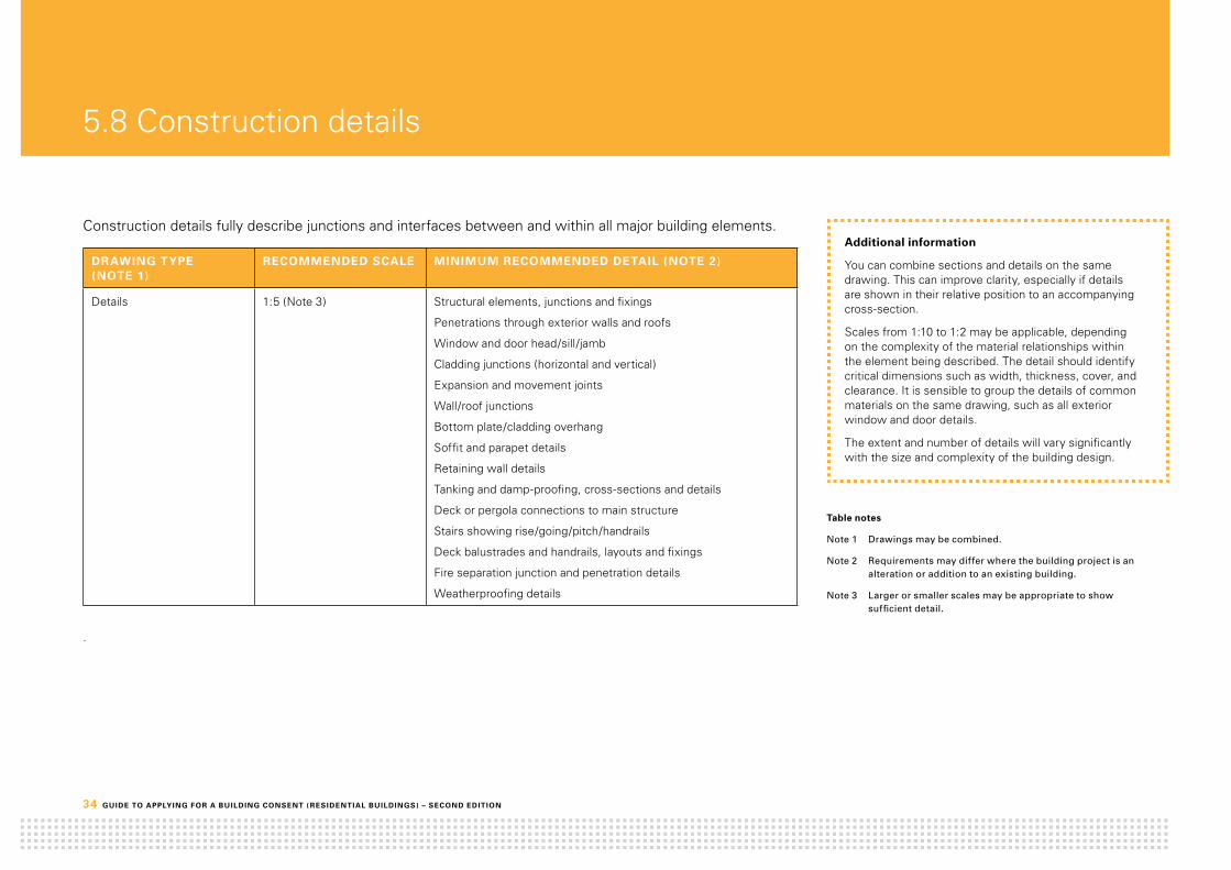
34 GuidE tO ApplyinG fOr A buildinG cOnSEnt ( rESidEntiAl buildinGS) – SEcOnd EditiOn
5.8 Construction details
Construction details fully describe junctions and interfaces between and within all major building elements.
drAwinG typE (nOtE 1)
rEcOmmEndEd ScAlE minimum rEcOmmEndEd dEtAil (nOtE 2)
Details 1:5 (Note 3) Structural elements, junctions and fixings
Penetrations through exterior walls and roofs
Window and door head/sill/jamb
Cladding junctions (horizontal and vertical)
Expansion and movement joints
Wall/roof junctions
Bottom plate/cladding overhang
Soffit and parapet details
Retaining wall details
Tanking and damp-proofing, cross-sections and details
Deck or pergola connections to main structure
Stairs showing rise/going/pitch/handrails
Deck balustrades and handrails, layouts and fixings
Fire separation junction and penetration details
Weatherproofing details
.
Additional information
You can combine sections and details on the same drawing. This can improve clarity, especially if details are shown in their relative position to an accompanying cross-section.
Scales from 1:10 to 1:2 may be applicable, depending on the complexity of the material relationships within the element being described. The detail should identify critical dimensions such as width, thickness, cover, and clearance. It is sensible to group the details of common materials on the same drawing, such as all exterior window and door details.
The extent and number of details will vary significantly with the size and complexity of the building design.
table notes
Note 1 Drawings may be combined.
Note 2 Requirements may differ where the building project is an alteration or addition to an existing building.
Note 3 Larger or smaller scales may be appropriate to show sufficient detail.

GuidE tO ApplyinG fOr A buildinG cOnSEnt ( rESidEntiAl buildinGS) – SEcOnd EditiOn 35
Construction details – sample only
75 70
200
min
min
5° fall
min
rockcote integra plaster render system on20x45 H1.2 MSG8 radiata cavity battens onthermakraft cover-up building paper on90x45 radiata framing @ 600crs.insulate with R2.8 pink batts ultra wall& line with 10mm GIB board.
folded colorsteel apron flashing.
continue building underlay up wall to top ofapron flashing.
folded colorsteel capping flashingpre drill holes before screw fixing.
dimond veedek roofing140x45 H1.2 MSG8 radiata purlins @ 800crs(on edge) on 240x63 hySPAN rafters @ 450crs.Second purlin from top & bottom to befixed with 1-nail & 1-screw all others 2 nails.
stop end to dimond veedek roofing.
Building paper over sloped H3.1 PinusRadiata timber packer. 5° slope.
dimond veedek roofing140x45 H1.2 MSG8 radiata purlins @ 800crs(on edge) on 240x63 hySPAN rafters @ 450crs.Second purlin from top & bottom to befixed with 1-nail & 1-screw all others 2 nails.
45x45 H3.2 MSG8 radiata fillet.
1.5mm grey butynol on18mm H3.2 CCA treated constructionplywood on 90x45 H3.1 MSG8 Pinus Radiatablocking @ 400crs to create fall.
lowest point of gutter dashed.check top of rafter to suit fall of gutter.
3575
200min
min
min
folded coloursteel apron flashing. Sized inaccordance with table 7 E2/AS1 NZBC
25mm wide radiata cant strip. thicknessto suit selected weatherboards.
jh linea weatherboards on20x45 H3.1 MSG8 radiata cavity battens onthermakraft cover-up building paper on140x45 H1.2 MSG8 radiata framing @ 600crs.
building paper to wrap over top of apron flashing.
thermakraft 215 building underlay undercorrugated iron roofing to wrap up wall &finish at top of apron flashing.
jh uPVC vent strip. mitre at corners. drainholes are sufficient to achieve ventilationopenings of 1000mm² per linea metre.
140x45 H1.2 MSG8 solid blocking behind flashing.
45x45 H3.2 MSG8 radiata fillet.
colorsteel corrugated iron longrun roofing onself supporting thermakraft 215 buildingunderlay on 70x45 radiata purlins ongangnail trusses @ 900crs.Second purlin from top & bottom to befixed with 1-nail & 1-screw all others 2 nails.
1.5mm grey butynol on18mm H3.2 CCA treated constructionplywood on 90x45 H3.1 MSG8 Pinua Radiatablocking @ 400crs (on edge) on 90x45H3.1 MSG8 Pinus Radiata rafters @ 900crs.
2,10
0ce
iling
heig
ht.
continue butynol over first purlin.
13mm GIB board onsuspended RONDO ceiling battens.insulate with 90mm R2.8 pink batts wall.
1.5mm grey butynol on18mm H3.2 CCA treated construction plywoodon H3.1 Pinus Radiata blocking @ 400crs (to create 1.5° fall) on90x45 H3.1MSG8 radiata joists @ 900crs.
4.5mm jh hardiflex soffit lining.
Rockcote Integra plaster render system on51mm integra PMV panel on20x40mm H3.1 MSG8 radiata cavity battens.
Detail flashing tape dressed over butynol
anodised, double glazed aluminium doorjoinery with H3.2 timber reveals.
building paper dressed into opening withflexible flashing detail tape to corners.
PEF backing rod with expandablepolyurethene foam air seal.
MS silaflex sealant between alloy joinery& soffit lining.
90x45 H1.2 MSG8 radiata ribbon boardfix with M12 bolts @ 900crs.
thermakraft cover-up building paper on90x45 H1.2 MSG8 radiata framing @ 600crs.insulate with 90mm R2.8 pink batts ultra andline in 10mm GIB board.
3575 m
inm
in
50
jh linea weatherboards on20x45 H3.1 MSG8 radiata cavity battens onthermakraft cover-up building paper on140x45 H1.2 MSG8 radiata framing @ 600crs.
building paper to wrap over top of framingto inside face.
continue butynol over top of wall.
folded colorsteel capping flashingpre drill holes before screw fixing.
90x45 H1.2 MSG8 radiata ribbon board.Fixed with M12 bolts @ 900crs.
45x45 H3.2 MSG8 radiata fillet.
1.5mm grey butynol on18mm H3.2 CCA treated construction plywood on90x45 H3.1 MSG8 Pinus Radiata blocking @ 400crs to create fall.
13mm GIB board onsuspended RONDO ceiling battens.insulate with R3.6 pink batts.
position of ardex scupper beyond dashed.
lowest point of gutter dashed.check top of rafter to suit fall of gutter.
min
highest point of gutter dashed.
Building paper over sloped H3.1 PinusRadiata timber packer. 5° slope.
90mm R2.8 Pink Batts insulation to beinstalled under all internal gutters.
300
300mm wide slab thickeningfor load bearing internal walls.reinforced with 2-D12 rods &R10 ties @ 600crs.
Secure bottom plates with ANKAscrews @ 900crs max.
1:5Integra Parapet Detail - D15
1:5Veedek/Gutter Detail - D16
1:5Linea Apron Flashing Detail - D17
1:5Butynol/Corrugated Roof Junction Detail - D19
1:5Entry Canopy Detail - D21
1:5Linea Parapet Gutter Detail - D18
1:5Internal Load Bearing Detail - D07
CONTRACTOR
B
JOB No.
CONSULTANTS
07123
STATUS
01 May 2010
SCALE
Construction
DRAWING No.
CHECKED
DRAWN
CONSTRUCTION DETAILS
CLIENT
DATE
A05REVISION
PROPOSED NEW DWELLINGABC STREET
© THE DESIGNS CONTAINED ON THIS SHEET OF DRAWINGS ARE COPYRIGHT.
1: 5
THE CONTRACTOR SHALL VERIFY ALL DIMENSIONS ON SITE.butyl on
butyl on
butyl on
butyl on
90mm R2.8 insulation to be installedunder all internal gutters.
Fibrecement weatherboards on
Fibrecement weatherboards on
building paper on 140x45 H1.2 MSG8radiata framing @ 600crs.
13mm plasterboard on metal ceilingbattens. R3.6 fibreglass insulation.
Position of proprietary scupper beyond dashed.
Selected tray roofing
240x45 timber
Roofing underlay to wrap up wallbehind apron flashing.
building paper on 140x45 H1.2 MSG8radiata framing @ 600crs.
Proprietary uPVC vent strip. Drain
Selected tray roofing
Selected plastered panel system on20x45 H3.1 vertical cavity battens overbuilding paper. 90x45 H1.2 VSG8 PinusRadiata framing @ 600crs. Insulated with90mm wall insulation.
Selected plastered panel system on20x45 H3.1 vertical cavity battens overbuilding paper.
Selected building paper on 90x45 H1.2 VSG8Pinus Radiata framing @ 600crs. Insulatedwith R2.8 wall insulation.
4.5mm fibrecement soffit lining.
13mm plasterboard on metal ceilingbattens. R3.6 fibreglass insulation.
Colorsteel corrugated roof cladding overself supporting roofing underlay on70x45 Pinus Radiata purlins @ 800crs.
Weatherboard Parapet - D18
Roofing / Gutter Detail - D16
Weatherboard Apron Detail - D17
Plaster Parapet Detail - D15
Butyl / Roof Junction Detail - D19
240x45 timber

36 GuidE tO ApplyinG fOr A buildinG cOnSEnt ( rESidEntiAl buildinGS) – SEcOnd EditiOn
Construction details – sample only
200
rockcote integra plaster render system on20x45 H1.2 MSG8 radiata cavity battens onthermakraft cover-up building paper on90x45 radiata framing @ 600crs.insulate with R2.8 pink batts ultra wall& line with 10mm GIB board.
dimond veedek roofing onself supporting thermakraft 215 buildingunderlay on 90x45 H1.2 MSG8 radiatapurlins (on edge) on140x45 H1.2 MSG8 radiata rafters @ 900crs.
rockcote fastener.
rockcote starter strip flashing.
continue building underlay up wall to top ofapron flashing.
140x45 H1.2 MSG8 ribbon board fixed toframing.
140x45 H1.2 MSG8 blocking.
folded colorsteel apron flashing.
min
3570 m
inm
in
70
75
200
rockcote integra plaster render system on20x45 H1.2 MSG8 radiata cavity battens onthermakraft cover-up building paper on90x45 radiata framing @ 600crs.insulate with R2.8 pink batts ultra wall& line with 10mm GIB board.
folded colorsteel apron flashing.
5° fall
min
min
continue building paper over top of framing.
continue building underlay up wall to top ofapron flashing.
min
colorsteel corrugated iron longrun roofing onself supporting thermakraft 215 buildingunderlay on 70x45 radiata purlins ongangnail trusses @ 900crs.
folded colorsteel capping flashingpre drill holes before screw fixing.
Building paper over sloped H3.1 PinusRadiata timber packer. 5° slope.
rockcote integra plaster render system on20x45 H1.2 MSG8 radiata cavity battens onthermakraft cover-up building paper on90x45 radiata framing @ 600crs.insulate with R2.8 pink batts ultra wall& line with 10mm GIB board.
rockcote fastener.
rockcote starter strip flashing.
45x45 H3.2 MSG8 radiata fillet.
140x45 H1.2 MSG8 blocking.
continue building paper over top of butynol.
1.5mm grey butynol on18mm H3.2 CCA treated construction plywood on45x45 H3.2 MSG8 radiata furrings on240x45 hySPAN joists @ 600crs onRONDO ceiling battens. line with13mm GIB board & insulate withR3.6 pink batts.
3570
min
min
70 75
200
minmin
dimond veedek roofing90x45 H1.2 MSG8 radiata purlins @ 800crs(on edge) on 240x63 hySPAN rafters @ 450crs.Second purlin from top & bottom to befixed with 1-nail & 1-screw all others 2 nails.
140mm concrete block with all cores filledplaster render to outside face.
folded colorsteel apron flashing.
continue building paper over top offraming.
continue building underlay up wall to top ofapron flashing.
folded colorsteel capping flashingpre drill holes before screw fixing.
240x45 H1.2 MSG8 radiata ribbon board.Fixed with M12 bolts @ 900crs.
note:All timber in contact with concrete musthave DPC between.
stop ends to dimond veedek roofing.min
Shaped H3.1 Pinus Radiata blocking with 5° slope.
300
150
240
min
to u
npav
ed g
roun
dm
in
20 MPA concrete foundation.
2/D16 rods with D10stirrups/floor ties at 600crs.
100mm 20MPA concrete slab reinforcedwith 665 mesh on DPM on 150mm deepmin washed riverrun tailings compactedin 300mm layers.
min
Wrap DPC up inside face of wall &mulseal top of foundation for veneer
note:refer to engineers drawings forreinforcing confirmation.
D12 bars vertically @ 600crs &D12 bars horizontally @ 600crs.
140mm concrete block with all coresfilled plaster render to outside face.
70
40
600
10
50
min
min
min
dimond veedek roofing90x45 H1.2 MSG8 radiata purlins @ 800crs(on edge) on 240x63 hySPAN rafters @ 450crs.Second purlin from top & bottom to befixed with 1-nail & 1-screw all others 2 nails.
140mm concrete block with all cores filledplaster render to outside face.
continue butynol over top of block wall.
folded colorsteel capping flashingwith 5°min slope & pre drill holesbefore screw fixing.
240x45 H1.2 MSG8 radiata ribbon board.Fixed with M12 bolts @ 900crs.
note:All timber in contact with concrete musthave DPC between.
45x45 H3.2 MSG8 radiata fillet.
1.5mm grey butynol on18mm H3.2 CCA treated construction plywood on90x45 H3.1 MSG8 Pinus Radiata blocking @ 400crs to create fall.
highest point of gutter dashed.
140x45 H1.2 MSG8 radiata first purlincheck into rafters.
Dashed line of Ardex BT302 scupper as overflow 10mm above highest pointin gutter. Spout to be cut at 45°. Refer to roof plan for locations.
Building paper over shaped H3.1Pinus Radiata plate with 5° slope.
350
100
200
min
min
min
note:All timber in contact with concrete musthave DPC between.
20 MPA concrete foundation.
2/D16 rods with D10 stirrups/floorties at 600crs.
100mm 20MPA concrete slab reinforced with665 mesh on DPM on 150mm deep minwashed riverrun tailings compacted in 300mmlayers.
15 series cocnrete block walls withall cores grout filled.
D12 bars vertically @ 600crs &D12 bars horizontally @ 600crs.
10mm GIB board on45x90 H3.1 MSG8 radiata battens vert. @ 900crs.Insulate with 50mm h-grade polystyrene.
200
300
225
46
20 51 5
50
rockcote integra plaster render system on51mm integra PMV panel on20x45mm H3.2 MSG8 radiata cavity battens onthermakraft cover-up building paper on90x45 radiata framing @ 600crs.insulate with R2.8 pink batts ultra wall& line with 10mm GIB board.
customwood skirting. (NZG 46) 85 x18mm Splay over 10mm internal GIBlining
20 MPA concrete foundation.
2/D16 rods with D10 stirrups/floorties at 600crs.
Integra fastener.
rockcote starter strip flashing. drainholes are sufficient to achieveventilation openings of 1000mm² perlinea metre
100mm 20MPA concrete slab reinforced with665 mesh on H-grade 60mm EPS insulationon DPM on 150mm deep min washed riverruntailings compacted in 300mm layers.
min
DPC under bottom plate.
note:refer to rockcote flexcrete technicaldetails, sheet 2 foundation detail.
note:refer to bottom plate fixing note on crosssection.
min
min
to u
npav
ed g
roun
d
min
rockcote reinforcing mesh
stop DPC 20mm short of foundation wall.
150mm min clearance topaved ground.
1:5Integra Apron Flashing Detail - D08
1:5Gable Wall Capping Detail - D09
1:5Integra/Butynol Junction Detail - D10
1:5Concrete Block Parapet Apron Detail - D11
1:5Blockwall Found Detail - D12
1:5Garage Gutter Detail - D13
1:5Int Blockwall Found Detail - D14
1:5Integra Found Detail - D02
CONTRACTOR
B
JOB No.
CONSULTANTS
07123
STATUS
01 May 2010
SCALE
Construction
DRAWING No.
CHECKED
DRAWN
CONSTRUCTION DETAILS
CLIENT
DATE
A05REVISION
PROPOSED NEW DWELLINGABC STREET
© THE DESIGNS CONTAINED ON THIS SHEET OF DRAWINGS ARE COPYRIGHT.
1: 5
THE CONTRACTOR SHALL VERIFY ALL DIMENSIONS ON SITE.
10mm plasterboard lining
butyl on
butyl on
butyl
Selected tray roofing
Selected tray roofing
240x45 timberproprietary
240x45 H3.1 PinusRadiata rafters @ 400crs.
Proprietary fastener.
Proprietary starter strip.
Selected plastered panel system on20x45 H3.1 vertical cavity battens overbuilding paper. 90x45 H1.2 VSG8 PinusRadiata framing @ 600crs. Insulated with90mm wall insulation.
Selected plastered panel system on20x45 H3.1 vertical cavity battens overbuilding paper. 90x45 H1.2 VSG8 PinusRadiata framing @ 600crs. Insulated with90mm wall insulation.
Selected plastered panel system on20x45 H3.1 vertical cavity battens overbuilding paper. 90x45 H1.2 VSG8 PinusRadiata framing @ 600crs. Insulated with90mm wall insulation.
Proprietary fastener.
Proprietary starter strip.
Selected tray roofing overroofing
roofing
timber trusses @ 900crs.
Plaster / Butyl Detail - D10
Plaster Found Detail - D02
Plaster Apron Flashing Detail - D08
Proprietary fastener.
Reinforcing mesh
Proprietary starter strio flashing. Drain
Selected plastered panel system on20x45 H3.1 vertical cavity battens overbuilding paper. 90x45 H1.2 VSG8 PinusRadiata framing @ 600crs. Insulated with90mm wall insulation.

GuidE tO ApplyinG fOr A buildinG cOnSEnt ( rESidEntiAl buildinGS) – SEcOnd EditiOn 37

38 GuidE tO ApplyinG fOr A buildinG cOnSEnt ( rESidEntiAl buildinGS) – SEcOnd EditiOn
5.9 Door/window schedule
A door/window schedule is needed when door and window are not clearly shown on the wall elevations.
drAwinG typE rEcOmmEndEd ScAlE minimum rEcOmmEndEd dEtAil
Door/window schedule (Note 1)
1:00 (Note 3) Dimensions
Height above floor
Door/Window opening type
Glazing type
Type of reveals
Finish
Door leafs
Additional information
You can combine door/window elevations and details on the same drawing. This can improve clarity, especially if details are shown in their relative position to an accompanying cross-section.
Scales from 1:50 to 1:100 may be applicable. The detail needs to identify critical dimensions.
It is sensible to group the details of common materials on the same drawing.
table notes
Note 1 Drawings may be combined.
Note 2 Requirements may differ where the building project is an alteration or addition to an existing building.
Note 3 Larger or smaller scales may be justified.

GuidE tO ApplyinG fOr A buildinG cOnSEnt ( rESidEntiAl buildinGS) – SEcOnd EditiOn 39
Door/window schedule – sample only
W0.01Extrusion
Finish Selected Powdercoating
Glazing Type Clear Double Glazing (as perNZS 4223)
Reveal Plasterboard Return
W0.02, W0.06Extrusion
Finish Selected Powdercoating
Glazing Type Clear Double Glazing (as perNZS 4223)
Reveal Plasterboard Return
W0.03Extrusion
Finish Selected Powdercoating
Glazing Type Clear Double Glazing (as perNZS 4223)
Reveal Plasterboard Return
W0.04Extrusion
Finish Selected Powdercoating
Glazing Type Clear Double Glazing (as perNZS 4223)
Reveal Plasterboard Return
W1.01Extrusion
Finish Selected Powdercoating
Glazing Type Clear Double Glazing (as perNZS 4223)
Reveal Plasterboard Return
W1.05Extrusion
Finish Selected Powdercoating
Glazing Type Clear Double Glazing (as perNZS 4223)
Reveal Plasterboard Return
W1.06Extrusion
Finish Selected Powdercoating
Glazing Type Obscure Double Glazing (asper NZS 4223)
Reveal Plasterboard Return
W1.03AluminiumExtrusion
AluminiumFinish
Selected Powdercoating
Glazing Type Clear Double Glazing (as perNZS 4223)
Reveal Plasterboard Return
(W1.02, W1.04)AluminiumExtrusion
AluminiumFinish
Selected Powdercoating
Glazing Type Clear Double Glazing (as perNZS 4223)
Reveal Plasterboard Return
D0.03Extrusion
Finish Selected Powdercoating
Glazing Clear Double Glazing (as perNZS 4223)
Reveal N/A
Handle Satin Chrome Finish
D1.01Extrusion
Finish Selected Powdercoating
Glazing Type Clear Double Glazed (as perNZS 4223)
Reveal Plasterboard Return
Handle Flush Pull
D1.02, D1.03Extrusion
Finish Selected Powdercoating
Glazing Type Clear Double Glazed (as perNZS 4223)
Reveal Plasterboard Return
Handle Flush Pull
D1.04Extrusion
Finish Selected Powdercoating
Glazing Type Clear Double Glazed (as perNZS 4223)
Reveal Plasterboard Return
Handle Flush Pull
D0.01Extrusion Sectional Garage Door
Panel 1.0mm folded colorsteelpanels
Glazing N/A
Reveal N/A
D0.02AluminiumExtrusion
AluminiumFinish
Selected Powdercoating
Panel 2-Pot High Gloss Black AutomotivePainted, Flush Face, Solid Core Timber
Glazing Type Clear Double Glazed (as per NZS 4223)
Reveal Plasterboard Return
Handle Selected Satin Chrome
To Be Selected To Be Selected To Be Selected To Be Selected
To Be Selected To Be Selected To Be Selected To Be Selected To Be Selected
To Be SelectedTo Be Selected
To Be Selected To Be Selected To Be Selected
Hardware Restrictor Stays
2,810
535
2,46
0
897
535
2,46
0
3,705
535
2,46
0
1,425
535
2,46
0
1,310
535
2,48
0
2,647
535
2,48
0
610
535
2,48
0
2,810
300
2,18
0
2,48
0
897
300
2,18
0
2,48
0
810
2,46
0
1,435 1,435
4,384
2,48
0
1,800 1,800
5,574
2,48
0
1,457
2,48
0
2,984
5,010
2,20
0
1,060
2,252
2,46
0
GROUND FLOORFFL 97.750
FIRST FLOORFFL 100.610
GROUND FLOORFFL 97.750
GROUND FLOORFFL 100.610
SG SG SG SG SG SG
SG SG SG
SG SG SG
SG
SG SG SG SG SG SG SG SG
Restrictor Stay
Powdercoated, double glazed aluminium windowjoinery with H3.1 Pinus Radiata reveals.
Selected building paper over 90x45H1.2 VSG8 Pinus Radiata wall framing.Lined with 10mm plasterboard &insulated with R2.8 insulation.
Selected plastered panel system over20x45 H3.1 Pinus Radiata vertical battens
Building paper dressed into openingwith detail tape to corners.PEF backing rod with expandablepolyurethene foam air seal.
Folded colorsteel head flashingwith upstands at each end.
Proprietary uPVC starter strip.
Powdercoated, double glazed aluminium windowjoinery with H3.1 Pinus Radiata reveals.
Building paper dressed intoopening with detail tape to sill.
PEF backing rod with expandablepolyurethene foam air seal.
Selected proprietary edge seal flashing.
Selected building paper over 90x45H1.2 VSG8 Pinus Radiata wall framing.Lined with 10mm plasterboard &insulated with R2.8 insulation.
Selected plastered panel system over20x45 H3.1 Pinus Radiata vertical battens
S I L L
Powdercoated, double glazed aluminiumwindow joinery with H3.1 Pinus Radiata reveals.
Building paper dressed into openingwith detail tape to corners.
PEF backing rod with expandablepolyurethene foam air seal.
Selected proprietary edge seal flashing.
Selected plastered panel system over20x45 H3.1 Pinus Radiata vertical battens
Selected building paper over 90x45H1.2 VSG8 Pinus Radiata wall framing.Lined with 10mm plasterboard &insulated with R2.8 insulation.
J A M B
Selected fibrecement weatherboards over20mm drained & ventilated cavity.
Building paper dressed into openingwith detail tape to corners.
Expandable polyurethene foam air seal.
Detail tape dressed overcolorsteel head flashing.
Proprietary uPVC cavity closerto base of cavity.
Selected building paper over 90x45 H1.2 VSG8Pinus Radiata wall framing. Lined with 10mmplasterboard & insulated with R2.8 insulation.
Powdercoated, double glazed aluminium windowjoinery with H3.1 Pinus Radiata reveals.
H E A D
Powdercoated, double glazed aluminium doorjoinery with H3.1 Pinus Radiata reveals.
Building paper dressed into openingwith detail tape to corners.
Expandable polyurethene foam air seal.
Paint finished fibre cement scriber. To be sealedto window frame with continuous sealant bead.
Folded colorsteel jamb flashing.
Selected building paper over 90x45 H1.2 VSG8Pinus Radiata wall framing. Lined with 10mmplasterboard & insulated with R2.8 insulation.
Selected fibrecement weatherboards over20mm drained & ventilated cavity.
Folded colorseel sill flashing.
Expandable polyurethene foam air seal.
Building paper dressed into opening withdetail wrap sill tape to sill.
Powdercoated, double glazed aluminiumwindow joinery with H3.1 treated reveals.
J A M B
Selected fibrecement weatherboards over20mm drained & ventilated cavity.
Selected building paper over 90x45 H1.2 VSG8Pinus Radiata wall framing. Lined with 10mmplasterboard & insulated with R2.8 insulation.
S I L L
H E A D
1:5Window Details
CONTRACTOR
B
JOB No.
CONSULTANTS
07123
STATUS
01 May 2010
SCALE
Construction
DRAWING No.
CHECKED
DRAWN
DOOR / WINDOW SCHEDULE
CLIENT
DATE
A05REVISION
PROPOSED NEW DWELLINGABC STREET
© THE DESIGNS CONTAINED ON THIS SHEET OF DRAWINGS ARE COPYRIGHT.
1: 50
THE CONTRACTOR SHALL VERIFY ALL DIMENSIONS ON SITE.

40 GuidE tO ApplyinG fOr A buildinG cOnSEnt ( rESidEntiAl buildinGS) – SEcOnd EditiOn
5.10 Plumbing layout or schematic plan
A plumbing layout or schematic illustrates the proposed method for disposal of soil and waste water from individual sanitary fixtures and appliances within the building (eg, sizes and falls for pipe work).
drAwinG typE (nOtE 1)
rEcOmmEndEd ScAlE rEcOmmEndEd dEtAil (nOtE 2)
Plumbing schematic 1:100 (Note 3) The extent of the detail will vary with the size and complexity of the plumbing design. However, the following might constitute minimum requirements:
Structural elements, junctions and fixings
Size, venting (if required) and gradient of soil and discharge pipes
Pipe materials
Type of sanitary fixtures
Penetrations through exterior walls and roofs
Information on hot water anti scalding device
Additional information
Identify what system the layout relates to (eg, AS/NZ 3500.2:2003 Above-ground (Elevated) Piping using Drainage Principles).
Note the direction pipes run (eg parallel to floor joists or through floor joists) and whether a bulk head is provided.
table notes
Note 1 Drawings may be combined.
Note 2 Requirements may differ where the building project is an alteration or addition to an existing building.
Note 3 A scale of 1:50 may be used.

GuidE tO ApplyinG fOr A buildinG cOnSEnt ( rESidEntiAl buildinGS) – SEcOnd EditiOn 41
Plumbing layout – sample only
Vanity40Ø1:40 grad
D
WM
80Ø DP
80Ø DP
80Ø DP 80Ø DP
80Ø DP
80Ø DP
100Ø Soilpipe
100Ø uPVC Sewer laid with 1:100min fall.
100Ø uPVC Stormwater laid with 1:120min fall.
80Ø DP
80Ø DP
80 DP
100Ø uPVC Stormwater laid with 1:120min fall.
100Ø 1:60
dishwasher
IP
IP
ORG100Ø Riser
80Ø DP
10.12
0
ORG100Ø Riser
FWG80Ø Riser
FWG65Ø Riser
100Ø Soilpipe
FWG65Ø Riser
Vanity40Ø1:40 grad
WC100Ø1:60 grad
Shower40Ø1:40 grad
Bath40Ø1:40 grad
Shower40Ø1:40 grad
WC100Ø1:60 grad
Shower40Ø1:40 grad
Vanity40Ø1:40 grad
WC100Ø1:60 grad
Tub40Ø1:40 grad
Sink40Ø1:40 grad
100Ø
1:6
0
80ØMain Vent
RoddingEye
(Above FGL)
80Ø uPVC pipe to continueup as branch vent.
DRAINAGE NOTES:
All "above ground" waste water tocomply with AS/NZS 3500.2All "below ground" drainage tocomply with AS/NZS 3500.2
Sink: 40Ø @ 1: 40 grad.Shower: 40Ø @ 1: 40 grad.WC: 100Ø @ 1: 60 grad.Tub: 40Ø @ 1: 40 grad.Vanity: 40Ø @ 1: 40 grad.Bath: 40Ø @ 1: 40 grad.HWC: 20Ø @ 1:40 grad
NOTE
First floor fittings are shown dashed,First floor wastes & soil pipes are to runparallel to floor joists where possible.Where pipes are to cut through floorjoists refer to NZS 3604 Section 7 ormanufacturers literature for position &size or allowable holes in floor joists.
CONTRACTOR
B
JOB No.
CONSULTANTS
07123
STATUS
01 May 2010
SCALE
Construction
DRAWING No.
CHECKED
DRAWN
DRAINAGE LAYOUT
CLIENT
DATE
A05REVISION
PROPOSED NEW DWELLINGABC STREET
© THE DESIGNS CONTAINED ON THIS SHEET OF DRAWINGS ARE COPYRIGHT.
1: 100
THE CONTRACTOR SHALL VERIFY ALL DIMENSIONS ON SITE.

42 GuidE tO ApplyinG fOr A buildinG cOnSEnt ( rESidEntiAl buildinGS) – SEcOnd EditiOn
5.11 Electrical plan
An electrical plan provides information on electrical fittings and power outlets, and locations of switch/meter boards and extractor fans, fan heaters or heated towel rails. It may not be necessary to produce a separate electrical plan if the information is already in the written specification or on the floor plan.
drAwinG typE (nOtE 1)
rEcOmmEndEd ScAlE rEcOmmEndEd dEtAil (nOtE 2)
Electrical plan 1:100 (Note 3) Electrical legend
Switches
Fittings
Lights
Power outlets
Appliances
Smoke detectors
Note on the plan to allow for wiring and installation
Rating of recessed downlights
Additional information
You must obtain an energy work certificate on completion of any electrical work, as required by the Electricity Act 1992. When you submit an application for a CCC, you must also include any energy work certificate .
A common practice is to mark any smoke detectors on the plan.
table notes
Note 1 Drawings may be combined.
Note 2 Requirements may differ where the building project is an alteration or addition to an existing building.
Note 3 A scale of 1:50 may be used.

GuidE tO ApplyinG fOr A buildinG cOnSEnt ( rESidEntiAl buildinGS) – SEcOnd EditiOn 43
Electrical plan – sample only
sd sd
sd
UP
123456789101112
13141516
d2
2
PIR
2 2
2d
2d
d 2d 2d2d2d
2
To u
psta
irs
NOTE:- All recessed downlights are to be CA Rated.
Selected wall light
Double floruescent fitting
E L E C T R I C A L L E G E N D
Switch board
Heated towel Rail
Television
Meter board
Double power outlet switched.All outlets controlled by RCD circuit breaker
Smoke Detector (with hush button)
Telephone
Selected 150 extract.
Halogen
Switching
All outlets to be protected by surge device at switch board
Note:- Seperate switching is not shown for:Hot water cylindersKitchen fittings (cook top, wall oven, dishwasher µwave outlets).ALLOW TO WIRE FOR & INSTALL
Dimmer Switch.d
2d
2d
1:60Electrical Layout
CONTRACTOR
B
JOB No.
CONSULTANTS
07123
STATUS
01 May 2010
SCALE
Construction
DRAWING No.
CHECKED
DRAWN
ELECTRICAL LAYOUT
CLIENT
DATE
A05REVISION
PROPOSED NEW DWELLINGABC STREET
© THE DESIGNS CONTAINED ON THIS SHEET OF DRAWINGS ARE COPYRIGHT.
1: 100
THE CONTRACTOR SHALL VERIFY ALL DIMENSIONS ON SITE.

44 GUIDE TO APPLYING FOR A BUILDING CONSENT ( RESIDENTIAL BUILDINGS) – SECOND EDITION
5.12 Wet area details
Wet area details illustrate junctions and interfaces between wall and floor linings and provide information on finishes for walls and floors in wet areas, such as kitchens, bathrooms or laundries.
DRAwING TYPE (NOTE 1)
RECOmmENDED SCALE RECOmmENDED DETAIL (NOTE 2)
Wet area details 1:10 (Note 3) Wall junctions to bath, basin, tub, sink and shower (including bath and shower screens)
Shower internal corners
Plumbing penetrations (eg, shower mixer/rose, taps)
Floor/wall junctions to shower
Shower internal corner
Wall/floor linings
Wall lining joints
Type of shower/bath (proprietary, steel tray, level entry)
Additional information
Provide full details on shower floor falls for level entry showers.
The Building Code requires water from accidental overflow from sanitary fixtures or sanitary appliances to be disposed of in a way that avoids damage to the household or other property.
Floor and wall surfaces to any space containing sanitary fixtures or sanitary appliances must be impervious and easily cleaned.
Water must not penetrate into concealed spaces or behind linings (eg, space below bath tub, behind shower lining).
Table notes
Note 1 Drawings may be combined.
Note 2 Requirements may differ where the building project is an alteration or addition to an existing building.
Note 3 A scale of 1:5 may be used.

GUIDE TO APPLYING FOR A BUILDING CONSENT ( RESIDENTIAL BUILDINGS) – SECOND EDITION 45
Wet area details – sample only
Silicone sealant relief joint.
35x35x0.6 galv. steel angle.
Shower Internal Corner
Silicone sealant relief joint.
Shower Floor/Wall Junction
9mm compressed sheet over90x45 timber framing.
Reinforced mat embedded inwaterproof membrane.
Silicone sealant relief joint.
Vertical fixed 32x32x0.55galv. steel angle.
Bathroom Internal Corner
Selected tiles over selectedwaterproofing membrane. Refer tomanufacturers literature.
Silicone sealant relief joint.
Selected tiles.
Silicone sealant relief joint.
Tap body.
Silicone sealant.
Selected acrylic shower lining.
Plumbing penetration
Bath/Wall Junction
Selected acrylic shower lining.
100mm concrete slab
Silicone sealant relief joint.
Selected proprietary shower tray
Shower Tray/Wall Junction
5-10
mm
6
5-10
mm
Selected waterproofing membrane
10mm water resistant plasterboardwall lining on 90x45 timber framing.Notch out framing for shower tray.
10mm water resistant plasterboardwall lining on 90x45 timber framing.
10mm water resistant plasterboardwall lining on 90x45 timber framing.
10mm water resistant plasterboardwall lining on 90x45 timber framing.
Selected waterproofing membrane.Refer to manufacturers literature
9mm compressed sheet over90x45 timber framing.
Selected waterproofing membrane.Refer to manufacturers literature
1:5Wet Wall Details
CONTRACTOR
B
JOB No.
CONSULTANTS
07123
STATUS
01 May 2010
SCALE
Construction
DRAWING No.
CHECKED
DRAWN
WET WALL DETAILS
CLIENT
DATE
A05REVISION
PROPOSED NEW DWELLINGABC STREET
46 GuidE tO ApplyinG fOr A buildinG cOnSEnt ( rESidEntiAl buildinGS) – SEcOnd EditiOn
5.13 Additional drawings
You may not always be able to describe or show the detail required on the drawings discussed in sections 5.1 to 5.12. You may need to provide additional drawings, such as the following.
flOOr frAminG plAn
A floor framing plan is required when floor joists do not follow a regular pattern, or specific structural requirements need to be shown to illustrate compliance. The plan can include:
• floorbeamandjoistlayoutsandsizes,includingblocking, trimmer joists and boundary joists
• drawingsofspecialtyengineeredtimberandtimber/steel products (if these are detailed, include calculations and data sheets in the consent documentation).
rOOf plAn
A roof plan is often required for complex roof designs, or where several different roofing types are used. The plan can include:
• detailsofrooffalls(directionandslope)• locationandsizeofrainwaterheads,scuppers,
internal gutters, spouting and downpipes (including calculations).
prOtEctiOn Of AdjOininG prOpErtiES
The building consent authority may require information on how adjoining properties will be protected from the work undertaken on site (eg, surface water control, temporary earth retaining wall, site hoarding or fencing).
dEtAilS Of SpEciAliSt inStAllAtiOnS
Specialist installation details may include:
• proprietaryinstallations,suchassuspendedconcrete floors, precast concrete panels, timber trusses, engineered timber products and steel bracing frames
• drainageandplumbingschematicsforbuildingsmore than one storey or complicated plumbing designs.
dEmOlitiOn plAnS
A demolition plan is required to identify the parts of an existing house or building to be demolished/dismantled. The plan can provide information on:
• demolitionoffoundations• disconnectionofservicesfrompublicutilities• demolitionofvariousbuildingcomponents
(eg, walls, floors, roofing, cladding) • remedialworkonsiteafterthedemolition,
including clearing building material.

GuidE tO ApplyinG fOr A buildinG cOnSEnt ( rESidEntiAl buildinGS) – SEcOnd EditiOn 47
6.0 Related building consent application matters
6.1 ApprAiSAlS, indEpEndEnt ASSESSmEnt, prOduct cErtificAtiOn, wArrAntiES And GuArAntEES
A building consent authority may consider several ways to help verify the performance of a building product, material or building system against the Building Code. These can include the following.
product technical information
The building consent authority may consider product information supplied by the manufacturer or supplier. Such information differs from advertising brochures and other marketing material, including product warranties, as it focuses on technical detail and sometimes specifically refers to Building Code compliance.
Product information can include information on quality assurance systems used in the manufacture or testing of the product, product specifications, scope of use, installation requirements and environmental limitations. It can help designers and builders correctly specify and install a product. Ideally, information on maintenance requirements is included. Product information might also include test results.
product technical statement (ptS)
A PTS is a statement that a manufacturer can create to accompany technical information. The following information provided in a PTS may assist a building consent authority to accept a product.
• AstatementofBuildingCodeclausesthatrelateto a product
• Theproduct’sscopeofuse,includinganyconditions or limitations on its use
• Consentinginstructionstohelpabuildingconsent authority assess Building Code compliance of building work that uses a particular product or system
independent assessment
An independent assessment can be a review or verification of the technical information provided by the manufacturer. A suitably competent and qualified person or organisation (eg, a Chartered Professional Engineer or recognised and accredited testing laboratory) should carry out the assessment. The assessor should be independent from the product manufacturer or supplier.
industry schemes
Industry schemes are voluntary, and can apply to families of products. Manufacturers belonging to these schemes are responsible for ensuring their products comply with the requirements of the scheme, as assessed by the industry organisation. You should be aware that not all industry schemes are of the same standard or provide the same level of assurance.
Appraisals
An appraisal is a technical opinion about a building product or building system’s fitness for purpose. An independent accredited testing laboratory usually performs an appraisal, and assesses a product against many performance factors. These include:
• therequirementsoftheBuildingCode• performanceundertestconditions• in-serviceperformance• NewZealandStandardsspecifications• accuracyoftheproduct’stechnicalinformation
(including its scope of use)• manufacturingprocedures• qualitycontrolsystems• installationmaintenancerequirements• limitationsofuse.
48 GuidE tO ApplyinG fOr A buildinG cOnSEnt ( rESidEntiAl buildinGS) – SEcOnd EditiOn
The above options may support building consent applications, but a building consent authority does not have to accept the evidence of compliance you supply. Acceptance is at the building consent authority‘s discretion, and you must provide enough information to establish compliance.
product certification (codemark)
Product certification for building products in New Zealand was established by the Building Act, and is administered by the Department of Building and Housing. The Building (Product Certification) Regulations 2008 set out the rules for product certification in New Zealand.
Product certification was jointly developed with the Australian Building Codes Board. This voluntary scheme operates under the brand name of ‘CodeMark’, which is recognised in Australia and New Zealand.
The scheme aims to provide an easily understood, robust and cost-effective way to demonstrate that a building product or method meets the requirements of the Building Code.
The scheme relies on a Product Certification Body, which issues a product certificate once product conformity has been determined.
That may include assessing samples of the product as used or installed, and factory and/or site visits by the Product Certification Body. The product certificate provides independent confirmation that a building product complies with the Building Code. Its legal status is equivalent to that of a Compliance Document. Information in the product certificate provides clear guidance about how to specify and install the building product or system to ensure it complies with the Building Code clauses for which compliance is claimed.
Following certification, the Product Certification Body will carry out annual audits to ensure Building Code compliance is being achieved and can be maintained.
Product certification will streamline and speed up the building consent and inspection process by avoiding repeated assessment of products that have proven Building Code compliance.
All building consent authorities must accept product certification as evidence of Building Code compliance if the product is being used in accordance with the certification certificate and its instructions, scope and limitations.
For more information, visit www.dbh.govt.nz/product-cert-q-a
product warranties
The manufacturer or seller of a product often provides a product warranty. This guarantees the replacement or repair of a faulty product, for a specified period and often subject to conditions.
The building consent authority may request copies of product warranties and guarantees provided by accredited or licensed installers and manufacturers to further satisfy themselves that compliance with the Building Code will be achieved. However, the building consent authority should consider the significance and relevance of product warranties and how much weight is given to them when assessing compliance with the Building Code.
You and the building consent authority may choose to rely on some or all of these mechanisms to support or confirm compliance. The building consent authority should not require a particular approach to, or a particular means of, verifying your proposed design over another. All the approaches to confirming compliance, or to supporting an alternative solution proposal, described above, can be valid.

GuidE tO ApplyinG fOr A buildinG cOnSEnt ( rESidEntiAl buildinGS) – SEcOnd EditiOn 49
6.2 cAlculAtiOnS/SpEcific EnGinEErinG dESiGn (SEd)
The performance of a particular building element may need to be calculated (eg, structural beams and lintels, insulation or flow rates for mechanical ventilation systems). These calculations must be included with the building consent application documents (even when supplied with a producer statement), as they form part of the design plans and specifications. Calculations help the building consent authority understand which design assumptions were made, especially when assessing proposals that are subject to SED. They can also be useful in future when further additions and alterations are being considered for the same building.
Note: Calculations should only be included for one-off designs requiring specialist input as opposed to calculations for trusses or other mass-produced engineering designs.
product assurance framework guide
The Department has published Using the Product Assurance Framework to Support Building Code Compliance, A Guide for Manufacturers and Suppliers of Building Products, April 2010. The guide introduces a product assurance framework that outlines options for achieving product assurance and demonstrating Building Code compliance.
For more information, visit www.dbh.govt.nz/UserFiles/File/Publications/Building/Compliance-documents/Product-Assurance-Framework-guidance.pdf
6.3 fActOry-mAnufActurEd buildinG ElEmEntS (rOOf truSSES And flOOr frAminG SyStEmS)
Before the current Building Act, councils often issued a building consent based on outline information for proposed factory-manufactured building elements (eg, roof trusses and floor framing systems).
The Building Act 2004 places greater emphasis on the complete ‘for construction’ documentation being supplied with a building consent application.
In the past, designs for factory-manufactured building elements were only supplied to the builder with the delivery of the goods. This is no longer considered acceptable practice, as truss or roof framing plans are required to help establish Building Code compliance during the consent processing stage, particularly Clauses B1 Structure and B2 Durability.

50 GuidE tO ApplyinG fOr A buildinG cOnSEnt ( rESidEntiAl buildinGS) – SEcOnd EditiOn
building consent application
Before lodging a building consent application, you should obtain a buildable design from the fabricator for the proposed building elements. Attach the design to the building consent application. Buildable designs show:
• theproposedbuildingelements• proposedlayout• site-specificconditions(eg,windzone,rooftype,
cladding type)• whereload-bearingwallsandfoundation
thickenings are required• spans• anyspecificlintel/beamrequirements• thetimbergrade(strength)• thetimbertreatment(durability)• fixings.
Buildable designs are often based on industry-accepted computer engineering design programs based on relevant standards. The information should also include information about the fabricator and the design program and version used.
construction
During construction, the fabricator is likely to visit the site to check relevant measurements to manufacture the trusses or floor framing system. The manufacturer will produce ‘shop drawings’, which are highly detailed drawings for the person who makes the trusses or floor framing system. They will also produce on-site installation instructions, and a layout plan for the person erecting the building elements.
Once the installation is complete, the as-built truss information or floor framing plan should be supplied to the building consent authority for their inspection and records. The building consent authority may place an advisory note about this on the building consent.
6.4 mAnufActurErS’ dAtA
Much information from product manufacturers is general promotional or marketing literature. Only provide the building consent authority with relevant technical literature that is sufficient to show compliance with the Building Code.
The building consent authority may request specific technical data from the product manufacturer, accompanied by an independent appraisal or verification that the product will meet Building Code requirements.
6.5 wEAthErtiGhtnESS riSk ASSESSmEnt
A risk matrix provides a process to assess the weathertightness risk of a building project, and to select appropriate wall cladding systems as required by the Acceptable Solution E2/AS1 for Clause E2 (External Moisture) of the Building Code.
A table provided in E2/AS1 helps you calculate a risk score by allocating and summing scores for design and location factors. Submitting this information with the consent application enables the building consent authority to assess compliance with Building Code Clause E2.
For more information, visit www.dbh.govt.nz/UserFiles/File/Publications/WHRS/pdf/e2-riskmatrix.pdf

GuidE tO ApplyinG fOr A buildinG cOnSEnt ( rESidEntiAl buildinGS) – SEcOnd EditiOn 51
6.6 wAtEr Supply And fOul wAtEr diSpOSAl
The Building Code requires sanitary fixtures and sanitary appliances to be provided with a safe and adequate water supply, and an adequate plumbing and drainage system.
At the time of the building consent application, the building consent authority will require certain information on the water supply system and the foul water and surface water (stormwater) disposal systems. They will also require documented assurance that an adequate water supply is available and that there are adequate means of disposal of foul water and stormwater.
The foul water disposal, potable water supply, and surface water disposal systems are typically connected to a local council or network utility operator’s system. Where these connections are not available, information on the facilities for the storage, treatment, and disposal of foul water must be provided. Similarly, verification is needed on how the potable water system will be protected from contamination, and how surface water will be disposed of.
How a water supply, or a waste or foul water disposal system, will exactly be laid out may not be apparent when you apply for a building consent. However, you should provide the location and specification of all fixtures and fittings, together with a diagrammatic layout of foul and surface water (stormwater) drainage.
When the project is finished, the building consent authority will require an as-built drainage plan for its records.
Note: On-site disposal systems may require additional approvals under the Resource Management Act.
6.7 SmOkE AlArmS
All residential dwellings require appropriate means of detection and warning for fire under Building Code Clause F7 (Warning Systems). The minimum requirement is for a battery-powered device, such as a smoke alarm with a silence and test button, within three metres of every bedroom and on the escape route for dwellings exceeding one storey. This requirement also applies when carrying out alterations to existing dwellings.
6.8 SOlid-fuEl hEAtErS
If solid-fuel heaters are proposed in the building work, the plans and specifications need to identify the:
• appliancebybrandandmodel(toallowthebuildingconsent authority to verify that the appliance meets the national environmental standards)
• fluetype• location,flashingandinstallationdetails• heightofthetopofthefluerelativetoridge
lines and windows• installationspecifications.
The joint Australian and New Zealand Standard AS/NZS 2918: 2001 Domestic Solid Fuel Burning Appliances – Installation is cited in C/VM1 as an Acceptable Solution for installing domestic solid-fuel-burning appliances.

52 GuidE tO ApplyinG fOr A buildinG cOnSEnt ( rESidEntiAl buildinGS) – SEcOnd EditiOn
7.0 Related Building Act matters
7.2 buildinG cOnSEnt AuthOrity AccrEditAtiOn
Building consent authorities must be accredited under the Building Act. Accreditation is a process of formal assessment that recognises how building consent authorities meet various business and performance standards for their building control functions.
Accreditation is about helping ensure building consent authorities have:
• well-documentedandeffectivebusinesssystems and processes
• robustqualityassurancepractices• competentstaffandcontractors.
Accreditation performance standards are being introduced in three phases over a six-year transition period. These phases are:
• Phase1:Standardsforinternalbusinesssystemsand processes, capacity, technical competencies, and record-keeping which had to be met by March 2009
• Phase2:Standardsforexternally(customer)focused quality assurance requirements to be in place by November 2010
• Phase3:Technicalqualificationsforbuildingconsent authority staff to be in place or actively working towards by November 2013.
Accreditation helps ensure building consent authorities continue to improve the delivery of their building control services, become more consistent, and achieve better quality outcomes more efficiently. It is an ongoing programme that requires building consent authorities to meet standards and review and alter their practices over time to ensure continuous improvement. A building consent authority must be accredited before the Department will register it under the Building Act.
Accreditation assessments are carried out by International Accreditation New Zealand (IANZ), an internationally recognised, independent accreditation body appointed by the Department. If a building consent authority does not maintain its accreditation standards, IANZ may revoke its accreditation. To maintain accreditation, building consent authorities must be assessed by IANZ and prove their ongoing compliance with the accreditation standards at least once every 24 months.
For more information, visit www.dbh.govt.nz/bofficials-bca
7.1 AmEndmEnt ActS
Acts amending the Building Act have introduced changes to the building consent process. (For a copy of an Act, visit www.legislation.govt.nz)
The Building Amendment Act 2009 introduced initiatives to reduce compliance costs and improve the efficiency of the building consent process. The initiatives include:
• theNationalMultiple-UseApprovals(MultiProof)design pre-approval. (see section 7.7)
• minorvariationstobuildingconsents (see www.dbh.govt.nz/minor-variations- to-building-consents)
• voluntaryprojectinformationmemoranda (see www.dbh.govt.nz/project-information-memoranda).
The Building Amendment Act 2010 amended provisions under the Building Act around:
• determinations• productcertification• ComplianceDocuments• hotwaterstorageheatersprovidedforunder
Schedule 1.

GuidE tO ApplyinG fOr A buildinG cOnSEnt ( rESidEntiAl buildinGS) – SEcOnd EditiOn 53
7.3 dEtErminAtiOnS
A determination is a binding decision made by the Department. It provides a way of solving disputes or questions about the rules that apply to buildings, how buildings are used, building accessibility, health and safety and other Building Code compliance requirements.
For more information, visit www.dbh.govt.nz/determinations
7.4 fEncinG Of SwimminG pOOlS
If building work includes constructing a swimming pool (as defined by the Fencing of Swimming Pools Act 1987), the pool must be fenced to comply with the requirements of Clause F4 (Safety from Falling) of the Building Code. Fencing and pool construction details establishing compliance with the Building Code must be included with the consent documentation.
The Fencing of Swimming Pools Act requires pools and spa pools (including those with lockable lids) to be fenced.
For more information, visit www.dbh.govt.nz/fospa-index
7.5 licEnSEd buildinG prActitiOnEr SchEmE
The Licensed Building Practitioner (LBP) Scheme is a Building Act initiative that encourages better building design and construction.
Licensing promotes, recognises and supports professional skills and behaviour in the building industry. The LBP Scheme covers building practitioners from designers, site supervisors and tradespeople (eg, carpenters, roofers, plasterers, brick and blocklayers, and foundations workers).
Licence classes were introduced in 2007, and the Government has recently rationalised and streamlined the scheme. To become licensed, practitioners must meet the competency standard for the licence class they apply for.
The names of LBPs are listed on a public register. Anyone can view this register and use it to choose competent building practitioners who have demonstrated they meet the national standards. To view the LBP register, visit www.dbh.govt.nz/lbp-register
The LBP Scheme is currently competency based. Over time, the emphasis on education and training, along with better career pathways, will increase. From 2015, licensing is expected to also be qualifications-based.
For more information, visit www.dbh.govt/lbp

54 GuidE tO ApplyinG fOr A buildinG cOnSEnt ( rESidEntiAl buildinGS) – SEcOnd EditiOn
7.6 rEStrictEd buildinG wOrk
From March 2012, it is expected that only LBPs will be allowed to carry out or supervise ‘restricted building work’ (design work that is critical to the integrity of a house or small-medium sized apartment building). Appropriately licensed LBPs will be responsible for plans and specifications used in a consent application for restricted building work. See section 45(2)- (4) of the Building Act. Also, from March 2012 a consent application for restricted building work will need to include the names of LBPs carrying out or supervising that work. See section 45(1)(e) of the Building Act.
7.7 nAtiOnAl multiplE-uSE ApprOVAlS (multiprOOf)
Volume builders can obtain a MultiProof for standardised building designs that are intended to be replicated 10 or more times in a two-year period.
The Department issues MultiProof approvals. A MultiProof is a design pre-approval stating that a specific set of building plans and specifications complies with the Building Code. Building consent authorities must accept a MultiProof as evidence of Building Code compliance.
A building consent will still be needed. The building consent authority will:
• approvesite-specificdetails,includingfoundations (if excluded from the MultiProof) and utilities/on-site services
• ensureanyMultiProofconditionshavebeenmet• undertakenormalinspectionsduring
construction.
MultiProof approvals will create time and cost savings for volume builders by removing the need for the same or substantially similar building designs to be assessed repeatedly for Building Code compliance.
The building consent authority has 10 working days to fulfil this role instead of the normal 20.
For more information, visit www.dbh.govt.nz/multiproof
GuidE tO ApplyinG fOr A buildinG cOnSEnt ( rESidEntiAl buildinGS) – SEcOnd EditiOn 55
8.0 Project planning
You need to give special consideration to the requirements of other Acts such as the Resource Management Act when building:
• onsteepslopes• onwaterfrontorriver-sidelocations• closetoadjoiningproperties• closetothefrontboundarybesidealegalroad• overterritorialauthorityservicesornetwork
utility operators’ systems (eg, drains)• underoverheadtransmissionlines• closetoairportsorports• drivewaysclosetostreetcorners• drivewaysoffbusymainroads• wherenodrive-onaccessisavailable• onsitesrequiringtreestobecleared• inheritageorcharacterprecincts• onlandthatmaybecontaminated• onlandsubjecttoanaturalhazard(identifythese
on the site or location plan if you know about them before applying for your building consent).
You may find it useful to apply for a PIM before developing fully detailed building consent drawings. See section 1.2. The PIM gives early notice of special requirements, including any development contributions that you may need to pay. A building consent authority may withhold the CCC if you have not paid any development contributions.
The PIM provides other useful information that will help you comply with the Building Code, such as:
• naturalhazards• wind/earthquake/corrosionzone• existingstormwaterorwastewatersystems/
services.
You will normally request your project manager or designer to handle these matters.
8.1 rESOurcE mAnAGEmEnt And OthEr nOn-buildinG Act rEQuirEmEntS
A building consent shows compliance with the Building Code. However, you may need to comply with other legal requirements, such as a district plan requirement under the Resource Management Act, before your building work may start.
During the planning and design phase of the project, you should contact your territorial authority and discuss any relevant rules and resource consent or other requirements. Pay particular attention to site coverage, building height and other bulk and location requirements. You may be able to alter your design to comply with the Resource Management Act. The earlier you are aware of this the better. Other matters you can discuss with the territorial authority include approvals for connections to local council services (eg, stormwater, sewer).

56 GuidE tO ApplyinG fOr A buildinG cOnSEnt ( rESidEntiAl buildinGS) – SEcOnd EditiOn
8.2 prOduct mAnufActurErS’ infOrmAtiOn
Guidance for product manufacturers on the recommended form and content of information on branded products is set out in AS/NZS 1388 Guidelines for Technical Information for Building and Construction Products
8.3 rOOf truSS dESiGn
When seeking a buildable roof truss design from a fabricator, the designer should provide the following information so the truss detailer can understand what the roof will look like and how it will be supported:
• dimensioneddrawingsshowingelevations, floor plans, cross-sections and foundation plans
• detailsofbarge,fasciaandsoffitconstruction• ceilingformandconstruction(eg,plasterboard
on timber battens)• windzone,corrosionzone,earthquakezone
and snow loads • additionalloadsthatmaybeimposedontheroof
structure (eg, ventilation systems, solar water heaters, storage in the roof space, large light fittings, or lifting cradles for people with disabilities)
• proposedconnectorsfromtrussestotheframingtop plate
• anypointloads• informationfromthespecificationonthetype
of roof cladding (eg, pressed steel tiles are light and clay tiles are heavy) and its support (eg, purlins or sarking)
• roofpitch.
A truss detailer consulted early in the design process can provide an easily built design. They may also provide suggestions for a simpler and cheaper roof, and clarify any downstream effects on walls and foundations.
GuidE tO ApplyinG fOr A buildinG cOnSEnt ( rESidEntiAl buildinGS) – SEcOnd EditiOn 57
9.0 Glossary of terms
buildinG cOdE
Regulations under the Building Act that prescribe:
• functionalrequirementsforbuildings• theperformancecriteriathatbuildingsmust
comply with in their intended use.
See section 400 of the Building Act and Schedule 1 of the Building Regulations 1992 (SR 1992/150).
For more information, visit www.dbh.govt.nz/blc-building-code-and-review
buildinG cOnSEnt
Formal approval granted by a building consent authority to an owner to carry out specified building work.
See section 49 of the Building Act.
For more information, visit www.dbh.govt.nz/blc-building-consentinspect-process
buildinG cOnSEnt ApplicAtiOn
An application for a building consent made in the format of Form 2, which is prescribed in the Building (Forms) Regulations 2004. For a copy of the form, visit www.dbh.govt.nz/forms-building-forms
buildinG cOnSEnt AccrEditAtiOn bOdy
A person appointed by the Chief Executive of the Department of Building and Housing to accredit building consent authorities.
The Chief Executive has appointed International Accreditation New Zealand (IANZ) as a building consent accreditation body.
See section 248 of the Building Act.
buildinG cOnSEnt AuthOrity (bcA)
An authority (eg, a territorial authority) accredited and registered to assess and approve building consents.
See section 192 of the Building Act.
For more information, visit www.dbh.govt.nz/bofficials-bca
buildinG rEGulAtiOnS
Regulations made under the Building Act, including the Building Code.
For more information, visit www.dbh.govt.nz/building-regulations
AccEptAblE SOlutiOn
A method of achieving Building Code compliance.
See section 7 of the Building Act.
For more information, visit www.dbh.govt.nz/building-about-compliance
AltErnAtiVE SOlutiOn
A method, other than an Acceptable Solution or Verification Method, that meets the performance measures in the Building Code.
buildinG Act 2004 (buildinG Act)
The main legislation regulating building work in New Zealand, which provides for the establishment of a licensing regime for building practitioners, and the setting of performance standards for buildings.
See section 3 of the Building Act.
To read the Building Act online, visit www.legislation.govt.nz

58 GuidE tO ApplyinG fOr A buildinG cOnSEnt ( rESidEntiAl buildinGS) – SEcOnd EditiOn
buildinG wOrk
Work relating to the construction, alteration, demolition or removal of a building.
See section 7 of the Building Act.
cErtificAtE Of titlE
A legal document describing an area of land, owner-ship of the land and any legal rights over the land.
See part 4 of the Land Transfer Act 1952.
For more information, visit www.linz.govt.nz/survey-titles/land-titles-plans/index.aspx
cOdE cOmpliAncE cErtificAtE (ccc)
A certificate issued by a building consent authority once it is satisfied that building work complies with the building consent.
See section 94 of the Building Act.
For more information, visit www.dbh.govt.nz/bofficials-code-compliance-cert
cOmpliAncE dOcumEnt
A document issued by the Chief Executive of the Department of Building and Housing that, when complied with, shows compliance with the provisions of the Building Code to which the Compliance Document relates.
See section 22 of the Building Act.
For more information, visit www.dbh.govt.nz/building-about-compliance
dEpArtmEnt Of buildinG And hOuSinG (thE dEpArtmEnt)
The central government agency that administers the Building Act and regulates the Building and Construction industry.
For more information, visit www.dbh.govt.nz
dEVElOpmEnt cOntributiOn
A contribution charged by a territorial authority when land is subdivided or otherwise developed. The contribution helps to pay for public infrastructure and reserves.
See section 197 of the Local Government Act 2002.
For more information, visit the website of your territorial authority.
drAwinG
A pictorial presentation of a building.
See Standard NZMP 4212: 1998 Glossary of Building Terminology
To purchase a Standard, visit www.standards.co.nz
fOrm 1
The prescribed form for an agreement between a residential property developer and a purchaser.
See schedule to Building (Forms) Regulations 2004 (SR 2004/385).
To download Form 1, visit www.dbh.govt.nz/forms-building-forms

GuidE tO ApplyinG fOr A buildinG cOnSEnt ( rESidEntiAl buildinGS) – SEcOnd EditiOn 59
fOrm 2
The prescribed form for an application for a project information memorandum and/or building consent.
See schedule to Building (Forms) Regulations 2004 (SR 2004/385).
To download Form 2, visit www.dbh.govt.nz/forms-building-forms
fOrm 5
The prescribed form for a building consent.
See schedule to Building (Forms) Regulations 2004 (SR 2004/385).
To download Form 5, visit www.dbh.govt.nz/forms-building-forms
GuidAncE infOrmAtiOn
Information published by the Chief Executive of the Department of Building and Housing for guidance purposes only to aid compliance with the Building Act.
See section 175 of the Building Act.
licEnSEd buildinG prActitiOnEr (lbp)
A person recorded in the register of LBPs because they have satisfied the Registrar of LBPs that they meet the standards for their licence class.
See section 286 of the Building Act.
For more information, visit www.dbh.govt.nz/lbp
lOcAl GOVErnmEnt Act 2002
The main legislation that establishes the scope and purposes of local authorities.
minOr VAriAtiOn
A minor change to a building consent allowed under the Building (Minor Variations) Regulations 2009.
See section 45A of the Building Act.
For more information, visit www.dbh.govt.nz/minor-variations-to-building-consents
nAtiOnAl multiplE-uSE ApprOVAl (multiprOOf)
A statement by the Chief Executive of the Department of Building and Housing that a set of building plans and specifications for multiple use complies with the Building Code.
See section 30F of the Building Act.
For more information, visit www.dbh.govt.nz/multiproof
nEtwOrk utility OpErAtOr
A person who distributes utilities (eg, gas or electricity) through pipelines or networks.
See section 7 of the Building Act.
nEw ZEAlAnd StAndArdS
Standards issued by Standards New Zealand that may be incorporated into Acceptable Solutions or Verification Methods.
For more information, visit www.dbh.govt.nz/blc-nzstandards

60 GuidE tO ApplyinG fOr A buildinG cOnSEnt ( rESidEntiAl buildinGS) – SEcOnd EditiOn
rESOurcE cOnSEnt
Permission granted by a consent authority (eg, a territorial authority) to an owner under the Resource Management Act to use land in a particular way (eg, subdivide land).
See section 87 of the Resource Management Act.
rESOurcE mAnAGEmEnt Act 1991
The main legislation that promotes the sustainable management of New Zealand’s natural and physical resources.
See section 5 of the Resource Management Act.
rEStrictEd buildinG wOrk
Building work critical to the integrity of a building (eg, its envelope and structure) that must be carried out by an LBP.
See section 7 of the Building Act.
For further information, visit www.dbh.govt.nz/lbp
tErritOriAl AuthOrity
A city or district council with duties under the Local Government Act to control planning and development.
VErificAtiOn mEthOd
A test procedure that verifies a building complies with the Building Code.
See section 7 of the Building Act.
For further information, visit www.dbh.govt.nz/building-about-compliance
tEchnicAl tErmS
For a basic glossary of technical building terms, visit www.dbh.govt.nz/building-az-index
Standards New Zealand produces a comprehensive Glossary of Building Terms. To buy this book, visit www.standards.co.nz
nOticE tO fix
A notice issued by a responsible authority (eg, a building consent authority), ordering a person (eg, an owner who has carried out building work without a building consent) to comply with the Building Act.
See section 164 of the Building Act.
For more information, visit www.dbh.govt.nz/bofficials-notices-to-fix
plAn
‘Anything drawn or represented on a horizontal plane, as a map or the horizontal section of a building.’
See Standard NZMP 4212: 1998 Glossary of Building Terminology
To purchase a standard, visit www.standards.co.nz
prOjEct infOrmAtiOn mEmOrAndum (pim)
A document issued by a territorial authority that provides information on land and lists any requirements under legislation other than the Building Act.


Second edition October 2010 Department of Building and Housing PO Box 10-729 Wellington, New Zealand
This document is also available on the Department’s website: www.dbh.govt.nz
ISBN: 978-0-478-34351-9 print ISBN: 978-0-478-34352-6 web