Guide for the application of the CR OPE TSI -...
36
ERA/GUI/07-2011/INT Version 1.00 Page 1 of 36 Interoperability Unit Application guide for the CR OPE TSI INTEROPERABILITY UNIT Guide for the application of the CR OPE TSI According to Framework Mandate C(2007)3371 final of 13/07/2007 Reference: ERA/GUI/07-2011/INT Document prepared by European Railway Agency Rue Marc Lefrancq, 120 BP 20392 F-59307 Valenciennes Cedex France Version : 1.00 Document Guide type: Date : 26 August 2011 Document status Public
Transcript of Guide for the application of the CR OPE TSI -...

ERA/GUI/07-2011/INT Version 1.00 Page 1 of 36
Interoperability Unit Application guide for the CR OPE TSI
INTEROPERABILITY UNIT
Guide for the application of the CR OPE TSI
According to Framework Mandate C(2007)3371 final of 13/07/2007
Reference: ERA/GUI/07-2011/INT Document prepared by
European Railway Agency Rue Marc Lefrancq, 120 BP 20392 F-59307 Valenciennes Cedex
France
Version : 1.00 Document Guide
type:
Date : 26 August 2011 Document status
Public

ERA/GUI/07-2011/INT Version 1.00 Page 2 of 36
Interoperability Unit Application guide for the CR OPE TSI
*
Amendment record
Version date
Author(s) Section number
Modification/description
Guide version 1.00
26 Aug 2011
ERA IU All First publication

ERA/GUI/07-2011/INT Version 1.00 Page 3 of 36
Interoperability Unit Application guide for the CR OPE TSI
TABLE OF CONTENTS Amendment record ................................................................................................................................ 2
1 INTRODUCTION ....................................................................................................... 5 1.1 Subject ....................................................................................................................................... 5
2 REFERENCES, TERMS AND ABBREVIATIONS .................................................... 6 2.1 Reference documents ................................................................................................................ 6
2.2 Definitions and abbreviations .................................................................................................... 8
3 OPE SUBSYSTEM .................................................................................................... 9 3.1 CR OPE TSI and connection to other relevant rules and regulation .......................................... 9
3.2 Geographical scope of the TSI.................................................................................................. 10
3.3 Assessment of compliance with the CR OPE TSI ...................................................................... 10
4 RESPONSIBILITIES IN THE FIELD OF OPERATIONS AND TRAFFIC MANAGEMENT ....................................................................................................... 12
4.1 Infrastructure Manager and Railway Undertaking .................................................................. 12
4.2 National Safety Authority ........................................................................................................ 12
5 EXPLANATIONS ON SPECIFIC CLAUSES OF THE OPERATIONS AND TRAFFIC MANAGEMENT TSI ................................................................................ 14
5.1 Working conditions and professional requirements ............................................................... 14
5.2 Operational documentation .................................................................................................... 14
5.3 Train characteristics ................................................................................................................. 18
5.4 Train composition and preparation ......................................................................................... 20
5.5 Safety of load and passengers ................................................................................................. 21
5.6 Train identification ................................................................................................................... 22
5.7 Train run ................................................................................................................................... 23
6 BRAKING PERFORMANCE ................................................................................... 24 6.1 Principles .................................................................................................................................. 24
6.2 Responsibilities of the IM and RU ............................................................................................ 24
6.3 Procedures ............................................................................................................................... 25
6.3.1 Preparation ...................................................................................................................... 25 6.3.2 Train prepared to run ....................................................................................................... 25 6.3.3 Braking performance insufficient .................................................................................... 25
6.4 Establishing operational rules .................................................................................................. 26
6.4.1 Safety Management System ............................................................................................ 26 6.4.2 Application of existing rules ............................................................................................. 26 6.4.3 Establish new / amend existing rules ............................................................................... 26
6.5 Standardised calculation: brake weight percentage ............................................................... 26

ERA/GUI/07-2011/INT Version 1.00 Page 4 of 36
Interoperability Unit Application guide for the CR OPE TSI
6.6 Correction coefficient .............................................................................................................. 27
6.7 CR OPE TSI and CCS TSI (ETCS) – a contradiction? ................................................................... 27
7 EUROPEAN VEHICLE NUMBER: APPENDIX P ................................................... 29 7.1 Players in the issuing of a European Vehicle Number ............................................................. 29
7.1.1 Applicant .......................................................................................................................... 29 7.1.2 National Safety Authority ................................................................................................ 29 7.1.3 Registration entity (entity in charge of the NVR) ............................................................. 29 7.1.4 European Railway Agency (ERA) ...................................................................................... 29
7.2 Basic principles for the European Vehicle Number (EVN) ....................................................... 29
7.2.1 Scope / Vehicles concerned ............................................................................................. 29 7.2.2 How to obtain a European Vehicle Number? .................................................................. 30
7.3 The parts of Appendix P ........................................................................................................... 30
7.3.1 Part 1: Keeper’s abbreviation marking (VKM) ................................................................. 30 7.3.2 Part 2: Inscription of the number and linked alphabetical marking on the bodywork ... 30 7.3.3 Part 3: Rules for the determination of the check digit (digit 12) ..................................... 31 7.3.4 Part 4: Coding of the country in which the vehicle has been registered (digits 3-4 and abbreviation) ................................................................................................................................... 31 7.3.5 Part 5: Alphabetical marking of the interoperability capability ....................................... 32 7.3.6 Part 6: Interoperability codes used for wagons (digits 1-2) ............................................. 33 7.3.7 Part 7: International Traffic ability codes used for hauled passenger vehicles (digits 1-2) 33 7.3.8 Part 8: Types of tractive stock (digits 1-2) ....................................................................... 33 7.3.9 Part 9: Standard numerical marking of wagons (digits 5 to 8) ........................................ 33 7.3.10 Part 10: Codes for the technical characteristics of the hauled passenger stock (digits 5-8) 36 7.3.11 Part 11: Codes for the technical characteristics of the special vehicles (digits 6-8) ........ 36 7.3.12 Parts 12-14: Letter markings ............................................................................................ 36

ERA/GUI/07-2011/INT Version 1.00 Page 5 of 36
Interoperability Unit Application guide for the CR OPE TSI
1 INTRODUCTION
1.1 Subject This document is an annex to the ‘Guide for the application of TSIs’. It provides information on the application of the Technical Specification for Interoperability for the Conventional Rail ‘Operation and Traffic Management’ subsystem adopted by Commission Decision 2011/314/EU of 12 May 2011 (‘CR OPE TSI’). The guide should be read and used only in conjunction with the CR OPE TSI. It is intended to facilitate its application but does not replace it. The general part of the ‘Guide for the application of TSIs’ should also be considered. This Application guide gives an overview of the OPE subsystem. In particular, it focuses on the changes introduced comparing to the previous versions of the TSI. Where necessary, it gives additional information and explanations about specific requirements contained within the CR OPE TSI. The legal status of this document is not binding; it clarifies certain concepts and procedures as stated above, and will thereby support the common understanding on the CR OPE TSI.

ERA/GUI/07-2011/INT Version 1.00 Page 6 of 36
Interoperability Unit Application guide for the CR OPE TSI
2 REFERENCES, TERMS AND ABBREVIATIONS
2.1 Reference documents
Table 1: Reference documents
Ref. No Document reference Official Journal Last amendment Version
[1] Directive 2008/57/EC (Interoperability)
L 191, 18.7.2008 Directive 2009/131/EC
[2] Directive 2004/49/EC (Safety) L 164, 30.4.2004 Directive 2008/110/EC
[3] ‘Traffic Operation and Management’ CR TSI 2006/920/EC
L 359, 18.12.2006 Decision 2010/640/EU
[4] ‘Traffic Operation and Management’ HS TSI
2008/231/EC
L 84, 26.03.2008 Decision 2010/640/EU
[5] Trans-European High-Speed Rail System 2008 – Guide for the application of the high-speed TSIs of Council Directive 96/48/EC
ISBN 92-894-6301-5
Not applicable 2003
[6] Train Drivers Directive 2007/59/EC
L 315, 03.12.2007
[7] Application guide for the design and implementation of a Railway Safety Management System
ERA/GUI/01-2011/SAF
Not applicable 1
[8] EN 14198: ‘Railway applications – Braking – Requirements for the brake system of trains hauled by a locomotive’
Not applicable 2004
[9] UIC 544-1: ‘Brakes – Braking Power’
Not applicable October 2004
[10] EN 14531: ‘Railway applications – Methods for calculation of stopping distances, slowing distances
Not applicable April 2005

ERA/GUI/07-2011/INT Version 1.00 Page 7 of 36
Interoperability Unit Application guide for the CR OPE TSI
Table 1: Reference documents
Ref. No Document reference Official Journal Last amendment Version
and immobilization braking – Part 1: General algorithms’
[11] COMMISSION REGULATION (EC) No 352/2009
on the adoption of a common safety method on risk evaluation and assessment as referred to in Article 6(3)(a) of Directive 2004/49/EC of the European Parliament and of the Council
L 109, 29.04.2009 Not yet published
[12] Commission Decision 2007/756/EC (NVR)
L 305, 23.11.2007
ERA/GUI/07-2011/INT Version 1.00 Page 8 of 36
Interoperability Unit Application guide for the CR OPE TSI
2.2 Definitions and abbreviations Definitions and abbreviations are given in the general part of the ‘Guide for the application of TSIs’.

ERA/GUI/07-2011/INT Version 1.00 Page 9 of 36
Interoperability Unit Application guide for the CR OPE TSI
3 OPE SUBSYSTEM
3.1 CR OPE TSI and connection to other relevant rules and regulation The Operation and Traffic Management TSI is not to be understood as a guide to ‘Railway Operation for Dummies’ (providing a complete description of railway operations). It should not be read in isolation when preparing to start a business. It must be used in connection with other legislative documents setting out requirements on the business of operating railways. One typical example is the fact that the CR OPE TSI stipulates operational requirements. It does not set out rules on civil liability between the different players; for this, we refer among others to Article 4 of the Safety Directive [2]. Some of the most relevant documents are:
Safety Directive
Interoperability Directive
Train path allocation Directive
Train Drivers Directive
TSIs for Conventional Rail and High-Speed Rail
The CR OPE TSI may be seen as a linking mechanism – all preparations done in advance culminate in running a train – the core activity of railways for the transport of passengers or goods. These activities include:
A general part: 1) An organisation/company must be established. 2) The organisation must develop a management system which includes a safety management
system that also sets out a competence management system. 3) Suitable equipment must be arranged (purchased, leased). 4) Following the systematic approach described in the management systems, the relevant rules
and procedures for each level of operation must be identified and developed; specific and detailed rules and procedures must be put in place. This also includes the interfaces to (sub)contractors. For further details, see the Safety Directive.
5) For all the steps listed above, the relevant approvals (Safety Certificate, authorisations for placing in service of the different structural subsystems and vehicles) must be obtained from the competent national safety authorities of the Member States.
A part specific for each train: 1) Train path allocation:
Having established a functioning organisation, the train still cannot be operated because the relevant path is not yet assigned. The request for a path as well as the allocation has to be made according to the rules applying the ‘Directive on allocation of paths and the levying of charges’ 2001/14/EC.
2) Train run When the train path has been allocated and all preparations have been completed, the train can be operated. The operation of this train and the specific preparation for a train run fall within the scope of the CR OPE TSI, which defines the interfaces between the Infrastructure Manager (IM) and

ERA/GUI/07-2011/INT Version 1.00 Page 10 of 36
Interoperability Unit Application guide for the CR OPE TSI
Railway Undertaking (RU) to ensure that both operate the train on a common understanding of their different responsibilities.
Although focusing on the train run, most requirements stipulated in the CR OPE TSI need preparation. The timeframe of the preparatory works cannot be indicated in the TSI as it depends on the IM and RU organisations. Obviously all preparations have to be done before the train can start to run; some requirements are linked to the last minutes before train departure (such as checks and tests before departure, clause 4.2.3.3.1). However, the IMs’ and RUs’ organisations have to ensure that the staff operating trains (train driver and other train crew members of the RU; signaller and all other relevant staff of the IM, even if not mentioned in the CR OPE TSI, such as dispatchers and level-crossing guards) know what to do, and how and when to do it. This includes the steps already mentioned, such as setting up the rules and ensuring that the staff are (trained to be) competent for the tasks. However, this TSI does not cover all interfaces between the IM and RU. The TSI focuses on the interfaces relevant for interoperability as defined in the Interoperability Directive: the safe and uninterrupted movement of trains, and defines the responsibilities at the interfaces. Some interfaces between the IM and RU are not relevant for interoperability (such as shunting or subcontracted train departure procedures) – therefore they are not covered by this TSI. In addition to the scope of the TSI, it is recommended that when IMs and RUs act in the other function (IM operating (maintenance) trains on the open line, RUs operating own tracks) they apply the requirements set out in the CR OPE TSI to ensure internal consistent application of these parts of the processes. In addition to the railway-specific requirements stipulated in the documents mentioned above, Council Directive 2008/114/EC on the identification and designation of European critical infrastructures and the assessment of the need to improve their protection should be taken into account by Member States and subsequently by the IMs.
3.2 Geographical scope of the TSI The scope of the Interoperability Directive [1] covers the entire rail system of the European Union. As work on revising this TSI started under the former Conventional Rail Interoperability Directive (Directive 2001/16/EC), this TSI is to be applied on the conventional rail TEN-T. The extension of the scope of the CR OPE TSI will follow in a further revision of the CR OPE TSI. Some Member States extended the scope of application of the OPE TSI beyond the TEN. In these cases, and under the correspondent provisions of the national legislation, the TSI is applicable according to this extended scope.
3.3 Assessment of compliance with the CR OPE TSI The subsystem operation and traffic management is a functional subsystem. The CR OPE TSI defines requirements on processes and procedures to be established by IMs and RUs. It also lists several requirements on equipment of the network or vehicles (trains); these are taken over as functional

ERA/GUI/07-2011/INT Version 1.00 Page 11 of 36
Interoperability Unit Application guide for the CR OPE TSI
requirements in the structural TSIs, therefore section 4.3 which sets out the interface descriptions is important. This means that these technical requirements are not to be assessed against the CR OPE TSI. They are to be assessed by the Notified Bodies (NoBos) during the process for the placing in service of structural subsystems as described in those structural TSIs. The compliance with the CR OPE TSI on the other hand cannot be assessed in the same way as the conformity of a structural subsystem. The EC verification procedure is not applicable to the OPE subsystem. The procedures and processes required by the CR OPE TSI shall become part of operational rules and procedures. Thereby they also become part of the IMs/RUs SMS. Compliance with the CR OPE TSI shall be demonstrated when the National Safety Authority (NSA) assesses the Safety Management System (SMS) before granting the safety authorisation/certificate (see Annex III of the Safety Directive [2]) and when the NSA performs (post award) inspections.

ERA/GUI/07-2011/INT Version 1.00 Page 12 of 36
Interoperability Unit Application guide for the CR OPE TSI
4 RESPONSIBILITIES IN THE FIELD OF OPERATIONS AND TRAFFIC MANAGEMENT
4.1 Infrastructure Manager and Railway Undertaking According to Article 4(3) of the Safety Directive, the responsibility for the safe operation of the railway system and the control of risks associated with it shall be placed upon the IMs and RUs, and not at all upon the National Safety Authorities. (This has been the case in some Member States.) The IM and RU shall identify the risks, implement the necessary risk control measures, apply national safety rules and standards and establish safety management systems. This clearly indicates that the IM and RU have to apply the relevant rules and standards; but the existing legislation is not enough to ensure safe operation. In addition, the IM and RU must take an overview of the rail system and identify interfaces – between the IM and RU, as well as between different functions, job profiles and persons inside their organisations. All processes and procedures must be organised and defined, taking care of these interfaces between different functions. These definitions result (under application of the SMS) in the operational rules and procedures. However, it must be understood that although several interfaces exist and must be covered by a common approach, the IM and RU are separate companies, each being responsible for its own area of business. It is acknowledged that the change from integrated railways (as they were before the first railway package) to the split activities and responsibilities is not easy and must be done carefully in order not to introduce new risks at the interfaces between the IM and RU. It is vital for the opening of the market that each player in the railway sector focuses on its responsibilities, including its role in shared responsibilities (e.g. emergency procedures). This sometimes means that new procedures have to be put in place – both for IMs and RUs.
4.2 National Safety Authority One of the NSA’s tasks is the issuing and renewal of safety certificates and of safety authorisations (Article 16(2)(g) of the Safety Directive). Article 9 and Annex III set out the requirements for the Safety Management System; its assessment is one of the prerequisites for obtaining a safety certificate or authorisation. This means that the NSA must assess whether the CR OPE TSI is taken into account in the IMs’ and RUs’ SMS in the way required by the MS’s implementation plan. Furthermore, it means that if the CR OPE TSI requires a certain procedure to be put in place, the IM or RU are free to choose the most appropriate way for its own organisation, unless stipulated otherwise in a notified national safety rule. The application of existing standards is recommended, but not mandatory. The assessment requirement of the SMS may be followed by checks and inspections by the NSA to verify that the IM or RU internal rules are applied as described in the SMS. Here, it is up to the NSA to determine at what level checks and inspections should be carried out.

ERA/GUI/07-2011/INT Version 1.00 Page 13 of 36
Interoperability Unit Application guide for the CR OPE TSI
For further information on SMS assessment, please see - the Regulation on a Common Safety Method (CSM) on risk evaluation and assessment; and - the SMS guidelines.

ERA/GUI/07-2011/INT Version 1.00 Page 14 of 36
Interoperability Unit Application guide for the CR OPE TSI
5 EXPLANATIONS ON SPECIFIC CLAUSES OF THE OPERATIONS AND TRAFFIC MANAGEMENT TSI
5.1 Working conditions and professional requirements Although not set out in full in the CR OPE TSI, the working conditions and professional requirements must be considered by the IMs and RUs. Some topics that need special consideration include:
Professional qualifications for drivers (see Directive 2007/59/EC) o Language competency (see Directive 2007/59/EC) o Rule knowledge o Route/Infrastructure knowledge
Responsibility for the staff o Health and safety at work, including respect of working time rules (e.g.
Directive 89/391/EC on the introduction of measures to encourage improvements in the safety and health of workers at work and Directive 2005/47/EC)
o Medical requirements In clause 2.2.1 the CR OPE TSI refers to mutual recognition between Member States for professional qualification requirements and health and safety conditions for staff that operate border-crossing trains. This shall be understood in such a way that the staff fulfilling the requirements in one country should be accepted to operate also in the other country as long as the staff is covered by the competence management system of the respective RU. Several of these topics are covered by other European or national legislation which is not specific to the railway sector but has to be fully applied. IMs and RUs must consider their own staff as well as subcontracted staff when drafting operational rules and applying the Safety Management System. Additional legislation such as Council Directive 2005/47/EC of 18 July 2005 has to be taken into account.
5.2 Operational documentation It must be noted that the driver in particular needs a set of different documents, each of them with its own purpose and scope. The Rule book shall include all necessary operational rules and procedures the driver has to know and apply. For further information, see below. To ensure that the driver can apply the rules correctly, he must also be informed about the route characteristics. The route characteristics are set out in the Route book. As the route characteristics may change due to planned works, the driver has to be informed by his RU – based on the information delivered by the IM responsible for the line, which is in fact an update of the Route book. The requirements are set out in the clause ‘Modifications to information contained within the Route book’ of the TSI. It does not replace the operational procedures (e.g. in degraded mode) such as a written order. More information is given in the following paragraphs.
ERA/GUI/07-2011/INT Version 1.00 Page 15 of 36
Interoperability Unit Application guide for the CR OPE TSI
If – due to works or to technical failures or incidents – a change in the route characteristics occurs and the information process for modifications to the Route book cannot be used, the IM (dispatcher/ signaller) has to inform the driver directly. The requirements are set out in the clause ‘informing the driver in real time’ of the TSI. Such information must be understood as ‘on time update of the Route book information’. It does not replace the operational procedures (e.g. in degraded mode) such as a written order. In addition to the documents mentioned above, the driver must be equipped with the Book of Forms, including templates for all written orders and other documents he might need to fill in during the train journey.
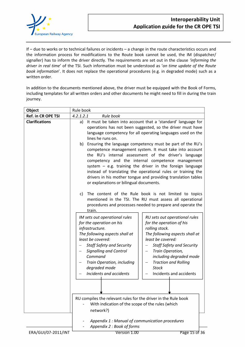
Object Rule book
Ref. in CR OPE TSI 4.2.1.2.1 Rule book
Clarifications a) It must be taken into account that a ‘standard’ language for operations has not been suggested, so the driver must have language competency for all operating languages used on the lines he runs on.
b) Ensuring the language competency must be part of the RU’s competence management system. It must take into account the RU’s internal assessment of the driver’s language competency and the internal competence management system – e.g. training the driver in the foreign language instead of translating the operational rules or training the drivers in his mother tongue and providing translation tables or explanations or bilingual documents.
c) The content of the Rule book is not limited to topics
mentioned in the TSI. The RU must assess all operational procedures and processes needed to prepare and operate the train.
IM sets out operational rules for the operation on his infrastructure. The following aspects shall at least be covered:
Staff Safety and Security
Signalling and Control Command
Train Operation, including degraded mode
Incidents and accidents
RU sets out operational rules for the operation of his rolling stock. The following aspects shall at least be covered:
Staff Safety and Security
Train Operation, including degraded mode
Traction and Rolling Stock
Incidents and accidents
RU compiles the relevant rules for the driver in the Rule book - With indication of the scope of the rules (which
network?)
- Appendix 1 : Manual of communication procedures - Appendix 2 : Book of forms

ERA/GUI/07-2011/INT Version 1.00 Page 16 of 36
Interoperability Unit Application guide for the CR OPE TSI
The requirement that the rules are presented in the same format is mandated so as to ensure that drivers are presented with the different rules for the various networks in a consistent manner using one rule book as the basic part, supplemented by part(s) that cover the rules that are different from those in the basic part per network. It is imperative that the driver is able to find the rules relating to the same situations in the same sections of the different parts of the document irrespective of the infrastructure on which he is running. Therefore a simple compilation of national rulebooks without reorganising them is not sufficient.
Interfaces with other Directives, Recommendations, TSIs, etc.
The Train Drivers Directive [3] 2007/59/EC must be considered when defining the relevant language competencies.
Interfaces with other documents (ENs, UNI, etc.)
None
Object Route book
Ref. in CR OPE TSI 4.2.1.2.2.1 Preparation of the Route book
Clarifications a) On this topic there are some aspects that need to be considered:
information on which means of communications are to be used: track to train radio, signal post phones, etc. a hierarchy of the contact media is required, especially for the case of degraded situations. This is necessary to enable the driver to contact the signaller in the way required/intended by the IM for normal operation as well as degraded mode.
When establishing this information, it must be taken into account that the signaller has the lead responsibility in the conversation. He must ensure that, depending on the driver’s information about train identity (running number) and position, the driver is connected to the competent signaller. This might require referring the call to another signaller.
b) It must be taken into account that a ‘standard’ language for
ERA/GUI/07-2011/INT Version 1.00 Page 17 of 36
Interoperability Unit Application guide for the CR OPE TSI
operations has not been suggested, so the driver must have the competency for all operating languages used on the lines he runs on.
c) Ensuring the language competency must be part of the RU’s competence management system. See also the explanations on the Rule book.
Interfaces with other Directives, Recommendations, TSIs, etc.
The Train Drivers Directive [6] EC must be considered when defining the relevant language competencies.
Interfaces with other documents (ENs, UNI, etc.)
None
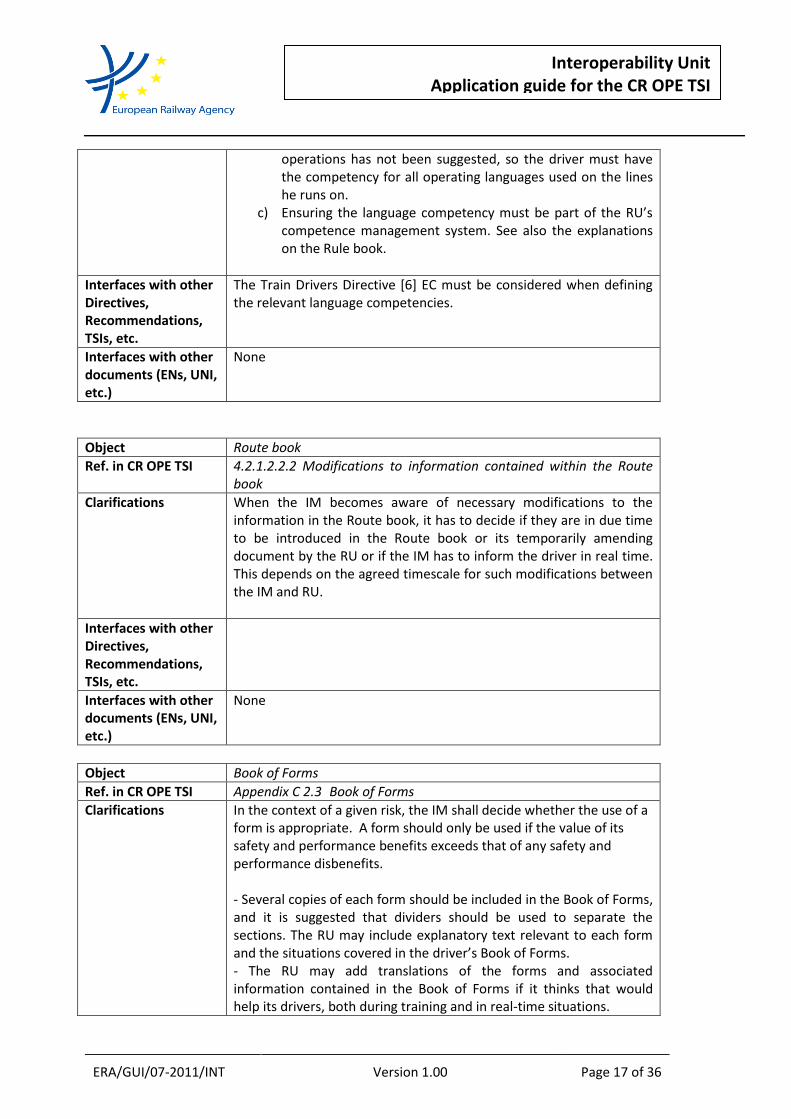
Object Route book
Ref. in CR OPE TSI 4.2.1.2.2.2 Modifications to information contained within the Route book
Clarifications When the IM becomes aware of necessary modifications to the information in the Route book, it has to decide if they are in due time to be introduced in the Route book or its temporarily amending document by the RU or if the IM has to inform the driver in real time. This depends on the agreed timescale for such modifications between the IM and RU.
Interfaces with other Directives, Recommendations, TSIs, etc.
Interfaces with other documents (ENs, UNI, etc.)
None
Object Book of Forms
Ref. in CR OPE TSI Appendix C 2.3 Book of Forms
Clarifications In the context of a given risk, the IM shall decide whether the use of a form is appropriate. A form should only be used if the value of its safety and performance benefits exceeds that of any safety and performance disbenefits. - Several copies of each form should be included in the Book of Forms, and it is suggested that dividers should be used to separate the sections. The RU may include explanatory text relevant to each form and the situations covered in the driver’s Book of Forms. - The RU may add translations of the forms and associated information contained in the Book of Forms if it thinks that would help its drivers, both during training and in real-time situations.

ERA/GUI/07-2011/INT Version 1.00 Page 18 of 36
Interoperability Unit Application guide for the CR OPE TSI
This depends on the RU’s internal driver competence management system. The RU might decide to train the driver in the foreign language instead of translating the operational rules or to train the driver in his mother tongue and provide translation tables or explanations or bilingual documents.
Interfaces with other Directives, Recommendations, TSIs, etc.
Interfaces with other documents (ENs, UNI, etc.)
None
5.3 Train characteristics
Object Train visibility – front-end indication
Ref. in CR OPE TSI 4.2.2.1 Train visibility
Clarifications Each train has to be equipped with a front-end indication formed by three white lights. It is relevant that the three white lights form an isosceles triangle. The upper light may be above or below the windscreen. This requirement is a technical as well as a procedural requirement. As a technical requirement, it is met by a functional requirement for Rolling Stock in the respective RST TSIs. The RST TSIs apply only to new, upgraded or renewed Rolling Stock. Vehicles running on the front end of a train which do not comply with the RST TSIs might not have the three white lights on the front end. From an operational point of view, a gradual transition from the existing train front-end signal (if different from that defined in the CR OPE TSI) to the new signal is possible and expected.
Interfaces with other Directives, Recommendations, TSIs, etc.
See section 4.3 of CR OPE TSI – clause 4.3.2 Interfaces with CCS TSI and clause 4.3.3 Interfaces with RST TSI.
Interfaces with other documents (ENs, UNI, etc.)
Object Train visibility – rear-end indication
Ref. in CR OPE TSI 4.2.2.2 Train visibility
Clarifications a) Passenger coaches and train sets must be equipped with (at least) two red lights on a horizontal axis. This operational

ERA/GUI/07-2011/INT Version 1.00 Page 19 of 36
Interoperability Unit Application guide for the CR OPE TSI
requirement is applicable for both existing and new Rolling Stock.
For new, upgraded or renewed Rolling Stock, the detailed requirements on luminosity etc. are stipulated in the RST TSIs.
b) The requirement for train rear-end indication for freight trains has not yet been harmonised in Europe. In Finland, no train rear-end indication is considered necessary. In some countries, lamps are required; in others (reflective) plates are used. The CR OPE TSI therefore stipulates a train rear-end signal of either lamps or plates for freight trains crossing borders between MS. The MS has to indicate whether lamps or plates are required.
Normally, a train should be equipped with two identical indicators. If one of the indicators fails, it shall be replaced according to the RU internal rules for degraded mode for such a case. The operating rules must take into account which indicators are allowed on the network(s) the train will run on.
c) As the train rear-end signal is an open point for freight trains
not crossing borders, the national technical rules notified in accordance with Article 17(3) of the Interoperability Directive shall apply. This means that the MS has to notify which type (including size, shape, colour and position, if necessary) of indication is required.
Interfaces with other Directives, Recommendations, TSIs, etc.
TSI WAG revised, draft
Interfaces with other documents (ENs, UNI, etc.)
Object Train audibility
Ref. in CR OPE TSI 4.2.2.2 Train audibility The ability to sound the audible warning device must be possible from all driving positions.
Clarifications The driving position depends on the design of the driving cab as agreed between keeper and manufacturer.
Interfaces with other Directives, Recommendations, TSIs, etc.
See section 4.3 of CR OPE TSI – clause 4.3.2 Interfaces with CCS TSI and clause 4.3.3 Interfaces with RST TSI.

ERA/GUI/07-2011/INT Version 1.00 Page 20 of 36
Interoperability Unit Application guide for the CR OPE TSI
Interfaces with other documents (ENs, UNI, etc.)
5.4 Train composition and preparation The requirements on train composition are set out in clause 4.2.2.5 of the CR OPE TSI. These requirements take into account those of clause 4.2.2.7 whereas the RU has to ensure that the train is fully functional before and throughout the train run. This requirement cannot be overstated. The RU must ensure that all vehicles as well as the combination of vehicles in a train or a train set fulfil all requirements regarding safety and the route that the train shall be operated on. This includes not only the vehicles themselves, but also the freight load and securing the load on or in the vehicle. Some of the measures are carried out by the RU itself, and for some the RU subcontracts other players such as keepers, Entities in Charge of Maintenance or even the IM (e.g. maintenance of vehicles, train departure procedures). But even by subcontracting some of the tasks to other players, the RU has the overall responsibility. Therefore requirements relating to the RU’s responsibility (even if they have been or are still fulfilled by the IM in some countries) are deleted or described in less detail in the CR OPE TSI in comparison to the former CR OPE TSI (2006/920/EC). This does not mean that the requirements do not exist anymore. Instead, the RU must decide how to fulfil its obligations and, if necessary, agree with the IM on rules for procedures that the IM takes over from the RU.
Object Train composition
Ref. in CR OPE TSI 4.2.2.7.1 General requirement
Clarifications On this topic there are some aspects that need to be considered: a) The train composition must be planned in advance in order to
request a path suitable for the train. Therefore the RU has to indicate general characteristics that influence the choice of routes as well as other constraints (e.g. gauge, vehicle’s speed limits, etc.).
b) The actual train composition must always be such that the train may run on the routes planned. This includes aspects such as train length, gauge, axle load, accepted braking systems, braking performance, CCS equipment on board, etc. If the characteristics differ from those indicated to the IM, the RU has to inform the IM about this. If necessary, a new path may be allocated or the allocated path amended. (Commercial aspects are not the subject of the TSI and therefore not mentioned here.).
c) For each train, the RU has to ensure that they know the train composition during the whole train run. This is necessary to cope with all possible risks during the train run. For example, in case of an accident, the IM must be informed about specific details of the

ERA/GUI/07-2011/INT Version 1.00 Page 21 of 36
Interoperability Unit Application guide for the CR OPE TSI
train (dangerous goods on the train? Which EVN? Which position in the formation?).
Interfaces with other Directives, Recommendations, TSIs, etc.
Train Path Allocation Directive 2001/14/EC Directive 2008/68/EC of 24 September 2008 on the inland transport of dangerous goods
Interfaces with other documents (ENs, UNI, etc.)
UIC leaflet 421
Object Braking performance
Ref. in CR OPE TSI 4.2.6 Braking performance
Clarifications Due to the complexity of this topic, it is described in greater detail in chapter 6
5.5 Safety of load and passengers
Object 4.2.2.4. Safety of passengers and load
Ref. in CR OPE TSI 4.2.2.4.1 Safety of load
Clarifications The RU must ensure that vehicles are safely and securely loaded, and remain so throughout the journey. The RU shall consider for example the following aspects: Weight distribution Vehicles must be loaded so as to evenly distribute the weight of the load over all the axles. Where, due to the size or shape of a particular load, this is not possible, the RU must apply special conditions of travel to the load for the entire journey. Axle loading The RU must ensure that vehicles are not loaded beyond their axle load limit. It must also ensure that vehicles are not loaded beyond the axle load limit of any part of the planned route (unless the IM(s) concerned have authorised the movement). Load securing The RU must ensure that loads and any unused load securing equipment on or in vehicles are secured in a safe manner to prevent unnecessary movement during the journey.
Kinematic envelope The kinematic gauge of each vehicle (inclusive of any load) in the train must be within the maximum permissible for the section of route.
Load covering The RU must ensure that any materials used to provide a cover for a load

ERA/GUI/07-2011/INT Version 1.00 Page 22 of 36
Interoperability Unit Application guide for the CR OPE TSI
on a vehicle are safely attached either to the vehicle or to the load. These coverings must be made of materials that are suitable to cover the load in question, taking into account the forces that are liable to be experienced during the journey.
Interfaces with other Directives, Recommendations, TSIs, etc.
INF TSI
Interfaces with other documents (ENs, UNI, etc.)
Examples: UIC leaflet 700 GCU Art. 29
5.6 Train identification
Object Train identification
Ref. in CR OPE TSI 4.2.3.2 Identification of trains
Clarifications The CR OPE TSI requires that each train must be identified uniquely. The standard means for this is the train running number. Due to existing CCS systems and other IT systems, the total number of train running numbers is limited; the numbers must be reused on the European network. To ensure that trains can be correctly identified, it must be ensured that each train running number is unique per network. In this case, it means not only the rail network, but also the IT networks of GSM-R and ETCS, for example. If the IT systems have a different geographical extent to the rail network, the different extents must be compared. The largest extent must be considered when assigning the train numbers. If – for example – two IMs decide to establish one common GSM-R network, these IMs would have to ensure that a train running number is not repeated on the network of the other IM because they operate on the same GSM-R network. The train running number is allocated by the IM allocating the train path. In doing so, he should cooperate with other IMs to ensure that the number is not reused unnecessarily. Furthermore, the IM has to ensure that all parties concerned (the RU and other IMs) are informed about the allocated train number and possible changes. Changes of the train running number should be avoided as much as possible. If a change is necessary, the IM has to inform the RU and other IMs about the change. If absolutely necessary, the change of a train running number should be

ERA/GUI/07-2011/INT Version 1.00 Page 23 of 36
Interoperability Unit Application guide for the CR OPE TSI
made when the train is at standstill (because the driver has to make data entries, and clear addressing by the signaller and others must be possible during the train run).
Interfaces with other Directives, Recommendations, TSIs, etc.
Interfaces with other documents (ENs, UNI, etc.)
One of the possible supports is UIC leaflet 419
5.7 Train run
Object Sanding
Ref. in CR OPE TSI Appendix B (C1) Use of sanding
Clarifications The application of sand is an effective way of improving the adhesion of wheels to the rail, to aid braking and starting off, especially in conditions of low/poor rail adhesion. A build-up of sand on the railhead may cause a number of problems, especially in connection with the activation of track circuits and the effective operation of points and crossings. This should be taken into account in the IM’s operational rules and the driver’s rule book.
Interfaces with other Directives, Recommendations, TSIs, etc.
Interfaces with other documents (ENs, UNI, etc.)

ERA/GUI/07-2011/INT Version 1.00 Page 24 of 36
Interoperability Unit Application guide for the CR OPE TSI
6 BRAKING PERFORMANCE
6.1 Principles Braking performance is a subject that concerns both the IM and RU. Appendix T of the CR OPE TSI clarifies the interface between the IM and RU:
allocation of responsibilities,
communication relating to braking performance. In any case, the IM and RU have to work together and exchange information to ensure the safe operation of trains. The IM and RU must ensure that the risks occurring at the interface between the IM and RU are analysed and covered by operational rules and procedures in accordance with Article 9(2) of the Safety Directive [2].
In many EU countries many different IMs operate, and it is regarded as beneficial if the rules of different IMs within one Member State are harmonised (being their eventual harmonisation throughout Europe the goal in the long term).
6.2 Responsibilities of the IM and RU The IM must ensure that the correct and complete requirements concerning braking performance are given to the RU. He has to indicate to the RU the conditions of use of brake systems affecting the infrastructure (route-related information). He also provide route characteristics that the RU must take into account for the tuning of braking performance. This shall cover for example steep gradients that lead to overheating of the brake blocks or information on how to secure a train, and other specific information. The IM shall also provide the rules for constraints that the RU has to respect if a train does not reach the required braking performance (either general rules or line-related, as appropriate).
The RU establishes rules for the train composition and the calculation of the braking performance reached by a train (general rules) to ensure that the trains run safely. This shall include normal and degraded mode operation. The rules must take into account constraints such as the availability and reliability of the brakes. The rules must also take into account train running characteristics such as longitudinal forces (and associated risks of coupler breakage). These general rules established by a RU may be the same for all networks the RU is running on as the train’s characteristics and behaviour do not change by crossing a border (exception: considerable changes in climatic conditions, for example) – however the required braking performance may vary from route to route.
The standard unit for expressing braking performance is brake weight percentage. Nevertheless the IM and RU may agree or have agreed on other units such as deceleration values or deceleration profiles or braked tonnes. EN 14531 and UIC 544-1 define such parameters as brake weight percentage.

ERA/GUI/07-2011/INT Version 1.00 Page 25 of 36
Interoperability Unit Application guide for the CR OPE TSI
6.3 Procedures
6.3.1 Preparation
The IM establishes general braking performance requirements for all routes. The requirements may include a distinction between different types of train. He makes the requirements for braking performance available to the RUs. The IM also indicates related information such as the conditions of use for brake systems that may have an impact on the infrastructure, such as eddy-current and a magnetic or regenerative brake.
The RU establishes rules for train composition and braking performance calculation. The braking performance resulting from the checking of the actual train (train composition, brake availability, train length, brake settings, etc.) will be used as an input value for any operation rule to be subsequently applied to the train. This means that the result of the calculation shall be used as such (e.g. brake weight percentage (%) to be used as calculated; ranges in a table may be derived as written without further deduction).
The decision on which brake setting to use (e.g. P or G or combination of brake systems) for a train is then up to the RU, taking into account the relevant train characteristics such as length, type of couplers, etc. However, the prescribed braking performance must at least be achieved.
6.3.2 Train prepared to run The RU calculates the actual braking performance for the train prepared to run and verifies that this braking performance matches or exceeds the IM’s requirement. The RU must not take into account any brake system that is not allowed on the given route.
6.3.3 Braking performance insufficient If the achieved braking performance does not meet the requirement, the train may have to run at a lower speed than indicated for the relevant route, according to the rules provided by the IM. The operational management of the train is then decided between the IM and RU: if the speed limitation would cause severe traffic disturbance, the train could be sided in order to wait for a traffic low, or even rescue or lineside repair, etc. For such situations, the IM shall prepare rules that are provided to the RU in advance. They shall indicate which restrictions have to be respected according to the achieved braking performance. These rules are supposed to give the RU an adapted, safe speed limit and/or other constraints without starting long discussions with the IM before the train can run (again). The design of these rules is left open to the IM: the IM may decide to create different categories, or different variations of the required braking performance.
Examples:
Train achieves 60 brake weight % : originally permitted speed minus 15 km/h
Train achieves 40 brake weight %: originally permitted speed minus 25 km/h
Train achieves required brake weight % minus 10%: 60 km/h permitted
Train achieves required brake weight % minus 20%: 50 km/h permitted

ERA/GUI/07-2011/INT Version 1.00 Page 26 of 36
Interoperability Unit Application guide for the CR OPE TSI
For each brake weight % missing, the maximum speed allowed shall be reduced by 5 km/h.
Braking curves / braking profiles may be adapted. The rules may be designed as one set of rules valid for the whole network or as route-specific rules. In some cases, train operation will not be possible (according to the rules for reduced braking performance), either because of safety reasons (e.g. impossibility to halt a train on steep gradients) or for traffic management reasons (traffic disruption due to the resulting speed limit). In these cases, one possibility is to make a request for an ad hoc path in accordance with the braking performance achieved.
6.4 Establishing operational rules
6.4.1 Safety Management System It is vital to ensure that consistent operational procedures are applied in all cases. This means that all rules and procedures must be managed by the IM’s ad RU’s Safety Management System. If necessary, a risk assessment as indicated by the Common Safety Methods [reference to the CSM recommendation] shall be carried out.
6.4.2 Application of existing rules Experience shows that railways have operated in a safe manner for a long time with the existing braking performance rules. The RU may, if it so decides, take over existing rules from another body (e.g. in different countries the IMs previously managed these rules). These rules may also be used in other countries, as the train’s behaviour does not change during a run – unless the train composition is changed. (The different route characteristics are mirrored in the IM’s requirements.) These rules may be regarded as a ‘Code of practice’ in the sense of the Common Safety Methods. If the RU applies the same rules as before, an additional assessment appears not to be necessary.
6.4.3 Establish new / amend existing rules If the RU decides to establish new rules or amend the existing ones, a risk assessment according to the CSMs [11] has to be carried out. The technical parameters listed in EN 14198:2004 and EN 14531, as well as UIC leaflet 544-1 should be taken into account for the risk assessment. Technical development shall not be hindered. If technical devices improve braking performance at train level, the RU shall be allowed to take this improvement into account. Such a decision shall also be covered by a risk assessment.
6.5 Standardised calculation: brake weight percentage The calculation for the infrastructure-related braking performance requirement cannot be harmonised due to different infrastructure characteristics in different countries (e.g. length of block sections). For train-braking performance, the most common formula for conventional rail is the following:

ERA/GUI/07-2011/INT Version 1.00 Page 27 of 36
Interoperability Unit Application guide for the CR OPE TSI
Sum of brake weight, including locos x100 = Brake weight percentage Sum of total weight of the train, including locos Note: The sum of brake weight is performed over the brake weight of active brakes only. The brake weight of each vehicle is determined when the vehicle is placed in service. The sum of total weight is the actual or estimated (higher) weight (mostly written on the vehicle).
6.6 Correction coefficient For long-haul trains, the pneumatic (UIC) brake build-up time can be significantly degraded. This must be considered when calculating the actual braking performance as a brake weight percentage. For other braking performance calculations such as deceleration profiles, it can already be included in the determined values. The RU has to ensure that a suitable correction coefficient is used for such trains. The change in behaviour (first of all brake build-up time) is reflected in the correction coefficient ‘kappa’. ‘Kappa’ has been introduced by UIC leaflet 544-1. It is recommended that UIC 544-1 be applied to ensure transparency between the IM and RU and to help the new RUs to determine a realistic braking performance for all trains.
6.7 CR OPE TSI and CCS TSI (ETCS) – a contradiction? First, it must be understood that the requirements of this appendix and the braking values for the European Train Control System (ETCS) are used in different steps of the whole procedure for running a train. Appendix T sets out the rules on how to exchange data between the IM and RU before running a train, thus in the preparation phase. The braking performance value is the means by which the IM indicates the minimum requirement for the braking performance of the train that will run on the path requested by the RU. The RU may decide to calculate the actual braking performance of the train (almost) ready for departure in the same unit as the value required by the IM. The RU also has the possibility – if safety of this conversion is ensured – to translate the IM’s requirement into the braking performance unit used internally. This might be a deceleration value or other unit. The ETCS on the other hand affects the braking and braking performance of a train while the train is running. Based on the value for the achievable braking performance of the train, the deceleration profile is calculated on board and applied accordingly. Here, an exchange of values takes place between the CCS components on the track and the CCS components on board. Therefore, a common unit for the ETCS is important. The relevant value is the deceleration value. Acknowledging the necessity of the deceleration value for the ETCS, the system allows the use of deceleration values as well as brake weight percentages as input data thanks to its conversion model for the input of brake weight percentage on board. Why not use the deceleration value then also in Appendix T?

ERA/GUI/07-2011/INT Version 1.00 Page 28 of 36
Interoperability Unit Application guide for the CR OPE TSI
The CR OPE TSI requires the brake weight percentage as the default unit because for most existing vehicles operated in Europe on conventional lines – especially freight wagons – only the brake weight percentage can be determined with the information available.
ERA/GUI/07-2011/INT Version 1.00 Page 29 of 36
Interoperability Unit Application guide for the CR OPE TSI
7 EUROPEAN VEHICLE NUMBER: APPENDIX P Before entering into the details of Appendix P, it must be understood that two versions of Appendix P exist: Appendix P is valid until 31.12.2013; Appendix P (a) will then enter into force on 01.01.2014. The following explanations refer to Appendix P.
7.1 Players in the issuing of a European Vehicle Number
7.1.1 Applicant The applicant seeking to put a new vehicle into service for the first time sends the technical file to the NSA of the Member State in accordance with Article 22 of the Interoperability Directive [1]. A request for putting a vehicle into service after a renewal or upgrade is also regarded as putting a vehicle into service for the first time.
7.1.2 National Safety Authority The National Safety Authority authorises the placing in service of the vehicle.
7.1.3 Registration entity (entity in charge of the NVR) The registration entity of the MS whose authority authorised the placing in service of the vehicle issues the European Vehicle Number according to the vehicle’s technical characteristics described in the technical file, and registers the vehicle in the National Vehicle Register (NVR). The details of the different codes are listed in Appendix P of the TSI; additional explanations are given in chapter 2 of this guide. The registration entity may be – but is not necessarily – the NSA.
7.1.4 European Railway Agency (ERA) The European Railway Agency (ERA) publishes part 9 Appendix P on its public website. If new codes are to be created in part 9, the registration entity concerned requests a new code from the central body; the French NSA, EPSF, is currently acting as central body on behalf of the registration entities.
7.2 Basic principles for the European Vehicle Number (EVN)
7.2.1 Scope / Vehicles concerned A European Vehicle Number (EVN) is required for all vehicles (Article 32 of the Interoperability Directive [1]). As the Interoperability Directive limits the scope and lists exemptions, the requirement in the CR OPE TSI must be understood within the limits set by the Interoperability Directive. The only exemption permitted concerns vehicles that are to be operated from or to third countries with a track gauge other than 1435 mm (e.g. 1520/1524 mm). If a vehicle is clearly and uniquely identified with a number from another coding system, the Member States may accept this different number (Article 32(5) of the Interoperability Directive [1]).

ERA/GUI/07-2011/INT Version 1.00 Page 30 of 36
Interoperability Unit Application guide for the CR OPE TSI
The Operation and Traffic Management TSI, clause 4.2.2.3 [3], [4] requires that each vehicle must have a number to uniquely identify it from any other rail vehicle.
7.2.2 How to obtain a European Vehicle Number? The principle of the European Vehicle Number is laid down in Article 32 of the Interoperability Directive [1]. First, it must be understood that the European Vehicle Number (old name: 12-digit-number) is given by the registration body of the Member State in which the first authorisation is issued. The number shall stay with the vehicle for its lifetime. Only if the vehicle is modified and the number does not reflect the technical characteristics it shall be changed. Further details are given in Decision 2007/756/EC on the National Vehicle Register [12]. This means that when applying for an authorisation for the placing in service of a vehicle in accordance with Articles 22 or 24 of the Interoperability Directive [1], technical details about this vehicle have to be transmitted to the National Safety Authority. When the vehicle has been authorised to be placed in service for the first time, the registration entity of this Member State will register the vehicle in its National Vehicle Register and give a European Vehicle Number to each vehicle, based on the vehicle’s technical characteristics and the related codes specified in Appendix P of the HS and CR OPE TSIs [3], [4]. For the structure of this European Vehicle Number and the codes of the parts of the number, specifications are laid down in Appendix P of the HS and CR OPE TSIs [3], [4] both amended by Decision 2010/640/EC). These specifications are binding for all registration entities in the Member States of the European Union. Some explanations or additional information is set out below for Appendix P of the HS and CR OPE TSIs [3], [4].
7.3 The parts of Appendix P
7.3.1 Part 1: Keeper’s abbreviation marking (VKM) This part lays down the principles for the Vehicle Keeper Marking (VKM). Rules on the application and assignment of a VKM can be found in the ‘Rules for the registration of a vehicle keeper marking (VKM)’, published on the ERA website: www.era.europa.eu. The list of VKMs is also available on the ERA website. Please note that the keeper is registered in the NVR and marked as VKM on the vehicle. The physical marking may not be up to date due to a transition period set out in the recast CR OPE TSI. In case of contradiction, the registration in the NVR supersedes the physical marking.
7.3.2 Part 2: Inscription of the number and linked alphabetical marking on the bodywork This part states the basic requirements concerning the marking on vehicles. It must be seen in connection with the requirements of the relevant TSIs for Rolling Stock concerning markings on vehicles. It must be understood that the marking of wagons and coaches do not follow the same rules due to historical reasons, so different schemes may occur.

ERA/GUI/07-2011/INT Version 1.00 Page 31 of 36
Interoperability Unit Application guide for the CR OPE TSI
The standardised letter codes for wagons and hauled passenger coaches are listed in parts 12 and 13. For special vehicles, the letter codes are listed in EN 14033-1:2009. For further details about the marking of railway vehicles, also see prEN 15877.
7.3.3 Part 3: Rules for the determination of the check digit (digit 12) The calculation of the check digit is explained in detail in part 3, so no further explanations are given here.
7.3.4 Part 4: Coding of the country in which the vehicle has been registered (digits 3-4 and abbreviation)
This part lists the different codes for the registration entities of the different Member States. It must be understood that the code indicates a registering country, not the territory in which the vehicle will run. For further information, also see NVR Decision 2007/756/EC [4]. As the meaning of digits 3 and 4 has been changed by the CR OPE TSI [2], the following ‘historic’ information must be given: In the past, ‘institutional’ railway companies took care of the placing in service of vehicles, and the code composed of the digits 3 and 4 represented a particular national railway company, not a country. As vehicles that have been placed in service before the entry into force of the Interoperability Directives and the Safety Directive are allowed to run without NSA authorisation as long as they are not renewed or upgraded, the old codes must still be known. The registration of these vehicles is specified in the NVR Decision [4]. Vehicles for which the following table applies may be identified by the marking ‘RIV’ or ‘RIC’.

ERA/GUI/07-2011/INT Version 1.00 Page 32 of 36
Interoperability Unit Application guide for the CR OPE TSI
The former meaning of the codes was:
Country Code of registering
country as listed in part 4
Historical railway companies with the allocated codes
before entry into force of the CR OPE TSI (2006/920/EC)
Country Code of registering
country as listed in part 4
Historical railway companies with the allocated codes
before entry into force of the CR OPE TSI (2006/920/EC)
Austria 81 ÖBB Latvia 25 LDZ
Belgium 88 SNCB/NMBS Lithuania 24 LG
Bulgaria 52 BDZ, SRIC Luxembourg 82 CFL
Czech Republic 54 ČD Netherlands 84 NS
Denmark 86 DSB, BS Norway 76 NSB, JBV
Estonia 26 EVR Poland 51 PKP
Finland 10 VR, RHK Portugal 94 CP, REFER
France 87 SNCF, RFF Romania 53 CFR
Germany 80 DB Slovak Republic 56 ŽSSK, ŽSR
68 AAE Slovenia 79 SŽ
Greece 73 CH Spain 71 RENFE
Hungary 55 MÁV Sweden 74 GC, BV, SJ
43 GySEV/ROeEE Switzerland 85 SBB/CFF/FFS
Ireland 60 CIE 63 BLS
Italy 83 FS United Kingdom 70 BR
64 FNME
7.3.5 Part 5: Alphabetical marking of the interoperability capability Vehicles which:
comply with all relevant TSIs in force at the time of placing in service and which have been authorised to be placed in service in accordance with Article 22(1) of Directive 2008/57/EC, and
are provided with an authorisation valid in all Member States in accordance with Article 23(1) of Directive 2008/57/EC,
shall be marked with ‘TEN’.
This means that the relevant TSIs for Rolling Stock (including for example the TSIs for Noise (NOI) and People with Reduced Mobility (PRM)) have been met, and the vehicle has been cross-authorised.

ERA/GUI/07-2011/INT Version 1.00 Page 33 of 36
Interoperability Unit Application guide for the CR OPE TSI
Vehicles that are placed in service in accordance with the other procedures stipulated in Articles 21-25 of the Interoperability Directive [1] may not carry the marking ‘TEN’. They shall carry a derogation plate with the letter marking of the Member States in which the vehicles have been placed in service. The Member States’ abbreviations shall be used according to part 4. The marking ‘PPV’ or ‘PPW’ is not given by Member States of the European Union.
7.3.6 Part 6: Interoperability codes used for wagons (digits 1-2) This part defines the first two digits of an EVN for wagons. To ensure consistent codes with RUs operating outside the European Union, it is necessary to agree on these with the Intergovernmental organisation for international carriage by rail (OTIF) and PPV/PPW1; therefore the COTIF2 and PPV/PPW codes are also listed in the tables. For EU Member States, only the decision on ‘TSI-compliant vehicle’ or not (other wagons) is necessary. Further details can be found in the table.
7.3.7 Part 7: International Traffic ability codes used for hauled passenger vehicles (digits 1-2)
This part defines the first two digits of an EVN for coaches. To ensure consistent codes with RUs operating outside the European Union, it is necessary to agree on these with the OTIF and PPV/PPW; therefore the COTIF and PPV/PPW codes are also listed in the tables. For EU Member States, the PPV tables are not relevant. Further details can be found in the table. All fields marked as ‘not to be used’ are kept for further developments; the revision of these tables is to be done during a revision of Appendix P of CR OPE TSI by the European Commission.
7.3.8 Part 8: Types of tractive stock (digits 1-2) Most of the EU Member States use the table listed in part 8.
The distinction between codes 1 and 2 or 7 and 8 depends on the national definition for shunting engines.
The distinction between High-Speed and others (codes 3 and 4) shall be taken according to the distinction in the TSIs for Rolling Stock.
Codes 3, 4 and 5 include driving trailers and intermediate trailers.
The codes for Diesel (2, 5 and 8) shall also be used for biofuel and other trackside-independent energy supplies.
Code 6 is for specialised trailers, depending on national definition. Example: trailers put into a train to ensure the heating for passenger coaches because the locomotive is not compatible with the coaches’ heating system.
7.3.9 Part 9: Standard numerical marking of wagons (digits 5 to 8) This part is a Technical Document maintained by ERA and published on the ERA website. The registration entity decides which code is to be used for a wagon to be registered. The 4-digit code is based on a letter code which is given to each wagon in accordance with part 12.
1 Wagon which complies with PPV/PPW agreement (inside OSJD States) (original: ППВ (Правила пользования
вагонами в международном сообщении). 2 Convention concerning International Carriage by Rail.

ERA/GUI/07-2011/INT Version 1.00 Page 34 of 36
Interoperability Unit Application guide for the CR OPE TSI
If a new code is required, the registration entity will request it from ERA. The procedure for this request is described in ‘Rules for maintenance of technical descriptions in the European Vehicle Number’ (part 9 of CR OPE TSI). How to determine the code Code of Technical Characteristics (digits 5-8) Each EVN of a wagon includes coded information about technical characteristics. Letter marking The competent authority defines the letter marking of the wagon based on its technical file according to part 12 of CR OPE TSI. From these technical characteristics, the correct letter marking can be derived: Example: Falls Falls means: F = Open High-Sided Wagon a = with 4 axles ll = with bulk gravity unloading, on both sides, simultaneously, at the bottom (a)
(a) Wagons with gravity unloading in category F are open wagons, which do not have a flat floor and
have no tipping facility, either at the end or the side. s = wagons authorised to run in condition ‘s’ (see Annex B of the Conventional Rolling Stock – Freight Wagons TSI)
Code for the technical characteristics for the wagon This letter code has to be translated into a number code (digits 5-8) as stated in part 9. According to the letter marking, the correct digits 5-8 have to be looked up in part 9: F means the first of the 4 technical digits (5-8) is: xx xx 6xxx xxx-x
Extract from Appendix P, part 9, Table 6-F

ERA/GUI/07-2011/INT Version 1.00 Page 35 of 36
Interoperability Unit Application guide for the CR OPE TSI
For further details, another table in part 9 has to be
considered:
Extract from part 9
If the number code is already listed in part 9, the competent authority uses this code for the new
wagon to be authorised for placing in service.
Example: the sixth digit is a 6 (derived from the column): xx xx 66xx xxx – x.
According to the table for the vehicles with a 6 as fifth digit, 10 possible combinations have been
reserved: 6675 - 6683.
Serial number and its influence on the code for the technical characteristics The decision as to which number to take depends on the number of wagons already registered with
these technical characteristics. If less than 1 000 vehicles of one type are registered in a country, a
coherent serial number may be taken:
Example (a): So the wagon could be: xx xx 6675 xxx – x.
In combination with the serial number, the wagon would be registered with the number
xx xx 6675 xxx – x.
New code needed If a code for a combination of letters of part 12 does not yet exist or all 1 000 serial numbers of one
code are already in use, a new number code must be created according to the rules explained in
part 9. This new code must be introduced in part 9 and may then be given to other wagons with
identical technical characteristics as stated in part 12.

ERA/GUI/07-2011/INT Version 1.00 Page 36 of 36
Interoperability Unit Application guide for the CR OPE TSI
Example (b): Here it was necessary to introduce a new combination; the new vehicle would therefore
be registered with the number xx xx 6684 001 – x.
7.3.10 Part 10: Codes for the technical characteristics of the hauled passenger stock (digits 5-8)
This part is a Technical Document maintained by ERA and published on the ERA website.
7.3.11 Part 11: Codes for the technical characteristics of the special vehicles (digits 6-8) This part is mainly related to maintenance vehicles. As listed in the table, one digit (digit 6) is defined by the vehicle’s speed limit and its ability to be put into a train. The digits 7 and 8 derive from the vehicle’s purpose. For the 7th digit with the code 0 (Rail/road): the different categories of rail/road machines are defined in EN 15746-1:2008. It is recommended that this standard be applied to ensure a common code for rail/road machines throughout Europe.
7.3.12 Parts 12-14: Letter markings These parts translate various technical characteristics of different types of Rolling Stock into letter codes that are to be marked physically on the vehicles. Once the letter code has been determined according to the relevant part of Appendix P, the numerical code can be determined (see example in part 9).


![Guide for the application of the TSI OPE - Saferail · [4] Directive 2012/34/EU of the European Parliament and of the Council of 21 November 2012 establishing a single European railway](https://static.fdocuments.in/doc/165x107/5fd2c964da3fa2318655acf8/guide-for-the-application-of-the-tsi-ope-saferail-4-directive-201234eu-of.jpg)