
Guide for Gas Transmission, Distribution and Gathering ... · Enclosed is Addendum to ANSI GPTC...
116
American Gas Association 400 N. Capitol St., NW Washington, DC 20001 Michael Bellman GPTC Secretary (202) 824-7183 [email protected] January 9, 2017 Dear Guide Purchaser, Enclosed is Addendum 6 to ANSI GPTC Z380.1, Guide for Gas Transmission, Distribution and Gathering Piping Systems, 2015 Edition. Addenda are formatted to enable the replacement of pages in your Guide with the updated enclosed pages. Please follow the enclosed page replacement instructions. On behalf of the Gas Piping Technology Committee and the American Gas Association, thank you for your purchase and interest in the Guide. Sincerely, Secretary GPTC Z380
Transcript of Guide for Gas Transmission, Distribution and Gathering ... · Enclosed is Addendum to ANSI GPTC...

American Gas Association 400 N. Capitol St., NW Washington, DC 20001
Michael Bellman GPTC Secretary (202) 824-7183
January 9, 2017 Dear Guide Purchaser, Enclosed is Addendum 6 to ANSI GPTC Z380.1, Guide for Gas Transmission, Distribution and Gathering Piping Systems, 2015 Edition. Addenda are formatted to enable the replacement of pages in your Guide with the updated enclosed pages. Please follow the enclosed page replacement instructions. On behalf of the Gas Piping Technology Committee and the American Gas Association, thank you for your purchase and interest in the Guide. Sincerely,
Secretary GPTC Z380

B L A N K

1
GPTC GUIDE FOR GAS TRANSMISSION, DISTRIBUTION, AND GATHERING PIPING SYSTEMS
2015 EDITION
ADDENDUM 6, DECEMBER 2016
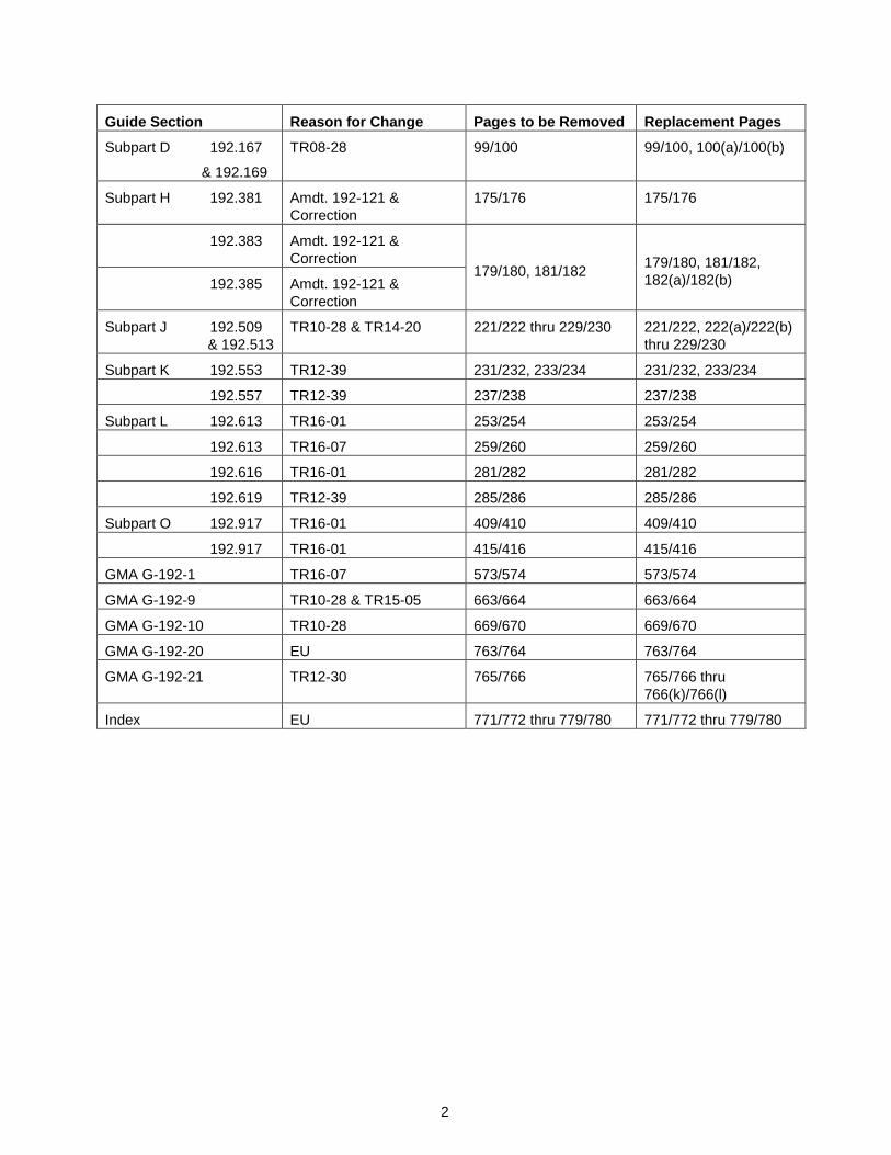
The changes in this addendum are marked by wide vertical lines inserted to the left of modified text, overwriting the left border of most tables, or a block symbol ( ▌) where needed. The Federal Regulations were updated with one amendment and associated correction (amendment 192-121) that affected 3 sections of the Regulations and 4 sections of the Guide. Eight GPTC transactions affected 18 sections of the Guide. Editorial updates include application of the Editorial Guidelines, adjustments to page numbering, and adjustment of text on pages. While only significant editorial updates are marked, all affected pages carry the current addendum footnote. Editorial updates as indicated “EU” affected 6 sections of the Guide (plus other sections impacted by page adjustments, etc.). The table shows the affected sections, the pages to be removed, and their replacement pages.
Key to Reasons for Change Amdt.19X-XXX or docket number: federal regulation amendment TRYY-XX: GPTC transaction with new or updated guide material EU: editorial update
Guide Section Reason for Change Pages to be Removed Replacement Pages
Title Page EU i/ii i/ii
Table of Contents EU v/xii v/xii
GPTC Membership listed by Committee
EU xvii/xviii thru xxxi/xxxii xvii/xviii thru xxxi/xxxii
GPTC Membership listed by member participation
EU
Notice and Disclaimer
Included as Publication Requirement, no action required Editorial Conventions
Editorial Notes
Historical Reconstruction of Part 192
EU xlvii/xlviii xlvii/xlviii
Historical Record of Ammendments to Part 192
EU lxxiii/lxxiv lxxiii/lxxiv
Part 191
Part 191 191.1 TR12-30 1 thru 4 1 thru 4
Part 192
Subpart A 192.1 TR12-30 and Amdt. 192-121
17 thru 20 17 thru 20
192.3 TR08-28 21/22 21/22
Subpart B 192.65 TR15-05 53/54 53/54
2
Guide Section Reason for Change Pages to be Removed Replacement Pages
Subpart D 192.167
& 192.169
TR08-28 99/100 99/100, 100(a)/100(b)
Subpart H 192.381 Amdt. 192-121 & Correction
175/176 175/176
192.383 Amdt. 192-121 & Correction
179/180, 181/182 179/180, 181/182, 182(a)/182(b) 192.385 Amdt. 192-121 &
Correction
Subpart J 192.509 & 192.513
TR10-28 & TR14-20 221/222 thru 229/230 221/222, 222(a)/222(b) thru 229/230
Subpart K 192.553 TR12-39 231/232, 233/234 231/232, 233/234
192.557 TR12-39 237/238 237/238
Subpart L 192.613 TR16-01 253/254 253/254
192.613 TR16-07 259/260 259/260
192.616 TR16-01 281/282 281/282
192.619 TR12-39 285/286 285/286
Subpart O 192.917 TR16-01 409/410 409/410
192.917 TR16-01 415/416 415/416
GMA G-192-1 TR16-07 573/574 573/574
GMA G-192-9 TR10-28 & TR15-05 663/664 663/664
GMA G-192-10 TR10-28 669/670 669/670
GMA G-192-20 EU 763/764 763/764
GMA G-192-21 TR12-30 765/766 765/766 thru 766(k)/766(l)
Index EU 771/772 thru 779/780 771/772 thru 779/780

i
Guide for Gas Transmission, Distribution, and Gathering
Piping Systems
2015 Edition
Addendum 6, December 2016
An American National Standard
Author:
Gas Piping Technology Committee (GPTC) Z380 Accredited by ANSI
Secretariat:
American Gas Association
Approved by
American National Standards Institute (ANSI) January 3, 2017
ANSI GPTC Z380.1-2015, Addendum No. 6 - 2016
Catalog Number: Z3801156

GPTC GUIDE FOR GAS TRANSMISSION, DISTRIBUTION, AND GATHERING PIPING SYSTEMS: 2015 Edition
ii
PLEASE NOTE Addenda to this Guide will also be issued periodically to enable users to keep the Guide up-to-date by replacing the pages that have been revised with the new pages. It is advisable, however, that pages which have been revised be retained so that the chronological development of the Federal Regulations and the Guide is maintained.
CAUTION
As part of document purchase, GPTC (using AGA as Secretariat) will try to keep purchasers informed on the current Federal Regulations as released by the Department of Transportation (DOT). This is done by periodically issuing addenda to update both the Federal Regulations and the guide material. It is the responsibility of the purchaser to obtain a copy of any addenda. Addenda are posted on the Committee’s webpage at www.aga.org/gptc. The GPTC assumes no responsibility in the event the purchaser does not obtain addenda. The purchaser is reminded that the changes to the Regulations can be found on the Federal Register's web site.
No part of this document may be reproduced in any form, in an electronic retrieval system or otherwise, without the prior written permission of the American Gas Association. Participation by state and federal agency representative(s) or person(s) affiliated with industry is not to be interpreted as government or industry endorsement of the guide material in this Guide. Conversions of figures to electronic format courtesy of ViaData Incorporated. Cover photos of meters and pipeline with gauge provided by permission of the Laclede Gas Company; cover photo of welder provided by permission of the Southern California Gas Company.
Copyright 2015 THE AMERICAN GAS ASSOCIATION
400 N. Capitol St., NW Washington, DC 20001
All Rights Reserved Printed in U.S.A.

GPTC GUIDE FOR GAS TRANSMISSION, DISTRIBUTION, AND GATHERING PIPING SYSTEMS: 2015 Edition
Addendum 6, December 2016 v
SUBPART D - DESIGN OF PIPELINE COMPONENTS .................................................................... 77 192.141 Scope ......................................................................................................................... 77 192.143 General requirements ................................................................................................ 77 192.144 Qualifying metallic components ................................................................................. 78 192.145 Valves......................................................................................................................... 79 192.147 Flanges and flange accessories ................................................................................ 80 192.149 Standard fittings ......................................................................................................... 84 192.150 Passage of internal inspection devices ..................................................................... 85 192.151 Tapping ...................................................................................................................... 86 192.153 Components fabricated by welding ........................................................................... 87 192.155 Welded branch connections ...................................................................................... 88 192.157 Extruded outlets ......................................................................................................... 91 192.159 Flexibility ..................................................................................................................... 93 192.161 Supports and anchors................................................................................................ 96 192.163 Compressor stations: Design and construction ........................................................ 97 192.165 Compressor stations: Liquid removal ........................................................................ 99 192.167 Compressor stations: Emergency shutdown ............................................................ 99 192.169 Compressor stations: Pressure limiting devices ................................................. 100(a) 192.171 Compressor stations: Additional safety equipment ............................................. 100(b) 192.173 Compressor stations: Ventilation ............................................................................. 102 192.175 Pipe-type and bottle-type holders ............................................................................ 103 192.177 Additional provisions for bottle-type holders ............................................................ 104 192.179 Transmission line valves ......................................................................................... 105 192.181 Distribution line valves ............................................................................................. 106 192.183 Vaults: Structural design requirements ................................................................... 107 192.185 Vaults: Accessibility.................................................................................................. 108 192.187 Vaults: Sealing, venting, and ventilation .................................................................. 108 192.189 Vaults: Drainage and waterproofing ........................................................................ 109 192.191 Design pressure of plastic fittings ............................................................................ 110 192.193 Valve installation in plastic pipe ............................................................................... 110 192.195 Protection against accidental overpressuring ......................................................... 111 192.197 Control of the pressure of gas delivered from high-pressure distribution systems ........................................................................................ 113 192.199 Requirements for design of pressure relief and limiting devices ............................ 114 192.201 Required capacity of pressure relieving and limiting stations ................................. 116 192.203 Instrument, control, and sampling pipe and components ....................................... 118 SUBPART E - WELDING OF STEEL IN PIPELINES ...................................................................... 119 192.221 Scope ....................................................................................................................... 119 192.223 (Removed) ............................................................................................................... 119 192.225 Welding procedures ................................................................................................. 119 192.227 Qualification of welders ............................................................................................ 120 192.229 Limitations on welders ............................................................................................. 120 192.231 Protection from weather .......................................................................................... 121 192.233 Miter joints ................................................................................................................ 122 192.235 Preparation for welding ............................................................................................ 122 192.237 (Removed) ............................................................................................................... 123 192.239 (Removed) ............................................................................................................... 123 192.241 Inspection and test of welds .................................................................................... 123 192.243 Nondestructive testing ............................................................................................. 125
192.245 Repair or removal of defects ................................................................................... 126

GPTC GUIDE FOR GAS TRANSMISSION, DISTRIBUTION, AND GATHERING PIPING SYSTEMS: 2015 Edition
Addendum 6, December 2016 vi
SUBPART F - JOINING OF MATERIALS OTHER THAN BY WELDING ...................................... 127 192.271 Scope ....................................................................................................................... 127 192.273 General .................................................................................................................... 127 192.275 Cast iron pipe ........................................................................................................... 129 192.277 Ductile iron pipe ....................................................................................................... 130 192.279 Copper pipe.............................................................................................................. 130 192.281 Plastic pipe ............................................................................................................... 130 192.283 Plastic pipe: Qualifying joining procedures .............................................................. 135 192.285 Plastic pipe: Qualifying persons to make joints ....................................................... 138 192.287 Plastic pipe: Inspection of joints ............................................................................. 139 SUBPART G - GENERAL CONSTRUCTION REQUIREMENTS FOR TRANSMISSION LINES AND MAINS ................................................................................................................... 141 192.301 Scope ....................................................................................................................... 141 192.303 Compliance with specifications or standards .......................................................... 141 192.305 Inspection: General .................................................................................................. 141 192.307 Inspection of materials ............................................................................................ 142 192.309 Repair of steel pipe .................................................................................................. 142 192.311 Repair of plastic pipe ............................................................................................... 144 192.313 Bends and elbows.................................................................................................... 145 192.315 Wrinkle bends in steel pipe...................................................................................... 145 192.317 Protection from hazards .......................................................................................... 146 192.319 Installation of pipe in a ditch..................................................................................... 147 192.321 Installation of plastic pipe ......................................................................................... 149 192.323 Casing ...................................................................................................................... 156 192.325 Underground clearance ........................................................................................... 156 192.327 Cover ........................................................................................................................ 157 192.328 Additional construction requirements for steel pipe using alternative maximum allowable operating pressure ........................................................ 158 SUBPART H - CUSTOMER METERS, SERVICE REGULATORS, AND SERVICE LINES .......... 161 192.351 Scope ....................................................................................................................... 161 192.353 Customer meters and regulators: Location ............................................................. 161 192.355 Customer meters and regulators: Protection from damage ................................... 163 192.357 Customer meters and regulators: Installation ......................................................... 165 192.359 Customer meter installations: Operating pressure ................................................. 166 192.361 Service lines: Installation ......................................................................................... 167 192.363 Service lines: Valve requirements ........................................................................... 171 192.365 Service lines: Location of valves ............................................................................. 171 192.367 Service lines: General requirements for connections to main piping ..................... 171 192.369 Service lines: Connections to cast iron or ductile iron mains .................................. 173 192.371 Service lines: Steel .................................................................................................. 173 192.373 Service lines: Cast iron and ductile iron .................................................................. 173 192.375 Service lines: Plastic ................................................................................................ 174 192.377 Service lines: Copper .............................................................................................. 174 192.379 New service lines not in use .................................................................................... 175 192.381 Service lines: Excess flow valve performance standards ....................................... 176 192.383 Excess flow valve installation .................................................................................. 179 192.385 Manual service line shut-off valve installation ......................................................... 182
GPTC GUIDE FOR GAS TRANSMISSION, DISTRIBUTION, AND GATHERING PIPING SYSTEMS: 2015 Edition
Addendum 6, December 2016 vii
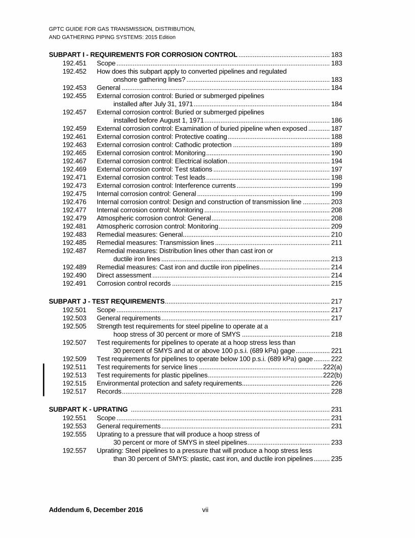
SUBPART I - REQUIREMENTS FOR CORROSION CONTROL ................................................... 183 192.451 Scope ....................................................................................................................... 183 192.452 How does this subpart apply to converted pipelines and regulated onshore gathering lines? ................................................................................ 183 192.453 General .................................................................................................................... 184 192.455 External corrosion control: Buried or submerged pipelines installed after July 31, 1971 ............................................................................ 184 192.457 External corrosion control: Buried or submerged pipelines installed before August 1, 1971 ...................................................................... 186 192.459 External corrosion control: Examination of buried pipeline when exposed ............ 187 192.461 External corrosion control: Protective coating ......................................................... 188 192.463 External corrosion control: Cathodic protection ...................................................... 189 192.465 External corrosion control: Monitoring ..................................................................... 190 192.467 External corrosion control: Electrical isolation ......................................................... 194 192.469 External corrosion control: Test stations ................................................................. 197 192.471 External corrosion control: Test leads ..................................................................... 198 192.473 External corrosion control: Interference currents .................................................... 199 192.475 Internal corrosion control: General .......................................................................... 199 192.476 Internal corrosion control: Design and construction of transmission line ............... 203 192.477 Internal corrosion control: Monitoring ...................................................................... 208 192.479 Atmospheric corrosion control: General .................................................................. 208 192.481 Atmospheric corrosion control: Monitoring .............................................................. 209 192.483 Remedial measures: General.................................................................................. 210 192.485 Remedial measures: Transmission lines ................................................................ 211 192.487 Remedial measures: Distribution lines other than cast iron or ductile iron lines .............................................................................................. 213 192.489 Remedial measures: Cast iron and ductile iron pipelines ....................................... 214 192.490 Direct assessment ................................................................................................... 214 192.491 Corrosion control records ........................................................................................ 215 SUBPART J - TEST REQUIREMENTS ............................................................................................ 217 192.501 Scope ....................................................................................................................... 217 192.503 General requirements .............................................................................................. 217 192.505 Strength test requirements for steel pipeline to operate at a hoop stress of 30 percent or more of SMYS ................................................. 218 192.507 Test requirements for pipelines to operate at a hoop stress less than 30 percent of SMYS and at or above 100 p.s.i. (689 kPa) gage ................... 221 192.509 Test requirements for pipelines to operate below 100 p.s.i. (689 kPa) gage ......... 222 192.511 Test requirements for service lines ..................................................................... 222(a) 192.513 Test requirements for plastic pipelines ................................................................ 222(b) 192.515 Environmental protection and safety requirements................................................. 226 192.517 Records .................................................................................................................... 228 SUBPART K - UPRATING ............................................................................................................... 231 192.551 Scope ....................................................................................................................... 231 192.553 General requirements .............................................................................................. 231 192.555 Uprating to a pressure that will produce a hoop stress of 30 percent or more of SMYS in steel pipelines .............................................. 233 192.557 Uprating: Steel pipelines to a pressure that will produce a hoop stress less than 30 percent of SMYS: plastic, cast iron, and ductile iron pipelines ......... 235
GPTC GUIDE FOR GAS TRANSMISSION, DISTRIBUTION, AND GATHERING PIPING SYSTEMS: 2015 Edition
Addendum 3, December 2015 viii
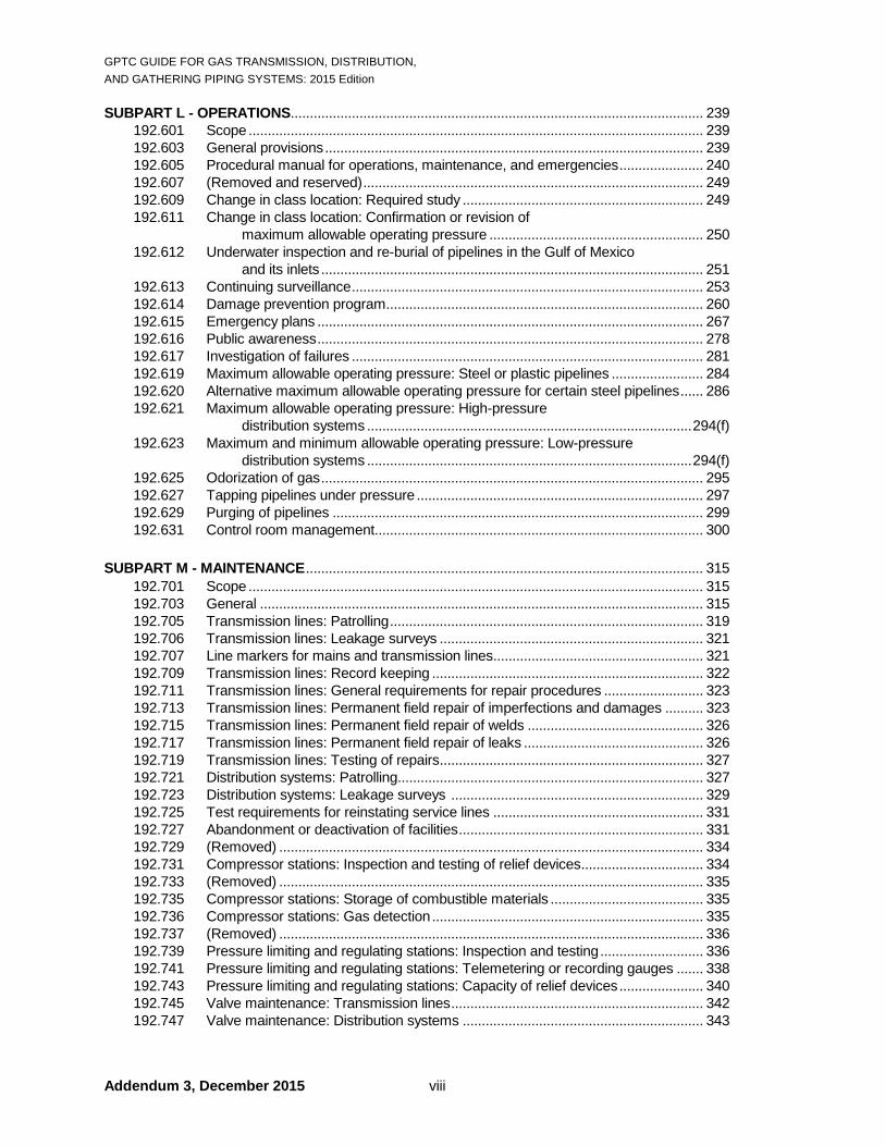
SUBPART L - OPERATIONS............................................................................................................ 239 192.601 Scope ....................................................................................................................... 239 192.603 General provisions ................................................................................................... 239 192.605 Procedural manual for operations, maintenance, and emergencies ...................... 240 192.607 (Removed and reserved) ......................................................................................... 249 192.609 Change in class location: Required study ............................................................... 249 192.611 Change in class location: Confirmation or revision of maximum allowable operating pressure ........................................................ 250 192.612 Underwater inspection and re-burial of pipelines in the Gulf of Mexico and its inlets .................................................................................................... 251 192.613 Continuing surveillance ............................................................................................ 253 192.614 Damage prevention program ................................................................................... 260 192.615 Emergency plans ..................................................................................................... 267 192.616 Public awareness ..................................................................................................... 278 192.617 Investigation of failures ............................................................................................ 281 192.619 Maximum allowable operating pressure: Steel or plastic pipelines ........................ 284 192.620 Alternative maximum allowable operating pressure for certain steel pipelines ...... 286 192.621 Maximum allowable operating pressure: High-pressure distribution systems ..................................................................................... 294(f) 192.623 Maximum and minimum allowable operating pressure: Low-pressure distribution systems ..................................................................................... 294(f) 192.625 Odorization of gas .................................................................................................... 295 192.627 Tapping pipelines under pressure ........................................................................... 297 192.629 Purging of pipelines ................................................................................................. 299 192.631 Control room management...................................................................................... 300 SUBPART M - MAINTENANCE ........................................................................................................ 315 192.701 Scope ....................................................................................................................... 315 192.703 General .................................................................................................................... 315 192.705 Transmission lines: Patrolling .................................................................................. 319 192.706 Transmission lines: Leakage surveys ..................................................................... 321 192.707 Line markers for mains and transmission lines....................................................... 321 192.709 Transmission lines: Record keeping ....................................................................... 322 192.711 Transmission lines: General requirements for repair procedures .......................... 323 192.713 Transmission lines: Permanent field repair of imperfections and damages .......... 323 192.715 Transmission lines: Permanent field repair of welds .............................................. 326 192.717 Transmission lines: Permanent field repair of leaks ............................................... 326 192.719 Transmission lines: Testing of repairs ..................................................................... 327 192.721 Distribution systems: Patrolling................................................................................ 327 192.723 Distribution systems: Leakage surveys .................................................................. 329 192.725 Test requirements for reinstating service lines ....................................................... 331 192.727 Abandonment or deactivation of facilities ................................................................ 331 192.729 (Removed) ............................................................................................................... 334 192.731 Compressor stations: Inspection and testing of relief devices ................................ 334 192.733 (Removed) ............................................................................................................... 335 192.735 Compressor stations: Storage of combustible materials ........................................ 335 192.736 Compressor stations: Gas detection ....................................................................... 335 192.737 (Removed) ............................................................................................................... 336 192.739 Pressure limiting and regulating stations: Inspection and testing ........................... 336 192.741 Pressure limiting and regulating stations: Telemetering or recording gauges ....... 338 192.743 Pressure limiting and regulating stations: Capacity of relief devices ...................... 340 192.745 Valve maintenance: Transmission lines .................................................................. 342 192.747 Valve maintenance: Distribution systems ............................................................... 343

GPTC GUIDE FOR GAS TRANSMISSION, DISTRIBUTION, AND GATHERING PIPING SYSTEMS: 2015 Edition
ix
192.749 Vault maintenance ................................................................................................... 344 192.751 Prevention of accidental ignition .............................................................................. 345 192.753 Caulked bell and spigot joints .................................................................................. 349 192.755 Protecting cast-iron pipelines................................................................................... 350 192.761 (Removed) ............................................................................................................... 350 SUBPART N - QUALIFICATION OF PIPELINE PERSONNEL ....................................................... 351 192.801 Scope ....................................................................................................................... 351 192.803 Definitions ................................................................................................................ 352 192.805 Qualification program ............................................................................................... 355 192.807 Recordkeeping ......................................................................................................... 361 192.809 General .................................................................................................................... 362 SUBPART O - GAS TRANSMISSION PIPELINE INTEGRITY MANAGEMENT ........................... 365 192.901 What do the regulations in this subpart cover? ....................................................... 365 192.903 What definitions apply to this subpart? .................................................................... 367 192.905 How does an operator identify a high consequence area? ..................................... 369 192.907 What must an operator do to implement this subpart? ........................................... 374 192.909 How can an operator change its integrity management program?......................... 377 192.911 What are the elements of an integrity management program? .............................. 378 192.913 When may an operator deviate its program from certain requirements of this subpart? ............................................................................................... 388 192.915 What knowledge and training must personnel have to carry out an integrity management program? .................................................................... 389 192.917 How does an operator identify potential threats to pipeline integrity and use the threat identification in its integrity program? .............................. 391 192.919 What must be in the baseline assessment plan? ................................................... 423 192.921 How is the baseline assessment to be conducted? ................................................ 428 192.923 How is direct assessment used and for what threats? ........................................... 432 192.925 What are the requirements for using External Corrosion Direct Assessment (ECDA)? .................................................................................... 433 192.927 What are the requirements for using Internal Corrosion Direct Assessment (ICDA)? ...................................................................................... 456 192.929 What are the requirements for using Direct Assessment for Stress Corrosion Cracking (SCCDA)? ...................................................................... 471 192.931 How may Confirmatory Direct Assessment (CDA) be used? ................................. 478 192.933 What actions must an operator take to address integrity issues? .......................... 481 192.935 What additional preventive and mitigative measures must an operator take?................................................................................................. 486 192.937 What is a continual process of evaluation and assessment to maintain a pipeline’s integrity? ....................................................................... 492 192.939 What are the required reassessment intervals? ..................................................... 495 192.941 What is a low stress reassessment? ....................................................................... 499 192.943 When can an operator deviate from these reassessment intervals? ..................... 501 192.945 What methods must an operator use to measure program effectiveness? ................................................................................................. 503 192.947 What records must an operator keep? ................................................................... 504 192.949 How does an operator notify PHMSA? .................................................................... 506 192.951 Where does an operator file a report? .................................................................... 507

GPTC GUIDE FOR GAS TRANSMISSION, DISTRIBUTION, AND GATHERING PIPING SYSTEMS: 2015 Edition
Addendum 3, December 2015 x
SUBPART P - GAS DISTRIBUTION PIPELINE INTEGRITY MANAGEMENT (IM) ...................... 509 192.1001 What definitions apply to this subpart? .................................................................... 509 192.1003 What do the regulations in this subpart cover? ....................................................... 509 192.1005 What must a gas distribution operator (other than a master meter or small LPG operator) do to implement this subpart? ...................................... 510 192.1007 What are the required elements of an integrity management (IM) plan? ............... 510 192.1009 What must an operator report when compression couplings fail? ......................... 512 192.1011 What records must an operator keep? ................................................................... 512 192.1013 When may an operator deviate from required periodic inspections under this part? ............................................................................................... 513 192.1015 What must a master meter or small liquefied petroleum gas (LPG) operator do to implement this subpart? ........................................................................ 514 APPENDICES TO PART 192 Appendix A (Removed and reserved) ................................................................................... 517 Appendix B Qualification of Pipe ........................................................................................... 519 Appendix C Qualification of Welders for Low Stress Level Pipe .......................................... 523 Appendix D Criteria for Cathodic Protection and Determination of Measurements ............. 527 Appendix E Guidance on Determining High Consequence Areas and on Carrying out Requirements in the Integrity Management Rule .................... 529 GUIDE MATERIAL APPENDICES Guide Material Appendix G-191-1 Telephonic notice worksheet ...................................... 537 Guide Material Appendix G-191-2 Distribution system incident report .............................. 539 Guide Material Appendix G-191-3 Distribution system annual report ............................... 541 Guide Material Appendix G-191-4 Distribution system mechanical fitting failure report........................................................ 543 Guide Material Appendix G-191-5 Transmission and gathering systems incident report ..................................................... 545 Guide Material Appendix G-191-6 Transmission and gathering systems annual report ...................................................... 547 Guide Material Appendix G-191-7 Determination of reporting requirements for safety-related conditions .............................. 549 Guide Material Appendix G-191-8 Safety-related condition report to United States Department of Transportation ............................ 551 Guide Material Appendix G-191-9 Calculating gas loss from a damaged pipeline ........... 553 Guide Material Appendix G-192-1 Summary of references and related sources ............. 557 Guide Material Appendix G-192-1A Editions of material specifications, codes and standards previously incorporated by reference in the Regulations .............................. 591 Guide Material Appendix G-192-2 Specified minimum yield strengths ............................. 595 Guide Material Appendix G-192-3 (Reserved) ................................................................... 599 Guide Material Appendix G-192-4 Rules for reinforcement of welded branch connections ........................................................ 603 Guide Material Appendix G-192-5 Pipe end preparation ................................................... 613 Guide Material Appendix G-192-6 Substructure damage prevention guidelines for directional drilling and other trenchless technologies ....................................................... 619 Guide Material Appendix G-192-7 Large-scale distribution outage response and recovery .............................................................. 621 Guide Material Appendix G-192-8 Distribution Integrity Management Program (DIMP) ................................................................ 625

GPTC GUIDE FOR GAS TRANSMISSION, DISTRIBUTION, AND GATHERING PIPING SYSTEMS: 2015 Edition
Addendum 6, December 2016
xi
Guide Material Appendix G-192-8A Distribution Integrity Management Program (DIMP), cross-references to relevant guide material ..................................................... 655
Guide Material Appendix G-192-9 Test conditions for pipelines other than service lines ............................................... 663 Guide Material Appendix G-192-9A Pressure testing guidelines for transmission integrity assessments ................... 665 Guide Material Appendix G-192-10 Test conditions for service lines .................................. 669 Guide Material Appendix G-192-11 Gas leakage control guidelines for natural gas systems ...................................... 671 Guide Material Appendix G-192-11A Gas leakage control guidelines for petroleum gas systems ................................. 695 Guide Material Appendix G-192-12 Planned shutdown ....................................................... 717 Guide Material Appendix G-192-13 Considerations to minimize damage by outside forces .................................................................. 721 Guide Material Appendix G-192-14 In-line inspection ......................................................... 725 Guide Material Appendix G-192-15 Design of uncased pipeline crossings of highways and railroads ....................................... 731 Guide Material Appendix G-192-15A Horizontal directional drilling (HDD) for steel pipelines ................................................ 735 Guide Material Appendix G-192-15B Horizontal directional drilling (HDD) for plastic pipe .................................................... 739 Guide Material Appendix G-192-16 Substructure damage prevention guidelines .............. 743 Guide Material Appendix G-192-17 Explicit requirements for reports, inspections, tests, written procedures, records and similar actions .............................................. 747 Guide Material Appendix G-192-18 Cast iron pipe .............................................................. 755 Guide Material Appendix G-192-19 Memorandum of understanding between the Department of Transportation and the Department of the Interior regarding outer continental shelf pipelines ...................... 759 Guide Material Appendix G-192-20 Fusion equipment maintenance/repair inspection form ..................................................................... 763 Guide Material Appendix G-192-21 Occupational Safety & Health Administration Letters ................................................................. 765 Guide Material Appendix G-192-M SI (metric) units ........................................................... 767 INDEX ............................................................................................................................................... 771 Form for Proposals on ANSI GPTC Z380.1 .................................................................. Last Page

GPTC GUIDE FOR GAS TRANSMISSION, DISTRIBUTION, AND GATHERING PIPING SYSTEMS: 2015 Edition
xii
Reserved

GPTC GUIDE FOR GAS TRANSMISSION, DISTRIBUTION, AND GATHERING PIPING SYSTEMS: 2015 Edition
Addendum 6, December 2016 xvii
GAS PIPING TECHNOLOGY COMMITTEE MEMBERSHIP1
Listed by Committee
Officers Leticia Quezada, Chair
Nicor Gas, An AGL Resources Company Lee Reynolds, 1st Vice Chair
NiSource Gas Distribution Philip Sher, 2nd Vice Chair
Philip Sher Pipeline Consultant Mike Bellman, Secretary American Gas Association
Main Body (Consensus) Purpose is to act as the final decision making body within the GPTC structure.
(Voting unless otherwise noted)
Leticia Quezada, Nicor Gas, An AGL Resources Co., Chair Lee Reynolds, NiSource Gas Distribution, 1st Vice Chair Philip Sher, Philip Sher Pipeline Consultant, 2nd Vice Chair Mike Bellman, American Gas Association, Secretary 2 Richard Abraham, Marathon Pipe Line LLC Glen Armstrong, EN Engineering Stephen Bateman, Long Beach Gas & Oil Frank Bennett, UGI Utilities, Inc. David Bull, ViaData LP DeWitt Burdeaux, FlexSteel Pipeline Technologies John Butler, EQT Midstream Robert Cadorin, TransCanada Corporation Willard Carey, Energy Experts International John Chin, TransCanada Corporation Amerigo Del Buono, Weldbend Corporation F. Roy Fleet, F. Roy Fleet, Inc. Mary Friend, Public Service Commission of West Virginia Steven Groeber, Gas Operations Consultant Richard Huriaux, Richard Huriaux, Consulting Engineer
Randy Knapp, Plastics Pipe Institute John Kottwitz, Missouri Public Service Commission Douglas Lee, KLJ Progress Solutions, LLC Jon Loker, Pipeline Safety Consultant George Lomax, Heath Consultants Incorporated John Lueders, DTE Gas Company James McKenzie, Atmos Energy Corporation Theron McLaren, U.S. Department of Transportation - PHMSA Robert Naper, Energy Experts International Joseph Opert, BGE, An Exelon Company Eugene Palermo, Palermo Plastics Pipe Consulting Kenneth Peters, Kinder Morgan Inc. Robert Schmidt, Canadoil Forge Patrick Seamands, Laclede Gas Company Walter Siedlecki, AEGIS Insurance Services, Inc. Richard Slagle, Southern Company Gas Jerome Themig, Ameren Illinois Ram Veerapaneni, DTE Gas Company Frank Volgstadt, Volgstadt & Associates
Executive Section Responsible for the expedient and efficient handling of the business of the GPTC in all routine and ongoing matters.
Lee Reynolds, NiSource Gas Distribution, Chair Mike Bellman, American Gas Association, Secretary 2 David Bull, ViaData LP Allan Clarke, Consultant Jon Loker, Pipeline Safety Consultant John Lueders, DTE Gas Company Joseph Opert, BGE, An Exelon Company Eugene Palermo, Palermo Plastics Pipe Consulting
Kenneth Peters, Kinder Morgan Inc. Leticia Quezada, Nicor Gas, An AGL Resources Company Patrick Seamands, Laclede Gas Company Philip Sher, Philip Sher Pipeline Consultant Richard Slagle, Southern Company Gas Jerome Themig, Ameren Illinois Ram Veerapaneni, DTE Gas Company
________________________ 1 Membership as of 11/14/16 2 Non voting

GPTC GUIDE FOR GAS TRANSMISSION, DISTRIBUTION, AND GATHERING PIPING SYSTEMS: 2015 Edition
Addendum 6, December 2016
xviii
Editorial Section Responsible for maintaining consistent format and high structural standards for Guide Material and in ANSI Technical Reports.
Jon Loker, Pipeline Safety Consultant, Chair Lane Miller, Pacific Gas and Electric Company, Secretary Richard Abraham, Marathon Pipe Line LLC Stephen Bateman, Long Beach Gas & Oil John Butler, EQT Midstream F. Roy Fleet, F. Roy Fleet, Inc. Steven Gauthier, Energy Experts International
Steven Groeber, Gas Operations Consultant John Groot, Southern California Gas Company John Kottwitz, Missouri Public Service Commission Christine Maynard, NiSource, Inc. Paul Oleksa, Oleksa and Associates, Inc. Patrick Seamands, Laclede Gas Company Ram Veerapaneni, DTE Gas Company
Liaison Section Responsible for presenting GPTC actions to the appropriate government bodies and other groups in an effective manner.
Joseph Opert, BGE, An Exelon Company, Chair Steven Troch, BGE, An Exelon Company
Regulations Section Responsible for developing GPTC responses to Notices of Proposed Rulemaking (NPRMs) and to other regulatory Notices.
Patrick Seamands, Laclede Gas Company, Chair Frank Bennett, UGI Utilities, Inc. David Bull, ViaData LP Allan Clarke, Consultant Gregory Goble, R.W. Lyall & Company, Inc.
James McKenzie, Atmos Energy Corporation Robert Naper, Energy Experts International Eugene Palermo, Palermo Plastics Pipe Consulting Steven Troch, BGE, An Exelon Company
Distribution Division Responsible for technical review of all materials and take appropriate action before the material goes to the Main Body.
John Lueders, DTE Gas Company, Chair Lane Miller, Pacific Gas and Electric Company, Secretary Richard Abraham, Marathon Pipe Line LLC Glen Armstrong, EN Engineering Randy Bareither, Avista Utilities Stephen Bateman, Long Beach Gas & Oil Andrew Benedict, Opvantek Inc. David Bonner, PECO Energy, An Exelon Company David Bull, ViaData LP Brian Camfield, PECO Energy, An Exelon Company Willard Carey, Energy Experts International Leo Cody, Liberty Utilities Mark Conners, UGI Utilities, Inc. Denise Dolezal, Metropolitan Utilities District Kalu Kelly Emeaba, National Transportation Safety Board John Erickson, American Public Gas Association Chris Foley, RCP Inc. Mark Forster, Southern California Gas Andy Fortier, NW Natural Anthony Fuhrman, Public Service Electric & Gas John Goetz, Meade
Steven Groeber, Gas Operations Consultant John Groot, Southern California Gas Company Steve Hurbanek, OMNIMETRIX Antoinette (Toni) Imad, Puget Sound Energy John Kottwitz, Missouri Public Service Commission Brent Koym, CenterPoint Energy Sean Lynn, Xcel Energy Inc. Thomas Marlow, Vectren Corporation Christine Maynard, NiSource, Inc. James McKenzie, Atmos Energy Corporation Theron McLaren, U.S. Department of Transportation - PHMSA Jeffrey Meyers, Black & Veatch Corporation Robert Naper, Energy Experts International Paul Oleksa, Oleksa and Associates, Inc. Joseph Opert, BGE, An Exelon Company Christopher Pioli, Jacobs Consultancy Jim Rutherford, Heath Consultants Incorporated Patrick Seamands, Laclede Gas Company Parashar Sheth, National Grid D. Kevin Shuttlesworth, NorthWestern Energy Walter Siedlecki, AEGIS Insurance Services, Inc.
(Continued)

GPTC GUIDE FOR GAS TRANSMISSION, DISTRIBUTION, AND GATHERING PIPING SYSTEMS: 2015 Edition
Addendum 6, December 2016
xix
Distribution Division (Continued)
Richard Slagle, Southern Company Gas David Spangler, Washington Gas Light Company Jerome Themig, Ameren Illinois Steven Troch, BGE, An Exelon Company
Erich Trombley, Southwest Gas Corporation Alfredo Ulanday, EN Engineering David Weber, Consultant William Wells, New Jersey Natural Gas Company
Manufacturers Division
Responsible for technical review of all materials and take appropriate action before the material goes to the Main Body Eugene Palermo, Palermo Plastics Pipe Consulting, Chair Frank Volgstadt, Volgstadt & Associates, Secretary Brandon Babe, Arkema Inc. DeWitt Burdeaux, FlexSteel Pipeline Technologies Heath Casteel, Performance Pipe Amerigo Del Buono, Weldbend Corporation Steven Gauthier, Energy Experts International Gregory Goble, R.W. Lyall & Company, Inc. Richard Huriaux, Consulting Engineer
James Johnston, McElroy Manufacturing, Inc. Randy Knapp, Plastics Pipe Institute George Lomax, Heath Consultants Incorporated William Luff, JANA Corp. Daniel O'Leary, Timberline Tool Barry Peterson, Performance Pipe Robert Schmidt, Canadoil Forge David Wartluft, Continental Industries
Transmission Division
Responsible for technical review of all materials and take appropriate action before the material goes to the Main Body. Kenneth Peters, Kinder Morgan Inc., Chair Robert Cadorin, TransCanada Corporation, Secretary Banu Acimis, State of CA, Public Utilities Commission - Representing NAPSR Erik Anderson, Northwestern Energy Aaron Bass, Interstate Energy Company Stephen Beatty, LG&E-KU, PPL Companies Robert Becken, Energy Experts International Frank Bennett, UGI Utilities, Inc. John Butler, EQT Midstream John Chin, TransCanada Corporation Allan Clarke, Consultant Rodney Dyck, U.S. Department of Transportation – PHMSA Michael Falk, Pacific Gas & Electric Robert Fassett, E2 Consulting Engineers F. Roy Fleet, F. Roy Fleet, Inc. Mary Friend, Public Service Commission of West Virginia
Narinder Grewal, AG Square, Inc. George Hamaty, Columbia Gas Transmission, LLC Steven Huntington, System One Services Douglas Lee, KLJ Progress Solutions Ray Lewis, ROSEN USA Jon Loker, Pipeline Safety Consultant Erin McKay, Hilcorp Alaska, LLC Alice Ratcliffe, Crestwood Midstream Timothy Strommen, WE Energies William Taylor, CenterPoint Energy David Terzian, National Grid Ram Veerapaneni, DTE Gas Company Jim Walton, JW’s Pipeline Integrity Services Ben Wasson, Alyeska Pipeline Svc. Co. Gary White, PI Confluence, Inc. Brian Wolf, Hatch Mott MacDonald
Damage Prevention / Emergency Response Task Group Responsible for developing Guide Material, ANSI Technical Reports, and other technical material as directed by the Main Body.
David Bull, ViaData LP, Chair Vacant - Secretary Richard Abraham, Marathon Pipe Line LLC Banu Acimis, State of CA PUC, NAPSR Rep. Glen Armstrong, EN Engineering Randy Bareither, Avista Utilities Stephen Bateman, Long Beach Gas & Oil Frank Bennett, UGI Utilities, Inc. Brian Camfield, PECO Energy Willard Carey, Energy Experts International John Chin, TransCanada Corporation Leo Cody, Liberty Utilities
Kalu Kelly Emeaba, National Transportation Safety Board John Erickson, American Public Gas Association Michael Falk, Pacific Gas & Electric F. Roy Fleet, F. Roy Fleet, Inc. Mark Forster, Southern California Gas Mary Friend, Public Service Commission of West Virginia Steven Groeber, Gas Operations Consultant George Hamaty, Columbia Gas Transmission Corp. Steve Hurbanek, OMNIMETRIX John Kottwitz, Missouri Public Service Commission George Lomax, Heath Consultants Incorporated Thomas Marlow, Vectren Corporation
(Continued)

GPTC GUIDE FOR GAS TRANSMISSION, DISTRIBUTION, AND GATHERING PIPING SYSTEMS: 2015 Edition
Addendum 6, December 2016
xx
Damage Prevention / Emergency Response Task Group (Continued) Christine Maynard, NiSource, Inc. Erin McKay, Hilcorp Alaska, LLC Robert Naper, Energy Experts International Daniel O’Leary, Timberline Tool Christopher Pioli, Jacobs Consultancy Alice Ratcliffe, Crestwood Midstream Patrick Seamands, Laclede Gas Company Kevin Shuttlesworth, NorthWestern Energy Walter Siedlecki, AEGIS Insurance Services, Inc. Richard Slagle, Southern Company Gas
David Spangler, Washington Gas Light Company Jerome Themig, Ameren Illinois Alfredo Ulanday, EN Engineering Ram Veerapaneni, DTE Gas Company Jim Walton, JW’s Pipeline Integrity Services David Wartluft, Continental Industries Benjamin Wasson, Alyeska Pipeline Service Company William Wells, New Jersey Natural Gas Company Brian Wolf, Hatch Mott MacDonald
Design Task Group
Responsible for developing Guide Material, ANSI Technical Reports, and other technical material as directed by the Main Body. Allan Clarke, Consultant, Chair James McKenzie, Atmos Energy Corporation Secretary Erik Anderson, Northwestern Energy Stephen Beatty, LG&E-KU, PPL Companies Robert Becken, Energy Experts International Andrew Benedict, Opvantek DeWitt Burdeaux, FlexSteel Pipeline Technologies John Butler, EQT Midstream Heath Casteel, Performance Pipe John Chin, TransCanada Corporation Mark Connors, UGI Utilities, Inc. Denise Dolezal, Metropolitan Utilities District Rodney Dyck, U.S. Department of Transportation - PHMSA Robert Fassett, E2 Consulting Engineers Chris Foley, RCP Inc. Andy Fortier, NW Natural Anthony Fuhrman, Public Service Electric & Gas Gregory Goble, R.W. Lyall & Company, Inc. Narinder Grewal, AG Square, Inc.
John Groot, Southern California Gas Company Richard Huriaux, Consulting Engineer Antoinette (Toni) Imad, Puget Sound Energy Randy Knapp, Plastics Pipe Institute Brent Koym, CenterPoint Energy Douglas Lee, KLJ Progress Solutions John Lueders, DTE Gas Company William Luff, JANA Corp. Theron McLaren, U.S. Department of Transportation - PHMSA Jeffrey Meyers, Black & Veatch Corporation Paul Oleksa, Oleksa and Associates, Inc. Eugene Palermo, Palermo Plastics Pipe Consulting Kenneth Peters, Kinder Morgan Inc. Robert Schmidt, Canadoil Forge Parashar Sheth, National Grid William Taylor, CenterPoint Energy David Terzian, National Grid Erich Trombley, Southwest Gas Corporation Frank Volgstadt, Volgstadt & Associates
Integrity Management / Corrosion Task Group
Responsible for developing Guide Material, ANSI Technical Reports, and other technical material as directed by the Main Body. Ram Veerapaneni, DTE Gas Company, Chair James McKenzie, Atmos Energy Corporation, Secretary Banu Acimis, State of CA, Public Utilities Commission - Representing NAPSR Glen Armstrong, EN Engineering Aaron Bass, Interstate Energy Company Frank Bennett, UGI Utilities, Inc. John Chin, TransCanada Corporation Allan Clarke, Consultant Kalu Kelly Emeaba, National Transportation Safety Board Robert Fassett, E2 Consulting Engineers Anthony Fuhrman, Public Service Electric & Gas Narinder Grewal, AG Square, Inc. Brent Koym, CenterPoint Energy Ray Lewis, ROSEN USA
Thomas Marlow, Vectren Corporation Theron McLaren, U.S. Department of Transportation - PHMSA Lane Miller, Pacific Gas and Electric Company Daniel O'Leary, Timberline Tool Paul Oleksa, Oleksa and Associates, Inc. Christopher Pioli, Jacobs Consultancy Timothy Strommen, WE Energies William Taylor, CenterPoint Energy Steven Troch, BGE, An Exelon Company Erich Trombley, Southwest Gas Corporation Jim Walton, JW’s Pipeline Integrity Services David Wartluft, Continental Industries Gary White, PI Confluence, Inc. Brian Wolf, Hatch Mott MacDonald

GPTC GUIDE FOR GAS TRANSMISSION, DISTRIBUTION, AND GATHERING PIPING SYSTEMS: 2015 Edition
Addendum 6, December 2016
xxi
Operations & Maintenance / Operator Qualification Task Group Jerome Themig, Ameren Illinois, Chair Douglas Lee, KLJ Progress Solutions, Secretary Erik Anderson, Northwestern Energy Randy Bareither, Avista Utilities Stephen Bateman, Long Beach Gas & Oil Stephen Beatty, LG&E-KU, PPL Companies Robert Becken, Energy Experts International Andrew Benedict, Opvantek Inc. David Bonner, PECO Energy, An Exelon Company David Bull, ViaData LP John Butler, EQT Midstream Robert Cadorin, TransCanada Corporation Brain Camfield, PECO Energy, An Exelon Company Willard Carey, Energy Experts International Leo Cody, Liberty Utilities Mark Connors, UGI Utilities, Inc. Denise Dolezal, Metropolitan Utilities District John Erickson, American Public Gas Association Michael Falk, Pacific Gas & Electric Chris Foley, RCP Inc. Mark Forster, Southern California Gas Mary Friend, Public Service Commission of West Virginia John Goetz, Meade
Steven Groeber, Gas Operations Consultant John Groot, Southern California Gas Company George Hamaty, Columbia Gas Transmission, LLC Steven Huntington, System One Services Antoinette (Toni) Imad, Puget Sound Energy James Johnston, McElroy Manufacturing, Inc. John Kottwitz, Missouri Public Service Commission George Lomax, Heath Consultants Incorporated John Lueders, DTE Gas Company Sean Lynn, Xcel Energy Inc. Christine Maynard, NiSource, Inc. Erin McKay, Hilcorp Alaska, LLC Robert Naper, Energy Experts International Joseph Opert, BGE, An Exelon Company Kenneth Peters, Kinder Morgan Inc. Alice Ratcliffe, Crestwood Midstream Jim Rutherford, Heath Consultants Incorporated D. Kevin Shuttlesworth, NorthWestern Energy Walter Siedlecki, AEGIS Insurance Services, Inc. David Spangler, Washington Gas Light Company Alfredo Ulanday, EN Engineering Benjamin Wasson, Alyeska Pipeline Service Company William Wells, New Jersey Natural Gas Company
Plastic Task Group Responsible for developing Guide Material, ANSI Technical Reports, and other technical material as directed by the Main Body.
Richard Slagle, Southern Company Gas, Chair Frank Volgstadt, Volgstadt & Associates, Secretary Glen Armstrong, EN Engineering Brandon Babe, Arkema Inc. DeWitt Burdeaux, FlexSteel Pipeline Technologies Heath Casteel, Performance Pipe Gregory Goble, R.W. Lyall & Company, Inc. Richard Huriaux, Consulting Engineer James Johnston, McElroy Manufacturing, Inc.
Randy Knapp, Plastics Pipe Institute William Luff, JANA Corp. Jeffrey Meyers, Black & Veatch Corporation Lane Miller, Pacific Gas and Electric Company Eugene Palermo, Palermo Plastics Pipe Consulting Barry Peterson, Performance Pipe Patrick Seamands, Laclede Gas Company Parashar Sheth, National Grid David Weber, Consultant
Committee Scope The Gas Piping Technology Committee (GPTC) is an independent technical group of individuals with expertise in, and concern for, natural gas pipeline safety and is responsible for:
• Developing and maintaining the Guide for Gas Transmission, Distribution, and Gathering Piping Systems (Guide), an American National Standards Institute (ANSI) Standard, that contains information and methods to assist a natural gas pipeline operator (operator) in complying with the Code of Federal Regulations "Transportation of Natural and Other Gas by Pipeline: Title 49, Subchapter D - Pipeline Safety - Part 191 - Annual Reports, Incident Reports, and Safety-Related Condition Reports; and Part 192 - Minimum Federal Safety Standards" by providing "how to" information related to the standards. Guide material is advisory in nature. Operators may use the guide material or other equally acceptable methods of compliance with the Federal Regulations.
• Developing and maintaining ANSI Technical Reports regarding the application of natural gas pipeline technology and operating or maintenance practices.
• Promoting the use of voluntary consensus standards.

GPTC GUIDE FOR GAS TRANSMISSION, DISTRIBUTION, AND GATHERING PIPING SYSTEMS: 2015 Edition
Addendum 3, December 2015 xxii
• Petitioning the United States Department of Transportation (DOT) for changes in Federal Natural Gas Pipeline Safety Regulations based on the technical expertise of the GPTC.
• When deemed appropriate by the Main Body, commenting on Advanced Notice of Proposed Rulemakings, Notice of Proposed Rulemakings, Final Rules, and other regulatory notices issued by DOT involving such regulations.
• Reviewing applicable National Transportation Safety Board (NTSB) reports, DOT and State Pipeline Safety Agency incident reports, and taking appropriate action including that of responding to recommendations issued to the GPTC.
• Taking such actions that are necessary and proper to further the safe application of natural gas pipeline technology.

GPTC GUIDE FOR GAS TRANSMISSION, DISTRIBUTION, AND GATHERING PIPING SYSTEMS: 2015 Edition
Addendum 5, July 2016 xxiii
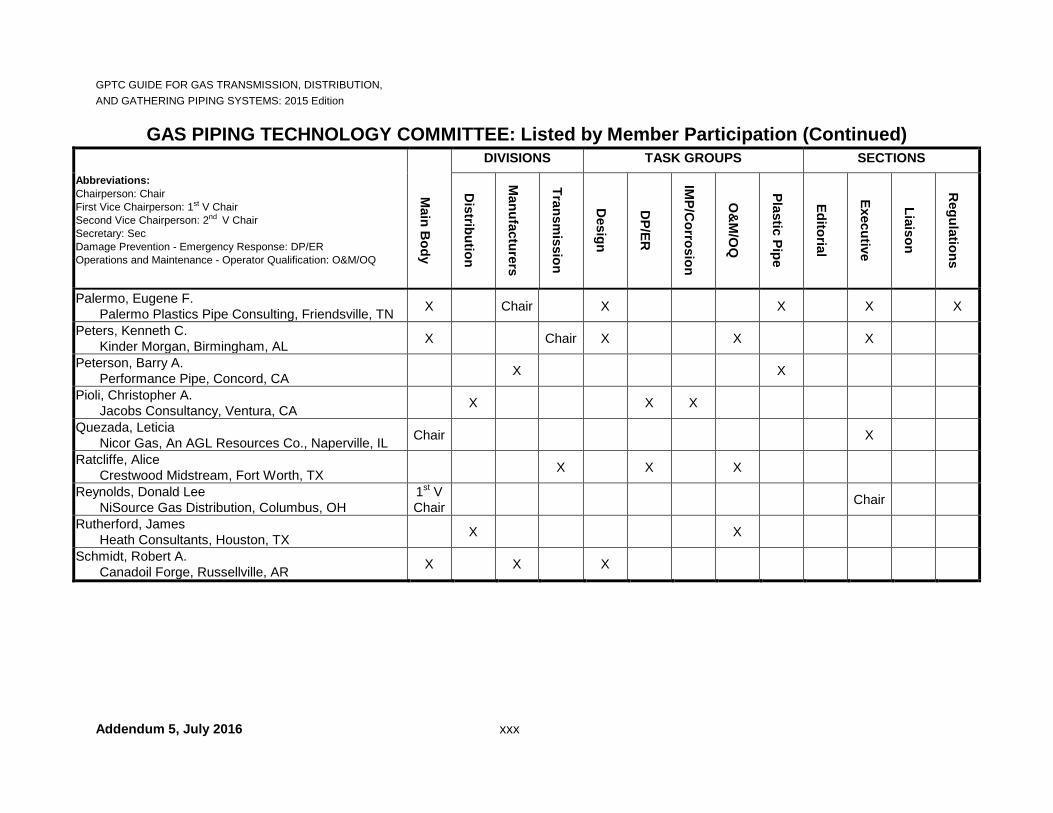
GAS PIPING TECHNOLOGY COMMITTEE: Listed by Member Participation DIVISIONS TASK GROUPS SECTIONS Abbreviations: Chairperson: Chair First Vice Chairperson: 1st V Chair Second Vice Chairperson: 2nd V Chair Secretary: Sec Damage Prevention - Emergency Response: DP/ER Operations and Maintenance - Operator Qualification: O&M/OQ
M
ain Body
D
istribution
M
anufacturers
Transm
ission
D
esign
D
P/ER
IM
P/Corrosion
O
&M
/OQ
Plastic Pipe
Editorial
Executive
Liaison
R
egulations
Abraham, Richard A. Marathon Pipe Line LLC, Findlay, OH X X X X
Acimis, Banu State of CA, PUC/NAPSR, Sacramento, CA X X X
Anderson, Erik Northwestern Energy, Butte, MT X X X
Armstrong, Glen F. EN Engineering, Warrenville, IL X X X X X
Babe, Brandon Arkema, King of Prussia, PA X X
Bareither, Randy K. Avista Utilities, Spokane, WA X X X
Bass, Aaron G. Interstate Energy Company, Pottstown, PA X X
Bateman, Stephen C. Long Beach Gas & Oil, Long Beach, CA X X X X X
Beatty, Stephen A. Louisville Gas & Electric, Louisville, KY X X X
Becken, Robert C. Energy Experts International, Pleasant Hill, CA X X X
Bellman, Mike American Gas Association, Washington, DC Sec Sec

GPTC GUIDE FOR GAS TRANSMISSION, DISTRIBUTION, AND GATHERING PIPING SYSTEMS: 2015 Edition
Addendum 6, December 2016 xxiv
GAS PIPING TECHNOLOGY COMMITTEE: Listed by Member Participation (Continued) DIVISIONS TASK GROUPS SECTIONS Abbreviations: Chairperson: Chair First Vice Chairperson: 1st V Chair Second Vice Chairperson: 2nd V Chair Secretary: Sec Damage Prevention - Emergency Response: DP/ER Operations and Maintenance - Operator Qualification: O&M/OQ
M
ain Body
D
istribution
M
anufacturers
Transm
ission
D
esign
D
P/ER
IM
P/Corrosion
O
&M
/OQ
Plastic Pipe
Editorial
Executive
Liaison
R
egulations
Benedict, Andrew G. Opvantek, Inc., Newtown, PA X X X
Bennett, Frank M. UGI Utilities, Reading, PA X X X X X
Bonner, David T. PECO Energy, An Exelon Company, Philadelphia, PA
X X
Bull, David E. ViaData LP, Noblesville, IN X X Chair X X X
Burdeaux, DeWitt FlexSteel Pipeline Technologies, Houston, TX X X X X
Butler, John EQT Midstream, Charleston, WV X X X X X
Cadorin, Robert J. TransCanada Corp., Troy, MI X Sec X
Camfield, Brian PECO Energy, An Exelon Company, Philadelphia, PA
X X X
Carey, Willard S. Energy Experts International, Neptune, NJ X X X X
Casteel, Heath W. Performance Pipe, Plano, TX X X X

GPTC GUIDE FOR GAS TRANSMISSION, DISTRIBUTION, AND GATHERING PIPING SYSTEMS: 2015 Edition
Addendum 6, December 2016 xxv
GAS PIPING TECHNOLOGY COMMITTEE: Listed by Member Participation (Continued) DIVISIONS TASK GROUPS SECTIONS Abbreviations: Chairperson: Chair First Vice Chairperson: 1st V Chair Second Vice Chairperson: 2nd V Chair Secretary: Sec Damage Prevention - Emergency Response: DP/ER Operations and Maintenance - Operator Qualification: O&M/OQ
M
ain Body
D
istribution
M
anufacturers
Transm
ission
D
esign
D
P/ER
IM
P/Corrosion
O
&M
/OQ
Plastic Pipe
Editorial
Executive
Liaison
R
egulations
Chin, John S. TransCanada Corp., Troy, MI X X X X X
Clarke, Allan M. Consultant, Katy, TX X Chair X X X
Cody, Leo T. Liberty Utilities, Salem, NH X X X
Conners, Mark C. UGI Utilities, Reading, PA X X X
Del Buono, Amerigo J. Weldbend Corp., League City, TX X X
Dolezal, Denise L. Metropolitan Utilities District, Omaha, NE X X X
Dyck, Rodney I.J. PHMSA, Washington, DC X X
Emeaba, Kalu Kelly NTSB, Washington, DC X X X
Erickson, John P. American Public Gas Association, Washington, DC X X X
Falk, Michael Pacific Gas & Electric, San Ramon, CA X X X
Fassett, Robert P. E2 Consulting Engineers, Emeryville, CA X X X

GPTC GUIDE FOR GAS TRANSMISSION, DISTRIBUTION, AND GATHERING PIPING SYSTEMS: 2015 Edition
Addendum 6, December 2016 xxvi
GAS PIPING TECHNOLOGY COMMITTEE: Listed by Member Participation (Continued) DIVISIONS TASK GROUPS SECTIONS Abbreviations: Chairperson: Chair First Vice Chairperson: 1st V Chair Second Vice Chairperson: 2nd V Chair Secretary: Sec Damage Prevention - Emergency Response: DP/ER Operations and Maintenance - Operator Qualification: O&M/OQ
M
ain Body
D
istribution
M
anufacturers
Transm
ission
D
esign
D
P/ER
IM
P/Corrosion
O
&M
/OQ
Plastic Pipe
Editorial
Executive
Liaison
R
egulations
Fleet, F. Roy F. Roy Fleet, Inc., Westmont, IL X X X X
Foley, Chris RCP Inc., Houston, TX X X X
Forster, Mark Southern California Gas, Los Angeles, CA X X X
Fortier, Andy M. NW Natural, Portland, OR X X
Friend, Mary S. WV PSC, Charleston, WV / NAPSR X X X X
Fuhrman, Anthony Public Service Electric & Gas, Newark, NJ X X X
Gauthier, Steven W. Energy Experts International, Inverness, IL X X
Goble, Gregory H. R. W. Lyall & Co., Corona, CA X X X X
Goetz, John Meade, McCook, IL X X
Grewal, Narinder AG Square, Inc., Sugar Grove, IL X X X

GPTC GUIDE FOR GAS TRANSMISSION, DISTRIBUTION, AND GATHERING PIPING SYSTEMS: 2015 Edition
Addendum 5, July 2016 xxvii
GAS PIPING TECHNOLOGY COMMITTEE: Listed by Member Participation (Continued) DIVISIONS TASK GROUPS SECTIONS Abbreviations: Chairperson: Chair First Vice Chairperson: 1st V Chair Second Vice Chairperson: 2nd V Chair Secretary: Sec Damage Prevention - Emergency Response: DP/ER Operations and Maintenance - Operator Qualification: O&M/OQ
M
ain Body
D
istribution
M
anufacturers
Transm
ission
D
esign
D
P/ER
IM
P/Corrosion
O
&M
/OQ
Plastic Pipe
Editorial
Executive
Liaison
R
egulations
Groeber, Steven A. Gas Operations Consultant, Cinnaminson, NJ X X X X X
Groot, John M. Southern California Gas, Los Angeles, CA X X X X
Hamaty, George Columbia Gas Transmission Corp., Charleston, WV X X X
Huntington, Steven System One Services, Pittsburgh, PA X X
Hurbanek, Stephen F. OMNIMETRIX, Buford, GA X X
Huriaux, Richard D. Consulting Engineer, Baltimore, MD X X X X
Imad, Antoninette Puget Sound Energy, Bellevue, WA X X X
Johnston Jr., James S. McElroy Manufacturing, Inc., Tulsa, OK X X X
Knapp, Randy Plastics Pipe Institute, Irving, TX X X X X
GPTC GUIDE FOR GAS TRANSMISSION, DISTRIBUTION, AND GATHERING PIPING SYSTEMS: 2015 Edition
Addendum 6, December 2016 xxviii
GAS PIPING TECHNOLOGY COMMITTEE: Listed by Member Participation (Continued) DIVISIONS TASK GROUPS SECTIONS Abbreviations: Chairperson: Chair` First Vice Chairperson: 1st V Chair Second Vice Chairperson: 2nd V Chair Secretary: Sec Damage Prevention - Emergency Response: DP/ER Operations and Maintenance - Operator Qualification: O&M/OQ
M
ain Body
D
istribution
M
anufacturers
Transm
ission
D
esign
D
P/ER
IM
P/Corrosion
O
&M
/OQ
Plastic Pipe
Editorial
Executive
Liaison
R
egulations
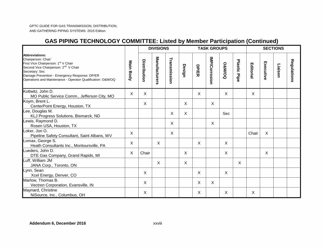
Kottwitz, John D. MO Public Service Comm., Jefferson City, MO X X X X X
Koym, Brent L. CenterPoint Energy, Houston, TX X X X
Lee, Douglas M. KLJ Progress Solutions, Bismarck, ND X X Sec
Lewis, Raymond D. Rosen USA, Houston, TX X X
Loker, Jon O. Pipeline Safety Consultant, Saint Albans, WV X X Chair X
Lomax, George S. Heath Consultants Inc., Montoursville, PA X X X X
Lueders, John D. DTE Gas Company, Grand Rapids, MI X Chair X X X
Luff, William JM JANA Corp., Toronto, ON X X X
Lynn, Sean Xcel Energy, Denver, CO X X X
Marlow, Thomas B. Vectren Corporation, Evansville, IN X X X
Maynard, Christine NiSource, Inc., Columbus, OH X X X X

GPTC GUIDE FOR GAS TRANSMISSION, DISTRIBUTION, AND GATHERING PIPING SYSTEMS: 2015 Edition
Addendum 6, December 2016 xxix
GAS PIPING TECHNOLOGY COMMITTEE: Listed by Member Participation (Continued) DIVISIONS TASK GROUPS SECTIONS Abbreviations: Chairperson: Chair First Vice Chairperson: 1st V Chair Second Vice Chairperson: 2nd V Chair Secretary: Sec Damage Prevention - Emergency Response: DP/ER Operations and Maintenance - Operator Qualification: O&M/OQ
M
ain Body
D
istribution
M
anufacturers
Transm
ission
D
esign
D
P/ER
IM
P/Corrosion
O
&M
/OQ
Plastic Pipe
Editorial
Executive
Liaison
R
egulations
McKay, Erin Hilcorp Alaska, LLC, Anchorage, AK X X X
McKenzie, James E. Atmos Energy Corp., Jackson, MS X X Sec Sec X
McLaren, Theron C. (Chris) PHMSA , Washington, DC X X X X
Meyers, Jeffrey Black & Veatch Corporation, Knoxville, TN X X X
Miller, D. Lane PG&E Company, San Ramon, CA Sec X X Sec
Naper, Robert C. Energy Experts International, Canton, MA X X X X X
O’Leary, Daniel Timberline Tool, Kalispell, MT X X X
Oleksa, Paul E. Oleksa & Assoc., Broadview Heights, OH X X X X
Opert, Joseph BGE, An Exelon Company, Baltimore, MD X X X X Chair
GPTC GUIDE FOR GAS TRANSMISSION, DISTRIBUTION, AND GATHERING PIPING SYSTEMS: 2015 Edition
Addendum 5, July 2016 xxx
GAS PIPING TECHNOLOGY COMMITTEE: Listed by Member Participation (Continued) DIVISIONS TASK GROUPS SECTIONS Abbreviations: Chairperson: Chair First Vice Chairperson: 1st V Chair Second Vice Chairperson: 2nd V Chair Secretary: Sec Damage Prevention - Emergency Response: DP/ER Operations and Maintenance - Operator Qualification: O&M/OQ
M
ain Body
D
istribution
M
anufacturers
Transm
ission
D
esign
D
P/ER
IM
P/Corrosion
O
&M
/OQ
Plastic Pipe
Editorial
Executive
Liaison
R
egulations
Palermo, Eugene F. Palermo Plastics Pipe Consulting, Friendsville, TN X Chair X X X X
Peters, Kenneth C. Kinder Morgan, Birmingham, AL X Chair X X X
Peterson, Barry A. Performance Pipe, Concord, CA X X
Pioli, Christopher A. Jacobs Consultancy, Ventura, CA X X X
Quezada, Leticia Nicor Gas, An AGL Resources Co., Naperville, IL Chair X
Ratcliffe, Alice Crestwood Midstream, Fort Worth, TX X X X
Reynolds, Donald Lee NiSource Gas Distribution, Columbus, OH
1st V Chair Chair
Rutherford, James Heath Consultants, Houston, TX X X
Schmidt, Robert A. Canadoil Forge, Russellville, AR X X X

GPTC GUIDE FOR GAS TRANSMISSION, DISTRIBUTION, AND GATHERING PIPING SYSTEMS: 2015 Edition
Addendum 5, July 2015 xxxi
GAS PIPING TECHNOLOGY COMMITTEE: Listed by Member Participation (Continued) DIVISIONS TASK GROUPS SECTIONS Abbreviations: Chairperson: Chair First Vice Chairperson: 1st V Chair Second Vice Chairperson: 2nd V Chair Secretary: Sec Damage Prevention - Emergency Response: DP/ER Operations and Maintenance - Operator Qualification: O&M/OQ
M
ain Body
D
istribution
M
anufacturers
Transm
ission
D
esign
D
P/ER
IM
P/Corrosion
O
&M
/OQ
Plastic Pipe
Editorial
Executive
Liaison
R
egulations
Seamands, Patrick A. Laclede Gas Co., St. Louis, MO X X X X X X Chair
Sher, Philip Philip Sher Pipeline Consultant, Cheshire, CT
2nd V Chair X
Sheth, Parashar National Grid, Hicksville, NY X X X
Shuttlesworth, D. Kevin NorthWestern Energy, Sioux Falls, SD X X X
Siedlecki, Walter V. AEGIS Insurance Services, Inc., East Rutherford, NJ X X X X
Slagle, Richard L. Southern Company Gas, Atlanta, GA X X X Chair X
Spangler, David Washington Gas Light Co., Springfield, VA X X X
Strommen, Timothy D. WE Energies, Milwaukee, WI X X
Taylor, William E. CenterPoint Energy, Shreveport, LA X X X
Terzian, David National Grid, Waltham, MA X X
Themig, Jerome S. Ameren Illinois Utilities, Springfield, IL X X X Chair X
Troch, Steven J. BGE, An Exelon Company, Baltimore, MD X X X X

GPTC GUIDE FOR GAS TRANSMISSION, DISTRIBUTION, AND GATHERING PIPING SYSTEMS: 2015 Edition
Addendum 5, July 2016 xxxii
GAS PIPING TECHNOLOGY COMMITTEE: Listed by Member Participation (Continued)
DIVISIONS TASK GROUPS SECTIONS Abbreviations: Chairperson: Chair First Vice Chairperson: 1st V Chair Second Vice Chairperson: 2nd V Chair Secretary: Sec Damage Prevention - Emergency Response: DP/ER Operations and Maintenance - Operator Qualification: O&M/OQ
M
ain Body
D
istribution
M
anufacturers
Transm
ission
D
esign
D
P/ER
IM
P/Corrosion
O
&M
/OQ
Plastic Pipe
Editorial
Executive
Liaison
R
egulations
Trombley, Erich D. Southwest Gas Corp., Las Vegas, NV X X X
Ulanday, Alfredo (Fred) S. EN Engineering, Warrenville, IL X X X
Veerapaneni, Ram DTE Gas Company, Detroit, MI X X X Chair X X
Volgstadt, Frank R. Volgstadt & Associates, Madison, OH X Sec X Sec
Walton, Jim JW’s Pipeline Integrity Services, Carrollton, TX X X X
Wartluft, David C. Continental Industries, Broken Arrow, OK X X X
Wasson, Ben Alyeska Pipeline Service Co. Anchorage, AK X X X
Weber, David E. Consulting Engineer, Barnstable, MA X X
Wells, William M. New Jersey Natural Gas Co., Wall, NJ X X X
White, Gary R. PI Confluence, Inc., Humble, TX X X
Wolf, Brian Hatch Mott MacDonald, Holyoke, MA X X X

GPTC GUIDE FOR GAS TRANSMISSION, DISTRIBUTION, AND GATHERING PIPING SYSTEMS: 2015 Edition
xxxiii
LETTER TO GAS PIPING TECHNOLOGY COMMITTEE FROM THE U.S. DEPARTMENT OF TRANSPORTATION

GPTC GUIDE FOR GAS TRANSMISSION, DISTRIBUTION, AND GATHERING PIPING SYSTEMS: 2015 Edition
xxxiv
AMERICAN GAS ASSOCIATION (AGA) NOTICE AND DISCLAIMER
This document was developed through a voluntary consensus standards development process via the American National Standards Institute (ANSI) ANSI Essential Requirements Due process requirement for American National Standards (Edition January 2014). While AGA administers the process and establishes rules to promote fairness in the development of consensus, it does not write the document and it does not independently test, evaluate, or verify the accuracy or completeness of any information or the soundness of any judgments contained in this publication. The AGA disclaims liability for any personal injury, property or other damages of any nature whatsoever, whether special, indirect, consequential or compensatory, directly or indirectly resulting from this publication, use of, or reliance on this publication. The AGA also makes no guaranty or warranty as to the accuracy or completeness of any information published herein. In issuing and making this document available, the AGA is not undertaking to render professional or other services for or on behalf of any person or entity. Nor is the AGA undertaking to perform any duty owed by any person or entity to someone else. Anyone using this document should rely on his or her own independent judgment or, as appropriate, seek the advice of a competent professional in determining the exercise of reasonable care in any given circumstances. The AGA has no power, nor does it undertake, to police or enforce compliance with the contents of this document. Nor does the AGA list, certify, test, or inspect products, designs, or installations for compliance with this document. Any certification or other statement of compliance with the requirements of this document shall not be attributable to the AGA and is solely the responsibility of the certifier or maker of the statement. The AGA does not take any position with respect to the validity of any patent rights asserted in connection with any items which are mentioned in or are the subject of this publication, and the AGA disclaims liability for the infringement of any patent resulting from the use of or reliance on it. Users of this publication are expressly advised that determination of the validity of any such patent rights, and the risk of infringement of such rights, is entirely their own responsibility. Users of this publication should consult applicable federal, state, and local laws and regulations. The AGA does not, through this publication, provide legal advice for any purpose or intend to urge action that is not in compliance with applicable laws, and this publication may not be construed as doing so. Changes to this document may become necessary from time to time. If changes are believed appropriate by any person or entity, such suggested changes should be communicated to AGA in writing using the form found at the end of the document titled, Form For Proposals on ANSI GPTC Z380.1 and sent to: American Gas Association, ATTN: Secretariat GPTC Z380, 400 North Capitol Street, NW, Suite 450, Washington, DC 20001, U.S.A. Suggested changes must include: contact information, including name, address and any corporate affiliation; full name of the document; suggested revisions to the text of the document; the rationale for the suggested revisions; and permission to use the suggested revisions in an amended publication of the document.

GPTC GUIDE FOR GAS TRANSMISSION, DISTRIBUTION, AND GATHERING PIPING SYSTEMS: 2015 Edition
xxxv
EDITORIAL CONVENTIONS OF THE GUIDE
Practices Used in the Guide ♦ If the guide material does not cover all the specific elements in a section of the Federal Regulations
(Regulation(s)), and there is no editorial note, no other guide material has been deemed necessary by the Gas Piping Technology Committee (Committee).
♦ The term "includes" does not limit any list to those items presented and means, "includes but not limited
to." This term is used in the same manner as it is used in the Regulations (reference §192.15). Further, added qualifiers such as "may" or "might" are sometimes used to emphasize that a list is not intended to set a minimum requirement or practice.
♦ The term "should" indicates recommendations that are not mandatory, but are to be acted upon as
appropriate. As such, this guide material is advisory in nature, and operators may use it (or other equally acceptable methods) for a regulatory compliance aid.
♦ All figures and tables located in the basic guide material are designated by the corresponding Regulation
section number followed by a capital letter for figures (sequentially), or lower case Roman numeral for tables (e.g., FIGURE 192.485A or TABLE 192.485i).
♦ The date shown in the title block for each section is the effective date of the original Regulation or its
latest amendment. ♦ Sections of the Regulations that have been deleted are not listed by title in the Contents unless reserved
by the Regulations. However, the section numbers have been retained in the Guide, along with their effective date of removal (e.g., §192.57, Removed and reserved. [Effective 03/08/89]).
♦ Sections of the Regulations having a future effective date may be presented for both the current and
new requirements and with the effective date emphasized. In such case, the guide material is subject to review in light of the new requirements.
Common Notes in the Guide
♦ No guide material necessary. In the opinion of the Committee, the Regulation section is self-
explanatory and no additional information is provided. ♦ No guide material available at present. The Committee has not issued guide material or has not yet
determined if guide material is necessary. ♦ This guide material is under review following Amendment (either 19x-yy or control number). The
Committee is currently reviewing the amendment. ♦ Discontinued or Withdrawn. Where either of these words accompanies a listing of an industry
standard or other published reference, it indicates that the document is no longer current or has been withdrawn, and may not be available from its original source. The document may be available from an alternate source. When using such a document, care should be taken to determine the validity of the material and the reason for which it was discontinued or withdrawn.
♦ See §19x.xxx, refers to Regulation Section 19x.xxx and the guide material directly beneath it.

GPTC GUIDE FOR GAS TRANSMISSION, DISTRIBUTION, AND GATHERING PIPING SYSTEMS: 2015 Edition
xxxvi
♦ See x of the guide material under §19y.yyy. This refers to Section x of the guide material directly beneath §19y.yyy.
♦ See x above (or below). This refers to Section x of the guide material in which the reference appears.

GPTC GUIDE FOR GAS TRANSMISSION, DISTRIBUTION, AND GATHERING PIPING SYSTEMS: 2015 Edition
Addendum 6, December 2016 xlvii
HISTORICAL RECONSTRUCTION OF PART 192 (Continued)
Part 192 Subpart
Part 192 Section
Effective Date of Original Version if other than 11/12/70
Amendments (if any)
SUBPART G – 192.301 GENERAL 192.303 CONSTRUCTION 192.305 192-120 REQUIREMENTS FOR 192.307 TRANSMISSION 192.309 192-3, 192-85, 192-88 LINES AND MAINS 192.311 192-93 192.313 192-26, 192-29, 192-49, 192-85 192.315 192-85 192.317 192-27, 192-78 192.319 192-27, 192-78, 192-85 192.321 192-78, 192-85, 192-93, 192-94 192.323 192.325 192-85 192.327 192-27, 192-78, 192-85, 192-98 192.328 12/22/08 RIN 2137-AE25
SUBPART H – 192.351 CUSTOMER METERS, 192.353 192-85, 192-93 SERVICE 192.355 192-58 REGULATORS, AND 192.357 SERVICE LINES 192.359 192-3, 192-85 192.361 192-75, 192-85, 192-93 192.363 192.365 192.367 192-75 192.369 192.371 192-3, 192-85 192.373 192-85 192.375 192-78 192.377 192.379 11/03/72 192-8 192.381 07/22/96 192-79, 192-80, 192-85, 192-121 192.383
192.385 02/03/98 04/17/17
192-83, 192-113, 192-116, 192-121 192-121

GPTC GUIDE FOR GAS TRANSMISSION, DISTRIBUTION, AND GATHERING PIPING SYSTEMS: 2015 Edition
xlviii
HISTORICAL RECONSTRUCTION OF PART 192 (Continued)
Part 192 Subpart
Part 192 Section
Effective Date of Original Version if other than 11/12/70
Amendments (if any)
SUBPART I – 192.451 08/01/71 192-4, 192-27, 192-33 REQUIREMENTS FOR 192.452 12/30/77 192-30, 192-102 CORROSION 192.453 08/01/71 192-4, 192-71 CONTROL 192.455 08/01/71 192-4, 192-28, 192-39, 192-78,
192-85 192.457 08/01/71 192-4, 192-33, 192-93 192.459 08/01/71 192-4, 192-87 192.461 08/01/71 192-4 192.463 08/01/71 192-4 192.465 08/01/71 192-4, 192-27, 192-33, 192-35,
192-35A, 192-85, 192-93, 192-114 192.467 08/01/71 192-4, 192-33 192.469 08/01/71 192-4, 192-27 192.471 08/01/71 192-4 192.473 08/01/71 192-4, 192-33 192.475 08/01/71 192-4, 192-33, 192-78, 192-85 192.476 05/23/07 RIN 2137-AE09 192.477 08/01/71 192-4, 192-33 192.479 08/01/71 192-4, 192-33, 192-93 192.481 08/01/71 192-4, 192-27, 192-33, 192-93 192.483 08/01/71 192-4 192.485 08/01/71 192-4, 192-33, 192-78, 192-88,
192-119 192.487 08/01/71 192-4, 192-88 192.489 08/01/71 192-4 192.490 10/25/05 192-101 192.491 08/01/71 192-4, 192-33, 192-78

GPTC GUIDE FOR GAS TRANSMISSION, DISTRIBUTION, AND GATHERING PIPING SYSTEMS: 2015 Edition
Addendum 6, December 2016 lxxiii
HISTORICAL RECORD OF AMENDMENTS TO PART 192 (Continued)
Amdt 192-
Subject Vol FR Pg# Published Date
Docket or RIN No.
Effective Date
Affected Sections 192.
119 Periodic Updates of Regulatory References to Technical Standards and Miscellaneous Amendments
80 FR 168 01/05/15 RIN 2137-AE85
03/06/15 7, 11, 55, 59, 63, 65, 112, 113, 123, 145, 147, 153, 163, 165, 177, 189, 191, 225, 227, 229, 241, 281, 283, 485, 735, 903, 923, 925, 931, 933,
935, 939, App. B
119 Correction 80 FR 46847 08/06/15 RIN 2137-AE85
08/06/15 11, 55, 153, 191, 735, 923, 933,
App. B
120 Miscellaneous Changes to Pipeline Safety Regulations
80 FR 12762 03/11/15 RIN 2137-AE59
10/01/15 3, 9, 65, 112, 153, 165, 225, 227, 229, 241, 243, 285, 305, 503, 505, 620, 805,
925, 949
120 Response to Petitions for Reconsideration
80 FR 58633 09/30/15 RIN 2137-AE59
Delayed indefinitely
on 09/30/15
305
121 Expanding the Use of Excess Flow Valves
81 FR 70987 10/14/16 RIN 2137-AE71
04/14/17 381, 383, 385
121 Correction 81 FR 72739 10/21/16 RIN 2137-AE71
04/14/17 383
* Issued as a Direct Final Rule (DFR) or Interim Final Rule.

GPTC GUIDE FOR GAS TRANSMISSION, DISTRIBUTION, AND GATHERING PIPING SYSTEMS: 2015 Edition
lxxiv
Reserved

GPTC GUIDE FOR GAS TRANSMISSION, DISTRIBUTION, §191.1 AND GATHERING PIPING SYSTEMS: 2015 Edition
Addendum 1, May 2015 1
PART 191
ANNUAL REPORTS, INCIDENT REPORTS, AND SAFETY-RELATED CONDITION REPORTS
Authority: 49 U.S.C. 5121, 60102, 60103, 60104, 60108, 60117, 60118, 60124, 60132, and 49 CFR 1.97. Source: Originally 35 FR 317, Jan. 8, 1970; currently Amdt. 191-23, 80 FR 12762, Mar. 11, 2015.
§191.1 Scope.
[Effective Date: 01/01/11]
(a) This part prescribes requirements for the reporting of incidents, safety-related conditions, annual pipeline summary data by operators of gas pipeline facilities located in the United States or Puerto Rico, including pipelines within the limits of the Outer Continental Shelf as that term is defined in the Outer Continental Shelf Lands Act (43 U.S.C. 1331). (b) This part does not apply to— (1) Offshore gathering of gas in State waters upstream from the outlet flange of each facility where hydrocarbons are produced or where produced hydrocarbons are first separated, dehydrated, or otherwise processed, whichever facility is farther downstream; (2) Pipelines on the Outer Continental Shelf (OCS) that are producer-operated and cross into State waters without first connecting to a transporting operator’s facility on the OCS, upstream (generally seaward) of the last valve on the last production facility on the OCS. Safety equipment protecting PHMSA-regulated pipeline segments is not excluded. Producing operators for those pipeline segments upstream of the last valve of the last production facility on the OCS may petition the Administrator, or designee, for approval to operate under PHMSA regulations governing pipeline design, construction, operation, and maintenance under 49 CFR 190.9. (3) Pipelines on the Outer Continental Shelf upstream of the point at which operating responsibility transfers from a producing operator to a transporting operator; or (4) Onshore gathering of gas— (i) Through a pipeline that operates at less than 0 psig (0 kPa); (ii) Through a pipeline that is not a regulated onshore gathering line (as determined in §192.8 of this subchapter); and (iii) Within inlets of the Gulf of Mexico, except for the requirements in §192.612. [Amdt. 191-5, 49 FR 18956, May 3, 1984; Amdt. 191-6, 53 FR 24942, July 1, 1988 with Amdt. 191-6 Correction, 53 FR 26560, July 13, 1988; Amdt. 191-11, 61 FR 27789, June 3, 1996 with Amdt. 191-11 Correction, 61 FR 45905, Aug. 30, 1996; Amdt. 191-12, 62 FR 61692, Nov. 19, 1997 with Amdt. 191-12 Confirmation, 63 FR 12659, Mar. 16, 1998; Amdt. 191-15, 68 FR 46109, Aug. 5, 2003; RIN 2137-AD77, 70 FR 11135, Mar. 8, 2005; Amdt. 191-21, 75 FR 72878, Nov. 26, 2010]
GUIDE MATERIAL (a) For offshore pipelines, responsibilities have been assigned to the Department of Transportation and the
Department of the Interior in accordance with their Memorandum of Understanding dated December 10, 1996 (Implemented per Federal Register, Vol. 62, No. 223, November 19, 1997). See Guide Material Appendix G-192-19.

GPTC GUIDE FOR GAS TRANSMISSION, DISTRIBUTION, §191.1 AND GATHERING PIPING SYSTEMS: 2015 Edition
Addendum 6, December 2016 2
(b) State regulations may be more stringent and require additional reporting for operators of intrastate pipelines. A NAPSR document (1st Edition 2011) provides a compendium of these additional state requirements and is available at www.napsr.org.
(c) The Occupational Safety and Health Administration has issued letters regarding application of their standards to working conditions that are regulated by PHMSA-OPS. See Guide Material Appendix G-192-21.
§191.3 Definitions.
[Effective Date: 01/01/11]
As used in this part and the PHMSA Forms referenced in this part— Administrator means the Administrator, Pipeline and Hazardous Materials Safety Administration or his or her delegate. Gas means natural gas, flammable gas, or gas which is toxic or corrosive; Incident means any of the following events: (1) An event that involves a release of gas from a pipeline, or of liquefied natural gas, liquefied petroleum gas, refrigerant gas, or gas from an LNG facility, and that results in one or more of the following consequences: (i) A death, or personal injury necessitating in-patient hospitalization; (ii) Estimated property damage of $50,000 or more, including loss to the operator and others, or both, but excluding cost of gas lost; (iii) Unintentional estimated gas loss of three million cubic feet or more; (2) An event that results in an emergency shutdown of an LNG facility. Activation of an emergency shutdown system for reasons other than an actual emergency does not constitute an incident. (3) An event that is significant in the judgment of the operator, even though it did not meet the criteria of paragraphs (1) or (2) of this definition. LNG facility means a liquefied natural gas facility as defined in §193.2007 of part 193 of this chapter; Master Meter System means a pipeline system for distributing gas within, but not limited to, a definable area, such as a mobile home park, housing project, or apartment complex, where the operator purchases metered gas from an outside source for resale through a gas distribution pipeline system. The gas distribution pipeline system supplies the ultimate consumer who either purchases the gas directly through a meter or by other means, such as by rents; Municipality means a city, count or any other political subdivision of a state; Offshore means beyond the line of ordinary low water along that portion of the coast of the United States that is in direct contact with the open seas and beyond the line marking the seaward limit of inland waters; Operator means a person who engages in the transportation of gas; Outer Continental Shelf means all submerged lands lying seaward and outside the area of lands beneath navigable waters as defined in Section 2 of the Submerged Lands Act (43 U.S.C. 1301) and of which the subsoil and seabed appertain to the United States and are subject to its jurisdiction and control. Person means any individual, firm, joint venture, partnership, corporation, association, state, municipality, cooperative association, or joint stock association, and includes any trustee, receiver, assignee, or personal representative thereof; Pipeline or Pipeline System means all parts of those physical facilities through which gas moves in transportation, including, but not limited to, pipe, valves, and other appurtenance attached to pipe, compressor units, metering stations, regulator stations, delivery stations, holders, and fabricated assemblies.

GPTC GUIDE FOR GAS TRANSMISSION, DISTRIBUTION, §191.3 AND GATHERING PIPING SYSTEMS: 2015 Edition
3
State includes each of the several states, the District of Columbia, and the Commonwealth of Puerto Rico; Transportation of gas means the gathering, transmission, or distribution of gas by pipeline, or the storage of gas in or affecting interstate or foreign commerce. [Amdt. 191-5, 49 FR 18956, May 3, 1984; Amdt. 191-10, 61 FR 18512, Apr. 26, 1996; Amdt. 191-12, 62 FR 61692, Nov. 19, 1997 with Amdt. 191-12 Confirmation, 63 FR 12659, Mar. 16, 1998; RIN 2137-AD43, 68 FR 11748, Mar. 12, 2003; RIN 2137-AD77, 70 FR 11135, Mar. 8, 2005; Amdt. 191-21, 75 FR 72878, Nov. 26, 2010]
GUIDE MATERIAL ADDITIONAL INCIDENT CONSIDERATIONS (a) State regulations may be more stringent and require additional reporting for operators of intrastate
pipelines. (b) "In-patient hospitalization" means hospital admission and at least one overnight stay. (c) Estimated property damage includes, but is not limited to, costs due to: (1) Property damage to operator's facilities and property of others. (2) Facility repair and replacement. (3) Restoration of gas distribution service and relighting customers. (4) Leak locating. (5) Right-of-way cleanup. (6) Environmental cleanup and damage. (d) Items to be considered when determining if an event may be significant include the following. (1) Rupture or explosion. (2) Fire. (3) Loss of service. (4) Evacuation of people in the area. (5) Involvement of local emergency response personnel.
(6) Degree of media involvement. (e) For guidance on calculating gas loss from a damaged pipeline, see Guide Material Appendix G-191-9.
§191.5 Immediate notice of certain incidents.
[Effective Date: 01/01/11]
(a) At the earliest practicable moment following discovery, each operator shall give notice in accordance with paragraph (b) of this section of each incident as defined in §191.3. (b) Each notice required by paragraph (a) of this section must be made to the National Response Center either by telephone to 800–424–8802 (in Washington, DC, 202 267–2675) or electronically at http://www.nrc.uscg.mil and must include the following information: (1) Names of operator and person making report and their telephone numbers. (2) The location of the incident. (3) The time of the incident. (4) The number of fatalities and personal injuries, if any. (5) All other significant facts that are known by the operator that are relevant to the cause of the incident or extent of the damages.

GPTC GUIDE FOR GAS TRANSMISSION, DISTRIBUTION, §191.5 AND GATHERING PIPING SYSTEMS: 2015 Edition
Amendment 1, May 2015 4
[Amdt. 191-1, 36 FR 7507, Apr. 21, 1971; Amdt. 191-4, 47 FR 32719, July 29, 1982; Amdt. 191-5, 49 FR 18956, May 3, 1984; Amdt. 191-8, 54 FR 40878, Oct. 4, 1989; Amdt. 191-21, 75 FR 72878, Nov. 26, 2010]
GUIDE MATERIAL (a) Complete information is not necessary for the initial electronic or telephonic incident report to National
Response Center (NRC). Refer to Guide Material Appendix G-191-1 for a sample worksheet that may be used to compile information for the incident report. The initial incident report should be made within 2 hours of discovery of the incident. Initial report information should include the following.
(1) Name, address, and a 24-hour telephone number of the operator. An operator should consider providing a telephone number where more detailed information can be obtained.
(2) Time and date of incident. (3) Location of incident, provided in a manner that will aid agencies in locating the site on maps. GPS
coordinates, addresses and ZIP codes, and cross streets are useful. (4) Facilities involved. (5) Number of fatalities or injuries, if known. (6) Estimate of property damage. (7) Type of product released, and an estimate of the quantity released. For guidance on calculating
gas loss from a damaged pipeline, see Guide Material Appendix G-191-9. (8) Evacuations, if known. (9) The responsible party, if known. (10) Weather conditions at the incident site. (b) If an incident report has been made and further investigation reveals that the event was not an "incident,"
and therefore not reportable, the report should be nullified with a letter. This letter should be sent to the Information Resources Manager at the address specified in §191.7 within 30 days of the event. The letter should reference the NRC incident report number issued when the initial notification was made and briefly explain why the incident report is being nullified. Incident reports cannot be removed from the database, but the letter may help ensure accurate PHMSA-OPS records.
(c) Operators should consider making an additional report if there is a significant change in the data
previously provided to the NRC. A significant change may include an increase or decrease in the number of injuries or fatalities previously reported, or a revised estimate of property damage that is at least 10 times that previously reported. Consideration should be given to making an additional report up to 48 hours following the initial report. The operator should clearly report to the NRC that additional information is being provided and give the NRC the initial report’s assigned NRC Report Number. However, any report following the initial report will result in an additional NRC Report Number being created for the same event. All related NRC Report Numbers should be referenced in the PHMSA-OPS electronic or written incident report (see §§191.9 and 191.15).
(d) For intrastate pipelines, it is necessary to comply with federal reporting requirements even though an
"incident" has been reported to the appropriate state agency.
§191.7 Report submission requirements.
▌[Effective Date: 10/01/15]
(a) General. Except as provided in paragraphs (b) and (e) of this section, an operator must submit each report required by this part electronically to the Pipeline and Hazardous Materials Safety Administration at http://portal.phmsa.dot.gov/pipeline unless an alternative reporting method is
GPTC GUIDE FOR GAS TRANSMISSION, DISTRIBUTION, §192.1 AND GATHERING PIPING SYSTEMS: 2015 Edition SUBPART A
Addendum 6, December 2016 17
PART 192
MINIMUM FEDERAL SAFETY STANDARDS
Authority: 49 U.S.C. 5103, 60102, 60104, 60108, 60109, 60110, 60113, 60116, 60118, 60137; and 49 CFR 1.97.
Source: Originally 35 FR 13248, Aug. 19, 1970; currently Amdt. 192-120, 80 FR 12762, Mar. 11, 2015.
SUBPART A GENERAL
§192.1 What is the scope of this part?
[Effective Date: 03/05/07]
(a) This part prescribes minimum safety requirements for pipeline facilities and the transportation of gas, including pipeline facilities and the transportation of gas within the limits of the outer continental shelf as that term is defined in the Outer Continental Shelf Lands Act (43 U.S.C. 1331). (b) This part does not apply to— (1) Offshore gathering of gas in State waters upstream from the outlet flange of each facility where hydrocarbons are produced or where produced hydrocarbons are first separated, dehydrated, or otherwise processed, whichever facility is farther downstream; (2) Pipelines on the Outer Continental Shelf (OCS) that are producer-operated and cross into State waters without first connecting to a transporting operator’s facility on the OCS, upstream (generally seaward) of the last valve on the last production facility on the OCS. Safety equipment protecting PHMSA-regulated pipeline segments is not excluded. Producing operators for those pipeline segments upstream of the last valve of the last production facility on the OCS may petition the Administrator, or designee, for approval to operate under PHMSA regulations governing pipeline design, construction, operation, and maintenance under 49 CFR 190.9; (3) Pipelines on the Outer Continental Shelf upstream of the point at which operating responsibility transfers from a producing operator to a transporting operator; (4) Onshore gathering of gas— (i) Through a pipeline that operates at less than 0 psig (0 kPa); (ii) Through a pipeline that is not a regulated onshore gathering line (as determined in §192.8); and (iii) Within inlets of the Gulf of Mexico, except for the requirements in §192.612; or (5) Any pipeline system that transports only petroleum gas or petroleum gas/air mixtures to— (i) Fewer than 10 customers, if no portion of the system is located in a public place; or (ii) A single customer, if the system is located entirely on the customer’s premises (no matter if a portion of the system is located in a public place). [Amdt. 192-27, 41 FR 34598, Aug. 16, 1976; Amdt. 192-67, 56 FR 63764, Dec. 5, 1991; Amdt. 192-78, 61 FR 28770, June 6, 1996 with Amdt. 192-78 Correction, 61 FR 30824, June 18, 1996; Amdt. 192-81, 62 FR 61692, Nov. 19, 1997 with Amdt. 192-81 Confirmation, 63 FR 12659, Mar. 16, 1998; Amdt. 192-92, 68

GPTC GUIDE FOR GAS TRANSMISSION, DISTRIBUTION, §192.1 AND GATHERING PIPING SYSTEMS: 2015 Edition SUBPART A
Addendum 6, December 2016 18
FR 46109, Aug. 5, 2003; RIN 2137-AD77, 70 FR 11135, Mar. 8, 2005; Amdt. 192-102, 71 FR 13289, Mar. 15, 2006; Amdt. 192-103, 72 FR 4655, Feb. 1, 2007]
GUIDE MATERIAL (a) The guide material presented in this Guide includes information and some acceptable methods to assist
the operator in complying with the Minimum Federal Safety Standards. The recommendations contained in the Guide are based on sound engineering principles, developed by a committee balanced in accordance with accepted committee procedures, and must be applied by the use of sound and competent engineering judgment. The guide material is advisory in nature and should not restrict the operator from using other methods of complying. In addition, the operator is cautioned that the guide material may not be adequate under all conditions encountered.
(b) While the GPTC Guide is intended principally to guide operators of natural gas pipelines, it is a valuable
reference for operators of other pipelines covered by Part 192. The user is cautioned that the unique properties and characteristics associated with other gases (e.g., toxicity, density, corrosivity, and temperature extremes) may require special engineering, operations, and maintenance considerations. Also, the unique properties and toxicity of other gases can represent significant hazards that need to be considered but are not specifically addressed in the Guide. Operators of petroleum gas distribution systems may benefit from information provided in the "Training Guide for Operators of Small LP Gas Systems" (also referred to as "Guidance Manual") available at www.phmsa.dot.gov/pipeline/tq/manuals.
(c) As used in the Guide, the terms Personnel, Employees, and Workers refer to operator employees and,
unless specifically noted otherwise, include other personnel used by operators to perform Part 192 functions.
(d) The operator is responsible for the work of a contractor performing tasks covered under Part 192. The
operator should ensure that contract personnel are familiar with applicable procedures prior to the start of work.
(e) A reference for hydrogen pipelines is OPS Report No. DOT.RSPA/DMT-10-85-1, "Safety Criteria for the
Operation of Gaseous Hydrogen Pipelines," (Discontinued). (f) For offshore pipelines, responsibilities have been assigned to the Department of Transportation and the
Department of the Interior in accordance with their Memorandum of Understanding dated December 10, 1996 (Implemented per Federal Register, Vol. 62, No. 223, November 19, 1997). See Guide Material Appendix G-192-19.
(g) Additional state requirements may exist for intrastate facilities. A NAPSR document (1st Edition 2011)
provides a compendium of these additional state requirements and is available at www.napsr.org. (h) The Occupational Safety and Health Administration has issued letters regarding application of their
standards to working conditions that are regulated by PHMSA-OPS. See Guide Material Appendix G-192-21.
§192.3 Definitions.
▌[Effective Date: 10/01/15]
As used in this part: Abandoned means permanently removed from service. Active corrosion means continuing corrosion that, unless controlled, could result in a condition that is detrimental to public safety.

GPTC GUIDE FOR GAS TRANSMISSION, DISTRIBUTION, §192.3 AND GATHERING PIPING SYSTEMS: 2015 Edition SUBPART A
19
Administrator means the Administrator, Pipeline and Hazardous Materials Safety Administration or his or her delegate. Alarm means an audible or visible means of indicating to the controller that equipment or processes are outside operator-defined, safety-related parameters. Control room means an operations center staffed by personnel charged with the responsibility for remotely monitoring and controlling a pipeline facility. Controller means a qualified individual who remotely monitors and controls the safety-related operations of a pipeline facility via a SCADA system from a control room, and who has operational authority and accountability for the remote operational functions of the pipeline facility. Customer meter means the meter that measures the transfer of gas from an operator to a consumer. Distribution line means a pipeline other than a gathering or transmission line. Electrical survey means a series of closely spaced pipe-to-soil readings over pipelines which are subsequently analyzed to identify locations where a corrosive current is leaving the pipeline. Exposed underwater pipeline means an underwater pipeline where the top of the pipe protrudes above the underwater natural bottom (as determined by recognized and generally accepted practices) in waters less than 15 feet (4.6 meters) deep, as measured from mean low water. Gas means natural gas, flammable gas, or gas which is toxic or corrosive. Gathering line means a pipeline that transports gas from a current production facility to a transmission line or main. Gulf of Mexico and its inlets means the waters from the mean high water mark of the coast of the Gulf of Mexico and its inlets open to the sea (excluding rivers, tidal marshes, lakes and canals) seaward to include the territorial sea and Outer Continental Shelf to a depth of 15 feet (4.6 meters), as measured from the mean low water. Hazard to navigation means, for the purposes of this part, a pipeline where the top of the pipe is less than 12 inches (305 millimeters) below the underwater natural bottom (as determined by recognized and generally accepted practices) in waters less than 15 feet (4.6 meters) deep, as measured from the mean low water. High pressure distribution system means a distribution system in which the gas pressure in the main is higher than the pressure provided to the customer. Line section means a continuous run of transmission line between adjacent compressor stations, between a compressor station and storage facilities, between a compressor station and a block valve, or between adjacent block valves. Listed specification means a specification listed in section I of Appendix B of this part. Low-pressure distribution system means a distribution system in which the gas pressure in the main is substantially the same as the pressure provided to the customer. Main means a distribution line that serves as a common source of supply for more than one service line. Maximum actual operating pressure means the maximum pressure that occurs during normal operations over a period of 1 year. Maximum allowable operating pressure (MAOP) means the maximum pressure at which a pipeline or segment of a pipeline may be operated under this part. Municipality means a city, county, or any other political subdivision of a state. Offshore means beyond the line of ordinary low water along that portion of the coast of the United States that is in direct contact with the open seas and beyond the line marking the seaward limit of inland waters. Operator means a person who engages in the transportation of gas. Outer Continental Shelf means all submerged lands lying seaward and outside the area of lands beneath navigable waters as defined in Section 2 of the Submerged Lands Act (43 U.S.C. 1301) and of which the subsoil and seabed appertain to the United States and are subject to its jurisdiction and control. Person means any individual, firm, joint venture, partnership, corporation, association, state, municipality, cooperative association, or joint stock association, and including any trustee, receiver, assignee, or personal representative thereof.

GPTC GUIDE FOR GAS TRANSMISSION, DISTRIBUTION, §192.3 AND GATHERING PIPING SYSTEMS: 2015 Edition SUBPART A
Addendum 1, May 2015 20
Petroleum gas means propane, propylene, butane, (normal butane or isobutanes), and butylene (including isomers), or mixtures composed predominantly of these gases, having a vapor pressure not exceeding 208 psi (1434 kPa) gage at 100 oF (38 oC). Pipe means any pipe or tubing used in the transportation of gas, including pipe-type holders. Pipeline means all parts of those physical facilities through which gas moves in transportation, including pipe, valves, and other appurtenance attached to pipe, compressor units, metering stations, regulator stations, delivery stations, holders, and fabricated assemblies. Pipeline environment includes soil resistivity (high or low), soil moisture (wet or dry), soil contaminants that may promote corrosive activity, and other known conditions that could affect the probability of active corrosion. Pipeline facility means new and existing pipelines, rights-of-way, and any equipment, facility, or building used in the transportation of gas or in the treatment of gas during the course of transportation. Service line means a distribution line that transports gas from a common source of supply to an individual customer, to two adjacent or adjoining residential or small commercial customers, or to multiple residential or small commercial customers served through a meter header or manifold. A service line ends at the outlet of the customer meter or at the connection to a customer's piping, whichever is further downstream, or at the connection to customer piping if there is no meter. Service regulator means the device on a service line that controls the pressure of gas delivered from a higher pressure to the pressure provided to the customer. A service regulator may serve one customer or multiple customers through a meter header or manifold. SMYS means specified minimum yield strength is: (1) For steel pipe manufactured in accordance with a listed specification, the yield strength specified as a minimum in that specification; or (2) For steel pipe manufactured in accordance with an unknown or unlisted specification, the yield strength determined in accordance with §192.107(b). State means each of the several states, the District of Columbia, and the Commonwealth ofPuerto Rico. Supervisory Control and Data Acquisition (SCADA) system means a computer-based system or systems used by a controller in a control room that collects and displays information about a pipeline facility and may have the ability to send commands back to the pipeline facility. Transmission line means a pipeline, other than a gathering line, that: (1) Transports gas from a gathering line or storage facility to a distribution center, storage facility, or large volume customer that is not down-stream from a distribution center; (2) operates at a hoop stress of 20 percent or more of SMYS; or (3) transports gas within a storage field. Note: A large volume customer may receive similar volumes of gas as a distribution center, and includes factories, power plants, and institutional users of gas. Transportation of gas means the gathering, transmission, or distribution of gas by pipeline or the storage of gas, in or affecting interstate or foreign commerce. Welder means a person who performs manual or semi-automatic welding. Welding operator means a person who operates machine or automatic welding equipment. [Amdt. 192-13, 38 FR 9083, Apr. 10, 1973; Amdt. 192-27, 41 FR 34598, Aug. 16, 1976; Amdt. 192-58, 53 FR 1633, Jan. 21, 1988; Amdt. 192-67, 56 FR 63764, Dec. 5, 1991; Amdt. 192-72, 59 FR 17275, Apr. 12, 1994 with Amdt. 192-72 Ext., 59 FR 49896, Sept. 30, 1994, Amdt. 192-72 Ext. Correction, 59 FR 52863, Oct. 19, 1994 and Amdt. 192-72 Ext., 60 FR 7133, Feb. 7, 1995; Amdt. 192-78, 61 FR 28770, June 6, 1996 with Amdt. 192-78 Correction, 61 FR 30824, June 18, 1996; Amdt. 192-81, 62 FR 61692, Nov. 19, 1997 with Amdt. 192-81 Confirmation, 63 FR 12659, Mar. 16, 1998; Amdt. 192-85, 63 FR 37500, July 13, 1998; Amdt. 192-89, 65 FR 54440, Sept. 8, 2000; RIN 2137-AD43, 68 FR 11748, Mar. 12, 2003; Amdt. 192-93, 68 FR 53895, Sept. 15, 2003; Amdt. 192-94, 69 FR 32886, June 14, 2004 with Amdt. 192-94 Correction, 69 FR 54591, Sept. 9, 2004 and Amdt. 192-94 DFR [Correction], 70 FR 3147, Jan. 21, 2005; Amdt. 192-98, 69 FR 48400, Aug. 10, 2004; RIN 2137-AD77, 70 FR 11135, Mar. 8, 2005; Amdt. 192-112, 74 FR 63310, Dec. 3, 2009; Amdt. 192-114, 75 FR 48593, Aug. 11, 2010; Amdt. 192-120, 80 FR 12762, Mar. 11, 2015]
GPTC GUIDE FOR GAS TRANSMISSION, DISTRIBUTION, §192.3 AND GATHERING PIPING SYSTEMS: 2015 Edition SUBPART A
Addendum 6, December 2016 21
GUIDE MATERIAL
Glossary of Commonly Used Terms (For Glossary of Commonly Used Abbreviations, see Table 192.3i below.)
Abandoned pipeline is a pipeline that is physically separated from its source of gas and is no longer
maintained under Part 192. Abandonment is the process of abandoning a pipeline. Adhesive joint is a joint made in thermosetting plastic piping by the use of an adhesive substance that forms
a bond between the mating surfaces without dissolving either one of them. Ambient temperature is the temperature of the surrounding medium, usually used to refer to the temperature
of the air in which a structure is situated or a device operates. See also Ground Temperature and Temperature.
Bell-welded pipe is furnace-welded pipe that has a longitudinal butt joint that is forge-welded by the mechanical pressure developed in drawing the furnace-heated skelp through a cone-shaped die. The die, commonly known as a "welding bell," serves as a combined forming and welding die. This type of pipe is produced in individual lengths from cut-length skelp. Typical specifications: ASTM A53, API Spec 5L. See also Furnace-butt-welded pipe and Pipe manufacturing processes.
Bottle is a gastight structure that is (1) completely fabricated by the manufacturer from pipe with integral drawn, forged, or spun end closures; and (2) tested in the manufacturer's plant. See also Bottle-type holder.
Bottle-type holder is any bottle or group of interconnected bottles installed in one location, and used for the sole purpose of storing gas. See also Bottle.
Carbon steel. By common custom, steel is considered to be carbon steel where (i) no minimum content is specified or required for aluminum, boron, chromium, cobalt, columbium, molybdenum, nickel, titanium, tungsten, vanadium, zirconium, or any other element added to obtain a desired alloying effect; (ii) the specified minimum content for copper does not exceed 0.40 percent; or (iii) the specified maximum content does not exceed 1.65 percent for manganese, 0.60 percent for silicon or 0.60 percent for copper.
All carbon steels may contain small quantities of unspecified residual elements unavoidably retained
from raw materials. These elements (copper, nickel, molybdenum, chromium, etc.) are considered incidental and are not normally determined or reported.
Cast iron. The unqualified term cast iron applies to gray-cast iron that is a cast ferrous material in which a major part of the carbon content occurs as free carbon in the form of flakes interspersed through the metal.
Cold-expanded pipe is seamless or welded pipe that is formed and then, expanded in the pipe mill while cold, so that the circumference is permanently increased by at least 0.50 percent.
Compressor station is a pipeline facility installed for the purpose of mechanically increasing the gas pressure on a pipeline system or for reducing back-pressure on upstream gas facilities to enhance flow. Other facilities that might be located at the same site but not actually part of the compressor station include measurement, treatment, processing, and pressure control.
Continuous-welded pipe is furnace-welded pipe which has a longitudinal butt joint that is forge-welded by the mechanical pressure developed in rolling the hot-formed skelp through a set of round pass welding rolls. It is produced in continuous lengths from coiled skelp and subsequently cut into individual lengths. Typical specifications (see §192.7): ASTM A53, API Spec 5L. See also Furnace-butt-welded pipe and Pipe manufacturing processes.
Control piping is pipe, valves, and fittings used to interconnect air, gas, or hydraulically operated control apparatus.
Copper Tube Size (CTS) is an alphanumeric sizing convention for copper or plastic components comprised of the letters CTS preceded by a dimensionless number (e.g., ½ CTS). The CTS "size" is indirectly related to the nominal outside diameter used in the design of copper tubing (§192.125) or plastic tubing (§192.121). In all cases, the actual nominal outside diameter, using the CTS sizing convention, will measure 1/8 inch greater than the nominal CTS size. For example, ½ CTS tubing has an actual nominal

GPTC GUIDE FOR GAS TRANSMISSION, DISTRIBUTION, §192.3 AND GATHERING PIPING SYSTEMS: 2015 Edition SUBPART A
22
outside diameter of 0.625 inches (0.500 + 0.125 inch). Curb valve is a type of service-line valve installed for the purpose of shutting off gas supply. It is typically
installed below grade at or near the property line. Deactivation (Inactivation) is the process of making the pipeline inactive. District regulator station or district pressure regulating station is a pressure regulating station that controls
pressure to a high- or low-pressure distribution main. It does not include pressure regulation whose sole function is to control pressure to a manifold serving multiple customers.
Double submerged-arc-welded pipe is a pipe having longitudinal or spiral butt joints. The joints are produced by at least two passes, including at least one each on the inside and on the outside of the pipe. Coalescence is produced by heating with an electric arc or arcs between the bare metal electrode or electrodes and the work. The welding is shielded by a blanket or granular, fusible material on the work. Pressure is not used and filler metal for the inside and outside welds is obtained from the electrode or electrodes. Typical specifications (see §192.7): ASTM A381, API Spec 5L. See also Pipe manufacturing processes.
Dry gas is gas above its dew point and without condensed liquids. Ductile iron (sometimes called nodular iron) is a cast ferrous material in which the free graphite present is in a
spheroidal form rather than a flake form. The desirable properties of ductile iron are achieved by means of chemistry and a ferritizing heat treatment of the castings.
Electric-flash-welded pipe is pipe having a longitudinal butt joint wherein coalescence is produced, simultaneously over the entire area of abutting surfaces, by the heat obtained from resistance to the flow of electric current between the two surfaces, and by the application of pressure after heating is substantially completed. Flashing and upsetting are accompanied by the expulsion of metal from the joint. Typical specification (see §192.7): API Spec 5L. See also Pipe manufacturing processes.
Electric-fusion-welded pipe is pipe having a longitudinal butt joint wherein coalescence is produced in the preformed tube by manual or automatic electric-arc welding. The weld may be single or double and may be made with or without the use of filler metal. Typical specifications (see §192.7 and Guide Material Appendix G-192-1A): ASTM A134, ASTM A139: Single or double weld is permitted with or without the use of filler metal. ASTM A671, ASTM A672, ASTM A691, and API Spec 5L: Requires both inside and outside welds and use of filler metal.
Spiral-welded pipe is also made by the electric-fusion-welded process with either a butt joint, a lap joint
or a lock-seam joint. Typical specifications (see §192.7 and Guide Material Appendix G-192-1A): ASTM A134, ASTM A139, and API Spec 5L: Butt joint. ASTM A211: Butt joint, lap joint, or lock-seam joint. See also Pipe manufacturing processes.
Electric-resistance-welded (ERW) pipe is pipe, which has a longitudinal butt joint wherein coalescence, is produced by the application of pressure and by the heat obtained from the resistance of the pipe to the flow of an electric current in a circuit of which the pipe is a part. It is produced in individual lengths or in continuous lengths from coiled skelp and subsequently cut into individual lengths. Typical specifications (see §192.7 and Guide Material Appendix G-192-1A): ASTM A53, ASTM A135, and API Spec 5L. See also Pipe manufacturing processes.
Electrolyte is a chemical substance containing ions that migrate in an electric field. Electrolytes can play a role in external corrosion or internal corrosion of metallic pipelines. For external corrosion, electrolyte refers to the soil or liquid adjacent to and in contact with a buried or submerged piping system, including the moisture and other chemicals contained therein. For internal corrosion, electrolyte refers to the chemicals contained in water inside the pipeline, including solutions of salts, acids, and bases.
Excess Flow Valve (EFV) is a device installed in a gas pipeline to automatically restrict or shut off the gas flow through the line when the flow exceeds a predetermined limit.
Excess Flow Valve-Bypass (EFVB) is an EFV that is designed to limit the flow of gas upon closure to a small, predetermined level. EFVBs reset automatically once the line downstream is made gastight and pressure is equalized across the valve.
Excess Flow Valve-Non-Bypass (EFVNB) is an EFV that is designed to stop the flow of gas upon closure. EFVNBs must be manually reset.
Furnace-butt-welded pipe. There are two such types of pipe defined in this glossary: Bell-welded pipe and Continuous-welded pipe. See also Pipe manufacturing processes.

GPTC GUIDE FOR GAS TRANSMISSION, DISTRIBUTION, §192.63 AND GATHERING PIPING SYSTEMS: 2015 Edition SUBPART B
Addendum 5, July 2016 53
GUIDE MATERIAL (a) The manufacturer marks the pipe and fittings with the maximum temperature at which the pipe and fittings
have been qualified for use. For example: PE 2406/PE 2708 CDC - The first letter following the 4-digit number designates the maximum temperature at which the piping material’s hydrostatic design basis (HDB) has been established and, thus, the maximum temperature at which the pipe can be used. The second letter indicates the HDB for the piping material at that maximum temperature and the third letter is the categorized melt index (actual values are listed in ASTM D2513 - see §192.7 for IBR). The first letter designations from ASTM D2513 are as follows.
A=100 oF B=120 oF C=140 oF D=160 oF E=180 oF Note: The HDB expresses the long-term strength of a thermoplastic material in terms of a series of
standard strength categories (e.g., 1600 psi, 1250 psi, 1000 psi) which have been established in accordance with ASTM D2837. Specific HDBs can be obtained from the manufacturer and from the Plastics Pipe Institute (PPI).
(b) Thermoplastic pipe manufactured prior to August 16, 1978 may not be marked with the appropriate code
letters for elevated temperature operation. Operators who have installed such pipe should take proper precautions to ensure the pipe is used only within the actual temperature and stress limits for which it was tested and qualified. See §192.123(b)(2).
(c) Marking requirements for PE pipe manufactured after March 6, 2015 are described in ASTM D2513-09a.
All other new installations of thermoplastic materials must meet the ASTM D2513-87 (see §192.7 for IBR) marking requirements (§192.63(a)).
§192.65 Transportation of pipe.
[Effective Date: 10/01/15]
(a) Railroad. In a pipeline to be operated at a hoop stress of 20 percent or more of SMYS, an operator may not install pipe having an outer diameter to wall thickness of 70 to 1, or more, that is transported by railroad unless the transportation is performed by API RP 5L1 (incorporated by reference, see §192.7). (b) Ship or barge. In a pipeline to be operated at a hoop stress of 20 percent or more of SMYS, an operator may not use pipe having an outer diameter to wall thickness ratio of 70 to 1, or more, that is transported by ship or barge on both inland and marine waterways unless the transportation is performed in accordance with API RP 5LW (incorporated by reference, see §192.7). (c) Truck. In a pipeline to be operated at a hoop stress of 20 percent or more of SMYS, an operator may not use pipe having an outer diameter to wall thickness ratio of 70 to 1, or more, that is transported by truck unless the transportation is performed in accordance with API RP 5LT (incorporated by reference, see § 192.7). [Amdt. 192-12, 38 FR 4760, Feb. 22, 1973; Amdt. 192-17, 40 FR 6345, Feb. 11, 1975 with Amdt. 192-17 Correction, 40 FR 24361, June 6, 1975; Amdt. 192-68, 58 FR 14519, Mar. 18, 1993; Amdt. 192-114, 75 FR 48593, Aug. 11, 2010; Amdt. 192-119, 80 FR 168, Jan. 5, 2015; Amdt. 192-120, 80 FR 12762, Mar. 11, 2015]

GPTC GUIDE FOR GAS TRANSMISSION, DISTRIBUTION, §192.65 AND GATHERING PIPING SYSTEMS: 2015 Edition SUBPART B
Addendum 6, December 2016 54
GUIDE MATERIAL
No guide material necessary

GPTC GUIDE FOR GAS TRANSMISSION, DISTRIBUTION, §192.165 AND GATHERING PIPING SYSTEMS: 2015 Edition SUBPART D
Addendum 4, May 2016 99
§192.165 Compressor stations: Liquid removal.
[Effective Date: 10/01/15]
(a) Where entrained vapors in gas may liquefy under the anticipated pressure and temperature conditions, the compressor must be protected against the introduction of those liquids in quantities that could cause damage. (b) Each liquid separator used to remove entrained liquids at a compressor station must — (1) Have a manually operable means of removing these liquids. (2) Where slugs of liquid could be carried into the compressors, have either automatic liquid removal facilities, an automatic compressor shutdown device, or a high liquid level alarm; and (3) Be manufactured in accordance with section VIII ASME Boiler and Pressure Vessel Code (BPVC) (incorporated by reference, see §192.7) and the additional requirements of §192.153(e) except that liquid separators constructed of pipe and fittings without internal welding must be fabricated with a design factor of 0.4, or less. [Amdt. 192-119, 80 FR 168, Jan. 5, 2015; Amdt. 192-120, 80 FR 12762, Mar. 11, 2015]
GUIDE MATERIAL (a) Liquid separators that are installed in compressor station piping to protect the compressor from the
introduction of liquid in quantities that could cause damage should be designed in accordance with §192.165(b)(1), (2) and (3).
(b) When liquid removal facilities (e.g., pigging receiver tanks, slug catchers, drips and sumps) are installed
in the pipeline outside the compressor station piping, they should be designed as fabricated assemblies rather than as part of the station piping.
§192.167 Compressor stations: Emergency shutdown.
[Effective Date: 07/13/98]
(a) Except for unattended field compressor stations of 1,000 horsepower (746 kilowatts) or less, each compressor station must have an emergency shutdown system that meets the following: (1) It must be able to block gas out of the station and blow down the station piping. (2) It must discharge gas from the blowdown piping at a location where the gas will not create a hazard. (3) It must provide means for the shutdown of gas compression equipment, gas fires, and electrical facilities in the vicinity of gas headers and in the compressor building, except, that— (i) Electrical circuits that supply emergency lighting required to assist station personnel in evacuating the compressor building and the area in the vicinity of the gas headers must remain energized; and (ii) Electrical circuits needed to protect equipment from damage may remain energized. (4) It must be operable from at least two locations, each of which is— (i) Outside the gas area of the station;
GPTC GUIDE FOR GAS TRANSMISSION, DISTRIBUTION, §192.167 AND GATHERING PIPING SYSTEMS: 2015 Edition SUBPART D
Addendum 6, December 2016 100
(ii) Near the exit gates, if the station is fenced, or near emergency exits, if not fenced; and (iii) Not more than 500 feet (153 meters) from the limits of the station. (b) If a compressor station supplies gas directly to a distribution system with no other adequate source of gas available, the emergency shutdown system must be designed so that it will not function at the wrong time and cause an unintended outage on the distribution system. (c) On a platform located offshore or in inland navigable waters, the emergency shutdown system must be designed and installed to actuate automatically by each of the following events: (1) In the case of an unattended compressor station— (i) When the gas pressure equals the maximum allowable operating pressure plus 15 percent; or (ii) When an uncontrolled fire occurs on the platform; and (2) In the case of a compressor station in a building— (i) When an uncontrolled fire occurs in the building; or (ii) When the concentration of gas in air reaches 50 percent or more of the lower explosive limit in a building which has a source of ignition. For the purpose of paragraph (c)(2)(ii) of this section, an electrical facility that conforms to Class 1, Group D of the National Electrical Code is not a source of ignition. [Amdt. 192-27, 41 FR 34598, Aug. 16, 1976; Amdt. 192-85, 63 FR 37500, July 13, 1998]
GUIDE MATERIAL 1 EMERGENCY SHUTDOWN SYSTEMS
Gas pipeline facilities that are subject to the emergency shutdown (ESD) requirements are limited to those that are part of a compressor station. The purpose of an actuated ESD is to safely deactivate the compressor station if a hazardous condition (e.g., fire, gas leak) is detected. Safe deactivation should include: (a) Eliminating sources of ignition (except for electrical circuits required for emergency evacuation or
for protecting equipment); and (b) Isolating compressor station piping from fuel sources, eliminating as much fuel as practicable in a
time frame defined by the operator.
Using ESD systems for other than intended purposes could result in a malfunction or unintentional activation. If the compressor station is the primary supply of gas for a distribution system, the ESD must be designed to prevent an unintended outage to customers (§192.167(b)).
1.1 Compressor station boundaries.
(a) The term compressor station is often associated with the fenced area or property that contains facilities associated with mechanically boosting the gas pressure in the pipeline. Facilities not associated with boosting gas pressure (e.g., regulation or meter stations, interconnecting facilities with another operator, pig launching/receiving facilities, warehousing) are not uncommon within the station area. However, for complying with the requirements in Part 192 related to compressor stations, the compressor station should include only those facilities installed for the purpose of increasing the pressure of gas as it flows down the pipeline or for reducing back-pressure on upstream gas facilities to enhance flow. It includes the equipment installed for this purpose and piping, components, and appurtenances used to connect and support the equipment in the process of increasing the pressure downstream.
(b) The operator should consider ancillary equipment that could be impacted during an ESD event. Such equipment may include the following. (1) High-pressure gas piping that interconnects equipment or piping systems. (2) Fuel gas systems.
GPTC GUIDE FOR GAS TRANSMISSION, DISTRIBUTION, §192.169 AND GATHERING PIPING SYSTEMS: 2015 Edition SUBPART D
Addendum 6, December 2016 100(a)
(3) Lubrication systems. (4) Air systems. (5) Cooling systems. (6) Hydraulic systems.
(c) Gas used for service to buildings (e.g., office, storage, warehouse) should be isolated from the gas source during an ESD but may not be required to be blown down. Note: Boundaries of a compressor station can change over time whenever piping or equipment modifications are made to the facility. Resulting changes in station boundaries should trigger consideration for updating the ESD system to incorporate any changes in the station piping boundary.
1.2 Isolation and blowdown valves.
(a) Isolation valves are necessary to block gas from entering the compressor station piping when an ESD is activated.
(b) Blowdown valves are necessary for venting gas from the compressor station piping when an ESD is activated. The blowdown valves and stacks should be sized, located, and designed to accomplish the following. (1) Quickly evacuate gas from the station piping. (2) Minimize the venting time. (3) Discharge gas into the atmosphere without undue hazard. (4) Prevent detrimental accumulation of water, ice, or snow in blowdown stacks.
(c) Isolation and blowdown valves used in an ESD should be identified on station drawings to support ESD testing and facility modifications that may require changes to the ESD system.
(d) Operators should physically mark ESD valves (e.g., by painting them red, signage, tags) to make them clearly identifiable.
1.3 ESD actuation. (a) An operator may use a combination of automated devices and manual switches. (b) The operator should evaluate the location and type of manual ESD switches to prevent accidental
operation. (c) Any device (manual or automated) that can be used to activate an ESD must be tested per the
requirements of §192.731.
§192.169 Compressor stations: Pressure limiting devices.
[Effective Date: 11/12/70]
(a) Each compressor station must have pressure relief or other suitable protective devices of sufficient capacity and sensitivity to ensure that the maximum allowable operating pressure of the station piping and equipment is not exceeded by more than 10 percent. (b) Each vent line that exhausts gas from the pressure relief valves of a compressor station must extend to a location where the gas may be discharged without hazard.
GUIDE MATERIAL Overpressure protection devices or automatic compressor shutdown devices (e.g., transducers, software) should be installed to protect the discharge line of each compressor between the gas compressor and the first discharge block valve. The total capacity of relief devices should be equal to or greater than the capacity of that compressor.
GPTC GUIDE FOR GAS TRANSMISSION, DISTRIBUTION, §192.171 AND GATHERING PIPING SYSTEMS: 2015 Edition SUBPART D
Addendum 6, December 2016 100(b)
If using overpressure protection devices on the discharge side of a compressor to protect station piping or downstream pipelines, the allowable overpressure limit is governed by the following.
(a) 10% above the MAOP (§192.169(a)). (b) 75% of the SMYS of the pipe (see §192.201(a)(2)(i)). (c) 4% above the MAOP for a steel pipeline where the MAOP is determined under §192.620 (see
§192.620(e)(1)). (d) For a steel pipeline with an MAOP of 60 psig or higher and covered under §192.619(c) (see
§192.739(b)): (1) 4% above an MAOP that produces a hoop stress over 72% SMYS. (2) If the percentage of SMYS is unknown, a safe pipeline pressure considering operating
and maintenance history.

GPTC GUIDE FOR GAS TRANSMISSION, DISTRIBUTION, §192.377 AND GATHERING PIPING SYSTEMS: 2015 Edition SUBPART H
Addendum 2, July 2015 175
GUIDE MATERIAL 1 LOCATIONS 1.1 Concealed. (a) Except when passing through walls and partitions, concealed locations should be avoided. (b) When concealed locations are unavoidable, the service line should be located in hollow partitions
rather than solid ones. The piping should be protected from physical damage by tools and other materials penetrating the wall or partition.
1.2 Exposed. Consideration should be given to appropriate guards and additional supports when an exposed service
line may reasonably be expected to be subject to physical damage due to normal activities in its vicinity. 2 SUPPORT A horizontal run of service line should be supported to resist buckling or bending. The recommended
maximum support spacing for commonly used tubing sizes is contained in Table 192.377i.
RECOMMENDED MAXIMUM SUPPORT SPACING
Tube Size (OD inches) Support Spacing (feet)
1/2 4 5/8 or 3/4 6
7/8 or 1 1/8 8
TABLE 192.377i
§192.379 New service lines not in use.
[Effective Date: 11/03/72]
Each service line that is not placed in service upon completion of installation must comply with one of the following until the customer is supplied with gas; (a) The valve that is closed to prevent the flow of gas to the customer must be provided with a locking device or other means designed to prevent the opening of the valve by persons other than those authorized by the operator. (b) A mechanical device or fitting that will prevent the flow of gas must be installed in the service line or in the meter assembly. (c) The customer's piping must be physically disconnected from the gas supply and the open pipe ends sealed. [Issued by Amdt. 192-8, 37 FR 20694, Oct. 3, 1972]
GUIDE MATERIAL
No guide material necessary.

GPTC GUIDE FOR GAS TRANSMISSION, DISTRIBUTION, §192.381 AND GATHERING PIPING SYSTEMS: 2015 Edition SUBPART H
Addendum 6, December 2016
176
§192.381 Service lines: Excess flow valve performance standards.
[Effective Date: 04/14/17]
(a) Excess flow valves (EFVs) to be used on service lines that operate continuously throughout the year at a pressure not less than 10 p.s.i. (69 kPa) gage must be manufactured and tested by the manufacturer according to an industry specification, or the manufacturer's written specification, to ensure that each valve will: (1) Function properly up to the maximum operating pressure at which the valve is rated; (2) Function properly at all temperatures reasonably expected in the operating environment of the service line; (3) At 10 p.s.i. (69 kPa) gage; (i) Close at, or not more than 50 percent above, the rated closure flow rate specified by the manufacturer; and (ii) Upon closure, reduce gas flow — (A) For an excess flow valve designed to allow pressure to equalize across the valve, to no more than 5 percent of the manufacturer's specified closure flow rate, up to a maximum of 20 cubic feet per hour (0.57 cubic meters per hour); or (B) For an excess flow valve designed to prevent equalization of pressure across the valve, to no more than 0.4 cubic feet per hour (.01 cubic meters per hour); and (4) Not close when the pressure is less than the manufacturer's minimum specified operating pressure and the flow rate is below the manufacturer's minimum specified closure flow rate. (b) An excess flow valve must meet the applicable requirements of Subparts B and D of this part.
(c) An operator must mark or otherwise identify the presence of an excess flow valve in the service line. (d) An operator shall locate an excess flow valve as near as practical to the fitting connecting the service line to its source of gas supply. (e) An operator should not install an excess flow valve on a service line where the operator has prior experience with contaminants in the gas stream, where these contaminants could be expected to cause the excess flow valve to malfunction or where the excess flow valve would interfere with necessary operation and maintenance activities on the service, such as blowing liquids from the line. [Issued by Amdt. 192-79, 61 FR 31449, June 20, 1996; Amdt. 192-80, 62 FR 2618, Jan. 17, 1997; Amdt. 192-85, 63 FR 37500, July 13, 1998; Amdt. 192-121, 81 FR 70987, Oct. 14, 2016 and Correction Amdt. 192-121, 81 FR 72739, Oct. 21, 2016]
GUIDE MATERIAL 1 GENERAL The following provides operators with guide material when using an Excess Flow Valve (EFV). See
guide material under §192.3 for the definitions of EFV, EFV-Bypass (EFVB), and EFV-Non-Bypass (EFVNB).

GPTC GUIDE FOR GAS TRANSMISSION, DISTRIBUTION, §192.381 AND GATHERING PIPING SYSTEMS: 2015 Edition SUBPART H
Addendum 6, December 2016 179
4.4 Application of heat. Exposure to heat when performing such tasks as tie-ins or coating applications should be controlled
to avoid adversely affecting the EFV. To prevent damaging the mechanism, care should be taken on steel installations to keep welding heat away from the EFV. In some circumstances, a wet rag may be placed over the steel nipple housing the EFV when the valve is being welded in place. Otherwise the steel nipple housing the EFV should be of appropriate length to allow necessary weld heat dissipation.
4.5 Pressure testing. When performing a pre-installation pressure test through the upstream lateral tee, a rapid re-
pressurization of the line should be avoided because such action might damage or close the downstream EFV.
4.6 Post-installation activation test. After installation, consider testing the EFV to ensure that it trips and then resets. To test, trip the EFV
by venting the service line to atmosphere. Then, follow the manufacturer’s reset procedure. 4.7 Purging a service line. Care should be taken to avoid excess flow that would cause the EFV to close. Techniques to avoid
closure include opening the meter valve slowly, using an orifice cap, or purging the service line through the regulator.
5 IDENTIFICATION CONSIDERATIONS Marking and identifying that an EFV has been installed may be accomplished by one or more of the
following. (a) Affixing a durable identifying tag to the exposed portion of the gas riser or meter set. (b) Indicating the presence of an EFV on maps or records. (c) Using GPS coordinates. (d) Using a passive electronic marker. (e) Other methods.
§192.383 Excess flow valve installation.
[Effective Date: 04/14/17]
(a) Definitions. As used in this section:
Branched service line means a gas service line that begins at the existing service line or is installed concurrently with the primary service line but serves a separate residence. Replaced service line means a gas service line where the fitting that connects the service line to the main is replaced or the piping connected to this fitting is replaced. Service line serving single-family residence means a gas service line that begins at the fitting that connects the service line to the main and serves only one single-family residence (SFR). (b) Installation required. An EFV installation must comply with the performance standards in §192.381. After April 14, 2017 each operator must install an EFV on any new or replaced service line serving the following types of services before the line is activated: (1) A single service to one SFR; (2) A branched service line to a SFR installed concurrently with a primary SFR service line (i.e., a single EFV may be installed to protect both service lines); (3) A branched service line to a SFR installed off a previously installed SFR service line that does not contain an EFV;

GPTC GUIDE FOR GAS TRANSMISSION, DISTRIBUTION, §192.383 AND GATHERING PIPING SYSTEMS: 2015 Edition SUBPART H
Addendum 6, December 2016 180
(4) Multifamily residences with known customer loads not exceeding 1,000 SCFH per service, at time of service installation, based on installed meter capacity, and (5) A single, small commercial customer served by a single service line with a known customer load not exceeding 1,000 SCFH, at the time of meter installation, based on installed meter capacity. (c) Exceptions to excess flow valve installation requirement. (1) The service line does not operate at a pressure of 10 psig or greater throughout the year; (2) The operator has prior experience with contaminants in the gas stream that could interfere with the EFV’s operation or cause loss of service to a customer; (3) An EFV could interfere with necessary operation or maintenance activities, such as blowing liquids from the line; or (4) An EFV meeting performance standards in §192.381 is not commercially available to the operator.
(d) Customer’s right to request an EFV. Existing service line customers who desire an EFV on service lines not exceeding 1,000 SCFH
and who do not qualify for one of the exceptions in paragraph (c) of this section may request an EFV to be installed on their service lines. If an eligible service line customer requests an EFV installation, an operator must install the EFV at a mutually agreeable date. The operator’s rate-setter determines how and to whom the costs of the requested EFVs are distributed.
(e) Operator notification of customers concerning EFV installation. Operators must notify customers of their right to request an EFV in the following manner:
(1) Except as specified in paragraphs (c) and (e)(5) of this section, each operator must provide written or electronic notification to customers of their right to request the installation of an EFV. Electronic notification can include emails, Web site postings, and e-billing notices.
(2) The notification must include an explanation for the service line customer of the potential safety benefits that may be derived from installing an EFV. The explanation must include information that an EFV is designed to shut off the flow of natural gas automatically if the service line breaks.
(3) The notification must include a description of EFV installation and replacement costs. The notice must alert the customer that the costs for maintaining and replacing an EFV may later be incurred, and what those costs will be to the extent known.
(4) The notification must indicate that if a service line customer requests installation of an EFV and the load does not exceed 1,000 SCFH and the conditions of paragraph (c) are not present, the operator must install an EFV at a mutually agreeable date.
(5) Operators of master-meter systems and liquefied petroleum gas (LPG) operators with fewer than 100 customers may continuously post a general notification in a prominent location frequented by customers.
(f) Operator evidence of customer notification. An operator must make a copy of the notice or notices currently in use available during
PHMSA inspections or State inspections conducted under a pipeline safety program certified or approved by PHMSA under 49 U.S.C. 60105 or 60106. (g) Reporting. Except for operators of master-meter systems and LPG operators with fewer than 100 customers, each operator must report the EFV measures detailed in the annual report required by §191.11. [Issued by Amdt. 192-83, 63 FR 5464, Feb. 3, 1998 with Amdt. 192-83 Correction, 63 FR 20134, Apr. 23, 1998; Amdt. 192-113, 74 FR 63906, Dec. 4, 2009 with Amdt. 192-113 Correction, 75 FR 5244, Feb. 2, 2010; Amdt. 192-116, 76 FR 5494, Feb. 1, 2011; Amdt. 192-121, 81 FR 70987 Oct. 14, 2016 with Amdt. 192-121 Correction, 81 FR 72739, Oct. 21, 2016]

GPTC GUIDE FOR GAS TRANSMISSION, DISTRIBUTION, §192.383 AND GATHERING PIPING SYSTEMS: 2015 Edition SUBPART H
181
GUIDE MATERIAL 1 EXCESS FLOW VALVES (EFV) INSTALLATIONS 1.1 General. Section 192.383 requires an EFV to be installed on new or replaced service lines to single-family
residences unless one or more of four conditions listed in §192.383(b) is present. The following guide material provides installation considerations for EFVs. Also, see 4 of the guide material under §192.381.
Note: OPS Advisory Bulletin ADB-08-04 (73 FR 32077, June 5, 2008; see Guide Material Appendix G-
192-1, Section 2) was published prior to the effective date of Amendment 192-113, which amended §192.383.
1.2 Service line supplying a single-family residence. (a) The following illustrations (Figures 192.383A and 192.383B) show where an EFV should normally
be installed on a service line to comply with §192.381(d). For other EFV installation considerations, see guide material under §192.381.
EFV with Meter Located at Residence
Meter and Regulator
Main
Service Line
EFV
Fuel Line
FIGURE 192.383A
EFV with Meter Located in the Vicinity of the Main
Meter and Regulator
Main
EFV
FIGURE 192.383B

GPTC GUIDE FOR GAS TRANSMISSION, DISTRIBUTION, §192.383 AND GATHERING PIPING SYSTEMS: 2015 Edition SUBPART H
Addendum 6, December 2016 182
1.3 Service line supplying multiple single-family residences. An operator may choose to install an EFV on a service line to multiple single-family residences. An EFV
may not be practical in certain installations such as branch (split) service lines or multiple-meter manifolds due to the varying loads of multiple residences. Examples of a service line to multiple single-family residences are illustrated in Figures 192.383C and 192.383D. For other EFV installation considerations, see the conditions listed in §192.383(b) and the guide material under §192.381.
Branch Service Line Serving 2 Single Residences with 1 EFV
Meter and Regulator
Main
Service Line
Fuel Line
EFV
FIGURE 192.383C
Branch Service Line Serving 2 Single Residences with 2 EFVs
Meter and Regulator
Main
Service Line
Fuel Line
EFV
FIGURE 192.383D Reserved
§192.385 Manual service line shut-off valve installation.
[Effective Date: 04/14/17]
(a) Definitions. As used in this section: Manual service line shut-off valve means a curb valve or other manually operated valve
located near the service line that is safely accessible to operator personnel or other personnel authorized by the operator to manually shut off gas flow to the service line, if needed.
(b) Installation requirement. The operator must install either a manual service line shut-off valve or, if possible, based on sound engineering analysis and availability, an EFV for any new or replaced service line with installed meter capacity exceeding 1,000 SCFH.

GPTC GUIDE FOR GAS TRANSMISSION, DISTRIBUTION, §192.383 AND GATHERING PIPING SYSTEMS: 2015 Edition SUBPART H
Addendum 6, December 2016 182(a)
(c) Accessibility and maintenance. Manual service line shut-off valves for any new or replaced service line must be installed in such a way as to allow accessibility during emergencies. Manual service shut-off valves installed under this section are subject to regular scheduled maintenance, as documented by the operator and consistent with the valve manufacturer’s specification.
[Issued by Amdt. 192-121, 81 FR 70987, Oct. 14, 2016 with Amdt. 192-121 Correction, 81 FR 72739, Oct. 21, 2016]

GPTC GUIDE FOR GAS TRANSMISSION, DISTRIBUTION, §192.383 AND GATHERING PIPING SYSTEMS: 2015 Edition SUBPART H
182(b)
BLANK

GPTC GUIDE FOR GAS TRANSMISSION, DISTRIBUTION, §192.505 AND GATHERING PIPING SYSTEMS: 2015 Edition SUBPART J
Addendum 2, July 2015 221
(c) In order that intelligent interpretation of pressure variations can be made, it is important that accurate thermometers, deadweight pressure gauges, meters, etc. be used and that the readings be taken at properly located points and at proper intervals of time.
4.2 Test procedure. It is recommended that pressure in the test segment be applied in increments equal to 25% of the total
test pressure. At the end of each incremental increase, the pressure should be maintained while the test segment is checked for leaks or other sources of rapid decline in pressure.
4.3 Locating leaks. The location of leaks may be determined visually, by sound, by smell, or by utilizing leak detection
equipment. The leak detection method to be used is dependent upon the test media. Caution - multiple leaks may exist.
4.4 Repairs. It may be prudent to lower pressure in the test segment prior to exposing the pipe for repair. While
temporary repairs may be made to accommodate the test, permanent repairs must satisfy requirements of §§192.309, 192.711, 192.713, 192.715, and 192.717 as applicable.
5 Records See guide material under §192.517.
§192.507 Test requirements for pipelines to operate at a hoop stress less than 30 percent of
SMYS and at or above 100 p.s.i. (689 kPa) gage. [Effective Date: 07/13/98]
Except for service lines and plastic pipelines, each segment of a pipeline that is to be operated at a hoop stress less than 30 percent of SMYS and at or above 100 p.s.i. (689 kPa) gage must be tested in accordance with the following: (a) The pipeline operator must use a test procedure that will ensure discovery of all potentially hazardous leaks in the segment being tested. (b) If, during the test, the segment is to be stressed to 20 percent or more of SMYS and natural gas, inert gas, or air is the test medium — (1) A leak test must be made at a pressure between 100 p.s.i. (689 kPa) gage and the pressure required to produce a hoop stress of 20 percent of SMYS; or (2) The line must be walked to check for leaks while the hoop stress is held at approximately 20 percent of SMYS. (c) The pressure must be maintained at or above the test pressure for at least 1 hour. [Amdt. 192-58, 53 FR 1633, Jan. 21, 1988; Amdt. 192-85, 63 FR 37500, July 13, 1998]
GUIDE MATERIAL See 1(b), 1(c), 2, 3, and 4 of the guide material under §192.505; guide material under §§192.515 and 192.517; and Guide Material Appendices G-192-9, G-192-9A, and G-192-10.

GPTC GUIDE FOR GAS TRANSMISSION, DISTRIBUTION, §192.509 AND GATHERING PIPING SYSTEMS: 2015 Edition SUBPART J
Addendum 6, December 2016 222
§192.509 Test requirements for pipelines to operate below 100 p.s.i. (689 kPa) gage.
[Effective Date: 07/13/98]
Except for service lines and plastic pipelines, each segment of a pipeline that is to be operated below 100 p.s.i. (689 kPa) gage must be leak tested in accordance with the following: (a) The test procedure used must ensure discovery of all potentially hazardous leaks in the segment being tested. (b) Each main that is to be operated at less than 1 p.s.i. (6.9 kPa) gage must be tested to at least 10 p.s.i. (69 kPa) gage and each main to be operated at or above 1 p.s.i. (6.9 kPa) gage must be tested at least 90 p.s.i. (621 kPa) gage. [Amdt. 192-58, 53 FR 1633, Jan. 21, 1988; Amdt. 192-85, 63 FR 37500, July 13, 1998]
GUIDE MATERIAL
1 GENERAL See 1(b) of the guide material under §192.505; guide material under §§192.515 and 192.517; and Guide Material Appendix G-192-9. 2 TEST DURATION
(a) See 4(a) and (b) of the guide material under §192.513. (b) An example of an approach to determine the test durations for steel pipe at typical diameters and
lengths is presented in Table 192.509i. These durations do not include the time to pressurize the test segments, time for temperature stabilization, or the time for depressurizing the test segments. The test period should begin when the pressure of the test medium stabilizes.
(c) The time required to reach the test pressure and temperature stabilization depends on several factors, including pipe diameter, pipe length, whether the pipe segment is buried or exposed to the atmosphere, and the initial temperatures of the test segment, pressurizing medium, and the environment around the test segment.
(d) Temperature variations during the test period could affect the gauge pressure and should be considered.

GPTC GUIDE FOR GAS TRANSMISSION, DISTRIBUTION, §192.509 AND GATHERING PIPING SYSTEMS: 2015 Edition SUBPART J
Addendum 6, December 2016 222(a)
Example Leak Test Duration for Steel Pipe (hours)
Nominal Pipe Size 2 3 4 6 8 10 12
Schedule 40 40 40 40 40 40 40
ID (in.) 2.067 3.068 4.026 6.065 7.981 10.020 11.938
Length (ft.)
50 1/4 1/4 1/4 1/2 1/2 3/4 1 1/4
100 1/4 1/4 1/4 3/4 1 1 1/2 2 1/4
200 1/4 1/2 1/2 1 1/4 2 3 4 1/4
300 1/4 1/2 3/4 1 3/4 3 4 1/2 6 1/2
400 1/2 3/4 1 2 1/4 4 6 8 1/2
500 1/2 3/4 1 1/4 2 3/4 4 3/4 7 1/2 10 3/4
1000 3/4 1 1/2 2 1/2 5 1/2 9 1/2 15 21 1/4
Notes: 1. See 4(d) and (e) of the guide material under §192.513 for an explanation of the calculations used
to prepare this table. 2. The detectable pressure drop and detectable leak rate criteria should be based on the operator’s
design and experience. For this example, the detectable leak rate (RL) = 5.0 scf/hr and the detectable pressure drop (Pd) = 2 psi.
3. Note that a change in schedule number or wall thickness might affect the calculated duration. 4. Minimum test duration is chosen to be 1/4 hour, and calculated test durations have been rounded
up in 1/4-hour increments. 5. For test durations beyond 24 hours, consider testing shorter sections to reduce the test duration. 6. See Guide Material Appendix G-192-9, Note 6.
TABLE 192.509i
§192.511 Test requirements for service lines.
[Effective Date: 07/13/98]
(a) Each segment of a service line (other than plastic) must be leak tested in accordance with this section before being placed in service. If feasible, the service line connection to the main must be included in the test; if not feasible, it must be given a leakage test at the operating pressure when placed in service. (b) Each segment of a service line (other than plastic) intended to be operated at a pressure of at least 1 p.s.i. (69 kPa) gage but not more than 40 p.s.i. (276 kPa) gage must be given a leak test at a pressure of not less than 50 p.s.i. (345 kPa) gage. (c) Each segment of a service line (other than plastic) intended to be operated at pressures of

GPTC GUIDE FOR GAS TRANSMISSION, DISTRIBUTION, §192.511 AND GATHERING PIPING SYSTEMS: 2015 Edition SUBPART J
Addendum 6, December 2016 222(b)
more than 40 p.s.i. (276 kPa) gage must be tested to at least 90 p.s.i. (621 kPa) gage, except that each segment of a steel service line stressed to 20 percent or more of SMYS must be tested in accordance with §192.507 of this subpart. [Amdt. 192-75, 61 FR 18512, Apr. 26, 1996 with Amdt. 192-75 Correction, 61 FR 38403, July 24, 1996; Amdt. 192-85, 63 FR 37500, July 13, 1998]
GUIDE MATERIAL See 1(b), 3.1, and 4 of the guide material under §192.505; guide material under §§192.509, 192.515 and 192.517; and Guide Material Appendix G-192-10.
§192.513 Test requirements for plastic pipelines.
[Effective Date: 07/13/98]
(a) Each segment of a plastic pipeline must be tested in accordance with this section. (b) The test procedure must insure discovery of all potentially hazardous leaks in the segment being tested. (c) The test pressure must be at least 150 percent of the maximum operating pressure or 50 p.s.i. (345 kPa) gage, whichever is greater. However, the maximum test pressure may not be more than three times the pressure determined under §192.121, at a temperature not less than the pipe temperature during the test. (d) During the test, the temperature of thermoplastic material may not be more than 100 oF (38 oC), or the temperature at which the material's long-term hydrostatic strength has been determined under the listed specification, whichever is greater. [Amdt. 192-77, 61 FR 27789, June 3, 1996 with Amdt. 192-77 Correction, 61 FR 45905, Aug. 30, 1996; Amdt. 192-85, 63 FR 37500, July 13, 1998]
GUIDE MATERIAL 1 JOINTS The joints in the plastic piping should be set, cured, or hardened before the test is initiated. 2 ODORANT Odorant in the liquid form may be detrimental to certain kinds of plastic and should not be used to locate
leaks in plastic pipelines. 3 TEMPERATURE LIMITATIONS
The operator should ensure that piping being tested does not exceed the maximum temperature at which it has been qualified as indicated by the marking on the pipe and fittings. The operator should consider the influence of ambient, test medium, and ground temperatures that can affect the pipe temperature during a test. Sunlight may significantly elevate the pipe temperature, and black plastic pipe

GPTC GUIDE FOR GAS TRANSMISSION, DISTRIBUTION, §192.513 AND GATHERING PIPING SYSTEMS: 2015 Edition SUBPART J
Addendum 6, December 2016
223
can exceed 140 oF (60 oC) temperature when exposed to direct sunlight. Some methods used to control or reduce temperatures during testing are as follows.
(a) Spraying the piping with water. (b) Protecting the piping from direct sunlight. (c) Placing the piping in the ditch to shade the piping. (d) Performing the pressure test during the cooler parts of the day.
When addressing the requirements of §192.513(d), see guide material under §192.63 and Guide Material Appendix G-192-9A, Section 4.4.
4 TEST DURATION (a) Establishing a test duration to determine potentially hazardous leaks in the segment being tested is
based on analysis of multiple parameters, which include the following. (1) Test medium used. (2) Thermal effects. (3) Volume of the test segment. (4) Test pressure. (5) Leak criteria. (6) Instrumentation. (b) When an analysis is performed, sufficient test durations can be established for various diameters of
pipe at various lengths. (c) If an analysis on the above parameters is not performed, examples of an approach to determine
test durations for plastic service lines and mains at typical diameters and lengths are shown in Tables 192.513i and 192.513ii, respectively. These durations do not include the time to pressurize the test segments, time for temperature stabilization, and time for depressurizing the test segments. The test period should begin when the pressure of the test medium stabilizes.
Notes: (1) The stabilization period depends on several factors, such as pipe diameter, pipe length, and
temperature variation. Due to the circumferential expansion of plastic pipe when subjected to the initial pressurization and temperature variations, it is common for the pressure to drop by a few psig until it reaches a steady state.
(2) Temperature variations during the testing period could affect the gauge pressure and should be considered.
(d) The formula used in the Tables below is a generalization of Boyle’s gas law and is the basis for some operators’ test durations.
Test Duration (hours) = [(3.71 x 10⁻⁴) x d 2 x L x Pd] ÷ RL
Where: d = Internal diameter, inches L = Length of test section, feet Pd = Pressure drop, psi RL = Leak rate, scf/hr (e) In order to calculate the test duration, a pressure drop and leak rate criterion should be based on the
operator’s design and experience. The following ranges are examples. (1) Detectable pressure drop (Pd): 1 - 5 psi. (2) Detectable leak rate (RL): 1 - 5 scf/hr.

GPTC GUIDE FOR GAS TRANSMISSION, DISTRIBUTION, §192.513 AND GATHERING PIPING SYSTEMS: 2015 Edition SUBPART J
224
Example Test Duration For Plastic Service Lines (minutes) Criterion: Leak rate (RL) = 1.5 scf/hr and pressure drop (Pd) = 2 psi
(Minimum test duration is chosen to be 5 minutes) Pipe Size ½ CTS 1 CTS 1¼ CTS IPS 1¼ Wall Thickness (in.) 0.090 0.099 0.121 - SDR - - - 10 Pipe Size ID (in.) 0.44 0.91 1.12 1.34 Length (ft.)
50 5 5 5 5 100 5 5 5 10 200 5 5 10 15 300 5 10 15 20 400 5 10 15 25 500 5 15 20 30
Formula: Test Duration (minutes) = [(3.71 x 10⁻⁴) x d 2 x L x (2)] x 60 ÷ (1.5)
= 2.97 x 10⁻² (d 2)(L)
Where: d = Internal diameter, inches L = Length of test section, feet Notes: 1. The pressure drop and leak rate criteria should be based on the operator’s design and experience. 2. Calculated test durations have been rounded up in 5-minute increments.
TABLE 192.513i
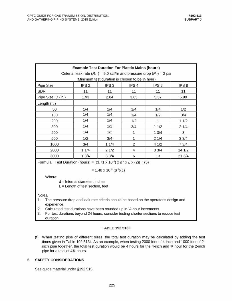
GPTC GUIDE FOR GAS TRANSMISSION, DISTRIBUTION, §192.513 AND GATHERING PIPING SYSTEMS: 2015 Edition SUBPART J
225
Example Test Duration For Plastic Mains (hours) Criteria: leak rate (RL ) = 5.0 scf/hr and pressure drop (Pd) = 2 psi
(Minimum test duration is chosen to be ¼ hour) Pipe Size IPS 2 IPS 3 IPS 4 IPS 6 IPS 8 SDR 11 11 11 11 11 Pipe Size ID (in.) 1.93 2.84 3.65 5.37 6.99 Length (ft.)
50 1/4 1/4 1/4 1/4 1/2 100 1/4 1/4 1/4 1/2 3/4 200 1/4 1/4 1/2 1 1 1/2 300 1/4 1/2 3/4 1 1/2 2 1/4 400 1/4 1/2 1 1 3/4 3 500 1/2 3/4 1 2 1/4 3 3/4 1000 3/4 1 1/4 2 4 1/2 7 3/4 2000 1 1/4 2 1/2 4 8 3/4 14 1/2 3000 1 3/4 3 3/4 6 13 21 3/4
Formula: Test Duration (hours) = [(3.71 x 10⁻⁴) x d 2 x L x (2)] ÷ (5)
= 1.48 x 10⁻⁴ (d 2)(L)
Where: d = Internal diameter, inches L = Length of test section, feet Notes: 1. The pressure drop and leak rate criteria should be based on the operator’s design and experience. 2. Calculated test durations have been rounded up in ¼-hour increments. 3. For test durations beyond 24 hours, consider testing shorter sections to reduce test duration.
TABLE 192.513ii
(f) When testing pipe of different sizes, the total test duration may be calculated by adding the test
times given in Table 192.513ii. As an example, when testing 2000 feet of 4-inch and 1000 feet of 2-inch pipe together, the total test duration would be 4 hours for the 4-inch and ¾ hour for the 2-inch pipe for a total of 4¾ hours.
5 SAFETY CONSIDERATIONS See guide material under §192.515.
GPTC GUIDE FOR GAS TRANSMISSION, DISTRIBUTION, §192.513 AND GATHERING PIPING SYSTEMS: 2015 Edition SUBPART J
226
6 OTHER See 2 and 4 of the guide material under §192.505; guide material under §§192.515 and 192.517; and
Guide Material Appendices G-192-9, G-192-9A, and G-192-10.
§192.515 Environmental protection and safety requirements.
[Effective Date: 11/12/70]
(a) In conducting tests under this subpart, each operator shall insure that every reasonable precaution is taken to protect its employees and the general public during the testing. Whenever the hoop stress of the segment of the pipeline being tested will exceed 50 percent of SMYS, the operator shall take all practicable steps to keep persons not working on the testing operation outside of the testing area until the pressure is reduced to or below the proposed maximum allowable operating pressure. (b) The operator shall insure that the test medium is disposed of in a manner that will minimize damage to the environment.
GUIDE MATERIAL 1 GENERAL See 3.1 and 4.1 of the guide material under §192.505. 2 SAFETY CONSIDERATIONS 2.1 General. The following are other factors to be considered in the interest of safety. (a) Locating personnel operating testing equipment at a safe distance from the pipeline facilities under
test. (b) Visually inspecting temporary piping, closures, and other equipment used in connection with the
test, both prior to the application of the test pressure and at appropriate intervals during the test, to ensure soundness.
(c) Providing for supports or anchors, as required, to prevent excessive stress levels in the test piping and the piping under test.
(d) Locating blowdown devices in a manner that will divert the gas and the test medium away from electrical conductors.
(e) Filling and purging the facilities in a manner consistent with good purging principles, taking into consideration the following.
(1) Compliance with the requirements in §192.629. (2) Minimizing entrapment of air or gas in the pipeline segment to be subjected to hydrostatic test
by inserting a sphere or other suitable device ahead of the test medium while filling, or by installing vents at high spots.
(3) Wind direction and velocity. (4) Prevention of accidental ignition. See §192.751. (f) Communications between the supervisor in charge and the line surveillance teams, pressure control
and monitor stations, blowdown points and other stations or personnel responsible for various aspects of the work.
(g) Ready availability of fire extinguishers, breathing apparatus, safety harnesses, ear protection

GPTC GUIDE FOR GAS TRANSMISSION, DISTRIBUTION, §192.515 AND GATHERING PIPING SYSTEMS: 2015 Edition SUBPART J
227
devices, combustible gas detectors, oxygen deficiency indicators and other such equipment in the work area.
(h) Distribution of a written test procedure (including the applicable portions of Guide Material Appendix G-192-12) to employees or contractor personnel or both. The procedure should be reviewed with all persons involved in conducting the test prior to commencing any work and should include actions to be taken in the event of a test failure.
2.2 Tests in excess of 50 percent SMYS. When the test will result in hoop stresses in excess of 50% SMYS, particularly in uprating facilities, each
operator should consider the following precautionary measures to ensure that the test area is kept clear of persons not directly engaged in the testing operation.
(a) Placing caution signs or barriers along the pipeline route wherever deemed appropriate, such as at roads and public corridors. These should be supplemented by security patrols or guards or both in residential areas, industrial areas and at river crossings.
(b) Aerial surveillance of the pipeline route, when practical, to monitor activity in the test area when testing with natural gas, inert gas or air.
(c) Notifying parties located in the general vicinity of the pipeline to avoid the test area during the period of the test.
(d) Notifying law enforcement agencies, fire departments, state and county highway departments, railroad and utility companies with facilities in the test area and, as applicable, airport operators regarding the scope and period of the test.
(e) When the test is being conducted in high exposure areas, consideration should be given to the following.
(1) Scheduling the test at a time to minimize public exposure. (2) Limiting the length of the test section to minimize potential hazards. 2.3 Tests in excess of 90 percent SMYS. When the test pressure will produce a hoop stress in excess of 90% of SMYS, the following additional
precautions may be considered to minimize the risk to occupants of buildings in close proximity to the pipeline.
(a) Using pre-tested pipe. (b) Pre-testing the segment. (c) Using energy absorbing devices (e.g., sandbag barriers, backfill, piling, and walls). 3 HAZARDS ASSOCIATED WITH FILLING AND DEWATERING PIPELINES FOR HYDROSTATIC
TESTING (a) During the filling and dewatering processes, significant and sudden variations in pressure may occur
within the pipeline and the temporary filling and dewatering piping. These variations can be caused by changes in velocity of the pig passing through bends in the pipeline or of the pig and water due to changes in pipeline elevation. Compressed air escaping around a pig can also create a source for stored energy within the pipeline. The release of this stored energy, as well as surges transferred from the pipeline to the temporary filling and dewatering piping, can result in pipe movement.
(b) When conducting a hydrostatic test, the following should be considered when filling and dewatering pipelines.
(1) Prepare a detailed test plan that includes the required equipment, test duration, and test pressure.
(2) Conduct training for the individuals involved with the test that includes a review of the test and dewatering plan, instructions on the filling/dewatering system installation and techniques, and proper coupling and anchoring methods.
(3) Perform an engineering analysis of the existing and temporary piping systems to identify the forces that could adversely affect the integrity of the pipeline, the integrity of temporary fill piping, or the integrity and stability of the drainage components, such as excessive or variable pressures caused by a stuck pig or leaks. An engineering analysis may consist of the following.

GPTC GUIDE FOR GAS TRANSMISSION, DISTRIBUTION, §192.515 AND GATHERING PIPING SYSTEMS: 2015 Edition SUBPART J
228
(i) Designing the temporary piping system within the parameters of the hydrostatic pressure test. Consider factors such as the diameter and pressure rating of the temporary piping system (including couplings and fittings), the joining method, and the piping geometry.
(ii) Accounting for hydrostatic head pressure caused by changes in elevation. (iii) Considering pressure variations or thrust due to changes in direction at bends, elbows,
and dead-ends. (iv) Determining the proper joining method for the temporary piping system. (4) Develop installation techniques that address forces expected during the filling, testing, and
dewatering operations. Those techniques would include effective anchoring systems that prevent pipe movement, separation, or whipping. Piping components (e.g., couplings, flanges, valves) should be free of damage and installed in accordance with manufacturer’s instructions.
(5) Inspect temporary pipe, couplings, and fittings to ensure they are in good condition and rated for the pressure and temperature conditions specified for the test.
(6) Ensure that anchoring and support systems are installed in accordance with the plan. (7) Control access to the area around the test site by establishing a limited-access zone to keep out
persons not involved with the test. (c) For additional background information on this subject, see OPS Advisory Bulletin ADB-04-01 (69 FR
58225, Sept. 29, 2004; reference Guide Material Appendix G-192-1, Section 2). 4 ENVIRONMENTAL CONSIDERATIONS Each operator, in fulfilling the local, state, and federal environmental regulations with respect to the
disposal of the test medium, should, among other things, give consideration to the following. (a) Selecting water from satisfactory sources. (b) Mitigating erosion and flooding of the area where the water is being discharged. (c) Using filters, impoundment facilities or other appropriate methods to ensure that the atmosphere
and the surface waters are not unnecessarily contaminated by the products being discharged. (d) Using silencers, during the blowdown operation, where sound might be generated which is
objectionable to area residents. (e) Scheduling and locating the blowdown to minimize public objection to the noise generated.
§192.517 Records.
[Effective Date: 10/15/03]
(a) Each operator shall make, and retain for the useful life of the pipeline, a record of each test performed under §§192.505 and 192.507. The record must contain at least the following information: (1) The operator's name, the name of the operator's employee responsible for making the test, and the name of any test company used. (2) Test medium used. (3) Test pressure. (4) Test duration. (5) Pressure recording charts, or other record of pressure readings. (6) Elevation variations, whenever significant for the particular test. (7) Leaks and failures noted and their disposition. (b) Each operator must maintain a record of each test required by §§192.509, 192.511, and 192.513 for at least 5 years. [Amdt. 192-93, 68 FR 53895, Sept. 15, 2003]

GPTC GUIDE FOR GAS TRANSMISSION, DISTRIBUTION, §192.517 AND GATHERING PIPING SYSTEMS: 2015 Edition SUBPART J
Addendum 2, July 2015 229
GUIDE MATERIAL (a) In addition to the requirements of §192.517(a), records of a pressure test should include the following. (1) Start and completion times of the test. (2) Name of the person responsible for performing the test and the person who approved the test, if
different. (3) A detailed description of the segment of pipeline and associated components that were tested,
which should include: (i) For station piping, a diagram of the station that identifies the location of the tested segment; (ii) For a pipeline, the segment length using mile markers, stationing, or other location description; (iii) For pipeline components, the type, size, locations, and pressure ratings; and (iv) For all tested pipe, the following. (A) Outside diameter. (B) Wall thickness. (C) Pipe grade or designation. (D) Pipe material. (E) Joint types. (F) Seam type. (b) Records of a successful hydrostatic pressure test might include the following in addition to that listed
under (a) above. (1) Minimum and maximum elevation values, including the calculated test pressure, measured test
pressure, or both at the control point as well as the highest and lowest points. (2) Temperatures recorded throughout the duration of the test: (i) Ambient air. (ii) Underground (restrained) piping. (iii) Aboveground (unrestrained) piping. (3) Liquid volume injected, withdrawn, or both, during the test. (4) Pressure versus volume plot. Note: To confirm that the test did not reveal any leaks or yield the pipe, taking into consideration the
thermal effects on unrestrained piping throughout the duration of the test. (c) For pre-November 12, 1970 pipelines, operators might not have pressure test records that meet all of
the current requirements under §192.517(a). In the event a pressure test was conducted prior to that date, an operator may consider several different types of records that verify a pressure test was conducted. Preferably, those records would include a date and signature of the individual who witnessed the test. Any one or combination of the following records may be considered.
(1) Test pressure records, including charts or other forms indicating pressure recordings. (2) Job-specific pressure test plan and procedure. (3) Notation of completion of pressure test requirements on as-built drawings. (4) Field notes or log books with details of testing. (5) An operator form with details of the pressure test. (6) Other documents that the operator deems appropriate per their specific standards. (d) For tests conducted under §§192.509, 192.511, or 192.513, records are required to show that the tests
have been conducted. The date, location of the test, and the test pressure applied may be sufficient documentation. Additional information may be included at the discretion of the operator.
(e) For segments of steel service line stressed to 20% or more of SMYS (§192.511(c)), records are required
to document testing in accordance with §192.507. (f) For a non-welded joint used to tie in a pipeline, the operator should have a record demonstrating that a
leak test was performed at not less than the operating pressure (see §192.503(d)).

GPTC GUIDE FOR GAS TRANSMISSION, DISTRIBUTION, §192.517 AND GATHERING PIPING SYSTEMS: 2015 Edition SUBPART J
230
BLANK

GPTC GUIDE FOR GAS TRANSMISSION, DISTRIBUTION, §192.551 AND GATHERING PIPING SYSTEMS: 2015 Edition SUBPART K
231
SUBPART K UPRATING
§192.551 Scope.
[Effective Date: 11/12/70]
This subpart prescribes minimum requirements for increasing maximum allowable operating pressures (uprating) for pipelines.
GUIDE MATERIAL
No guide material necessary.
§192.553 General requirements.
[Effective Date: 10/15/03]
(a) Pressure increases. Whenever the requirements of this subpart require that an increase in operating pressure be made in increments, the pressure must be increased gradually, at a rate that can be controlled, and in accordance with the following: (1) At the end of each incremental increase, the pressure must be held constant while the entire segment of pipeline that is affected is checked for leaks. (2) Each leak detected must be repaired before a further pressure increase is made, except that a leak determined not to be potentially hazardous need not be repaired, if it is monitored during the pressure increase and it does not become potentially hazardous. (b) Records. Each operator who uprates a segment of pipeline shall retain for the life of the segment a record of each investigation required by this subpart, of all work performed, and of each pressure test conducted, in connection with the uprating. (c) Written plan. Each operator who uprates a segment of pipeline shall establish a written procedure that will ensure that each applicable requirement of this subpart is complied with. (d) Limitation on increase in maximum allowable operating pressure. Except as provided in §192.555(c), a new maximum allowable operating pressure established under this subpart may not exceed the maximum that would be allowed under §§192.619 and 192.621 for a new segment of pipeline constructed of the same materials in the same location. However, when uprating a steel pipeline, if any variable necessary to determine the design pressure under the design formula (§192.105) is unknown, the MAOP may be increased as provided in §192.619(a)(1). [Amdt. 192-78, 61 FR 28770, June 6, 1996 with Amdt. 192-78 Correction, 61 FR 30824, June 18, 1996; Amdt. 192-93, 68 FR 53895, Sept. 15, 2003]

GPTC GUIDE FOR GAS TRANSMISSION, DISTRIBUTION, §192.553 AND GATHERING PIPING SYSTEMS: 2015 Edition SUBPART K
Addendum 6, December 2016 232
GUIDE MATERIAL 1 GENERAL CONSIDERATIONS In fulfilling the requirements of Subpart K (and any state and local requirements for uprating), it is recommended that the written plan required by §192.553(c) include, as applicable, the following. (a) The purpose of pressure increase. (b) The amount of increase and the proposed MAOP. (c) The location class(es) of the segment being uprated. (d) A review of the requirements in §§192.619, 192.621, and 192.623 to ensure that the proposed new
maximum allowable operating pressure may be adopted. (e) A review of the overpressure protection requirements in §§192.195, 192.199, and 192.201. (f) A review to ensure proper capacity, set points, and function of the devices in accordance with
§§192.739, 192.741, and 192.743. (g) A description of the facility. This can be a schematic map to clearly define the pipeline segment to
be uprated and all adjacent pipelines and mains. This map should indicate the following. (1) Construction dates. (2) Size, wall thickness, and grade of pipe. (3) Laterals, side connections and other appurtenances. (h) A review of the uprating’s effect on the operator’s integrity management program and the control
room management procedures. (i) A schedule of proposed work. The steps to be taken to accomplish the uprating should be listed. (j) The definition and assignment of responsibility to complete the various phases of a line uprating
including a check and verification procedure which will ensure that all steps have been completed in compliance with the federal standards before higher pressure is introduced into the system to be uprated.
(k) The sequence of steps necessary to isolate adjacent piping from the system to be uprated. Remaining connections to adjacent piping, which will operate at a lower pressure, should be at points where pressure reducing equipment has been installed in compliance with §§192.195 and 192.201.
(l) A determination that adequate pressure can be maintained in adjacent systems when the section to be uprated is isolated. If additional interconnections with a higher operating pressure system are required to maintain the lower pressure system, these connections should conform to the federal standards.
(m) A procedure for the instruction of all personnel involved in the uprating procedure to ensure familiarity with the plan.
(n) The notification of all affected customers sufficiently in advance to ensure maximum accessibility of premises during the uprating operation.
(o) The alterations to pressure regulation and pressure relief facilities necessary to meet the requirements of §§192.195 and 192.201.
(p) The precautions to be taken to protect employees and the general public during the uprating operation.
(q) Provision for monitoring pressure in adjacent facilities during uprating. This should be done to ensure that there are no connections, from the higher pressure system to a lower pressure system, that do not have pressure reducing equipment conforming to the federal standards.
(r) Provision for a final leak survey to confirm the integrity of the facility after uprating is completed. 2 DISTRIBUTION SYSTEMS
The following additional items, as applicable, are recommended for the written plans of uprating projects in distribution systems.
(a) A list of locations where sectionalizing valves are to be installed to meet the requirements of §192.181.
(b) A list of service lines on the main segments to be uprated.

GPTC GUIDE FOR GAS TRANSMISSION, DISTRIBUTION, §192.553 AND GATHERING PIPING SYSTEMS: 2015 Edition SUBPART K
233
(c) Provision for checking in the field the source of gas supply for all properties: (1) Within the boundaries of the affected area. (2) Adjoining the boundaries of the affected area. This is particularly significant for low-pressure
service lines that have no service regulators. (d) A list of those inactive lines, connected to the segment, which will be abandoned in accordance with
§192.727. (e) A list of service-line valves to be installed to meet the requirements of §§192.363 and 192.365 (if
applicable).
§192.555 Uprating to a pressure that will produce a hoop stress
of 30 percent or more of SMYS in steel pipelines. [Effective Date: 11/12/70]
(a) Unless the requirements of this section have been met, no person may subject any segment of a steel pipeline to an operating pressure that will produce a hoop stress of 30 percent or more of SMYS and that is above the established maximum allowable operating pressure. (b) Before increasing operating pressure above the previously established maximum allowable operating pressure the operator shall — (1) Review the design, operating, and maintenance history and previous testing of the segment of pipeline and determine whether the proposed increase is safe and consistent with the requirements of this part; and (2) Make any repairs, replacements, or alterations in the segment of pipeline that are necessary for safe operation at the increased pressure. (c) After complying with paragraph (b) of this section, an operator may increase the maximum allowable operating pressure of a segment of pipeline constructed before September 12, 1970, to the highest pressure that is permitted under §192.619, using as test pressure the highest pressure to which the segment of pipeline was previously subjected (either in a strength test or in actual operation). (d) After complying with paragraph (b) of this section, an operator that does not qualify under paragraph (c) of this section may increase the previously established maximum allowable operating pressure if at least one of the following requirements is met: (1) The segment of pipeline is successfully tested in accordance with the requirements of this part for a new line of the same material in the same location. (2) An increased maximum allowable operating pressure may be established for a segment of pipeline in a Class 1 location if the line has not previously been tested, and if — (i) It is impractical to test it in accordance with the requirements of this part; (ii) The new maximum operating pressure does not exceed 80 percent of that allowed for a new line of the same design in the same location; and (iii) The operator determines that the new maximum allowable operating pressure is consistent with the condition of the segment of pipeline and the design requirements of this part. (e) Where a segment of pipeline is uprated in accordance with paragraph (c) or (d) (2) of this section, the increase in pressure must be made in increments that are equal to — (1) 10 percent of the pressure before the uprating; or (2) 25 percent of the total pressure increase, whichever produces the fewer number of increments.

GPTC GUIDE FOR GAS TRANSMISSION, DISTRIBUTION, §192.555 AND GATHERING PIPING SYSTEMS: 2015 Edition SUBPART K
234
GUIDE MATERIAL 1 REVIEW PRIOR TO INCREASING OPERATING PRESSURE (§192.555(b)(1)) The following list contains items that an operator should consider when performing the required review. 1.1 Design review. (a) Present class location. (b) Adequacy of the original design, and of any change made to the original design during or
subsequent to the original installation, for service at the proposed maximum allowable operating pressure. Particular attention should be paid to the following.
(1) Material identification as shown on operator records. (2) Use of mill or other material analysis or inspection reports, or field inspections to resolve
discrepancies or determine unknown values. (3) Pressure/temperature ratings of components, especially rated pressure at the limiting
temperature of valves, regulators, etc. (4) Longitudinal joint factor (E) of pipe. See §192.113. (5) End closures. (6) Flexibility of piping arrangements. For pipe which design pressure cannot be calculated because one or more of the variables for
determining the design pressure in §192.105 is unknown, a value may be determined in accordance with §192.619(a)(1).
(c) Present right-of-way conditions such as the following. (1) Buried pipelines that have become exposed. (2) Pipeline segments crossing or with in the right-of-way of public roads. (3) Crossings exposed to heavy vehicular traffic. (4) Pipeline segments subject to additional mechanical stress due to support settlement or other
factors. (d) Adequacy of mill tests on pipe that has not been tested after installation to at least 118% of the
proposed maximum allowable operating pressure. (e) Characteristics, at the proposed maximum allowable operating pressure, of existing regulators, flow
controllers and other instruments. (f) Need, for operation at the proposed maximum allowable operating pressure, for additional flow
control, pressure limiting, or shut-off components. (g) Adequacy of connected facilities. 1.2 Operating history review. (a) Date of original construction (before or after September 12, 1970). (b) Operating pressures and temperatures experienced by the pipeline segment. (c) For segments of pipeline constructed before September 12, 1970, records of an operating pressure
appropriate for use as a test pressure as permitted under §192.555(c). (d) Leakage history records. (e) Corrosion records. (f) Cathodic protection (CP). (1) Date installed. (2) Level maintained. (3) Substantial changes in CP requirements. (g) Unusual operating conditions. (h) Failure and emergency reports including the possibility of recurrence because of the increased
pressure.

GPTC GUIDE FOR GAS TRANSMISSION, DISTRIBUTION, §192.557 AND GATHERING PIPING SYSTEMS: 2015 Edition SUBPART K
Addendum 6, December 2016 237
(c) An analysis of stresses imposed on cast iron and ductile-iron pipe wherein operators commonly use the design criteria addressed in §192.557(d).
(d) An analysis of the original design and construction of the pipeline and the ability to safely contain the higher pressure. Consideration should be given to the possibility that the increased pressure may cause leaks.
(e) A review of leakage, corrosion, operating pressure, and maintenance history to ascertain the present condition of facilities.
(f) An analysis of the effect of the ultimate separation and uprating on adjoining facilities. (g) A review of General Considerations in 1 of the guide material under §192.553. 1.2 Additional consideration. (a) An analysis should be made to confirm that the proposed MAOP is in accordance with the
requirements as set forth in §192.553(d). (b) For cast iron pipe, see Guide Material Appendix G-192-18. 2 WORK PRELIMINARY TO UPRATING 2.1 Leak survey. A leak survey may be required by §192.557(b)(2). Types of leakage surveys are described in Guide
Material Appendix G-192-11 (Natural Gas) and Guide Material Appendix G-192-11A (Petroleum Gas). 2.2 Changes to the system. Repairs, replacements, or other alterations necessary for the safe operation of both the system to be
uprated and the existing system should include the following. (a) Installation of anchors or joint reinforcement as required in §192.557(b)(4). (b) Renewal of gas service lines where warranted. (c) Installation of service line shut-off valves where required and in accordance with §§192.363 and
192.365. (d) Installation of service regulators where required and in accordance with §§192.197, 192.353,
192.355, and 192.357. (e) Consideration of the adequacy of existing service regulators and their characteristics with present
orifice sizing at the proposed pressure levels. 2.3 Monitoring. Provision should be made for monitoring field pressures prior to and during uprating to ensure the
integrity of both the system to be uprated and the adjacent systems that might be affected by the uprating.
2.4 Interface. The necessary field work should be performed to provide positive control to avoid overpressuring the
sections of the systems that are not being uprated. Control procedures may involve actual physical separation of sections, installation of regulator equipment that is properly operated and set to control at the proper pressure, or other effective means of separation.
2.5 Customer notification. Customers should be notified of planned interruptions of gas service. 3 INCREASING PRESSURE 3.1 Communications. Lines of communication should be established between all control points. 3.2 Isolation. The system should be isolated from all lower pressure systems.
GPTC GUIDE FOR GAS TRANSMISSION, DISTRIBUTION, §192.557 AND GATHERING PIPING SYSTEMS: 2015 Edition SUBPART K
238
3.3 Pressure regulation. The valve to each service regulator should be closed or the operation of each service regulator should
be monitored as the pressure in the main is increased. 3.4 Leak check.
See §192.553(a)(1). 3.5 Leak repairs.
See §192.553(a)(2). 3.6 Monitoring. The pressure in adjacent facilities should be monitored during the uprating procedure to establish: (a) That no connection is acting as a source of unregulated gas from the higher pressure segment to
the lower pressure system; and (b) The adequacy of the remaining lower pressure system at points of separation and other locations. 3.7 Final leak survey. After the uprating is completed, a final leak survey should be made to confirm the integrity of the
facilities. Necessary leak repairs should be made. 4 RECORDS The records of investigations, the work, and the testing should be forwarded to the proper department
for retention for the life of the facility.

GPTC GUIDE FOR GAS TRANSMISSION, DISTRIBUTION, §192.612 AND GATHERING PIPING SYSTEMS: 2015 Edition SUBPART L
253
3 REPORTING (§192.612(c)(1))
In addition to the reporting requirements of §192.612(c)(1), an operator should also consider including the following.
(a) Latitude and longitude of the pipeline end points. (b) Offshore area name. (c) Offshore block number. (d) Name of water body. (e) Name of parish or county. (f) Other pertinent information. 4 REMEDIAL ACTION
If an operator is unable to meet the deadline for remediation, the required notification to OPS should be in writing.
§192.613 Continuing surveillance.
[Effective Date: 11/12/70]
(a) Each operator shall have a procedure for continuing surveillance of its facilities to determine and take appropriate action concerning changes in class location, failures, leakage history, corrosion, substantial changes in cathodic protection requirements, and other unusual operating and maintenance conditions. (b) If a segment of pipeline is determined to be in unsatisfactory condition but no immediate hazard exists, the operator shall initiate a program to recondition or phase out the segment involved, or, if the segment cannot be reconditioned or phased out, reduce the maximum allowable operating pressure in accordance with §192.619(a) and (b).
GUIDE MATERIAL 1 GENERAL Continuing surveillance should be conducted to identify any pipeline facilities experiencing abnormal or
unusual operating and maintenance conditions. This may be accomplished by the following. (a) Periodic visual inspection of facilities to identify items such as the following. (1) Changes of population densities. (2) Effects of exposure or movement of pipeline facilities. (3) Changes in topography that may have an effect on pipeline facilities. (4) Potential for, or evidence of, tampering, vandalism, or damage. (5) Effects of encroachments on pipeline facilities. (6) Potential for gas migration through air intakes into buildings from vaults and pits. (7) Specific circumstances relating to patrolling and leakage. See guide material under §§192.705,
192.706, 192.721, and 192.723. (8) Potential for, or evidence of, soil or water accumulation in vaults or pits. (9) Potential for, or evidence of, excavation activity. If evidence of an excavation is found near a
transmission pipeline covered segment, the location must be examined in accordance with §192.935(b)(1)(iv).
(10) Potential for, or evidence of, mining activity. See Guide Material Appendix G-192-13. (11) Potential for, or evidence of, flooding. See 6 below.

GPTC GUIDE FOR GAS TRANSMISSION, DISTRIBUTION, §192.613 AND GATHERING PIPING SYSTEMS: 2015 Edition SUBPART L
Addendum 6, December 2016 254
(b) Periodic review and analysis of records, such as the following. (1) Patrols. (2) Leak surveys. (3) Valve inspections. (4) Vault inspections. (5) Pressure regulating, relieving, and limiting equipment inspections. (6) Corrosion control inspections. (7) Facility failure investigations.
Anomalies discovered should be evaluated, and those determined to present potential safety concerns should be scheduled for remediation and communicated to appropriate integrity management personnel.
2 CAST IRON PIPELINES For cast iron pipelines, see Guide Material Appendix G-192-18. 3 PE PIPELINES (a) Some PE materials manufactured before 1982 have a lower resistance to the effects of induced
stresses and are subject to brittle-like cracking under certain in-service conditions (e.g., rock impingement, squeeze-offs, severe bending moments). Brittle-like cracking is characterized by a part-through crack initiating in the pipe wall followed by slow crack growth causing failure. These failures result in a tight slit-like opening and a gas leak. This older generation of PE may have leak-free performance for a number of years before brittle-like cracks occur. An increase in the occurrence of leaks is typically the first indication of a brittle-like cracking problem.
(b) PE materials that are most known for this failure mode include the following. (1) Century Utility Products, Inc. products. (2) Low-ductile inner wall PE 2306 "Aldyl A" pipe manufactured by DuPont Company during 1970
through 1972, generally NPS 1¼ to NPS 4. To determine if the "Aldyl A" pipe has low-ductile inner wall, see 3(f) below.
(3) PE gas pipe designated PE 3306. (4) DuPont PE tapping tees with DuPont Delrin® polyacetal (homopolymer) inserts (see 3(g)
below). (5) Plexco PE service tees with Celanese Celcon® polyacetal (copolymer) caps (see 3(h) below). (c) Conditions that may cause these types of materials to fail prematurely include the following. (1) Inadequate support and backfill during installation. (2) Tree root or rock impingement. (3) Shear and bending stresses due to differential settlement resulting from factors such as: (i) Excavation in close proximity to PE piping. (ii) Directional drilling in close proximity to PE piping. (iii) Frost heave. (4) Bending stresses due to pipe installations with bends exceeding recommended practices. (5) Stresses where the pipe has been squeezed off. (d) Each operator that has these older PE pipelines should consider the following practices. (1) Review system records to determine if any known susceptible materials have been installed in
the system. (2) Perform more frequent inspection and leak surveys on systems that have exhibited brittle-like
cracking failures of known susceptible materials. (3) Collect failure samples of PE piping exhibiting brittle-like cracking. (4) Record the print line from any piping that has been involved in a failure. The print line
information can be used to identify the resin, manufacturer, and year of manufacture for plastic piping.

GPTC GUIDE FOR GAS TRANSMISSION, DISTRIBUTION, §192.613 AND GATHERING PIPING SYSTEMS: 2015 Edition SUBPART L
Addendum 6, December 2016 259
Additional guidance on mitigation methods may be found in ASME STP-PT-011, "Integrity Management of Stress Corrosion Cracking in Gas Pipeline High Consequence Areas," which documents a joint industry project.
4.2 References. (a) ASME B31.8S, Appendix A3 and Table 4 (see §192.7). (b) ASME STP-PT-011, "Integrity Management of Stress Corrosion Cracking in Gas Pipeline High
Consequence Areas." (c) NACE Publication 35103, "External Stress Corrosion Cracking of Underground Pipelines." (d) NACE SP0204, "Stress Corrosion Cracking (SCC) Direct Assessment Methodology." (e) National Energy Board (Canada), Report of the Inquiry MH-2-95, "Stress Corrosion Cracking on
Canadian Oil and Gas Pipelines," December 1996. (f) OPS Advisory Bulletin ADB-03-05 (68 FR 58166, Oct. 8, 2003; see Guide Material Appendix G-192-
1, Section 2). (g) OPS Technical Task Order Number 8, "Stress Corrosion Cracking Study," Michael Baker, Jr., Inc.,
January 2005. (h) PRCI L52047, "Pipeline Repair Manual." (i) "SCC Detection and Mitigation Based on In-Line Inspection Tools," W. Kresic and S. Ironside, Paper
# IPC2004-0375 presented at ASME International Pipeline Conference, Calgary, October 2004. 5 THREADED JOINTS
Operators that have threaded joints in underground gas systems may want to determine if increased surveillance is warranted. Factors that could be considered include wall thickness, leak history, susceptibility to corrosion, settlement, frost-induced movement, and third-party damage.
6 SEVERE FLOODING Severe flooding can adversely affect the safe operation of a pipeline. Operators should consider the
following actions in areas prone to, or previously affected by, flooding. (a) Identify pipeline facilities that are in the flood plain, such as overlaying 100-year flood elevations on
GIS pipeline maps. (b) For buried pipelines, consider terrain and vegetation conditions that can cause severe scouring of
the watercourse. Such conditions could include burned areas subject to soil erosion and long-term buildup of debris and vegetation along the watercourse.
(c) For aerial or aboveground pipeline crossings, consider the potential for the following. (1) Scouring of deadman anchors and tower foundations on cable-supported pipelines and traffic
or pedestrian bridges. (2) Floating debris impacting the pipeline and its supports beneath or on the upstream side of
traffic or pedestrian bridges. (d) Extend regulator vents and relief stacks above the level of anticipated flooding, as appropriate. (e) Determine if facilities that are normally above ground (e.g., valves, regulators, relief devices) could
become submerged and then have a potential for being struck by vessels or debris, and consider protecting or relocating such facilities.
(f) For additional information, see OPS Advisory Bulletin ADB-2016-01 (81 FR 2943, Jan 19, 2016; see Guide Material Appendix G-192-1, Section 2).
7 SERVICE LINES UNDER BUILDINGS Buried and uncased service lines discovered under buildings should be moved to locations no longer
beneath the building or reinstalled under the building in accordance with the requirements of §192.361. In instances involving mobile homes, it may be possible to have the home relocated away from the service line. See guide material under §192.361.

GPTC GUIDE FOR GAS TRANSMISSION, DISTRIBUTION, §192.613 AND GATHERING PIPING SYSTEMS: 2015 Edition SUBPART L
Addendum 2, July 2015 260
8 INTEGRITY MANAGEMENT CONSIDERATIONS Conditions or information discovered that could affect the integrity of a pipeline should be reported to the
appropriate integrity management and operating personnel.
§192.614 Damage prevention program.
[Effective Date: 07/20/98]
(a) Except as provided in paragraphs (d) and (e) of this section, each operator of a buried pipeline shall carry out, in accordance with this section, a written program to prevent damage to that pipeline from excavation activities. For the purpose of this section, the term "excavation activities" includes excavation, blasting, boring, tunneling, backfilling, the removal of aboveground structures by either explosive or mechanical means, and other earthmoving operations. (b) An operator may comply with any of the requirements of paragraph (c) of this section through participation in a public service program, such as a one-call system, but such participation does not relieve the operator of responsibility for compliance with this section. However, an operator must perform the duties of paragraph (c)(3) of this section through participation in a one-call system, if that one-call system is a qualified one-call system. In areas that are covered by more than one qualified one-call system, an operator need only join one of the qualified one-call systems if there is a central telephone number for excavators to call for excavation activities, or if the one-call systems in those areas communicate with one another. An operator’s pipeline system must be covered by a qualified one-call system where there is one in place. For the purpose of this section, a one-call system is considered a "qualified one-call system" if it meets the requirements of section (b)(1) or (b)(2) of this section. (1) The state has adopted a one-call damage prevention program under §198.37 of this chapter; or (2) The one-call system: (i) Is operated in accordance with §198.39 of this chapter; (ii) Provides a pipeline operator an opportunity similar to a voluntary participant to have a part in management responsibilities; and (iii) Assesses a participating pipeline operator a fee that is proportionate to the costs of the one-call system’s coverage of the operator’s pipeline. (c) The damage prevention program required by paragraph (a) of this section must, at a minimum: (1) Include the identity, on a current basis, of persons who normally engage in excavation activities in the area in which the pipeline is located. (2) Provides for notification of the public in the vicinity of the pipeline and actual notification of the persons identified in paragraph (c)(1) of this section of the following as often as needed to make them aware of the damage prevention program: (i) The program's existence and purpose; and (ii) How to learn the location of underground pipelines before excavation activities are begun. (3) Provide a means of receiving and recording notification of planned excavation activities. (4) If the operator has buried pipelines in the area of excavation activity, provide for actual notification of persons who give notice of their intent to excavate of the type of temporary marking to be provided and how to identify the markings. (5) Provide for temporary marking of buried pipelines in the area of excavation activity before, as far as practical, the activity begins. (6) Provide as follows for inspection of pipelines that an operator has reason to believe could be damaged by excavation activities: (i) The inspection must be done as frequently as necessary during and after the activities to verify the integrity of the pipeline; and

GPTC GUIDE FOR GAS TRANSMISSION, DISTRIBUTION, §192.616 AND GATHERING PIPING SYSTEMS: 2015 Edition SUBPART L
Addendum 6, December 2016 281
priority than protection of property. (e) Damage prevention. See 2.5 of the guide material under §192.614. 2.4 Additional information. Distribution system operators may choose to include additional messages for recognizing and reporting
types of hazards or potential hazards not addressed by API RP 1162, such as the following. (a) Heavy snow accumulation on meter set assemblies. (b) Snow or ice falling or being shoveled from roofs onto gas facilities. (c) Ice buildup on regulators or regulator vents. (d) Carbon monoxide hazards from snow and ice buildup around combustion air and exhaust vents for
gas appliances. (e) Flooding that might affect gas facilities. 2.5 Message delivery methods. Guidance is provided in API RP 1162, Section 5 for several delivery methods and tools available for
communicating with the stakeholder audiences. See 2.4 of the guide material under §192.614 for additional information regarding delivery methods for excavators and the affected public. However, the operator is required by §192.616(c) to justify in its program or procedural manual if it does not follow the general program recommendations of API RP 1162 regarding message delivery methods.
3 LANGUAGE The following may provide indications of languages in addition to English to consider when conducting
public education programs. (a) Languages prescribed by state or local governments. (b) Commercial non-English radio, television, and print media. (c) U.S. Census data. 4 REFERENCES (a) Information regarding public education programs, such as FAQs and Workshops, is available at
primis.phmsa.dot.gov/comm/PublicEducation.htm. (b) OPS Advisory Bulletins (see Guide Material Appendix G-192-1, Section 2) as follows. (1) ADB-93-01 (58 FR 7034, Feb. 3, 1993). (2) ADB-97-01 (Issued in Kansas City, MO on Jan.24, 1997). (3) ADB-08-03 (73 FR 12796, Mar. 10, 2008). (4) ADB-11-02 (76 FR 7238, Feb. 9, 2011).
§192.617 Investigation of failures.
[Effective Date: 11/12/70]
Each operator shall establish procedures for analyzing accidents and failures, including the selection of samples of the failed facility or equipment for laboratory examination, where appropriate, for the purpose of determining the causes of the failure and minimizing the possibility of a recurrence.

GPTC GUIDE FOR GAS TRANSMISSION, DISTRIBUTION, §192.617 AND GATHERING PIPING SYSTEMS: 2015 Edition SUBPART L
282
GUIDE MATERIAL 1 GENERAL (a) Data on all failures and leaks should be compiled to support compliance with §192.613. A failure
investigation should be performed to determine the cause of the failure and minimize the possibility of a recurrence.
(b) For information on failures of PE pipe, see 3 of the guide material under §192.613. (c) For information on reporting failures of mechanical fittings, see guide material under §191.12. 2 TYPES AND NATURE OF FAILURES THAT SHOULD BE ANALYZED
Failure investigation should be conducted for incidents as defined in §191.3. An operator should also consider investigating any other failure that enables the operator to establish patterns that might be occurring on its pipeline system. For examples, see guide material under §192.613.
3 FAILURE INVESTIGATION (a) Failure investigation and subsequent analysis should determine the root cause(s) of the failure. The
investigation may be as simple as assembling an internal review group or as complex as conducting a full-scale failure investigation with laboratory analysis of a failed component. The information for completing a 30-day incident report form contained in Part 191 may constitute an adequate analysis of a reportable failure or leak. See §§191.9 and 191.15.
(b) The general process for performing root-cause analysis is as follows. (1) Assemble the review team. (2) Define the problem and gather data and documentation. (3) Identify factors that contributed to the problem (i.e., causal factors). (4) Find the root cause for each causal factor, such as people, equipment, material, process, or
outside influence. (5) Develop and assign recommendations. (6) Distribute recommendations and review the operator’s procedures. (7) Implement the recommendations. 4 RESPONSE TO FAILURE If a detailed analysis is to be made, rapid response will be necessary for preserving the integrity of
specimens and gathering information. 5 DATA COLLECTION 5.1 Incident. When a detailed analysis is to be made, a person at the scene of the incident should be designated to
coordinate the investigation. That person's responsibilities should include the following. (a) Acting as a coordinator for all field investigative personnel. (b) Maintaining a log of the personnel, equipment, and witnesses. (c) Recording in chronological order the events as they take place. (d) Ensuring that photographs are taken of the incident and surrounding areas. These photographs
may be of great value in the investigation. (e) Ensuring the notification of all appropriate governmental authorities. (f) Ensuring the preservation of evidence. 5.2 Other failures. Gather sufficient data to complete the general process for performing root-cause analysis. See 3 above.
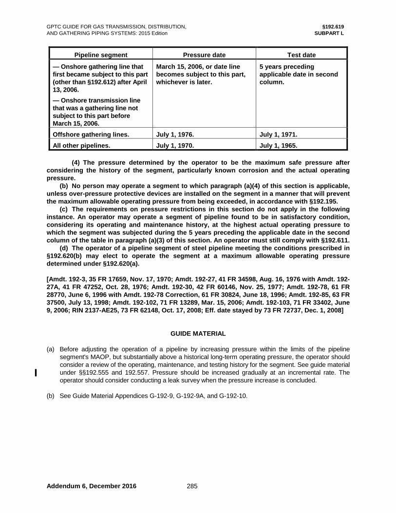
GPTC GUIDE FOR GAS TRANSMISSION, DISTRIBUTION, §192.619 AND GATHERING PIPING SYSTEMS: 2015 Edition SUBPART L
Addendum 6, December 2016 285
Pipeline segment Pressure date Test date
— Onshore gathering line that first became subject to this part (other than §192.612) after April 13, 2006. — Onshore transmission line that was a gathering line not subject to this part before March 15, 2006.
March 15, 2006, or date line becomes subject to this part, whichever is later.
5 years preceding applicable date in second column.
Offshore gathering lines. July 1, 1976. July 1, 1971. All other pipelines. July 1, 1970. July 1, 1965.
(4) The pressure determined by the operator to be the maximum safe pressure after considering the history of the segment, particularly known corrosion and the actual operating pressure. (b) No person may operate a segment to which paragraph (a)(4) of this section is applicable, unless over-pressure protective devices are installed on the segment in a manner that will prevent the maximum allowable operating pressure from being exceeded, in accordance with §192.195. (c) The requirements on pressure restrictions in this section do not apply in the following instance. An operator may operate a segment of pipeline found to be in satisfactory condition, considering its operating and maintenance history, at the highest actual operating pressure to which the segment was subjected during the 5 years preceding the applicable date in the second column of the table in paragraph (a)(3) of this section. An operator must still comply with §192.611. (d) The operator of a pipeline segment of steel pipeline meeting the conditions prescribed in §192.620(b) may elect to operate the segment at a maximum allowable operating pressure determined under §192.620(a). [Amdt. 192-3, 35 FR 17659, Nov. 17, 1970; Amdt. 192-27, 41 FR 34598, Aug. 16, 1976 with Amdt. 192-27A, 41 FR 47252, Oct. 28, 1976; Amdt. 192-30, 42 FR 60146, Nov. 25, 1977; Amdt. 192-78, 61 FR 28770, June 6, 1996 with Amdt. 192-78 Correction, 61 FR 30824, June 18, 1996; Amdt. 192-85, 63 FR 37500, July 13, 1998; Amdt. 192-102, 71 FR 13289, Mar. 15, 2006; Amdt. 192-103, 71 FR 33402, June 9, 2006; RIN 2137-AE25, 73 FR 62148, Oct. 17, 2008; Eff. date stayed by 73 FR 72737, Dec. 1, 2008]
GUIDE MATERIAL (a) Before adjusting the operation of a pipeline by increasing pressure within the limits of the pipeline
segment's MAOP, but substantially above a historical long-term operating pressure, the operator should consider a review of the operating, maintenance, and testing history for the segment. See guide material under §§192.555 and 192.557. Pressure should be increased gradually at an incremental rate. The operator should consider conducting a leak survey when the pressure increase is concluded.
(b) See Guide Material Appendices G-192-9, G-192-9A, and G-192-10.

GPTC GUIDE FOR GAS TRANSMISSION, DISTRIBUTION, §192.620 AND GATHERING PIPING SYSTEMS: 2015 Edition SUBPART L
Addendum 1, May 2015 286
§192.620 Alternative maximum allowable operating pressure for certain steel pipelines.
▌[Effective Date: 10/01/15]
(a) How does an operator calculate the alternative maximum allowable operating pressure? An operator calculates the alternative maximum allowable operating pressure by using different factors in the same formulas used for calculating maximum allowable operating pressure under §192.619(a) as follows: (1) In determining the alternative design pressure under §192.105, use a design factor determined in accordance with §192.111(b), (c), or (d) or, if none of these paragraphs apply, in accordance with the following table:
Class Location Alternative Design Factor (F)
1 2 3
0.80 0.67 0.56
(i) For facilities installed prior to December 22, 2008, for which §192.111(b), (c), or (d) applies, use the following design factors as alternatives for the factors specified in those paragraphs: §192.111(b) — 0.67 or less; 192.111(c) and (d) — 0.56 or less. (ii) [Reserved] (2) The alternative maximum allowable operating pressure is the lower of the following: (i) The design pressure of the weakest element in the pipeline segment, determined under subparts C and D of this part. (ii) The pressure obtained by dividing the pressure to which the pipeline segment was tested after construction by a factor determined in the following table:
Class Location Alternative Test Factor
1 2 3
1.25 11.50 1.50
1For Class 2 alternative maximum allowable operating pressure segments installed prior to December 22, 2008 the alternative test factor is 1.25.
(b) When may an operator use the alternative maximum allowable operating pressure calculated under paragraph (a) of this section? An operator may use an alternative maximum allowable operating pressure calculated under paragraph (a) of this section if the following conditions are met: (1) The pipeline segment is in a Class 1, 2, or 3 location; (2) The pipeline segment is constructed of steel pipe meeting the additional design requirements in §192.112; (3) A supervisory control and data acquisition system provides remote monitoring and control of the pipeline segment. The control provided must include monitoring of pressures and flows, monitoring compressor start-ups and shut-downs, and remote closure of valves per paragraph (d)(3) of this section;

GPTC GUIDE FOR GAS TRANSMISSION, DISTRIBUTION, §192.917 AND GATHERING PIPING SYSTEMS: 2015 Edition SUBPART O
Addendum 6, December 2016 409
(b) Extremely saturated soils that produce buoyant forces on pipelines. (1) River and stream crossings. (2) Lowlands, floodplains, and swamps. (3) Coastal areas prone to tidal surges from hurricanes or tropical storms. (c) Areas susceptible to frost heave. (d) Highly expansive or unstable soils (e.g., some clays or manmade soils). (e) Locations with known geologic conditions that contribute to instability (e.g., karst topography,
sinkholes, underground mining, other subsidence areas). 11.3 Fault zones. The following should be considered in evaluating an active or known fault zone. (a) Location of earthquake fault lines. (b) Previous earthquake activity. (c) Probability of future earthquake activity along fault. (d) Analyses of leaks or damage attributable to earthquake activity. 11.4 Year of installation.
Older pipeline facilities were constructed with materials and techniques that are generally not equivalent to modern facilities in terms of strength and integrity. The risk attributable to weather-related and outside force threats may be commensurate with the age of the pipeline facilities. If the installation data is not known, conservative estimates of the installation year can be used.
11.5 Pipe parameters. The following pipe parameters are factors in determining operating hoop stress. (a) Pipe grade. (b) Wall thickness. (c) Outside pipe diameter. ASME B31.8S, Appendix A9.2(g) states that the sum of all pipe stresses (e.g., longitudinal, hoop
stress, bending, overburden) is not to exceed 100% SMYS. If any of the pipe parameters are not known, conservative estimates of the missing data should be used.
11.6 Other considerations. (a) Weather-related conditions. Excessive loading from weather-related conditions that are likely to occur (see guide material
under §§192.317 and 192.615). (1) Tornadic activity or high winds. (2) Heavy snow or ice loading. (3) Lightning strikes. (4) Wild (or other) fires. (5) Flooding (see 6 of guide material under §192.613). (b) Operations and maintenance records.
Operators should review operations and maintenance records (e.g., patrolling data) to determine whether extreme loading conditions are present on their pipelines. Information may also be found in incident reports, safety-related condition reports, leakage information, abnormal operations, and other failure investigations required by §192.617.
(c) Fatigue cracking from improper loading of pipe on railcars. (d) See 15.3.2 below. 12 PLASTIC TRANSMISSION PIPELINES 12.1 General.
The following guide material is generally repetitive of Sections 6 through 11 above. The portions of those sections that are also applicable to plastic pipelines have been consolidated here for the
GPTC GUIDE FOR GAS TRANSMISSION, DISTRIBUTION, §192.917 AND GATHERING PIPING SYSTEMS: 2015 Edition SUBPART O
Addendum 3, December 2015 410
convenience of operators with plastic transmission pipelines. For additional guidance on identifying threats to plastic pipelines, see Guide Material Appendix G-192-
8, Section 4. Although that appendix is directed at distribution facilities, the threat identification process may be applied to plastic transmission pipelines.
12.2 Identification of threats to plastic pipelines.
Section 192.917 requires operators to address all potential threats to pipeline integrity. Threats for plastic pipelines may be grouped into the following categories.
(a) Time-dependent threats. Time-dependent threats are those that may grow more severe over time. Analysis based on
sound engineering practices may be used to help predict when these threats might become critical. For plastic pipelines, these threats include the following.
(1) Crack propagation. (2) Degradation due to exposure to liquid hydrocarbons. (b) Stable threats. A threat that has passed post-construction testing may be considered stable. However, stable
threats may need to be reconsidered as external factors (e.g., external loading, temperature changes, pressure changes) act upon the pipeline. Stable threats include the following.
(1) Manufacturing defects. (2) Construction defects. (3) Equipment failures. (c) Time-independent threats.
Time-independent threats are generally associated with events that may take place along the pipeline segment and can happen at any time. These threats include the following.
(1) Excavation damage. (2) Incorrect operations (includes human error). (3) Weather-related and outside force. (d) Other threats.
Section 192.917 also requires operators to analyze the pipeline for other threats that may not fit into one of the above categories. See 12.9 below.
12.3 Manufacturing threats.
This threat refers to defects of the pipe or fittings that are associated with the manufacturing process. Additional guidance for manufacturing considerations related to plastic pipelines can be found in guide material under §§192.121, 192.123 and 192.613 and OPS Advisory Bulletins (ADBs). See 15.2 below for a list of applicable ADBs.
(a) Potential manufacturing threats. (1) Identification of a manufacturing defect may be accomplished as follows. (i) By observations of pipe surfaces and fittings during normal construction, operation,
and maintenance activities. (ii) Through failure analysis, such as after incidents. (iii) During review of prior integrity assessment results. (iv) By review of Plastic Pipe Database Committee (PPDC) reports. See 15.2.2 below. (2) Some examples of pipe defects include the following. (i) Errors or upsets in material resin formulation. (ii) Wall thinning or scoring. (iii) Fiberglass reinforced plastic (FRP) delamination. (iv) Inclusions (e.g., impurities within the pipe wall). (v) Ovality (oval or egg-shaped pipe). (vi) Laminations (internal separation in pipe wall creating layers parallel to the pipe
surface). (vii) Insufficient amount of ultraviolet light stabilizers. (viii) Pipe diameter and wall thickness variations outside of tolerance. (3) Fittings (including metallic fittings) used to join plastic pipe. Defects may involve the

GPTC GUIDE FOR GAS TRANSMISSION, DISTRIBUTION, §192.917 AND GATHERING PIPING SYSTEMS: 2015 Edition SUBPART O
415
(6) Encroachment records. (i) Proximity to pipeline as indicated from patrols and surveys. (ii) Indications of digging where unreported damage could have occurred. (iii) History of excavation damage. (iv) Proposed construction drawings. (v) Damage to locating wires or facilities. (vi) Construction by others of steam or electric facilities close to the plastic pipeline. (c) Other considerations. (1) Preventive and mitigative measures that have been implemented. (2) Vehicular damage to aboveground facilities with the potential to cause damage to plastic
facilities connected below ground. (3) Inadequate cover. (4) Activities in the vicinity of the pipeline that do not require one-call notification (e.g., new
road construction, blasting, logging, deep tilling, land leveling). (5) Excavation by agencies that are exempt from one-call notification. (6) Ability to locate (see 12.4(a)(4) above). (7) Pipe installed in casing. 12.7 Incorrect operations (includes human error). (a) All facilities are subject to the threat of incorrect operations. This threat is time-independent and
may occur at any time. Potential incorrect operation threats include the following. (1) Failure to follow correct operating procedures. (2) Following incorrect, outdated, or incomplete operating procedures. (3) Unqualified person performing an unfamiliar task. (4) Use of uncalibrated or unauthorized tools. (b) Data collection.
ASME B31.8S Appendix A8 relates to metallic pipelines, but offers a useful format for data that should be collected to evaluate a plastic pipeline for incorrect operations. The following list may be applicable to plastic pipelines and should be considered by the operator.
(1) Procedure review information. The procedure review for completeness and effectiveness should include the following. (i) Procedural manual for operations, maintenance, and emergencies. (ii) Damage prevention program. (iii) Operator qualification program. (iv) Anti-drug and alcohol program. (v) Safety manual. (vi) IMP periodic evaluations. (vii) Adherence to operator procedures. (viii) Operator procedures for conducting post-incident, abnormal operations, and failure
investigations. (2) Audit information.
The results of both internal and external audits should be reviewed. Internal audits might include self audits in the following areas.
(i) Field operations. (A) Valve inspections and maintenance. (B) Leak surveys. (C) Cathodic protection of in-line metallic component or parts. (D) Patrolling. (ii) Construction activities. (iii) Office operations (e.g., documentation, processes). (iv) Mapping.
GPTC GUIDE FOR GAS TRANSMISSION, DISTRIBUTION, §192.917 AND GATHERING PIPING SYSTEMS: 2015 Edition SUBPART O
Addendum 6, December 2016 416
(3) Failures caused by incorrect operations. Failures or potential failures caused by an incorrect operation may be found in the
following reports. (i) Abnormal operations. (ii) Safety-related conditions. (iii) Root-cause analysis. (iv) Incidents. (v) Near misses. (vi) OQ disqualifications. 12.8 Weather-related and outside forces. Weather-related and outside force threats have the capability to create extreme loading conditions on
plastic pipelines (see guide material under §§192.317 and 192.615). (a) Potential weather-related and outside forces threats include the following. (1) Flooding (see 6 of the guide material under §192.613). (2) Frost heave. (3) Earthquakes. (4) Landslides. (5) Subsidence. (6) Extreme loads (e.g., equipment crossings). (b) Data collection.
ASME B31.8S, Appendix A9 generally relates to metallic pipelines, but may be useful as a format for data that should be collected to evaluate a plastic pipeline for weather and outside force damage. The following may be applicable to plastic pipelines and should be considered by the operator.
(1) Pipe joining method. Pipelines that include the following joint types may be more susceptible to leakage or
failure from the threat of weather-related and outside forces than pipelines constructed using modern joining methods.
(i) Mechanical fittings that do not have restraints to prevent pipe pull-out. (ii) Solvent cement. (iii) Adhesive. (iv) Heat fusions with a history of poor or cold fusions. (2) Topography and soil conditions.
The following topographical areas should be examined to determine if the threat associated with extreme loading conditions exists.
(i) Slopes prone to movement or other unstable areas that would induce additional stresses in a pipeline due to the movement of soil.
(ii) Extremely saturated soils that produce buoyant forces on pipelines. (A) River and stream crossings. (B) Low lands, floodplains, and swamps. (C) Coastal areas prone to tidal surges from hurricanes or tropical storms. (iii) Areas with deep frost line depths. (iv) Highly expansive or unstable soils (e.g., some clays). (v) Locations with known geologic conditions that contribute to instability (e.g., karst
topography, sinkholes, underground mining, other subsidence areas). (3) Fault zones. The following should be considered in evaluating an earthquake fault zone condition. (i) Proximity of earthquake fault zones to pipeline location. (ii) Previous earthquake activity. (iii) Probability of future earthquake activity along fault. (iv) Analyses of leaks or other damage attributable to earthquake activity.

GPTC GUIDE FOR GAS TRANSMISSION, DISTRIBUTION, Guide Material Appendix G-192-1 AND GATHERING PIPING SYSTEMS: 2015 Edition
Addendum 4, May 2016 Addendum 6, December 2016
573
2 GOVERNMENTAL DOCUMENTS (Continued)
OPS ADB-10-03 Advisory Bulletin – Girth Weld Quality Issues Due to Improper Transitioning, Misalignment, and Welding Practices of Large Diameter Line Pipe (75 FR 14243, Mar. 24, 2010)
§192.620
OPS ADB-10-08 Advisory Bulletin – Emergency Preparedness Communications (75 FR 67807, Nov. 3, 2010)
§192.615
OPS ADB-11-02 Advisory Bulletin – Dangers of Abnormal Snow and Ice Build-Up on Gas Distribution Systems (76 FR 7238, Feb. 9, 2011)
§192.616
OPS ADB-11-05 Advisory Bulletin – Potential for Damage to Pipeline Facilities Caused by the Passage of Hurricanes (76 FR 54532, Sept. 1, 2011)
§192.615
OPS ADB-12-02 Advisory Bulletin – Post-Accident Drug and Alcohol Testing (77 FR 10666, Feb. 23, 2012)
§192.605 §192.615
OPS ADB-12-03 Advisory Bulletin – Notice to Operators of Driscopipe® 8000 High Density Polyethylene Pipe of the Potential for Material Degradation (77 FR 13387, Mar. 6, 2012)
§192.917
OPS ADB-2012-07 Advisory Bulletin – Completion of Mechanical Fitting Failure Report Form, Leak Causes (77 FR 34457, June 11, 2012)
§191.12
OPS ADB-12-08 Advisory Bulletin – Inspection and Protection of Pipeline Facilities after Railway Accidents (77 FR 45417, July 31, 2012)
§192.615
OPS ADB-2012-11 Advisory Bulletin – Reporting of Exceedances of Maximum Allowable Operating Pressure (77 FR 75699, Dec. 21, 2012)
§191.23
OPS ADB-2016-01 Advisory Bulletin – Potential for Damage to Pipeline Facilities Caused by Severe Flooding (81 FR 2943, Jan. 19, 2016)
§192.613
OPS ALN-88-01 Alert Notice – Operational failures of pipelines constructed with ERW prior to 1970 (Jan 28, 1988; see document at PHMSA-OPS website)
§192.917
OPS ALN-89-01 Alert Notice – Update to ALN-88-01 (Mar 8, 1989; see document at PHMSA-OPS website)
§192.917
OPS-DOT.RSPA/DMT 10-85-1
Safety Criteria for the Operation of Gaseous Hydrogen Pipelines (Discontinued)
§192.1
OPS TTO No. 5 Technical Task Order – Low Frequency ERW and Lap Welded Longitudinal Seam Evaluation, Michael Baker Jr., Inc., et al
§192.917
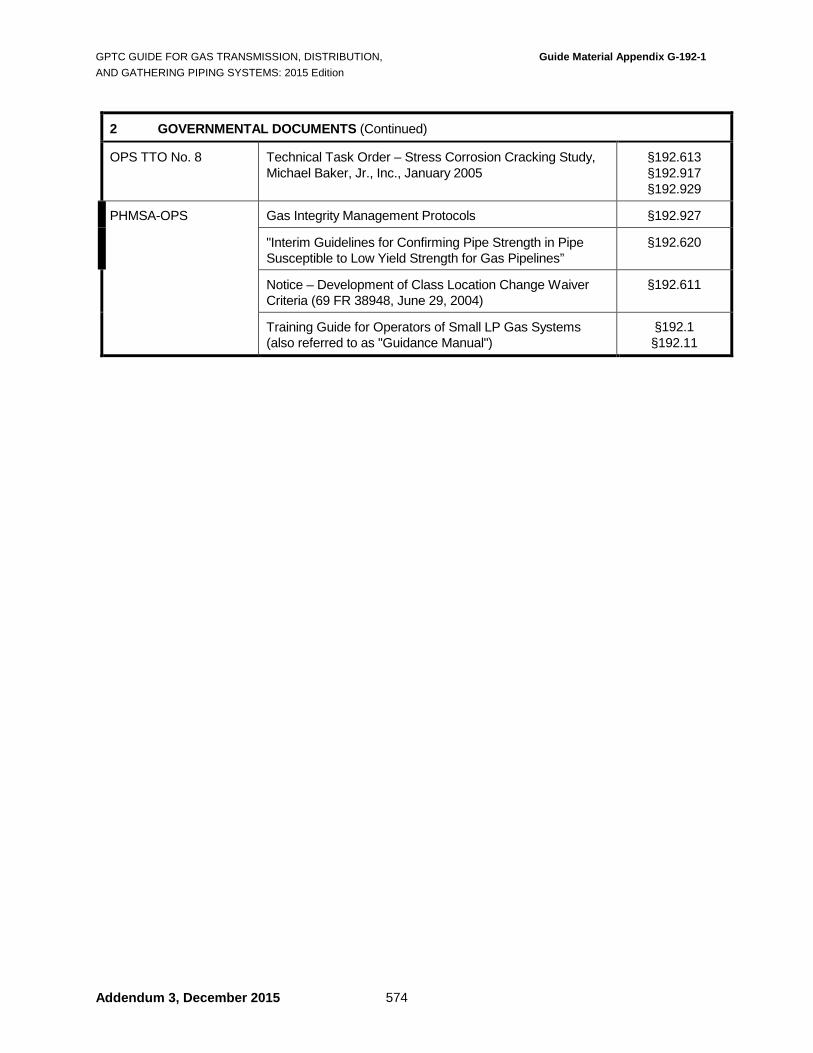
GPTC GUIDE FOR GAS TRANSMISSION, DISTRIBUTION, Guide Material Appendix G-192-1 AND GATHERING PIPING SYSTEMS: 2015 Edition
Addendum 3, December 2015 574
2 GOVERNMENTAL DOCUMENTS (Continued)
OPS TTO No. 8 Technical Task Order – Stress Corrosion Cracking Study, Michael Baker, Jr., Inc., January 2005
§192.613 §192.917 §192.929
PHMSA-OPS Gas Integrity Management Protocols §192.927
"Interim Guidelines for Confirming Pipe Strength in Pipe Susceptible to Low Yield Strength for Gas Pipelines”
§192.620
Notice – Development of Class Location Change Waiver Criteria (69 FR 38948, June 29, 2004)
§192.611
Training Guide for Operators of Small LP Gas Systems (also referred to as "Guidance Manual")
§192.1 §192.11

GPTC GUIDE FOR GAS TRANSMISSION, DISTRIBUTION, Guide Material Appendix G-192-9 AND GATHERING PIPING SYSTEMS: 2015 Edition
Addendum 6, December 2016 663
GUIDE MATERIAL APPENDIX G-192-9 (See guide material under §§192.143, 192.503, 192.505, 192.507,
192.509, 192.513, 192.619, 192.921, and Guide Material Appendix G-192-9A)
TEST CONDITIONS FOR PIPELINES OTHER THAN SERVICE LINES This table is presented as a guide to the application of the test requirements in §§192.143, 192.503, 192.505, 192.507, 192.509, 192.513, and 192.619 as they apply to pipelines other than service lines.
Other Than Plastic Plastic Under 30 Percent SMYS 30 Percent
SMYS and Over Maximum Operating Pressure
Less than 1 psig
1 psig but less than 100
psig
100 psig and over
All pressures
All pressures
Test Medium
Water Air Natural gas Inert gas
Water Air Natural gas Inert gas
Water Air Natural gas Inert gas See Note (1)
Water Air Natural gas Inert gas
Water Air Natural gas Inert gas See Note (2)
Maximum Test Pressure
See Note (3)
See Note (3)
See Note (3)
See Note (3)
3 x design pressure
Minimum Test Pressure
10 psig
90 psig
Maximum operating pressure multiplied by class location factor in §192.619 (a)(2)(ii); See Note (1)
Maximum operating pressure multiplied by class location factor in §192.619 (a)(2)(ii); See Note (4)
50 psig or 1.5 x maximum operating pressure, whichever is greater
Minimum Test Duration
See Note (5)
See Note (5)
1 Hour and see Note (5)
8 Hours and see Notes (5) & (6)
See Note (5)
Notes: (1) Whenever test pressure is 20% SMYS or greater and natural gas, inert gas or air is the test medium,
the line must be checked for leaks either by a leak test at a pressure greater than 100 psig but less than 20% SMYS or by walking the line while the pressure is held at 20% SMYS (§192.507(b)).
(2) See temperature limitations for thermoplastic material in §192.513(d). (3) Refer to §192.503(c) for limitations when testing with air, natural gas, or inert gas. There are no
limitations for water test. For all test media, pipeline components must be taken into consideration when determining the maximum test pressure. When water is used as the test medium, it is essential to consider elevation differences to avoid overpressuring pipe at lower elevations in the segment. The pressure at lower elevations is determined by adding 0.43 psig for every foot of elevation differential to the test pressure, measured at a higher point.
(4) Refer to §192.505(a) for testing criteria covering pipelines located within 300 feet of buildings and §192.505(b) covering compressor stations.
(5) Duration determined by volumetric content of test section, test medium, test pressure, thermal effects, leak criteria, and instrumentation in order to ensure discovery of all potentially hazardous leaks. See 2 of the guide material under §192.509 and 4 of the guide material under §192.513.

GPTC GUIDE FOR GAS TRANSMISSION, DISTRIBUTION, Guide Material Appendix G-192-9 AND GATHERING PIPING SYSTEMS: 2015 Edition
Addendum 6, December 2016 664
(6) Refer to §192.505(e) for fabricated units and short sections of pipe.

GPTC GUIDE FOR GAS TRANSMISSION, DISTRIBUTION, Guide Material Appendix G-192-10 AND GATHERING PIPING SYSTEMS: 2015 Edition
Addendum 6, December 2016 669
GUIDE MATERIAL APPENDIX G-192-10 (See guide material under §192.511, plus
§§192.143, 192.503, 192.507, 192.509, 192.513, and 192.619)
TEST CONDITIONS FOR SERVICE LINES 1 SUMMARY OF PRESSURE TEST REQUIREMENTS
This table is presented as a guide to the application of the test requirements of §192.511 and §§192.503, 192.507, 192.513, and 192.619 as applied to service lines.
Other Than Plastic Plastic Maximum Operating Pressure
Less than 1 psig
1 psig to
40 psig
Over 40 psig but less than
100 psig
100 psig and over
0 to 200 psig See Note (1)
Test Medium
Water Air Natural Gas Inert Gas
Water Air Natural Gas Inert Gas
Water Air Natural Gas Inert Gas
Water Air Natural Gas Inert Gas
Water Air Natural Gas Inert Gas See Note (2)
Maximum Test Pressure
See Note (3) See Note (3) See Note (3) See Note (3)
3 x design pressure except for PA-11 2.5 x design pressure for PA-11; See Note (4)
Minimum Test Pressure
See Note (5) 50 psig 90 psig See Note (6)
1.5 x maximum operating pressure; See Notes (6) & (7)
50 psig or 1.5 x maximum operating pressure, whichever is greater; See Note (4)
Minimum Test Duration
See Note (8) See Note (8) See Notes (6) & (8) See Notes (6) & (8) See Notes (8) & (9)
Notes: (1) Refer to §192.123 for design pressure limitations for plastic pipe including PA-11 (2) See temperature limitations for thermoplastic material in §192.513(d). (3) Refer to §192.503(c) for limitation when testing with air, natural gas, or inert gas. Limited also to the
design pressure of service line component (§192.619). (4) See 9.2 of the guide material under §192.321. (5) Recommended practice is a minimum of 10 psig. (6) Whenever test pressure stresses pipe to 20% SMYS or more, see §§192.507 and 192.511(c) for
additional requirements. (7) See §192.619 for Class 1 and Class 2 locations. (8) Time duration to be sufficient to ensure discovery of all potentially hazardous leaks. Recommended
practice is a minimum of 5 minutes. See 2 of the guide material under §192.509. (9) See 4 of the guide material under §192.513.

GPTC GUIDE FOR GAS TRANSMISSION, DISTRIBUTION, Guide Material Appendix G-192-10 AND GATHERING PIPING SYSTEMS: 2015 Edition
670
2 TESTING SERVICE LINES EQUIPPED WITH EXCESS FLOW VALVES 2.1 Pressurizing the service line.
When pressurizing a service line equipped with an excess flow valve (EFV) during either testing or service activation, the operator should introduce either the test medium or gas at a flow rate that does not activate the EFV. EFV activation may be indicated by a sudden increase in pressure as noted on a pressure gauge at the injection point or the lack of a rapid buildup of pressure at the service line riser. If activated, bypass-type EFVs (EFVB) should reset automatically; non-bypass types (EFVNB) should be reset following their manufacturers’ instructions.
2.2 Testing the EFV. Prior to service line testing or service activation, the operator may opt to test the EFV for shutoff by first introducing the test medium at a high flow rate. If the EFV does not operate as designed, it should be replaced.

GPTC GUIDE FOR GAS TRANSMISSION, DISTRIBUTION, Guide Material Appendix G-192-20 AND GATHERING PIPING SYSTEMS: 2015 Edition
763
GUIDE MATERIAL APPENDIX G-192-20 (See guide material under §192.281)
FUSION EQUIPMENT MAINTENANCE / REPAIR INSPECTION FORM
Inspector: _____________________________________________________ Date: __________________ Equipment Description:__________________________________________________________________
Inspection Items OK or Not Applicable (N/A)
Needs Repairs
Date Repaired
UNIT
1. Machine is clean
2. All pins and snap rings in place
3. All nuts and bolts tight
4. All placards and handles in place
5. All clamp knobs free and lubricated
6. Cords and plugs in good condition
7. All necessary hardware on machine
8. Side play in bushings within tolerance
9. Guide rods not damaged
10. Clamping jaw and insert grooves clean
11. Hydraulic gauge reads correctly
12. Unit free of hydraulic leaks
13. Hydraulic reservoir filled to correct level
CART
14. Brake and unit lockdown clamps working
15. Outrigger (pipe stand) adjustment works
16. Tire pressure correct
17. All nuts and bolts tight
Reproduction of this form is permitted.

GPTC GUIDE FOR GAS TRANSMISSION, DISTRIBUTION, Guide Material Appendix G-192-20 AND GATHERING PIPING SYSTEMS: 2015 Edition
764
Inspection Items (Continued) OK or Not Applicable (N/A)
Needs Repairs
Date Repaired
FACER
18. Cord and plug in good condition
19. Play in blade holder meets specification
20. Facer does not wobble (trapped between jaws)
21. Blades in good condition
22. Facer slide bushings clean and meets specification
23. Facer moves freely
24. Facer lubricated properly
25. Pipe face-off square
HEATER
26. Cord and plug in good condition
27. Heater surface clean and in good condition
28. Thermometer in working order
29. Surface temperature checked
FUSION
30. Fusion joint approved
Reproduction of this form is permitted.

GPTC GUIDE FOR GAS TRANSMISSION, DISTRIBUTION, Guide Material Appendix G-192-21 AND GATHERING PIPING SYSTEMS: 2015 Edition
Addendum 6, December 2016
765
GUIDE MATERIAL APPENDIX G-192-21 (See guide material under §§191.1 and 192.1)
OCCUPATIONAL SAFETY AND HEALTH ADMINISTRATION LETTERS
1 SCOPE
This appendix includes letters from the Occupational Safety and Health Administration (OSHA) regarding application of their standards to working conditions that are regulated by PHMSA-OPS.
2 LETTERS
The following letters are assembled here for reference: • OSHA letter to AGA dated April 8, 1999 re: Respiratory Protection Exhibit 1
• OSHA letter to AGA dated May 25, 1994 re: Confined Space Exhibit 2
• OSHA letter to AGA dated October 30, 1992 re: Process Safety Management Exhibit 3
• OSHA letter to AGA dated July 19, 1990 re: Excavation Standards Exhibit 4

GPTC GUIDE FOR GAS TRANSMISSION, DISTRIBUTION, Guide Material Appendix G-192-21 AND GATHERING PIPING SYSTEMS: 2015 Edition
766
Blank

BLANK
Addendum 6, December 2016 766(f)

GPTC GUIDE FOR GAS TRANSMISSION, DISTRIBUTION,AND GATHERING PIPING SYSTEMS: 2015 Edition Guide Material Appendix G-192-21
Exhibit 3
Addendum 6, December 2016 766(g)

Addendum 6, December 2016 766(h)
GPTC GUIDE FOR GAS TRANSMISSION, DISTRIBUTION,AND GATHERING PIPING SYSTEMS: 2015 Edition
Guide Material Appendix G-192-21 Exhibit 3

BLANK
Addendum 6, December 2016 766(l)

GPTC GUIDE FOR GAS TRANSMISSION, DISTRIBUTION, INDEX AND GATHERING PIPING SYSTEMS: 2015 Edition
Addendum 6, December 2016 771
INDEX
Note: GMA means Guide Material Appendix; otherwise, Appendix means Appendix to Part 192.
A Abandonment or deactivation of facilities ............................................ 191.23a(8), 192.727 Abbreviations ................................................................ 192.3 Abnormal loading................................................. 191.23a(2) Abnormal operation qualification of personnel .................................... 192.803 transmission lines ............................................. 192.605c Accidental ignition, prevention of .............................. 192.751 Addressee for written reports ........................................ 191.7 Administrator ..................................................... 191.3, 192.3 Anchors and supports ............................................... 192.161 general .............................................................. 192.161a buried pipelines ............................................... 192.161e,f exposed pipeline ......................................... 192.161b,c,d Annual report for systems distribution ............................................................ 191.11 distribution form/instructions ...................... GMA G-191-3 gathering .............................................................. 191.17 gathering form/instructions ......................... GMA G-191-6 transmission ......................................................... 191.17 transmission form/instructions ................... GMA G-191-6 Arc burns, elimination of ................................... 192.309c,d,e Assessments — see Integrity management B Backfilling service lines ...................................................... 192.361b transmission lines and mains ............................ 192.319b Bends in steel pipe field bends .......................................................... 192.313 wrinkle bends ...................................................... 192.315 Blowdown facilities compressor station ........................................... 192.167a fuel gas manifold............................................... 192.171d transmission lines ............................................. 192.179c Branch connections plastic pipe joints ................................................ 192.281 reinforcement rules .................................... GMA G-192-4 supports and anchors for ................................ 192.161e,f welded steel ........................................................ 192.155 Branched Service Line ............................................. 192.383 Building construction compressor station ........................................... 192.163b Building location compressor station ........................................... 192.163a C Casing general ................................................................ 192.323 cased pipeline — inspecting using ILI ................. 192.459 electrical isolation ............................................... 192.467 plastic piping ............................................. 192.321b,d,e,f service lines ....................................................... 192.361f under roads and railroads — design factor requirements for steel pipe ....................... 192.111b,c Cast iron pipe general guide material ............................. GMA G-192-18 connection of service lines to cast iron mains .............................................. 192.369 corrosion control ............................................... Subpart I flanges ........................................................ 192.147, 275 graphitization ........................................... GMA G-192-18 joints ................................................................... 192.275 maintenance ............................................... 192.753, 755 MAOP ................................................................. 192.621 material qualification — see Material qualification remedial measures ............................................. 192.489
service lines — see 192.373 and Service lines tapping ............................................................... 192.151 uprating — see 192.557 and Uprating Cast iron valves, flanged in steel pipelines ............... 192.145 Cathodic protection ................................................. Subpart I aluminum ................................................ 192.455e, 463c copper .......................................................... 192.455c(1) criteria ........................................................... Appendix D interference currents .......................................... 192.473 monitoring .......................................................... 192.465 pipelines installed after 7/31/71 .......................... 192.455 pipelines installed before 8/1/71 ......................... 192.457 Clamps leak, use of, transmission lines .................... 192.717a(3) Class locations general ................................................................... 192.5 change in class location initial determination of ................................... 192.611 MAOP confirmation ...................................... 192.611 population density change, required study .... 192.609 surveillance, continuation of.......................... 192.613 integrity management ......................................... 192.903 requirements cover requirements, transmission lines ....... 192.327a design factor — plastic ....................... 192.121, 123a design factor — steel .................................... 192.111 MAOP — test pressure ............................... 192.619a nondestructive testing of welds ................... 192.243d patrolling transmission lines .......................... 192.705 strength or leak test — hoop stress limitations ................................................ 192.503c strength or leak test — pipelines at 30% or more of SMYS ............................... 192.505 Clearance between high-pressure holders......................... 192.175b between pipelines and other underground structures...................................................... 192.325 high-pressure bottle-type holder from fence ..... 192.177a Coating general requirements ......................................... 192.461 pipelines installed after 7/31/77 ........................ 192.455a protection during construction ............................ 192.319 Codes, summary ............................................. GMA G-192-1 Combustible materials storage, in compressor stations .......................... 192.735 Compressor stations building construction ........................................... 192.163 electrical facilities ......................... 192.163e, 167a(3) exits ............................................................ 192.163c location ....................................................... 192.163a materials ..................................................... 192.163b ventilation ..................................................... 192.173 combustible materials, storage ........................... 192.735 design factor — Class 1 and Class 2 locations ................................................. 192.111d(1) distribution system, use in ................................ 192.167b emergency shutdown system ....... 192.165b(2), 167, 171 fenced areas — gates required ........................ 192.163d fire protection facilities ...................................... 192.171a fuel gas shutoff ................................................. 192.171d liquid removal ..................................................... 192.165 lubrication or cooling system failure, shutdown device required ........................... 192.171c mufflers ............................................................ 192.171e overspeed stops ............................................... 192.171b piping design — see Steel pipe pressure limiting device requirement .................. 192.169 relief devices general ......................................................... 192.169

GPTC GUIDE FOR GAS TRANSMISSION, DISTRIBUTION, INDEX AND GATHERING PIPING SYSTEMS: 2015 Edition
772
inspection and testing ................................... 192.731 remote control shutdown device, testing ........... 192.731c safety equipment ........................................ 192.167, 171 shutdown system .............................................. 192.167a strength test requirements ................................ 192.505b valves — material limitations ............................ 192.145e vent lines — blowdown systems ...................192.167a(2) vent lines — relief valves .................................. 192.169b Components, design of .......................................... Subpart D see also Fittings, Flanges, Valves Components fabricated by welding ........................... 192.153 Connection of service lines to mains general ................................................................ 192.367 cast iron or ductile-iron mains ............................. 192.369 Construction requirements .............................. Subparts G, H see also Installation Continuing surveillance ............................................. 192.613 Control piping — see Instrument, control, sampling pipe and components Control room management ....................... 192.605, 615, 631 Copper pipe corrosion control ........................................... 192.455c(1) corrosion lining — requirement for sour gas ...... 192.125d design ................................................................. 192.125 joints ................................................................... 192.279 material qualification — see Material qualification service lines — see Service lines temperature limit in instrument and control piping ......................................................192.203b(3) wall thickness — minimum ............................... 192.125a Corrosion integrity management ................................. 192.917, 931 internal corrosion, monitoring for ......................... 192.476 locating and detecting using ILI ........................... 192.465 safety-related condition ......................................... 191.23 stress corrosion cracking direct assessment (SCCDA) ................. 192.929, 939 threats to distribution system ..................... GMA G-192-8 Corrosion control .................................................... Subpart I atmospheric ........................................................ 192.479 monitoring ..................................................... 192.481 external general .......................................................... 192.455 cathodic protection ........................................ 192.463 direct assessment ......................... 192.925, 939, 945 electrical isolation .......................................... 192.467 examination of exposed pipeline ................... 192.459 interface currents .......................................... 192.473 monitoring ..................................................... 192.465 pipelines installed after 7/31/71 ..................... 192.455 pipelines installed before 8/01/71 .................. 192.457 protective coating .......................................... 192.461 test leads ...................................................... 192.471 test stations ................................................... 192.469 internal general .......................................................... 192.475 direct assessment ................................. 192.927, 939 monitoring ..................................................... 192.477 records .......................................................... 192.491 transmission line design and construction ..... 192.476 remedial measures general .......................................................... 192.483 cast iron and ductile-iron pipelines ................ 192.489 distribution pipelines ...................................... 192.487 transmission pipelines ................................... 192.485 Cover — additional consideration .................. GMA G-192-13 Cover requirements high-pressure holders — bottle-type .............192.177a(3) mains ................................................................ 192.327b offshore........................................................... 192.327f,g plastic pipe — general ...................................... 192.321a plastic pipe — service lines ................................. 192.375 service lines ...................................................... 192.361a transmission lines ............................................. 192.327a uprating .........................................................192.557d(2)
Covered tasks, OQ .......................................... 192.803, 805 Criteria, cathodic protection ................................ Appendix D Customer-owned service lines ................................... 192.16 D Damage prevention hazard to navigation — definitions .......................... 192.3 minimize from outside force .................... GMA G-192-13 notification of public .......................................... 192.614b program .............................................................. 192.614 substructure guidelines ........................... GMA G-192-16 Definitions ......................................................... 191.3, 192.3 Dents — repair .................................................. 192.309c,d,e Depth of pipe — see Cover Design factor (F) plastic pipe ......................................................... 192.121 steel pipe general ......................................................... 192.111 bridge supporting pipe ............................ 192.111b(3) casing — with or without ...........................192.111b,c class location .............................................. 192.111a compressor stations ................................... 192.111d fabricated assemblies ............................. 192.111b(4) headers .................................................. 192.111b(4) highway or hard surface road crossings192.111b(2),c main line valve assemblies ..................... 192.111b(4) measuring stations ................................. 192.111d(1) parallel encroachments ........................... 192.111b(2) public streets or roads ..............................192.111b,c railroad crossing .................................. 192.111b(2),c regulator stations ........................................ 192.111d right-of-way crossings ...................... 192.111b(1)(2),c river crossings ........................................ 192.111b(4) uncased crossings ....................................192.111b,c unimproved public road crossings........... 192.111b(1) valve assemblies .................................... 192.111b(4) Design formula plastic pipe ......................................................... 192.121 steel pipe . ........................................................ 192.105a Design of pipe ....................................................... Subpart C general ............................................................... 192.103 copper pipe ........................................................ 192.125 plastic pipe — general ........................................ 192.121 design factor ................................................. 192.121 design formula .............................................. 192.121 design limitations .......................................... 192.123 steel pipe — general .......................................... 192.105 design factor — see Design factor, steel pipe design formula ............................................ 192.105a longitudinal joint factor .................................. 192.113 nominal wall thickness .................................. 192.109 temperature derating factor........................... 192.115 temperature limitations ............................... 192.105b yield strength ................................................ 192.107 Design of pipeline components ............................. Subpart D general ............................................................... 192.143 components fabricated by welding ..................... 192.153 compressor stations — see Compressor station extruded outlets .................................................. 192.157 fittings — see Fittings flanges and flange accessories .......................... 192.147 flexibility ............................................................. 192.159 holders — see Holder — high-pressure, pipe-type and bottle-type instrument, control and sampling pipe ................ 192.203 internal corrosion control .................................... 192.476 supports and anchors ......................................... 192.161 valves — see Valves vaults — see Vaults welded branch connections ................................ 192.155 Detection distribution system incident .................................. 191.9a transmission and gathering incident ................... 191.15a Direct assessment — see Integrity management

GPTC GUIDE FOR GAS TRANSMISSION, DISTRIBUTION, INDEX AND GATHERING PIPING SYSTEMS: 2015 Edition
Addendum 3, December 2015 Addendum 6, December 2016
773
Directional drilling substructure damage prevention guidelines ............................................. GMA G-192-6 horizontal drilling — steel pipelines ....... GMA G-192-15A Discovery of potential threat condition ...................... 192.933 Discovery of safety-related condition ........................ 191.25a Distribution line definition ................................................................. 192.3 Distribution systems abandonment or deactivation of facilities ............ 192.727 annual report ......................................................... 191.11 annual report form/instructions ................... GMA G-191-3 cathodic protection — see Cathodic protection, corrosion control continuing surveillance ........................................ 192.613 control of gas pressure delivered from distribution system .......................................................... 192.197 incident report ......................................................... 191.9 incident report form/instructions ................. GMA G-191-2 integrity management — see Integrity management —
distribution leak surveys ........................................................ 192.723 maintenance — general .................................. Subpart M maximum allowable operating pressure general .......................................................... 192.619 low-pressure system ................................... 192.623a high-pressure system .................................... 192.621 minimum allowable operating pressure — low-pressure system ................................... 192.623b odorization .......................................................... 192.625 operating and maintenance plan ................. 192.603, 605 overpressure protection of customer — see Meters and regulators overpressure protection of system ...................... 192.195 patrolling ............................................................. 192.721 qualification of personnel .................................... 192.801 recording pressure gauge or telemetering requirements ................................................. 192.741 reporting transmission lines .................................. 191.13 Safety Enhancement Program ................... GMA G-192-8 uprating to a higher pressure — see Uprating valves ................................................................. 192.181 valve maintenance .............................................. 192.747 Documents government referenced, summary ............. GMA G-192-1 incorporated by reference in Regulations ................ 192.7 previously incorporated, summary……… GMA G-192-1A summary of others ..................................... GMA G-192-1 Ductile-iron pipe connection of service lines to ductile-iron main ... 192.369 joints ................................................................... 192.277 material qualifications — see Material qualification service lines — see Service lines tapping ................................................................ 192.151 uprating — see Uprating E Earliest practical moment ........................................... 191.5a Earthquake ............................................ 191.23a(2), 192.103 ECDA (external corrosion direct assessment) ....................................... 192.925, 939, 945 Elbows ...................................................................... 192.313 Electrical facilities compressor stations ............................ 192.163e, 167a(3) vaults ................................................................ 192.189c Emergency plans and response ..................... 192.605e, 615 Emergency shutdown facilities for compressor stations ......................................... 192.165b(2), 167, 171 ERW pipe — integrity management ......................... 192.917 Encroachment on roads or railroads design factor .................................................192.111b(2) Engine overspeed stops — compressors ............... 192.171b Environmental protection — testing .......................... 192.515 Evaluation of qualifications ............................... 192.803, 805
Excess flow valves Customers right to request ............................... 192.383d Identification ....................................................... 192.381 Installation .......................................................... 192.383 performance standards ...................................... 192.381 reporting ........................................................... 192.383g selection ............................................................. 192.381 Exits in compressor stations .................................. 192.163c Expansion and flexibility ................................... 192.159, 161 Exposed piping anchors and supports ......................................... 192.161 protection from hazards .................................... 192.317b External loading — see Loading External corrosion direct assessment (ECDA) ............................ 192.925, 939, 945 Extruded headers ............................................ GMA G-192-4 Extruded outlets ....................................................... 192.157 reinforcement rules.................................... GMA G-192-4 F Fabricated assemblies design factor................................................. 192.111b(4) determination of design pressure ..................... 192.153a flat closures and fish tails ................................. 192.153d orange peel bull plugs and swages ................... 192.153c welded assemblies ............................................. 192.153 welded branch connections ................................ 192.155 Facilities in service ..................................................... 191.23 Failure of a pipeline investigation ............................................. 192.605e, 617 records of transmission line failures ................... 192.709 surveillance for ................................................... 192.613 Fenced areas bottle-type holders ........................................ 192.177a(1) compressor station ........................................... 192.163d Fire protection in compressor stations ................... 192.171a Fish tails ................................................................ 192.153d Fittings and flanges general ....................................................... 192.143, 144 bends .................................................. 192.149, 313, 315 butt-weld............................................................. 192.149 cast iron pipe ...................................................... 192.275 extruded outlets .................................................. 192.157 fabricated components ....................................... 192.153 flanges and accessories ..................................... 192.147 passable for inspection device ........................... 192.150 plastic ................................................................. 192.191 tapping ............................................................... 192.151 threaded ............................................................. 192.149 Flat closures .......................................................... 192.153d Flexibility factors ...................................................... 192.159 Flexibility of a pipeline general ............................................................... 192.159 anchors and supports ....................................... 192.161e Flood ................................................. 191.23a(2), 613, 615 Forms — annual or incident see Distribution systems, Gathering systems, or
Transmission systems see also Annual report for systems see also Incident Four-part test — qualification of personnel ............... 192.805 Fuel gas control compressor stations ......................................... 192.171d Fusion equipment maintenance/repair inspection ................. GMA G-192-20 G Gas corrosive ............................................................ 192.475 definition ...................................................... 191.3, 192.3 Gas lost ....................................................................... 191.3 calculating ................................................. GMA G-191-9 Gas pressure see Maximum allowable operating pressure see Minimum allowable operating pressure

GPTC GUIDE FOR GAS TRANSMISSION, DISTRIBUTION, INDEX AND GATHERING PIPING SYSTEMS: 2015 Edition
Addendum 3, December 2015 Addendum 6, December 2016
774
Gaskets flanges — listed specifications ............................ 192.147 mechanical joints in cast iron pipe .................... 192.275b service line connections of mains .................192.367b(2) Gasoline tanks — compressor stations .................. 192.735b Gathering lines definition ................................................................. 192.3 determination – onshore ......................................... 192.8 general provisions ................................................... 192.9 Gathering systems annual report ......................................................... 191.17 annual report form/instructions ................... GMA G-191-6 incident report ....................................................... 191.15 incident report form/instructions ................. GMA G-191-5 General provisions ................................................. Subpart A Glossary commonly used abbreviations ................................. 192.3 commonly used terms ............................................. 192.3 commonly used terms & abbreviations Subpart O...................................................... 192.903 Subpart P .................................................... 192.1001 see also Definitions Gouges and grooves inspection ........................................................... 192.307 repair — plastic pipe ........................................... 192.311 repair — steel pipe .............................................. 192.309 Government documents, summary .................. GMA G-192-1 Grinding repair of steel pipe ......................................... 192.309a,c repair of welds .................................................. 192.245b transmission lines ............................................... 192.715 H Half cells, reference ............................ 192.455a, Appendix D Hazards, protection from mains and transmission lines .............................. 192.317 service lines general ..................................................... 192.361a,d copper ........................................................... 192.377 plastic............................................................ 192.375 HCA (high consequence area) .................. 192.903, 905, 921 Headers extruded outlets .................................................. 192.157 fabricated by welding .......................................... 192.153 welded branch connections ................................. 192.155 High consequence area (HCA) ................. 192.903, 905, 921 High-pressure distribution system definition ................................................................. 192.3 maximum allowable operating pressure .............. 192.621 see also Distribution systems Holders — high-pressure, pipe-type and bottle-type clearance between holders ..................... 192.175b, 325d cover requirements — bottle-type ......... 192.177a(3), 327 design, general ................................................... 192.175 special provisions — bottle-type holders ............. 192.177 Hoop stress ......................................................... 191.23a(1) Hot taps fittings ................................................................. 192.151 qualification of personnel ............................ 192.627, 801 Hurricane .................. 192.317, 612, 615, 917, GMA G-192-7 Hydrogen sulfide — limitations ................................. 192.475
I ICDA (internal corrosion direct assessment) ............................................... 192.927, 939 Identification of pipe and components ........................ 192.63 Identified site .................................................... 192.903, 905 Ignition accidental, prevention of ..................................... 192.751 ILI (in-line inspection) baseline assessment method conducting..................................................... 192.921 selecting ........................................................ 192.919
cased pipeline — inspecting ............................... 192.459 CDA — general requirements............................. 192.931 corrosion — locating and detecting .................... 192.465 discovery of potential threat condition................. 192.933 ECDA — advantage of ECDA compared to ILI ... 192.925 alternative assessment methods .................. 192.925 evaluation of previous assessment results ......... 192.931 immediate repair conditions................................ 192.933 IMP — personnel qualification ............................ 192.915 qualification guidance ................................... 192.917 safety and environmental considerations ..... 192.911 internal corrosion, monitoring for ........................ 192.476 internal devices — passage ............................... 192.150 low stress reassessment .................................... 192.941 maximum reassessment intervals ...................... 192.939 MOC (management of change) — initiating ........ 192.911 IMP process components ............................. 192.911 reassessment requirements in HCAs ............ Appendix E SCC, assessing for susceptibility to ................... 192.613 follow up actions for indications of ................ 192.613 In-line inspection — see ILI Incident data gathering .................................................... 192.605 definition ................................................................. 191.3 distribution system ................................................. 191.9 gathering system .................................................. 191.15 performance contributing to ................................ 192.805 report form/instructions — distribution ....... GMA G-191-2 report form/instructions — gathering ......... GMA G-191-5 report form/instructions — transmission .... GMA G-191-5 telephonic reporting ................................................ 191.5 transmission system ............................................ 191.15 Incorporation of documents by reference ..................... 192.7 Increasing pressure (MAOP) — see Uprating Information resources PHMSA-OPS manager ........................................... 191.7 summary ................................................... GMA G-192-1 Inland navigable waters compressor building or platform location .... 192.163, 167 design factor....................................................... 192.111 leak repair .......................................................... 192.717 MAOP ................................................................ 192.619 pipe riser on platform .................................... 192.111d(2) protection from hazards ...................................... 192.317 In-patient hospitalization .............................................. 191.3 In-service facilities...................................................... 191.23 Inspection explicit requirements, summary ............... GMA G-192-17 internal devices, passage ................................... 192.150 materials and components of construction ......... 192.307 pipeline construction ........................................... 192.305 underwater-Gulf of Mexico .................................. 192.612 welds .................................................................. 192.241 Installation of customer meters, regulators and service lines .................................................... Subpart H see also Meters and regulators, customers Installation of mains and transmission lines .......... Subpart G casing................................................................. 192.323 clearance between pipe and underground structures ................................. 192.325 compliance with specifications and standards .... 192.303 cover .................................................................. 192.327 pipe in a ditch ..................................................... 192.319 plastic pipe ......................................................... 192.321 protection from hazards ...................................... 192.317 Instrument, control, and sampling pipe and components ......................................................... 192.203 applicability....................................................... 192.203a design and materials ........................................ 192.203b connections — general ........................... 192.203b(1) connections — for cleaning .................... 192.203b(6) copper and brass — temperature limits .. 192.203b(3) drains and drips ...................................... 192.203b(5) joints ....................................................... 192.203b(8) location of pipe and components
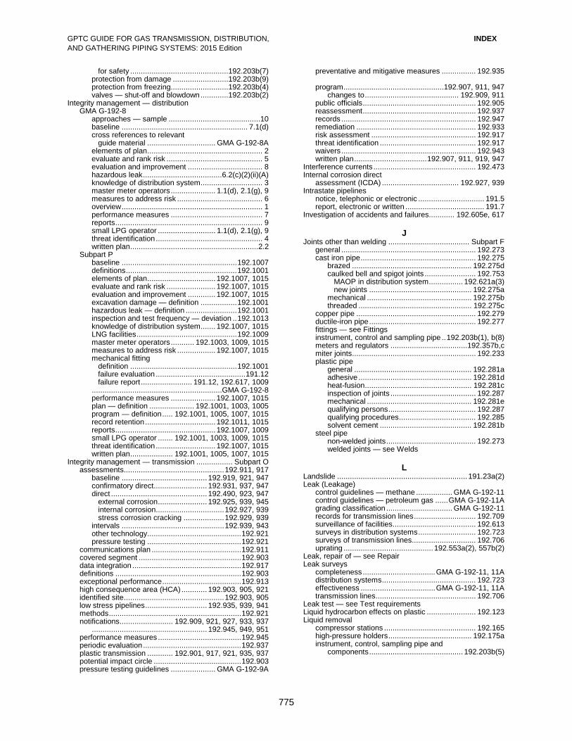
GPTC GUIDE FOR GAS TRANSMISSION, DISTRIBUTION, INDEX AND GATHERING PIPING SYSTEMS: 2015 Edition
775
for safety ..............................................192.203b(7) protection from damage ..........................192.203b(9) protection from freezing...........................192.203b(4) valves — shut-off and blowdown .............192.203b(2) Integrity management — distribution GMA G-192-8 approaches — sample ...........................................10 baseline ........................................................... 7.1(d) cross references to relevant guide material ................................ GMA G-192-8A elements of plan ...................................................... 2 evaluate and rank risk ............................................. 5 evaluation and improvement ................................... 8 hazardous leak ..................................... 6.2(c)(2)(ii)(A) knowledge of distribution system ............................. 3 master meter operators ..................... 1.1(d), 2.1(g), 9 measures to address risk ........................................ 6 overview .................................................................. 1 performance measures ........................................... 7 reports ..................................................................... 9 small LPG operator ........................... 1.1(d), 2.1(g), 9 threat identification .................................................. 4 written plan ............................................................2.2 Subpart P baseline ...................................................... 192.1007 definitions .................................................... 192.1001 elements of plan ................................ 192.1007, 1015 evaluate and rank risk ....................... 192.1007, 1015 evaluation and improvement ............. 192.1007, 1015 excavation damage — definition ................. 192.1001 hazardous leak — definition ........................ 192.1001 inspection and test frequency — deviation .. 192.1013 knowledge of distribution system ....... 192.1007, 1015 LNG facilities ............................................... 192.1009 master meter operators ........... 192.1003, 1009, 1015 measures to address risk .................. 192.1007, 1015 mechanical fitting definition .................................................. 192.1001 failure evaluation .......................................... 191.12 failure report ........................ 191.12, 192.617, 1009 ............................................................. GMA G-192-8 performance measures ..................... 192.1007, 1015 plan — definition ..................... 192.1001, 1003, 1005 program — definition ..... 192.1001, 1005, 1007, 1015 record retention ................................. 192.1011, 1015 reports ............................................... 192.1007, 1009 small LPG operator ....... 192.1001, 1003, 1009, 1015 threat identification ............................ 192.1007, 1015 written plan .................... 192.1001, 1005, 1007, 1015 Integrity management — transmission ................. Subpart O assessments............................................... 192.911, 917 baseline ........................................ 192.919, 921, 947 confirmatory direct......................... 192.931, 937, 947 direct ............................................. 192.490, 923, 947 external corrosion ....................... 192.925, 939, 945
internal corrosion ................................ 192.927, 939 stress corrosion cracking ................... 192.929, 939 intervals ................................................ 192.939, 943
other technology ............................................ 192.921 pressure testing ............................................ 192.921 communications plan .......................................... 192.911 covered segment ................................................ 192.903 data integration ................................................... 192.917 definitions ........................................................... 192.903 exceptional performance ..................................... 192.913 high consequence area (HCA) ............ 192.903, 905, 921 identified site ............................................... 192.903, 905 low stress pipelines ............................. 192.935, 939, 941 methods .............................................................. 192.921 notifications ......................... 192.909, 921, 927, 933, 937 ...................................................... 192.945, 949, 951 performance measures ....................................... 192.945 periodic evaluation .............................................. 192.937 plastic transmission ............ 192.901, 917, 921, 935, 937 potential impact circle ......................................... 192.903 pressure testing guidelines ..................... GMA G-192-9A
preventative and mitigative measures ................ 192.935 program ............................................... 192.907, 911, 947 changes to ............................................ 192.909, 911 public officials ..................................................... 192.905 reassessment ..................................................... 192.937 records ............................................................... 192.947 remediation ........................................................ 192.933 risk assessment ................................................. 192.917 threat identification ............................................. 192.917 waivers ............................................................... 192.943 written plan .................................. 192.907, 911, 919, 947 Interference currents ................................................ 192.473 Internal corrosion direct assessment (ICDA) .................................... 192.927, 939 Intrastate pipelines notice, telephonic or electronic ............................... 191.5 report, electronic or written ..................................... 191.7 Investigation of accidents and failures............ 192.605e, 617 J Joints other than welding ...................................... Subpart F general ............................................................... 192.273 cast iron pipe ...................................................... 192.275 brazed ........................................................ 192.275d caulked bell and spigot joints ........................ 192.753 MAOP in distribution system ................ 192.621a(3) new joints ................................................ 192.275a mechanical ................................................. 192.275b threaded ..................................................... 192.275c copper pipe ........................................................ 192.279 ductile-iron pipe .................................................. 192.277 fittings — see Fittings instrument, control and sampling pipe .. 192.203b(1), b(8) meters and regulators ....................................192.357b,c miter joints .......................................................... 192.233 plastic pipe general ....................................................... 192.281a adhesive ..................................................... 192.281d heat-fusion .................................................. 192.281c inspection of joints ........................................ 192.287 mechanical ................................................. 192.281e qualifying persons ......................................... 192.287 qualifying procedures .................................... 192.285 solvent cement ........................................... 192.281b steel pipe non-welded joints .......................................... 192.273 welded joints — see Welds L Landslide ............................................................. 191.23a(2) Leak (Leakage) control guidelines — methane ................. GMA G-192-11 control guidelines — petroleum gas ...... GMA G-192-11A grading classification ............................... GMA G-192-11 records for transmission lines ............................. 192.709 surveillance of facilities ....................................... 192.613 surveys in distribution systems ........................... 192.723 surveys of transmission lines.............................. 192.706 uprating .......................................... 192.553a(2), 557b(2) Leak, repair of — see Repair Leak surveys completeness .................................. GMA G-192-11, 11A distribution systems ............................................ 192.723 effectiveness ................................... GMA G-192-11, 11A transmission lines ............................................... 192.706 Leak test — see Test requirements Liquid hydrocarbon effects on plastic ....................... 192.123 Liquid removal compressor stations ........................................... 192.165 high-pressure holders ....................................... 192.175a instrument, control, sampling pipe and components ............................................ 192.203b(5)

GPTC GUIDE FOR GAS TRANSMISSION, DISTRIBUTION, INDEX AND GATHERING PIPING SYSTEMS: 2015 Edition
776
Listed specification definition ................................................................. 192.3 incorporation by reference ...................................... 192.7 LNG facility definition ................................................................. 191.3 incident ................................................................... 191.3 material defect ............................................... 191.23a(3) mechanical fitting failure reporting not required . 192.1009 safety-related condition ......................................... 191.23 Loading and external damage, protection against design ................................................................. 192.103 flexibility .............................................................. 192.159 instrument and control lines ..........................192.203b(9) pipelines ............................................................. 192.161 service lines ...................................................... 192.361d Location compressor buildings ........................................ 192.163a high-pressure bottle-type holders ........................ 192.177 valves distribution systems ...................................... 192.181 transmission lines ......................................... 192.179 Location class — see Class location Lowering pipeline — see Realignment Low-pressure distribution system definition ................................................................. 192.3 maximum allowable operating pressure ............ 192.623a minimum allowable operating pressure ............. 192.623b see also Distribution systems Low stress pipelines integrity management ......................... 192.935, 939, 941 M Mains definition ................................................................. 192.3 installation — see Installation test requirements — see Test requirements see also Distribution systems Maintenance requirements ....................................... 192.701 general ................................................................ 192.703 abandonment or deactivation of facilities ............ 192.727 accidental ignition, prevention of ......................... 192.751 caulked bell and spigot joints .............................. 192.753 compressor stations combustible materials, storage of .................. 192.735 procedural manual ........................................ 192.605 relief devices — inspection and testing ......... 192.731 distribution systems leak surveys and procedures ......................... 192.723 leaks — repair ............................................. 192.703c markers — mains and transmission lines ...... 192.707 procedural manual ................................ 192.603, 605 patrolling ....................................................... 192.721 pressure limiting and regulating stations inspection and testing ................................... 192.739 telemetering or recording gauges .................. 192.741 testing of relief devices .................................. 192.743 qualification of personnel .................................... 192.801 service lines — test requirements for reinstating . 192.725 transmission lines imperfections and damage — repair ............. 192.713 leak surveys .................................................. 192.706 leaks — repair ..................................... 192.703c, 717
markers — mains and transmission lines ..... 192.707 patrolling ....................................................... 192.705 procedural manual ........................................ 192.605 repair procedures — general ......................... 192.711 testing of repairs ........................................... 192.719 weld — repair ................................................ 192.715 valves distribution systems ...................................... 192.747 transmission lines ......................................... 192.745 vaults .................................................................. 192.749 Manual for operations, maintenance, and emergencies ................................................ 192.605
Manual service line shut-off valve ............................ 192.385 Markers — mains and transmission lines ................. 192.707 Marking of materials ................................................... 192.63 Master meter system definition ................................................................. 191.3 operator’s DIMP requirements ....... 192.1003, 1009, 1015 Material qualification, pipe and components ............... 192.51 general ................................................................. 192.53 plastic pipe ........................................................... 192.59 steel pipe .............................................................. 192.55 Material specifications, summary .................... GMA G-192-1 Maximum actual operating pressure and Maximum allowable operating pressure (MAOP) change in class location required study ............................................... 192.609 revision of MAOP .......................................... 192.611 confirmation for class location ............................ 192.611 definition ................................................................. 192.3 high-pressure distribution systems ..................... 192.621 increasing operating pressure substantially ........ 192.619 low-pressure distribution systems ....................... 192.623 MAOP, steel or plastic pipelines ......................... 192.619 see also Uprating Maximum hoop stress allowed during strength tests ................................................... 192.503c Mechanical leak clamp, transmission line repair ...... 192.717 Metering stations design factor — Class 1 and Class 2 locations . 192.111d Meters and regulators, customer general ............................................................... 192.351 installation .......................................................... 192.353 location ....................................................... 192.353, 357 operating pressure — meters ............................. 192.359 overpressure protection — service regulators design requirements ................................... 192.197a distribution systems over 60 psig ................ 192.197c distribution systems under 60 psig .............. 192.197b protection from damage ..................................... 192.355 vacuum or back pressure ........................... 192.355a vaults and pits ............................................ 192.355c vents ........................................................... 192.355b Metric units — table of units & conversion factors ............ GMA G-192-M Minimum allowable operating pressure — low-pressure distribution system ...................... 192.623b Mining activity .......................................................... 192.613 Miter joints ............................................................... 192.233 MOC (management of change) IMP process components ................................... 192.911 Initiating .............................................................. 192.911 Movement of in-service pipelines — see Realignment Mufflers — compressor stations ............................. 192.171e Municipality — definition ................................... 191.3, 192.3 Mutual aid — qualification of personnel .................... 192.801 N Natural risks ..... 191.23(a), 192.612, 613, 615, 705, 721, 917 ..................... 192. 943, 1007, 1015, GMA G-192-7, 8 Navigable waters – see Inland navigable waters Nominal wall thickness steel pipe ............................................................ 192.109 Nondestructive testing of welds ................................ 192.243 Notices – see Incidents see Safety-related condition reports

GPTC GUIDE FOR GAS TRANSMISSION, DISTRIBUTION, INDEX AND GATHERING PIPING SYSTEMS: 2015 Edition
Addendum 6, December 2016 777
O Odorization ............................................................... 192.625 chemical requirements ................................... 192.625c,d concentration in distribution lines ...................... 192.625a concentration in transmission lines ................... 192.625b concentration sampling test ............................... 192.625f master meter systems ....................................... 192.625f rate of introduction ............................................ 192.625e Offshore definition ................................................................. 191.3 filing condition reports ........................................... 191.27 gathering ................................................................. 191.1 Offshore pipelines definition ................................................................. 192.3 abandonment or deactivation of facilities ............ 192.727 class location .......................................................... 192.5 compressor stations, emergency shutdown ...... 192.167c corrosion control — see Corrosion control cover requirements ........................................... 192.327e design factor for steel pipe ............................192.111d(2) field repair damages and imperfections ........................ 192.713b leaks ........................................................... 192.717b installation ...................................................... 192.319b,c markers, exclusion of ........................................ 192.707b pipe riser on platform ....................................192.111d(2) protection from damage ...................................... 192.317 valves ............................................................... 192.179d weld repair and removal ................................. 192.245a,b Oil and gasoline tanks — compression stations ..... 192.735b OMB control number .................................................. 191.21 Onshore gathering ........................................................ 191.1 compliance requirements ........................................ 192.9 determination .......................................................... 192.8 type ......................................................................... 192.8 Operator definition ............................................. 191.3, 192.3 Operator Qualification (OQ) ................................... Subpart N abnormal operating condition .............................. 192.803 communication of changes ................................. 192.805 contractors .................................................. 192.801, 803 covered task ............................................... 192.803, 805 definitions ........................................................... 192.803 evaluations ......................................................... 192.803 categories ..................................................... 192.803 evaluator ....................................................... 192.803 intervals ........................................................ 192.805 observation ................................................... 192.803 work history ................................................... 192.803 four-part test ....................................................... 192.805 maintenance task................................................ 192.805 mutual aid ........................................................... 192.801 performance contributing to incident ................... 192.805 program .............................................................. 192.805 records................................................................ 192.807 Operating and maintenance plan .................... 192.603b, 605 amendments ..................................................... 192.603c records requirements ........................................ 192.603b Operating company — see Operator Operations requirements .......................................... 192.601 general .......................................................... 192.13, 603 OQ — see Operator Qualification Orange-peel bull plugs and swages ........................ 192.153c OSHA Letters .......................... 191.1, 192.1, GMA G-192-21 Outer Continental Shelf (OCS) ..................................... 192.1 Memorandum of Understanding between DOT and DOI ..................................... GMA G-192-19 Outlets, extruded ...................................................... 192.157 Overpressure protection general .............................................................. 192.195a capacity of relief devices ..................................... 192.201 compressor stations .......................................... 192.169a design requirements ........................................... 192.199 distribution system additional requirements ............................... 192.195b
operating under 60 psig with specified service regulators ..................... 192.197a operating at 60 psig or less with other service regulators ........................... 192.197b operating over 60 psig ............................... 192.197c maximum allowable operating pressure requirements .....................................192.619b, 621b see also Pressure limiting, regulating, and relieving stations P Patrolling distribution systems ............................................ 192.721 transmission lines ............................................... 192.705 Performance measures distribution integrity management ............. 192.1007, 1015, GMA G-192-8 transmission integrity management .................... 192.945 Person — definition ........................................... 191.3, 192.3 Petroleum gas systems general requirements ......................................... 192.11a definition ............................................................. 192.11c leak classification .................................. GMA G-192-11A leak control guidelines ........................... GMA G-192-11A vents and ventilation ........................................... 192.11b Pipe definition ................................................................. 192.3 end preparation ......................................... GMA G-192-5 table of specified minimum yield strengths.............................................. GMA G-192-2 Pipelines definition ................................................................. 192.3 integrity management — see Integrity management material defect................................................ 191.23a(4) test conditions ........................................... GMA G-192-9 unintended movement .................................... 191.23a(2) Pipeline facility — definition .............................. 191.3, 192.3 Plastic pipe above ground level ........................................... 192.321g bridge crossings ...................................... GMA G-192-21 casing requirements ................................. 192.321b,d,e,f clearance between mains and other structures 192.325c cover requirements — see Cover requirements damage prevention ............................................. 192.614 design general ......................................................... 192.121 flexibility ........................................................ 192.159 limitations ..................................................... 192.123 pressure of plastic fittings ............................. 192.193 supports and anchors ................................... 192.161 fittings, design pressure ..................................... 192.191 inspection/monitoring fittings with metal components ...... Subpart I, 192.475 joints ............................................................. 192.287 installation connections to mains .................................... 192.367 plastic pipe — general .................................. 192.321 service lines .......................................... 192.361, 375 valves ........................................................... 192.193 joining general ......................................................... 192.273 electrofusion ................................................. 192.281 heat fusion .................................................... 192.281 joints ...................................... 192.281, 283, 285, 287 unlike PE components .................................. 192.283 liquid hydrocarbon effects ................................... 192.123 MAOP ................................................. 192.619, 621, 623 material/pipe qualification ................. 192.59, Appendix B marking .......................................................... 192.63 pressure limitations .......................................... 192.123a qualification joining procedures ........................................ 192.283 persons to make joints .................................. 192.285 repair of defects or damage ................................ 192.311 re-use ................................................................. 192.59b

GPTC GUIDE FOR GAS TRANSMISSION, DISTRIBUTION, INDEX AND GATHERING PIPING SYSTEMS: 2015 Edition
Addendum 6, December 2016 778
tapping ................................................................ 192.627 temperature limitations ................. 192.123b, 325c, 513d testing ................................................................. 192.513 tracer wire ........................................................... 192.321 transmission — integrity management requirements ................. 192.901, 917, 921, 935, 937 uprating ............................................................... 192.557 valve installation ................................................. 192.193 wall thickness, minimum thermoplastic..................................... 192.123c, 321d thermosetting .............................................. 192.123d Pressure see Maximum allowable operating pressure see Minimum allowable operating pressure Pressure limiting and relief devices capacity tests of relief devices ............................ 192.743 design control piping — see Instrument, control, and sampling pipe materials .................................................. 192.199a,d petroleum gas systems — location of relief valve vents ........................................ 192.11b prevention of hammering .............................. 192.199f prevention of tampering, unauthorized operation .................................................. 192.199h protection from damage .............................. 192.199g valves .......................................................... 192.199b valve test requirement ................................. 192.199c vents ........................................................... 192.199e inspection and testing of relief devices compressor stations ...................................... 192.731 pressure limiting and regulating stations ....... 192.739 Pressure limiting, regulating, and relieving stations capacity tests of relief device .............................. 192.743 design capacity and set pressure requirements .. 192.201 design factor — Class 1 and Class 2 locations . 192.111d emergency shut-off valve — distribution system ........................................................ 192.181b inspection and testing ......................................... 192.739 recording gauges or telemetering required — distribution systems ...................................... 192.741 Prevention of accidental ignition ............................... 192.751 Procedural manual operations, maintenance and emergencies ......... 192.605 training ................................................................ 192.605 Property damage .......................................................... 191.3 Protection from hazards — see Hazards, protection from Public education ...................................................... 192.616 Publishing organizations, summary ................. GMA G-192-1 Purging general ................................................................ 192.629 abandoned facilities ............................................ 192.727 prevention of accidental ignition ........................ 192.751a
Q Qualification of personnel — see Operator Qualification
R Realignment — in-service pipeline ........................... 192.703 Records corrosion control ................................................. 192.491 explicit requirements, summary ............... GMA G-192-17 integrity management ..................... 192.947, 1011, 1015 procedural manual ............................................ 192.603b qualification of personnel .................................... 192.807 strength and leak test ......................................... 192.517 transmission lines ............................................... 192.709 uprating ............................................................. 192.553b welding procedure qualification ........................... 192.225 welds on transmission lines — nondestructive tests ..................................... 192.243f Rectifiers, inspection .............................................. 192.465b References and related sources, summary ..... GMA G-192-1
previously incorporated ........................... GMA G-192-1A Regulators — see Pressure limiting, regulating, and relieving stations Regulators, customer — see Meter and regulators Regulatory construction, rules of .............................. 192.151 Relief devices — see Pressure limiting and relief devices Remote control devices, compressor station, inspection and testing ....................................................... 192.731c Removal of defects — see Repair Repair immediate repair conditions................................ 192.933 leaks, hazardous .............................................. 192.703c plastic pipe ......................................................... 192.311 qualification of personnel .................................... 192.801 steel pipe arc burns — elimination ......................... 192.309c,d,e dents .................................................... 192.309b,d,e gouges..................................................... 192.309d,e transmission lines — general repair requirements permanent field repair imperfection and damage .......................... 192.713 leaks .......................................................... 192.717 welds ......................................................... 192.715 records of repair ........................................... 192.709 testing repair ................................................. 192.719 unsafe pipeline segments ................................. 192.703b welds — see Welds Report forms — distribution RSPA F 7100.1 Incident ........................... GMA G-191-2 RSPA F 7100.1-1 Annual Report .............. GMA G-191-3 RSPA F 7100.1-2 Mechanical Fitting Failure ................................................. GMA G-191-4 Report forms — transmission and gathering RSPA F 7100.2 Incident ........................... GMA G-191-5 RSPA F 7100.2-1 Annual Report ............... GMA G-191-6 Reports — see Incidents see Records see Safety-related condition report Rules of regulatory construction ................................. 192.15 S Safety Enhancement Program distribution ................................................. GMA G-192-8 Safety-related condition report determination of reporting requirements ....................................... GMA G-191-7 filing ..................................................................... 191.25 form — sample .......................................... GMA G-191-8 reporting ............................................................... 191.23 SCADA ................................................................ 192.3, 615 SCC (stress corrosion cracking) assessing for susceptibility to ............................. 192.613 direct assessment (SCCDA)....................... 192.929, 939 follow-up actions for indications of ...................... 192.613 mitigation ............................................................ 192.613 Scope Part 191 ................................................................. 191.1 Part 192 ................................................................. 192.1 Service lines Branched ............................................................ 192.383 casing................................................................ 192.361f cast iron and ductile-iron .................................... 192.373 connection to main general ......................................................... 192.367 cast iron or ductile-iron main ......................... 192.369 copper ................................................................ 192.377 cover requirements general ....................................................... 192.361a plastic pipe ................................................. 192.375a definition ................................................................. 192.3 installation general ......................................................... 192.361 into buildings .............................................. 192.361e under buildings ............................................ 192.361f manual shut-off valves ....................................... 192.385

GPTC GUIDE FOR GAS TRANSMISSION, DISTRIBUTION, INDEX AND GATHERING PIPING SYSTEMS: 2015 Edition
Addendum 6, December 2016 779
odorization .......................................................... 192.625 plastic ................................................................. 192.375 replaced .............................................................. 192.383 serving single family residence ........................... 192.383 steel, design pressure ......................................... 192.371 test conditions .......................................... GMA G-192-10 test requirements — see Test requirements valves excess flow .................................................. 192.381 location ......................................................... 192.365 requirements ................................................. 192.363 welder qualification ......................... 192.227, Appendix C Shall — definition ....................................................... 192.15 Shipping of pipe — see Transportation of pipe Shutting down facilities ........................................... 192.605b planned shutdown .................................... GMA G-192-12 Smart pigs ............................................................. 191.25(a) SMYS specified minimum yield strength — definition … .... 192.3 Spacing required for valves distribution systems ............................................ 192.181 transmission lines ............................................... 192.179 Standards and specifications incorporation by reference ...................................... 192.7 summary .................................................... GMA G-192-1 Starting up facilities ................................................ 192.605b State — definition .............................................. 191.3, 192.3 Steel pipe arc burns — elimination .............................. 192.309c,d,e corrosion control ............................................... Subpart I dents — elimination .................................... 192.309b,d,e design factor ....................................................... 192.111 design formula .................................................... 192.105 gouges and grooves — elimination ................ 192.309d,e longitudinal joint factor ........................................ 192.113 material qualification — see Material qualification nominal wall thickness ........................................ 192.109 repair .................................................................. 192.309 riser on platform ............................................192.111d(2) service lines — see Service lines temperature derating factor ................................. 192.115 temperature limitation ....................................... 192.105b yield strength ...................................................... 192.107 Strength test — see Test requirements Stress corrosion cracking — see SCC Stress intensification factors ..................................... 192.159 Subsidence due to mining ........................................ 192.613 Supplemental report ................................................. 191.15b Supports — see Anchors Surveillance of facilities .................................. 192.605e, 613
T
Tapping .................................................................... 192.151 crew qualifications for hot taps .................... 192.627, 801 Technical papers & publications, summary .................................................... GMA G-192-1 Telephonic notice incidents ................................................................. 191.5 worksheet .................................................. GMA G-191-1 Temperature derating factor — steel pipe ................................ 192.115 limitations copper or brass .......................................192.203b(3) flanges .......................................................... 192.147 meters ......................................................... 192.353c plastic pipe ........................................ 192.123a, 325c steel pipe .................................................... 192.105b Terms, commonly used — see Definitions see also Glossary Test leads, cathodic protection monitoring................ 192.471 Test requirements .................................................... 192.501 general ................................................................ 192.503 bottle-type holders leak .........................................................192.177b(5)
hydrostatic .............................................. 192.177b(4) compressor stations — 30% of SMYS or more 192.505b explicit requirements, summary ............... GMA G-192-17 field repair — transmission lines ......................... 192.719 pipelines 30 percent or more of SMYS ........................ 192.505 at or above 100 psig and below 30 percent of SMYS ........................ 192.507 below 100 psig .............................................. 192.509 plastic ........................................................... 192.513 records ............................................................... 192.517 regulator and measuring stations — 30% or more of SMYS ................................ 192.505b safety and environmental protection ................... 192.515 service lines new ............................................................... 192.511 reinstated ...................................................... 192.725 stress limitations in pipe ................................... 192.503c test medium ..................................................... 192.503b welds general ......................................................... 192.241 nondestructive test ..................................... 192.241b Test stations, cathodic protection monitoring ........... 192.469 Testing of welders — see Welder qualification Thermal expansion and contraction ................. 192.159, 161 Thermit welding on bottle-type holders ............... 192.177b(3) Threat identification — see Integrity management distribution ............................... GMA G-192-8, Subpart P transmission ....................................................... 192.917 Transmission lines casing................................................................. 192.323 cathodic protection — see Cathodic protection cover ................................................................ 192.327a definition ................................................................. 192.3 design — see Design of pipe installation — see Installation integrity management — see Integrity management — transmission leak surveys ....................................................... 192.706 maintenance — see Maintenance markers .............................................................. 192.707 odorization ........................................................ 192.625b patrolling ............................................................ 192.705 plastic .................................. 192.901, 917, 921, 935, 937 protection from hazards ...................................... 192.317 qualification of personnel .................................... 192.801 recordkeeping .................................................... 192.709 repair — see Repair strength test requirements — see Test requirements valves general — location and spacing .................... 192.179 blowdown valves ......................................... 192.179c maintenance ................................................. 192.747 welds — see Welds Transmission systems annual report ........................................................ 191.17 annual report form/instructions .................. GMA G-191-6 incident report ...................................................... 191.15 incident report form/instructions ................ GMA G-191-5 Transportation of gas — definition .................... 191.3, 192.3 Transportation of pipe ................................................ 192.65 Trenches .......................................................... 192.605(b)(9) Trenchless technologies, substructure damage prevention guidelines................................ GMA G-192-6

GPTC GUIDE FOR GAS TRANSMISSION, DISTRIBUTION, INDEX AND GATHERING PIPING SYSTEMS: 2015 Edition
Addendum 6, December 2016 780
U Uncased pipeline crossings of highways and railroads ............................................ GMA G-192-15 Underwater inspection — Gulf of Mexico .................. 192.612 Unintended movement ........................................ 191.23a(2) Unknown pipe specifications cast iron and ductile iron, uprating .................... 192.557d steel pipe ...................................................... Appendix B Uprating .................................................................... 192.551 general ................................................................ 192.553 cast iron pipe or ductile-iron pipe ...................... 192.557d cover requirements, cast iron and ductile iron .......................................192.557d (2) limitation on increase in MAOP ......................... 192.553d low-pressure distribution system ......................... 192.557 plastic pipe .......................................................... 192.557 records.............................................................. 192.553b steel pipe hoop stress 30% or more of SMYS ............... 192.555 hoop stress less than 30% of SMYS ............. 192.557 written plan ....................................................... 192.553c Used pipe general .................................................................. 192.53 plastic ................................................................. 192.59b steel .................................................................... 192.55c
V Valve assemblies design factor .................................................192.111b(4) Valves cast iron, flanged in steel pipelines ..................... 192.145 design general .......................................................... 192.145 service line .................................................... 192.363 excess flow ......................................................... 192.381 installation in plastic pipe .................................... 192.193 instrument and control piping — required ......192.203b(2) location of and spacing required distribution system ........................................ 192.181 service line .................................................... 192.365 transmission line ........................................... 192.179 maintenance distribution systems ...................................... 192.747 transmission lines ......................................... 192.745 manual service line shut-off ................................ 192.385 material limitations — compressor stations ....... 192.145d plastic pipe .......................................................... 192.193 regulator stations — required ............................ 192.181b Vaults abandonment ..................................................... 192.727f accessibility ........................................................ 192.185 drainage and waterproofing ............................ 192.189a,b electrical facilities .............................................. 192.189c maintenance ....................................................... 192.749 meters and regulators ....................................... 192.355c plastic pipe — installation ................................. 192.321b pressure limiting and relief device design requirements ...................................... 192.199 structural requirements ................................. 192.183 venting, ventilation and sealing ..................... 192.187 Vents and ventilation blowdown valves — compressor stations ......192.167a(2) buildings — compressor stations ........................ 192.173 casing ............................................................... 192.323d fuel gas manifold — compressor engine ........... 192.171d meters .............................................................. 192.353c petroleum gas systems ....................................... 192.11b relief valves general ...................................................... 192.199e,f compressor stations .................................... 192.169b service lines — installation under buildings ... 192.361f(3) service regulators ..................................... 192.355, 357d vaults .................................................................. 192.187 Vibration — control in pipeline ................................ 192.161a Voltage — measurement and interpretation ........... Subpart I
W Wall thickness copper pipe — minimum .................................. 192.125a plastic pipe — minimum ....................... 192.123c,d, 321d steel pipe — nominal .......................................... 192.109 Weather protection during welding .................................... 192.231 Websites, summary ........................................ GMA G-192-1 Welded branch connections ..................................... 192.155 Welder qualification compressor stations ......................................... 192.229a limitations ........................................................... 192.229 low-stress level pipe ...................................... Appendix C periodic tests — small service lines ............... Appendix C qualification tests ................................................ 192.227 requalification ............................................. 192.227, 229 Welds… ................................................................... 192.221 acceptability ..................................................... 192.241c anchors and supports .........................192.161d(1),(2),(3) bending of .......................................................... 192.313 branch connections ............................................ 192.155 components fabricated ....................................... 192.153 high-pressure bottle-type holders ................. 192.177b(3) inspection and testing ......................................... 192.241 miter welds ......................................................... 192.233 nondestructive tests general ......................................................... 192.243 records ........................................................ 192-243f welds requiring nondestructive tests ............. 192.241 preparation for welding ....................................... 192.235 protection from weather ...................................... 192.231 qualification of procedures general ......................................................... 192.225 records ....................................................... 192.225b repair general ......................................................... 192.245 transmission lines ......................................... 192.245 thermit welds on high-pressure bottle-type holders.................................................... 192.177b(3) Wrinkle bends in steel pipe ...................................... 192.315 Written procedures explicit requirements, summary ............... GMA G-192-17 Written reports ............................................................. 191.7
Y Yield strength specified minimum — definition .............................. 192.3


