Guide for Applying Process Safety In Projects · Web viewDocument Title: Guide for Applying...
49
Petroleum Development Oman L.L.C. Document Title: Guide for Applying Process Safety in Projects Document ID GU-648 Document Type Guideline Security Unrestricted Discipline Technical Safety Engineering Owner MSE4 – Head of Technical Safety Engineering Issue Date 15 th December 2010 Revision 1.0
Transcript of Guide for Applying Process Safety In Projects · Web viewDocument Title: Guide for Applying...
Petroleum Development Oman L.L.C.
Document Title: Guide for Applying Process Safety in Projects
Document ID GU-648
Document Type Guideline
Security Unrestricted
Discipline Technical Safety Engineering
Owner MSE4 – Head of Technical Safety Engineering
Issue Date 15th December 2010
Revision 1.0

Petroleum Development Oman LLC Revision: 1.0Effective: Dec-10
This page was intentionally left blank
Page 2 GU-648 – Guide for Applying Process Safety in Projects Printed 15/12/10
The controlled version of this CMF Document resides online in Livelink®. Printed copies are UNCONTROLLED.
This document is the property of Petroleum Development Oman, LLC. Neither the whole nor any part of this document may be disclosed to others or reproduced, stored in a retrieval system, or transmitted in any form by any means (electronic, mechanical, reprographic recording or otherwise) without prior written consent of the owner.
Petroleum Development Oman LLC Revision: 1.0Effective: Dec-10
i Document AuthorisationAuthorised For Issue 15th December 2010
Page 3 GU-648 – Guide for Applying Process Safety in Projects Printed 15/12/10
The controlled version of this CMF Document resides online in Livelink®. Printed copies are UNCONTROLLED.
Petroleum Development Oman LLC Revision: 1.0Effective: Dec-10
ii Revision HistoryThe following is a brief summary of the 4 most recent revisions to this document. Details of all revisions prior to these are held on file by the issuing department.
Revision No.
Date Author Scope / Remarks
1.0 Dec-10 Ian Jewitt (MSE4)/yaseen Al Lawati (UOM6)
New Issue
Draft Oct-10 Robin Norman UOP6 MSE4 Comments added
iii Related Corporate Management Frame Work (CMF) Documents
The related CMF Documents in Appendix 1 can be retrieved from the Corporate Business Control Documentation Register CMF.
Page 4 GU-648 – Guide for Applying Process Safety in Projects Printed 15/12/10
The controlled version of this CMF Document resides online in Livelink®. Printed copies are UNCONTROLLED.
Petroleum Development Oman LLC Revision: 1.0Effective: Dec-10
TABLE OF CONTENTS
1 Introduction....................................................................................................................... 6
1.1 Background................................................................................................................. 6
1.2 Purpose....................................................................................................................... 6
1.3 Objective..................................................................................................................... 6
1.4 Distribution / Target Audience......................................................................................6
1.5 Review and Improvement.............................................................................................7
1.6 Step-out Approval........................................................................................................7
2 Roles and Responsibilities.................................................................................................8
2.1 Risk Management........................................................................................................8
2.2 Design and Construction..............................................................................................8
3 Process Safety Management.............................................................................................9
4 The Objectives of AI-PS in Projects.................................................................................11
4.1 People and Systems..................................................................................................11
4.2 Design Integrity..........................................................................................................12
4.3 Technical Integrity......................................................................................................13
4.4 Operating Integrity.....................................................................................................14
5 Project Phases................................................................................................................15
5.1 Identify.......................................................................................................................15
5.2 Assess.......................................................................................................................16
5.3 Select........................................................................................................................ 18
5.4 Define........................................................................................................................21
5.5 Execute..................................................................................................................... 24
6 Process Safety Basic Requirements................................................................................31
Appendix 1 – Reference Material............................................................................................32
Appendix 2 – Abbreviations....................................................................................................34
Appendix 3 – End of Delivery Map (to be developed)..............................................................35
Page 5 GU-648 – Guide for Applying Process Safety in Projects Printed 15/12/10
The controlled version of this CMF Document resides online in Livelink®. Printed copies are UNCONTROLLED.
Petroleum Development Oman LLC Revision: 1.0Effective: Dec-10
1 Introduction
1.1 BackgroundAsset Integrity – Process Safety (AI-PS) is about prevention and mitigation of incidents (such as fire or explosion) that result from unintentional release of energy or hazardous substances contained in the process assets we operate.
Successful AI-PS management is based on four principles:
1. Committing to process safety
2. Understanding process hazards and risk
3. Managing process risk to ALARP
4. Learning from experience.
These principles are applicable to all phases of the Opportunity Realisation Process (ORP).
1.2 PurposeThis guideline will be part of the Project Delivery documentation and its aim is to provide clarity with regards to AI-PS requirements throughout the phases from project identification to execution. It does not add any new processes or requirements to existing ORP deliverables, but extracts from the existing ORP documentation all the relevant information necessary to meet the AI-PS requirements at handover. It also provides further clarity with regards to the assurance processes which underpin the project team’s ability to demonstrate that AI-PS requirements are met at the end of every project phase. This will allow PDO to make the statement that “Our Asset is Safe and we know it” after each project phase.
Delivery of AI-PS requires that all major and high risk hazards (Highs and 5’s on the risk Assessment Matrix) are identified and mitigated against using the Hazard and Effects Management Process (HEMP). The systems and their subsidiary components critical to managing risks must be properly designed, procured, built, installed, tested and maintained such that the risk of a major or high risk accident event is ALARP. The HSE case (SP-2062 - HSE Specification: Specifications for HSE Cases) is the main vehicle to demonstrate ALARP and is a fundamental AI-PS tool for the project manager and project team.
1.3 ObjectiveThe main objective of this guideline is to explain the key AI-PS objectives and deliverables throughout the project phases that demonstrate the facility is fit for the safe introduction of process fluids and that systems, processes and procedures are in place so that AI-PS can be safeguarded in the subsequent operate phase.
1.4 Distribution / Target AudienceThis document provides a consistent guide to Project Managers, Project Engineers and Project Teams in the establishment of AI-PS throughout the project phases.
Page 6 GU-648 – Guide for Applying Process Safety in Projects Printed 15/12/10
The controlled version of this CMF Document resides online in Livelink®. Printed copies are UNCONTROLLED.

Petroleum Development Oman LLC Revision: 1.0Effective: Dec-10
1.5 Review and ImprovementResponsibility for the upkeep of the Document shall be with the CFDH Technical Safety Engineering (Owner of this guideline). Changes to this document shall only be authorised and approved by the Owner.
Users of the Document who identify inaccuracy or ambiguity can notify the Custodian or his/her delegate and request changes be initiated. The Requests shall be forwarded to the Custodian.
The Document Owner and the Document Custodian should ensure review and re-verification of this procedure every 3 years.
1.6 Step-out ApprovalNot applicable to this guideline.
Page 7 GU-648 – Guide for Applying Process Safety in Projects Printed 15/12/10
The controlled version of this CMF Document resides online in Livelink®. Printed copies are UNCONTROLLED.
Petroleum Development Oman LLC Revision: 1.0Effective: Dec-10
2 Roles and Responsibilities
2.1 Risk ManagementThe Project Manager should be Accountable for 1 – 7 below:
1. Identify and document Hazards with RAM red and yellow 5A and 5B Process Safety risks for existing and new Assets.
2. Manage identified ALARP.
3. Manage the competence of employees in HSE (Process Safety) Critical Positions.
4. Manage the fitness to work of employees.
5. Verify that Contract Holders monitor the HSE (Process Safety) requirements of the contract that are relevant to the competence and fitness to work of contractor staff.
6. Provide supervision of HSE (Process Safety) Critical Activities appropriate to:
the complexity of the activity including multiple concurrent tasks, and non-routine and unexpected activities; and
the competence of the individuals performing the activity.
7. Develop a Statement of Fitness for the Assets before starting or commissioning a new Asset or a modification to an existing Asset;
2.2 Design and ConstructionThe Project Manager should be Accountable for 8 – 12 below:
8. Establish Technical Integrity in design and construction.
9. Design and construct new Assets and make modifications to existing Assets to meet the SHALL [PS] requirements identified in PDO specifications and PDO-adopted Shell DEPs, or seek a derogation from the TA-1.
10. Meet Process Safety Basic Requirements identified in this guideline.
11. Create, make available and maintain the documentation for Safety Critical Equipment (SCE), including data and drawings that are critical to managing Process Safety.
12. Perform Pre-Start Up Audits (PSUA) for new Assets and for modifications to existing Assets.
Page 8 GU-648 – Guide for Applying Process Safety in Projects Printed 15/12/10
The controlled version of this CMF Document resides online in Livelink®. Printed copies are UNCONTROLLED.

Petroleum Development Oman LLC Revision: 1.0Effective: Dec-10
3 Process Safety ManagementProcess Safety Management is about prevention and mitigation of incidents (such as fire or explosion) that result from unintentional release of energy or hazardous substances contained in the process assets we operate.
Successful Process Safety Management is based on four principles:
Committing to process safety
Understanding process hazards and risk
Managing process risk to ALARP
Learning from experience.
Process safety commitment involves developing and sustaining a culture that embraces process safety; identifying, understanding and complying with codes, standards, regulations, and laws; establishing and continually enhancing organizational competence; and engaging all stakeholders, including employees, contractors, and neighbours.
To understand hazards and risk, the focus is on collecting, documenting, and maintaining process safety knowledge in documents such as EORDs, asset registers and ‘as built drawings’; and conducting hazard identification and risk analysis studies such as HAZID, HAZOP, IPF and Fire & Explosion Analysis (FERM). These areas are relevant in design and engineering as well as later in operation.
The management of process safety risk is made up of many elements.
Operating integrity is demonstrated;
by operating in accordance with plant start up and shut down procedures;
following the Permit to Work system and associated safe systems of work;
operating within design envelopes; conducting operations activities in accordance with recognised good practice;
signing Statements of Fitness before starting up operations;
and maintaining emergency preparedness.
Technical integrity is demonstrated;
by executing work activities to ensure that equipment is fabricated and installed in accordance with specifications;
and that it is maintained and inspected so that it remains fit for service over its entire life cycle.
Broader elements of managing risk include;
managing contractors to ensure that contractors are not exposed to unrecognized hazards or undertake activities that present unknown or intolerable risk;
providing training and conducting related activities to ensure reliable human performance at all levels of the organization;
and recognizing and managing changes.
Design integrity is also an aspect of reducing process safety risk to ALARP. In most situations, compliance to PDO adopted specifications and practices will be sufficient. However, this may not always be the case and the application of good engineering principles, risk assessment and addressing societal concerns (the potential for multiple fatalities) may also be necessary to achieve ALARP risk in design.
Page 9 GU-648 – Guide for Applying Process Safety in Projects Printed 15/12/10
The controlled version of this CMF Document resides online in Livelink®. Printed copies are UNCONTROLLED.
Petroleum Development Oman LLC Revision: 1.0Effective: Dec-10
Learning from incidents involves investigating process safety incidents to identify and address the root causes; applying lessons from incidents that occur at other facilities within PDO and within the industry; measuring performance and striving to continuously improve in areas that have been determined to be risk significant; auditing process safety management systems; and holding periodic management reviews to determine if the management systems are working as intended and if the work activities are helping the facility effectively manage risk.
Page 10 GU-648 – Guide for Applying Process Safety in Projects Printed 15/12/10
The controlled version of this CMF Document resides online in Livelink®. Printed copies are UNCONTROLLED.
Petroleum Development Oman LLC Revision: 1.0Effective: Dec-10
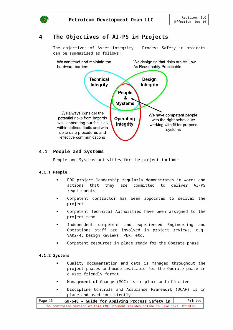
4 The Objectives of AI-PS in ProjectsThe objectives of Asset Integrity – Process Safety in projects can be summarised as follows;
4.1 People and SystemsPeople and Systems activities for the project include:
4.1.1 People PDO project leadership regularly demonstrates in words and actions that they
are committed to deliver AI-PS requirements
Competent contractor has been appointed to deliver the project
Competent Technical Authorities have been assigned to the project team
Independent competent and experienced Engineering and Operations staff are involved in project reviews, e.g. VAR2-4, Design Reviews, PER, etc.
Competent resources in place ready for the Operate phase
4.1.2 Systems Quality documentation and data is managed throughout the project phases and
made available for the Operate phase in a user friendly format
Management of Change (MOC) is in place and effective
Discipline Controls and Assurance Framework (DCAF) is in place and used consistently
QA/QC systems are in place and adhered to
Regular assurance of AI-PS deliverables takes place and results are captured in the HSE Case
Clear set of AI-PS metrics in place at project level
Lessons are applied from Process Safety incidents and assurance findings at other facilities within PDO and within the industry
Page 11 GU-648 – Guide for Applying Process Safety in Projects Printed 15/12/10
The controlled version of this CMF Document resides online in Livelink®. Printed copies are UNCONTROLLED.

Petroleum Development Oman LLC Revision: 1.0Effective: Dec-10
Process Safety actions (e.g. from HEMP studies, project reviews, TI verification, etc.) are tracked and records are maintained to demonstrate closure by competent Technical Authorities
4.2 Design IntegrityDesign Integrity is achieved through compliance to good practice (i.e. PDO specifications and adopted Shell DEPs) and application of HEMP (e.g. HAZID, HAZOP, IPF assessment, FEA, HSE Case, etc.) to ensure the risk is reduced to ALARP.
The ALARP demonstration process can involve varying degrees of attention which will depend on the nature of the hazard, the extent of the risk and the control measures to be adopted. The greater the initial level of risk under consideration, the greater the degree of rigour PDO requires of the arguments claiming to show that those risks have been reduced to ALARP. However, Project Managers should not be overburdened if such rigour is not necessary.
Where risks are required to be reduced to ALARP:
Project Managers may accept the application of relevant good practice in an appropriate manner as a sufficient demonstration of part or whole of an ALARP assessment;
discipline CFDH’s do not normally accept a lower standard of protection than would be provided by the application of current good practice; and
discipline CFDH’s will, where a different approach to controlling risks is proposed, seek assurance from the Project Manager that the risks are no greater than that those which would have been present through adoption of good practice and so are ALARP for that different approach.
Compliance with relevant good practice alone may be sufficient to demonstrate that risks have been reduced to ALARP. However, depending on the level of risk and complexity of the situation, it is also possible that meeting good practice alone may not be sufficient to reduce risks to ALARP.
Page 12 GU-648 – Guide for Applying Process Safety in Projects Printed 15/12/10
The controlled version of this CMF Document resides online in Livelink®. Printed copies are UNCONTROLLED.
Petroleum Development Oman LLC Revision: 1.0Effective: Dec-10
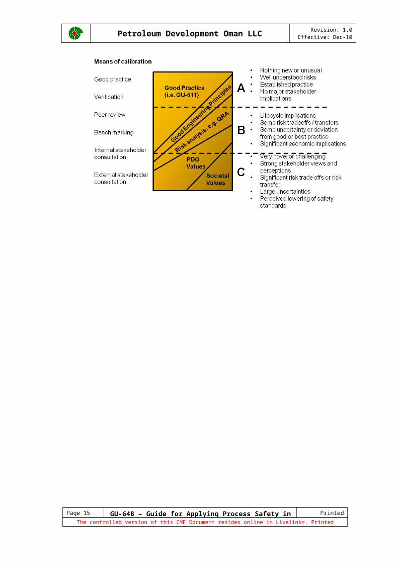
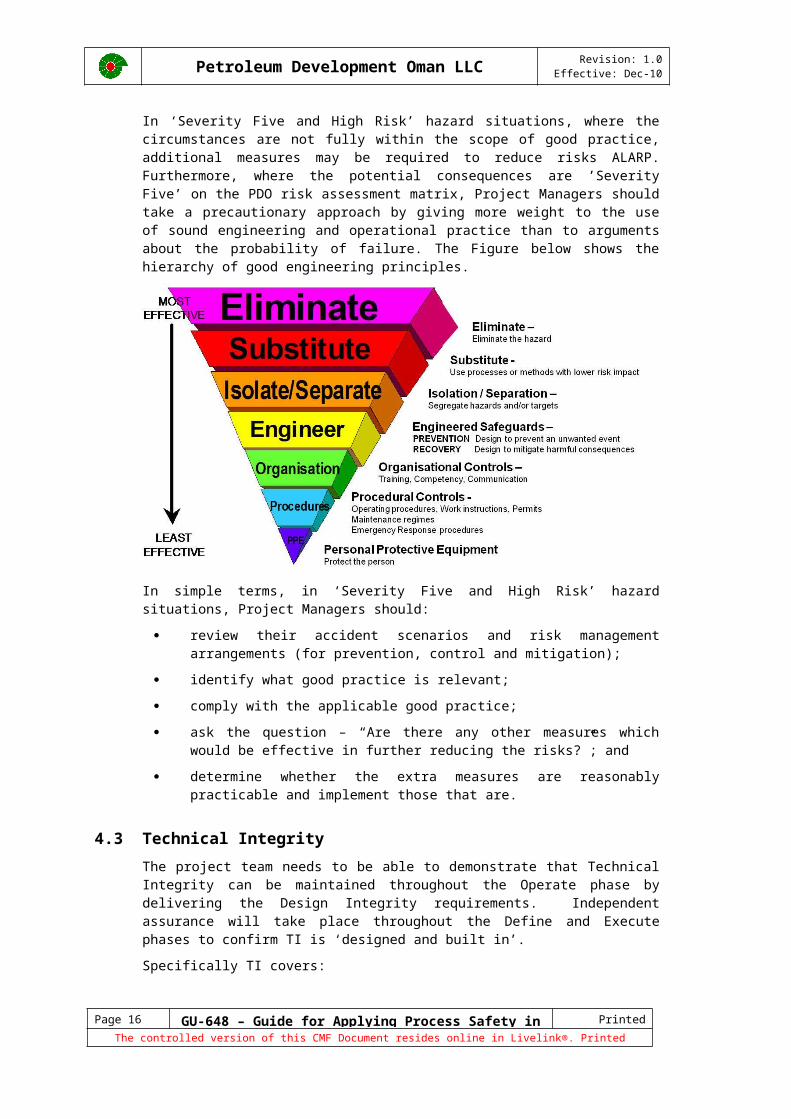
In ‘Severity Five and High Risk’ hazard situations, where the circumstances are not fully within the scope of good practice, additional measures may be required to reduce risks ALARP. Furthermore, where the potential consequences are ’Severity Five’ on the PDO risk assessment matrix, Project Managers should take a precautionary approach by giving more weight to the use of sound engineering and operational practice than to arguments about the probability of failure. The Figure below shows the hierarchy of good engineering principles.
In simple terms, in ‘Severity Five and High Risk’ hazard situations, Project Managers should:
review their accident scenarios and risk management arrangements (for prevention, control and mitigation);
identify what good practice is relevant;
comply with the applicable good practice;
ask the question – “Are there any other measures which would be effective in further reducing the risks?”; and
determine whether the extra measures are reasonably practicable and implement those that are.
4.3 Technical IntegrityThe project team needs to be able to demonstrate that Technical Integrity can be maintained throughout the Operate phase by delivering the Design Integrity requirements. Independent assurance will take place throughout the Define and Execute phases to confirm TI is ‘designed and built in’.
Specifically TI covers:
SCE hardware barriers identified and functionality assured through TI verification against performance standards during design, procurement, construction and commissioning.
Maintenance / inspection programme in place for SCE’s.
Management Systems (SAP-PM / QM) fully populated & tested and consistent with critical as-built documents and drawings.
Page 13 GU-648 – Guide for Applying Process Safety in Projects Printed 15/12/10
The controlled version of this CMF Document resides online in Livelink®. Printed copies are UNCONTROLLED.
Petroleum Development Oman LLC Revision: 1.0Effective: Dec-10
4.4 Operating IntegrityWhile Operating Integrity refers to the way that an asset is operated, Projects have a key role to play in this regard by ensuring that assets are delivered in such a way to support safe operations. Key examples include:
Human factors issues for process safety have been addressed, e.g. ease of access to critical manual valves, alarm rationalisation, control room layout, etc.
Operating integrity envelopes have been identified
Future operations staff involved in engineering and design
Commissioning and Start-Up (CSU) documents in place
Process knowledge delivered, e.g. Critical as-built drawings, critical operating documentation, etc.
Operations Management System set up (trip and alarm, PTW, plant operating procedures, ER procedures, key registers and communications protocols)
Statement of Fitness in the Operations HSE Case signed off
Page 14 GU-648 – Guide for Applying Process Safety in Projects Printed 15/12/10
The controlled version of this CMF Document resides online in Livelink®. Printed copies are UNCONTROLLED.
Petroleum Development Oman LLC Revision: 1.0Effective: Dec-10
5 Project PhasesThe Opportunity Realisation Process (ORP) is split into six phases punctuated by decision gates. Each phase has clear milestones and decision gates, activities, deliverables and decision requirements. The phases are:
This guideline follows the six ORP phases and details what deliverables need to be achieved at each decision gate, in order to meet the AI-PS requirements at the end of the execute phase.
5.1 Identify The Identify phase is the first step of the project cycle and evaluates if we understand what we’re getting ourselves into and should we spend resources in assessment of this opportunity.
The following DCAF deliverables for the Identify Phase have critical AI-PS content:
Deliverable ATA RTA(s)
Risk Register Field development Surface production, HSE
HSE & SD Plan HSE (technical safety)
PCAP Field development
5.1.1 Risk RegisterThe process looks at the key deliverables of the project and threats to success and any opportunities identified. AI-PS threats shall be transferred to a Risk Register which is a live document updated at each phase of the project. All actions are assigned to an action party and given a due date and risk owner.
Management of the identified risks is primarily about adopting a structured methodology of working that ensures risks are identified, understood, agreed, communicated and acted upon in a timely and consistent manner. Risk Management must be steered by the project leadership and actively used to support the decision making process.
5.1.2 HSE & SD PlanThe HSE & SD plan specifies studies and activities to be conducted at different stages of the project to meet the HSE objectives, including the HEMP studies required to deliver Design Integrity. It should also describe the plan of how AI-PS People and Systems objectives that are not covered by other project plans would be met, e.g. commitment to AI-PS, AI-PS metrics, learning from experience, AI-PS action tracking, etc. This plan must be updated at each project phase.
Page 15 GU-648 – Guide for Applying Process Safety in Projects Printed 15/12/10
The controlled version of this CMF Document resides online in Livelink®. Printed copies are UNCONTROLLED.
Petroleum Development Oman LLC Revision: 1.0Effective: Dec-10
5.1.3 Project Controls and Assurance Plan (PCAP)Discipline Controls and Assurance Framework (DCAF) standardises the framework in which Quality Control (QC) and Quality Assurance (QA) of discipline decisions and deliverables is conducted. DCAF is applicable across all disciplines and all ORP phases. DCAF will ensure that each discipline has a standard, which lists the decisions and deliverables the discipline contributes to each phase of the ORP, plus the required authority level for sign off. DCAF delegates the Technical Authority (TA) to take discipline decisions, or signing off discipline deliverables, to qualified individuals in a rigorous and auditable manner. The project team needs to ensure that this is captured in the Project Controls and Assurance Plan (PCAP).
The PCAP sets out an agreed series of activities and deliverables that are designed to ensure the quality of the emerging decisions at each phase of the project. The PCAP should demonstrate that competent TAs have been assigned to the project. AI-PS key deliverables and assurance events should be determined and included in the PCAP.
There are three elements in a Project Controls & Assurance Plan:
Key deliverables: there are a number of plans, reports and other documents that are mandatory elements of the ORP. In creating the PCAP, the Project Manager and Decision Review Board (DRB) must first address these deliverables and determine how they are applicable to their project.
Key assurance events: the PCAP must include the mandatory assurance events under the ORP, such as Value Assurance Reviews (VARs) before each Decision Gate.
Discretionary assurance events: in addition to the mandatory deliverables and events, there are a number of discretionary activities and tools. In developing the PCAP, the Decision Executive (DE)/DRB and Project Team should consider which discretionary events can contribute to the value of the project, but should avoid overloading the PCAP unnecessarily. An externally facilitated AI-PS Health check may be one of these discretionary assurance events.
5.2 AssessDecision Gate 2 at the end of the Assess Phase confirms the feasibility of the development and that there is a high enough likelihood of success.
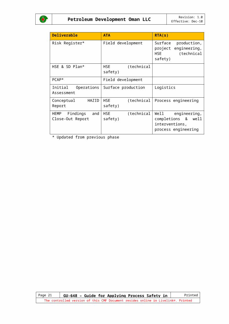
The following DCAF deliverables for the Assess phase have critical AI-PS content:
Deliverable ATA RTA(s)
Risk Register* Field development Surface production, project engineering, HSE (technical safety)
HSE & SD Plan* HSE (technical safety)
PCAP* Field development
Initial Operations Assessment
Surface production Logistics
Conceptual HAZID Report HSE (technical safety) Process engineering
HEMP Findings and Close-Out Report
HSE (technical safety) Well engineering, completions & well interventions, process engineering
* Updated from previous phase
Page 16 GU-648 – Guide for Applying Process Safety in Projects Printed 15/12/10
The controlled version of this CMF Document resides online in Livelink®. Printed copies are UNCONTROLLED.
Petroleum Development Oman LLC Revision: 1.0Effective: Dec-10
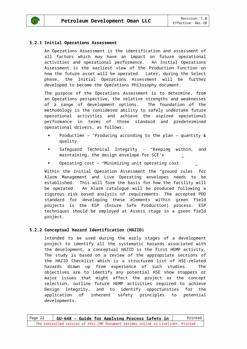
5.2.1 Initial Operations Assessment An Operations Assessment is the identification and assessment of all factors which may have an impact on future operational activities and operational performance. An Initial Operations Assessment is the earliest view of the Production Function on how the future asset will be operated. Later, during the Select phase, the Initial Operations Assessment will be further developed to become the Operations Philosophy document.
The purpose of the Operations Assessment is to determine, from an Operations perspective, the relative strengths and weaknesses of a range of development options. The foundation of the methodology is the considered ability to safely undertake future operational activities and achieve the aspired operational performance in terms of three standard and predetermined operational drivers, as follows:
Production – “Producing according to the plan – quantity & quality”
Safeguard Technical Integrity – “Keeping within, and maintaining, the design envelope for SCE’s”
Operating cost – “Minimizing unit operating cost”
Within the Initial Operation Assessment the “ground rules” for Alarm Management and Live Operating envelopes needs to be established. This will form the basis for how the facility will be operated. An Alarm catalogue will be produced following a rigorous risk based analysis of requirements. The accepted PDO standard for developing these elements within green field projects is the ESP (Ensure Safe Production) process. ESP techniques should be employed at Assess stage in a green field project.
5.2.2 Conceptual Hazard Identification (HAZID)Intended to be used during the early stages of a development project to identify all the systematic hazards associated with the development, a conceptual HAZID is the first HEMP activity. The study is based on a review of the appropriate sections of the HAZID Checklist which is a structured list of HSE-related hazards drawn up from experience of such studies. The objectives are to identify any potential HSE show stoppers or major issues that might affect the project or the concept selection, outline future HEMP activities required to achieve Design Integrity, and to identify opportunities for the application of inherent safety principles to potential developments.
5.2.3 HEMP Findings and Close-Out ReportThe HEMP Findings and Close-Out Report should summarise the key findings and recommendations / actions from the HEMP studies completed during this phase. During the Assess phase, this typically is limited to the Conceptual HAZID, but may include the findings of additional HEMP studies resulting from the HAZID.
In later phases, the HEMP Findings and Close-Out Report typically include Fire & Explosion Assessments, QRA, etc. HEMP studies that typically generate a large number of actions such as HAZOP and SIL assessments typically have their own dedicated HEMP Close-Out reports.
Page 17 GU-648 – Guide for Applying Process Safety in Projects Printed 15/12/10
The controlled version of this CMF Document resides online in Livelink®. Printed copies are UNCONTROLLED.

Petroleum Development Oman LLC Revision: 1.0Effective: Dec-10
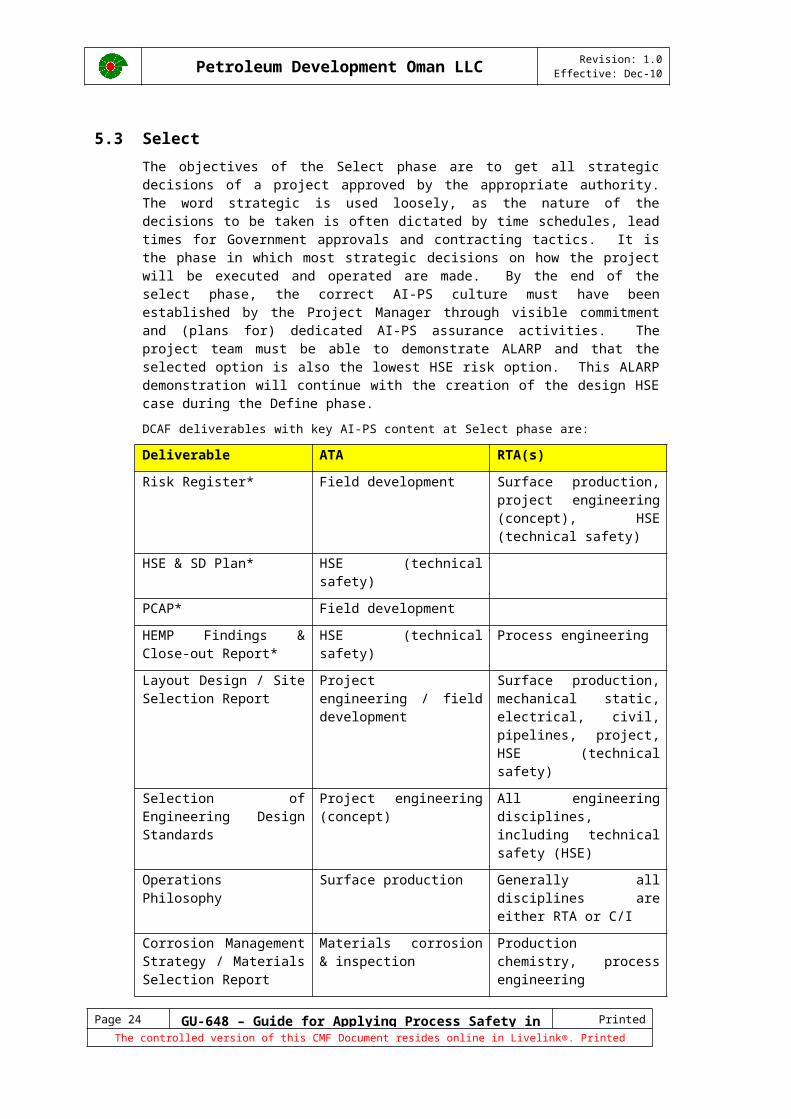
5.3 Select The objectives of the Select phase are to get all strategic decisions of a project approved by the appropriate authority. The word strategic is used loosely, as the nature of the decisions to be taken is often dictated by time schedules, lead times for Government approvals and contracting tactics. It is the phase in which most strategic decisions on how the project will be executed and operated are made. By the end of the select phase, the correct AI-PS culture must have been established by the Project Manager through visible commitment and (plans for) dedicated AI-PS assurance activities. The project team must be able to demonstrate ALARP and that the selected option is also the lowest HSE risk option. This ALARP demonstration will continue with the creation of the design HSE case during the Define phase.
DCAF deliverables with key AI-PS content at Select phase are:
Deliverable ATA RTA(s)
Risk Register* Field development Surface production, project engineering (concept), HSE (technical safety)
HSE & SD Plan* HSE (technical safety)
PCAP* Field development
HEMP Findings & Close-out Report*
HSE (technical safety) Process engineering
Layout Design / Site Selection Report
Project engineering / field development
Surface production, mechanical static, electrical, civil, pipelines, project, HSE (technical safety)
Selection of Engineering Design Standards
Project engineering (concept)
All engineering disciplines, including technical safety (HSE)
Operations Philosophy Surface production Generally all disciplines are either RTA or C/I
Corrosion Management Strategy / Materials Selection Report
Materials corrosion & inspection
Production chemistry, process engineering
ALARP Demonstration Report
HSE (technical safety) Generally all disciplines are either RTA or C/I
Detailed HAZID Report HSE (technical safety) Generally all disciplines are either RTA or C/I
Concept Risk Assessment HSE (technical safety) Process engineering
HSE Philosophy HSE (technical safety) Surface production, project engineering (concept)
Fire and Explosion Assessment
HSE (technical safety) Process engineering
Technical Integrity Verification Report
Field development Project engineering (concept), HSE
Process Safeguarding Report
Process engineering
Page 18 GU-648 – Guide for Applying Process Safety in Projects Printed 15/12/10
The controlled version of this CMF Document resides online in Livelink®. Printed copies are UNCONTROLLED.
Petroleum Development Oman LLC Revision: 1.0Effective: Dec-10
Deliverable ATA RTA(s)
OR&A Plan Surface production Maintenance & integrity, project engineering (concept)
* Updated from previous phase
5.3.1 Site Selection and Layout DesignThe initial site selection should be based on exposure from uncontrollable factors, such as floods, earthquakes, local population, tidal waves, subsidence, hurricanes, major wadis, and adjacent hazardous facilities.
The process hazards and effects should be assessed to establish the separation distance required between process units and equipment.
5.3.2 Selection of Engineering Design StandardsOne of the key elements of achieving Design Integrity is following good practice in design and engineering. In PDO, good practice encompasses the PDO engineering specifications and adopted Shell DEPs, which are identified in the PDO Guide to Engineering Standards and Procedures (GU-611). Variance from the listed standards requires the approval of the relevant discipline CFDH. Varying from standards that include SHALL [PS] requirements will only be accepted if supported by an ALARP demonstration.
5.3.3 Operations PhilosophyThe Operations Philosophy covers all aspects of the future operation and is developed from the Initial Operations Assessment. It provides the framework to ensure facility design matches how the asset is to be managed, operated, maintained, staffed and supported. The philosophy should describe how relevant People and Systems, operate passé Technical Integrity and Operating Integrity objectives will be achieved. It is essential that Operations Philosophy is developed in parallel with the concept selection work to ensure that this alignment exists. Intended readers during a project’s development phases are designers and future operators and during steady state operation technical and operational personnel.
5.3.4 Corrosion Management FrameworkThe Process Containment barrier is a key barrier in preventing an AI-PS incident. Facilities are exposed, both internally and externally, to corrosive environments. Therefore a Corrosion Management Framework must be established to identify, quantify and control degradation (corrosion) threats in order to safeguard the integrity of the Process Containment barrier throughout the life cycle of the asset.
5.3.5 ALARP DemonstrationThe Concept Selection Report (CSR) forms the basis for the engineering activities in the Define phase. It clarifies the context in which the selection decision has been made, the data that have been used, the alternatives that have been studied, and the values and trade- offs between alternatives. The purpose of the HSE content of the CSR is to demonstrate that there has been a systematic application of HEMP during the Identify & Assess and Select phases for each option being considered and to confirm that the lowest risk option has been actively sought and selected; or alternatively, demonstrate that the cost/effort required to adopt the lowest risk concept is grossly disproportionate to the benefit (ALARP).
For very large or complex projects, the ALARP demonstration may be a separate report, and the summarised in the CSR.
5.3.6 Detailed HAZID ReportThe detailed HAZID study takes place later once design options have been identified but before any final concept decisions have been made. A significant number of
Page 19 GU-648 – Guide for Applying Process Safety in Projects Printed 15/12/10
The controlled version of this CMF Document resides online in Livelink®. Printed copies are UNCONTROLLED.
Petroleum Development Oman LLC Revision: 1.0Effective: Dec-10
preliminary documents and drawings will be available for each design option, e.g. PFS, mass balance data, plot layout, process and project descriptions, HSE and Operations Philosophy, IIA reports, etc.
5.3.7 Concept Risk AssessmentQuantitative Risk Assessment (QRA) is required for new production / gathering facilities, major expansion of existing production / gathering facilities, or for critical high risk sour gas projects of any scale. The scope of the QRA during concept selection is to identify major risk contributors and effective safety measures and to aid in the selection of the lowest HSE risk or ALARP development option. QRA provides input to the facility sighting and layout activities and is linked to the facility Fire and Explosion Assessment.
5.3.8 HSE PhilosophyA HSE philosophy is required to guide and drive the design intent of HSE critical systems. The philosophies are prepared during the Select phase to be implemented in later project stages and are used as input into the functional specifications. The main process safety aspects of the philosophy includes emergency shut down and blowdown; fire and gas detection; active and passive fire protection (including guidelines for fire fighting systems and fire protection); sighting and layout; and process containment.
5.3.9 Fire and Explosion Assessment Fire & Explosion Assessments (FEA) are required for the introduction of new hydrocarbon equipment, or new occupied or functionally significant buildings. The FEA provides input to the facility layout and spacing requirements and defines the FERM strategy that should be applied to the asset. Facilities with FERM strategies 2 and 3 will include fixed active fire protection SCEs.
5.3.10 Technical Integrity Verification PlanThe Technical Integrity Verification Plan is the guide to deliver Technical Integrity on the project. It covers all phases from Select through Define and Execute. The purpose of the Technical Integrity Verification (TIV) Plan is ensure that, over the complete lifecycle of the project, independent verification takes place to confirm that the Safety Critical Elements are suitable for their intended use and are able to perform their function as required. Compliance to design performance standards is a key part of this verification. The TIV plan must be part of the key assurance events in the PCAP.
5.3.11 Process Safeguarding Report The process safeguarding system should prevent excursions of the process outside the equipment design envelope and reduce the fire and explosion escalation risks. A process safeguarding system is required to reduce the risks of a malfunction of plant equipment to ALARP, in terms of hazards to personnel, environment and economic loss.
5.3.12 Operations Readiness & Assurance PlanThe Operations Readiness & Assurance (OR&A) plan is established to ensure that operational aspects related to personnel, procedures and technical systems will be developed and ready in time for hand over and startup. The OR&A Plan describes how and when these activities will be carried out and is an integral part of the project schedule.
Page 20 GU-648 – Guide for Applying Process Safety in Projects Printed 15/12/10
The controlled version of this CMF Document resides online in Livelink®. Printed copies are UNCONTROLLED.
Petroleum Development Oman LLC Revision: 1.0Effective: Dec-10
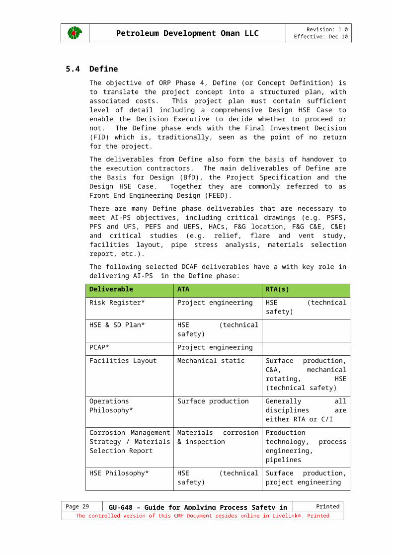
5.4 DefineThe objective of ORP Phase 4, Define (or Concept Definition) is to translate the project concept into a structured plan, with associated costs. This project plan must contain sufficient level of detail including a comprehensive Design HSE Case to enable the Decision Executive to decide whether to proceed or not. The Define phase ends with the Final Investment Decision (FID) which is, traditionally, seen as the point of no return for the project.
The deliverables from Define also form the basis of handover to the execution contractors. The main deliverables of Define are the Basis for Design (BfD), the Project Specification and the Design HSE Case. Together they are commonly referred to as Front End Engineering Design (FEED).
There are many Define phase deliverables that are necessary to meet AI-PS objectives, including critical drawings (e.g. PSFS, PFS and UFS, PEFS and UEFS, HACs, F&G location, F&G C&E, C&E) and critical studies (e.g. relief, flare and vent study, facilities layout, pipe stress analysis, materials selection report, etc.).
The following selected DCAF deliverables have a with key role in delivering AI-PS in the Define phase:
Deliverable ATA RTA(s)
Risk Register* Project engineering HSE (technical safety)
HSE & SD Plan* HSE (technical safety)
PCAP* Project engineering
Facilities Layout Mechanical static Surface production, C&A, mechanical rotating, HSE (technical safety)
Operations Philosophy* Surface production Generally all disciplines are either RTA or C/I
Corrosion Management Strategy / Materials Selection Report
Materials corrosion & inspection
Production technology, process engineering, pipelines
HSE Philosophy* HSE (technical safety) Surface production, project engineering
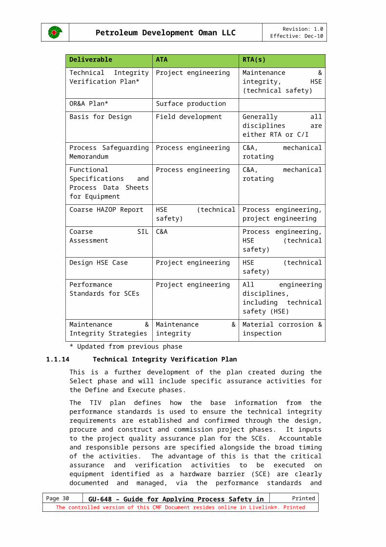
Technical Integrity Verification Plan*
Project engineering Maintenance & integrity, HSE (technical safety)
OR&A Plan* Surface production
Basis for Design Field development Generally all disciplines are either RTA or C/I
Process Safeguarding Memorandum
Process engineering C&A, mechanical rotating
Functional Specifications and Process Data Sheets for Equipment
Process engineering C&A, mechanical rotating
Coarse HAZOP Report HSE (technical safety) Process engineering, project engineering
Coarse SIL Assessment C&A Process engineering, HSE (technical safety)
Page 21 GU-648 – Guide for Applying Process Safety in Projects Printed 15/12/10
The controlled version of this CMF Document resides online in Livelink®. Printed copies are UNCONTROLLED.
Petroleum Development Oman LLC Revision: 1.0Effective: Dec-10
Deliverable ATA RTA(s)
Design HSE Case Project engineering HSE (technical safety)
Performance Standards for SCEs
Project engineering All engineering disciplines, including technical safety (HSE)
Maintenance & Integrity Strategies
Maintenance & integrity Material corrosion & inspection
* Updated from previous phase
5.4.1 Technical Integrity Verification Plan This is a further development of the plan created during the Select phase and will include specific assurance activities for the Define and Execute phases.
The TIV plan defines how the base information from the performance standards is used to ensure the technical integrity requirements are established and confirmed through the design, procure and construct and commission project phases. It inputs to the project quality assurance plan for the SCEs. Accountable and responsible persons are specified alongside the broad timing of the activities. The advantage of this is that the critical assurance and verification activities to be executed on equipment identified as a hardware barrier (SCE) are clearly documented and managed, via the performance standards and technical integrity verification plan - thus providing a fully transparent and auditable process.
Verification points are specific identifiable project phases, notably:
Preparation of Initial Performance Standards (do the performance standards contain appropriate criteria)
Equipment Design Specifications for FEED (do the specifications contain the requirements to meet the performance standards criteria)
Concept definition / FEED (does the design meet the specifications - ALARP)
Detailed Design (does the design continue to meet the specifications - ALARP)
Procurement (does the equipment to be purchased meet specs)
Procurement (does what was received meet procurement specs)
Construction (was it built per the design)
Pre-Commissioning (does it perform at the right levels)
Commissioning (does it operate at the specified performance levels)
Operating (is it meeting performance criteria when tested)
Verification may be anything from an internal peer review, to independent 3rd party, depending on assessed risk. This should be documented in the TIV Plan.
Commissioning is the ultimate Assurance and Verification point for equipment and systems prior to handover to operations. Verification provides the independence that the assurance checks and controls are adequate and robust.
5.4.2 Basis for DesignThe Basis for Design (BfD) is a compilation of project data from the Select phase and translates the field development data into a project definition. The BfD ensures that the expected project deliverables are properly captured, communicated, agreed, and acted upon. A documented BfD is critical to understand the project starting point and to enable subsequent Management of Change.
Page 22 GU-648 – Guide for Applying Process Safety in Projects Printed 15/12/10
The controlled version of this CMF Document resides online in Livelink®. Printed copies are UNCONTROLLED.
Petroleum Development Oman LLC Revision: 1.0Effective: Dec-10
5.4.3 Process Safeguarding MemorandumThe Safeguarding Memorandum, of which the Process Safeguarding Flow Scheme (PSFS) is an integral part, identifies and summarizes those protective devices (ultimate safeguards) which are installed as the ultimate level of protection against uncontrolled loss of containment of toxic and/or flammable materials. It also highlights those additional instrumented protective functions (penultimate safeguards) that provide the penultimate level of protection for a process / utility / off-plot unit against uncontrolled loss of containment.
5.4.4 Functional Specifications and Process Data Sheets for EquipmentDatasheets are typically provided for tagged equipment items and packaged units. The data must be properly captured for SAP entry. Accurate data sheet information is essential to ensure that future maintenance and production activities can be performed according to equipment manufacturer’s recommendations and industry best practices.
5.4.5 Coarse HAZOP ReportThe main HAZOP event is a formalized and systematic approach to assess process hazards and operability and takes place after the Design Review (not immediately after). It looks at the fine detail and is a check that nothing important was missed. It should be thus apparent that doing a Main HAZOP on PEFS which are not ready is an unacceptable practice that shall not be allowed. The main HAZOP report contains the completed HAZOP worksheets and marked-up master set of PEFS used in the event. The HAZOP action response forms are separate from the main HAZOP report.
5.4.6 Safety Integrity Level AssessmentThe Safety Integrity Level (SIL) assessment is the HEMP part of the Instrumented Protective Functions (IPF) classification process and incorporates a Layers of Protection Analysis (LOPA) to demonstrate that risk is reduced ALARP. The SIL determines the Safety Instrumented System (SIS) design and planned maintenance frequencies.
5.4.7 Design HSE CaseThe Design HSE Case must be developed throughout the Define phase and signed by the Project Manager at the end of the Define phase. The Design HSE Case provides the documented demonstration that HSE risks have been reduced ALARP and well as the basis for the identification of hardware Safety Critical Elements (SCEs) and Performance Standards. A key component of the Design HSE Case is the Bow-Tie diagrams for Severity Five and High Risk hazards. The Design HSE Case is the governing document that confirms that the project has looked at all aspects of AI-PS. At the end of the Define phase the project manager should sign off the Design HSE Case to meet the Design Integrity objectives of the ‘Statement of Fitness’.
SCE are derived from the Design HSE Case. The SCE Identification Report in typically an appendix of the HSE Case and provides the link between the hardware barriers identified in the Bow-Ties and the SCE identification in the Asset Register.
5.4.8 Design Performance Standards for SCE’s The Design Performance Standards must be developed during the Define phase to confirm that each selected SCE has been designed according to the relevant Shell DEPs, PDO specifications, and HEMP studies. The Design Performance Standards will mature further during the execute phase and will check that the SCEs have been constructed as designed. The existing QA/QC procedures and practices should be used to support the Design Performance Standards. The Design Performance Standards will evolve into Operate phase Performance Standards at the end of the execute phase before handover.
5.4.9 Maintenance & Integrity Strategies
Page 23 GU-648 – Guide for Applying Process Safety in Projects Printed 15/12/10
The controlled version of this CMF Document resides online in Livelink®. Printed copies are UNCONTROLLED.
Petroleum Development Oman LLC Revision: 1.0Effective: Dec-10
During the Define phase high level maintenance strategies should be determined in support of and aligned with the Operations Philosophy.
5.5 ExecuteThe Execute phase delivers the asset to the asset owner, ready for startup. The phase can last several years and includes numerous areas of very diverse expertise. All the areas of expertise will have to be integrated and managed to deliver a demonstrably safe asset.
Execute activities are primarily carried out by contractors. The challenge to PDO is to select the right method of management, contracting strategy, QA/QC and supervision of those contracts and contractors to ensure the end product is as per the customer’s requirements. Vendor and supplier activity supervision is equally critical. The customer will verify before handover that the asset is safe using the Statement of Fitness review and the Pre Start Up Audit.
There are many Execute phase deliverables that are necessary to meet AI-PS objectives, including critical drawings throughout execution (e.g. PSFS, PFS and UFS, PEFS and UEFS, HACs, F&G location, F&G C&E, C&E) and critical studies (e.g. relief, flare and vent study, facilities layout, pipe stress analysis, materials selection, etc.).
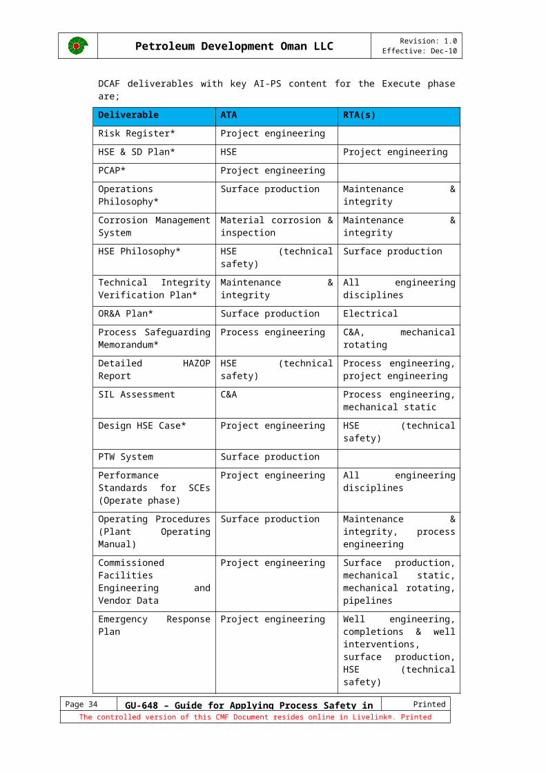
DCAF deliverables with key AI-PS content for the Execute phase are;
Deliverable ATA RTA(s)
Risk Register* Project engineering
HSE & SD Plan* HSE Project engineering
PCAP* Project engineering
Operations Philosophy* Surface production Maintenance & integrity
Corrosion Management System
Material corrosion & inspection
Maintenance & integrity
HSE Philosophy* HSE (technical safety) Surface production
Technical Integrity Verification Plan*
Maintenance & integrity All engineering disciplines
OR&A Plan* Surface production Electrical
Process Safeguarding Memorandum*
Process engineering C&A, mechanical rotating
Detailed HAZOP Report HSE (technical safety) Process engineering, project engineering
SIL Assessment C&A Process engineering, mechanical static
Design HSE Case* Project engineering HSE (technical safety)
PTW System Surface production
Performance Standards for SCEs (Operate phase)
Project engineering All engineering disciplines
Operating Procedures (Plant Operating Manual)
Surface production Maintenance & integrity, process engineering
Page 24 GU-648 – Guide for Applying Process Safety in Projects Printed 15/12/10
The controlled version of this CMF Document resides online in Livelink®. Printed copies are UNCONTROLLED.

Petroleum Development Oman LLC Revision: 1.0Effective: Dec-10
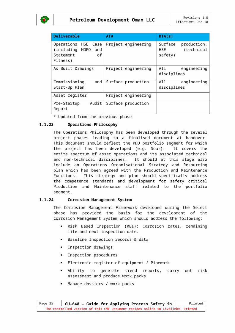
Deliverable ATA RTA(s)
Commissioned Facilities Engineering and Vendor Data
Project engineering Surface production, mechanical static, mechanical rotating, pipelines
Emergency Response Plan Project engineering Well engineering, completions & well interventions, surface production, HSE (technical safety)
Operations HSE Case (including MOPO and Statement of Fitness)
Project engineering Surface production, HSE (technical safety)
As Built Drawings Project engineering All engineering disciplines
Commissioning and Start-Up Plan
Surface production All engineering disciplines
Asset register Project engineering
Pre-Startup Audit Report Surface production
* Updated from the previous phase
5.5.1 Operations PhilosophyThe Operations Philosophy has been developed through the several project phases leading to a finalised document at handover. This document should reflect the PDO portfolio segment for which the project has been developed (e.g. Sour). It covers the entire spectrum of asset operations and its associated technical and non-technical disciplines. It should at this stage also include an Operations Organisational Strategy and Resourcing plan which has been agreed with the Production and Maintenance Functions. This strategy and plan should specifically address the competence standards and development for safety critical Production and Maintenance staff related to the portfolio segment.
5.5.2 Corrosion Management SystemThe Corrosion Management Framework developed during the Select phase has provided the basis for the development of the Corrosion Management System which should address the following:
Risk Based Inspection (RBI): Corrosion rates, remaining life and next inspection date.
Baseline Inspection records & data
Inspection drawings
Inspection procedures
Electronic register of equipment / Pipework
Ability to generate trend reports, carry out risk assessment and produce work packs
Manage dossiers / work packs
Page 25 GU-648 – Guide for Applying Process Safety in Projects Printed 15/12/10
The controlled version of this CMF Document resides online in Livelink®. Printed copies are UNCONTROLLED.
Petroleum Development Oman LLC Revision: 1.0Effective: Dec-10
5.5.3 Technical Integrity Verification Report At the end of the Execute phase, a TIV report is required capturing the following:
TIV Plan compliance.
Safety Critical Element (SCE) Identification Report, documenting the SCE selection process which involves the analysis of risk.
Design Performance Standards for the SCEs, describing performance criteria, covering functionality, availability, reliability and interdependency. The performance criteria are set such that compliance with them will mean that the risks of the occurrence of MAEs during the Operate phase are reduced to ALARP.
Records available of the verification tasks carried out, including commissioning and any outstanding actions.
5.5.4 Safety Integrity Level AssessmentDuring detailed engineering, the IPF classification process is applied to all IPFs as not all IPFs are analysed during the Define phase and revisits IPFs already analysed during FEED, for instance in case the process design has changed.
5.5.5 Permit to Work An Permit to Work (PTW) system approved by PDO, and in accordance with PR-1172 Permit to Work System should be in place.
5.5.6 Operate Phase Performance Standards for SCE’sThe Operate phase Performance Standards for SCE’s should evolve from the Design Performance Standards. These Performance Standards are formatted to comply with the requirements of SAP-PM and SAP-QM in terms of minimum assurance tasks, assurance measures, assurance value and units of measure for the correct allocation to the appropriate level in the asset hierarchy.
5.5.7 Plant Operating Procedures Operating Procedures and Manuals should be in place for all equipment including training. The Operators should be trained in the use and of the Operating Procedures before commissioning.
5.5.8 Emergency Response PlanThe ER Plan should be in place covering representative process safety incident scenarios developed from the HSE Case. For critical high risk sour facilities, these should include Sour Hydrocarbon Contingency Plans. For facilities with large flammable inventories, the plan should include Pre-Fire Planning.
5.5.9 Operations HSE CaseAt the end of detailed design, the Design HSE Case should be finalised and demonstrate Design Integrity. The Project Manager should sign the Design HSE Case thereby confirming that the detailed design will result in ALARP AI-PS risk levels. The Design HSE Case is then subsequently further matured into the Operations HSE Case in the standard PDO format. The Operations HSE Case includes the HSE Critical Positions and Tasks required to support AI-PS management. Commissioning activities and SIMOPS during construction will require separate addendums to the Operations HSE Case.
Page 26 GU-648 – Guide for Applying Process Safety in Projects Printed 15/12/10
The controlled version of this CMF Document resides online in Livelink®. Printed copies are UNCONTROLLED.
Petroleum Development Oman LLC Revision: 1.0Effective: Dec-10
Manual of Permitted OperationsPart of the Operations HSE Case is the Manual of Permitted Operations (MOPO), which is an information tool to assist Supervisors and Line Managers during the planning and coordination of operations and activities by providing useful information on:
The operating envelope and safe operating limits
Actions to take if or when certain situations arise that could compromise safe operating limits. These situations are identified from:
o The Threats and Escalation Factors identified as part of the Bow-Tie assessments for the RAM 5 Hazards
o An assessment of other operations and activities that could contribute to the escalation of an incident (e.g. continuing with hot work when fire pumps are unavailable).
Statement of FitnessThe Statement of Fitness is an integral part of the Operations HSE Case and by signing the Statement of Fitness the new asset owner agrees that:
Process safety risks have been identified and documented in the HSE Cases and are managed to ALARP;
Employees or contractors executing HSE Critical Activities identified in the Operations HSE Case are competent and fit to work;
Safety Critical Equipment (SCE) meets its Design Performance Standards;
Design and construction of the facility meet the design and engineering requirements, i.e. as a minimum compliance with the SHALL [PS] requirements in PDO specifications and Shell DEPs; the Process Safety Basic Requirements are met; and AI-PS project actions are closed or have risk-assessed plans for closure;
As-built drawings, documentation and data pertinent to maintaining AI-PS are provided.
Procedures are in place to operate SCE within its Operational Limits.
The Statement of Fitness should be signed prior to the Pre-Startup Audit (PSUA), which is the last official technical review of the suitability of a facility to accept hydrocarbons.
5.5.10 Critical Documents and DrawingsThe critical drawings available at project handover will be the "'Red Lined"" marked up drawings, not the normal As Built drawings, as producing As Built drawings and uploading them into Livelink can take several months after commissioning. Typical critical drawings are Hazardous area plot drawings, PEFS's and Cause and Effect drawings. An example of a critical document is the Equipment Vendor Operations and Maintenance manual.
5.5.11 Commissioning and Start-Up (CSU) PlanA detailed CSU execution plan and related CSU deliverables are developed for each hardware delivery group to support the execution of CSU requirements during the Execute and Startup phase. The Level 4 (including resources) CSU execution plans are aligned with construction plans to create an integrated Mechanical Completion/ CSU plan (Completions Milestones) that includes all hold/ witness points, including certifying/ verification authorities to verify Technical Integrity of the procured and built equipment.
Page 27 GU-648 – Guide for Applying Process Safety in Projects Printed 15/12/10
The controlled version of this CMF Document resides online in Livelink®. Printed copies are UNCONTROLLED.

Petroleum Development Oman LLC Revision: 1.0Effective: Dec-10
Startup procedures, inclusive of coarse “Startup on paper” exercises are critical due to the number of historical process safety incidents during facility or equipment startup.
Page 28 GU-648 – Guide for Applying Process Safety in Projects Printed 15/12/10
The controlled version of this CMF Document resides online in Livelink®. Printed copies are UNCONTROLLED.
Petroleum Development Oman LLC Revision: 1.0Effective: Dec-10
5.5.12 Asset RegisterThe data in the asset register must be complete and accurate since this data is the starting point of all maintenance related activities. Particularly Technical Integrity demonstration is not possible if the Asset Register is incomplete or the data is inaccurate. We must be able to measure the performance of all our SCEs at regular intervals.
The Project shall develop a database of tagged items in accordance with the Asset breakdown tagging procedure. The Safety Critical Elements (SCEs) must be properly identified, as per the SCE manual.
5.5.13 Pre-Startup AuditThe project must go through a Pre-Startup Audit (PSUA). This audit will cover all aspects of the project and is considered the last check point before the introduction of Hydrocarbons into the facility. This audit will also review the status of action items generated from the HEMP and the Operations HSE Case. The facility may be started after all critical action items have been completed.
5.5.14 Non-DCAF Deliverables
Computerised Maintenance Management SystemA Computerised Maintenance Management System (CMMS) is used to manage the maintenance activities of equipment. It includes the following:
Asset register and equipment characteristics by Functional location and Tag number.
Functional hierarchies and SAP class data
System and equipment criticality assessment
Operations Performance Standards for identified Safety Critical Elements
Maintenance & Inspection task lists
Spare parts interchangeability record (E-SPIR)
Bills of material for selected equipment (BOM)
Facility Status ReportFacility Status Report (FSR) provides 3 main functions:
Visualisation of the SAP work order and notification status by barrier or SCE group at any level within the asset hierarchy.
Flag and monitor those work orders and notifications that require action.
Auditable electronic Deviation Management System.
FSR should be live at commissioning and showing ‘green’ for all the SCEs indicating they have passed their first performance test (i.e. commissioning) successfully.
Page 29 GU-648 – Guide for Applying Process Safety in Projects Printed 15/12/10
The controlled version of this CMF Document resides online in Livelink®. Printed copies are UNCONTROLLED.
Petroleum Development Oman LLC Revision: 1.0Effective: Dec-10
Operating Envelopes and Alarm ManualThe operating envelopes and alarm catalogue, should be further developed, reviewed and endorsed based on the ESP process. This will evolve into the Trip and Alarm management deliverable in the Execute phase of the project.
The Operating envelope illustrates the integrity and capacity constraints of a system, piece of equipment (e.g. separator, dehydration tank, compressor, etc.), well, pipeline or a production station. For rotating equipment, this will include the operating curves. It is recommended that the high level operating envelope is further broken down to lower level details e.g.
Asset Level Envelopes
System Level Envelopes
Specific Equipment Envelopes
The relevant technical authority, e.g. process, rotating, static engineer sets the limits for equipment and facilities and the Production Technologists sets the envelope for the wells. These operating envelopes must be clearly communicated to Operations staff prior to facility handover.
Trip & Alarm ManagementMajor process safety disasters over the last decades have shown that lack of operator empowerment to take independent actions can lead to extreme consequences. Human inhibitions or hesitations, that are usually culture dependent, may override human capability. This has led to not taking action at all, often against better judgment. To deal with the situation as described above, a simple philosophy for setting operating limits and designing or restructuring notification systems has been adopted and summarised below:
Know the (safe) process limits on which the notifications are based. These limits must be demonstrably and verifiably within the engineering constraints of equipment. To ensure consistency, all constraints and limits should reside in a single, electronic repository;
Limits should be made visible to the operator in a non-numerical format, e.g. as trends, to enable the operator's situational awareness;
Limit exceedance notifications (Alarms and alerts) should be simple and uniform, whilst rigorously eliminating anything that is unnecessary. In particular, no notifications should exist for desired events, e.g. if equipment is intentionally switched off or is out of operation;
Actions necessary to bring the process back to its normal state shall be predefined for every limit and shall be available to the operator. The operator shall be formally empowered to execute such actions.
An automated system should monitor and report the performance of the notification system (alarm system) and its interactions with the operator.
Inhibit ManagementAn Inhibit Management System should be in place at handover to manage the new facility operation. This should be controlled and documented via operating procedures in POM's and also by MoC when inhibits or overrides are in place for extended periods. Approval levels should be stated and personnel responsible informed.
Page 30 GU-648 – Guide for Applying Process Safety in Projects Printed 15/12/10
The controlled version of this CMF Document resides online in Livelink®. Printed copies are UNCONTROLLED.
Petroleum Development Oman LLC Revision: 1.0Effective: Dec-10
Key Registers Key Registers must be in place, auditable and up to date. Typical Key Registers are competence, inhibits, temporary repairs, deviations, etc.
Operations HandoversA robust and structured handover process between key Process Safety critical positions must be in place for both daily and shift (tour) handovers. LINK
Page 31 GU-648 – Guide for Applying Process Safety in Projects Printed 15/12/10
The controlled version of this CMF Document resides online in Livelink®. Printed copies are UNCONTROLLED.
Petroleum Development Oman LLC Revision: 1.0Effective: Dec-10
6 Process Safety Basic RequirementsProcess Safety Basic Requirements (PSBR) are requirements derived from learning from past AI-PS accidents in the industry. All PSBRs are covered by various DEPs and SPs, Procedures and Codes of Practice. Therefore compliance with these documents will ensure that all PSBR requirements are met by default. However every project must be able to demonstrate through the HSE Case that the relevant PSBRs are specifically met before the introduction of hydrocarbons.
The relevant PSBR elements are:
Safe sighting of portable and permanent buildings, in accordance with SP-1127.
Permit to work, in accordance with PR-1172 – Permit to Work System.
Management of change process is in place and subject to level 2 and level 3 assurance.
Avoid liquid release relief to atmosphere, i.e. create an inventory of all atmospheric vents that have the potential to release hydrocarbon liquid above its flash point, assess the risk of each of these vents and define the risk mitigation.
Avoid tank overfill followed by vapour cloud release, i.e. create an inventory of all storage tanks containing fluids that have the potential to overfill resulting in a vapour cloud explosion. Examples of such fluids are natural gas liquids (condensates) and crude oils with a Reid Vapour Pressure (RVP) > 2.5 psi. Assess the risk of each tank and define the risk mitigation.
Avoid brittle fracture of metallic materials, i.e. determine the LDT or MAT for all process equipment and piping, containing liquefied gas or compressed flammable low molecular weight hydrocarbon gas. Take measures to prevent the equipment being at pressure below the LDT or alternatively ensure the equipment metal temperature is not below the appropriate MAT at any given operating pressure. Consider scenarios in which equipment temperature can drop such as blow-downs, as well as scenarios of subsequent (re-)pressurization of equipment.
Alarm management, to meet the requirements of DEP 32.80.10.14 using a methodology such as ESP.
Sour gas (H2S), in accordance with SP-1190 – Design for Sour Service Specification and PR-1078 – H2S Management.
Page 32 GU-648 – Guide for Applying Process Safety in Projects Printed 15/12/10
The controlled version of this CMF Document resides online in Livelink®. Printed copies are UNCONTROLLED.

Petroleum Development Oman LLC Revision: 1.0Effective: Dec-10
Appendix 1 – Reference MaterialThe following reference material relates to AI-PSM:
1. HSE & SD Policy - The Asset Integrity-Process Safety Policy is an integral part of PDO’s HSE & SD policy
2. Opportunity Realisation Process / ORP Navigator - The Opportunity Realisation Process (ORP) defines project delivery through each phase of the project - Identify, Assess, Select, Define, Execute and Operate and addresses the governance and assurance processes to be applied at each phase before proceeding to the next. It is important to note that the ORP is a framework. There are a number of mandatory stages and events, but the depth and degree of activity undertaken at each phase will depend on the nature of the project, its size, cost and associated risks. In this way, the process, and particularly its project assurance elements, are scalable. This document is a part of the ORP
3. Design Controls and Assurance Framework (DCAF) - DCAF standardises the framework in which Quality Control (QC) and Quality Assurance (QA) of discipline decisions and deliverables is conducted. DCAF is applicable across all disciplines and all ORP phases.
DCAF will ensure that each discipline has a standard, which lists the decisions and deliverables the discipline contributes to each phase of the Opportunity Realisation Process (ORP), plus the required authority level for sign off. DCAF delegates the authority to take discipline decisions, or signing off discipline deliverables, to qualified individuals in a rigorous and auditable manner. It consists of 4 standards
Discipline Standards: Standards (global and local) that lists all discipline decisions and deliverables that need sign off by an authorized individual;
Discipline Authority Manual: A lists of individuals with their authority levels;
Project/Asset Controls and Assurance Plan: A plan of what needs to be controlled/assured per ORP phase;
Project/Asset Controls and Assurance Schedule: A schedule of QC/QA activities for a project or asset.
4. Health, Safety and Environment Management System CP-122 - The HSE Management System details the basic requirements for implementing AI-PS requirements throughout the Company.
5. Project Engineering Code of Practice CP-117 - The Project Engineering Code of Practice details practices to be followed while developing and delivering projects as a part of Opportunity Realisation Process. The document also highlights the mandatory requirements at various project phases.
6. Operations Readiness and Assurance PR-1612 - The Operations Readiness and Assurance procedure describes what to do in order to achieve flawless start up of the project. Demonstrable AI-PS is an integral part of OR&A
7. Maintenance and Integrity Management Code of Practice CP-114 - The Maintenance and Integrity Code of Practice details practices to asset and project teams which ensure a common approach to Maintenance and Integrity Management. It contains useful links to (Shell) Maintenance and Integrity related procedures, process guides etc
Page 33 GU-648 – Guide for Applying Process Safety in Projects Printed 15/12/10
The controlled version of this CMF Document resides online in Livelink®. Printed copies are UNCONTROLLED.
Petroleum Development Oman LLC Revision: 1.0Effective: Dec-10
8. Operate Product Surface Flow Assets CP-115 - This Code of Practice defines the Strategies and Controls that need to be implemented in PDO for the effective Operation of Surface Product Flow Assets. It makes reference to Shell Standards and Processes when they are applicable and where there is no equivalent available within PDO
9. Specification for HSE Cases SP-2062 – This Specification establishes the minimum requirements for the content of Preliminary Design, Design and Operations HSE Cases. The Specification contains information on the contents of each type of HSE Case and gives guidance and examples of information to be contained in specific sections.
10. Commissioning and Start-Up PR-1159 - The purpose of this procedure is enable Projects, Contractors and Operations personnel to adopt a uniform approach to the preparation, organisation and execution of commissioning and Startup activities on their projects. This will assist in achieving consistency of approach to definition, division of responsibilities and execution across all projects.
It references the relevant Operational Readiness and Assurance (OR&A) processes and comprises a collection of best practice processes, procedures and guidelines, the application of which will assist project teams in realising the value of the opportunity.
Page 34 GU-648 – Guide for Applying Process Safety in Projects Printed 15/12/10
The controlled version of this CMF Document resides online in Livelink®. Printed copies are UNCONTROLLED.
Petroleum Development Oman LLC Revision: 1.0Effective: Dec-10
Appendix 2 – AbbreviationsAI-PS Asset Integrity - Process Safety
ALARP As Low As Reasonably Practicable
BfD Basis for Design
BOM Bills of material for selected equipment
DCAF Discipline Control and Assurance Framework
DE
DEP Design Engineering Procedure
DRB Decision Review Board
ESP Ensure Safe Production
ESP Ensure Safe Production
E-SPIR Spare parts interchangeability record
FEED Front End Engineering and Design
FERM Fire Explosion and Risk Management
FSR Facility Status Report
HAZID Hazard Identification
HEMP Hazard and Effects Management Process
MAE
MoC Management of Change
MOPO Matrix of Permitted Operations
OR&A Operations Readiness & Assurance
ORM
ORP Opportunity Realization Process
PCAP Project Controls and Assurance Plan
PEFS Process Engineering Flow Schematic
POM Plant Operating Manual
PTW Permit to Work
QA Quality Assurance
QC Quality Control
RAM Risk Assurance Matrix
RBI Risk Based Inspection
SCE Safety Critical Element
SIL Safety Integrity Level
SoF Statement of Fitness
SP Specification
TIV Technical Integrity Verification
VAR Value Assurance Review
Page 35 GU-648 – Guide for Applying Process Safety in Projects Printed 15/12/10
The controlled version of this CMF Document resides online in Livelink®. Printed copies are UNCONTROLLED.
Petroleum Development Oman LLC Revision: 1.0Effective: Dec-10
Appendix 3 – End of Delivery Map (to be developed)
Page 36 GU-648 – Guide for Applying Process Safety in Projects Printed 15/12/10
The controlled version of this CMF Document resides online in Livelink®. Printed copies are UNCONTROLLED.