GUIDANCE PAPER VELUX MODULAR SKYLIGHTS SELF …/media/vms/brochure-and... · 2019-09-24 · Version...
22
Version 04 - 14.01.2019 1 /22 www.velux.com GUIDANCE PAPER VELUX MODULAR SKYLIGHTS SELF-SUPPORTING RIDGELIGHT Determination of structural design values 1. Introduction The aim of this document – together with ETA 17/0467 of 2019-01-28 is to provide guidance to the determination of design values. ETA-17/0467 contains information on the kit, e.g. the structural system, hardware, cross section of the profiles, as well as the characteristic values. For convenience, a number of the relevant characteristic values are repeated in this document. By means of structural calculations and design values, it can be demonstrated whether the requirements of the load bearing capacity of a specific kit, installed in a given building on a given location, are met. The calculations should be carried out by a competent body. The examples in this document demonstrate how the calculations could be carried out. National Standards and Annexes may specify different loads and combinations hereof, that are not mentioned in this document. The load bearing capacity of the glazing is not subject to this document. 2. Principle The design load bearing capacities (1) Rd and Cd shall be calculated using the following equations (see ETAG 010, 6.3.1.1 and 6.3.1.2): Rd = Rk/(ɣMR*Kt*Ku*Kθ) and Cd = Ck/(ɣ MC *Ct*Cu*Cθ) where: Rk = Characteristic load bearing capacity (ULS) calculated in accordance with ETA- 17/0467 Ck = Characteristic load bearing capacity (SLS) calculated in accordance with ETA- 17/0467 ɣMR = partial safety factor for ULS ɣMC = partial safety factor for SLS Kt = effect of duration for ULS (2) Ct = effect of duration for SLS (2) Ku = effect of ageing/environment for ULS (2)
Transcript of GUIDANCE PAPER VELUX MODULAR SKYLIGHTS SELF …/media/vms/brochure-and... · 2019-09-24 · Version...

Version 04 - 14.01.2019
1 /22
www.velux.com
GUIDANCE PAPER VELUX MODULAR SKYLIGHTS SELF-SUPPORTING RIDGELIGHT Determination of structural design values
1. Introduction The aim of this document – together with ETA 17/0467 of 2019-01-28 is to provide guidance to the determination of design values. ETA-17/0467 contains information on the kit, e.g. the structural system, hardware, cross section of the profiles, as well as the characteristic values. For convenience, a number of the relevant characteristic values are repeated in this document. By means of structural calculations and design values, it can be demonstrated whether the requirements of the load bearing capacity of a specific kit, installed in a given building on a given location, are met. The calculations should be carried out by a competent body. The examples in this document demonstrate how the calculations could be carried out. National Standards and Annexes may specify different loads and combinations hereof, that are not mentioned in this document. The load bearing capacity of the glazing is not subject to this document. 2. Principle
The design load bearing capacities (1) Rd and Cd shall be calculated using the following equations (see ETAG 010, 6.3.1.1 and 6.3.1.2):
Rd = Rk/(ɣMR*Kt*Ku*Kθ) and
Cd = Ck/(ɣMC*Ct*Cu*Cθ)
where:
Rk = Characteristic load bearing capacity (ULS) calculated in accordance with ETA-17/0467 Ck = Characteristic load bearing capacity (SLS) calculated in accordance with ETA-17/0467 ɣMR = partial safety factor for ULS ɣMC = partial safety factor for SLS Kt = effect of duration for ULS (2) Ct = effect of duration for SLS (2) Ku = effect of ageing/environment for ULS (2)

Version 04 - 14.01.2019
2 /22
www.velux.com
Cu = effect of ageing/environment for SLS (2) Kθ = effect of temperature for ULS (2) Cθ = effect of temperature for SLS (2)
Notes: (1) The self-weight, including partial safety factors, shall be calculated in accordance with Clause 6. (2) Relevant only for profiles and hardware connections connected to the profiles.
3. Partial safety factors, magnification and reduction factors Whenever possible internationally and/or nationally determined parameters and factors shall be taken into account. By default, the parameters and factors shown in Table 1 and Table 2 and Table 5 are recommended. The recommended parameters are based on: “BÜV-Empfehlung Tragende Kunststoffbauteile im Bauwesen [TKB] - Entwurf, Bemessung und Konstruktion - Stand 08 / 2010” (BÜV) and some European standards and VELUX test reports. Table 1: Partial safety factors
Notes:
(1) See BÜV Tablelle E-1 (2) See EN 1993-1-8:2005, section 2.2 (3) See BÜV Abschnitt 5.5
Table 2: Magnification and reduction factors (8)
ULS SLS
Kt (1) (2)
10 minutes 1,10 Ct
(1) (4)
10 minutes 1,02
1 week 1,48 1 week 1,08 3 weeks 1,55 3 weeks 1,09 1 month 1,58 1 month 1,10 3 months 1,66 3 months 1,11 6 months 1,71 6 months 1,11 25 years 2,02 25 years 1,15
Ku (1) (3) 1,2 Cu (1) (5) 1,2
Kθ (1) 0°C (6) 0,95 Cθ (1) 0°C (6) 1,00 20°C (6) 1,00 20°C (6) 1,00 40°C (7) 1,35 40°C (7) 1,05 60°C (6) 1,50 60°C (6) 1,05 80°C (6) 2,05 80°C (6) 1,10
Partial safety factor ɣMR ɣMC
Frame profiles at connections 1,5 (1) Not relevant
Bolt/Rivet/Bracket/Rotating shoe/Mounting clamp 1,25 (2) Not relevant
Frame profiles 1,2 (1) 1,1 (3)

Version 04 - 14.01.2019
3 /22
www.velux.com
Notes: (1) Kt = A
f
1
, Ct = A
E
1 (see ETAG 010: 2002, section 6.3 and Annex H, BÜV Abschnitt 5.2)
Ku = Af
2
, Cu = A
E
2 (see ETAG 010: 2002, section 6.3 and Annex H, BÜV Abschnitt 5.2)
Kθ = Af
3
, Cθ = A
E
3 (see ETAG 010: 2002, section 6.3 and Annex H, BÜV Abschnitt 5.2)
(2) See BÜV Tabelle B-1a and Gleichung 8.2. (3) See BÜV Tabelle B-2. (4) See BÜV Tabelle B-1b and Gleichung 8.2. (5) See BÜV Tabelle B-2. (6) See VELUX test reports no. 147775 and 145611 and DTI report no. 743795-2. (7) Conservative approximation based on measurements from VELUX test reports nos. 147775 and 145611. (8) Relevant only for profiles and their hardware connections.
4. Design values of small scale tests
The design values of the small-scale tests can be calculated as shown in Table 3. Table 3: Characteristic and design values
Property Characteristic values see ETA-17/0467 Annex D.1
Design values see Table 1 and Table 2 above
Tensile strength 832,9 MPa ULS= Characteristic value / (ɣMR *Kt*Ku*Kθ) SLS= Characteristic value / (ɣMC*Ct*Cu*Cθ)
Compression strength 465 MPa
Bending strength 1257 MPa
E-modulus 39,5 GPa
41,6 GPa (1)(3)
G-modulus 3,1 GPa
3,4 GPa (2)
Shear strength 53,8 MPa Notes:
(1) Mean value, confidence level 75%, unknown standard deviation (See ISO 16269-6:2014). (2) Mean value, confidence level 75%, unknown standard deviation (See ISO 16269-6:2014). (3) For openable windows subjected to a downward action force, the E-modulus shall be multiplied with a factor of 0,83, see “VELUX
report 1100005818_06_1 VMS Full scale test Ridgelight – Stiffness of module 2016-11-29”

Version 04 - 14.01.2019
4 /22
www.velux.com
5. Determination of values for hardware connections Figure 1: Applied forces to the hardware

Version 04 - 14.01.2019
5 /22
www.velux.com
Table 4: Characteristic and design values for hardware connections Element/Connection Characteristic value Rk [kN] Design value Rd [kN]
see Table 1
A Top bolt connection (calculated minimum) 13,5 (1) ULS= Characteristic value / ɣMR SLS: Not relevant
B Bottom bolt connection (calculated minimum) 17,6 (1) G Rotating shoe/mounting clamp/roof connection in 90° 20,3 H Rotating shoe/mounting clamp/roof connection in 180° 28,2
Note: (1) Strength of the bottom and top bolt themselves: 17,6 kN
Element/Connection
Characteristic Value Rk [kN] (1) Product variant
HFC 100240 0010B
HVC 100240 0010B
HFC 100240 0016TB
HVC 100240 0016TB
C Top corner bracket/frame connection in 0° 8,5 11,2 9,0 10,9 D Bottom corner bracket/frame connection in 0° 11,9 11,9 10,9 12,4 E Bottom corner bracket/frame connection in 180° 8,5 11,2 9,0 10,9 F Bottom corner bracket/frame connection in 270° 3,9 2,0 4,3 2,1 J Top corner bracket/frame connection in 270° 3,9 2,0 4,3 2,1 K Top corner bracket/frame connection in 180° 11,9 11,9 10,9 12,4 L Top corner bracket/frame connection in 315° 6,2 3,4 6,0 3,5 M Bottom corner bracket/frame connection in 225° 6,2 3,4 6,0 3,5 N Bottom corner bracket/frame connection in 90° 6,0 6,0 6,2 5,7 P Top corner bracket/frame connection in 90° 6,0 6,0 6,2 5,7 Q Bottom corner bracket/frame connection in 315° 5,4 3,0 5,0 3,6 R Top corner bracket/frame connection in 225° 5,4 3,0 5,0 3,6 S Bottom corner bracket/frame connection in 135° 7,8 8,2 8,1 7,5 T Top corner bracket/frame connection in 45° 7,8 8,2 8,1 7,5 U Top corner bracket/frame connection in 135° 8,6 9,3 8,6 9,0 W Bottom corner bracket/frame connection in 45° 8,6 9,3 8,6 9,0 DW Bottom corner bracket/frame connection in 18° 13,8 16,8 13,3 17,1 UK Top corner bracket/frame connection in 162° 13,8 16,8 13,3 17,1 QD Bottom corner bracket/frame connection in 342° 10,0 6,4 10,2 6,1 KR Top corner bracket/frame connection in 198° 10,0 6,4 10,2 6,1
Note: (1) Without influence caused by nationally determined magnification and reduction factors (duration, aging/environment, temperature, i.e.
Ct = Cu = CQ = 1 and Kt = Ku = KQ = 1, see ETAG 010, 6.3.1.2)

Version 04 - 14.01.2019
6 /22
www.velux.com
Figure 2: Determination of values for hardware connections in other directions than tested (principle)
Version 04 - 14.01.2019
7 /22
www.velux.com
6. Self-weight The self-weight (including hardware, lining, cladding and flashing) of the fixed roof window (Gf and gf) and the openable roof window (Gv and gv) shall be calculated as follows:
Gf = (W-12) * (L-96) * t*25*10-9+2(W+L) *57*10-6 [kN] gf = Gf /(W*L)* 106 [kN/m2] and Gv = (W-12) * (L-96) * t*25 * 10-9+2(W+L) * 96 * 10-6 [kN] gv = Gv /(W*L)* 106 [kN/m2] where: W = Width of the roof window in mm L = Height of the roof window in mm t = Sum of glass thicknesses in mm Table 5: Partial safety factors for permanent action (self-weight):
7. Load combinations According to BÜV Abschnitt 8.2 the load combinations can be divided up into 3 load durations.
1. Long term, only self-weight 2. Medium term, self-weight and snow load 3. Short term, self-weight, snow load and wind load
In medium term, only the snow load is set as dominate load regarding the load combinations from EN 1990:2007 In short term respectively snow and wind load is set as the dominate load. 8. Load bearing capacity for wind suction For an openable window subjected to a perpendicular upward force the connection between the casement and frame profile is to be investigated. The load bearing capacity is found in VELUX report: “11000008316_30_0 VMW Suction on venting Frames” dated 2017-12-08 and shown in Table 6. Table 6: Characteristic load bearing capacity for openable windows between casement and frame profile, for a suction force perpendicular to the window frame
Load bearing capacity Double glazing 8,87 kN Triple glazing 8,72 kN
Unfavourable Favourable Unfavourable Reference ɣG,sup ɣG,inf ξG,sup
ULS 1,35 1,0 0,85 EN 1990:2007, Table A1.2(B), Eq. 6.10b
SLS 1,0 1,0 N/A EN 1990:2007, Table A1.4

Version 04 - 14.01.2019
8 /22
www.velux.com
9. Examples of design values for the load bearing capacity Table 7a: Characteristic and design load bearing capacities for snow-load
Characteristic values for s see ETA-17/0467 Annex E.1
Design calculation Self-weight partial safety factors (see Table 5): γG,sup,ULS=1,35 ξG,sup,ULS=0,85 γG,sup,SLS=1,00 Material partial safety factors (see Table 1): γMR,ULS=1,50 γMC,SLS=1,10 Magnification and reduction factors (see Table 2): Medium term - snow load (1): 3 months duration, 20°C. Kt=1,66; Ku=1,2; Kθ=1,00 Ct=1,11; Cu=1,2; Cθ=1,00 Load factor snow, from EN 1990:2007: ɣQ,1 = 1,5 E- modulus: E= 0,83 x 41,6 GPa See Note 3 to Table 3.
Application examples – Snow-load α° ULS
[kN/m2]
SLS [kN/m2] ULS (2)
[kN/m2]
SLS (3) [kN/m2]
1/300 1/150 1/300 1/150
25° 9,0 1,5 3,8 2,33 0,53 1,81
30° 10,6 1,6 4,0 2,84 0,59 1,93
35° 12,0 1,7 4,2 3,31 0,67 2,08
40° 13,7 1,9 4,6 3,81 0,76 2,27
Notes: (1) Load combination ULS: 𝛾𝛾𝐺𝐺,𝑠𝑠𝑠𝑠𝑠𝑠 ∙ 𝜉𝜉𝐺𝐺,𝑠𝑠𝑠𝑠𝑠𝑠 ∙ 𝐺𝐺𝑘𝑘 + 𝛾𝛾𝑄𝑄,1 ∙ 𝑠𝑠𝑘𝑘 SLS: 𝐺𝐺𝑘𝑘 + 𝑠𝑠𝑘𝑘 (2) Values in Table are design snow load for ULS: 𝛾𝛾𝑄𝑄,1 ∙ 𝑠𝑠𝑘𝑘 (3) Values in Table are design snow load for SLS: 𝑠𝑠𝑘𝑘
Type: 2x HVC100240 0016T (1000mm x 2400mm) Glazing: 22 mm glass in total

Version 04 - 14.01.2019
9 /22
www.velux.com
Table 7b: Characteristic and design load bearing capacities for wind suction
Characteristic values for qs see ETA-17/0467 Annex E.1
Design values Self-weight partial safety factors (see Table 5): γG,inf,ULS=1,00 γG,sup,SLS=1,00 Material partial safety factors (see Table 1): γMR,ULS=1,50 γMC,SLS=1,10 Magnification and reduction factors (see Table 2): Short term - wind load (2): 10 minutes, 60°C (1). ULS: Kt=1,10; Ku=1,2; Kθ=1,50 SLS: Ct=1,02; Cu=1,2; Cθ=1,05 Load factor wind, from EN 1990:2007: ɣQ,1 = 1,5
Application examples – Wind suction α° ULS
[kN/m2]
SLS [kN/m2] ULS (3)
[kN/m2]
SLS (4) [kN/m2]
1/300 1/150 1/300 1/150
25° 5,0 1,9 3,4 2,01 (5) 1,53 2,53
30° 5,1 1,9 3,3 2,05 (5) 1,51 2,51
35° 5,0 1,9 3,3 1,77 (5) 1,48 2,48
40° 4,4 1,9 3,3 1,79 (5) 1,45 2,45
Notes:
(1) See VELUX test report 149292. (2) Load combination ULS: 𝛾𝛾𝐺𝐺,𝑖𝑖𝑖𝑖𝑖𝑖 ∙ 𝐺𝐺𝑘𝑘 + 𝛾𝛾𝑄𝑄,1 ∙ 𝑞𝑞𝑠𝑠,𝑘𝑘 SLS: 𝐺𝐺𝑘𝑘 + 𝑞𝑞𝑠𝑠,𝑘𝑘 (3) Values in Table are design snow load for ULS: 𝛾𝛾𝑄𝑄,1 ∙ 𝑞𝑞𝑠𝑠,𝑘𝑘 (4) Values in Table are design snow load for SLS: 𝑞𝑞𝑠𝑠,𝑘𝑘 (5) Failure between casement and frame profile, see Clause 8
Type: 2x HVC100240 0010 (1000mm x 2400mm) Glazing: 14 mm glass in total

Version 04 - 14.01.2019
10 /22
www.velux.com
10. Calculation example, asymmetric load (design values) For the calculations example “Asymmetric load” the same example as Annex E.2 in ETA-17/0467 is used. To demonstrate the calculation procedure, a VELUX modular skylight self-supporting ridgelight application under asymmetric wind and snow load is examined. Geometry and roof window variant is the same as in the wind load example in Table 7b: 2 x HVC1002400 0010 (1000mm x 2400mm). Glazing: 14mm glass in total. The pitch is α = 25°. Figure 3: Load model for calculation example
Partial safety factors and the magnification and reduction factors used in the calculation are presented in Tables 8a and 8b. Table 8a: Partial safety factors
ULS SLS Frame profiles at connections: ɣMR = 1,5 N/A Frame profiles: ɣMR = 1,2 ɣMC = 1,1 Variable Load, leading: ɣQ,1 = 1,5 (1) ɣQ,1 = 1,0 (1) Variable Load, non-leading: ɣQ,i = 1,5 (1) ɣQ,i = 1,0 (1) Permanent action, unfavourable: ɣG,sup = 1,35 ɣG,sup = 1,0 Permanent action, favourable: ɣG,inf = 1,0 ɣG,inf = 1,0 Factor for combination, wind Ψ 0,wind = 0,6 (1) Ψ 0,wind = 0,6 (1) Factor for combination, snow Ψ 0,snow = 0,5 (1) Ψ 0,snow = 0,5 (1) Reduction factor for Gsup ξG,sup = 0,85 N/A
Note: (1) See EN 1990:2007 Table 8b: Magnification and reduction factors
ULS SLS Duration dependency, self-weight leading: Kt,25 years = 2,02 Ct,25 years = 1,15 Duration dependency, wind leading: Kt,10 min = 1,1 Ct,10 min = 1,02 Duration dependency, snow leading: Kt,3 month = 1,66 Ct,3 month = 1,11 Ageing/environment dependency: Ku = 1,2 Cu = 1,2 Temperature dependency, 20°C: Kθ,20o = 1,0 Cθ,20o = 1,00 Temperature dependency, 60°C: Kθ,60o = 1,5 Cθ,60o = 1,05

Version 04 - 14.01.2019
11 /22
www.velux.com
Table 9: Brackets characteristic load bearing capacity
Element/Connection Characteristic values Rk [kN]
A: Top bolt connection (calculated minimum) 13,5 (1)
B: Bottom rivet connection (calculated minimum) 17,6
C: Top corner bracket/frame connection in 0° 11,2
D: Bottom corner bracket/frame connection in 0° 11,9
E: Bottom corner bracket/frame connection in 180° 11,2
F: Bottom corner bracket/frame connection in 270° 2,0
G: Rotating shoe/mounting clamp/roof connection in 90° 20,3
H: Rotating shoe/mounting clamp/roof connection in 180° 28,2
J: Top corner bracket/frame connection in 270° 2,0
K: Top corner bracket/frame connection in 180° 11,9
L: Top corner bracket/frame connection in 315° 3,4
M: Bottom corner bracket/frame connection in 225° 3,4
N: Bottom corner bracket/frame connection in 90° 6,0
P: Top corner bracket/frame connection in 90° 6,0
Q: Bottom corner bracket/frame connection in 315° 3,0
R: Top corner bracket/frame connection in 225° 3,0
S: Bottom corner bracket/frame connection in 135° 8,2
T: Top corner bracket/frame connection in 45° 8,2
U: Top corner bracket/frame connection in 135° 9,3
W: Bottom corner bracket/frame connection in 45° 9,3
DW: Bottom corner bracket/frame connection in 18° 16,8
UK: Top corner bracket/frame connection in 162° 16,8
QD: Bottom corner bracket/frame connection in 342° 6,4
KR: Top corner bracket/frame connection in 198° 6,4 Note: (1) Strength of the bolt itself: 17,6 kN Corrections in height and angle Because of the brackets, it is necessary to correct the calculation angle and the profile height. In Figure 1 ∆L1 = 110,2 mm and ∆L2 = 43,7 mm for the brackets can be found. ∆L2 can be transformed into a parallel part ∆L2ll = 32,8 mm and a perpendicular part ∆L2┴ = 28,9 mm. ∆L1 and ∆L2 are constants no matter the height L or angle α of the glazing. The corrected height can thereby be found:
Version 04 - 14.01.2019
12 /22
www.velux.com
𝐿𝐿𝑐𝑐𝑐𝑐𝑐𝑐 = �(𝐿𝐿 + ∆𝐿𝐿1 + ∆𝐿𝐿2𝑙𝑙𝑙𝑙)2 + (𝐿𝐿2┴)2 = �(2400𝑚𝑚𝑚𝑚 + 110,2𝑚𝑚𝑚𝑚 + 32,8𝑚𝑚𝑚𝑚)2 + (28,9𝑚𝑚𝑚𝑚)2 = 2543𝑚𝑚𝑚𝑚 The corrected angle is found:
∆𝛼𝛼 = sin−1 �∆𝐿𝐿2┴
𝐿𝐿 + ∆𝐿𝐿1 + ∆𝐿𝐿2𝑙𝑙𝑙𝑙� = sin−1 �
28,9𝑚𝑚𝑚𝑚2400𝑚𝑚𝑚𝑚 + 110,2𝑚𝑚𝑚𝑚 + 32,8𝑚𝑚𝑚𝑚
� = 0,65𝑐𝑐
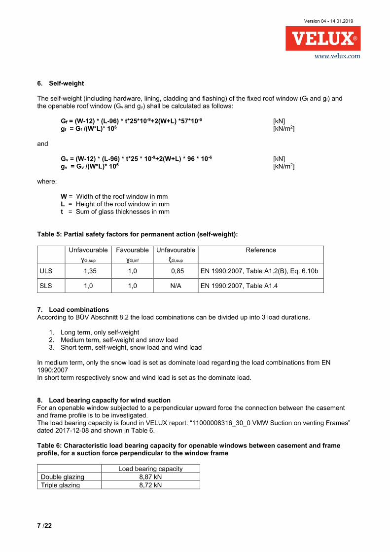
𝛼𝛼𝑐𝑐𝑐𝑐𝑐𝑐 = 𝛼𝛼 − ∆𝛼𝛼 = 25𝑐𝑐 − 0,7𝑐𝑐 = 24,3𝑐𝑐 For deflection calculations of an upwards load for an openable window, only the casement will deflect. Therefore only the height of the casement profile and correct angle hereof should be used for the deflections calculations. From Figure 4 ∆L1,up,dfl = -9,7 mm, ∆L2ll,up,dfl = 23,5 mm and ∆L2┴,up,dfl = 24 mm are found. The corrected height Lcor,up,dfl can thereby by found:
𝐿𝐿𝑐𝑐𝑐𝑐𝑐𝑐,𝑠𝑠𝑠𝑠,𝑑𝑑𝑖𝑖𝑙𝑙 = ��𝐿𝐿 + ∆𝐿𝐿1,𝑠𝑠𝑠𝑠,𝑑𝑑𝑖𝑖𝑙𝑙 + ∆𝐿𝐿2𝑙𝑙𝑙𝑙,𝑠𝑠𝑠𝑠,𝑑𝑑𝑖𝑖𝑙𝑙�2 + �𝐿𝐿2⊥,𝑠𝑠𝑠𝑠,𝑑𝑑𝑖𝑖𝑙𝑙�
2
= �(2400𝑚𝑚𝑚𝑚 − 9,7𝑚𝑚𝑚𝑚 + 23,5𝑚𝑚𝑚𝑚)2 + (24𝑚𝑚𝑚𝑚)2 = 2414𝑚𝑚𝑚𝑚 The corrected angle is found:
∆𝛼𝛼𝑠𝑠𝑠𝑠,𝑑𝑑𝑖𝑖𝑙𝑙 = sin−1 �𝐿𝐿2⊥,𝑠𝑠𝑠𝑠,𝑑𝑑𝑖𝑖𝑙𝑙
𝐿𝐿 + ∆𝐿𝐿1,𝑠𝑠𝑠𝑠,𝑑𝑑𝑖𝑖𝑙𝑙 + ∆𝐿𝐿2𝑙𝑙𝑙𝑙,𝑠𝑠𝑠𝑠,𝑑𝑑𝑖𝑖𝑙𝑙�
= sin−1 �24𝑚𝑚𝑚𝑚
2400𝑚𝑚𝑚𝑚 − 9,7𝑚𝑚𝑚𝑚 + 23,5𝑚𝑚𝑚𝑚� = 0,57𝑐𝑐
𝛼𝛼𝑐𝑐𝑐𝑐𝑐𝑐,𝑠𝑠𝑠𝑠,𝑑𝑑𝑖𝑖𝑙𝑙 = 𝛼𝛼 + ∆𝛼𝛼𝑠𝑠𝑠𝑠,𝑑𝑑𝑖𝑖𝑙𝑙 = 25𝑐𝑐 + 0,6𝑐𝑐 = 25,6𝑐𝑐 Figure 4: Corrections vectors for an openable window subjected to an upwards acting force, deflections only
The measurements ∆L1,up,dfl = -9,7 mm, ∆L2ll,up,dfl = 23,5 mm and ∆L2┴,up,dfl = 24 mm are constants. Characteristic loads Self-weight on each side frame/casement:
𝐺𝐺𝑉𝑉,𝑘𝑘 = 12∙ �(𝑊𝑊 − 12) ∙ (𝐿𝐿 − 96) ∙ 𝑡𝑡 ∙ 25 ∙ 10−9 + 2 ∙ (𝑊𝑊 + 𝐿𝐿) ∙ 96 ∙ 10−6�
= 12∙ �(1000 − 12) ∙ (2400 − 96) ∙ 14 ∙ 25 ∙ 10−9 + 2 ∙ (1000 + 2400) ∙ 96 ∙ 10−6� = 0.72𝑘𝑘𝑘𝑘
To be able to divide the self-weight up in sup and inf, the self-weight is given for the left and the right

Version 04 - 14.01.2019
13 /22
www.velux.com
frame/casement. 𝐺𝐺𝑉𝑉𝑉𝑉,𝑘𝑘 = 𝐺𝐺𝑉𝑉𝑉𝑉,𝑘𝑘 = 0,72𝑘𝑘𝑘𝑘 In this example, the wind peak velocity pressure (qp,k) is set to 0,8kN/m2 and the shape factor (c) is set to 0,5 for wind pressure and -0,5 for wind suction. Hence, the load is 𝑞𝑞𝑐𝑐,𝑘𝑘 = 𝑞𝑞𝑠𝑠,𝑘𝑘 = 𝑞𝑞𝑝𝑝,𝑘𝑘 ∙ 𝑐𝑐 ∙ 𝑊𝑊 2⁄ = 0,8𝑘𝑘𝑘𝑘/𝑚𝑚2 ∙ 0,5 ∙ 1,0𝑚𝑚 2⁄ = 0,2𝑘𝑘𝑘𝑘/𝑚𝑚 , 𝑜𝑜𝑜𝑜 𝑒𝑒𝑒𝑒𝑐𝑐ℎ 𝑠𝑠𝑠𝑠𝑠𝑠𝑒𝑒 𝑓𝑓𝑓𝑓𝑒𝑒𝑚𝑚𝑒𝑒/𝑐𝑐𝑒𝑒𝑠𝑠𝑒𝑒𝑚𝑚𝑒𝑒𝑜𝑜𝑡𝑡
The wind load is split into a vertical and a horizontal component, using the original angle α. Using the corrected height, Lcor to find the equivalent concentrated load.
𝑄𝑄𝑠𝑠𝑠𝑠,𝑘𝑘 = 𝑄𝑄𝑐𝑐𝑠𝑠,𝑘𝑘 = 𝑞𝑞𝑐𝑐,𝑘𝑘 ∙ 𝐿𝐿𝑐𝑐𝑐𝑐𝑐𝑐 ∙ sin(𝛼𝛼) = 0,2𝑘𝑘𝑘𝑘/𝑚𝑚 ∙ 2,543𝑚𝑚 ∙ sin(25𝑐𝑐) = 0,21𝑘𝑘𝑘𝑘 𝑜𝑜𝑜𝑜 𝑒𝑒𝑒𝑒𝑐𝑐ℎ 𝑠𝑠𝑠𝑠𝑠𝑠𝑒𝑒 𝑓𝑓𝑓𝑓𝑒𝑒𝑚𝑚𝑒𝑒/𝑐𝑐𝑒𝑒𝑠𝑠𝑒𝑒𝑚𝑚𝑒𝑒𝑜𝑜𝑡𝑡
𝑄𝑄𝑠𝑠𝑉𝑉,𝑘𝑘 = 𝑄𝑄𝑐𝑐𝑉𝑉,𝑘𝑘 = 𝑞𝑞𝑐𝑐,𝑘𝑘 ∙ 𝐿𝐿𝑐𝑐𝑐𝑐𝑐𝑐 ∙ cos(𝛼𝛼) = 0,2𝑘𝑘𝑘𝑘/𝑚𝑚 ∙ 2,543𝑚𝑚 ∙ cos(25𝑐𝑐) = 0,46𝑘𝑘𝑘𝑘 𝑜𝑜𝑜𝑜 𝑒𝑒𝑒𝑒𝑐𝑐ℎ 𝑠𝑠𝑠𝑠𝑠𝑠𝑒𝑒 𝑓𝑓𝑓𝑓𝑒𝑒𝑚𝑚𝑒𝑒/𝑐𝑐𝑒𝑒𝑠𝑠𝑒𝑒𝑚𝑚𝑒𝑒𝑜𝑜𝑡𝑡
For the snow load in this example the two C factors (according to EN 1991-1-3) are set to 1,0, the shape factor µ2 set to 0,8 and the characteristic value of snow load on the ground Sk=1,0kN/m2, given the characteristic snow load sk: 𝑠𝑠𝑘𝑘 = 𝜇𝜇2 ∙ 𝐶𝐶𝑒𝑒 ∙ 𝐶𝐶𝑡𝑡 ∙ 𝑆𝑆𝑘𝑘 = 0,8 ∙ 1,0 ∙ 1,0 ∙ 1,0𝑘𝑘𝑘𝑘 𝑚𝑚2⁄ = 0,8𝑘𝑘𝑘𝑘 𝑚𝑚2⁄ → 𝑠𝑠𝑠𝑠,𝑘𝑘 = 0,4𝑘𝑘𝑘𝑘/𝑚𝑚 , 𝑜𝑜𝑜𝑜 𝑒𝑒𝑒𝑒𝑐𝑐ℎ 𝑠𝑠𝑠𝑠𝑠𝑠𝑒𝑒 𝑓𝑓𝑓𝑓𝑒𝑒𝑚𝑚𝑒𝑒/𝑐𝑐𝑒𝑒𝑠𝑠𝑒𝑒𝑚𝑚𝑒𝑒𝑜𝑜𝑡𝑡 The snow load is only vertical, and the corrected height Lcor is used to find the equivalent concentrated load. 𝑆𝑆𝑉𝑉,𝑘𝑘 = 𝑠𝑠 ∙ cos(𝛼𝛼) ∙ 𝐿𝐿𝑐𝑐𝑐𝑐𝑐𝑐 = 0,4𝑘𝑘𝑘𝑘/𝑚𝑚 ∙ cos(25𝑐𝑐) ∙ 2,543𝑚𝑚 = 0,92𝑘𝑘𝑘𝑘 Reactions in brackets The corrected height Lcor and angle αcor are used in the static system to determine the reactions. These calculations are not presented here. Reactions are calculated separately for each load type and are found in Table 10. From the characteristic reactions, different load combinations are made from the partial safety factors found in Table 8a. CC2 (see EN 1990:2007, Table B1) is assumed: a) Characteristic load combination: 1,0 ∙ 𝐺𝐺𝑉𝑉𝑉𝑉.𝑘𝑘 + 1,0 ∙ 𝐺𝐺𝑉𝑉𝑉𝑉,𝑘𝑘 + 1,0 ∙ 𝑄𝑄𝑘𝑘 + 1,0 ∙ 𝑆𝑆𝑉𝑉,𝑘𝑘 b) Long term: Dominant self-weight combination: 𝛾𝛾𝐺𝐺,𝑠𝑠𝑠𝑠𝑠𝑠 ∙ 𝐺𝐺𝑉𝑉𝑉𝑉,𝑘𝑘 + 𝛾𝛾𝐺𝐺,𝑠𝑠𝑠𝑠𝑠𝑠 ∙ 𝐺𝐺𝑉𝑉𝑉𝑉,𝑘𝑘 => 1,35 ∙ 𝐺𝐺𝑉𝑉𝑉𝑉,𝑘𝑘 + 1,35 ∙ 𝐺𝐺𝑉𝑉𝑉𝑉,𝑘𝑘 c) Medium term: Dominant snow combination: 𝛾𝛾𝐺𝐺,𝑖𝑖𝑖𝑖𝑖𝑖 ∙ 𝐺𝐺𝑉𝑉𝑉𝑉,𝑘𝑘 + 𝛾𝛾𝐺𝐺,𝑠𝑠𝑠𝑠𝑠𝑠 ∙ 𝜉𝜉𝐺𝐺,𝑠𝑠𝑠𝑠𝑠𝑠 ∙ 𝐺𝐺𝑉𝑉𝑉𝑉,𝑘𝑘 + 𝛾𝛾𝑄𝑄,1 ∙ 𝑆𝑆𝑉𝑉,𝑘𝑘 => 1,0 ∙ 𝐺𝐺𝑉𝑉𝑉𝑉,𝑘𝑘 + 1,35 ∙ 0,85 ∙ 𝐺𝐺𝑉𝑉𝑉𝑉,𝑘𝑘 + 1,5 ∙ 𝑆𝑆𝑉𝑉,𝑘𝑘 d) Short term: Dominant wind combination, with snow: 𝛾𝛾𝐺𝐺,𝑖𝑖𝑖𝑖𝑖𝑖 ∙ 𝐺𝐺𝑉𝑉𝑉𝑉,𝑘𝑘 + 𝛾𝛾𝐺𝐺,𝑠𝑠𝑠𝑠𝑠𝑠 ∙ 𝜉𝜉𝐺𝐺,𝑠𝑠𝑠𝑠𝑠𝑠 ∙ 𝐺𝐺𝑉𝑉𝑉𝑉,𝑘𝑘 + 𝛾𝛾𝑄𝑄,1 ∙ 𝑄𝑄𝑘𝑘 + 𝛾𝛾𝑄𝑄,𝑖𝑖 ∙ Ψ0,𝑠𝑠𝑖𝑖𝑐𝑐𝑠𝑠 ∙ 𝑆𝑆𝑉𝑉,𝑘𝑘 => 1,0 ∙ 𝐺𝐺𝑉𝑉𝑉𝑉,𝑘𝑘 + 1,35 ∙ 0,85 ∙ 𝐺𝐺𝑉𝑉𝑉𝑉,𝑘𝑘 + 1,5 ∙ 𝑄𝑄𝑘𝑘 + 1,5 ∙ 0,5 ∙ 𝑆𝑆𝑉𝑉,𝑘𝑘 e) Short term: Dominant wind combination, without snow: 𝛾𝛾𝐺𝐺,𝑖𝑖𝑖𝑖𝑖𝑖 ∙ 𝐺𝐺𝑉𝑉𝑉𝑉,𝑘𝑘 + 𝛾𝛾𝐺𝐺,𝑠𝑠𝑠𝑠𝑠𝑠 ∙ 𝜉𝜉𝐺𝐺,𝑠𝑠𝑠𝑠𝑠𝑠 ∙ 𝐺𝐺𝑉𝑉𝑉𝑉,𝑘𝑘 + 𝛾𝛾𝑄𝑄,1 ∙ 𝑄𝑄𝑘𝑘 => 1,0 ∙ 𝐺𝐺𝑉𝑉𝑉𝑉,𝑘𝑘 + 1,35 ∙ 0,85 ∙ 𝐺𝐺𝑉𝑉𝑉𝑉,𝑘𝑘 + 1,5 ∙ 𝑄𝑄𝑘𝑘 f) Short term: Dominant snow combination, with wind: 𝛾𝛾𝐺𝐺,𝑖𝑖𝑖𝑖𝑖𝑖 ∙ 𝐺𝐺𝑉𝑉𝑉𝑉,𝑘𝑘 + 𝛾𝛾𝐺𝐺,𝑠𝑠𝑠𝑠𝑠𝑠 ∙ 𝜉𝜉𝐺𝐺,𝑠𝑠𝑠𝑠𝑠𝑠 ∙ 𝐺𝐺𝑉𝑉𝑉𝑉,𝑘𝑘 + 𝛾𝛾𝑄𝑄,𝑖𝑖 ∙ Ψ0,𝑠𝑠𝑖𝑖𝑖𝑖𝑑𝑑 ∙ 𝑄𝑄𝑘𝑘 + 𝛾𝛾𝑄𝑄,1 ∙ 𝑆𝑆𝑉𝑉,𝑘𝑘 => 1,0 ∙ 𝐺𝐺𝑉𝑉𝑉𝑉,𝑘𝑘 + 1,35 ∙ 0,85 ∙ 𝐺𝐺𝑉𝑉𝑉𝑉,𝑘𝑘 + 1,5 ∙ 0,6 ∙ 𝑄𝑄𝑘𝑘 + 1,5 ∙ 𝑆𝑆𝑉𝑉,𝑘𝑘

Version 04 - 14.01.2019
14 /22
www.velux.com
Table 10, Horizontal and vertical reactions of the brackets
Load type RH1L [kN]
RV1L [kN]
RH2L [kN]
RV2L [kN]
RH2R [kN]
RV2R [kN]
RH1R [kN]
RV1R [kN]
GVL,k 0,40 0,54 0,40 -0,18 0,40 -0,18 0,40 0,18 GVR,k 0,40 0,18 0,40 0,18 0,40 0,18 0,40 0,54 Qk (Qs,k and Qc,k) 0,21 -0,18 0,00 0,28 0,00 0,28 -0,21 0,18 SV,k 0,51 0,23 0,51 0,23 0,51 0,23 0,51 0,69 a) Characteristic combi. 1,52 0,77 1,31 0,51 1,31 0,51 1,10 1,59 b) Long term: Dom. self-weight 1,08 0,97 1,08 0,00 1,08 0,00 1,08 0,97 c) Medium term: Dom. snow 1,62 1,09 1,62 0,37 1,62 0,37 1,62 1,83 d) Short term: Dom. wind 1,55 0,65 1,24 0,62 1,24 0,62 0,92 1,59 e) Short term: Dom. wind, -snow 1,17 0,47 0,86 0,44 0,86 0,44 0,54 1,07 f) Short term: Dom. snow 1,81 0,93 1,62 0,62 1,62 0,62 1,43 2,00
The factors to find the design value of the load bearing capacity of the bracket are found from the formula given in Clause 2 and Table 8b. Duration is divided up in long term (25 years), medium term (3 month) and short term (10 min), and temperature is taken for the highest it can be, 20°C when snow and 60°C when without snow. Hence self-weight is set to the lifespan of the window, snow duration is set to 3 months and wind duration set to 10 minutes. Snow duration may differ from region to region and should be changes accordingly. Long term: Dominant self-weight combination, duration: 25 years, temperature: 60°C 𝒃𝒃) 𝑓𝑓𝑒𝑒𝑐𝑐𝑡𝑡𝑜𝑜𝑓𝑓 = 𝛾𝛾𝑀𝑀𝑉𝑉 ∙ 𝐾𝐾𝑡𝑡,25𝑦𝑦𝑒𝑒𝑦𝑦𝑐𝑐𝑠𝑠 ∙ 𝐾𝐾𝑠𝑠 ∙ 𝐾𝐾𝜃𝜃,60𝑜𝑜 = 1,5 ∙ 2,02 ∙ 1,2 ∙ 1,5 = 5,45 Medium term: Dominant snow combination, duration: 3 months, temperature: 20°C: 𝒄𝒄) 𝑓𝑓𝑒𝑒𝑐𝑐𝑡𝑡𝑜𝑜𝑓𝑓 = 𝛾𝛾𝑀𝑀𝑉𝑉 ∙ 𝐾𝐾𝑡𝑡,3𝑚𝑚𝑐𝑐𝑖𝑖𝑡𝑡ℎ𝑠𝑠 ∙ 𝐾𝐾𝑠𝑠 ∙ 𝐾𝐾𝜃𝜃,20𝑜𝑜 = 1,5 ∙ 1,66 ∙ 1,2 ∙ 1,0 = 2,99 Short term: Dominant wind combination, duration: 10 minutes, temperature: 20°C: 𝒅𝒅) 𝑓𝑓𝑒𝑒𝑐𝑐𝑡𝑡𝑜𝑜𝑓𝑓 = 𝛾𝛾𝑀𝑀𝑉𝑉 ∙ 𝐾𝐾𝑡𝑡,10 𝑚𝑚𝑖𝑖𝑖𝑖 ∙ 𝐾𝐾𝑠𝑠 ∙ 𝐾𝐾𝜃𝜃,20 = 1,5 ∙ 1,1 ∙ 1,2 ∙ 1,0 = 1,98 Short term: Dominant wind combination, no snow load, duration: 10 minutes, temperature: 60°C: 𝒆𝒆) 𝑓𝑓𝑒𝑒𝑐𝑐𝑡𝑡𝑜𝑜𝑓𝑓 = 𝛾𝛾𝑀𝑀𝑉𝑉 ∙ 𝐾𝐾𝑡𝑡,10 𝑚𝑚𝑖𝑖𝑖𝑖 ∙ 𝐾𝐾𝑠𝑠 ∙ 𝐾𝐾𝜃𝜃,60 = 1,5 ∙ 1,1 ∙ 1,2 ∙ 1,5 = 2,97 Short term: Dominant snow combination, duration: 10 minutes, temperature: 20°C: 𝒇𝒇) 𝑓𝑓𝑒𝑒𝑐𝑐𝑡𝑡𝑜𝑜𝑓𝑓 = 𝛾𝛾𝑀𝑀𝑉𝑉 ∙ 𝐾𝐾𝑡𝑡,10 𝑚𝑚𝑖𝑖𝑖𝑖 ∙ 𝐾𝐾𝑠𝑠 ∙ 𝐾𝐾𝜃𝜃,20 = 1,5 ∙ 1,1 ∙ 1,2 ∙ 1,0 = 1,98 The resulting bracket forces and utilization hereof are found in Table 11a to 11f for the load combinations. The load bearing capacities of the brackets in the resulting angle are found by linear interpolation between the two-neighbouring load bearing capacities, see Figure 2 and Table 9. Table 11a, Brackets forces (resultants) and utilization for the characteristic load combination
a) Characteristic combi. R1L R2L R2R R1R Characteristic bracket reaction force 1,70 kN 1,40 kN 1,40 kN 1,93 kN
Angle according to Figure 1 1,8° 176,2° 133,8° 30,4°
Characteristic load bearing capacity 12,40 kN 12,93 kN 9,21 kN 13,34 kN
Utilization 14 % 11 % 15 % 14 %
Version 04 - 14.01.2019
15 /22
www.velux.com
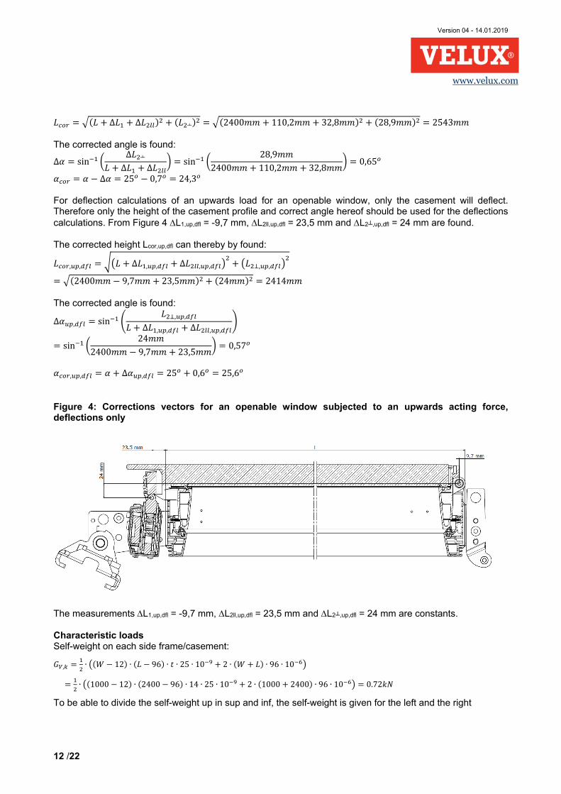
Table 11b, Brackets forces (resultants) and utilization for the long term dominant self-weight load combination
b) Long term: Dom. self-weight R1L R2L R2R R1R
Design bracket reaction force 1,45 kN 1,08 kN 1,08 kN 1,45 kN
Angle according to Figure 1 17,1° 155,0° 155,0° 17,1°
Characteristic load bearing capacity 16,55 kN 14,86 kN 14,86 kN 16,55 kN
Design load bearing capacity 3,04 2,73 2,73 3,04
Utilization 48 % 39 % 39 % 48 % Table 11c, Brackets forces (resultants) and utilization for the medium term dominant snow load combination
c) Medium term: Dom. snow R1L R2L R2R R1R
Design bracket reaction force 1,95 kN 1,66 kN 1,66 kN 2,45 kN
Angle according to Figure 1 9,0° 167,9° 142,1° 23,6°
Characteristic load bearing capacity 14,34 kN 15,19 kN 11,27 kN 15,26 kN
Design load bearing capacity 4,80 kN 5,08 kN 3,77 kN 5,10 kN
Utilization 41 % 33 % 44 % 48 % Table 11d, Brackets forces (resultants) and utilization for the short term dominant wind load combination
d) Short term: Dom. wind R1L R2L R2R R1R
Design bracket reaction force 1,68 kN 1,38 kN 1,38 kN 1,84 kN
Angle according to Figure 1 357,6 o 181,4 o 128,6 o 34,9 o
Characteristic load bearing capacity 11,15 kN 11,47 kN 8,83 kN 12,11 kN
Design load bearing capacity 5,63 kN 5,79 kN 4,46 kN 6,12 kN
Utilization 30 % 24 % 31 % 30 %

Version 04 - 14.01.2019
16 /22
www.velux.com
Table 11e, Brackets forces (resultants) and utilization for the short term dominant wind, without snow load combination
e) Short term: Dom. wind, -snow R1L R2L R2R R1R
Design bracket reaction force 1,26 kN 0,96 kN 0,96 kN 1,20 kN
Angle according to Figure 1 357,0° 182,3° 127,7° 38,3°
Characteristic load bearing capacity 10,98 kN 11,18 kN 8,76 kN 11,17 kN
Design load bearing capacity 3,70 kN 3,77 kN 2,95 kN 3,76 kN
Utilization 34 % 26 % 33 % 32 % Table 11f, Brackets forces (resultants) and utilization for the short term dominant snow load combination
f) Short term: Dom. snow R1L R2L R2R R1R
Design bracket reaction force 2,03 kN 1,74 kN 1,74 kN 2,46 kN
Angle according to Figure 1 2,1° 176,0° 134,0° 29,4°
Characteristic load bearing capacity 12,48 kN 12,99 kN 9,23 kN 13,63 kN
Design load bearing capacity 6,30 kN 6,56 kN 4,66 kN 6,89 kN
Utilization 32 % 26 % 37 % 36 % Load bearing capacity for wind suction Since it is an openable window and the left side is subjected to wind suction, the load bearing capacity hereof is checked. Dimension of the glass is found in Figure 5. The 60 mm protruded part is toughened glass with a thickness of 8 mm. The glass self-weight can hereby be found with a glass density of γglass= 25 kN/m3. 𝐺𝐺𝑔𝑔𝑔𝑔𝑒𝑒𝑠𝑠𝑠𝑠,𝑘𝑘 = �(𝐿𝐿 − 0,056𝑚𝑚) ∙ 𝑡𝑡+ 0,060𝑚𝑚 ∙ 0,008𝑚𝑚� ∙ (𝑊𝑊− 0,022𝑚𝑚) ∙ 𝛾𝛾𝑔𝑔𝑔𝑔𝑒𝑒𝑠𝑠𝑠𝑠 = �(2,4− 0,056𝑚𝑚) ∙ 0,014 + 0,060𝑚𝑚 ∙ 0,008𝑚𝑚� ∙ (1,0− 0,022𝑚𝑚) ∙ 25 𝑘𝑘𝑘𝑘/𝑚𝑚3 = 0,81𝑘𝑘𝑘𝑘 The weight of the openable window casement profile is set to: 𝑔𝑔𝑐𝑐𝑦𝑦𝑠𝑠𝑒𝑒,𝑘𝑘 = 𝐴𝐴𝑐𝑐𝑦𝑦𝑠𝑠𝑒𝑒 ∙ 𝛾𝛾𝑖𝑖𝑐𝑐𝑦𝑦𝑚𝑚𝑒𝑒 ∙ 𝑔𝑔 = 8,57 ∙ 10−4𝑚𝑚2 ∙ 2076𝑘𝑘𝑔𝑔/𝑚𝑚3 ∙ 9,81𝑚𝑚/𝑠𝑠2 = 0,017𝑘𝑘𝑘𝑘/𝑚𝑚 Here, the area of the casement profiles (Acase) is taken from Annex C4 and the density (γframe) is taken from Annex D.1 in ETA-17/0467.

Version 04 - 14.01.2019
17 /22
www.velux.com
Figure 5: Glass dimension for openable window
The perimeter of the casement Lcase is found, see also Figure 6: 𝐿𝐿𝑐𝑐𝑒𝑒𝑠𝑠𝑒𝑒 = 2 ∙ (𝐿𝐿 − 0,041𝑚𝑚) + 2 ∙ (𝑊𝑊− 0,041𝑚𝑚) = 2 ∙ (2,4− 0,041𝑚𝑚) + 2 ∙ (1,0− 0,041𝑚𝑚) =6,64m The total characteristic self-weight perpendicular to the openable window (𝐺𝐺⊥,𝑘𝑘) is found to: 𝐺𝐺⊥,𝑘𝑘 = (𝐺𝐺𝑔𝑔𝑙𝑙𝑦𝑦𝑠𝑠𝑠𝑠,𝑘𝑘 + 𝑔𝑔𝑐𝑐𝑦𝑦𝑠𝑠𝑒𝑒,𝑘𝑘 ∙ 𝐿𝐿𝑐𝑐𝑦𝑦𝑠𝑠𝑒𝑒) ∙ cos (𝛼𝛼) = (0,81𝑘𝑘𝑘𝑘 + 0,017𝑘𝑘𝑘𝑘/𝑚𝑚 ∙ 6,64𝑚𝑚) ∙ cos (25°) = 0,84𝑘𝑘𝑘𝑘

Version 04 - 14.01.2019
18 /22
www.velux.com
Figure 6: Dimension for casement profile for openable window
Glass area (AW,suc) for which the wind suctions acts upon: 𝐴𝐴𝑊𝑊,𝑠𝑠𝑠𝑠𝑐𝑐 = �(𝐿𝐿 − 0,056𝑚𝑚) + 0,060𝑚𝑚� ∙ (𝑊𝑊 − 0,022𝑚𝑚) = �(2,4 − 0,056𝑚𝑚) + 0,060𝑚𝑚� ∙ (1,0 − 0,022𝑚𝑚) = 2,35𝑚𝑚2 The characteristic wind suction perpendicular of the openable window (𝑄𝑄𝑠𝑠⊥,𝑘𝑘) is found
𝑄𝑄𝑠𝑠⊥,𝑘𝑘 = 𝑞𝑞𝑠𝑠,𝑘𝑘 ∙ 𝑐𝑐 ∙ 𝐴𝐴𝑊𝑊,𝑠𝑠𝑠𝑠𝑐𝑐 = 0,8𝑘𝑘𝑘𝑘/𝑚𝑚2 ∙ 0,5 ∙ 2,35𝑚𝑚2 = 0,94𝑘𝑘𝑘𝑘
The load combination e) short term dominant wind, no snow load, is the worst case for wind suction on the window. Giving a total design load perpendicular to the window (𝑃𝑃⊥𝑑𝑑): 𝑃𝑃⊥𝑑𝑑 = 𝛾𝛾𝑄𝑄,1 ∙ 𝑄𝑄𝑠𝑠⊥,𝑘𝑘 − 𝛾𝛾𝐺𝐺,𝑖𝑖𝑖𝑖𝑖𝑖 ∙ 𝐺𝐺⊥,𝑘𝑘 = 1,5 ∙ 0,94𝑘𝑘𝑘𝑘 − 1,0 ∙ 0,84𝑘𝑘𝑘𝑘 = 0,57𝑘𝑘𝑘𝑘 The characteristic load bearing capacity (Rk) is taken from Clause 8, Table 6 for double glazing: 𝑅𝑅𝑘𝑘 = 8,87 𝑘𝑘𝑘𝑘 Reduction safety factor for short term: Dominant wind combination, no snow load, duration: 10 minutes, temperature: 60°C is found to: 𝒆𝒆) 𝑓𝑓𝑒𝑒𝑐𝑐𝑡𝑡𝑜𝑜𝑓𝑓 = 𝛾𝛾𝑀𝑀𝑉𝑉 ∙ 𝐾𝐾𝑡𝑡,10 𝑚𝑚𝑖𝑖𝑖𝑖 ∙ 𝐾𝐾𝑠𝑠 ∙ 𝐾𝐾𝜃𝜃,60 = 1,5 ∙ 1,1 ∙ 1,2 ∙ 1,5 = 2,97

Version 04 - 14.01.2019
19 /22
www.velux.com
Design load bearing capacity (Rd):
𝑅𝑅𝑑𝑑 =8,87𝑘𝑘𝑘𝑘
2,97= 2,99𝑘𝑘𝑘𝑘
Utilization: 𝑃𝑃⊥𝑑𝑑/𝑅𝑅𝑑𝑑 ∙ 100 = 0,57𝑘𝑘𝑘𝑘/2,99𝑘𝑘𝑘𝑘 ∙ 100 = 19% Bending in frame and casement profile The bending in frame and casement profile is in this example only calculated for the medium term dominate snow combination, hereby showing the calculations procedure. Normally all load combination should be investigated.
Design capacity of frame and casement, duration: 3 months, temperature: 20°C:
𝜎𝜎𝑉𝑉,𝑑𝑑 =𝜎𝜎𝑉𝑉,𝑘𝑘
𝛾𝛾𝑀𝑀𝑉𝑉 ∙ 𝐾𝐾𝑡𝑡,3 𝑚𝑚𝑐𝑐𝑖𝑖𝑡𝑡ℎ ∙ 𝐾𝐾𝑠𝑠 ∙ 𝐾𝐾𝜃𝜃,20𝑜𝑜=
1257𝑘𝑘/𝑚𝑚𝑚𝑚2
1,2 ∙ 1,66 ∙ 1,2 ∙ 1,0= 526𝑘𝑘/𝑚𝑚𝑚𝑚2
(For characteristic bending strength see Table 3, for partial safety factors see Table 8a/ULS and for magnification and reduction factors see Table 8b/ULS.) The characteristic line load from self-weight perpendicular to the roof window is denoted gp,k and perpendicular line load from the characteristic snow pressure is denoted sp,k. The corrected height is applied but the original angle is used:
𝑔𝑔𝑠𝑠,𝑘𝑘 =𝐺𝐺𝑉𝑉𝑉𝑉,𝑘𝑘 ∙ 𝑐𝑐𝑜𝑜𝑠𝑠 (𝛼𝛼)
𝐿𝐿𝑐𝑐𝑐𝑐𝑐𝑐=
0,72 ∙ 𝑐𝑐𝑜𝑜𝑠𝑠 (25)2,543 = 0,26𝑘𝑘𝑘𝑘/𝑚𝑚 , 𝑜𝑜𝑜𝑜 𝑒𝑒𝑒𝑒𝑐𝑐ℎ 𝑠𝑠𝑠𝑠𝑠𝑠𝑒𝑒 𝑓𝑓𝑓𝑓𝑒𝑒𝑚𝑚𝑒𝑒/𝑐𝑐𝑒𝑒𝑠𝑠𝑒𝑒𝑚𝑚𝑒𝑒𝑜𝑜𝑡𝑡
𝑠𝑠𝑠𝑠,𝑘𝑘 = 𝑠𝑠𝑠𝑠,𝑘𝑘 ∙ cos (𝛼𝛼) = 0,40𝑘𝑘𝑘𝑘/𝑚𝑚 ∙ cos (25) = 0,36𝑘𝑘𝑘𝑘/𝑚𝑚 , 𝑜𝑜𝑜𝑜 𝑒𝑒𝑒𝑒𝑐𝑐ℎ 𝑠𝑠𝑠𝑠𝑠𝑠𝑒𝑒 𝑓𝑓𝑓𝑓𝑒𝑒𝑚𝑚𝑒𝑒/𝑐𝑐𝑒𝑒𝑠𝑠𝑒𝑒𝑚𝑚𝑒𝑒𝑜𝑜𝑡𝑡
𝑀𝑀𝑑𝑑 =18 ∙ �𝛾𝛾𝐺𝐺,𝑠𝑠𝑠𝑠𝑠𝑠 ∙ 𝜉𝜉𝐺𝐺,𝑠𝑠𝑠𝑠𝑠𝑠 ∙ 𝑔𝑔𝑠𝑠,𝑘𝑘 + 𝛾𝛾𝑄𝑄,1 ∙ 𝑠𝑠𝑠𝑠,𝑘𝑘� ∙ 𝐿𝐿𝑐𝑐𝑐𝑐𝑐𝑐2
=18 ∙
(1,35 ∙ 0,85 ∙ 0,26 + 1,5 ∙ 0,36)𝑘𝑘𝑘𝑘/𝑚𝑚 ∙ (2,543𝑚𝑚)2 = 0,68𝑘𝑘𝑘𝑘𝑚𝑚
𝑀𝑀𝑖𝑖𝑐𝑐𝑦𝑦𝑚𝑚𝑒𝑒,𝑑𝑑 = 𝑀𝑀𝑑𝑑 ∙ 𝐼𝐼𝑓𝑓𝑓𝑓𝑓𝑓𝑓𝑓𝑓𝑓𝐼𝐼𝑓𝑓𝑓𝑓𝑓𝑓𝑓𝑓𝑓𝑓+𝐼𝐼𝑐𝑐𝑓𝑓𝑐𝑐𝑓𝑓𝑓𝑓𝑓𝑓𝑐𝑐𝑐𝑐
= 0,68𝑘𝑘𝑘𝑘𝑚𝑚 ∙ 0,669∙106𝑚𝑚𝑚𝑚4
0,669∙106𝑚𝑚𝑚𝑚4+0,930∙106𝑚𝑚𝑚𝑚4 = 0,28𝑘𝑘𝑘𝑘𝑚𝑚
𝜎𝜎𝑖𝑖𝑐𝑐𝑦𝑦𝑚𝑚𝑒𝑒,𝑑𝑑 ≈𝑀𝑀𝑓𝑓𝑓𝑓𝑓𝑓𝑓𝑓𝑓𝑓,𝑑𝑑
𝑊𝑊𝑦𝑦,𝑓𝑓𝑓𝑓𝑓𝑓𝑓𝑓𝑓𝑓= 0,28∙106𝑁𝑁𝑚𝑚𝑚𝑚
9,93∙103𝑚𝑚𝑚𝑚3 = 28,7𝑘𝑘/𝑚𝑚𝑚𝑚2
Utilization: 𝜎𝜎𝑓𝑓𝑓𝑓𝑓𝑓𝑓𝑓𝑓𝑓,𝑑𝑑
𝜎𝜎𝑅𝑅,𝑑𝑑∙ 100 = 28,7𝑁𝑁/𝑚𝑚𝑚𝑚2
526𝑁𝑁/𝑚𝑚𝑚𝑚2 ∙ 100 = 5,4%
𝑀𝑀𝑐𝑐𝑦𝑦𝑠𝑠𝑒𝑒𝑚𝑚𝑒𝑒𝑖𝑖𝑡𝑡,𝑑𝑑 = 𝑀𝑀𝑑𝑑 ∙ 𝐼𝐼𝑐𝑐𝑓𝑓𝑐𝑐𝑓𝑓𝑓𝑓𝑓𝑓𝑐𝑐𝑐𝑐𝐼𝐼𝑓𝑓𝑓𝑓𝑓𝑓𝑓𝑓𝑓𝑓+𝐼𝐼𝑐𝑐𝑓𝑓𝑐𝑐𝑓𝑓𝑓𝑓𝑓𝑓𝑐𝑐𝑐𝑐
= 0,68𝑘𝑘𝑘𝑘𝑚𝑚 ∙ 0,930∙106𝑚𝑚𝑚𝑚4
0,669∙106𝑚𝑚𝑚𝑚4+0,930∙106𝑚𝑚𝑚𝑚4 = 0,40𝑘𝑘𝑘𝑘𝑚𝑚
𝜎𝜎𝑐𝑐𝑦𝑦𝑠𝑠𝑒𝑒𝑚𝑚𝑒𝑒𝑖𝑖𝑡𝑡,𝑑𝑑 ≈𝑀𝑀𝑐𝑐𝑓𝑓𝑐𝑐𝑓𝑓𝑓𝑓𝑓𝑓𝑐𝑐𝑐𝑐,𝑑𝑑,𝑊𝑊𝑦𝑦,𝑐𝑐𝑓𝑓𝑐𝑐𝑓𝑓𝑓𝑓𝑓𝑓𝑐𝑐𝑐𝑐
= 0,40∙106𝑁𝑁𝑚𝑚𝑚𝑚16,4∙103𝑚𝑚𝑚𝑚3 = 24,1𝑘𝑘/𝑚𝑚𝑚𝑚2
Utilization: 𝜎𝜎𝑐𝑐𝑓𝑓𝑐𝑐𝑓𝑓𝑓𝑓𝑓𝑓𝑐𝑐𝑐𝑐,𝑑𝑑𝜎𝜎𝑅𝑅,𝑑𝑑
∙ 100 = 24,1𝑁𝑁/𝑚𝑚𝑚𝑚2
526𝑁𝑁/𝑚𝑚𝑚𝑚2 ∙ 100 = 4,6% Here, the characteristic bending strength is taken from Annex D.1 in ETA-17/0467. Second moment of area and section modulus are taken from Annex C.1 and C.4 in ETA-17/0467. The rotation of the main axis is ignored, as it has little influence on the result, and the resulting stress is much lower than the bending strength. Shear force in frame profile The shear force in frame profile is in this example only calculated for the medium term dominate snow combination, hereby showing the calculations procedure. Normally all load combination shall be investigated.
Design capacity shear stress of frame, duration: 3 months, temperature: 20°C:

Version 04 - 14.01.2019
20 /22
www.velux.com
𝜏𝜏𝑖𝑖𝑐𝑐𝑦𝑦𝑚𝑚𝑒𝑒,𝑉𝑉,𝑑𝑑 =𝜏𝜏𝑖𝑖𝑐𝑐𝑦𝑦𝑚𝑚𝑒𝑒,𝑉𝑉,𝑘𝑘
𝛾𝛾𝑀𝑀𝑉𝑉 ∙ 𝐾𝐾𝑡𝑡,3 𝑚𝑚𝑐𝑐𝑖𝑖𝑡𝑡ℎ ∙ 𝐾𝐾𝑠𝑠 ∙ 𝐾𝐾𝜃𝜃,20𝑜𝑜=
53,8𝑘𝑘/𝑚𝑚𝑚𝑚2
1,2 ∙ 1,66 ∙ 1,2 ∙ 1,0= 22,5𝑘𝑘/𝑚𝑚𝑚𝑚2
(For characteristic shear strength see Table 3, for partial safety factors see Table 8a/ULS and for magnification and reduction factors see Table 8b/ULS.) The shear force is generally taken in combination by the frame and casement profile, but near the ends of the roof window, the entire shear force is taken by the frame profile. The original angle is used. Largest shear force is in the right roof window in this example: 𝑉𝑉𝑖𝑖𝑐𝑐𝑦𝑦𝑚𝑚𝑒𝑒 = 𝑅𝑅𝑉𝑉1𝑉𝑉 ∙ 𝑐𝑐𝑜𝑜𝑠𝑠(𝛼𝛼) − 𝑅𝑅𝑠𝑠1𝑉𝑉∙ 𝑠𝑠𝑠𝑠𝑜𝑜(𝛼𝛼)
= 1,83𝑘𝑘𝑘𝑘 ∙ 𝑐𝑐𝑜𝑜𝑠𝑠(25) − 1,62𝑘𝑘𝑘𝑘 ∙ 𝑠𝑠𝑠𝑠𝑜𝑜 (25)
= 0,97𝑘𝑘𝑘𝑘
𝜏𝜏𝑖𝑖𝑐𝑐𝑦𝑦𝑚𝑚𝑒𝑒 = 𝑉𝑉𝑓𝑓𝑓𝑓𝑓𝑓𝑓𝑓𝑓𝑓
𝐴𝐴𝑤𝑤𝑓𝑓𝑤𝑤≈ 0,97∙103𝑁𝑁
550𝑚𝑚𝑚𝑚2 = 1,77𝑘𝑘/𝑚𝑚𝑚𝑚2
Utilization: 𝜏𝜏𝑓𝑓𝑓𝑓𝑓𝑓𝑓𝑓𝑓𝑓
𝜏𝜏𝑓𝑓𝑓𝑓𝑓𝑓𝑓𝑓𝑓𝑓,𝑅𝑅,𝑑𝑑∙ 100 = 1,77𝑁𝑁/𝑚𝑚𝑚𝑚2
22,5𝑁𝑁/𝑚𝑚𝑚𝑚2 ∙ 100 = 7,9%
Here, the characteristic shear strength is taken from Annex D.1 and Aweb from Annex C.1 in ETA-17/0467. Deflection Deflections are checked for each side separately and perpendicular to the corrected roof window angle. 6 SLS load combinations can therefore be made, for this load case: g) Long term: Dominant self-weight: 𝐺𝐺𝑉𝑉𝑉𝑉,𝑘𝑘 h) Medium term: Dominant snow: 𝐺𝐺𝑉𝑉𝑉𝑉,𝑘𝑘 + 𝑆𝑆𝑉𝑉,𝑘𝑘 i) Short term: Dominant wind pressure, with snow: 𝐺𝐺𝑉𝑉𝑉𝑉,𝑘𝑘 + 𝑄𝑄𝑐𝑐,𝑘𝑘 + Ψ0,𝑠𝑠𝑖𝑖𝑐𝑐𝑠𝑠 ∙ 𝑆𝑆𝑉𝑉,𝑘𝑘 => 𝐺𝐺𝑉𝑉𝑉𝑉,𝑘𝑘 + 𝑄𝑄𝑐𝑐,𝑘𝑘 + 0,5 ∙ 𝑆𝑆𝑉𝑉,𝑘𝑘 j) Short term: Dominant wind pressure, no snow 𝐺𝐺𝑉𝑉𝑉𝑉,𝑘𝑘 + 𝑄𝑄𝑐𝑐,𝑘𝑘 k) Short term: Dominant snow, with wind: 𝐺𝐺𝑉𝑉𝑉𝑉,𝑘𝑘 + Ψ0,𝑠𝑠𝑖𝑖𝑖𝑖𝑑𝑑 ∙ 𝑄𝑄𝑐𝑐,𝑘𝑘 + 𝑆𝑆𝑉𝑉,𝑘𝑘 => 𝐺𝐺𝑉𝑉𝑉𝑉,𝑘𝑘 + 0,6 ∙ 𝑄𝑄𝑐𝑐,𝑘𝑘 + 𝑆𝑆𝑉𝑉,𝑘𝑘 l) Short term: Dominant wind suction, no snow 𝐺𝐺𝑉𝑉𝑉𝑉,𝑘𝑘 + 𝑄𝑄𝑠𝑠,𝑘𝑘 The factors to find the design value of the deflection of the frame/casement are found from the formula given in Clause 2 and Table 8b. Duration is divided up in long term (25 years), medium term (3 month) and short term (10 min), and temperature is taken for the highest it can be, 20°C when snow and 60°C when without snow. Hence self-weight is set to the lifespan of the window, snow duration is set to 3 months and wind duration set to 10 minutes. Snow duration may differ from region to region and should be changes accordingly.

Version 04 - 14.01.2019
21 /22
www.velux.com
Long term: Dominant self-weight combination, duration: 25 years, temperature: 60°C: 𝒈𝒈) 𝑓𝑓𝑒𝑒𝑐𝑐𝑡𝑡𝑜𝑜𝑓𝑓 = 𝛾𝛾𝑀𝑀𝑀𝑀 ∙ 𝐶𝐶𝑡𝑡,25 𝑦𝑦𝑒𝑒𝑦𝑦𝑐𝑐𝑠𝑠 ∙ 𝐶𝐶𝑠𝑠 ∙ 𝐶𝐶𝜃𝜃,60𝑜𝑜 = 1,1 ∙ 1,15 ∙ 1,2 ∙ 1,05 = 1,59 Medium term: Dominant snow combination, duration: 3 months, temperature: 20°C: 𝒉𝒉) 𝑓𝑓𝑒𝑒𝑐𝑐𝑡𝑡𝑜𝑜𝑓𝑓 = 𝛾𝛾𝑀𝑀𝑀𝑀 ∙ 𝐶𝐶𝑡𝑡,3𝑚𝑚𝑐𝑐𝑖𝑖𝑡𝑡ℎ𝑠𝑠 ∙ 𝐶𝐶𝑠𝑠 ∙ 𝐶𝐶𝜃𝜃,20𝑜𝑜 = 1,1 ∙ 1,11 ∙ 1,2 ∙ 1,0 = 1,47 Short term: Dominant wind pressure combination, duration: 10 minutes, temperature: 20°C: 𝒊𝒊) 𝑓𝑓𝑒𝑒𝑐𝑐𝑡𝑡𝑜𝑜𝑓𝑓 = 𝛾𝛾𝑀𝑀𝑀𝑀 ∙ 𝐶𝐶𝑡𝑡,10𝑚𝑚𝑖𝑖𝑖𝑖 ∙ 𝐶𝐶𝑠𝑠 ∙ 𝐶𝐶𝜃𝜃,20𝑜𝑜 = 1,1 ∙ 1,02 ∙ 1,2 ∙ 1,0 = 1,35 Short term: Dominant wind pressure combination, no snow load, duration: 10 minutes, temperature: 60°C: 𝒋𝒋) 𝑓𝑓𝑒𝑒𝑐𝑐𝑡𝑡𝑜𝑜𝑓𝑓 = 𝛾𝛾𝑀𝑀𝑀𝑀 ∙ 𝐶𝐶𝑡𝑡,10𝑚𝑚𝑖𝑖𝑖𝑖 ∙ 𝐶𝐶𝑠𝑠 ∙ 𝐶𝐶𝜃𝜃,60𝑜𝑜 = 1,1 ∙ 1,02 ∙ 1,2 ∙ 1,05 = 1,41 Short term: Dominant snow combination, duration: 10 minutes, temperature: 20°C: 𝒌𝒌) 𝑓𝑓𝑒𝑒𝑐𝑐𝑡𝑡𝑜𝑜𝑓𝑓 = 𝛾𝛾𝑀𝑀𝑀𝑀 ∙ 𝐶𝐶𝑡𝑡,10𝑚𝑚𝑖𝑖𝑖𝑖 ∙ 𝐶𝐶𝑠𝑠 ∙ 𝐶𝐶𝜃𝜃,20𝑜𝑜 = 1,1 ∙ 1,02 ∙ 1,2 ∙ 1,0 = 1,35 Short term: Dominant wind suction combination, no snow load, duration: 10 minutes, temperature: 60°C: 𝒍𝒍) 𝑓𝑓𝑒𝑒𝑐𝑐𝑡𝑡𝑜𝑜𝑓𝑓 = 𝛾𝛾𝑀𝑀𝑀𝑀 ∙ 𝐶𝐶𝑡𝑡,10𝑚𝑚𝑖𝑖𝑖𝑖 ∙ 𝐶𝐶𝑠𝑠 ∙ 𝐶𝐶𝜃𝜃,60𝑜𝑜 = 1,1 ∙ 1,02 ∙ 1,2 ∙ 1,05 = 1,41 (For partial safety factors see Table 8a/SLS and for magnification and reduction factors see Table 8b/SLS). Characteristic Self-weight perpendicular to the corrected roof window angle:
𝑔𝑔𝑠𝑠,𝑐𝑐𝑐𝑐𝑐𝑐,𝑘𝑘 =𝐺𝐺𝑉𝑉 ∙ 𝑐𝑐𝑜𝑜𝑠𝑠 (𝛼𝛼𝑐𝑐𝑐𝑐𝑐𝑐)
𝐿𝐿𝑐𝑐𝑐𝑐𝑐𝑐=
0,72 ∙ 𝑐𝑐𝑜𝑜𝑠𝑠 (24,3)2,543 = 0,26𝑘𝑘𝑘𝑘/𝑚𝑚 , 𝑜𝑜𝑜𝑜 𝑒𝑒𝑒𝑒𝑐𝑐ℎ 𝑠𝑠𝑠𝑠𝑠𝑠𝑒𝑒 𝑓𝑓𝑓𝑓𝑒𝑒𝑚𝑚𝑒𝑒/𝑐𝑐𝑒𝑒𝑠𝑠𝑒𝑒𝑚𝑚𝑒𝑒𝑜𝑜𝑡𝑡
Characteristic wind pressure and suction perpendicular to the corrected roof window angle: 𝑞𝑞𝑐𝑐,𝑐𝑐𝑐𝑐𝑐𝑐,𝑘𝑘 = 𝑞𝑞𝑐𝑐,𝑘𝑘 ∙ cos (−∆𝛼𝛼) = 0,2𝑘𝑘𝑘𝑘/𝑚𝑚 ∙ cos (0,7) = 0,20𝑘𝑘𝑘𝑘/𝑚𝑚 , 𝑜𝑜𝑜𝑜 𝑒𝑒𝑒𝑒𝑐𝑐ℎ 𝑠𝑠𝑠𝑠𝑠𝑠𝑒𝑒 𝑓𝑓𝑓𝑓𝑒𝑒𝑚𝑚𝑒𝑒/𝑐𝑐𝑒𝑒𝑠𝑠𝑒𝑒𝑚𝑚𝑒𝑒𝑜𝑜𝑡𝑡
Characteristic snow load perpendicular to the corrected roof window angle: 𝑠𝑠𝑠𝑠,𝑐𝑐𝑐𝑐𝑐𝑐,𝑘𝑘 = 𝑠𝑠𝑠𝑠,𝑘𝑘 ∙ cos (𝛼𝛼𝑐𝑐𝑐𝑐𝑐𝑐)2 = 0,40𝑘𝑘𝑘𝑘/𝑚𝑚 ∙ cos (24,3) = 0,33𝑘𝑘𝑘𝑘/𝑚𝑚 , 𝑜𝑜𝑜𝑜 𝑒𝑒𝑒𝑒𝑐𝑐ℎ 𝑠𝑠𝑠𝑠𝑠𝑠𝑒𝑒 𝑓𝑓𝑓𝑓𝑒𝑒𝑚𝑚𝑒𝑒/𝑐𝑐𝑒𝑒𝑠𝑠𝑒𝑒𝑚𝑚𝑒𝑒𝑜𝑜𝑡𝑡
In the deflection calculations, the second moment of area are found in ETA-17/0467 Annex C.1 and Annex C.4 and for E-modulus see Table 3 including Note 3 g) Deflection for long term: Dominant self-weight
𝑢𝑢 = 5384 ∙
(𝑔𝑔𝑝𝑝,𝑐𝑐𝑜𝑜𝑓𝑓,𝑘𝑘) ∙ 𝑉𝑉𝑐𝑐𝑜𝑜𝑓𝑓4 𝐸𝐸∙�𝐼𝐼𝑓𝑓𝑓𝑓𝑓𝑓𝑓𝑓𝑓𝑓+𝐼𝐼𝑐𝑐𝑓𝑓𝑐𝑐𝑓𝑓𝑓𝑓𝑓𝑓𝑐𝑐𝑐𝑐�
∙𝑖𝑖𝑦𝑦𝑐𝑐𝑡𝑡𝑐𝑐𝑐𝑐,𝑔𝑔
= 5384 ∙
(0,26)𝑁𝑁/𝑚𝑚𝑚𝑚 ∙ (2543𝑚𝑚𝑚𝑚)4 41600𝑁𝑁/𝑚𝑚𝑚𝑚2∙0,83∙(0,669∙106𝑚𝑚𝑚𝑚4+0,930∙106𝑚𝑚𝑚𝑚4)
∙1,59 = 4,1𝑚𝑚𝑚𝑚 <𝐿𝐿𝑐𝑐𝑐𝑐𝑐𝑐150
= 17 𝑚𝑚𝑚𝑚
h) Deflection for medium term: Dominant snow
𝑢𝑢 = 5384 ∙
(𝑔𝑔𝑝𝑝,𝑐𝑐𝑜𝑜𝑓𝑓,𝑘𝑘+∙𝑠𝑠𝑝𝑝,𝑐𝑐𝑜𝑜𝑓𝑓,𝑘𝑘) ∙ 𝑉𝑉𝑐𝑐𝑜𝑜𝑓𝑓4 𝐸𝐸∙�𝐼𝐼𝑓𝑓𝑓𝑓𝑓𝑓𝑓𝑓𝑓𝑓+𝐼𝐼𝑐𝑐𝑓𝑓𝑐𝑐𝑓𝑓𝑓𝑓𝑓𝑓𝑐𝑐𝑐𝑐�
∙𝑖𝑖𝑦𝑦𝑐𝑐𝑡𝑡𝑐𝑐𝑐𝑐,ℎ
= 5384 ∙
(0,26+0,33)𝑁𝑁/𝑚𝑚𝑚𝑚 ∙ (2543𝑚𝑚𝑚𝑚)4 41600𝑁𝑁/𝑚𝑚𝑚𝑚2∙0,83∙(0,669∙106𝑚𝑚𝑚𝑚4+0,930∙106𝑚𝑚𝑚𝑚4)
∙1,47 = 8,6𝑚𝑚𝑚𝑚 <𝐿𝐿𝑐𝑐𝑐𝑐𝑐𝑐150
= 17 𝑚𝑚𝑚𝑚

Version 04 - 14.01.2019
22 /22
www.velux.com
i) Deflection for short term: Dominant wind pressure, with snow:
𝑢𝑢 = 5384 ∙
(𝑔𝑔𝑝𝑝,𝑐𝑐𝑜𝑜𝑓𝑓,𝑘𝑘+𝑞𝑞𝑐𝑐,𝑐𝑐𝑜𝑜𝑓𝑓,𝑘𝑘+Ψ0,𝑐𝑐𝑐𝑐𝑜𝑜𝑤𝑤∙𝑠𝑠𝑝𝑝,𝑐𝑐𝑜𝑜𝑓𝑓,𝑘𝑘) ∙ 𝑉𝑉𝑐𝑐𝑜𝑜𝑓𝑓4 𝐸𝐸∙�𝐼𝐼𝑓𝑓𝑓𝑓𝑓𝑓𝑓𝑓𝑓𝑓+𝐼𝐼𝑐𝑐𝑓𝑓𝑐𝑐𝑓𝑓𝑓𝑓𝑓𝑓𝑐𝑐𝑐𝑐�
∙𝑖𝑖𝑦𝑦𝑐𝑐𝑡𝑡𝑐𝑐𝑐𝑐,𝑖𝑖
= 5384 ∙
(0,26+0,20+0,5∙0,33)𝑁𝑁/𝑚𝑚𝑚𝑚 ∙ (2543𝑚𝑚𝑚𝑚)4 41600𝑁𝑁/𝑚𝑚𝑚𝑚2∙0,83∙(0,669∙106𝑚𝑚𝑚𝑚4+0,930∙106𝑚𝑚𝑚𝑚4)
∙1,35 = 8,3𝑚𝑚𝑚𝑚 <𝐿𝐿𝑐𝑐𝑐𝑐𝑐𝑐150
= 17 𝑚𝑚𝑚𝑚
j) Deflection for short term: Dominant wind, without snow:
𝑢𝑢 = 5384 ∙
(𝑔𝑔𝑝𝑝,𝑐𝑐𝑜𝑜𝑓𝑓,𝑘𝑘+𝑞𝑞𝑐𝑐,𝑐𝑐𝑜𝑜𝑓𝑓,𝑘𝑘) ∙ 𝑉𝑉𝑐𝑐𝑜𝑜𝑓𝑓4 𝐸𝐸∙�𝐼𝐼𝑓𝑓𝑓𝑓𝑓𝑓𝑓𝑓𝑓𝑓+𝐼𝐼𝑐𝑐𝑓𝑓𝑐𝑐𝑓𝑓𝑓𝑓𝑓𝑓𝑐𝑐𝑐𝑐�
∙𝑖𝑖𝑦𝑦𝑐𝑐𝑡𝑡𝑐𝑐𝑐𝑐,𝑗𝑗
= 5384 ∙
(0,26+0,20)𝑁𝑁/𝑚𝑚𝑚𝑚 ∙ (2543𝑚𝑚𝑚𝑚)4 41600𝑁𝑁/𝑚𝑚𝑚𝑚2∙0,83∙(0,669∙106𝑚𝑚𝑚𝑚4+0,930∙106𝑚𝑚𝑚𝑚4)
∙1,41 = 6,4𝑚𝑚𝑚𝑚 <𝐿𝐿𝑐𝑐𝑐𝑐𝑐𝑐150
= 17 𝑚𝑚𝑚𝑚
k) Deflection for short term: Dominant snow, with wind:
𝑢𝑢 = 5384 ∙
(𝑔𝑔𝑝𝑝,𝑐𝑐𝑜𝑜𝑓𝑓,𝑘𝑘+Ψ0,𝑤𝑤𝑤𝑤𝑐𝑐𝑑𝑑∙𝑞𝑞𝑐𝑐,𝑐𝑐𝑜𝑜𝑓𝑓,𝑘𝑘+𝑠𝑠𝑝𝑝,𝑐𝑐𝑜𝑜𝑓𝑓,𝑘𝑘) ∙ 𝑉𝑉𝑐𝑐𝑜𝑜𝑓𝑓4 𝐸𝐸∙�𝐼𝐼𝑓𝑓𝑓𝑓𝑓𝑓𝑓𝑓𝑓𝑓+𝐼𝐼𝑐𝑐𝑓𝑓𝑐𝑐𝑓𝑓𝑓𝑓𝑓𝑓𝑐𝑐𝑐𝑐�
∙𝑖𝑖𝑦𝑦𝑐𝑐𝑡𝑡𝑐𝑐𝑐𝑐,𝑘𝑘
= 5384 ∙
(0,26+0,6∙0,20+0,33)𝑁𝑁/𝑚𝑚𝑚𝑚 ∙ (2543𝑚𝑚𝑚𝑚)4 41600𝑁𝑁/𝑚𝑚𝑚𝑚2∙0,83∙(0,669∙106𝑚𝑚𝑚𝑚4+0,930∙106𝑚𝑚𝑚𝑚4)
∙1,35 = 9,5𝑚𝑚𝑚𝑚 <𝐿𝐿𝑐𝑐𝑐𝑐𝑐𝑐150
= 17 𝑚𝑚𝑚𝑚
l) Deflection for short term: Dominant wind suction, without snow: Since the self-weight is larger than the wind suction, the combination with wind suction as is not investigated. Please note that for a suction load, only the second moment of area of the casement is used when calculating the deflection for an openable window.