Guidance Manual on Underground Fuel Storage Tank Installations
62
Guidance Manual on Underground Fuel Storage Tank Installations Research & Contractor: Fluor Daniel GTI International Ltd Environment Agency Rio House Waterside Drive Aztec West Bristol BS12 4UD R&D Technical ReportP5.
Transcript of Guidance Manual on Underground Fuel Storage Tank Installations

Guidance Manual on Underground Fuel Storage Tank Installations
Research & Contractor: Fluor Daniel GTI International Ltd
Environment Agency Rio House Waterside Drive Aztec West Bristol BS12 4UD
R&D Technical Report P5.

Publishing Organisation
Environment Agency
Rio l-louse
Waterside Drive
Aztec West
Bristol
BSI2 IUD
Tel: 0 I454 624400 Fax: 0 1454 624409
QEnvironment Agency 1996
All rights reserved. No part of this document may bc produced. stored in a rctricval syslcm. or transmlucd. in any form or by any means. electronic. mechanical. photocopying. rccording or othcrw% wIthout the pcrmlssion ol‘thc
Environment Agency.
The views expressed in this document are not necessarily those of the Environment Agency. Its ot’ficcrs. scrvanls or
agents accept no liability whatsoever for any loss or damage arising from the intcrprctation or USC ot’thc intiIrmation. or rcliancc upon views contained herein.
Dissemination Status
Internal: Released to Regions.
External: Restricted.
Statement of Use This document provides guidance on the installation of underground fuel storage tanks in groundwatcr
protection zones. Its primary purpose is to provide an introduction to the engineering options.
procedures and considerations for the benefit of Agency staff, who do not have a specialist background
in the control engineering measures available with respect to groundwater protection zones.
Research Contractor
This document was produced under R&D Project No 670 by:
Fluor Daniel GTI International Limited
IO First Quarter
Blenheim Road
Epsom
Surrey
KT19 9QN
Tel: 0 1372 745995 Fax: 0 I372 742027
Environment Agency’s Project Manager The Environment Agency’s Project Manager for R&D Project 670 was:
Jonathan Smith.
R&D Technical Report P5.

EXECUTIVE SUMMARY.. ........................................................................................................... iv
1. INTRODUCTION.. ................................................................................................................... 1
1.1 Background .......................................................................................... I
1.1.1 The problem.. ............................................................................................... I
1.1.2 Aims and objectives.. .................................................................................... 1
1.2 m.. ......................................................................................... 2
1.2.1 EC Directive on Groundwater Protection (80/68/EEC). ............................ .2
1.2.2 Water Resources Act 1991 ........................................................................... .2
1.2.3 Statutory Water Quality Objectives (SWQOs) ........................................... .3
1.2.4 Environmental Protection Act 1990.. .......................................................... .3
1.2.5 Water Industry Act 1991 ............................................................................. .3
1.2.6 Town and Country Planning Acts 1990/1991 ............................................. .3
1.2.7 Environment Act 1995 ................................................................................ .4
1.2.8 Petroleum licensing officer’s duty ................................................................. 4
1.3 General .......................................................... 5
1.4 Definition of Gram Protection ................................................... 6
1.4.1 Zone I (Inner Source Protection). ................................................................ .6
1.4.2 Zone II (Outer Source Protection) .............................................................. .6
1.4.3 Zone III (Source Catchment) ........................................................................ 7
1.5 General UST M ..................................................................... 7 . .
1.6OthercurrentSTv ...................................................... 7
1.6.1 HS(G) 146: Conceptional approach.. ............................................................ .8
1.6.2 HS(G)146: Risk evaluation and assessment.. ................................................ .8
1.6.3 HS(G)146: General Applicability ................................................................ .9
2. PRODUCT DESCRIPTION .................................................................................................... 10
2.1 &&i&i.. .......................................................................................... .10
Table 1. Fuel Deliveries To Petrol Filling Stations (Tonnes). ................................. 10
2.2 Chemical .................................................. 10
2.2.1 Leaded Petrol (4 star). ................................................................................. 10
2.2.2 Low Leaded Petrol ..................................................................................... 11
2.2.3 Unleaded Petrol (Premium unleaded). ........................................................ 11
2.2.4 Super Unleaded Petrol ................................................................................ 1 I
2.2.5 Diesel (DERV). ........................................................................................... 12
2.2.6 Paraffin.. ..................................................................................................... 12
2.2.7 New fuels ................................................................................................... 12
2.3 General ...................................................................... 12 .
2.4 1 ....................................................... 13
2.4.1 Dispersion. ................................................................................................. 13
2.4.2 Absorption.. ............................................................................................... 13
2.4.3 Volatilisation.. ............................................................................................ 13
2.4.4 Biodegradation.. .......................................................................................... 13
Figure I. Groundwater Contamination Schematic, Attenuation Mechanism and
Migration Characteristics.. ................................................................. 14
Table 2. Retardation Factor .......................................................................... 15
Table 3. Carbon content of hydrocarbon (K,). ................................................... 15
3. ENGINEERING OPTIONS, PROCEDURES AND CONSIDERATIONS.. ........................ 17
3.1 Tank.. ............................................................................... .17
3.1.1 Introduction to tank types ......................................................................... 17
Figure 2. Schematic of Underground Storage Tank and Fuel Line Instailation ............. .I8
R&D Technical Report P5. i
CONTENTS
3.1.2 Materials ..................................................................................................... 19
Steel .................................................................................................................... 19
Glass Reinforced Plastic (GRP) ........................................................................... 20
Tank relining systems ......................................................................................... ‘0 _
3.1.3 Tank construction ...................................................................................... ‘1 _
3.1.4 Structural controls on tank installation ..................................................... 21
3.1.5 Groundwater consideration.. ..................................................................... 22
3.1.6 Steel tank protective systems ..................................................................... 23
3.1.7 Overfill prevention.. ................................................................................. .23
3.1.8 Direct/off set fills and vent pipe ................................................................ .23
3.2 PiDew_ork ............................................................................................ ‘3 .
3.2.1 Introduction to pipeline types.. .................................................................. 23
3.2.2 Materials .................................................................................................... ‘4 _
3.2.3 Pipe installation.. ....................................................................................... 24
Steel .................................................................................................................. ..2 4
GRI? .................................................................................................................... ‘5 -
Plastic .................................................................................................................. 25
Secondary containment ....................................................................................... ‘6 -
3.2.4 Pipe connection methods ........................................................................... 26
3.2.5 Check valves ............................................................................................... 77 -
3.2.6 Vaulting/sumps .......................................................................................... ‘7 _
Tank chambers .................................................................................................... 77 -
Dispenser sump.. ................................................................................................. 27
Below ground offset fill chamber/pipe manifold chambers.. .............................. .28
3.2.7 Off set fills .................................................................................................. ‘8 _
3.2.8 Vent lines ................................................................................................... 28
3.2.9 Deformation and pipe failure ................................................................... .28
3.3 Otherenglneerlng .................................................................... 39 .
3.3.1 Surface sealant ............................................................................................ ‘9 &
3.3.2 Tank vaults ................................................................................................. ‘9 -
3.3.3 Drainage ..................................................................................................... 30
3.4 Monitoring .................................................................. 30
3.4.1 Tank gauging .............................................................................................. 30
Table 4. Class of Detection Monitoring Equipment ............................................. .3 1
Static leak detection ............................................................................................ 32
Continuous statistical leak detection.. ................................................................. 32
Automatic wet stock reconciliation .................................................................... 32
3.4.2 Interstitial monitoring ................................................................................ 32
3.4.3 Monitoring wells ........................................................................................ 32
3.4.4 Testing ........................................................................................................ 33
3.4.5 Line testing ................................................................................................. 34
3.4.6 Test timetable ............................................................................................. 34
3.5 Site ...................................................................................... 34
4. RECOMMENDED CONTROL ENGINEERING MEASURES IN RELATION TO
GROUNDWATER PROTECTION ZONES ................................................................ 35 .
4.1 Groundwater ................................................... 35
4.1.1 Local soil cover, topography and drainage.. ................................................ 35
4.1.2 Site geology and hydrogeological regime .................................................... 35
4.1.3 Groundwater and surface water vulnerability ............................................. 35
4.1.4 Nature of local abstractions.. ..................................................................... .36
4.1.5 Potential pollutant travel time.. .................................................................. 36
R&D Technical Report P5. ii

4.2 Engineerine.. ......................... .36
4.2.1 Tank installation ........................................................................................ 36
4.2.2 Pipework installation ................................................................................. 36
4.2.3 Other engineering components .................................................................. 36
4.2.4 Monitoring and testing systems.. ................................................................ 36
4.2.5 Site maintenance.. ....................................................................................... 37
4.2.6 Historical considerations (redevelopments) ................................................ 37
4.3 *otection ............................ .37
4.3.1 Tank installation ........................................................................................ 37
4.3.2 Pipework installation ................................................................................. 37
4.3.3 Other engineering components .................................................................. 37
4.3.4 Monitoring and testing systems.. ............................................................... .37
4.3.5 Site maintenance.. ....................................................................................... 37
4.3.6 Historical considerations (redevelopments) ................................................ 38
4.4 Eneineerine ’ .*ts fo-. ............................ .38
4.4.1 Tank installation ........................................................................................ 38
4.4.2 Pipework installation ................................................................................. 38
4.4.3 Other engineering components .................................................................. 38
4.4.4 Monitoring systems .................................................................................... 38
4.4.5 Site maintenance.. ....................................................................................... 39
4.4.6 Historical considerations (redevelopments) ................................................ 39
5. DECISIONING STRATEGY SUMMARY .............................................................................. 40
5.1 B UST Installation ......................................................... 40
5.1.1 Control engineering considerations . aspects and options.. ........................ .40
5.1.2 Groundwater Protection Zones.. ................................................................ 40
5.1.3 Scoring of options ...................................................................................... 40
5.1.4 Engineering considerations . target scoring ranges ...................................... 41
5.1.5 Minimum installation requirements ........................................................... 41
5.2 ADDiicationratineDroce& ..................................................................... 41 . .
5.3 O_ther .............................................................................. 42 . .
5.4 m ....................................................................... 42
Table 5. UST Installation Guidance Matrix ...................................................... .43
6. APPENDICES.. ......................................................................................................................... 46
6.1 -information - Kev w ............................................................... 46
6.2 List .............................................. 46
Site A. Southern England.. ................................................................................. 46
Site B. North West England.. ............................................................................. 46
Site C. West Midlands.. ...................................................................................... 46
Site D. Northern England.. ................................................................................. 46
Site E. Central England.. .................................................................................... 46
Site F. Central England.. ............................................ ..!. .................................... 47
Site G. Central England ...................................................................................... 47
6.3 Manufacturers ..................................................................... 48
R&D Technical Report P5. . . . 111


EXECUTIVE SUMMARY
Proposed installation of underground storage tank (USTs) within groundwater protection zones (GPZs) has led to some conflict between the EA and developers in the past. Although standards for petrol filling stations are clearly set out in HSE document HS(G)41, no specific internal guidance hm been available to EA staff with regard to the application of control engineering measures in UST installation so as to protect the groundwater environment and, in particular, GPZs.
This document will enable the EA to develop a more consistent approach to UST planning review policy. Specifically, it aims to provide guidance which will enable assessment of the groundwater
pollution risk posed by proposed UST installations through consideration of the hydrogeological regime and an appreciation of the various levels of protection which can be afforded by the current
control engineering measures available.
As an introduction, Section 1 of the document gives an overview of relevant legislation currently in place and the existing EA groundwater protection policy including definition of the three GPZs (I, II,
III). A review of current UST planning policy and installation guidelines available through other regulatory bodies, including the HSE, are also discussed.
Section 2 describes the specific fuel products typically stored in USTs on petrol filling station sites (leaded/unleaded spirit, diesel, paraffin, etc.). Chemical composition and physical properties of the individual fuels types are discussed in some detail together with general hazard information. Fuel
degradation and migration characteristics are then dealt with through consideration of the different Jttenuation mechanisms (dispersion, absorption, volatihsation and biodegradation) and variations in
retardation factors within the subsurface aquatic environment. The importance of physical and chemical variation in both the subsurface environment (bulk density, porosity and organic content) and individual fuel types is demonstrated, These parameters act in unison to control the effective
retardation factor and therefore the velocity of fuel migration within the subsurface.
The engineering aspects of a petrol filling station are described in Section 3 with the various available
options, procedures and considerations being presented for specific operational components (tanks, pipework, monitoring/testing systems). For tank, the different types are introduced (single/double/triple compartment) along with construction methods and materials (single/double skin steel, glass reinforced plastic). For pipework (including dispensing, vent and off-set fill lines), types, materials (steel, GRP, plastic) and installation methods are covered. Information on protective and preventive engineering measures is also provided for both tank and pipework which includes
secondary containment measures, under pump check valves and vaulting. A sub section covers leak detection, monitoring and testing systems (e.g. interstitial monitoring of double skinned tanks Jnd lines).
Having introduced the available engineering options and procedures, the recommended control measures for each of the three designated GPZs are presented in Section 4. As an introduction to this section, the factors controlling GPZ determination are briefly reviewed. The crucial elements considered include local soil conditions, geology, topography/drainage characteristics, hydrogeological regime and groundwater vulnerability. In addition, the importance of proximity to nearby surface water bodies and local water abstractions is highlighted along with potential pollutant travel times with respect to GPZs. The minimum engineering requirements are described for each
GPZ according to the individual operational components (tanks, pipework, monitoring, etc.) with the control engineering options being of a higher specification as one progresses from GPZ III to GPZ I.
To summarise the recommended control engineering requirements for each GPZ and simplify the decisioning strategy process, the UST Installation Guidance Matrix has been developed. The matrix
facilitates direct measurement of UST planning applications against the standard. Control engineering and site specific parameters (Aspects) are tabulated against the three GFZs. For each “Aspect”, J
number of options are provided, each of which are assigned XI individual score according to risk (the
R&D Technical Report P5. iv

lower the score, the greater the risk). The individual option scores vary according to the GPZ. being greater for the least vulnerable (GPZIDJ and least for the most vulnerable (GPZI). For eJch GPZ, J Minimum Target Score (MTS) is set for each “Aspect” together with a Total MTS (sum of individual “Aspect” MTS scores). The MTS scores will be greater for the more vulnerable GPZ meaning that J
higher engineering specification/lower risk UST installation is required.
When a UST planning application is received, the engineering specifics and local site conditions Jre measured directly against the different options within eJch aspect according to the appropriate c ;PZ. The scores are totalled for each aspect and overall to give an Application Rating Score (ARS). Idc~lly, the ARS for a UST planning application has to equal or better the quoted guidance scores in all dres
to be acceptable to the EA. However, there will always be mitigating circumstances and room for negotiation. Although an application may achieve or exceed the required Total MTS, it may fall short on individual “Aspect “ MTSs. Consequently, it is possible that shortfalls in vital requirements will be
compensated for by over engineering of less vital engineering components.
It is not possible to engineer away risk completely and, even using the Installation Guidance Matrix technique, there will be times when it does not make environmental sense to take on a risk whatever ARS is generated (e.g. site immediately adjacent to a public water supply abstraction). Such a location
must be designated a “no-go” area where even the most stringent installation requirements mav not be suitable to engineer away the risk (e.g. site on a minor aquifer but immediately adjacent to a highly sensitive surface water course).
Fuel suppliers and petroleum companies may suggest that the prescriptive recommendations could prevent new and potentially better alternatives being introduced into forecourt design in the future.
If better alternatives to those described are, or do become, .tvailable, then the Eh should cncoumgc their adoption. The freedom to use new, improved or “state of the art” designs is covered by the fact
that the prescribed recommendations are minimum requirements only, which potentially can be improved upon.
A very brief bibliography of internal documentation and further information/key papers, outside of the EA, is provided towards the end of the document along with examples of past incidents dnd problems encountered on specific sites. A list of appropriate manufacturers and suppliers is also included for internal reference purposes.
R&D Technical Report P5. V

GUIDANCE MANUAL ON UNDERGROUND FUEL STORAGE INSTALLATIONS
1. INTRODUCTION
1.1.1 The problem
The proposed installation of underground fuel storage tanks (USTs) within the Environment Agency
(EA) designated groundwater protection zones has led to some conflict with developers, typically relating to petrol filling stations, with respect to risk minimisation through protective engineering
measures and hazard control techniques.
Although construction standards for petrol filling stations in particular are clearly set out in the Health & Safety Executive (HSE) document HS(G)41, and its planned successor, there has previously been no direct guidance available to EA staff to allow an assessment of the effectiveness of control
engineering measures with regard to aquifer protection in groundwater protection zones and areas of high groundwater vulnerability.
There are just under 17,000 petrol filling station in the United Kingdom, according to the Institute of Petroleum, 1995 Retail Marketing Survey. Ten years ago there were over 21,000, however, over this
period the average site throughput has risen 42% to over 1.8 million litres per year.
A major UK fuel supplier has reported that approximately one third of their sites which have been
investigated have contamination problems. It is clear that such a failure rate represents a significant risk to groundwater resources in sensitive aquifer areas because although the number of petrol stations
has reduced, the volume of fuel dispensed has increased by 14%. In addition, the cost of any subsequent clean up is often high and it is never possible to fully remediate any problem site to its pristine condition. This means that groundwater pollution liability may pose more of a long term problem.
1.1.2 Aims and objectives
The purpose of this guidance manual is three-fold. Firstly, it aims to give an insight into the diffcrcnt operational components associated with a petrol filling station by providing a brief technical overview
of current engineering practices. The second and principal aim is to provide the EA with the necessary guidance tools relating to the engineering options of UST installation and therefore assess any applicants ability to control the pollution risk to groundwater. It will assist the EA to develop J consistent national approach with regard to UST planning applications and will remove the potential for applicants to exploit differing EA planning review procedures in the various EA regions. Finally, the document will feed important information to the industry group producing general guidance on UST installations.
Prior to issue of this document, the EA solely followed their Groundwater Protection Policy - “Policy and Practice for the Protection of Groundwater (PPPG)“, which takes no account of the control engineering options available for UST installations. Consequently, this guidance will provide useful information in the planning review process by considering the engineering issues and possible preventative action in tandem with the groundwater characteristics stipulated within the EA Groundwater Protection Policy.
This guidance refers to basic hydrogeological characteristics in addition to placing proposed and existing UST installations within Major, Minor and Non Aquifer areas and Groundwater Source
Protection Zones I, II and III. It is intended that comprehensive site specific hydrogeological studies
will be undertaken by the appropriate EA hydrogeologist or groundwater protection offker for each
R&D Technical Report P5. 1

a
Jpplication to determine the hydrogeological regime where the risk IO groundwater rcsourccs is considered to be greatest. The document will then allow assessment of the risk posed to groundwatcr by any underground fuel installation by considering the engineering aspects.
In summary, the guidance will enable assessment of the groundwater pollution risk posed by proposed UST installations through consideration of the hydrogeological circumstances and an appreciation of the various levels of protection which can be afforded by the current control engineering measures available.
This guidance is not intended to be taken as prescriptive, but is taken as minimum standards suitable for high sensitivity sites and to promote national consistency within the Agency. It should not
preclude the use of new developments or solutions involving alternative designs, materials or procedures so long as it can be demonstrated that such alternatives provide an equal or high level of
protection to the aquatic environment.
1.2 Legislation
1.2.1 EC Directive on Groundwater Protection (80/68/EEC)
The EC Directive prohibits the discharge (direct or indirect) to groundwater of certain listed substances (List I) and limits the discharge of other substances (List LI), unless prior investigation can establish that pollution of groundwater will not occur or unless the groundwater is permanently
unsuitable for other uses. Fuels such as petroleum spirit (leaded and unleaded) and diesel are included under category 7 of the List I prohibited substances (denoted “mineral oils and hydrocarbons”). For the purposes of the EC Directive, the Government has made the EA responsible for categorising substances into the two listings.
In England and Wales, the directive is currently implemented by the Water Resources Act 1991,
Control of Pollution Act 1974, the Environmental Protection Act 1990, Town & Country Planning Acts and the Environment Act 1995.
1.2.2 Water Resources Act 1991
The EA has powers to control the discharge (direct and indirect) of the majority of trade and all sewage effluent into controlled waters under Part III of the Water Resources Act 1991. Sections 92,93 and 94 give additional preventative powers to the EA by regulation, the latter two relating specifically to water protection zones.
Under Section 93 of the Act, the EA may request Government to make an order designating a water protection zone and prohibiting or restricting specific activities within that zone. These orders could
be used to cover any potential risk of pollution from point or diffuse sources and consequently, powers of this type are a means of establishing statutory control. (Section 94 makes similar provision to Section 93 but relates specifically to practices leading to contamination by nitrate.)
Under the Water Resources Act 1991, the Agency does not have powers relating to the installation or location of petrol filling stations. Powers are retrospective and of use only once a pollution has already occurred.
Offences under section 85 are committed if:
a) any poisonous, noxious or polluting matter or any solid waste is permitted to enter any controlled
waters; b) any matter other than trade effluent or sewage effluent is allowed to enter controlled waters
through discharge to a dram or sewer in contravention of a relevant prohibition; c) any trade effluent or sewage effluent is permitted to be discharged to any controlled waters or into
the sea outside controlled waters; and
R&D Technical Report P5. 2

d) generally any trade effluent or sewage effluent is discharged in contravention of any relevant prohibition from any building or plant onto any land or inland water.
1.2.3 Statutory Water Quality Objectives (SWQOs)
The Water Resources Act 1991 establishes a framework for quality objectives which applies to ~11 ‘Controlled Waters’. ‘Controlled Waters are defined in section IO4 as including s~tfa~c waters, such
a.~ lakes, ponds and rivers, waters in underground strata and certain coastal waters. The framework includes a system for classifying’wacer quality and for the Secretary of State to set Statutory WJtcr Quality Objectives (SWQOs) which require that specific targets for water quality are achieved .md maintained. The EA monitors adherence to this policy by exercising its powers under the Water Resources Act 1991.
In setting appropriate SWQOs for groundwaters it is necessary to take into account the quality for surface waters and the planned end use for the abstracted groundwater’s. Particular attention will be paid to groundwater resources where the quality is known to have been affected by a historical long-
term pollution problem or otherwise fails the set SWQO targets.
In view of Government regulations enforcing SWQOs for groundwater’s, the EA carries out regular monitoring of controlled waters in compliance with the current policies and legislation.
1.2.4 Environmental Protection Act 1990
Part I of the Environmental Protection Act 1990 relates to the application of integrated pollution control to those industries designated on the basis of the prescribed substances list and is enforced by
that section the Agency formerly known as HM Inspectorate of Pollution (HMII’).
Authorisations may not be granted if the EA considers that any SWQO will be breached and the EA may impose conditions (under Section 28[3] of the Act), in relation to releases to controlled waters, in such authorisations. It is possible that any such conditions will be stricter than those imposed directly
by the former NRA (prior to formation of the EA).
1.2.5 Water Industry Act 1991
The Private Water Supplies Regulations (PWSR) 1991 enacted under the Water Industry Act 1991 cover the monitoring and enforcement of quality standards in water used for private supply. As most of these are exempt from control under the Water Resources Act 1991, the local authority private supply registers provide a more comprehensive listing of small groundwater sources. There is a requirement under the PWSR I991 Act for the Environmental Health Department to be aware of all
private potable supplies and also to monitor them. Results from monitoring also identify situations where improved resource protection is required. The Agency officer should be aware that not all boreholes are licensed by the Agency.
1.2.6 Town and Country Planning Acts 1990/1991
Many developments pose a potential threat to groundwater resources and therefore it is important that adequate pollution prevention measures are incorporated into planning made by the Planning Authority. Often the only control on such developments is through conditions on the permission document, an obligation under Section 106 of the Act, or by straight refusal of permission. For this reason, it is therefore important to recognise developments that may be a potential risk to the local groundwater regime.
The more recent Act introduces a “plan-led” system for Town and Country Planning. The EA is J statutory consultee on development plans and many aspects of development control, including .my necessary environmental assessments. In the case of plans, the EA’s views must be considered unless
the Planning Authority can justify why its requirements are not to be included. The Agency officer
R&D Technical Report P5. 3

should ensure that the Petroleum Officer (PO) is consulted in advance of making comments to the Local Planning Authority, if intending to ask for an installation which is more stringent than m that county.
Guidance to Planning Authorities is given by Government by way of Planing Policy GuidJncc Notes. Note PPG 12, in particular, emphasises the environmental importance of planning decisions
Jnd refers specifically to the need to ensure that groundwater’s are adequately protected. In addition,
PPG23 makes it clear that environmental considerations are almost always relevant.
1.2.7 Environment Act 1995
The Environment Act 1995, which was granted Royal assent on 19 July 1995, includes the establishment of the Environment Agency for England and Wales, which was formed from existing environmental regulators including the National Rivers Authority, Her Majesty’s Inspectoratc of Pollution (HMIP) and the local Waste Regulation Authorities (WRA’s).
Once a contaminated site has been identified a remediation statement must be prepared by the Locd Authority defining what must be done to remediate the site, who must pay for the works and a deadline for completion of the designated activities. This will be served as a remediation notice on the appropriate person. It is an offence not to comply with a remediation notice without justified cause.
The Environment Act introduces new sections, 161A-161C, to the Water Resources Act 1991 (inserted by s.162 of Schedule 22 of the 1995 Act) which will enable the Environmental Agency to serve a “works notice” ordering anti-pollution work to be carried out where water pollution ha occurred or is threatened. Non-compliance with a notice is an offence and the Agency may still use its existing powers under the current s.161 of the 1991 Act to carry out the work itself Jnd seek to recover the costs.
Section 57 of the Environment Act sets out new regulations on contaminated land. These drc subject to guidance issued by the Department of the Environment. It is anticipated that these will come into
effect in the autumn of 1996. Contaminated Land is defined ;1s land where substances on or under the land are:
n causing significant harm or where there is a significant possibility of such harm being caused: and
a cJ.using pollution of groundwater are likely to do so.
Local Authorities are required to prepare a strategy to periodically inspect their area to identify contaminated land using information held by them and then prioritise sites based on an initial assessment of potential risk. The guidance is anticipated to define categories of harm to assist in the process of prioritisation.
The Lowl Authorities will require site investigation to confirm the presence of hazardous substances and sites deemed as contaminated will be placed on a public register. Reasons for exclusion Jrc’ limited
to national security or commercial confidentiality.
Local authorities will be responsible for identifying the ‘appropriate person’ who will be deemed responsible for the remediation of the contaminated land. The ’ appropriate person’ will either be the polluter or if no such person can be found, then the owner or occupier. In the event of more than one appropriate person, the Local Authority will allocate the proportion of cost liability.
1.2.8 Petroleum licensing officer’s duty
The storage of petrol is covered by the Petroleum (Consolidation) Act 1928. The Act requires that the keeping of petrol must be authorised by a licence. Although the HSE has policy responsibility, enforcement, the issue of a licence and the setting of any conditions attached to it are the
responsibility of Petroleum Licensing Authorities (I’&). In general, PLAs are the Fire and Civil
R&D Technical Report P5. 4

Defence authorities in the former Metropolitan Authorities and County Councils or Unitary Authorities elsewhere in England and Wales, However, licensing falls to statutory harbour authorltics for harbour areas and to the HSE at any site which is subject to the Notification of Installations
Handling Hazrdous Substances Regulations 1982.
The PO acts on behalf of the PLA and is empowered to inspect and take enforcement action under
the Petroleum (Consolidation) Act 1928. Specific cnforccmcnt rcsponsibilitics of the PLA Jnci therciorc PO cover:
n the issue of licences and licence conditions (e.g. UST installation and testing rcquiremcnts) under
the Petroleum (Consolidation) Act 1928;
a the unloading of petrol from road tankers at licensed premises under Regulation 25 and Schedule 4 of the Road Traffic (Carriage of Dangerous Substances in Road Tankers and Tank Containers) Regulations 1992; and
a the unloading of petrol from road tankers at licensed premises under Sections 2 to 8 of the Health
and Safety at Work Act 1974.
The PLA only licence petroleum and therefore diesel installations are exempt. Therefore, a gcncral Jvoidance technique is to transfer from petrol to diesel storage to remove the liccnce rcquircmcnrs.
The tank can then be taken out if service without having to meet some of the tight requirements of the PO for decommissioning.
Prior to objecting to a planning application, or requesting engineering measures that cxcced those normally required by the Petroleum Officer, the Agency Officer should liaise with the PO in o&r to
ensure that the PO is aware of the stance to be taken by the Agency. Regular liaison with the Petroleum Officer is encouraged at all stages.
The Health and Safety Executive have published a guidance document, HS(G)41. Petrol filling stations: Construction and Operation. Parts 1 and 3 on design and constructional matters <u-c
applied to all petrol filling stations where redevelopment is taking place or new plant and
equipment is being installed but is not applied rigidly to other existing filling stations. The guidance on operational, maintenance and testing activities in Parts 2 and 3 should be applied to ~11 petrol filling stations. HS(G)41 is being updated as an industry adopted Code of Practice.
Currently in draft form it should be completed by 1997. HS(G) 146 has also been finalised md is .I Risk Assessment based methodology to determine the Health & Safety implications of a petrol dispensing facility.
. . oundwater m-otectlon ~ollcv
The EA’s ‘Policy and Practice for the Protection of Groundwater’ was developed from the various policies which existed within the original Water Authorities prior to the EA being cstablishcd by the
Water Act 1989. As a result of the inherited regional variation in policy, the EA has now implemented a new standardised groundwater protection policy framework for the whole of England and Wale-s in line with the new duties imposed on the EA.
The policy covers all types of threat to groundwater, large or small, from point or diffuse sources, md by both conservative or degradable pollutants. One of the principal intentions of the policy is to
provide a basis for planning consultation and legislatory intervention with respect to potential changes in land use such as new developments and redevelopment’s
The general policy itself is based upon:
= Groundwater Resource Protection through concept of Groundwater Vulnerability; md m Groundwater Source Protection Zones.
R&D Technical Report P5. 5
Statements and maps related to the above enable the EA to use its existing statutory powers in a consistent and effective manner so as to provide guidance in its response to various consultations with other organisations, whose actions can ultimately effect groundwater such as the development of a new petroleum retail filling station. The EA has published its policies to enable land users and developers to anticipate the likely response of the EA to a proposed activity or potentially scnsmve development.
Since Groundwater Vulnerability and Source Protection Zones rely heavily upon certain v.triablc environmental factors (geology, hydrology, soils, etc.) and various preventative measures which c.ln
be employed, decisions on groundwater protection can be complex and dependent on local considerations and therefore unable to be prescribed within a general policy. Consequently, the EA determines its stance by the integration of relevant local factors within the framework of the overall
general policy.
1.4 .
Definition of Groundwater Protecmn Zom
The proximity of a planned new LJST development or refurbishment to a controlled water abstraction is one of the most important factors in assessing the risk to an existing groundwarcr
source. All sources, including springs, boreholes and surface waters, are liable to contamination and therefore need to be actively protected. The sources for which it is appropriate to define zones .lre those used for public supply, other private potable supply (mineral and bottled water) and water used
for commercial food and drink production.
Three Groundwater Source Protection Zones are recognised:
n Zone I (Inner Source Protection)
n Zone II (Outer Source Protection) n Zone III (Source Catchment)
The shape, size and orientation of the zones are determined by the hydrogeologicai characteristics of the underlying strata, groundwater flow direction, volume of water abstracted at the boreholc and the interference effects of other local abstractions.
1.4.1 Zone I (Inner Source Protection)
This zone is located immediately adjacent to the groundwater source and is designed to protect .@nst
the effects of human activity which may have an immediate effect upon the source.
The area is defined by a 50 day travel time from any point below the water table to the source .md as J minimum of 50 metres radius from the source. The travel time zone is based on the time it takes for biological contaminants to decay.
The zone is not defined where the aquifer is confined beneath substantial covering strata of low permeability since such cover will prevent infiltration.
Under particular circumstances where there is thick unsaturated zone (deep water table) or drift cover, then attenuating properties of the strata or travel time to the water table may be sufficient to prevent impact to the source from minor hazards. However, due to the uncertainties of unsaturated flow these
possible attributes have not been considered when defining the limits of the zone.
1.4.2 Zone II (Outer Source Protection)
This zone is huger than zone I and is the area defined by a 400 day travel time from any point below the water table to the source. The travel time is based upon that required to provide delay and attenuation of slowly degrading pollutants. To ensure adequate Zone II in all situations, in high
R&D Technical Report P5. 6

storage aquifers such 3s sandstones, the zone is further defined JS the larger of tither the 400 LLIV tr.lvcl time isochron or the recharge catchment area [calculated using 25% of the long term abstraaon r.ltc
(usually licensed rate) for the source].
This zone is not generally defined for confined aquifers.
1.4.3 Zone III (Source Catchment)
This zone covers the complete catchment arca of J groundwater source. All groundwatcr within it will eventually discharge to the source. It is defined as an area needed to support an abstraction from long term annual groundwater discharge (effective rainfall). For boreholes the arca will bc defined on
the authorised abstraction rate whereas for springs, it will be defined by the best known v~luc of
average annual total discharge.
In areas where the aquifer is defined beneath impermeable cover, the source catchment may hc some
distance from the actua.l abstraction.
1.5 al IJST o
Current EA planning policy states that the EA would object to the sitting of new underground
hydrocarbon storage tanks within Zone I. Underground storage of hydrocarbons is actively discouraged within Zones II (Outer Source Protection) and III (Source Catchment) and on major aquifers in general. Where necessary any UST installations must conform to the requirements in the regulations and be subject to rigorous periodic testing. Guidance issued by the Health and SJfcty Executive (HSE) should also be followed [Petrol Filling Stations: Construction and Operution - HS(G)41. The HS(G)41 pl re acement as a Code of Practice is being written by APEA/IP ,tt present. Recent Planning Appeal decisions indicate that it may not be possible to object to USTs simply because they are located in SPZ I. Current PPPG Policy may become unsustainable in this respect
and assessment should be made on a site specific basis.
1.6 . .
er cment UST installation
During the compilation of this guidance document, other guidelines pertaining to UST Inst&tions Jnd related aspects have been reviewed. Among the literature researched was the HSE Guidance Document - “ Dispensing Petrol: Assessing the Risk of Fire & Explosion at Sites Where Petrol is Stored and Dispensed as a Fuel”. This document, HS(G)146, provides additional guidance on risk Jssessment in relation to Health & Safety issues and is now published. The Institute of Petroleum ,tre currently drafting a parallel document to HS(G)146 aimed at environmental risks. The EA ha ,m input to the working group for this document and it should be available early in 19%‘.
The HSE document intends to provide the site operator with a set of specific guidelines for Jpplying
the appropriate level of safety and control engineering measures during site development/refurbishment in order to minimise the potential hazards, therefore lowering the incident risk and the immediate threat to the environment. Although the principal purpose of the document is to address the direct fire and explosion risk, the risk assessment methodology adopted is consistent with that considered for assessing the potential risk to groundwater. This is not surprising since the critical element common to both approaches is the hazard potential associated with the
leakage and/or spillage of fuel.
R&D Technical Report P5. 7

1.6.1 HS(G)146: Conceptional approach
The document discusses the general hazards associated with fuel (petrol in particular) and principles of risk assessment for the storage and dispensing of fuel (petrol). It then defines five steps for assessing the risks and identifying essential measures required to control the hazards. These five steps consider:
n Jreas where fire or explosion hazard exist; n what could go wrong and the potential harm which may occur (hazard identification); m evaluation of the risk arising from the hazard and safeguard assessment;
n keeping a record of all findings; and n regular review and revision of the risk assessment as and when necessary.
1.6.2 HS(G)146: Risk evaluation and assessment
Of the five steps suggested, the riskkvaluation and safeguard assessment represents the principal thrust of the document. The combined review covers four principal operational categories which constitute
potential concern. These are fuel delivery and associated venting, fuel storage, pipework systems and fuel dispensing. As previously indicated, leak detection and drainage systems are also covered under
their own specialist sections which accompany the main document.
Specific installation guidelines for the four operational categories are presented according to three
levels of risk which are defined as low, medium or high risk. The risk assessment strategy which h= been formulated considers both potential hazard variation within for each operational categories
together with the different control engineering measures available.
For each of the operational categories, a range of weighting factors have been established, these being
based upon subtle variations relating to each operation. For fuel delivery/venting and dispensing operations, the weighting factor applied is a function of fuel throughput (volume sold) per year and/or average number of people at any one point in time within the area potentially affected by the operation. For fuel storage and pipework systems, weighting is dependent upon proximity to certain sensitive environmental receptors, namely residential accommodation, basements/cellars, underground road or rail tunnels. Therefore, the greater the annual throughput of fuel/number of people in the vicinity or the closer the operation to sensitive receptors, the greater the hazard
potential and higher the Weighting Factor. The Weighting Factor ranges from 1 to 5 and is set for each operation.
Once the degree of potential hazard for a site has been set, then the risk assessment approach progresses to the next phase where the suitability of the various control engineering measures Are
reviewed. For each of the four operational categories, a certain number of engineering components arc reviewed (e.g. Fuel Storage - tank construction - single skin steel or double skin with interstitial monitoring). Each of the available component options described have a definitive score which essentially is based upon their reliability. Therefore, a single skinned steel tank will be less reliable than a double skinned tank with interstitial monitoring and consequently, will represent a higher risk and record a higher score.
For a particular site, the scores for the selected options pertaining to each engineering aspect within the operational category are summed and then multiplied by the appropriate weighting factor to
produce an overall hazard rating for each operational area. The higher the rating, the higher the risk. In view of the possible variations with respect to weighting factors and scoring of individual options, numerous permutations can be achieved. In view of this, the minimum and maximum hazard ratings have been determined with intervening ratings being statistically subdivided into three groups, representing high, medium and low risk sites. These groupings are presented in a guidance matrix, where they are cross-referenced against the different engineering aspects within each operational arca. The recommended installation for each aspect is entered in the appropriate “cell“, Jccording to the group rating (level of risk).
R&D Technical Report P5. 8

The leak detection guidelines follow a similar approach in that engineering elements/optrons to be
monitored arc referenced against three levels of hazard. Each matrix ccl1 contains rccommend~tions related to seven defined “classes” of leak detection system, where Class 1 generally constitutes the strictest monitoring regime.
1.6.3 HS(G)146: General Applicability
The risk assessment methodology adopted sets guidelines for installation and construction. Howcvcr. there may be a problem if the resulting matrix guidance system is to be used on J mall-time basis for J specific site, e.g. both before and during a planning application. For example, in the instance where J planned site falls within the high risk group for pipework construction (single skin steel), then the
guidelines suggest replacement with an improved specification (non-corrodible secondary contained
pipework). Once the suggested revision is implemented, then reappraisal of this aspect may result in the site now falling within the medium risk group according to the guidance matrix. Although the level of risk is now lower than originally measured, further review of the guidelines for the now
medium risk site may well recommend even tighter control measures. In view of this possibility, J degree of common sense and flexibility needs to be applied to the decisioning strategy otherwise
continuous, on-going appraisal will always require that the ultimate control engineering options bc Jdopted which potentially will be very expensive for the planner/developer, as well be viewed J.S somewhat inflexible.
The HSE states that the guidance is not mandatory and that planners and developers are free to tJkc alternative action. However, they do stress that if the guidance is followed the site owner will normally be doing enough to comply with the current legal requirements. The HSE adds that I 14th & Safety inspectors seek to secure compliance with the law and may therefore refer to the HSE guidance as illustrating good practice.
R&D Technical Report P5.


2. PRODUCT DESCRIPTION
The following section provides some petroleum sales statistics and describes the individual and general characteristics of all fuel product types that are currently stored and dispensed from petroleum filling stations. This information is presented under the following categories:
Statistics;
Chemical Composition and Physical Properties;
General Hazard Information; and Degradation and Migration Characteristics.
The volume of fuel dispensed by UK petrol filling stations in 1994 was an estimated 26.7 million tonnes, approximately equivalent to 35 thousand, million litres, according to the Institute of Petroleum, 1995 Retail Marketing Survey. In 1985, the total volume was just over 21 million tonnes
(28 thousand, million litres). A comparison of the data for these two years is given in the table below:
Table 1. Fuel Deliveries To Petrol Filling Stations (Tonnes)
Note: ‘* - Provaiond Source: Inairute of Petroleum, 1995 Retail Marketing Survey.
Sales of the lower octane leaded fuels (2 star and 3 star) finally ceased in 1989. Unleaded fuel, known as premium unleaded or ULG, first became commercially available in 1988, followed by super- unleaded, also known as SULG, in 1990.
Commercial consumers of fuel dispensed a further 9.7 million tonnes of fuel in 1994, almost 95% of which was diesel, also known as DERV (Diesel Engined Road Vehicles).
Just under 40% of the petrol filling station sites are owned by the fuel suppliers, the balance being operated by dealers or franchises or, increasingly, supermarkets.
. . . . compwtion an* propertles
2.2.1 Leaded Petrol (4 star)
Leaded petrol is a volatile blend of hydrocarbons comprising normal and branched chain alkanes,
cycloalkanes, alkenes, aromatics (benzene, toluene, ethylbenzene and xylenes) and other additives which include tetraethyl lead.
This automotive fuel is a clear, mobile liquid which is thermally stable at standard temperature and pressure with a flashpoint of -40°C and a boiling point of > 25°C. It has a relative density of 0.72 (compared with water) and negligible solubility in water. However, the degree of solubility remains sufficient to cause significant pollution, since solubility is greater than relevant environmental trigger levels (e.g. drinking water standards). Petroleum spirit has a characteristic odour and can be
R&D Technical Report P5. 10

recognised at a concentration of approximatelv 1Oppm in air and occasionally may be coloured with J dye for identification purposes.
2.2.2 Low Leaded Petrol
Low leaded fuel is a volatile blend of hydrocarbons and is a hybrid of leaded and unlcadcd fuel types. It has a lead content that is at the low end of the concentration range for tctracthyl I& that
is used in leaded fuel. At the time of writing, low leaded fuel is not widely used within the
petroleum retail industry.
2.2.3 Unleaded Petrol (Premium unleaded)
Premium unleaded petrol is a volatile blend of hydrocarbons comprising normal and branched chain
alkanes, cycloalkanes, alkenes, aromatics (benzene, toluene, ethylbenzene and xylcnes) and other additives. The main chemical difference between leaded and unleaded petrol is, as its name suggests,
unleaded fuel contains no tetraethyl lead, but an octane boosting additive called methyl-tertiyry-butyl- ether (MTBE). MTBE is a branched chain ether and its oxygen content increases its combustlbllity. MTBE is a colourless, particularly mobile liquid which is thermally stable at standard temperature and
pressure with a flashpoint of -10°C Jnd a boiling point of 55°C. It has a relative density of 0.74 dt
20°C dnd has a solubility in water of 4.8% at 25°C. It has a slight terpene-like odour which can be detected at concentrations in excess of 0.6 ppm. MTBE may react with air to form unstable peroxide
and is incompatible with strong acids, bases, and oxidisers. MTBE is almost non-biodegradable in
water and the only way to remove it is by volatilisation (use of air strippers). It is not particularly toxic to humans or animals, but has taste implications at very low levels (taste threshold for MTBE is
15&l). It is about 27 times more soluble than benzene, the most soluble of the BTEX compounds, Jnd is used as a tracer for unleaded fuel spillages as it will be the first product found in the plume.
Unleaded fuel need not contain MTBE. Increasing the benzene concentration also works JS do orhcr additives, including a range of catalytically-formed aromatic compounds.
Premium unleaded fuel is a clear, mobile liquid which is thermally stable at standard temperature .md pressure with a flashpoint of -40°C and a boiling point of > 25°C. It has a relative densi!? of 0.72
(compared with water) and negligible solubility in water. However, the degree of solublhty remains
sufficient to cause significant pollution, since solubility is greater than relevant environmental trigger levels (e.g. drinking water standards). Petroleum spirit has a characteristic odour and can be recognised at a concentration of approximately 1Oppm in air and occasionally, may be coloured with a dye for identification purposes.
2.2.4 Super Unleaded Petrol
Super unleaded petrol is a volatile blend of hydrocarbons comprising normal and branched chain
alkanes, cycloalkanes, alkenes, aromatics (benzene, toluene, ethylbenzene and xylenes) and other additives. Super unleaded fuel is more refined than unleaded and has a higher octane rating. This is achieved by increasing the percentage of alkanes and additives such as MTBE within its chemical
composition. The increased levels of MTBE in super unleaded fuel make it an even greater threat to the water environment.
Super unleaded petrol is a clear, mobile liquid which is thermally stable at standard temperature and pressure with a flashpoint of -40°C and a boiling point of > 27°C. It has a relative density of 0.7-0.76 (compared with water) and negligible solubility in water. However, the degree of solubility remains
suffkient to cause significant pollution, since solubility is greater than relevant environmental trigger levels (e.g. drinking water standards). As with the other petroleum spirit mixtures, it has J. characteristic odour and can be recognised at a concentration of approximately 1Oppm in air and occasionally, may be coloured with a dye for identification purposes.
R&D Technical Report P5. 11

2.2.5 Diesel (DERV)
Diesel is predominantly a mixture of catalytically cracked oils which is more dense and less volxilc than leaded and unleaded petroleum spirit. Diesel is a clear, straw coloured liquid which is thermally stable at standard temperature and pressure with a flashpoint of > 60°C and a boiling point of
> 180°C. It has a relative density of 0.85 (compared with water) and has negligible solubility in wntcr. However, the degree of soiubility remains sufficient to cause significant pollution, since solubility is greater than relevant environmental trigger levels (e.g. drinking water standards). It can bc rccogmscd
by a characteristic mild odour.
2.2.6 Paraffin
Paraffin is a petroleum distillate and comprises a mixture of hydrocarbons. It is intended for USC JS a domestic and commercial fuel. It is more dense than petroleum spirit but is less dense than diesel. Paraffin is a clear, colourless liquid which is thermally stable at standard temperature and pressure with a flashpoint of 43” C &d a boiling point of between 150 and 300°C. It has a relative density of between 0.790 and 0.810 (compared to water) and has negligible solubility in water. Howcvcr.
the degree of solubility remains sufftcient to cause significant pollution, since solubility is greater than relevant environmental trigger levels (e.g. drinking water standards). Paraffin has a characteristic
odour and it may be intentionally coloured, a fact which is dependent upon the company marketing the product.
2.2.7 New fuels
The constituents of fuels are changing as more emphasis is placed on fuels that burn with clcancr emissions. In the future blends of fuels may contain additives that are not presently used, or the type of fuel may change altogether. Fuels which are blends of alcohol or nearly pure alcohol arc more
aggressive to some types of plastic pipes.
At present no recommendation can be made as to the type of fuel handling system that are capable or
holding and transporting these fuel as it is not clear what this fuel will be. However, it is important to note that in the future the fuel type may be very different.
2.3
Petroleum spirit is extremely flammable and an accumulation of vapour can flash and/or cxplodc if in contact with an open flame. Fuel fires can be extinguished with foam, dry powder, CO:, Halon (BCF) and water fog. In view of the reactive nature of fuels, they should not be brought directly into contact
with heat, sparks, flames and areas of potential build up of static electricity. Additional materials to avoid include; halogens, strong acids, alkalis, oxidisers and carbon monoxide.
Fuel also poses a significant health hazard. Fuel vapours can cause slight to moderate eye irritation at concentrations in excess of 500 parts per million (ppm) for greater than one hour. Other effects can include skin and respiratory irritation, dizziness, nausea and loss of consciousness. Prolonged skin contact may defat the skin resulting in possible irritation and dermatitis. In addition, some fuels
contain amounts of hydrogen sulphide (H,S) w ic h h can be irritating to the eyes at 1Oppm and to the respiratory tract at 50-1OOppm after 1 hours exposure. Sufficiently high concentrations can be fatal.
Long-term exposure to fuel can also present a cumulative detrimental effect to health. Although the lead content in some fuel is in compliance with the BS 4040, lead as a compound is well established .ts
a cumulative poison. Leaded vapours administered in high concentrations over a prolonged period of time are known to cause kidney damage and cancer of the kidney, however, low level or infrequent exposure to leaded fuel vapours is unlikely to be associated with cancer or other serious diseases in
humans. Fuel consists of a complex blend of petroleum/processing derived paraffin (alkanes), olefinic
R&D Technical Report P5. 12

(dkenes), naphthenic and aromatic hydrocarbons and their multifunctional dcrivativcs Jnd additives. Fuel may therefore contain up to 5% benzene which has significant health implications although it is commonly around 2%. Repeated exposure to low levels of benzene (< IOOppm) has been reported to result in blood abnormalities in both animals and humans (anaemia and leukaemia). However, there is evidence of a lower threshold limit of between 1 Jnd 25ppm, below which no adverse proven health effects occur. It is still recommended that personal exposure to benzene should be kept below the UK
limit of 5ppm over an &hour period (time weighted average).
Such long-term effects have not been observed in repeated exposure to vapours from unleaded fuel
containing only 2% benzene.
2.4 . .
on characterlstlcs
Once a loss of hydrocarbons has occurred from a service station, the contamination plume dissolved within the groundwater will be controlled by four attenuation mechanisms, dispersion, adsorption. volatilisation and biodegradation.
2.4.1 Dispersion.
Dispersion causes concentrations to decrease as the plume advances, but with a constant source. dispersion alone results in a plume that continues to expand. With a finite source, groundwater
impact will disperse through dilution, the rate of which will be defined by rate of flow and rcchargc.
2.4.2 Absorption
Absorption of hydrocarbons on to the soil is also known as retardation. The migration of dissolved
phase hydrocarbons within the groundwater will occur at a rate that can be expressed as J fraction of the velocity of the groundwater. This figure is called the retardation factor, see table below. As fuels are a varying and complicated mixture of hydrocarbon compounds, only the constituent compounds can be examined. Benzene, ethyl-benzene, toluene, xylene and MTBE are all found in leaded and unleaded fuels. Naphthalene is a constituent of diesel fuel.
2.4.3 Volatilisation
Volatiiisation is the rate at which compounds of petrol or diesel transfer mass from the dissolved phase to the gaseous phase above the water table. The rate of this mass transfer will be negligible at most sites.
2.4.4 Biodegradation.
Biodegradation results in the destruction of hydrocarbon compounds by naturally occurring micro- organisms (bacteria), Biodegradation will be a major factor in plume attenuation, but it can not be relied on in all cases.
Biodegradation requires;
compounds that are degradable;
oxygen; Jbsence of toxins in the sub surface; and sufficient nutrients.
Most constituents of petrol and diesel z-e biodegradable but MTBE is not readily degraded by biological action.
R&D Technical Report P5. 13

z . / ,
!:_IJVlRONMENT AGENCY. FIGURE 1: GkOUNflWATER CONTAMINATION SCHEMATIC
- AT TENUA TJON MECHANISMS AND MIGRA TIDN CHARACTERISTICS.
I J
5tRwlt SJAIIW LI)LAl HAItH AM\lRAlIlW
. t
ISOIL RE r~ROil10~t AND l3lOOEGRADATl0H (REO,JtE 5 OXYGEN tiUIfilEttI5. n.CROdRGAtrrSn51

Table 2. Retardation Factor
Clay -- 2.06 3.64 Silt - 2.17 3.93
Xylenes Sand/Gravel 2.58 - - ::: - - 3.77 4.08 7.94 8.71
Naphthalene Sand/Gravel 7.29 -
Clay -- 12.04 28.61 Silt _- 13.27 31.68
MTBE Sand/Gravel 1.04 --
Clay - 1.08 1.19 Silt 1.08 1.21
Notes:
Organic carbon contents greater than about 0.06% are inappropriate for sand/gravel.
Organic carbon contents below about O.l”/o are inappropriate for silt and clay. Bulk densities for sand/gravel, silt, and clay are 1.9.1.6 and 1.6. respectively. Effecuve porosity for sand/gravel. silt, and clay are 0.25,O.Z md 0.18. respectively.
6.27 11.55 6.86 12.72
-_
-- 14.87 16.41 28.74 31.83
- --
56.22 111.43 62.36 123.72
_- _-
1.38 1.76 1.42 1.86
The equation for the retardation factor can be calculated from first principles from the following
equation, for any soil type;
Where Pb - Kd -
e - L - foe -
R-l+-
e Bulk Density of Soil Partition Coefficient CK, x fd
Porosity Carbon content of contaminant Carbon content of soil (specific to the sod type)
Table 3. Carbon content of hydrocarbon (K,,)
Example: The groundwater velocity has been calculated as 1.5m/day in an sandy gravel aquifer with a carbon content of 0.06%. A loss of unleaded fuel has occurred from a service station and the transport time for the contaminant to reach an abstraction located approximately IOOm away is required. As the fuel is unleaded, three compounds will be examined; Benzene, Xylene and MTBE.
R&D Tehnical Report P5. 15

8 _ 25 :. R - 1 + &J x 4.77)
25
Velocity of contaminant migration Groundwater Velocity xl/f<
1*5x 2%
Urn/day -
Therefore, transport time for dissolved phase Benzene is U days.
0 - 25 .R=l+(L9&Qm *.
25
-218
Velocity of contaminant migration - Groundwater Velocity x1/K
1.5x &
Urn/day
Therefore, transport time for dissolved phase Xylene is 122 days.
Pb - 1.9 0 m 25
i
. R = 1 + &9x0.57) . .
K,, - 9.5 25 f - C)C 0.06 Kd = 0.57
-194
Velocity of contaminant migration - Groundwater Velocity x ‘jK
1.5x &
Urn/day
Therefore, transport time for dissolved phase MTBE is ZQ days.
Note: Absorption is the best method for ;1 first pass calculation, Jthough combining all equations would give d more accurate solution.
R&D Technical Report P5. 16


3. ENGINEERING OPTIONS, PROCEDURES AND CONSIDERATIONS
Design, construction and operation of a retail petroleum service station involves many different professions and trades. For the infrastructure to be to a high standard many differing systems must
be integrated and wholly compatible with each other. Much of the organisation Jnd project
management work rests with the professional design team, whose responsibility it is to integrate the system in order to maintain a continuity of performance and monitor the progress of the
construction works and ensure fitness for purpose.
Quality is required from the whole project, starting with the client’s specification through to the final operation of the site.
The following information describes the different engineering components of an underground fuel storage installation with specific reference to petrol filling stations. Figure 2 depicts a schematic
layout of a service station.
3.1 Tank
3.1.1 Introduction to tank types
The following section concentrates on underground storage tanks (USTs) materials and construction although above ground tanks are also used on some petrol filling stations to store diesel (DERV) and fuel oils.
Traditionally USTs have been fabricated in steel with a single skin (i.e. one wall). Modern developments now include the following;
n single skinned Glass Reinforced Plastic (GRP) tanks m double skinned steel tanks;
a double skinned GRI? tanks; and n lining of existing tanks.
Double skinned tank may be thought of as a tank within a tank, i.e. twin walled. The walls arc’ separated by a void space commonly called the interstitial space. This void can be monitored for
structural integrity (see 3.4.2 Interstitial Monitoring).
Relining of the tank is a method for improving the integrity of an existing steel tank. A new lining is applied from inside the tanks which again provides an interstitiJ1 space which c.m bc monitored.
Single skinned tank have some advantages in that they are cheaper and are slightly more straight forward to install. The main draw back are; if one skin fails then the contents of the tank will
enter the subsurface and because there is no space between two tank skins, no interstitial monitoring can be undertaken. Only double skinned tank will be discussed in this section since it is not recommended that single skinned tank be installed in any groundwater protection zone.
Many regulatory authorities now require twin skinned tanks to be installed on new/redeveloped sites.
R&D Technical Report P5. 17

Figure 2. Schanatic of underground Storage Tank and Fuel Line lnstdation.
R&D Technical Report P5. 18

3.1.2 Materials
The two materials typically used discussed in this section are steel and Gltis Rcinforccd PLs?;t~c (GRP). Tanks are fabricated from other materials (aluminium, plastic) but arc not used on
forecourts for the storage of hydrocarbon fuels.
Steel
Steel as an engineering material is well researched and it’s properties are well defined both in the short and long term. Steel is normally robust but retains a degree of ductility. These two properties produce a material that is resistant to both damage and brittle fracture under normal UST operating conditions. Steel can undergo large deformations (elastic and plastic) before final failure, which is often a tearing type failure and is progressive.
The technology of joining steel is well researched. Modern welding techniques can produce .I weld material that has similar properties to the steel sections being joined. Bad welding however cdn
cause the properties of the welded material to alter, sometimes becoming brittle. Steel can also be joined by threaded connections and flanged (these topics will be discussed under the section on pipework). The permeability of steel is low even at elevated pressures.
When steel oxidises and corrodes or rusts, it’s mechanical properties degrade until it becomes unsuitable for use. Steel tanks are typically constructed of thicker plate than would be required for
structural reasons to allow for a corrosion factor of safety. Corrosion is the main cause for UST
failure. Corrosion of steel used for UST’s is dcpendant on many inter-related factors such JS:
corrosion protection to the UST; material surrounding the UST; soil moisture; soil/groundwater acidity; soil aeration;
type and presence of bacteria; stray currents (typically from DC operated railway systems with the return current running
through the soil);
degree of groundwater salinity; and electrical resistivity.
Whilst a tank should not come into direct contact with the local soil, it may come into contact with groundwater. The groundwater will adopt similar chemical properties to that of soil,
especiJly acidity, salinity Jnd sulphate content.
A site with a shallow and fluctuating groundwater table, exhibiting a low pH can represent almost ideal conditions for corrosion.
For corrosion to commence the actual steel skin of the tank must be exposed. Typical surface corrosion protection such as paints and coatings present a physical barrier to the ingress of oxygen to the steel. The drawback with coatings is that they are subject to abrasion and damage especially during installation. A small hole in the protective barrier to the steel becomes a point where
corrosion is concentrated, often resulting in an accelerated rate of corrosion local to the defect. These local defects are often visible on old steel tanks, where the steel skin has experienced no general corrosion, yet the tank integrity has been compromised by small isolated holes.
A similar type of corrosion is found when poor quality steel or bad welding practises are used. These may contain impurity defects, which can be subject to rapid corrosion when exposed to the elements.
R&D Technical Report P5. 19
If the site is located adjacent to a light rail system, the possible effect of stray current should bc considered.
Other than paint and coating systems, electro chemical systems can be used to prevent corrosion,
these include sacrificial anodes. Additionally, in suitable locations, installation in concrete may assist in preventing corrosion of steel tanks. Alkaline conditions formed by the CJcium Carbonate in concrete help reduce corrosion which is most rapid in low pH environments.
Steel t&zs should comply with or surpass BS 2594 and HS(G)I 1.
Hydrocarbon resistant material; Impermeable material; Mechanically tough; Resists deformations; and Well understood material.
Corrodes unless precautions taken; and Heavy weight can make installation difficult.
Glass Reinforced Plastic (GRP)
Glass reinforced plastic tanks are formed from mats of glass fibre laid in a mould and then impregnated with a plastic resin, this structure can be reinforced with other materials e.g. wood, steel, plastics. When cured, GRP is a mechanically strong and rigid material, but has limited
ductility, i.e. it does not respond well when a deformation load is applied and will fail with a brittle
fracture. A brittle failure is normally sudden and often catastrophic.
Glass reinforced plastic is a highly impermeable material and requires no other coatings (no gel coat
is applied) as the resins used are both resistant to hydrocarbon decay and transfer.
Glass reinforced plastic does not corrode as a steel tank will, the material is more stable but over time it’s properties will alter, although information is limited due to GRP tanks being a relatively recent development (< 50 years).
GRP tanks should comply with BS 4994 (Gztegoly 1) and HS(G)(41).
Hydrocarbon resistant material; Highly impermeable material; and Light weight.
Brittle material.
Tank relining systems
Tank relining systems are a method of improving the integrity of existing tanks, during site
redevelopment. A second skin is installed within the existing steel tank, from within the tank. The interstitial space between the tank skins can be monitored for leakage as with a standard twin skinned tank.
The new lining of composite material does rely on the existing steel tank for some of its structural integrity. Therefore, it is recommended that any steel tank is fully tested before relining. The
R&D Technical Report P5. 20

testing should include tank wall thickness, if the thickness has been reduced by 25% since the t&
was installed, the tank is probably not suitable for relining.
3.1.3 Tank construction
Double skinned tanks have an inherent advantage, irrespective of the material of construction, in
that two skins would have to be breached for a fuel to leak from the UST.
When considering a non catastrophic structural failure (i.e. manufacturing defect, corrosion,
material degradation) of a double skin tank, both skins failing is compound probability.
When considering a catastrophic failure the advantages of a twin skinned tank are not as great as J compound probability, i.e. some events, such as, sudden subsurface settlement/subsidence may cause a failure of both skins, particularly for GRP tanks.
.
Both the outer and inner tanks should be pressure tested at the factory. AS part of HS(G) 4 1 (HS(G) 146) the tanks will be tested on installation.
The tank should be fitted with a manway flange (tank upstand) at the factory to allow the fitting of J suitable impermeable tank access chamber around the tank top.
One of the latest available options is the new system from Scandinavia, which is supplied JS .I complete unit with dispensers on top of tank with the whole system being bundcd. Although it removes the risk of fuel line failure and leakage, the bund can still fail. However, the concept
should be considered for very small or restricted sites.
3.1.4 Structural controls on tank installation
Whatever the type of tank, the installation is critical to maintaining the tank’s integrity as
recommended in HS(G) 41.
Once a tank is installed underground it is subject to many stresses. The type and nature of the stresses will be highly dependant on the nature of the material used to backfill the trench, There xe four types of backfill which may be used, these being:
= concrete;
m pea gravel (< IOmm no fines, JS prescribed in HS(G)41); w foam; and
n vaults.
Concrete does have some advantages in that it has a low permeability but has one major drawback in that it is possible for stress within the subsurface to be transferred to the tank. Mass concrete will crack during curing thus limiting its ability to retain a loss of fuel from the tank. Concrete
may only delay any tank leakage escaping to the subsurface. Under new international standards concrete is deemed not suitable for use as a tank surround material.
Pea gravel whilst not transferring stress to the tank has a high permeability giving no retardation to escaping fuel. This results in any leak quickly escaping into the subsurface. Tanks installed in pea gravel require a structural concrete slab to span over the tank and prevent imposed loads reaching
the tank. All GRP tanks are surrounded in pea gravel. Tanks installed in pea gravel can be easily removed and replaced.
Foam surround to tanks is a new development and has only been installed on a limited number of sites in the UK but it’s use is increasing. The foam is of an open cell design and capable of
retaining 80% of it’s volume in hydrocarbons. Water is repelled by the foam. The foam has J
R&D Technical Report P5. 21

compressive strength of 300 LPA, this is strong enough to transfer the imposed loads from the
concrete cover slab past the tanks and has excellent insulation properties.
Since the foam expels water, the buoyancy of the tank farm is high and for this reason the tank farm must be designed to resist a large potential uplifting force. Whilst the foam has a fair compressive strength, it will tend to settle. For these reasons, the tank:
n may have to be placed on a cradle which is then placed on the concrete tank base of the tank
farm (consult tank manufacturers) . will require flexible connection at the tank top; and n the cover slab should be designed to adequately transfer all loads.
Tanks installed in foam surround can be easily removed and replaced.
Tank vaults are discussed in section 3.32, “Tank Vaults”.
The quality of the installation is critical to maintaining the site’s integrity throughout its operational life. Manufacturers will supply detailed instructions on exactly how each tank is to be installed including:
n Cover slab over tank (ground and loading condition must be accounted for); n Base slab the tank will sit on (ground and loading condition must be accounted for);
n Tank cradle required?; . Method for securing tank to base to resist uplift; and
a Site handling of tank.
The designer, when sizing the cover and base slab, should take into account four main load CJSL’S, these being;
= Internal liquid loads (mass of tank contents); n External hydrostatic loads from the groundwater; n External backfill loads; and m Imposed traffic loads.
Given the correct installation (reference to HS(G)41), JII of these loads should not impose undue
forces on the tank.
3.1.5 Groundwater consideration
For the majority of sites in the UK shallow groundwater (often perched) will be encountered within the depth of the USTs (typically installed with the tank base 3-6m below grade).
Groundwater will effect the performance of UST’s in two main ways; corrosion (previously
discussed) and buoyancy, An empty UST submerged will have a buoyancy approximately equal to
85% of it’s capacity, i.e. a tank of 27,000 litre capacity has a maximum buoyancy of 22 tonnes. This uplift has to be prevented, so the load is normally resisted by tying the tank down with straps secured to the tank base, the straps in turn imposing a loading on the tank.
A fluctuation in the product level within the tank or groundwater outside the tank will result in a cyclical loading and unloading of the tank, which, in turn, can induce stresses within the tank and the straps. When installed in pea gravel or foam the tank will move, the movement being relative to any services connected to the tank top. This movement can also cause abrasion of the surface finish on the tank, increasing the risk of corrosion on steel tanks.
Stressing and unstressing of any material can effect the properties of that material.
R&D Technical Report P5. 22

3.1.6 Steel tank protective systems
The rae at which steel tanks will corrode an be reduced by protective coatmgs on the t,mks or by cahodic protection.
Typically, these would take the form of black bitumen or epoxy resin coating. It is not rccommcnded that bitumen is relied upon as corrosion protection. Epoxy coatings should IX
. Jppllcd Internally as well as externally since corrosion can also occur within the tJ.nk whcrc
condensing water collects at the bottom of the tank. However, where correctly .Ipplicd corrosion will be slower due to a. reduced oxygen concentration in the vicinity of the tank.
There are two types of cathodic protection, sacrificial anodes and impressed current.
Sacrificial anodes are metals (magnesium, zinc) electrically connected by cables to the structure to be protected. These materials will corrode preferentially compared to steel, thus protecting the steel.
Impressed current requires a DC electrical supply to polarise the steel structures. If the .modc (located within the ground to complete the circuit with the steel structure) is consumable then it will have to be replaced as detailed by the manufacturer.
3.1.7 Overfill prevention
Overfill prevention is a method of limiting the amount of fuel that can be stored within J fuel storage tank. There are two categories of overfill prevention devices:
n mechanical, where a rising fuel level within the tank cause a valve to be shut thus preventing the further flow of fuel into the tank; and
n electronic, where the tank monitoring equipment first alarms Jt a pre-set level to wdrn the
delivery driver of a high fuel level (new standard in draft form CEN/TCZZl/WG6/SG3). These systems can physically prevent the fuel from entering the tank by Fhutting the valves .lt the road tanker, but only if the tanker has the appropriate communication connection Jnd
Jutomatic operating valves fitted.
Neither of these devices are a substitute for well trained drivers and site stJff.
3.1.8 Direct/off set fills and vent pipe
Filling of the UST can be achieved from two locations, direct fill St the tank top or from J loation
remote from the tank and connected to the tank by a pipe (off-set fill). Venting of the tank is required when filling and dispensing of the fuel. Fill and vent pipework x-e discussed within
pipework installation.
3.2 fipework
3.2.1 Introduction to pipeline types
This section on pipework review covers, both suction and positive pressure fuel lines. Ln simple terms, J suction system operates by a pump within the dispenser “pulling” the fuel out of the tank under vacuum. A positive pressure svstem has J pump located withinbt the tank. which pushes
the fuel to the dispenser.
R&D Technical Report P5. 23
A suction line will be inherently safer than a pressure line since during pumping operations J
suction line is at a pressure less than atmospheric preventing loss of fuel through any hole. However, once the pump stops and the vacuum has dissipated, there is the potential for leakage.
Suction systems normally require a line for each dispenser fuel type. On modern multiple dispensers with up to 4 fuels at each dispenser, this requires a large number of suction lines even on J relatively small site. The larger the number of individual fuel lines the higher the probability that one of them will fail. Therefore it is advantageous to keep the number of lines on a site to J operational minimum.
Pressurised fuel systems can have one line supplying multiple dispensers, by manifolding the lines at each dispenser. Therefore, if there are 4 fuel types on the site it is possible that there are only
four primary fuel pipelines on the site.
A number of PLA’s insist that pressurised fuel systems must have secondary containment and full monitoring.
3.2.2 Materials
All piping systems on UST installations are typically buried and thus not available for visual
inspection. The traditional pipe work material is steel pipe with threaded connections. In recent years this has been partially replaced with various plastic and glass reinforced systems.
Some pipe-work systems have secondary containment which effectively makes the line double skinned. The resulting space between the two skins can be pressure tested or monitored during
operation for failure of either skin.
3.2.3 Pipe installation
Only the correct installation of the pipework system will result in the pipework retaining it’s
integrity for the operational lifetime of the site.
As with tank installation fuel pipes can be laid in rigid or flexible surrounding material. Historically and as currently recommended in HS(G)41, steel pipes are laid with a concrete surround. Non metallic pipe systems are laid in granular material i.e. 1Omm pea gravel. Once the pipework is tested, any pipework should be backfilled with pea gravel to prevent damage during the remaining constructional work.
Where possible the length of fuel line should be kept short, with the minimum of number lines
crossing and lines grouped together,
In order to be able to locate non metallic pipework at a later date each line should have a fcrro- magnetic line location wire fixed to it and terminated at the tank top. This wire can then have Jn
electro-magnetic signal passed through it which can be detected at surface level with cable detection equipment.
As previously indicated, the number of lines between the UST’s and dispensers will depend on
whether a suction or pressure system is used.
A fuel line should be laid with a fall towards the tank top.
Steel
Single skin steel pipework is normally finished with a galvanised coating. As steel is J rigid system, changes in direction must be accomplished by the use of fittings, e.g. 45” bends. These fittings dre joined by threaded male/female connections, the joints being sealed with hydrocarbon resistant
R&D Technical Report P5. 24

compound. Steel is a tough, ductile impermeable material, however, threaded connections hJvc In the past proved unreliable Jnd steel has the potential to corrode. Whilst it is common for J corrosion factor to be allowed for, as mentioned (see 3.1, Tanks) before this is typically for .I general site and local subsurface conditions may effect the rate of corrosion at a site.
tough (resistant to abrasion and impact); ductile; and
c~sy of installation (by many contractors).
subject to corrosion; rigid pipe requires special angled fittings to allow changes in direction;
joints can be prone to leaks; and sealing compounds can be prone to chemical attack from the fuel.
GRP
Glass Reinforced Plastic is a well understood material and is normally considered JS rigid and hJs
extensively been used on forecourts as it was one of the first real alternatives to steel. Pipework is
joined by solvent cement often with accelerated curing by heating.
Non corrosive; Resistant to chemical attack from present fuels used and likely future fuels;
Near zero permeability; and Good tensile strength.
Rigid;
Brittle and subject to sudden failure on impact; Jnd Difficult to work with due to it’s brittle behaviour.
Plastic
There are many forms of plastic pipe with respect to internal construction and material used.
Typical construction involves a plastic body with either a liner or barrier to decrease the permeability of the pipe. Plastic pipe can be rigid or “flexible” , both types Jr-e typicJllv joined 1~~
fusion welding.
Non corrosive;
Resistant to chemical attack from fuels;
Low permeability when incorporating a liner or barrier; Can be flexible thus allowing an installation where the only joints are at the tank top or in the
pump sump; and Resistant to impact.
Although flexible the curve radius of the pipe can be large resulting in changes of direction having to be achieved over some distance; When used without a liner or barrier some plastic piping systems can exceed the recommended maximum weight loss (permeability) of Zg/mZ /day;
When used with a non metallic liner they may exceed the permeability value when alcohol b~scd fuels dre used; and
R&D Technical Report P5. 25

Physical properties of the plastic may alter on exposure to fuel (especially fuels with a high hITBE.
benzene or alcohol content).
Secondary containment
Secondary containment (double skinned) can be added to most forms of buried pipe work. It is
not generally fitted as standard to fuel distribution systems and only modern sites which *u-c considered to pose a high risk to surrounding receptors or have pressurised lines are rcquircd to have secondary containment by the regulatory authority (although this may vary between authorities).
Many of the current plastic pipe systems now come with secondary containment designed to integrate with the primary suction pipework. Fabricated fittings allow the termination of the
secondary pipework at the tank and pump sumps to be done in such a way as to allow the interstitial space to be pressure tested on installation then monitored during operation. It is
important that after testing any valves or sealing rings are removed to allow any hydrocarbons to enter the sump and thus be detectable from within the sump. There are some systems that will allow the primary suction pipework to be removed from within the secondary containment
pipework to allow inspection of the primary suction pipework.
Secondary pipe work can also be fitted to steel pipe - sometimes termed a *pipe jacket” system or double containment system. The principles are the same as for plastic pipe although it is
impossible to withdraw primary steel piping.
3.2.4 Pipe connection methods
Experience indicates that pipe connections and termination’s are often weak points in a pipe distribution system and are a primary course of leakage on petrol filling stations. Special .tttcntion
should be given to these areas.
The best way of avoiding any jointing problems is to have no joints in the pipework apart from
the termination point which can be made at the tank manhole or pump sump. This type of ioint
is typically made with a machined connection.
This document considers fusion welding of joint connections. However, even though fusion welding is now a recognised and understood joining method, any disconformity (i.e. change m physical/chemical properties) can increase the potential for failure.
Plastic pipe fusion welded joints are produced by melting the plastic locally around the joint between the pipe and the connector and the joint typically has good system integrity.
Glass Reinforced Plastic pipe is solvent cement welded, normally with a heated curing cycle. The
secondary containment is sealed with flanged fittings.
Both types of jointing system are reliant on the operator following manufacturer’s instructions. It is important that all the connections are kept clean and dry during installation.
Steel connections are typically male/female BSP threaded connections, although flanged fittings may be used for termination’s at the tank top or pump base. To retain the system integrity using
threaded connections requires good workmanship and the use of the correct materials.
All fuel pipe distribution systems are pressure tested as a condition of the licence prior to commissioning of the site, so any immediate problems should manifest themselves prior to being used to disperse fuel. Of more concern are joints which while sound at commissioning deteriorate with time, due to corrosion, mechanical stress or chemical attack. Typically the fuel lines w111 not be tested unless a problem arises or the 20th anniversary of the pipework system installation.
R&D Technical Report P5.

3.2.5 Check valves
Check valves restrict the fuel flow between the tank and dispenser to one direction, tow&s the
dispenser, this helps the pumps to remain primed. The cheek vdve cm bc located cirhcr .It the
tank top or under the dispenser base.
Locatmg valves under the dispensers has advantages. If no check valve is installed. any loss 01’ vacuum at the dispenser or in the fuel line would cause the fuel lo run back in to the tank. II’ a lint has lost it’s integrity a check valve at the tank top would allow fuel to escape into the subsurfncc. i.e. the line would partially or wholly empty between the dispenser and the tank top. When rhc check valve is located at the dispenser base, loss of integrity will cause the majority of the I’ucl to run back to the tank. This will cause a priming problem with the dispenser which should indicate to
site staff that there is a problem with the fuel line. Pumps designed to BS 71 I7 will have under
pump check valves fitted.
3.2.6 Vaulting/sumps
Vaults and sumps can encompass any of the following;
n tank manholes/chambers; U dispensing pump sumps; m below ground offset fill chamber; and
m pipe manifold chambers.
The traditional material for chambers in the past was brick but the use of brick chambers is now actively discouraged bv current guidance documents. (Chambers are made of a variety of materials,
including GRP and hiih density polyethylene).
Tank chambers
Tank top chambers arc an important part of an integrated leak prevention/detection system when
secondary containment pipework is employed. The chamber should be large enough to comfortably contain all the pipework, tank gauging equipment, and leak detection equipment.
The chamber size will thus be dependent on the type and manufacture of the equipment used on the site and it will be the responsibility of the design professional to ensure correct sizing of the chamber. The chamber should be water tight, from both surface water ingress and groundwatcr ingress. All fuel lines, vents, fills, electrical ducts and monitoring gauge lines entering into the
chamber must be sealed to prevent water ingress.
Many tank chambers are now of a standard size with the base section fitted with a flange that cJn
be bolted directly on to a flanged upstand factory fitted to the tank. The joint should be fitted
with a hydrocarbon resistant seal to prevent water ingress. Water ingress into the tank chamber can cause the malfunction of any leak detection equipment within the chamber. The depth of tank is often controlled by the fall on the fuel lines towards the tank. A tank top at great depth (up to 3.0m has been known) within the soil with a shallow water table will prove difficult to keep watertight and the design professional must consider this possibility and adopt engineering
measures to counter the possibility of water ingress.
Dispenser sump
The dispenser sump is located below the pump. The sump offers containment to all the under pump manifolded pipework. Similar design principles should be employed with dispenser sumps s with tank chambers. When secondxv containment pipework is used a sump will be necessary for termination of the containment pipework.
R&D Technical Report P5. 27

Dispenser sumps are available with an offset monitoring well, to allow leak detection equipment to be easily accessed.
Below ground offset fill chamber/pipe manifold chambers
These chambers fulfil a similar function to the dispenser sump and tank chamber. The secondary containment pipework terminates with the wall of the chamber. The chambers should be
impermeable and hydrocarbon resistant.
3.2.7 Off set fills
Materials used to construct off-set fills are similar to those used for fuel lines. Because the off set
fills are only occasionally filled (d uring deliveries), the specification is typically lower than that used for fuel lines, Offset fills when carrying product to the tank will be under positive pressure, although this pressure is not excessive. Offset fills should be laid at a fall towards the tank to
prevent pooling of product within the pipe.
Off-set fills can be located above or below ground. It is preferable to put the off-sets above ground,
then any spilt product during delivery will be collected by the site’s surface interception system. Below ground off-set fill points placed in a manhole chamber can collect delivery spills which may then seep into the ground without detection. Above ground off-set fills must be adequately
protected to minimise the risk of accidental damage.
Secondary containment is also available to off-set fills although it is not practical to have the
primary pipe removable.
3.2.8 Vent lines
Vent lines under normal operational conditions contain no fuel. However, condensate can form in the lines and for this reason all vent lines should be laid with a fall towards the tank. Vent lines are normally specified to a lower standard than for fuel lines.
If the tanks are not fitted with over fill prevention during over filling the vent lines will fill with fuel and thus become as Ywet” fuel line. All sites should be fitted with an overfill prevention device to prevent this occurrence.
Secondary containment is not applied to vent lines.
3.2.9 Deformation and pipe failure
The best way to prevent failure of pipes is to follow the manufacturer’s installation instructions.
Non-metallic pipe should be surrounded by a granular material.
It is important that all point surface loads are carried by the forecourt slab and distributed evenly
across the area of made ground. The forecourt slab must not deform substantially when an imposed load is applied. For this reason a reinforced concrete slab should be positioned above any pipe run across the site. Where the delivery tanker or other heavy goods vehicles have possible access, the slab should be increased in thickness although the final thickness of the slab will be
dependent on local ground conditions at the site.
R&D Technical Report P5. 28

3.3 .
eertng components
3.3.1 Surface sealant
Observation of a forecourt surface of a service station will reveal staining Jround the dispcnscrs, where fuel has been spilled. These surface spills c.m over J period of time amount to J significJnc volume of fuel.
The surface material of the forecourt must, therefore, be impermeable to hydrocarbons and the
most suitable material is reinforced concrete. Due to the properties of concrctc (curing shrinkJgc, thermal cracking) the concrete must be laid in slabs. The joints between the slabs must be se&d to prevent hydrocarbon ingress and the jointing material must be resistant to hydrocarbons. Even
when constructed to a high standard over a period of time the sealant material will degrade due to weathering and differential movement between the slabs and will require regular maintcnnncc.
The problem can be minimised by careful positioning of the joints away from the main Jreas of dispensing.
Block paviours on a forecourt dispensing area should be avoided as they are not impervious and will allow the passage of fuel in to the sub surface A concrete base slab may be laid under the
block paviours but this is then not visible for inspection and thus this form of block paviour design should also be avoided.
An impermeable membrane can also be laid below the concrete or block paviour to prevent the downward percolation of spilled hydrocarbons. Geotextiles currently available are predominantly synthetic in nature, being polymer-based varieties such as polypropylene and high density
polyethylene (HDPE). Both woven and thermally bonded types arc available, with the bon&d
variety providing a more effective barrier to fluid flow.
Although extensively used in landfills and fields of civil engineering, where they act as leachate barriers and enhance ground stabilisation techniques, geosynthetic textiles have not been used in petrol station construction to any great extent, especially in the direct protection of the groundwater environment. Laboratory pilot studies do indicate that polymer-based gcotextilcs may n-cl1 be resistant to hydrocarbons under ideal conditions, however, the IJck of specrfic field trials makes the long-term effects of subsurface degradation and weathering on such material(s) 1Jrgeiy uncertain.
There is also the practical problem of sealing the textile mat when considering the installation of
canopy footings and the number of shallow site services passing through to the surf.lcc.
3.3.2 Tank vaults
Tank vaults are a method of providing further containment to a tank farm. The tanks J.re pldccd in a concrete “box” or “vault” underground. The vault is accessible to personnel for inspection and maintenance of the tanks outer skin. Because the vault also excludes groundwater, corrosion of steel tanks is reduced.
The vaults are only effective if they maintain structural integrity and have to be constructed to J high standard to prevent the ingress of water or the escape of fuel. The vaults are constructed from
concrete, so particular care must be taken with joints in the concrete and the installation of .m impermeable membrane.
Whilst the use of vaults for tank farms may provide excellent protection to groundwater supplies, they do raise health and safety issues. Any large void space where hydrocarbons and oxygen concentrations can occur at explosive levels represents J major potential hzu-d. Personnel JCLXSS to
the vaults has to be carefully controlled since the atmosphere may not be breathable. Any such
R&D Technical Report P5. 29

access will involve the use of gas monitoring equipment, breathing qqmatus md rccovcry equipment. All this work can be achieved in a safe manner by qualified personnel, however unauthorised access can result in serious incidents. Whilst the use of vaults cannot be discounted. their use should be undertaken with care and subject to a full health and safety audit during the design process.
3.3.3 Drainage
The technical guidance document HS(G)41 provides guidelines on forecourt drainage.
Any spillage of fuel on the surface of the forecourt should be collected by the drainage system and
drain to the seperator. For this reason the drainage system for the forecourt must be able to contain fuel within the drainpipe. In order to achieve this the drainage system should be installed with sealed joints. Prior to commissioning of the station the drainage pipe should be tested to the
manufacturer’s specification. Some highway drainage pipework systems will not be capable of being tested in which case, their use should not be allowed on sensitive sites. As a general rule Jny pipework system being acceptable for the transportation of foul sewage is usually capable of being
tested. Air or water tests are acceptable as a minimum and the following is suggested:
The pipe run should be plugged and pressurised with air to a head of 1OOmm of water column. A suitable time should be left for temperature stabilisation. The air pressure should not fall below
75mm of water column over a period of 5 minutes.
The pipe run should be plugged at the lower end. At the upper end of the pipe a vertical smnd of
pipe is fixed and filled with water to a height of 1.5m. The pipework should be left filled for 2 hours. The test is conducted by measuring the volume of water added to the pipe to maintain the head for a period of 30 minutes. The loss should be less than 1 litre per hour, per linear metrc, per metre of nominal pipe diameter.
These tests will not prove that the pipework is maintaining 100% integrity, but under normal flow conditions the pipe experiences only open channel flows and thus is not pressurised.
The pipework system around the tanker delivery area must be able to handle a flow rate of 44 litres/second, this figure being based on the maximum rate that a tanker hose can discharge.
Specific Agency guidance relating to seperator design (particularly size requirements) is avaiLblc and should be referred to in the first instance. Seperators should be manufactured from appropriate materials (Glass Reinforced Plastic) and be of a suitable capacity. It is suggested that the seperator on all sensitive sites should be a class 1 separator with automatic closure, coalescing filter and high level alarms.
3.4 .
-and tesw svsta
3.4.1 Tank gauging
Tank gauging is the measurement of the contents of the UST’s. This is required for wet stock (liquid fuel) control. Wet stock records are only as good as the tank gauging method and no system is 100% accurate.
The volumes delivered to the site by road tanker are normally known with some degree of certainty as the oil depots have accurate metering equipment. The volume dispensed is also known as this is measured at the pumps, but not to the same level of accuracy as the delivered volume.
R&D Technical Report P5. 30

31
Each dispenser has a tolerance on the accuracy (regulated by the trading sra.ndJrds officer) OI the
volume of dispensed fuel. It is common practise for some operators to adjust the pumped volume to the minimum tolerance in order to maximise profits.
The discrepancy between the volume delivered and the volume of fuel dispensed is the wet stock loss/gain. The wet stock loss/gain can be attributed to several factors;
difference in temperature of the delivered fuel to th;lt in the tank. If the fuel is delivcrcd w.u-m into a cool tank the volume will decrease as the warm fuel contracts Jnd vice-versa; evaporation of the volatile fuel (petrol) to the air he&pace in the top of the tank w11l occur
until that headspace becomes saturated with petrol vapour. As fuel is dispensed fresh Jir enters the tank through the vent stack. During delivery this air is expelled by fuel inflow; ingress of water, normally as vapour from the air can collect in the base of the tank incrcamg the volume measured; loss due to theft; and loss due to line or tank failure.
The traditional method of tank gauging ~3s manual dip sticks and contents gauges. Both these
methods are inaccurate as they do not allow for any temperature compensation of the product. With these methods even under the best operating practise an inherent margin of error of 0.3% could be expected. On a site with a turn over of 5 000 000 ltr/year this would mean a potential
loss of 15 000 ltr/year would go undetected. Stock losses can therefore be real or apparent Jnd it may be that only under rare circumstances can tank gauging systems be accurate enough to note genuine stock losses. Consequently, ssurance from PFS developers that only the best detection systems will be installed and will therefore protect the Jquifer by providing cxly warnings of
problems, should be considered carefully.
A new international standard is currently being developed for gauging (Automatic Tank Contents Gauges System, CEN/TC 221/WG 6/SG2). Once released, ,111 monitoring systems installed should comply to this standard. Reference will be made to the class of the leak detection system
see Table 4, this is an interpretation of the CEN standards.
Table 4. Class of Detection Monitoring Equipment.
The contents of the tank can be continually monitored 2nd this is done with accurate
methods which include temperature compensation. Only systems that an offer temperature correction and a level of accurxv suitable for class 4 uses should be considered, i.e. no ~13~s 6 systems should be allowed on sensitive sites.
R&D Technical Report P5.

Static leak detection
A typical specification for leak detection in static conditions i.e. no fuel has been dispensed or delivered, is capable of detecting a 0.38 litre per hour leak with a confidence of 99%. This cdn only be done if the site is in a quiet mode i.e. when closed at night or shut down specifically for tank testing. At 0.38 ltr/h the annual loss would be 3329 ltr. This is a class db system.
Continuous statistical leak detection
For sites that operate continuously, the leak detection system can use the limited quiet periods during non dispensing to collect the data. Over a period of a month, effective data can be collected
to produce a report. This is a class 4c system.
Automatic wet stock reconciliation
The tank gauges and pump controller compare sales with stock to indicate a possible trend in wet stock loss. This is not a highly accurate method but does operate continuously in real time. With improved reconciliation this method can be accurate and give accurate leak detection over both lines and tanks. This is a class da system
3.4.2 Interstitial monitoring
Monitoring of the interstitial space is used as a leak detection system for both tanks xrd lines.
The interstitial space in a tank is the gap between the two skins of a tank. This can be filled or kept dry. A wet system is more reliable and should be used as standard. The interstitial space is filled with a fluid and kept pressurised by a header tank filled with the same fluid. Any leak in
either of the skins will cause the level in the headed tank to fall as fluid either enters the tank or escapes into the ground. The fall in fluid level is detected by a float switch which causes a remote alarm to function. The interstitial monitoring can be part of or linked into the main site control panel. This is a class 2 system.
The space between the primary and secondary pipework can be monitored for fluids, either fuel, water or vapour. The presence of fuel or vapour will indicate a primary pipe failure, while water could be due to either a secondary containment failure or condensation.
The type of liquid (water or fuel) can be differentiated by the system. Vapour Sensors are most sensitive. T&s is a class 3 system
3.4.3 Monitoring wells
Monitoring wells can be installed around the forecourt and tank farm area. Monitoring wells are installed in order to detect the presence of hydrocarbons within the subsurface, i.e. if there has been a loss of fuel. This is a class li system.
If the local groundwater is shallow and the leak large enough, fuel will accumulate on the groundwater, which is detectable with a hydrocarbon sensor. A layer 2Smm thick can be detected, but by the time even a thin layer reaches the monitoring well, a substantial loss of product may have occurred to the sub surface.
An alternative is to adopt a vapour monitoring system. Probes placed within monitoring wells detect the presence of hydrocarbon vapours. Hydrocarbon vapour, being a gas will disperse more
quickly throughout the permeable subsurface and thus even a small leak may cause an alarm condition. In areas of mixed geology it is important that the monitoring wells are constructed
R&D Technical Report PS. 32

correctly, e.g. where a clav is overlying sand, it is possible for the base of the rank. located in rhc sand, to be leaking whilst J. detection probe positioned within a monitoring well located wrrhin the clay does not alarm.
There are two main problems with any alarm system;
1. The problem common to all Jarm systems is that any &rm in the service station cJ.n be switched off, ignored or overridden. In the most extreme cases alarms cJn be continuJl2 cancelled by site staff and not reported to the correct authorities. Modern monitoring systems can automatically fax up to 8 numbers on alarm conditions or fax a routine status update.
Overriding an alarm system with the best intentions can still cause ;I problem.
Example: A site in London has monitoring wells surrounding the tanks. One well alJrmcd
due to the presence of phase separated product. Although swift action was taken by rhc oil company and the problem contained, during site remediation a second loss occurred. As the alarm system had been disabled the further loss went undetected until it appeared in the site drainage.
2. When there is a catastrophic leak, i.e. a tank ruptures, the contents of that tank pass to the
subsurface, this may cause a multitude of alarms to sound, but all the alarms will indicate is that there is a problem. With certain subsurface conditions the fuel may migrate some distance before the problem is identified and any remedial action can be undertaken.
3.4.4 Testing
Discrete tank testing is conducted on individual tanks at predetermined intervals, i.e. the equipment is brought to the site. The tests may be conducted in a number of ways. Each test is conducted according to the manufacturers recommendations and may vary between manufJcturcrs
even though the tests have a similar principle.
When tanks are fitted with gauges with a limited accuracy (i.e. manual dip stick or contents gauges
without temperature correction) this method of tank testing may be appropriate. The tank is
taken out of service and a highly accurate float switch with temperature compensation is fitted in
to the tank, this measures the gain or loss in content level. The test can take up to 8 hours ;1 tank. Modern gauging systems permanently fitted to the tank are probably just as efficient, JS what the tank gauge may lack in resolution is compensated for by the stability of the system’s long term inst&tion.
This test can be performed on any tank. The tank is taken out of service and the fuel Jnd vent lines sealed. The tank is then placed under a negative pressure which is monitored for J rise in pressure indicating a leak. The tank is then tested in two further ways, J. sensitive microphone
listens for any air bubbles that may be drawn into the tank through the fuel. Also, dccumte float gauges monitor the contents of the tank (fuel and water) to check whether groundwater is entering the tank. The main disadvantage of this method is that the forces applied to the tank are not ti
would be expected during operational condition. A hole in the base of the tank is normally subjected to a positive head of pressure from the fuel, but under test conditions the force will be .I negative pressure. This pressure may cause a normally open hole to close over, thus the leak would not be detected.
The tank does not necessarily have to be taken out of service during a detection test. A chemicJ compound is introduced into the tank. This compound is highly volatile and detecmble Jt low concentrations. A soil survey of the area around the tanks is undertaken to detect the presence of the introduced chemical. If the tanks are leaking the chemical is detected within the soil ,u-ound
R&D Technical Report P5.

the tanks. However, if the tank is leaking through a preferential pathway at its base whilst the top
of the tank is surrounded by a tight clay, the detection gas may not be detectable, near to the surface.
All these forms of tank testing may have additional drawbacks dependent on site specific circumstances..
3.4.5 Line testing
Line testing is carried out using pressurised air. The ends of the lines are sealed and Jir intro&& under pressure to the line. Once the pressure has stabilised due to temperature effects the lint IS left. The pressure fall over a set period is monitored, if the fall in pressure is exceeds a predetermined level (dependant on the pipe size and the type of material used) then the line is
deemed to have failed.
The interstitial space can also be pressure tested, normally to confirm the integrity of the
Secondary Containment.
3.4.6 Test timetable
A typical testing schedule subject to iicence conditions would follow a programme similar to:
n tanks/lines tested on installation; n tanks/lines test at 20 years of age; a tJnks/lines tested at 25 years; and n every year after.
On a sensitive site i.e. one in a groundwater protection zone, the period between testing could be decreased, which could be stipulated as part of a referral related to the planning regulations. Mobile testing will form a back up to the continuous tank testing equipment installed on site. A requirement for possibly annual testing may he excessive, even for zone 1 areas, but this is considered a high risk area and other considerations would need to be taken into account.
. 3.5 Qe One-
The on-going operation of a site is as critical as the overall design, planning and construction process. It is important that the service station is operated and maintained in a way that will not increase the risk to the controlled groundwater’s below the site.
One way to allow third party access to the information on the status of the service station is to include the local PO on the list of recipients of information from the integrated alarm/gauging system. Regular liaison meetings between the operator and PO may be stipulated as part of J referral related to the planning regulations, when the following matters could be addressed;
= tank/line testing reports; n inspections of the site by the PO to examine the general conditions of the site, e.g. monitoring
equipment status; and
n inspection by the PO, of the site maintenance records, i.e. drains cleaned, seperator uplifted, inspection of primary piping on pipework systems where it can be withdrawn, etc.
In the event of a significant spillage/leakage incident at a site located in a sensitive zone, then the Agency should be directly informed. This could be stipulated as part of the specific planning
regulations at the development application review stage.
R&D Technical Report P5. 34

4. RECOMMENDED CONTROL ENGINEERING MEASURES IN RELATION TO GROUNDWATER PROTECTION ZONES
4.1 . . .
Groundwater Drotectlon zone deter-
On receipt of a planning application relating to a new filling station development or rcfurbishmcnc. the plan will need to be assessed in relation to the groundwater vulnerability (i.e. is the proposed or
existing site located within a recognised Groundwater Protection Zone?). Should the local groundwater conditions not be adequately documented, then it will be necessary to determine the local subsurface regime and define the actual nature of any appointed Zone (I, II or IQ. This must be completed prior to assessment of the application since any stipulated control engineering measures are
likely to vary according to the Zone rating.
Definition of the local groundwater status will be conducted by the appropriate EA Groundwater
Protection Officer, Hydrogeologist or Pollution Prevention Officer. He/she will review a number of characteristics to establish the degree of groundwater susceptibility. The main topics for consideration
are outlined briefly below.
4.1.1 Local soil cover, topography and drainage
Since Jny leakage or spillage of product will tend to be released directly into the local soil cover, the local soil type will need to be determined. Soil vulnerability will be assessed according to the current
three-fold classification developed by the Soil Survey and LJnd Research Centre (SSLRC) for the Eh (soils have been divided into three vulnerability classes - High, Intermediate and LOW Leaching Potential). Soil classes are based upon the physical properties of the soil, which affects the downward
passage of fluids, and on the ability of the soil to attenuate potential pollutants.
It must be emphasised that soil vulnerability only covers soil up to a maximum of 2 metres depth. Since LISTS will be installed below this depth, the soil cover material will not necessarily act JS J protection layer. Therefore, risk must be considered in terms of installation depth and the potential
protection afforded by the local soil cover.
Site topography will need to be reviewed in relation to local soil conditions since this will ultimately
control surface and shallow subsurface drainage.
4.1.2 Site geology and hydrogeologicai regime
Apart from the soil profile, the nature of the drift geology (if present) and underlying solid strata should be established. The degree of effective permeability (porosity, fissuring) of the superficial deposits and underlying bedrock represents another controlling factor on the potential movement of pollutants in the subsurface. In addition, the hydrogeological regime of the subsurface strata will be reviewed and the aquifer rating (Major, Minor and Non) established. Specific hydraulic characteristics
(porosity, permeability and transmissivity), depth to water (saturated zone) and flow gradient/direction form part of this review process.
4.1.3 Groundwater and surface water vulnerability
The integration of the above data allows assessment of the overall vulnerability to local groundwatcrs. For example, a thin layer of sandy soil overlying a highly fissured limestone with no drift cover md J shallow water table represents high vulnerability whereas J thick clavev soil overlying a thick boulder clay sequence and deeper sandstone aquifer represents low vulnerability.
R&D Technical Report P5. 35

The vulnerability of local surface waters also requires attention, particularly where local groundw.ztcrs fall within the source catchment area to surface water accumulations (springs, rivers, lakes) or where the local topography directs surface and near surface drainage directly towards such stretches of water.
4.1.4 Nature of local abstractions
A proximity search for local groundwater abstractions and their relationship to source catchmcnt
dress and hydrogeological regime should be carried out since it represents another important factor in
ssessing the risk to the groundwater source. It is only appropriate to identify abstraction sources used for public supply, private potable supply ( mmeral and bottled water) and industry (commcrciJ1 food
And drink production).
4.1.5 Potential pollutant travel time
Potential pollutant travel times should be determined based upon the subsurface data collected and the physical characteristics of the proposed fuel/products to be stored. Pedological, geological, hydrogeological and product information (bulk density, porosity, permeability and partition coefficients) should allow estimates of relative retardation factors for movement of fluids in the
subsurface to be established.
4.2 .
Eneineering:ts for moundwater motectlon Zone III
4.2.1 Tank installation
n Double skinned steel or GRP tank. n Interstitial monitoring fitted to tank. a Tank surrounded in pea gravel or foam. n Tu&s inner and external surfaces protected by epoxy applied coatings, or equivalent.
n Overfill prevention device fitted.
4.2.2 Pipework installation
= Positive or suction systems, if positive pressure system used, the site installation should be should
be as for a site located in a Zone I area. H Single skin plastic with a permeability of less than 0.2g/m2/day or steel with secondary
containment.
4.2.3 Other engineering components .
n Dispenser sumps. = Tanks filled from offset fills (above or below ground).
n Check valves fitted at dispenser base. n Any surface spillage of fuel to drain to site seperator through tested drainage. n Seperators to be class 1 with automatic closure device coalescing filter and high level alarms.
4.2.4 Monitoring and testing systems
n Continuous monitoring of interstitial space of the twin skinned tanks.
n Continuous tank gauging. a Minimum of 4 monitoring wells installed around the tank farm.
R&D Technical Report P5. 36

4.2.5 Site maintenance
. Site maintained to HS(G)II.
4.2.6 Historical considerations (redevelopments)
When an existing service station is partially redeveloped it is not practical or possible in many casts to ddd all the measures that may be desirable and have been described in this document. On exrsring
sites only the section of the site to be redeveloped should to be upgraded to the standard suggcstcd in this document, i.e. if the tanks are to be replaced, then only the new tank need to be installed to meet
the requirements of a Zone 3 site.
4.3
4.3.1
. otection Zone lI
Tank installation
Double skinned steel or GRP tank. Interstitial monitoring fitted. Tank surrounded in pea gravel or foam. Tank inner and external surfaces protected by epoxy applied coatings.
Tank top finished with a water tight manhole. Overfill prevention device fitted.
4.3.2 Pipework installation
8 Positive or suction systems, if positive pressure system used, the site installation should be should
be as for a site located in a Zone 1 area. I Fuel lines to have secondary containment capable of being pressure tested and monitored for
primary pipe failure. n Steel is not to be used on site. a Single skin non steel offset fills and vents.
4.3.3 Other engineering components
Dispenser sumps. Tank filled from offset fills (above or below ground). Check valves fitted at dispenser base.
Any surface spillage of fuel to drain to site seperator through tested drainage. Seperators to be class 1 with automatic closure device coalescing filter and high level alarms.
4.3.4 Monitoring and testing systems
n Continuous monitoring of interstitial space of the twin skinned tank. m Monitoring of interstitial space between the fuel lines with liquid hydrocarbon sensor.
a Continuous tank gauging. n Minimum of 4 monitoring wells installed around the tank farm and in the dispensing area. All
wells fitted with vapours detectors.
4.3.5 Site maintenance
l Site maintained to HS(G)dl.
R&D Technical Report P5. 37

4.3.6 Historical considerations (redevelopments)
When an existing service station is partially redeveloped it is not practical oc possible in many (IJSCS to Jdd all the measures that may be desirable and have been described in this document. On existing sites only the section of the site to be redeveloped needs to be upgraded to the standard suggested in
this document, i.e. if the tanks are to be replaced, then only the new rank need to be inscallcd to meet the requirements of a zone 2 site.
. 4.4 ~ngineerine requiremats for Proudwater protecti Zone 1
Engineering requirements in Zone I are principally for the redevelopment of existing PFS sites.
New PFS sites will only rarely be allowed in SPZ I, where adequate clay cover and hydrogeological conditions exist. T’he following minimum requirements would apply in these
circumstances and for the redevelopment of existing PFS sites.
The following requirements are, therefore, principally for redevelopment only.
4.4.1 Tank installation
m Tank double skinned GR!? or steel. n Steel tanks fitted with cathodic protection. n Liquid interstitial monitoring fitted. n Tank surrounded in foam. n Tanks inner and external surfaces protected by epoxy applied coatings. g Tank top finished with a water tight manhole. l Overfill prevention device fitted.
4.4.2 Dipework installation
Positive or suction systems. Fuel lines to have secondary containment. Steel is not to be used on site. Secondary containment to non steel offset fills and single skin plastic vents. Interstitial space between fuel lines and secondary containment can be pressure tested Jnd
monitored for product loss. Primary pipework can be readily withdrawn from secondary concainmcnr for inspection.
4.4.3 Other engineering components
Dispenser sumps fitted with monitoring equipment. Tanks filled from offset. fiils located above ground.
Check valves fitted at. dispenser base. Any surface spillage of fuel to drain to site seperator through tested drainage. Seperacors to be class 1 with automatic closure device coalescing filter and high level alarms.
4.4.4 Monitoring systems
l Continuous monitoring of interstitial space of the twin skinned tank. n Continuous rank gauging. l Interstitial space monitored in fuel lines for hydrocarbon vapours. = Pump sumps monitored for hydrocarbon vapours. n Minimum of 4 monitoring well installed around the tank farm and 4 in the dispensing area. :\11
wells fitted with vapour detectors.
R&D Technical Report P5. 3s

n Integrated alarm system notifies I~ctrolcum Officer on ala-m conditions. (kod liken with the
Petroleum Officer should occur.
4.4.5 Site maintenance
m Site maintained to HS(G)Il Jnd HS(G) 146 Standard.
4.4.6 Historical considerations (redevelopments)
When an existing service station is partially redeveloped it is not practical or possible in many LLKX to Jdd all the measures that may be desirable and have been described in this document. On cxlsting
sites only the section of the site to be redeveloped needs to be upgraded to the standard suggested in this document, i.e. if the tanks are to be replaced. then only the new tanks need to be installed to meet
the requirements of a zone I site.
R&D Technical Report P5. 39


5. DECISIONING STRATEGY SUMMARY
5.1 . . .
The UST I- Gtice &l&.ux
The UST Installation Guidance Matrix (Table 5)is a tool which has been developed in order to optimise the review of site planning applications and therefore speed up the decisioning process. It is designed to serve as a summary of the recommended engineering requirements for the specified groundwater zones as described in the previous section of this document (sections 4.2, 4.3, 4.4). Control engineering measures are tabulated against the three discrete Groundwater Protection Zones and a scoring system has been formulated to provide the basis for evaluating a planning application.
The different components of the matrix are described below.
5.1.1 Control engineering considerations - aspects and options
In addition to the local groundwater vulnerability aspect, the control engineering measures arc divided into four aspects which equate to the requirements discussed in sections 4.2, 4.3 and 4.4 (fuel storage, fuel distribution, fuel monitoring and site maintenance/ emergency planning).
For each aspect, the range of available engineering options are listed (refer to sections 3.0 & 4.0 for
detailed descriptions) and comprise the rows (horizontal) of the matrii. These options cover engineering infrastructure, construction materials and installation procedures relating to both initial site development and the subsequent safe operation of the site in the future. In addition to engineering
options for specific infrastructure (e.g. steel/GRP/plastic pipework), possible variations in the physical amount of infrastructure are also posted as options (e.g. number of tanks, fuel suction lines, etc.). This is necessary to complete the suite of engineering considerations and enable rating of
applications to be conducted using a consistent risk assessment approach.
5.1.2 Groundwater Protection Zones
In the matrix, an individual column (vertical) is devoted to each of the three Groundwater Protection Zones as defined by the EA (sections I.4 & 4.1). D uring individual planning review, the appropriate
zone for the planned site development/refurbishment is constant and therefore acts as the control aspect. The planned engineering infrastructure and safety measures can be directly assessed against the recommended engineering measures as stipulated by the matrix (see below).
Unless detailed information is available on the thickness of local drift deposits, then the default should
be to assume no superficial cover material within the appropriate option of Aspect 1. Although drift cover may prevent migration of pollution, it cannot always be relied upon since it is often thinner then the tanks are deep.
5.1.3 Scoring of options
Each of the engineering options are assigned a risk score which is intimately related to the contribution each makes to the overall hazard potential. The lower the score, the greater the relative risk of an incident occurring and consequently, the option with the highest score always represents
the best option. However, implementing the best options for each engineering aspect can be very expensive and, depending on the Groundwater Protection Zone, not always required. Therefore, it is
necessary to present a range of “scored options” to provide flexibility in the planning review. In the case of surrounding material for USTs for instance, foam represents the best option and scores 20, with pea gravel and concrete being less favoured, scoring 5 and 0, respectively.
R&D Technical Report P5. 40

5.1.4 Engineering considerations - target scoring ranges
For each engineering aspect a “Minimum Target Score” (MTS) is specified which may vary depending on the Groundwater Protection Zone. For instance, the T.mk Installation MTS requirement for a planned site in a Zone I will be higher than that for a site located in a Zone II or III.
Similarly, the sum of the individual aspect MTSs within a zone gives the “total MTS” .lgainst which Jll
planning applications are measured and ultimately, must comply.
5.1.5 Minimum installation requirements
Under certain circumstances, a minimum engineering requirement is set i.e. the component is mandatory. This may be as a direct result of the overriding sensitivity of the Groundwater Protection Zone or the fact that the engineering aspect in question is well established and therefore in itself is J standard requirement. For this reason, minimum requirements for different engineering measures are either specific to individual Groundwater Protection Zones or common to all three.
5.2 &q&&gn ratingrocedure
On receipt of a planning application (re: site development/refurbishment), the set review procedure should be adopted which will determine the overall rating for the application. This initial =sessment
constitutes the basis for the eventual acceptance or failure of the application. Following measurement of the application against the guideline standards, borderline decisions may become apparent which can be resolved through internal EA referral and/or detailed investigative discussions with the
Jpplicant. Not all applications are expected to adhere fully to the guideline standards and consequently there will always be a requirement for discussion and negotiation.
Should the site fall within a defined Groundwater Protection Zone, then the proposed site infrastructure, control engineering measures and safety considerations are compared directly to the set
guideline standards as set out in the Installation Guidance Matrix. Engineering aspects of the application are scored in accordance with the specified risk scoring regime and the total scores for each engineering aspect are added together to give the total score. This total score constitutes the “Application Rating Score” (ARS) and is compared to the Total Minimum Target Score (MTS) for the
Jppropriate Groundwater Protection Zone.
If the ARS equals or exceeds the total MTS then the application has passed the initial review phase. Should the ARS be lower than the MTS value then the application has failed.
Following the initial review phase, it is important that the total scores for each of the six engineering aspects are also compared directly with the individual MTSs. This second review phase is to confirm
that all engineering aspects fulfil the requirement since although an application may achieve the overall scoring requirement (equal or exceed the Total MTS), individual aspects may well fJi1 dnd bc compensated for through complimentary over engineering of other aspects.
Once the two review phases have been completed, the status of the application can be confirmed. Depending on the result, it may be necessary to enter into discussions and negotiations with the applicant regarding revision of their plans. This may comprise some fine tuning of minor details (e.g.
liquid sensitive interstitial monitoring replaced by vapour sensitive) or significant redesign of the more crucial engineering aspects (e.g. tankage and pipework material upgraded from steel to GRP). Similarly, where individual aspect scores andfor the ARS is a very close to the MTS value, then further internal review and possibly negotiation with the applicant may be necessary.
R&D Technical Report P5. 41

5.3 . .
er ConSlderatlom
It is not possible to engineer away risk completely and, even using this Installation Guid.mcc Mxnx technique, there will be times when it does not make environmental sense to take on a risk whatever ARS is generated (e.g. site immediately adjacent to a public water supply abstraction). Such J lo&on must be designated a “no-go” xea where even the most stringent installation rcquircmcnts mav not be suitable to engineer away the risk (e.g. site on a minor aquifer but immcdiatcly adjacent to J highly
sensitive surface water course),
Fuel suppliers and petroleum companies may suggest that the prescriptive recommendations could prevent new and potentially better alternatives being introduced into forecourt design in the future. If better alternatives to those described are or do become available, then the Agency should encourage their adoption. The freedom to use new, improved or “state of the art” designs is covered by the fact
that the prescribed recommendations are & requirements only, which potentially can be improved upon.
5.4
There follows a very brief bibliography/further guidance listing for additional internal reference.
m Pollution Prevention Manual; n PPG2 - Above Ground Oil Storage Tanks; n PPG3 - The Use and Design of Oil Separators in Surface Water Drainage Systems; m PPG7 - Fuelling Stations: Construction and Operation; and n PPG8 - Preventing Pollution from Garages and Vehicle Service Ccntres.
n PPPG - Policy and Practice for the Protection of Groundwater.
R&D Technical Report P5. 42
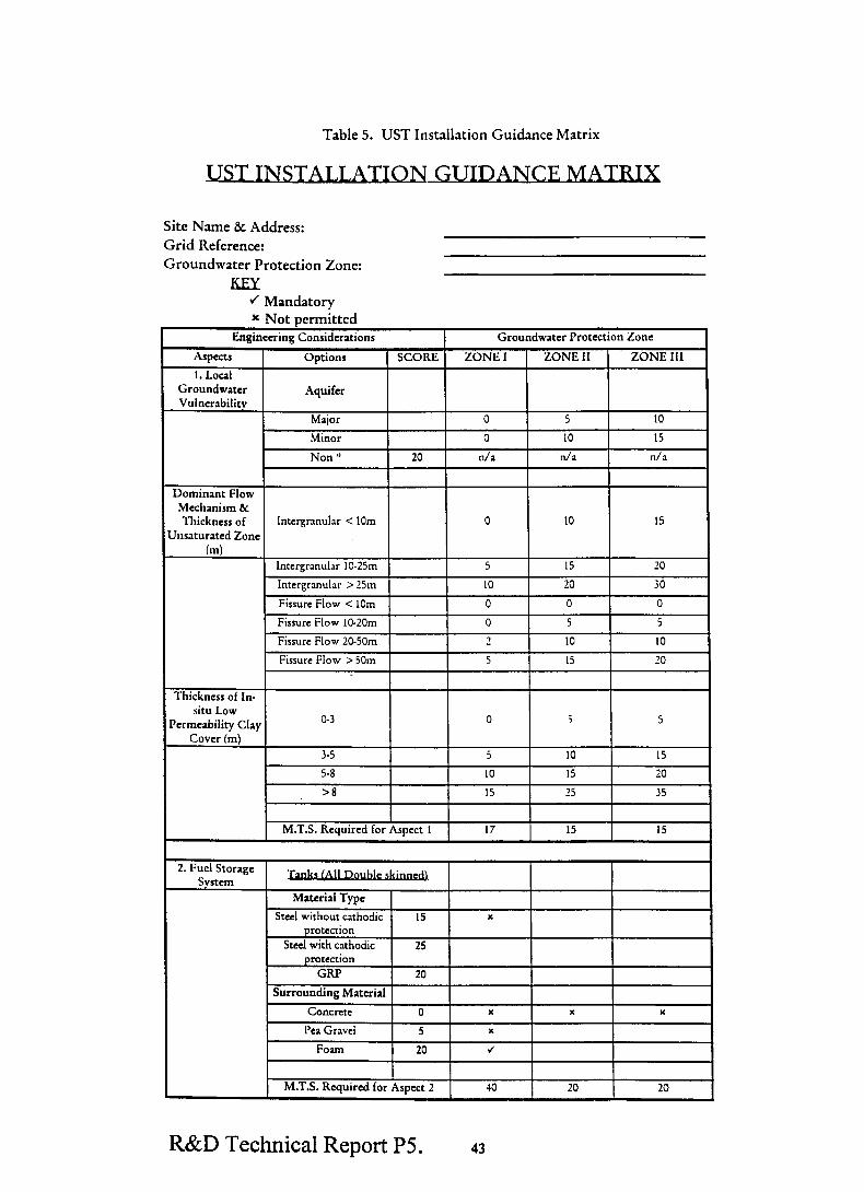
Table 5. UST Installation Guidance Matrix
USTINSTALLATION
Site Name & Address: Grid Reference: Groundwater Protection Zone:
1 R&D Technical Report PS.
J Mandatory
Groundwrtcr
Intergranular < 10m
‘hsaturated Zone
I I M.T.S. Reuuircd for Asocct 1 1 17 15 15
2. Fuel Storage Svrtem
Material Type
Steel without cathodic 15 x protection
Steel with cathodic 25 protection
GRP 20
Surrounding Material
Concrete 0 x x Y
Pea Gravel 5 x
M.T.S. Required for Aspect 2 JO 20 20
43

Aspects
3. Fuel Distribution
Svstem
Engineering Consideratrons Groundwater Protection Zone
Options SCORE ZONE I ZONE II ZONE III
I I I
-I I I I Pressure/Number
Posmve Pressure 20
Sumon I 20 I
Offsets Above Ground 10 J
Offset Fills Below 5 L
Ground
Check valvesat Tank 1 0 x I x x
closure and coalescin
4. Fuel Monitoring
Svstems Tank Monitoring
Tank G~ugmg . 10 4 J J
Contents
R&D Technical Report PS. 44

Engineering Considerations Groundwater Protection Lone I
Aspects
4. Fuel Monitoring
Systems (continued)
Reconclliauon
5. Site Site Spectftc 10 IO IO IO
Maintenance and Contingency Plan for Emergency Emergency Planning
Planning
Traimng of Workforce IO 10 10 IO
Petroleum Officer to be IO IO IO IO
made Aware of the Specific Sensiuvicy of
this Site
M.T.S. Required for Aspect 5 30 30 30
I Total MTS Required 402 290 205
I
Notes: ” - Assumes at least 15 mccres of low permeability formatlon (not drift) over any underlying aquifer.
R - Most developments in SPZ I are precluded by this matrix, unless a large thickness of unsaturated zone and thick overlying clay drift is present. Conversely, SPZ If developments are not permitted if there IS no significant clay cover on a fissured aquifer wtth a very shallow water table. Detailed site specific inrerprerauon of conditions and consideration of the local risk are required in these instances.
This guidance is not intended to be taken as prescriptive, but is taken as minimum standards suitable for high sensitivity sites and to promote national consistency within the Agency. It should not preclude the use of new developments or solutions involving alternative designs, materials or procedures so long as IC can be demonstrated that such alternatives provide an equal or higher level of protection to the aquattc environment.
R&D Technical Report P5. 45

6. APPENDICES
6.1 . .
Furtheron Key papax _
I-IS(G)41 - Pc’ctrol Filling Sratrons: Consrrr~rron and Operation, 1990 (HMSO ISBN 0 11 885449 6).
i-IS(G) 146 - Dispensmg Petrol: Assrgnzng and Controlling the Risk of he and Explosion at Sites whcrc Petrol IS Stored and Dispensed as a Fml, 1996 (HMSO ISBN 0.7176.1048.9).
Draft Document - Specification for Aucomaric Tank Contents Gauges 1995 CEN/TC 221/WG 6&G 5.
Appropriate Material Safety Data Sheets for Fuel (General Hazard Information).
6.2 . .
&t of D- moblm encountered
Site A. Southern England
The site was situated on a main road and had a high turn over of products (one tanker delivery .I day). During construction one of the steel fuel lines was incorrectly threaded at a bend. While this leak was relatively small due to the high throughput the product lost became substantial. Excellent wet stock records were kept although the gauging system had no temperature correction. The records did not indicate a significant loss due to the high product turnover of the site. It was not
until J neighbouring property report odours in their basement that the tanks and lines were tested Jnd the one of the lines failed the test.
Site B. North West England
A large service station site located on a sandy, silty soil experienced ;1 loss of 30 OOOlt due to corrosion of a single skin tank. The loss happened over a short period of time. The site WJS closed for an extended period of time and the remediation costs very significant..
Site C. West Midlands
The site had been occupied as a service station for many years. During redevelopment new r.tnks were installed. The old tanks were to be emptied, cleaned and filled with concrete. BJd construction practise resulted in one tank not been fully emptied, backfilled with loose builders rubble Jnd 3. concrete plug placed in the tank top. This “disused” tank corroded Jnd failed
resulting in a large loss of fuel.
Site D. Northern England
The site was only several years old when a problem was detected. The cause was traced to one of the offset fill pipes. When the pipe was excavated it was found to have been punctured by what appeared to have been a point from a road drill. This puncture hole had been covered with a
makeshift patch which had failed
Site E. Central England
A small service station located on an aquifer used for drinking water abstractions Jnd had J multitude of failures and a tank failure due to corrosion and line fJures. The leaks went undetected until the site was redeveloped. Due to the sensitive nature of the aquifer the EA
R&D Technical Report P5. 46

requested groundwater remediation. This remediation for the site cost the oil company terms of thousmds of pounds.
Site F. Central England
A tank failure (due to corrosion of a steel tank) resulted in the loss of 11 000 litrcs of unleaded petrol into a major aquifer at a site within 15Om of a public water supply river. After investigation of the site itself it was found that the fuel had migrated off site through field drains and had contaminated a large area of adjacent land. Investigation and remedial costs were significant, but residual contamination was left at a sensitive site due to the technical limitations of current clean
up techniques.
Central England
While dipping an ageing steel tank without protection of the tank base, with a brass dipping stick, the base of the tank was ruptured resulting in the loss of about 5 000 litres of leaded petrol. The site is located on a major aquifer and is within the Source Protection Zone II of a public water
supply borehole. Investigation and remedial costs are significant and continuing. The water supply company have been informed and are monitoring their abstraction for pollution. Any
contamination of their source could potentially result in a claim under civil law by the water
undertaker, in addition to criminal liability under the Water Resources Act.
R&D Technical Report PS. 47

. facturers and su&
Listed below are manufacturers and suppliers of forecourt equipment to the petroleum companies and other fuel distributors (THE AGENCY DOES NOT PROMOTE, ENDORSE OR RECOMMEND ANY OF THE PRODUCTS OR SERVICES PROVIDED BY THE COMPANIES OR INDMDUALS LISTED ALPHABETICALLY BELOW. THE LIST IS PROVIDED MERELY AS A POTENTIAL SOURCE OF FURTHER IN-FORMATION SHOULD THE AGENCY OFFICER REQUIRE ADDITIONAL TECHNICAL INFORMATION).
Cookson and Zinn Ltd I I general forecourt products I
Suffolk Steel ranks (double skin) and associated I
R&D Technical Report P5 48

6.3 ers and sutql& (continued)
I Location 1 Product I Rcmarks
Birmingham Steel tank (double skin) and associated
Klargeaer Environmental Engineering Lrd Aylesbury
Knight & Associara Sandy (Beds)
Ledbury Welding & Engineering Lrd Hereford
eqwpmenr
Glass reinforced double skinned tanks
Forecou~ Design
Steel ranks (double skin) and associaed
Suitable for forecoun use
R&D Technical Report PS. 49

6.4 rers and suppliers (continued)
NunC Location
Utility Vault Company Inc. Arizona, USA
\‘eeder Root Richmond, Surrey
W 8r J Risbridger Ltd Redhill
Wefco Group Limited Lint.
Product Remarks
Underground vaults to tanks
Wet stock control, tmk gauging and leak The TLS-350R producr: rmge can supply J complete intcgrxed iuel control JnJ derectlon. leak detection svs[em
Check valves
Steel tanks (double skin) and associxed
R&D Technical Report P5. 50