Guidance for the Management & Use of...
20
Guidance for the Management & Use of Stages and related temporary event structures
Transcript of Guidance for the Management & Use of...

Guidance for the Management & Use of Stages
and related temporary event structures

2
ContentsIntroduction 3
1 Roles & Responsibilities 4
2 Planning and Coordination 6
3 Site Layout 6
4 Traffic Management Plan 7
5 Safety Briefing and Tool Box Talk 7
6 Sub-structure Layout & Free Standing Scaffold Structures 8
7 Boarding and Handrail 9
8 Roof Access and High Level Structures 10
9 Working Ramps & Loading Docks 10
10 Completion of Structure 10
11 Wind Management 11
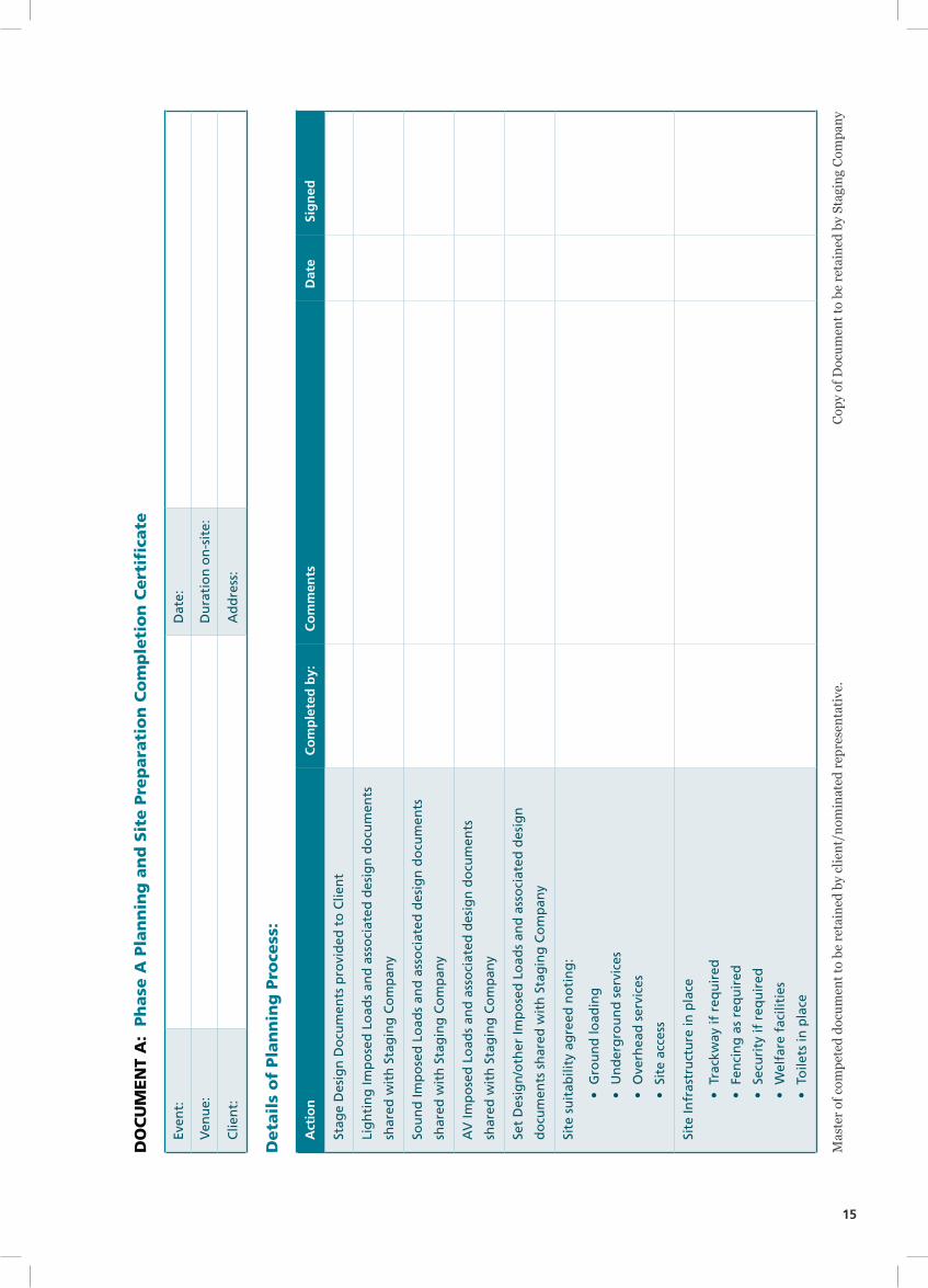
DOCUMENT A: Phase A Planning and Site Preparation Completion Certificate 15
DOCUMENT B: Phase B Stage Construction 16
DOCUMENT C: Phase C Production Services 18

3
IntroductionThis industry code of practice has been written for stages and similar structures and their use at events although much
of what is written can equally be applied to other ‘temporary demountable structures’ (TDS) as the law, with limited
exceptions, does not distinguish between them. These guidelines were developed in consultation between the events
industry and the enforcement agencies, trialled during the summer show season of 2014, and timed to coincide with the
introduction of The Construction Design & Management (CDM 2015) Regulations 2015.
The legal obligations of staging companies are set out in the Health and Safety at Work etc. Act 1974 and its associated
regulations and this guidance seeks neither to replace nor to encompass the full range of obligations for the sector.
Special attention should be directed, but not limited, to the Construction Design and Management Regulations 2015, the
Work at Height Regulations 2005, Lifting Operations and Lifting Equipment Regulations 1998, and the Management
of Health and Safety at Work Regulations 1999. Relevant codes and standards should be adhered to. Advice should be
sought from a range of other sources; these include the HSE www.hse.gov.uk; and the EIF Purple Guide and IStructE
guidance on procurement, design & use of temporary demountable structures.
Under CDM 2015 it is the Client / Event Organiser’s legal responsibility to ensure that a full & sufficient safety file &
safety plan is produced for the event. Responsibility for the monitoring of temporary structures now includes the HSE
on all construction & deconstruction phases as well as the local authority under licensing conditions.
The first step should be discussion with the client regarding identification of parties with whom coordination and
consultation is required to ensure a constructive and positive approach is in place. It is recommended that the TDS
provider keeps records that confirm such contact and liaison has taken place.
The phases of construction are common to all structures but the processes and methods are peculiar to each type of
structure much as the location and environment vary from site to site. This guide does not seek to prescribe systems of
work but management approaches to ensure work is carried out to meet legal obligations. To assist in the management
of the process it has been broken down into four simplified phases as identified below covering from planning to
performance and back through deconstruction.
Planning Coordination
Safe Area
Stage or TDS Construction/
Deconstruction
Production In / Out
Show
A B C D

4
It is important that the process is coordinated and managed. Many events, especially where multiple contractors are
on site, may have formal systems and processes in place that assist staging companies in managing and coordinating
what is required. This industry code looks to identify the minimum requirements for all projects, regardless of size,
required to meet the law in relation, not only to the construction and deconstruction of stages (Phase B), but also the
subsequent installation and removal of all imposed loads such as production, set dressing and branding (Phase C) ready
for show (Phase D). It must be emphasised that variations to the imposed loads from those agreed must be signed off
at the design level.
Responsibility for the integrity of the structure remains with the company who builds it. They have duties in law to
ensure it is fit for purpose, that construction and deconstruction are planned and coordinated, and that it is properly
maintained during use. They have a duty to ensure all imposed loads, such as production, set dressing and branding
do not adversely impact on the integrity of the structure at design level. They also have responsibilities for the health,
safety and welfare of their own staff, and that of all other workers involved in the construction area. It is recommended
that all completion certifications signed at Phase C (production in) are countersigned by the staging company
It is recommended that records, plans and designs are kept on site, and that sign off records are completed for each
phase of construction identified above, and likewise kept on site. Sample completion certificates/hand over documents
are included as part of this guidance to ensure each phase of construction is properly managed and coordinated. Final
responsibility must remain with the client to ensure that these are maintained and that any subsequent changes are
identified and shared with all duty holders.
1 Roles & ResponsibilitiesCDM defines the roles of key ‘Duty Holders’ whose responsibilities are outlined by law. These roles may be combined
and the duties under more than one heading assumed and carried out by a single person or organisation, but everyone
involved in an event supply chain has legal duties and is responsible for informing themselves of those duties and
ensuring clarity about who the key Duty Holders are. This is a very brief précis of the key Duty Holder roles and
their contributions as defined in CDM, but it, and other relevant regulation, should be consulted for more in depth
information.
The Client / Event Organiser:
Holds overall responsibility for managing the project / event and for the appointment of a competent Principal
Contractor (PC) & Principal Designer (PD). NB. The two key roles of PC and PD may sometimes also be carried out
by the client.
Ensuring that:
• Allrelevantinformationispreparedandprovidedtootherdutyholders
• ThePC&PDcarryouttheirduties
• Suitablewelfarefacilitiesareprovidedatalltimesthatworkersareonsite

5
The Principal Designer (PD):
Key duties are liaising with the client and other duty holders. This includes being responsible for planning, managing,
monitoring & coordinating the health & safety of the project, and for the production of an event safety plan for the
purposes of identifying, eliminating or controlling foreseeable risks. This role may be allocated to or assumed by an
individual or organisation, or may be carried out by the client. The duties may also be assumed by a team of people
or organisations, which would include anyone providing production design information such as rigging loads etc.
Ensuring that:
• Designerscarryouttheirduties
• Relevantinformationispreparedandprovidedtootherdutyholders
• LiaisewiththePrincipalContactor(PC),tohelpintheplanning,management,monitoringand
coordinationoftemporarystructures,includingonsitesignoffpaperworkasdetailedinthisguide
Principal Contractor (PC)
Key duties are liaising with the Client & PD, and preparing the TDS management plan. Responsible for planning,
managing, monitoring and coordinating all phases of the build and use of temporary structures on site, and for organising
co-operation between contractors and coordinating their work. This role may be allocated to or assumed by an individual,
such as a production manager or and organisation, a production company, or may be carried out by the client.
Ensuring that:
• Suitablesiteinductionsareprovided
• Reasonablestepsaretakentopreventunauthorisedaccess
• Workersareconsultedandengagedinsecuringtheirhealthandsafety
• Welfarefacilitiesareinplace
Contractors
Key responsibilities are the planning, managing and monitoring of construction and deconstruction of all temporary
structures under their control so that it is carried out without risks to health and safety.
Ensuring that:
• TheTDSdesignerpreparesdrawingsandagreesallweightloadingsofproposedtemporarystructures
• LiaisingwiththePCtocoordinateactivitieswiththoseothercontractors
• ComplyingwithdirectionsgiventothembythePCorPD
Workers
All those engaged in the construction and deconstruction of temporary structures must:
• Beconsultedaboutmatterswhichaffecttheirhealthandsafety
• Takecareoftheirownhealthandsafetyandthatofotherswhomaybeaffectedbytheiractions
• Reportanythingtheyseewhichislikelytoendangereithertheirownorothers’healthandsafety
• Cooperatewiththeiremployer,fellowworkers,contractorsandotherdutyholders

6
2 Planning and Coordination• Clearidentificationofrolesandresponsibilitiesneedstobeagreedinadvance
• Designdocumentationincludingdrawings,certificates,andcalculationsofloadings,windactionplans,
methodstatementsandriskassessmentsshowingtheactualstructureplannedshouldbeshared.
Anysubsequentvariationtodesignmustbesupportedbynew/amendeddocumentation
• Competencyisakeyfactorwhenappointingcontractorstosupportthesafemanagementofstructures.
Aprocurementprocessthatidentifiescontractorswithappropriateexperience,trainingandresources
tosupportsafedeliveryisrecommended.Thisextendstostagecrewandlocalcrewthatmaybeused
toassistinconstruction/deconstruction.Itistheresponsibilityoftheclienttoappointcompetent
contractors.Itistheresponsibilityofthecontractortoensuresub-contractorsarecompetent
• Consultationmusttakeplacewithusersofthestructuresuchasproductiontoensureimposedloads,
supportedbydesigndrawingsanddetailedcalculations,areidentifiedandagreedinadvancesoasto
ensuretheoverallintegrityofthestructureisnotcompromised
• Detailsofgroundconditions,suitabilityfortheplannedloads,andidentificationofoverhead
orundergroundservicesshouldalsobeprovidedinwritingtotheTDScontractor.Itremainsthe
responsibilityoftheclient,unlessspecificallyidentifiedandagreedinwriting,toprovidesuch
information
• Anagreedprogrammeforexchangeofdocuments,timingsofarrival,constructionanddeconstruction
schedule,inspectionsandsignoffshouldbeinplace
3 Site LayoutIt is the responsibility of the client, and or their appointed PD & PC, to provide and maintain safe working areas, and to
provide for the welfare of all contractors they engage.
• Welfarefacilitiesforstaffandcontractorsincludingtoilets,waterandsomeformofsheltermustbe
providedbytheclient
• Theproposedworkingareasneedtobesecuredfromthegeneralpublicandpreparedforthearrivalof
trucks,useofplant,etc
• Workingareasforthestageconstructionteammayrequireseparationfromothersiteactivitiesandworkers
• Ifthesiteisdeemedtobeahigh-riskareatheninstallationoffencingandmanagementsystemsto
controlaccessarerequiredandsecuritystaffmayneedtobeconsidered.(Aconstructionareamaybe
deemedtobehighriskwheremultiplecontractorsareonsiteatthesametimeand/ormembersofthe
publichaveaccesstothesite)
• Ifthesiteisconsideredtobelowrisk,temporarybarrierorpinandtapemaybeused.(Aconstruction
areamaybedeemedtobelowriskwheretheareaisclosedtothepublicandtherearelimited
contractorsonsitethatdonotimpingeoneachother)

7
4 Traffic Management Plan The staging traffic management plan needs to be established within, and as part of, creating a safe working area. This
is not just about getting the trucks to site in the right order, but ensuring their unloading is planned and managed to
ensure safety. The TM plan may include:-
• Plantmovement,loadingandunloadingtrucksandmovingequipmenttostage,plannedtoavoid
reversingwhereverpossiblebuttoincludeabanksmanwhennecessary
• Pedestrianworkeraccesstoensureseparationofvehiclesandpeople
• Truckmovementandunloadingarea
• Safeworkingareasforstaff
• Stillagelaydownarea
• Equipmentaccessroute(s)tobuildlocation
• Proofofcompetencytodriveplant/equipment
5 Safety Briefing and Tool Box TalkThe aim of this is to ensure that safe working practices are established on site.
• Attendanceatafullsitesafetybriefing(whichistheresponsibilityoftheclientortheirnominatedPC)is
requiredforeverycontractorandeveryproject.Thisbriefingmustnotesite-specifichazardsthatmaybe
presentandhighlightthemforcontractors
• Coordinationofareaoverlapsordifferentcontractor’ssiterulesandsafeworkingmethodsmustbe
consideredbytheclient,ortheirnominatedPD
• Toolboxtalksshouldbecarriedoutforeachmajoractivityatthestartofeachworkperiodbythe
contractordeliveringthestructureandinclude:
• Discussionoftheworkrequiredforthedayaheadandsafetymessagesfromsitesafetybriefing
• Reviewandunderstandingofbuildmethodstatementandriskassessmentandhowtheyapply
tothespecifictaskbeingundertakeninthatperiod,ensuringthatallsafetyregulationssuchas
workatheightandproperuseofPPEareadheredto
• Assessmentofwindconditions,anditsimpactonconstructionandmethodsofwork
• Detaileddrawingsofthetemporarystructure/sforthatsite(see1PlanningandCoordinationabove)
mustbeavailableonsitepriortocommencementandthroughouttheproject

8
6 Sub-structure Layout & Free Standing Scaffold Structures
The aim of this section is to identify safe practices around construction of sub-structures involved in the building of
many types of stage and construction of free-standing scaffold structures such as FOH towers, spot towers, viewing
platforms, etc. The legal requirement is set out in the chart below based on HSE guidance - A Brief Guide to Working at
Height Regulations 2005 as amended (www.hse.gov.uk)
• Wherepossiblealllowlevelsub-structuresupto1.75mshouldbebuiltfromthegroundwiththeuse
ofraisedstepplatformsandwalkboardsacrossthescaffoldstructuretoaidtheconstructionwhere
necessary.Anyconstructionabove0.6mmustbeaccessedviatemporaryladdersorsteppedaccess
• Intheeventofinstallingequipmentabove1.75m,asuitableandsufficientsystemmustbeinplacewhich
sofarasreasonablypracticablewillpreventfallsthatmayleadtoinjury.Thismayinclude,forexample,
theuseofMEWP,fixedrestraint/workpositioningrestraints,orothersuitablemeansofpreventingfalls;
or,forexample,nettingsystemstominimiseconsequenceifafalloccurs
• Clippingontoanincompletestructureasameansoffallpreventionmaynotprovideanadequatemeans
offallprotection.Freeclimbingonthestructureisprohibitedatalltimesanderectionmustproceedon
thebasisthataccessisachievedthroughtheuseoftemporaryboardingthathasaminimumwidthof
0.5mwithladderaccess,andtheinstallationofhandrailsassoonasisreasonablypracticable
DutyHolders(Client&Designers)must
Avoidworkingatheightwheretheycan
Useworkequipmentorothermeasures
topreventfallswheretheycannotavoid
workingatheight;and
Wheretheycannoteliminatetherisk
ofafall,useworkequipmentorother
measurestominimisethedistancesor
consequenceofafallshouldoneoccur

9
7 Boarding and HandrailWorkers need to be protected from injury caused by falls from height. To meet this standard, contractors should ensure:
• Asafemeansoflayingtheinitialboardsinordertoachieveasafeworkingplatform
• Temporaryladderaccessshouldbeinstalledassoonaspossible
• Forinstallationoftheremainderofthedeckingsystem,asuitable&sufficientmethodmustbe
establishedofminimisingtheriskoffallsfromheight,sofarasisreasonablypracticable,whichmay
includetheuseoffixedrestraintorworkpositioningrestraint,fallpreventionnettingorothersuitable
meansofpreventingfallsfromheight
• Edgeprotectionmustbeestablishedasthedeckingproceeds
• Ondeckingofindependentstructureswithaworkingareaabovehead-height,suitablemeasuresmust
beinstalledtopreventequipmentfallingfromtheplatform.Thismayconsistofraisedupstands,toe-
boards,solidhandrails,fixedsheetingornettingasappropriate.
• Permanentaccessstepsmustbeinstalledassoonaspossible
• Wherereasonablypracticableforedgesofthedeckedstagethatarenotprotectedbypermanentedge
protectionthereneedstobesuitabletemporaryprotectionoftheleadingedge.Leadingedgeprotectionfor
workersneedsspecificconsiderationandmust,sofarasisreasonablypracticable,beinplaceforPhaseB
• Allunprotectedleadingedgesshouldbemarkedbyawhitelineattheedgepoint,andalsoavisible
warningline,suchasorangeoryellow,0.6mbackfromtheedgepointorothersuitablewarningsystem
• Onlowleveldecking,upto1.75m,atemporarystraplinemaybeinstalled1mfromtheleading
edgestoactasaproximitywarning
• Thismayalsobeusedonhigherleveldeckingwherethereisalowerthrustorcameratrack
platforminstalledinfrontofthemainplatform
• Onhigherleveldeckingabove1.75mwherenointermediatedeckingisusedsuitableload
bearingedgeprotectionmustbeinuse
• Planningofthesesystemsmustaccountforaccessfordeliveryofgoodstotheplatform
• Itisunderstoodthatcertainroofconstructionsequencesandproductioninstallationsmayrequirethe
temporaryremovalofthesesystemsduringphasesB&C,buttheyaretobereinstatedassoonasis
reasonablypracticabletoregainasafeworkingarea
• Itisrecommendedthatthetemporaryedgeprotectionsystemsbeleftinplaceuntilallinstallation
operationsonthestagearecomplete,whichisphaseD
• Allaccessholesleftinthedeckorplatformduringthebuildprocessmustbecoveredorprovidedwith
similarbarrierstothefrontedgetypetopreventfallsduringphasesB,CandD

10
8 Roof Access and High Level StructuresSystems should be designed to eliminate high-level work wherever possible (see 5. Sub structure layout, above). It
is recognised that in many stage designs this is not currently possible and therefore engineering solutions and the
following guidelines should be considered including:
• Freeclimbingofthestructureandroofisprohibitedatalltimes
• Accessequipmentmustbeprovidedwhereverpossible
• Twintaillanyards,fallpreventionorfallarrestsystemsmustbeusedonallclimbingoperations
• Inaworkposition,afixedrestraintmustbeused
• Afallpreventionorfallarrestsystemmustbeinplacewhenaccessingandworkingonstageroofs
• FallPreventionlines/barriersshouldbedesignedtotakeassociatedloads,andthattheyshouldbefixed
tothestructurethatisstrongenoughtotaketheforces
• Suitablemeasuresshouldbetakentokeeptoolssafefromfallsfromheight
• InaccordancewiththeindustryAccessEquipmentRegulationsitisadvisedthatthereshouldbeno
climbingofanystructurewhenwindisgustingabovespeedsof12(27mph)metrespersecond,subjectto
onsiteriskassessment
9 Working Ramps & Loading Docks• Allinclinedrampsmustbecoveredinasuitablenon-slipmaterialtopreventslip&fallinjuries
• Allloadingdockleadingedgesmusthaveawhitelineedgemarkerandadistinctivewarningline0.6m
backfromtheedgepoint
• Allrampgradientsmustbesuitablenottocauseanyhazardswhilstloadingproduction
• Allrampslongerthan8.0mmusthavealandingstagebuiltintothedesign(Wherepracticable).
• Allrampsmusthaveadequatehandrails,suitableforcrewpullingagainstthemwhilstmoving
equipmentonwheels
10 Completion of Structure• Thestructureshouldnotbeclassedascompleteuntilallplannedimposedloadshavebeeninstalledand
signedoff.SamplecompletioncertificatesareappendedtothisGuide
• Itisrecommendedthatacompletioncertificateshouldnowincludenotonlythesafehand-overofthe
structureasfitforpurpose,butalsoindividualproductioncontractorsignaturesconfirmingthatimposed
loadshavebeeninstalledinasafemanner,andhavebeeninstalledtoagreeddesignsandweightloadings
• Thereforeacompletioncertificate(PhaseB)isrequiredattheendoftheinitialconstructionphaseto
indicatethestructureissafeforproductioncontractorstobegininstallation
• Furthercompletioncertificates(PhaseC)arerequiredforeachloadtypethathasbeenappliedtothe
structure.Thesecertificatesshouldbesignedbybothstructureandproduction(i.e.lighting,sound,
video,set,etc)representatives
• Onlyonceallcertificatesareinthepossessionoftheclientornominatedrepresentative,willsound-
checks,rehearsalsorshowsbepermittedtocommence(PhaseD)
• Itisrecognisedthatinsomeshowssuchasfestivalstherewillbemultipleartistsaccessingthestagewith
varyingproduction,itmustbeemphasisedthatanymajorchangestotheimposedloadsonthestructure
mustbeagreedinadvancewiththestructuredesigner
• Itmustbere-emphasisedherethatfinalresponsibilitymustremainwiththeclientortheirnominated
representativetoensurethattheaboveiscoordinatedandmaintained
• Proposedtemplatesfortheseprocessesareenclosed

11
11 Wind ManagementThis guidance is given not only for the management of stages and similar structures but also to be taken into account as a site-wide guide to wind management for the safety of the public, performers & all other workers at the event. Decisions regarding the safe running of an event need to be taken well in advance of reaching the operational wind loading capacities of the stage itself, specifically it should be noted that other structures may have much lower tolerances.
The wind reference chart below will help to clarify the relationship between various wind measurements and it must be noted that 12 metres per second is a strongwind and site conditions may start to become hazardous at this speed. Each site has its own topography and local conditions and response to winds. The wind management plan must therefore be adjusted to include this data.
Wind Reference Chart
BeaufortScale&Description AverageSpeedat10metresaboveground.
0 Calm MetresPerSecond MilesPerHour
1-3 Light Breeze 0.3 to 5.4 m/s 0.7 to 12.2 Mph
4 Moderate Breeze 5.5 to 7.9 m/s 12.3 to 17.8 Mph
5 Fresh Breeze 8.0 to 10.7 m/s 17.9 to 24.0 Mph
6 Strong Wind 10.8 to 13.8 m/s 24.1 to 31.0 Mph
7 Nr Gale Force 13.9 to 17.1 m/s 31.1 to 38.3 Mph
8 Gale Force 17.2 to 20.7 m/s 38.4 to 46.4 Mph
9 Strong Gale Force 20.8 to 24.4 m/s 46.6 to 54.7 Mph
10 Storm Force 24.5 to 28.4 m/s 54.8 to 63.6 Mph
• Carefulconsiderationmustbegiventowindmanagementthroughoutallphases.Attheplanningstage,
PhaseA,adviceshouldbegiventotheeventorganiserregardingsitelayout,takingintoaccountstage
orientationinrelationtotopographicallocation.Afullsiteriskassessmentshouldbedonetoensurethat
factorssuchasconstructiononheadlands,onthecoastorinvalleyswherewindcanfunnelaretaken
intoaccount,andsuitabledesignchangesareimplementedwherenecessary
• IStructEguidanceregardingtemporarystructuresisthattheyshouldbedesignedtowithstandtheloads
createdbywindgustsof25metrespersecond(approximately55mph).Theguidancedoeshowever
allowfortheremovalofsheeting.Manystructureshaveamuchlowertolerancewhenfullysheetedand
eventorganisersshouldbeawareofthiswhenconstructingwindmanagementplans
• Inviewofthispotentialconfusion,HSEhavestronglyrecommendedthatduringphasesC&D,roof
sheetsshouldnotberemovedshouldgustingbecomehazardous,asscreens,stagesets,drapesand
lightingrigsinsidethestagestructure,exposedtothewind,becomedynamicloadsratherthanstatic
andthemselvesputunduestrainonthestructure.Somestagedesignsneedlowlevelwallsheetingto
beremovedatcertainwindspeedsandtherequirementsforthisandthepotentialissuesthatmayarise
needtobeclearlydocumentedinadvanceoftheevent

12
The following procedures take into account all of the event production elements rather than just the structure itself.
• Ananemometershouldbeinstalledassoonasisreasonablypracticableandmustbeconstantly
monitoredwhenconditionsarelikelytocauseahazard
• Eachstructureshouldhaveitsownspecificwindactionplanthatcanbeintegratedintotheoverallevent
safetyplantakingintoaccountsitespecifictopographyandseasonality.Theeventsafetyplanshould
identifywhatactionsshouldbetaken,whenandbywhominrelationtoeachspecificstructure
• Thereshouldbemonitoringofweatherforecastsfortheareaatalltimesfrombeginningofconstruction
untildeconstructioniscomplete
• DuringPhasesB&C,theuseofaccessequipmentorroofclimbingmustceaseifgustingbecomes
continuousabove12metrespersecond(27MPH)basedonindustrystandardaccessequipment
manufacturersrecommendedmaximumoperationalwindspeed
The following action chart is a guide to operational monitoring throughout the event.
WindSpeedMetres/sec
MonitoringInterval
ActionLevel
Action
Below 6 8 hourly Regular Weather Forecast Review.
7 - 11 Hourly Regular on Site Assessment
12 - 18 30 minsPrepare to halt erection operations until safe working conditions have resumed. During Phase D (Show) it is likely that Show Stop will occur in this range due to factors other than TDS safety
18 - 22 15 mins 2Site safety meeting and risk assessment.
Prepare for full site evacuation
Over 22 Constant Site evacuation procedure to be implemented
PLANNING
Site topography & prevailing
winds
NORMAL CONDITIONS
Monitor Forecast Review
ACTION LEVEL 1
Alert Risk Assess
ACTION LEVEL 2
Enhanced action
response plan
May involve event
cancellation
ACTION LEVEL 3STOP!
1
2
3

13
At Action Level 1:
When monitoring registers a gust wind speed in excess of 12 metres per second, in conjunction with an increasing
general trend of recorded high wind speeds, then subject to risk assessment, all staff involved with the installation/
erection of the structure(s) should be put on alert that action may be required to delay the erection process until safe
working conditions have returned. This process should be adopted into the overall site wind management plan.
At Action Level 2:
It is recommended as safe practice for a site safety meeting to be convened to assess the overall site conditions when
monitoring registers a gust wind speed in excess of 15 metres per second in conjunction with an increasing general
trend of recorded high wind speeds. (This can be varied subject to onsite risk assessment.) This should be adopted
into the overall event safety plan and preparations should be made regarding show stop procedure and full or partial
evacuation of the site should wind speeds increase making site conditions unsafe.
At Action Level 3:
When monitoring registers a gust wind speed in excess of 22 metres per second in conjunction with an increasing
general trend of high recorded wind speeds, and determined by risk assessment:
• Siteevacuationmayhavetobeimplemented
• Asafetymeetingmustbecalledtoidentifysubsequentactionsuchastheloweringofproduction
• Thestructuremustimmediatelybecomeahardhatareaforessentialpersonnelonly
• Thestagemaybeevacuatedandasafeperimeterimposedaroundalltemporarystructures
• Beforeperformancesresume,ordeconstructionbegins,theremustbeastructuralinspectionandnewsignoff.
Understanding the effect of wind on structures:
It is important to recognise that it is wind pressure on a structure that poses an issue not merely wind speeds
themselves. The relationship between pressure and wind is not linear. The applied pressure is proportional to the
square of the wind speed.
For example: An increase in wind speed from 12 metres per second to 17 metres per second will approximately double
the pressure on the structure. Between 12 metres per second & 24 metres per second, pressure on the structure
approximately quadruples. See table and graph.

14
Surface Pressure Chart
WindSpeedMetresPerSecond WindSpeedMilesPerHour SurfacePressureInkN/m2
12 m/s 26.88 Mph 0.088
13 m/s 29.12 Mph 0.104
14 m/s 31.36 Mph 0.120
15 m/s 33.6 Mph 0.138
16 m/s 35.84 Mph 0.157
17 m/s 38.08 Mph 0.177
18 m/s 40.32 Mph 0.199
19 m/s 42.56 Mph 0.221
20 m/s 44.8 Mph 0.245
21 m/s 47.04 Mph 0.270
22 m/s 49.28 Mph 0.297
23 m/s 51.52 Mph 0.324
24 m/s 53.76 Mph 0.353
25 m/s 56 Mph 0.383
1050 15 20 25 30 35 40
0.400
0.600
0.800
0.200
0.000
Surface Pressure to Wind Speed
Wind Speed (metres per second)
Dyn
amic
Pre
ssu
re (
kN/m
2)
DO
CU
MEN
T A
: P
hase
A P
lan
nin
g a
nd
Sit
e P
rep
ara
tio
n C
om
ple
tio
n C
ert
ifi c
ate
Even
t:D
ate:
Ven
ue:
Du
rati
on
on
-sit
e:
Clie
nt:
Ad
dre
ss:
Deta
ils
of
Pla
nn
ing
Pro
cess
:
Action
Completedby:
Commen
tsDate
Signed
Stag
e D
esig
n D
ocu
men
ts p
rovi
ded
to
Clie
nt
Lig
hti
ng
Imp
ose
d L
oad
s an
d a
sso
ciat
ed d
esig
n d
ocu
men
ts
shar
ed w
ith
Sta
gin
g C
om
pan
y
Sou
nd
Imp
ose
d L
oad
s an
d a
sso
ciat
ed d
esig
n d
ocu
men
ts
shar
ed w
ith
Sta
gin
g C
om
pan
y
AV
Imp
ose
d L
oad
s an
d a
sso
ciat
ed d
esig
n d
ocu
men
ts
shar
ed w
ith
Sta
gin
g C
om
pan
y
Set
Des
ign
/oth
er Im
po
sed
Lo
ads
and
ass
oci
ated
des
ign
do
cum
ents
sh
ared
wit
h S
tag
ing
Co
mp
any
Site
su
itab
ility
ag
reed
no
tin
g:
• G
rou
nd
load
ing
• U
nd
erg
rou
nd
ser
vice
s
• O
verh
ead
ser
vice
s
• S
ite
acce
ss
Site
Infr
astr
uct
ure
in p
lace
• T
rack
way
if r
equ
ired
• F
enci
ng
as
req
uir
ed
• S
ecu
rity
if r
equ
ired
• W
elfa
re f
acili
ties
• T
oile
ts in
pla
ce
Mas
ter
of c
ompe
ted
docu
men
t to
be r
etai
ned
by c
lient
/nom
inat
ed r
epre
sent
ativ
e.
Cop
y of
Doc
umen
t to
be r
etai
ned
by S
tagi
ng C
ompa
ny
15
DO
CU
MEN
T A
: P
hase
A P
lan
nin
g a
nd
Sit
e P
rep
ara
tio
n C
om
ple
tio
n C
ert
ifi c
ate
Even
t:D
ate:
Ven
ue:
Du
rati
on
on
-sit
e:
Clie
nt:
Ad
dre
ss:
Deta
ils
of
Pla
nn
ing
Pro
cess
:
Action
Completedby:
Commen
tsDate
Signed
Stag
e D
esig
n D
ocu
men
ts p
rovi
ded
to
Clie
nt
Lig
hti
ng
Imp
ose
d L
oad
s an
d a
sso
ciat
ed d
esig
n d
ocu
men
ts
shar
ed w
ith
Sta
gin
g C
om
pan
y
Sou
nd
Imp
ose
d L
oad
s an
d a
sso
ciat
ed d
esig
n d
ocu
men
ts
shar
ed w
ith
Sta
gin
g C
om
pan
y
AV
Imp
ose
d L
oad
s an
d a
sso
ciat
ed d
esig
n d
ocu
men
ts
shar
ed w
ith
Sta
gin
g C
om
pan
y
Set
Des
ign
/oth
er Im
po
sed
Lo
ads
and
ass
oci
ated
des
ign
do
cum
ents
sh
ared
wit
h S
tag
ing
Co
mp
any
Site
su
itab
ility
ag
reed
no
tin
g:
• G
rou
nd
load
ing
• U
nd
erg
rou
nd
ser
vice
s
• O
verh
ead
ser
vice
s
• S
ite
acce
ss
Site
Infr
astr
uct
ure
in p
lace
• T
rack
way
if r
equ
ired
• F
enci
ng
as
req
uir
ed
• S
ecu
rity
if r
equ
ired
• W
elfa
re f
acili
ties
• T
oile
ts in
pla
ce
Mas
ter
of c
ompe
ted
docu
men
t to
be r
etai
ned
by c
lient
/nom
inat
ed r
epre
sent
ativ
e.
Cop
y of
Doc
umen
t to
be r
etai
ned
by S
tagi
ng C
ompa
ny

16
DO
CU
MEN
T B
: P
hase
B S
tag
e C
on
stru
ctio
n
Even
t:D
ate:
Ven
ue:
Du
rati
on
on
-sit
e:
Clie
nt:
Ad
dre
ss:
The
follo
win
g se
ctio
ns a
re to
be
com
plet
ed b
y a
duly
aut
hori
sed
sign
ator
y of
the
stag
ing
cont
ract
or:
Deta
ils
of
Str
uct
ure
(s):
StructureTyp
e:Su
pervisedby:
PurposeForWhichTheStructure(s)intended
:
I h
ereb
y ce
rtif
y th
at t
he
stru
ctu
re(s
) ar
e er
ecte
d c
orr
ectl
y in
acc
ord
ance
wit
h t
he
des
ign
dra
win
gs
tech
nic
al s
pec
ifi c
atio
ns
and
met
ho
d s
tate
men
ts i
den
tifi
ed i
n
Do
cum
ent
A, t
hat
all
req
uir
ed s
afet
y m
easu
res
are
in p
lace
an
d t
hat
th
e st
ruct
ure
(s)
are
fi t
for
pu
rpo
se a
s id
enti
fi ed
ab
ove
. I
furt
her
cer
tify
th
at I
am a
n a
uth
ori
sed
&
com
pet
ent
rep
rese
nta
tive
of
the
stag
ing
co
mp
any
nam
ed b
elo
w.
……
……
……
……
……
……
……
……
......
......
......
......
......
......
......
......
......
......
......
.
Dat
e:
Tim
e:
Sig
n:
Prin
t N
ame
& P
osi
tio
n
DO
CU
MEN
T B
(co
nt)
:D
eta
ils
Of
An
y A
pp
roved
Vari
ati
on
s to
Sta
ge C
on
stru
ctio
n f
rom
Desi
gn
Dra
win
gs
/ as
speci
fi ed
in
Do
cum
en
t A
.
Iden
tifyAnyLimitationsOfUsein
lightofap
prove
dvariation(s)
I h
ereb
y ce
rtif
y th
at t
he
follo
win
g m
od
ifi c
atio
ns
hav
e b
een
mad
e to
th
e st
ruct
ure
(s)
du
rin
g i
nst
alla
tio
n s
tric
tly
in c
on
sult
atio
n w
ith
th
e co
mp
any’
s d
esig
n e
ng
inee
rs.
Thes
e m
od
ifi c
atio
ns
hav
e b
een
ap
pro
ved
by
the
des
ign
en
gin
eers
, an
d t
he
fi n
al s
tru
ctu
re a
sses
sed
by
a co
mp
eten
t p
erso
n o
nsi
te.
Mo
difi
cat
ion
s d
o n
ot
affe
ct t
he
safe
ty
of
the
stru
ctu
re o
r sy
stem
or
the
pu
rpo
se in
ten
ded
or
pla
ce li
mit
atio
ns
or
rest
rict
ion
s o
n it
s u
se u
nle
ss d
etai
led
bel
ow
:
Modification
Limitationsonuse
Date
Authorisedby(signature&print)
AD
ate:
Tim
e:
Sig
n:
Prin
t:
BD
ate:
Tim
e:
Sig
n:
Prin
t:
CD
ate:
Tim
e:
Sig
n:
Prin
t:
DD
ate:
Tim
e:
Sig
n:
Prin
t:
ED
ate:
Tim
e:
Sig
n:
Prin
t:
Mas
ter
of c
ompe
ted
docu
men
t to
be r
etai
ned
by c
lient
/nom
inat
ed r
epre
sent
ativ
e.
Cop
y of
Doc
umen
t to
be r
etai
ned
by S
tagi
ng C
ompa
ny

17
DO
CU
MEN
T B
(co
nt)
:D
eta
ils
Of
An
y A
pp
roved
Vari
ati
on
s to
Sta
ge C
on
stru
ctio
n f
rom
Desi
gn
Dra
win
gs
/ as
speci
fi ed
in
Do
cum
en
t A
.
Iden
tifyAnyLimitationsOfUsein
lightofap
prove
dvariation(s)
I h
ereb
y ce
rtif
y th
at t
he
follo
win
g m
od
ifi c
atio
ns
hav
e b
een
mad
e to
th
e st
ruct
ure
(s)
du
rin
g i
nst
alla
tio
n s
tric
tly
in c
on
sult
atio
n w
ith
th
e co
mp
any’
s d
esig
n e
ng
inee
rs.
Thes
e m
od
ifi c
atio
ns
hav
e b
een
ap
pro
ved
by
the
des
ign
en
gin
eers
, an
d t
he
fi n
al s
tru
ctu
re a
sses
sed
by
a co
mp
eten
t p
erso
n o
nsi
te.
Mo
difi
cat
ion
s d
o n
ot
affe
ct t
he
safe
ty
of
the
stru
ctu
re o
r sy
stem
or
the
pu
rpo
se in
ten
ded
or
pla
ce li
mit
atio
ns
or
rest
rict
ion
s o
n it
s u
se u
nle
ss d
etai
led
bel
ow
:
Modification
Limitationsonuse
Date
Authorisedby(signature&print)
AD
ate:
Tim
e:
Sig
n:
Prin
t:
BD
ate:
Tim
e:
Sig
n:
Prin
t:
CD
ate:
Tim
e:
Sig
n:
Prin
t:
DD
ate:
Tim
e:
Sig
n:
Prin
t:
ED
ate:
Tim
e:
Sig
n:
Prin
t:
Mas
ter
of c
ompe
ted
docu
men
t to
be r
etai
ned
by c
lient
/nom
inat
ed r
epre
sent
ativ
e.
Cop
y of
Doc
umen
t to
be r
etai
ned
by S
tagi
ng C
ompa
ny

18
DO
CU
MEN
T C
: P
hase
C P
rod
uct
ion
Serv
ices
(to
be c
om
ple
ted
by e
ach
co
ntr
act
or
inst
all
ing
im
po
sed
lo
ad
s an
d c
ou
nte
rsig
ned
b
y s
tag
ing
rep
rese
nta
tive)
Even
t:D
ate:
Ven
ue:
Du
rati
on
on
-sit
e:
Clie
nt:
Ad
dre
ss:
The
follo
win
g se
ctio
ns a
re to
be
com
plet
ed b
y a
duly
aut
hori
sed
sign
ator
y of
the
prod
ucti
on c
ontr
acto
r:
Deta
ils
of
Imp
ose
d l
oad
on
Str
uct
ure
(s)
iden
tifi
ed
in
Do
cum
en
t A
:
Impose
dLoad
Typ
e:Su
pervisedby:
PurposeForWhichTheIm
posedLoad
(s)intended
:
I h
ereb
y ce
rtif
y th
at t
he
imp
ose
d l
oad
s d
etai
led
ab
ove
hav
e b
een
in
stal
led
in a
cco
rdan
ce w
ith
ap
pro
ved
dra
win
gs
and
wei
gh
t lo
adin
gs
iden
tifi
ed i
n
Do
cum
ent
A a
nd
th
at t
hes
e in
stal
lati
on
s h
ave
bee
n a
sses
sed
on
site
by
a
com
pet
ent
per
son
& d
o n
ot
affe
ct t
he
safe
ty o
f th
e st
ruct
ure
(s)
or
syst
em(s
)
iden
tifi
ed i
n D
ocu
men
t B
. I
fu
rth
er c
erti
fy t
hat
I a
m a
n a
uth
ori
sed
an
d
com
pet
ent
rep
rese
nta
tive
of
the
pro
du
ctio
n c
om
pan
y n
amed
bel
ow
.
……
……
……
……
……
……
……
……
......
......
......
......
......
......
......
......
......
......
......
Dat
e:
Tim
e:
Sig
n:
Prin
t N
ame
& P
osi
tio
n
DO
CU
MEN
T C
(co
nt)
:D
eta
ils
Of
An
y A
pp
roved
Vari
ati
on
s in
Im
po
sed
Lo
ad
s fr
om
Desi
gn
Dra
win
gs
/ as
speci
fi ed
in
Do
cum
en
t A
.
Iden
tifyAnyLimitationsOfUsein
lightofap
prove
dvariation(s)
I h
ereb
y ce
rtif
y th
at t
he
follo
win
g m
od
ifi c
atio
ns
hav
e b
een
mad
e to
th
e st
ruct
ure
(s)
du
rin
g i
nst
alla
tio
n s
tric
tly
in c
on
sult
atio
n w
ith
th
e co
mp
any’
s d
esig
n e
ng
inee
rs.
Thes
e m
od
ifi c
atio
ns
hav
e b
een
ap
pro
ved
by
the
des
ign
en
gin
eers
, an
d t
he
fi n
al s
tru
ctu
re a
sses
sed
by
a co
mp
eten
t p
erso
n o
nsi
te.
Mo
difi
cat
ion
s d
o n
ot
affe
ct t
he
safe
ty
of
the
stru
ctu
re o
r sy
stem
or
the
pu
rpo
se in
ten
ded
or
pla
ce li
mit
atio
ns
or
rest
rict
ion
s o
n it
s u
se u
nle
ss d
etai
led
bel
ow
:
Modification
Limitationsonuse
Date
Authorisedby(signature&print)
AD
ate:
Tim
e:
Sig
n:
Prin
t:
BD
ate:
Tim
e:
Sig
n:
Prin
t:
CD
ate:
Tim
e:
Sig
n:
Prin
t:
DD
ate:
Tim
e:
Sig
n:
Prin
t:
ED
ate:
Tim
e:
Sig
n:
Prin
t:
Mas
ter
of c
ompe
ted
docu
men
t to
be r
etai
ned
by c
lient
/nom
inat
ed r
epre
sent
ativ
e.
Cop
y of
Doc
umen
t to
be r
etai
ned
by S
tagi
ng C
ompa
ny

19
DO
CU
MEN
T C
(co
nt)
:D
eta
ils
Of
An
y A
pp
roved
Vari
ati
on
s in
Im
po
sed
Lo
ad
s fr
om
Desi
gn
Dra
win
gs
/ as
speci
fi ed
in
Do
cum
en
t A
.
Iden
tifyAnyLimitationsOfUsein
lightofap
prove
dvariation(s)
I h
ereb
y ce
rtif
y th
at t
he
follo
win
g m
od
ifi c
atio
ns
hav
e b
een
mad
e to
th
e st
ruct
ure
(s)
du
rin
g i
nst
alla
tio
n s
tric
tly
in c
on
sult
atio
n w
ith
th
e co
mp
any’
s d
esig
n e
ng
inee
rs.
Thes
e m
od
ifi c
atio
ns
hav
e b
een
ap
pro
ved
by
the
des
ign
en
gin
eers
, an
d t
he
fi n
al s
tru
ctu
re a
sses
sed
by
a co
mp
eten
t p
erso
n o
nsi
te.
Mo
difi
cat
ion
s d
o n
ot
affe
ct t
he
safe
ty
of
the
stru
ctu
re o
r sy
stem
or
the
pu
rpo
se in
ten
ded
or
pla
ce li
mit
atio
ns
or
rest
rict
ion
s o
n it
s u
se u
nle
ss d
etai
led
bel
ow
:
Modification
Limitationsonuse
Date
Authorisedby(signature&print)
AD
ate:
Tim
e:
Sig
n:
Prin
t:
BD
ate:
Tim
e:
Sig
n:
Prin
t:
CD
ate:
Tim
e:
Sig
n:
Prin
t:
DD
ate:
Tim
e:
Sig
n:
Prin
t:
ED
ate:
Tim
e:
Sig
n:
Prin
t:
Mas
ter
of c
ompe
ted
docu
men
t to
be r
etai
ned
by c
lient
/nom
inat
ed r
epre
sent
ativ
e.
Cop
y of
Doc
umen
t to
be r
etai
ned
by S
tagi
ng C
ompa
ny

SeriousStages
+44 (0) 1749 899188
www.stages.co.uk
StageCo
+32 16 60 84 71
www.stageco.com
StarEvents
+44 (0) 1234 772 233
www.StarEventsLtd.com
Symphotech
+44 (0) 871 711 5264
www.symphotech.co.uk
Acorn
+44 (0) 1977 686 490
www.acorn-events.com
Momentum
+44 (0) 207 739 6939
www.momentumengineering.com
Tess
+44 (0) 117 904 6204
www.the-eventsafetyshop.co.uk
PSA
+44 (0) 1225 332 668
www.psa.org.uk
Capita
+44 (0) 207 799 1525
www.capita.co.uk
ArenaGroup
www.arenagroup.com
+44 (0)1488 674 800
http://www.structural-safety.org/publications/alerts
Contributors: