
Guidance for PRemarket Notifications Submissions for ... · Guidance for Industry and for FDA...
51
Guidance for Industry and for FDA Reviewers Guidance Document for Premarket Notification Submissions for Nitric Oxide Delivery Apparatus, Nitric Oxide Analyzer and Nitrogen Dioxide Analyzer Document Issued on: January 24, 2000 U.S. Department of Health and Human Services Food and Drug Administration Center for Devices and Radiological Health Anesthesiology, Respiratory, and Defibrillator Devices Group Division of Cardiovascular, Respiratory, and Neurological Devices Office of Device Evaluation
Transcript of Guidance for PRemarket Notifications Submissions for ... · Guidance for Industry and for FDA...

Guidance for Industry and for FDA Reviewers
Guidance Document for Premarket Notification Submissions for Nitric Oxide
Delivery Apparatus Nitric Oxide Analyzer and Nitrogen Dioxide Analyzer
Document Issued on January 24 2000
US Department of Health and Human Services Food and Drug Administration
Center for Devices and Radiological Health
Anesthesiology Respiratory and Defibrillator Devices Group Division of Cardiovascular Respiratory and Neurological Devices
Office of Device Evaluation
Preface
Public Comment
For 90 days following the date of publication in the Federal Register of the notice announcing the availability of this guidance comments and suggestions regarding this document should be submitted to Docket No 99D-5297 Dockets Management Branch Division of Management Systems and Policy Office of Human Resources and Management Services Food and Drug Administration 5630 Fishers Lane (HFA-305) Room 1061 Rockville MD 20852 Such comments will be considered when determining whether to amend the current guidance
After 90 days following the date of publication in the Federal Register of the notice announcing the availability of this guidance comments and suggestions may be submitted at any time for Agency consideration to Michael Bazaral MD PhD Center for Devices and Radiological Health (HFZ-450) Food and Drug Administration 9200 Corporate Blvd Rockville MD 20850 Comments may not be acted upon by the Agency until the document is next revised or updated For questions regarding the use or interpretation of this guidance contact Michael Bazaral MD PhD at 301-443-8609
Additional Copies
ii
MZW
Typewritten Text
Additional copies are available from the Internet You may also send an e-mail request to CDRH-Guidancefdahhsgov to receive an electronic copy of the guidance or send a fax request to 301-847-8149 to receive a hard copy Please use the document number 1157 to identify the guidance you are requesting
Table of Contents
1 INTRODUCTION 1
11 PURPOSE 1 12 BACKGROUND 1 13 SCOPE 1
2 DEVICE DESCRIPTION 3
21 NITRIC OXIDE ADMINISTRATION APPARATUS 3 22 NITRIC OXIDE GAS ANALYZER 3 23 NITROGEN DIOXIDE GAS ANALYZER 4
3 SPECIFIC CRITERIA AND TESTING 5
31 NITRIC OXIDE DELIVERY APPARATUS 5 311 Loss of nitric oxide therapy and incorrect nitric oxide concentration 5 312 Insufficient or excess ventilation or oxygenation 8 313 Excessive nitrogen dioxide administration 9 314 Potential for catastrophic release of nitric oxide 10 315 Adulteration of the nitric oxide11 316 Electrical hazards 11 317 Adverse effects on other electronic devices11 318 Release of nitric oxide and release and generation of nitrogen dioxide11
32 NITRIC OXIDE ANALYZER 12 321 Nitric Oxide measurement error12 322 Electrical hazards 14 323 Adverse effects on other electronic devices14
33 NITROGEN DIOXIDE ANALYZER 14 331 Nitrogen Dioxide measurement error15 332 Electrical hazards 17 333 Adverse effects on other electronic devices17
4 GENERAL CRITERIA AND TESTING18
41 GENERAL CRITERIA 18 42 GENERAL TEST METHODS 18
5 ELECTRICAL SAFETY20
51 PERFORMANCE CRITERIA 20 511 Battery power20 512 Electrical power indicators20 513 Overcurrent protection 21 514 Dielectric withstand21 515 AC power grounding and polarity21 516 Leakage current21 517 Auxiliary output22
52 TEST METHODS 22 521 Battery power22 522 Electrical power indicators23 523 Overcurrent protection 23
iii
524 Dielectric withstand24 525 AC power grounding and polarity24 526 Leakage current24 527 Auxiliary output24
6 ELECTROMAGNETIC COMPATIBILITY25
61 PERFORMANCE CRITERIA 25 611 Emissions 25
6111 Radiated and conducted electromagnetic energy 25 6112 Magnetic fields 25
612 Immunity 25 6121 Electrostatic discharge 26 6122 Radiated electromagnetic fields 26 6123 AC voltage fluctuations transients and surges 26 6124 Conducted electromagnetic energy 27 6125 Magnetic fields 28 6126 Quasi-static electric fields 28
62 TEST METHODS 28 621 Emissions 28
6211 Radiated and conducted electromagnetic energy 28 6212 Magnetic fields 29
622 Immunity 29 6221 Electrostatic discharge 29 6222 Radiated electromagnetic fields 30 6223 AC voltage fluctuations transients and surges 33 6224 Conducted electromagnetic energy 35 6225 Magnetic fields 36 6226 Quasi-static electric fields 36
7 PERFORMANCE SPECIFICATIONS ENVIRONMENTAL AND MECHANICAL SAFETY 38
71 PERFORMANCE CRITERIA 38 711 Controls protection38 712 Connector protective incompatibility 38 713 Mechanical safety 38 714 Mechanical vibration and shock resistance39 715 Fluid spill resistance 39 716 High and low temperature and humidity39 717 Surface temperature39 718 Toxic materials40 719 Strangulation40 7110 Determination of Endurance 40 7111 Material Compatibility40 7112 Medical Gas Cylinder Connections 40
72 TEST METHODS 40 721 Controls protection40 722 Connector protective incompatibility 40 723 Mechanical safety 41 724 Mechanical vibration and shock resistance41 725 Fluid spill resistance 41
iv
726 High and low temperature and humidity41 727 Surface temperature42 728 Toxic materials42 729 Strangulation42 7210 Determination of Endurance 42 7211 Material Compatibility42
8 HARDWARE DOCUMENTATION43
9 SOFTWARE DOCUMENTATION 44
10 LABELING45
101 IDENTIFICATION OF MEDICAL GAS CYLINDERS AND CONNECTIONS 45 102 INSTRUCTIONS FOR USE 45
1021 Intended Use 45 1022 Validated Ventilators 45 1023 Installation Instructions 46
v
Guidance1 Document for Premarket Notification Submissions for Nitric Oxide Delivery Apparatus Nitric Oxide Analyzer and Nitrogen Dioxide Analyzer SECTION 1 Introduction
11 Purpose
The purpose of this document is to facilitate the preparation and the review of premarket submissions for nitric oxide delivery apparatus nitric oxide analyzers and nitrogen dioxide analyzers
12 Background
On September 23 1996 Ohmeda Inc submitted a petition under section 513(f)(2) of the Federal Food Drug and Cosmetic Act (the act) (21 USC 360c(f)(2)) requesting that the devices included in the Ohmeda I-NOvent Delivery System intended for administration of inhaled nitric oxide be reclassified from class III into class II The system includes three devices which may be separately manufactured a nitric oxide administration apparatus a nitric oxide gas analyzer and a nitrogen dioxide gas analyzer This guidance document is proposed as a special control for these devices
This guidance document describes a means by which nitric oxide delivery and analyzing devices and nitrogen dioxide analyzing devices for use during the administration of nitric oxide may comply with the requirement of special controls for Class II devices Designation of this guidance document as a special control means that manufacturers attempting to establish that their device is substantially equivalent to a predicate device should demonstrate that the proposed device complies with either the specific recommendations of this guidance or some alternate control that provides equivalent assurances of safety and effectiveness
13 Scope
This guidance document identifies information that should be included in premarket notifications for the Nitric Oxide Delivery Apparatus the Nitric Oxide Analyzers and the
1 This guidance document represents the agencyrsquos current thinking on this subject It does not create or confer any rights for or on any person and does not operate to bind FDA or the public An alternative approach may be used if such approach satisfies the applicable statute regulations or both
Nitrogen Dioxide Analyzers
A description of certain information typically provided in a premarket notification such as comparative performance evaluations table of comparison device description discussion of similarities and difference biocompatibility is not included in this guidance Such information is common for all premarket notifications and is discussed in current guidances and manuals including the Draft Guidance for Premarket Notification Submissions and the Premarket Notification [510(k)] Manual Both of these are available from the Division of Small Manufacturers Assistance (DSMA)
2
SECTION 2 Device Descrip tion
A complete Nitric Oxide Delivery System includes three component medical devices a nitric oxide administration apparatus a nitric oxide gas analyzer and a nitrogen dioxide gas analyzer Each of the three components of a generic nitric oxide administration system may be manufactured and distributed separately for that reason this guidance document addresses the three component devices individually
21 Nitric Oxide Administration Apparatus
The nitric oxide administration apparatus (product code MRN) is a device used to add nitric oxide to gases that are to be breathed by a patient The nitric oxide administration apparatus is to be used in conjunction with a ventilator or other breathing gas administration system The concentration of nitric oxide is maintained approximately constant during the inspiratory flow regardless of the variation in flow rate within the inspiratory portion of the respiratory cycle The concentration of inspired nitric oxide can be set typically in the range of 0 to 80 parts per million (ppm) The administration apparatus includes a pressure regulator and connectors with fittings which are specific for nitric oxide gas cylinders typically containing 400 or 800 ppm nitric oxide in nitrogen The nitric oxide administration apparatus design should minimize the time that nitric oxide is mixed with oxygen (dwell time) and thus minimize the concentration of nitrogen dioxide in the gas breathed by the patient (nitrogen dioxide is a toxic reaction product which forms in a chemical reaction of nitric oxide with oxygen)
The administration device should include provisions for a nitric oxide gas concentration gas analyzer with alarms a nitrogen dioxide gas analyzer with an alarm and an oxygen analyzer with alarms Suitable gas analysis devices should be identified in the labeling for the nitric oxide gas administration device
The delivery system should include or indicate a nitric oxide administration apparatus for use as a backup system (product code MRO) for administration of nitric oxide when the main administration apparatus cannot be used
22 Nitric Oxide Gas Analyzer
A nitric oxide gas analyzer (product code MRP) is a device intended to measure the concentration of nitric oxide in respiratory gas mixtures during administration of nitric oxide The gas should be sampled from the inspiratory limb of the patient circuit The nitric oxide gas analyzer usually includes provisions for setting upper and lower measured nitric oxide concentrations at which an alarm will be activated
3
23 Nitrogen Dioxide Gas Analyzer
A nitrogen dioxide gas analyzer (product code MRQ) is a device intended to measure the concentration of nitrogen dioxide in respiratory gas mixtures during administration of nitric oxide The gas is sampled from the inspiratory limb of the patient circuit The nitrogen dioxide gas analyzer usually includes provisions for setting an upper measured nitrogen dioxide concentration with an alarm to be activated when the measured concentration exceeds the set value
4
SECTION 3 Specific Criteria and Testing
A nitric oxide administration system has each of these three components a nitric oxide delivery apparatus a nitric oxide analyzer and a nitrogen dioxide analyzer The components may be manufactured and distributed separately for that reason this section of the guidance document addresses the three component devices individually
31 Nitric Oxide Delivery Apparatus
The design and testing of the nitric oxide delivery apparatus should take into consideration the risks associated with the device Risks for the nitric oxide delivery apparatus and the applicable controls are discussed in the follow subsections
311 Loss of nitric oxide therapy and incorrect nitric oxide concentration Loss of nitric oxide therapy may result in acute respiratory failure or acute pulmonary hypertension Incorrect low nitric oxide concentration may result in ineffective treatment while incorrect high nitric oxide concentration may result in excess side effects and generation and administration of excess nitrogen dioxide
The controls for this risk consist of the following elements
a If the device is the primary nitric oxide delivery system the device should include a reserve (backup) nitric oxide delivery system Alternatively labeling may specify a marketed reserve (backup) nitric oxide delivery system The back-up system will minimize the risk of loss of NO therapy resulting from failure of the primary NO administration apparatus
b The administration device should include provision for nitric oxide gas analysis with alarms The breathing circuit location for sampling should sample gas which is representative of the inspired gas Labeling should specify a suitable nitric oxide gas analyzer The specified nitric oxide analyzer should include an alarm with settable upper and lower nitric oxide concentration limits The inclusion of nitric oxide gas analysis with alarms will minimize the risk result from loss of nitric oxide therapy or incorrect therapy by alerting the practitioner of the need to correct a malfunction
c The device should include a cylinder pressure gauge Information provide by the cylinder pressure will permit verification of an adequate reserve of compressed nitric oxide in nitrogen and permit planning for replacement of near-empty cylinders without loss of therapy
5
d The device should include provision for attachment of two nitric oxide cylinders which can be used alternately via a manifold or other means to assure a continuous supply of nitric oxide for normal operation of a primary administration system during replacement of cylinders This provision will minimize the risk of loss of nitric oxide therapy
e A primary nitric oxide administration device and the gas analysis devices should have battery backup power if the administration device or the gas analysis devices require main electrical power and if the device is labeled for use with a ventilator having a battery backup power supply or a ventilator capable of operation without main electrical power Backup power should be demonstrated to have the duration of the ventilators listed for use with the device or for at least 20 minutes Backup power will minimize the risk of loss of nitric oxide therapy during transient power failure If the devices are intended for use only with a ventilator having no backup power supply then the manual backup nitric oxide administration device may be used and no battery backup power for the nitric oxide administration system is needed
f If a nitric oxide administration device is intended for use only as a backup or reserve system then the device should be labeled for use only as a backup to a primary system and only for use with a specified manual ventilator or a non-powered breathing circuit The manual ventilator or non-powered breathing circuit should be specified The device should be tested under simulated conditions of use to verify accuracy and the delivery of near-constant concentrations of NO within the respiratory cycle Nitric oxide administration devices labeled for use as backup devices should not require main electrical power during use The labeling for the backup device need not specify compatible gas analysis devices If the backup system provides only a fixed concentration of NO then the manual should note that the system should be used only during periods when the primary system has failed or cannot be used for other unanticipated reasons unless the patient is known to have no adverse effects at the concentration provided by the backup system The labeling should also note that if a patient is thought to require a concentration different than provided by the backup system then a separate system capable of providing the required concentration should be available A backup system which provides a set single concentration will reduce the risks resulting from failure of the primary system since for most patients inhaled nitric oxide will be effective over a wide range of concentrations
6
and the primary system should fail only infrequently Although the risks may in principle be further minimized by the use of an adjustable concentration system the use of an adjustable system may introduce additional hazards of complexity Thus the use either of a fixed concentration system or an adjustable backup system within the device labeling recommendations can sufficiently limit the risk resulting from possible failure of the primary administration system
g For either backup or primary nitric oxide administration devices the mean nitric oxide concentration in the inspired gas should be reasonably constant in the circumstances of intended use Testing should be performed in simulated use to determine the accuracy with which the device can maintain the mean nitric oxide concentration when the mean inspired concentration is sampled while the device is delivering representative respiratory flow patterns Testing should evaluate the stability of the concentration produced and the repeatability of the settings Inspired concentrations within 20 of the set concentration of nitric oxide will be considered sufficiently accurate since currently available data typically demonstrates that within a study the effect of nitric oxide is similar over a range of concentrations The testing will establish that the device is capable of providing sufficient accuracy and thus will control the risk of incorrect delivered concentration of nitric oxide Results of testing should be included in the labeling as specifications to allow selection of suitable devices
h The device should provide nitric oxide concentrations at the patient connection which are well-defined at all times within the duration of each breath and which correspond to available data regarding safety Testing should be done under conditions of intended use to determine the delivered concentration at the patient connection using a test system having an adequate response time Sufficient accuracy within a breath cannot be defined on the basis of current data However the currently available data (NINOS and Ohmeda) were developed using devices which provide reasonably constant concentrations within breaths Transient concentrations as high as 150 of the mean concentration and as low as 00 ppm would be considered reasonably safe if the total duration of these transient concentrations did not exceed 10 of the volumetric duration of the breath Testing may be done using a tracer gas in place of nitric oxide if adequate response times cannot be achieved for analysis of nitric oxide concentrations Representative test result tracings should be included in the device labeling Conformance to the
7
accuracy range stated above will control the risk of incorrect NO concentration within the stated limit Also inclusion of the test results in the labeling will permit the practitioner to select devices on the basis of delivered concentration profile within the respiratory cycle
i Gas-specific connectors with integral check valve which allow connection only to fittings (Compressed Gas Association 626 fitting) for pharmaceutical grade nitric oxide in nitrogen should be used for connections to the source gas cylinder or for other external detachable connections for compressed nitric oxide in nitrogen Plans for commercial distribution of nitric oxide in the United States include the use of only a single concentration of nitric oxide the availability of only a single concentration renders the use of a compressed gas cylinder containing an incorrect concentration of compressed nitric oxide in nitrogen unlikely Thus use of a standard gas-specific fitting (as well as the use of nitric oxide gas analyzer) will control the risk of incorrect drug administration resulting from use of the incorrect compressed gas
j Particular published standards or portions of published consensus standards and other material in this guidance document address issues such as software and hardware documentation electromagnetic compatibility documentation and environmental documentation Refer to the table of contents for the specific topic
312 Insufficient or excess ventilation or oxygenation may result from the effects of the nitric oxide administration system on the function of the ventilator or other respiratory gas administration system with which the nitric oxide administration system is used
To control the risk of insufficient or excess ventilation or oxygenation
a Compatible ventilators or other respiratory gas administration systems should be identified in the labeling The nitric oxide administration device (including specified gas analysis devices) should not adversely affect the triggering cycling alarm function or other aspects of the safety and effectiveness of the listed ventilators or other respiratory gas administration system Testing should be performed to demonstrate compatibility of the ventilator and nitric oxide administration device Testing should include testing of the ventilator and nitric oxide administration device and also endurance testing of the ventilator to evaluate the effect of nitric oxide on ventilator components The
8
proposed testing will control risks related to adverse interactions of the nitric oxide administration apparatus and ventilator or the respiratory gas administration system
b The nitric oxide administration apparatus or specified ventilator should include an oxygen gas analyzer (or provisions for a specified oxygen analyzer) which samples gas representative of the inspired gas and which includes alarms appropriate to the intended use Oxygen gas analyzers for such use should be demonstrated to maintain specified accuracy and useful life in the highest concentration of nitric oxide and nitrogen dioxide with which they will be used The inclusion and testing of an oxygen analyzer will control the risk that unanticipated malfunctions of any part of the system will result in inhalation of hypoxic gas mixtures
313 Excessive nitrogen dioxide administration is a risk associated with nitric oxide administration Nitrogen dioxide is a toxic gas formed by reaction of nitric oxide with oxygen Conditions for this reaction are well-described The toxicity of nitrogen dioxide may in part be mediated by the formation of acid products by reaction of nitrogen dioxide with water While levels of nitrogen dioxide less that 5 ppm meet OSHA standards for industrial exposure and the recommended NIOSH limit is 1 ppm patient exposure should be at a practical minimum The currently available data (NINOS and Ohmeda) was developed using devices which provide minimal dwell time Other devices under development are also capable of similar low values of nitrogen dioxide production
To control the risk of excessive nitrogen dioxide administration
a The nitric oxide administration device should not produce excessive nitrogen dioxide The labeling should specify the inhaled concentration of nitrogen dioxide during delivery at 40 ppm (or the highest concentration if less than 40 ppm) of nitric oxide in 60 testing should support the accuracy of the specifications Testing should be done for each ventilator listed for use with the nitric oxide administration device under the simulated circumstances of use which produce the highest concentrations of nitrogen dioxide Devices should produce gas that contains no more than 10 ppm nitrogen dioxide during administration of 40 ppm of nitric oxide in 60 oxygen If the dwell time for mixtures of nitric oxide oxygen differs significantly for other combinations of flows and concentrations then additional labeling and testing may be necessary Engineering analysis and testing when practical should be used to
9
estimate the peak concentration of nitrogen dioxide within the respiratory cycle If the physical configuration and other parameters contributing to dwell time remain unchanged then the nitrogen dioxide concentration at other oxygen or nitric oxide concentrations may be estimated from known chemical kinetics This information will permit control of the risks of excessive nitrogen dioxide production
During delivery of low concentrations of nitric oxide (5 ppm or less) longer dwell times may be acceptable The equivalence with respect to nitrogen dioxide production of devices providing low concentrations of nitric oxide would be evaluated on the basis of clinical data and other data which may become available
Nitrogen dioxide in the inspired gas provided by a backup system should also be evaluated The inspired concentration in simulated use should be measured at 10 ppm NO and approximately 98 oxygen and should meet specifications provided in the device labeling If the specified manual ventilator includes a reservoir which is not continuously flushed then the maximum concentration of inspired nitrogen dioxide during the respiratory cycle should be evaluated and the result provided for review
b The administration device should include provision for nitrogen dioxide gas analysis with alarms The breathing circuit location for sampling should sample gas which is representative of the inspired gas Labeling should specify a suitable nitrogen dioxide gas analyzer The analyzer should include an alarm with upper nitrogen dioxide concentration limits Use of nitrogen dioxide analysis with alarms will permit detection and correction of malfunctions resulting in excess nitrogen dioxide production and thus provides a supplementary method to control the risk of excessive nitrogen dioxide concentration
c Instructions for flushing the device and for operation of the device should be sufficient to prevent administration of nitrogen dioxide in excess of labeled limits Testing should be performed to demonstrate the adequacy of these procedures This testing will permit control of the risks of excessive nitrogen dioxide production
314 Potential for catastrophic release of nitric oxide results from the use of compressed gas cylinders containing substantial quantities of nitric oxide This risk is limited by limiting the total quantity of nitric oxide subject to release in case of device failure or damage to the device or cylinder This requirement
10
will be met if the devices uses 82 cylinders pressurized to no more than 2200 psi and containing 400 ppm or 800 ppm nitric oxide A data summary provided by Ohmeda lists the expected peak concentrations resulting from the release of the content of one cylinder (400 ppm) over 17 seconds into a 31 x 62 x 465 meter room without air exchange the expected peak nitric oxide concentration is be 9 ppm and the expected peak nitrogen dioxide concentration is be 18 ppm within OHSA standards of 25 and 5 ppm respectively
315 Adulteration of the nitric oxide may occur by reaction with the nitric oxide administration apparatus or by reaction with the ventilator humidifier or other devices specified for use with the nitric oxide administration apparatus The inspired gas at the patient connection should be tested by sensitive methods for the detection of adulterants Methods may include Fourier transform infrared This testing will control the risk of adulteration of the inhaled nitric oxide
316 Electrical hazards to patients and others may result from the use of electrical devices Published standards or portions of standards are identified and discussed in Section 5 Compliance with these standards or equivalent demonstrations of safety are commonly used in review of medical devices such as ventilators to provide adequate control of risks related to various types of malfunctions and will adequately control the electrical hazards of the nitric oxide administration device
317 Adverse effects on other electronic devices used for patient care may result from the use of electrical devices Published standards or portions of standards for electromagnetic compatibility and testing are identified and discussed in Section 6 of this document as a special control Compliance with these standards or equivalent demonstrations of safety are commonly used in review of medical devices to provide adequate control of risks related to electromagnetic interference and will adequately control the electromagnetic interference hazards of the nitric oxide administration device
318 Release of nitric oxide and release and generation of nitrogen dioxide will result in the use of a nitric oxide administration device and this may constitute a hazard under some circumstances Because the concentration of nitric oxide concentrations used are low generally less than 40 ppm the nitric oxide concentration accumulated in room air concentrations are unlikely to exceed the NIOSH recommended time-weighted concentration limit of 25 ppm or the recommended acute exposure for nitrogen dioxide of 1 ppm Calculations of
11
dilution as well as experimental simulated use demonstrate that the ambient concentration of nitric oxide or nitrogen dioxide expected to result from use of the device is less than 50 ppb Thus there is no need to scavenge the exhausted gas under typical circumstances However individuals who may be particularly sensitive to nitric oxide or nitrogen dioxide or who will be exposed for long periods should be informed of the exposure by labeling including labeling on the device itself In addition the practitioner should be instructed by labeling to evaluate the particular location in which the device is used if the ventilation is in question This labeling will adequately control risks which may result from release of nitric oxide and the release and generation of nitrogen dioxide in the nearby area under most circumstances Optionally scavenging devices may be fitted to ventilators if required Scavenging devices are class II devices (21 CFR 8685430) If there are circumstances in which use of the nitric oxide administration device results in excessive ambient nitric oxide and nitrogen dioxide use of scavenging devices will adequately control risk
32 Nitric Oxide Analyzer
The design and testing of the nitric oxide analyzer should take into consideration the risks associated with the device Risks for the nitric oxide analyzer and the applicable controls are discussed in the follow subsections
321 Nitric Oxide measurement error is a particular risk of the nitric oxide analyzer False low displayed or alarm values for of nitric oxide concentration can result in administration of excess nitric oxide and false high displayed values for nitric oxide concentration can result in administration of insufficient nitric oxide False display or alarm values for nitric oxide concentration will raise concerns that the administration device is malfunctioning or that the nitric oxide cylinder contents are adulterated the result may be interruption of essential nitric oxide therapy
To control the risk of error in measurement of nitric oxide the following specifications labeling and testing should be incorporated in the design of the nitric oxide analyzer
a Accuracy should be specified in the labeling Testing should be performed to demonstrate the accuracy over the range of displayed values and under the conditions of simulated use The testing conditions should include testing at 37 degrees Fahrenheit using mixtures as shown in table 1 below The nitric oxide gas analyzer should measure concentrations of nitric oxide as low as 1 ppm The accuracy of the
12
displayed value should be within +- (05 ppm + 20 actual concentration) between 1 and 20 ppm (mLL) Above 20 ppm the displayed value should be within +- (05 ppm + 10 actual concentration) A 0-90 rise time of 30 seconds is sufficient
NO (ppm)
0 ppm NO2
Ambient pressure 90 Humidification Balance gas O2
0 ppm NO2
Ambient pressure 90 Humidification Balance gas Air
5 ppm NO2
Ambient pressure 90 Humidification Balance gas O2
0 ppm NO2
50 CmH2O 90 Humidification Balance gas O2
0 ppm NO2
Ambient pressure Dry Gas Balance gas O2
0
1
5
20
Full Scale
Balance is the gas to which the 800 or 400 ppm nitric oxide in nitrogen is added Balance gas should constitute at least 85 of the tested gas mixture (volume )
Table 1
b The equivalence of the nitric oxide gas analysis devices with respect to nitric oxide measurements at levels less than 1 ppm will be evaluated on the basis of the accuracy relative to the clinical indications and other data which may become available
c Labeling should include methods for calibration Nitric oxide calibration gas suitable for use with the device should be specified by the manufacturer of the nitric oxide gas analyzer The calibration gas should be labeled with an expiration date and test data should be provided to demonstrate that the calibration gas is adequately stable for use within the expiration limit and will permit calibration of the nitric oxide gas analyzer to the analyzers specified accuracy
d The expected life of the sensor or other life-limited components should be specified Testing to validate the endurance sensor or other life-limited components should include simulated use with the patient circuit as specified in the device labeling with the humidifier set to simulate the conditions of clinical use
e Alarms if provided should be capable of being set over the range of displayed nitric oxide concentrations and be demonstrated to alarm at
13
set value Note that a primary nitric oxide administration device should include provision for nitric oxide gas analysis with upper and lower concentration alarms
f If the device is for use within or for attachment to a patient breathing circuit operating at other than ambient pressure accuracy should be verified by testing during simulated positive pressure ventilation generally in accordance with procedures used for testing of oxygen gas analyzers This information can be found in ASTM F 1462 - 93 Specifications for Oxygen Analyzers
g Particular published standards or portions of published consensus standards and other material in this guidance document address issues such as software and hardware documentation electromagnetic compatibility documentation and environmental documentation Refer to the table of contents for the applicable section
322 Electrical hazards to patients and others may result from the use of electrical devices Published standards or portions of standards are identified and discussed in Section 5 Compliance with these standards or equivalent demonstrations of safety are commonly used in review of medical devices such as ventilators to provide adequate control of risks related to various types of malfunctions and will adequately control the electrical hazards of the nitric oxide analyzer
323 Adverse effects on other electronic devices used for patient care may result from the use of electrical devices Published standards or portions of standards for electromagnetic compatibility and testing are identified and discussed in Section 6 of this document as a special control Compliance with these standards or equivalent demonstrations of safety are commonly used in review of medical devices to provide adequate control of risks related to electromagnetic interference and will adequately control the electromagnetic interference hazards of the nitric oxide analyzer
33 Nitrogen Dioxide Analyzer
The design and testing of the nitrogen dioxide analyzer should take into consideration the risks associated with the device Risks for the nitrogen dioxide analyzer and the applicable controls are discussed in the follow subsections
14
331 Nitrogen Dioxide measurement error is a particular risk in the use of Nitrogen Dioxide gas analyzer False low displayed or alarm values of nitrogen dioxide concentration can result in failure to detect administration of toxic concentrations of nitrogen dioxide False high displayed alarm values for nitrogen dioxide concentration will raise concerns that the administration device is malfunctioning or that the nitric oxide cylinder contents are adulterated the result may be interruption of essential nitric oxide therapy
To control the risk of error in measurement of nitric oxide the following specifications labeling and testing should be incorporated in the design of the nitrogen dioxide analyzer
a Concentrations as low as 0 ppm and as high as 5 ppm should be measured by the analyzer with sufficient accuracy Accuracy should be specified in the labeling Testing should be performed to demonstrate the accuracy under the conditions of use The testing conditions in Table 2 shold be used (at 37 degrees Farenheit) On the basis of current data accuracy can be considered sufficient if the displayed value is within 20 of the actual concentration or 05 ppm whichever is greater A 0-90 rise time of 30 seconds is sufficient Accuracy results should be stated in the device labeling
15
NO2
(ppm) 0 ppm NO Ambient pressure 90 Humidification Balance gas O2
0 ppm NO Ambient pressure 90 Humidification Balance gas Air
20 ppm NO Ambient pressure 90 Humidification Balance gas O2
0 ppm NO 50 CmH2O 90 Humidification Balance gas O2
0 ppm NO Ambient pressure Dry Gas Balance gas O2
0
1
5
Full Scale
Balance is the gas to which the 800 or 400 ppm nitric oxide in nitrogen is added Balance gas should constitute at least 85 of the tested gas mixture (volume )
Table 2
b Labeling should include methods for calibration Nitrogen dioxide calibration gas suitable for use with the device should be specified by the manufacturer of the nitrogen dioxide gas analyzer The calibration gas must be labeled with an expiration date and test data must be provided to demonstrate that the calibration gas is adequately stable for use within the expiration limit and will permit calibration of the nitrogen dioxide gas analyzer to the analyzers specified accuracy
c The expected life of the sensor or other life-limited components should be specified Testing to validate the endurance sensor or other life-limited components should include simulated use with the patient circuit as specified in the device labeling with the humidifier set to simulate the conditions of clinical use
d An upper alarm limit if provided should be capable of being set to levels as low as 1 ppm and be demonstrated to alarm at the set value Note that a primary nitric oxide administration device should include provisions for nitrogen dioxide gas analysis with an upper concentration alarm
e If the device is for use within or for attachment to a patient breathing circuit operating at other than ambient pressure accuracy should be verified by testing during simulated positive pressure ventilation generally in accordance with procedures used for testing of oxygen gas analyzers This information can be found in ASTM F 1462 - 93 Specifications for Oxygen Analyzers
16
f Particular published standards or portions of published consensus standards and other material in this guidance document address issues such as software and hardware documentation electromagnetic compatibility documentation and environmental documentation These testing and documentation procedures are discussed in this document in separate sections Refer to the table of contents for the applicable section
332 Electrical hazards to patients and others may result from the use of electrical devices Published standards or portions of standards are identified and discussed in Section 5 Compliance with these standards or equivalent demonstrations of safety are commonly used in review of medical devices such as ventilators to provide adequate control of risks related to various types of malfunctions and will adequately control the electrical hazards of the nitrogen dioxide analyzer
333 Adverse effects on other electronic devices used for patient care may be result from the use of electrical devices Published standards or portions of standards for electromagnetic compatibility and testing are identified and discussed in Section 6 of this document as a special control Compliance with these standards or equivalent demonstrations of safety are commonly used in review of medical devices to provide adequate control of risks related to electromagnetic interference and will adequately control the electromagnetic interference hazards of the nitrogen dioxide analyzer
17
SECTION 4 General Criteria and Testing
The following subsections apply to the nitric oxide administration devices nitric oxide analyzers and nitrogen dioxide analyzers
41 General Criteria
The 510(k) premarket notification application should include testing information demonstrating safety and effectiveness of the performance characteristics of the device in the intended environment of use The type of the device and its intended environment will determine the type of testing that is necessary Recommended environmental electrical electromagnetic compatibility and mechanical test procedures and protocols are discussed in the following sections
The submitted information should include the test procedures and protocols an explanation as to how the test procedures simulate the intended environment of use and are comparable to the test procedures outlined below test results and an analysis of the results If device failure occurs during the testing a justification as to why such a failure does not affect safety or effectiveness andor a description of device modifications (ie identification of each modification rationale for each modification) and follow-up testing demonstrating that the modification alleviates the problem should be provided
42 General Test Methods
General test methods should be established and utilized for verifying that device performance is within specification when subjected to the environmental testing procedures in the subsequent sections This testing information should be included in the premarket notification submission Also information concerning the design of and rationale for the tests used to demonstrate the safety and effectiveness of the device in the intended environment together with the testing procedures and protocols results and analyses of the results should be provided in the 510(k) premarket notification submission
Unless otherwise specified the test conditions should be as follows
Temperature 15 to 35degC Humidity 30 to 90 percent Barometric pressure 68 to 106 kPa Line voltage 110 V rms to 125 V rms
18
For modular devices test in more than one typical module configuration with the other modules operating
The following should be used to verify proper device alarming capabilities and self test functions in the subsequent sections of the test methods
a Visual status indicators (alarms)
Determine by inspection the presence and proper operation of warning indicators and device status indicators
b Audible status indicators (alarms)
Determine by inspection the presence and proper operation of the audible status indicators Measure and record the frequency temporal characteristics and sound level of the indicators at 1 meter Devices intended for home use should feature continuously sounding warning indicators with sound levels not less than 85 dB(A) and warning indicators of devices intended for hospital use should feature sound levels not less than 70 dB(A)
c Remote alarm
Determine proper operation of the remote alarm by connecting the remote alarm during the testing of the device and verifying proper response Also verify that use of remote alarms does not disable the devices alarms
d Self test
It a self test capability is part of the device design the self test capability should be verified Determine by inspection the presence and proper operation of an indicator self-test capability that exercises all indicators upon turn-on Determine by inspection the presence or absence of a sensing andor functional self-test If a functional self-test is present verify its operation
19
SECTION 5 Electrical Safety
51 Performance Criteria
511 Battery power
a When a line-powered medical device is equipped with a battery power back-up this battery back-up should unless the overcurrent protection mechanism described in paragraph 513 of this section has activated automatically activate when power fails for any other reason The device should operate within its specification within 5 seconds or less after the battery backup power activates
b On medical devices equipped with a battery back-up system the battery when charged fully should be capable of supplying power for normal operation for the time duration specified in the device specifications and consistent with its intended use
c When a battery back-up is provided audible and visual battery depletion warning indicators should be provided that activate when the battery depletes to a level of charge that is approaching the lower limit of power that can operate the device within its specification The operating time between the onset of the battery depletion alarm and the end of normal device operation should be stated in the device specification The alarm should remain activated during this period
d Housings containing batteries from which gases can escape during charging or discharging should be ventilated to minimize the risk of accumulation and ignition Battery compartments should be designed to prevent the risk of accidentally short-circuiting the battery
e If a safety hazard or device malfunction might develop by the incorrect connection or replacement of a battery the device should be fitted with a means of preventing incorrect polarity of connection
512 Electrical power indicators
a Power visual status indicators should be provided to indicate that the device is energized Such indicators should be located conspicuously on the device and should distinguish between battery power and line power sources when both sources are provided
20
b In devices incorporating a means for battery charging the charging mode should be visibly indicated to the operator
513 Overcurrent protection
a Overcurrent protection should be provided for all line-powered devices
b An audible warning status indicator should be activated if the overcurrent protection mechanism is activated and operation of the device cannot occur This status indicator (alarm) should be capable of sounding for the time duration identified in device specifications
c Medical devices should not be fitted with protective mechanisms which cause disconnection of the device from the power line (supply mains) by producing a short-circuit which results in operation of an overcurrent protection mechanism
514 Dielectric withstand
Power source conductors patient contact circuits and transducer circuits should be adequately insulated to assure protection of the patient and device from over voltages Therefore the device should meet the requirements of IEC 601-1 Clause 20
515 AC power grounding and polarity
If the device power connector is not polarized the device should operate within its specification in both polarities of power line connector insertion Devices that operate or recharge batteries from the ac power line should operate within specifications when operating from a grounded or an ungrounded power source (ie with the third-wire ground connected and with it disconnected at the plug end of the power cord)
516 Leakage current
The leakage current testing procedures and protocols test results including leakage current measurements and identification of standards to which the measured leakage current complies should be provided in the 510(k) premarket application Devices should meet the requirements of IEC 601-1
21
517 Auxiliary output
Where an auxiliary output is provided
a The device should operate within its specification during and after application of a short-circuit applied to the auxiliary output for 1 minute
b The leakage current requirements of 516 should not be exceeded upon proper connection of an auxiliary device to the auxiliary output This proper connection should be described in the operators manual
52 Test Methods
For modular devices test in more than one typical module configuration with the other modules operating
521 Battery power
a For ac powered devices with battery back-up with the device powered from the ac line simulate normal operation Remove ac power and determine if battery back-up power activates within 5 seconds With the device operating on battery power test as discussed in Sections 41 and 42 Failure of the device to perform within its specification should constitute failure of this test
b Operate the device from a fully charged battery After operation for 90 percent of the battery power time duration specified in the device specifications test in accordance with Sections 41 and 42 Failure of the device to perform within its specification should constitute failure of this test
c Operate the device from a fully charged battery Record the start time and the time at which battery depletion is indicated Test in accordance with Sections 41 and 42 and verify that battery depletion to the level at which the device fails to operate occurs no less than the minimum time duration defined in the device specifications after indication of battery depletion Failure of the device to perform within its specification should constitute failure of this test
d Determine by inspection that housings containing batteries from which gases can escape during charging or discharging are adequately vented Determine by inspection that battery compartments are designed to prevent accidental
22
short-circuiting of the battery
e For user-replaceable batteries attempt to incorrectly connect insert or replace the battery Determine by inspection that there is clear indication that the device is not functioning Then insert or connect the battery correctly and test the device in accordance with Sections 41 and 42 Failure of the device to perform within its specification should constitute failure of this test
522 Electrical power indicators
a Determine by inspection that visual status indicators indicate when the device is energized and that they distinguish between battery power and line power sources when both sources are provided
b For devices incorporating a means for battery charging place the device in the charging mode and determine by inspection that the charging mode is visibly indicated
523 Overcurrent protection
a For ac line-powered devices determine by inspection the presence of overcurrent protection
b For ac line -powered devices activate the overcurrent protection mechanism Record the time at which the audible warning status indicator activates and the time at which it ceases to sound Failure of the alarm to activate or to sound for at least the time duration identified in the device specifications should constitute failure of this test
c For ac line -powered devices operate from a power distribution strip that incorporates a slow-blow fuse or a circuit breaker appropriately rated for the device under test Activate the device overcurrent protection mechanism Activation of the power distribution strip fuse or circuit breaker should constitute failure of this test
23
524 Dielectric withstand
Test for dielectric withstand in accordance with Clause 20 and Appendix E of IEC 601-1
525 AC power grounding and polarity
For devices that recharge batteries or operate from the ac power line disconnect all connections to ground and test the device in accordance with Sections 41 42 521a and 523 If the ac power connector is not polarized reverse the polarity of the ac connection and repeat the test Failure of the device to perform within its specification should constitute failure of this test
526 Leakage current
Test the device in accordance with IEC 601-1 or in accordance wi th other applicable standards with leakage current specifications
527 Auxiliary output
If the device is provided with an auxiliary output
a This output should be short-circuited (all pins connected together) for at least 1 minute with the device in the standard operating modes During and after application of the short-circuit the device should operate within its specification
b With the auxiliary output connected as specified by the manufacturer test device per 526
24
SECTION 6 Electromagnetic Compatibility
61 Performance Criteria
Devices should meet the electromagnetic compatibility requirements contained in sections 61 and 62 and should also meet these requirements when recharging batteries (if applicable) from or operating from a grounded or an ungrounded ac power source (ie with the third-wire ground connected and with it disconnected at the plug end of the power cord)
611 Emissions
The device should operate within its specification without emitting electromagnetic energy in excess of the levels specified below The required emission limit should be that specified by the referenced document adjusted downward by the rms sum of all errors in the measurement of that quantity
6111 Radiated and conducted electromagnetic energy
The device should comply with the relevant requirements of CISPR 11 when tested according to the specified test methods of this guidance document
6112 Magnetic fields
The device should comply with the relevant requirements of RE101 (Army 7-cm distance) of MIL-STD-461D from 30 Hz to 100 kHz when tested at the 7-cm distance according to RE101 of MIL-STD-462D
612 Immunity
The device should operate within its specification during and after exposure to electromagnetic interference at the levels specified below The required immunity level should be the level stated adjusted upward by the rms sum of all errors in the measurement of that quantity with the exception of the lower steady-state ac voltage limit and the line-voltage sag level which should be adjusted downward by the rms sum of the measurement errors The device should not as a result of the specified test condition indicate an equipment alarm exhibit temporary degradation or loss of function or performance which requires operator intervention or system reset or exhibit loss or corruption of stored data Details of test conditions are specified in section 62 of this guidance document
25
6121 Electrostatic discharge
The device should operate within its specification within 5 seconds of air discharges of 2 4 6 and 8 kV applied to insulating surfaces and contact discharges of 2 4 and 6 kV applied to conductive surfaces both positive and negative to include any point on the device accessible to the operator or patient when tested according to IEC 801-2 as specified in section 62 The device should operate within its specification within 5 seconds of contact discharges applied to horizontal and vertical conducting planes in the vicinity of the device as specified in section 62
6122 Radiated electromagnetic fields
The device should operate within its specification during and after exposure to electromagnetic fields at frequencies between 26 MHz and 1 GHz at field strengths up to 3 Vm (when unmodulated) amplitude modulated 80 percent with a sine wave or 100 percent with a square wave A modulation frequency that is within each significant signal-processing passband of the device should used For devices not having a defined passband a modulation frequency of 05 Hz should be used The modulation frequency should be specified in 510(k) premarket notification
6123 AC voltage fluctuations transients and surges
The following items apply to all devices that recharge batteries from or operate from the ac power line
a Steady-state voltage
The device should operate within its specification without changing a voltage selection switch when powered from line voltages between 95 and 132 volts rms The battery power back-up if featured should automatically activate when the line voltage falls below the minimum level necessary for line-powered device operation which should be no greater than 95 volts rms and line-powered operation should automatically resume when the line voltage returns to the 95-to-132-volt range
b Dropout
The device should operate within its specification during and after line voltage dropouts for durations of 10 milliseconds and less
26
c Slow sags and surges
The device should operate within its specification during and after line voltage surges to 150 V rms and sags to 90 V rms for durations of 500 ms and less
d Fast transient bursts
The device should operate within its specification during and after bursts of transients of 05 1 and 2 kV applied to ac power leads and transients of 025 05 and 1 kV coupled by way of a capacitive clamp to signal leads when tested according to IEC 801-4 with the exception that the burst repetition frequency should not exceed 30 per minute
e Fast surges
The device should operate within its specification during and after exposure to combination voltagecurrent transients applied to AC power leads as specified in section (m) from a test generator as follows
Open-circuit voltage differential mode 1 kV Open-circuit voltage common mode 2 kV Open-circuit voltage risetime 12 microseconds Open-circuit voltage falltime 50 microseconds Generator source impedance 2 ohms Short-circuit current risetime 8 microseconds Short-circuit current falltime 20 microseconds Surge repetition rate 1 per minute
6124 Conducted electromagnetic energy
The device should operate within its specification during and after exposure of each interconnecting cable including power cables to conducted electromagnetic energy at frequencies between 10 kHz and 100 MHz at the levels specified in CS114 Curve 3 of MIL-STD-461D when tested according to CS114 of MIL-STD-462D A modulation frequency that is within each significant signal-processing passband of the device should be used For devices not having a defined passband a modulation frequency of 05 Hz should be used The modulation frequency should be specified in the 510(k) premarket notification
27
6125 Magnetic fields
The device should operate within its specification during and after exposure to magnetic fields at frequencies between 30 Hz and 100 kHz as specified in RS101 (Army) of MILshySTD-461D when tested according to RS101 of MIL-STD-462D A modulation frequency that is within each significant signal-processing passband of the device should be used For devices not having a defined passband a modulation frequency of 05 Hz should be used The modulation frequency should be specified in the 510(k) premarket notification
6126 Quasi-static electric fields
The device should operate within its specification during and after exposure to a sinusoidally varying electric field at 05 Hz with peak field strengths up to 2000 volts per meter Note This test simulates the movement of electrostatically charged fabrics and objects that could come into close proximity to the device
62 Test Methods
Devices should be tested for electromagnetic emissions and immunity to electromagnetic interference as described herein Devices should be tested with the third wire ground connected at the plug end of the power cord Devices intended for home use should be tested with the third wire ground connected and with it disconnected at the plug end of the power cord
621 Emissions
Emissions measurements should be made as specified in the referenced document The required emission limit should be that specified by the referenced document adjusted downward by the rms sum of all errors in the measurement of that quantity Emission in excess of the adjusted limit should constitute failure of this test These tests should be conducted using passive patient simulators which in general are not capable of simulating normal patient signals
6211 Radiated and conducted electromagnetic energy
The device should be tested according to CISPR 11
28
6212 Magnetic fields
The device should be tested for radiated magnetic field emissions between 30 Hz and 100 kHz as specified in RE101 of MIL -STD -462D using the Army 7-cm limit Measurements should be made at the 7-cm distance only
622 Immunity
Immunity of the device to electromagnetic interference should be determined as specified in the referenced document with the modifications listed below The required immunity level should be the level stated adjusted upward by the rms sum of all errors in the measurement of that quantity with the exception of the lower steady-state ac voltage limit and the line-voltage sag level which should be adjusted downward by the rms sum of the measurement errors Any of the following should constitute failure of this test an equipment alarm temporary degradation or loss of function or performance which requires operator intervention or system reset or loss or corruption of stored data Patient simulators should be used to provide simulated normal stimulus to sensors during electromagnetic immunity testing
6221 Electrostatic discharge
The device should be tested with air discharges at 2 4 6 and 8 kV applied to insulating surfaces and contact discharges at 2 4 and 6 kV applied to conductive surfaces Failure to resume normal operation (with no operator intervention) within 5 seconds of a discharge should constitute failure of this test All test failure conditions listed above apply The device should be tested according to IEC 801-2 with the following conditions and modifications
a The device should be tested according to the test method described in IEC 801-2 for table-top equipment
b The relative humidity should not exceed 50 percent during air discharges
c Air discharges should b e conducted at 2 4 6 and 8 kV Contact discharges should be conducted at 2 4 and 6 kV Discharges of both positive and negative polarity should be conducted at each voltage
d In addition to air and contact discharges directly to the device conta ct discharges should be made to the horizontal coupling plane under the device and to the vertical coupling plane positioned parallel to the faces of the device At least 10 single discharges at each test voltage and polarity should be
29
applied to each test point
6222 Radiated electromagnetic fields
a Test conditions
i The device should be tested for immunity to radiated electromagnetic energy over the frequency range 26 MHz to 1 GHz at a field strength of 3 Vm The RF carrier should be amplitude modulated 80 percent by a sine wave or 100 percent with a square wave A modulation frequency that is within each significant signal-processing passband of the device should be used For devices not having a defined passband a modulation frequency of 05 Hz should be used The modulation frequency should be specified in the 510(k) premarket application
ii If a continuous sweep of the test frequency is used the sweep rate should not exceed 01 MHzsecond If the sweep is incremental the step size should not exceed 1 MHz and the dwell time at each frequency should be 10 seconds
iii Devices which can operate from both line and battery power should be tested both with the ac power connection (eg power cord battery charger) attached and detached from the device
iv Patient simulators used during the test should be either simple passive devices isolated from earth ground using fiber optics or battery operated and shielded
v Connections not normally used during device operation that are made to the device to assess performance during the test should be isolated using fiber optics
vi The radiated electric field should be linearly polarized The test should be performed with both horizontal and vertical polarization
vii A planar area of uniform field should be established that contains the front surface of all components of the device under test including cables The boundaries of the area of uniform field should include the maximum planar area occupied in any orientation of the parts of the device The E-field should be measured at multiple points within the area of uniform field with all accessories and physical components of the device
30
removed from the field
Within the area of uniform field the uniformity of the component of the electric field that is aligned with the intended E-field polarization should be -0 +6 dB measured with no amplitude modulation present on the exposure field At a minimum point measurements should be performed at every incremental frequency in the 26 to 1000 MHz frequency range as specified in 6222ii E-field measurements should be made at uniformly spaced points throughout the entire surface of the area of uniform field for both horizontal and vertical polarization The spacing between these points in both the vertical and horizontal directions should be 05 m or less At each point the component of the E-field that is aligned with the intended polarization should not differ from the total E-field at that point by more than 3 dB
For a given facility if placement of absorber antennas and area of uniform field are carefully reproduced it should be necessary to map the area of uniform field only occasionally eg once per year Prior to a series of tests the area of uniform field should be checked along a vertical line near the center with measurements made at uniformly spaced points having a spacing of 05 m or less The E-field measured at these points should meet the uniformity requirements specified above
RF electric field instruments and measurement procedures should meet the requirements of ANSIIEEE C953 - 1991 The instruments should not perturb the E-fields being measured by more than 2 dB and should measure local E-field strength with an error of less than plusmn3 dB over the frequency range of use The field-sensing elements of the instrument should fit within a spherical volume with a diameter of 15 cm The instrument should be capable of measuring the magnitude of each of the three orthogonal components of the electric field In addition the instrument should be capable of determining the total electric field strength (the square root of the sum of the squares of the three E-field vector components) The above measurements should be measured accurately (plusmn1 dB) regardless of the direction of the radiated electric field (ie the field measuring instrument should be isotropic)
viii When practical the test should be repeated with each of the six faces of the device facing the antenna To the extent possible all cables should be horizontal over the majority of their length throughout the test
31
ix One or more of the following exposure methods should be used (1) an open-area test site with the signal and power leads fully extended horizontally (2) an anechoic chamber (3) a parallel-plate line (4) a screen room (5) a semi-anechoic chamber or (6) a TEM cell In order to cover the entire frequency range combinations of several exposure methods may be used over the portions of the range for which they are most appropriate Where the methods yield different results the open-site test should take precedence from 26 to 200 MHz and the anechoic chamber test should take precedence from 200 MHz to 1 GHz
a Test setup
i When practical all device components and cables should be elevated at least 08 m above any conducting ground plane by low dielectric constant (lt25) nonconducting RF-transparent material When this is not possible device components should be mounted on a bulk nonshyconducting support at least 01 m high All device components should be at least 08 m away from any RF-reflecting objects (eg walls of the exposure facility) The distance may need to be increased at certain frequencies to achieve the required field uniformity
ii For exposure methods in which the device cables cannot be extended fully if the length of any conducting cable is 1 m or less it should be arranged horizontally in the planar area of uniform field If the length of any conducting cable is greater than 1 m in length up to the first three meters should be bundled in a serpentine configuration in the planar area of uniform Conductive leads should be configured on a clean dry plastic foam (eg StyrofoamR) sheet with the dimensions and construction Support pegs should be made of dielectric (eg TeflonR) rods (one quarter inch in diameter) Cables in excess of 3 m should be bundled low-inductively and placed on the non-conducting support
iii RFEMI filters should be used at the devices ac power plug
32
6223 AC voltage fluctuations transients and surges
The tests described below should be performed on all devices intended to recharge batteries or operate from the ac power line
a Steady-state voltage
i Raise the line voltage to 132 volts rms and allow the device to stabilize Test device operation according to sections (k) and (l) Repeat for a voltage of 95 volts rms
ii For devices with battery backup simulate normal patient signals while reducing the line voltage to zero Record the voltage at which the device switches to battery power In addition to the failure criteria listed above failure of the device to automatically switch to battery power or switching to battery power before the line voltage reaches 95 volts rms should constitute failure of this test Continue to test device operation while raising the line voltage to 120 volts rms In addition to the failure criteria listed above failure of the device to automatically switch to line power when the line voltage exceeds 95 volts rms should constitute failure of this test
b Dropout
Operate the device at 95 volts rms lower the line voltage to 0 volts for 10 milliseconds and then restore it to 95 volts rms doing so 10 times at a rate not to exceed 30 per minute
c Slow sags and surges
Operate the device at 120 volts rms Raise the line voltage to 150 volts rms for 500 ms Repeat at 10-second intervals for a total of 10 times Again operate the device at 120 volts rms Lower the line voltage to 90 volts rms for 500 ms Repeat at 10-second intervals for a total of 10 times
d Fast transient bursts
Test ac power leads and signal leads according to IEC 801-4 for type test of table-top equipment with the exception that the burst repetition frequency should not exceed 30 per minute Test supply leads at 05 1 and 2 kV and signal leads at 025 05 and 1 kV
33
e Fast surges
i Test generator
(a) The values of elements Rs1 Rs2 Rm Lr and Cc are such that the generator delivers at a single output a combination voltagecurrent wave characterized by a 1250 micros voltage surge when measured across a high-resistance load (more than 100 ohms) and a 820 micros current surge when measured into a short circuit ie the generator has an effective output impedance of 2 ohms
(b) The generator should be capable of producing an open circuit output voltage of up to 2 kV both positive and negative polarity with wave The generator should be capable of delivering short circuit output current of at least 1 kA
The generator should be triggerable so that the phase angle of the discharge can be set at 0 90 180 and 270 degrees with respect to the ac line voltage
ii Test setup
(a) Capacitive coupling should be used to apply the combination wave to the ac power leads of the device under test
(b) A decoupling network should be used to isolate the device under test from the ac power network Residual test pulse voltage on unsurged leads should not exceed 15 percent of the maximum applied test voltage when the device is disconnected Residual test pulse voltage on the inputs of the decoupling network when the device and the power supply network are disconnected should not exceed 10 percent of the applied test voltage or twice the peak value of the power line voltage whichever is greater
(c) Surges should be applied at the point where the device would normally be connected to ac line power
(d) For the line-to-line test an 18-uF coupling capacitor should be used
(e) For the line-to-ground tests a 10-ohm resistor should be used in
34
series with the test generator and a 9-uF coupling capacitor should be used
iii Test procedure
(a) The line-to-line test should be performed using 1-kV surges of both positive and negative polarity applied using a generator source impedance of 2 ohms and coupling capacitance of 18 uF with the generator output floating
(b) The line-to-ground test should be performed using 2-kV surges of both positive and negative polarity applied using a generator source impedance of 12 ohms and coupling capacitance of 9 uF with the generator output grounded The test should be repeated with surges applied successively between each line and ground
(c) Surges at each amplitude and polarity should be applied at phase angles of 0 90 180 and 270 degrees with respect to the ac line
(d) Each test should be repeated 10 times at a rate of 1 surge per minute
6224 Conducted electromagnetic energy
The device should be tested for immunity to conducted electromagnetic energy on each power and signal lead at frequencies between 10 kHz and 100 MHZ at the levels specified in curve 3 of CS114 of MIL-STD-461D using the test methods specified in CS114 of MIL-STD-462D with the modifications and additions listed below
a If continuous sweep of the test frequency is used the sweep rate should not exceed 1 x 10⁻³ decadessecond If the sweep is incremental the step size should not exceed 1 percent of decade and the minimum dwell time is 10 seconds per step
b A modulation frequency that is within each significant signal-processing passband of the device should be used For devices not having a defined passband a modulation frequency of 05 Hz should be used
c The leads under test should be elevated 5 cm above the ground plane
d For power cables the interference signal should be injected at a distance of 5
35
cm from the point at which ac line power enters the device For battery chargers which plug directly into ac outlets a 10 cm length of wire should be added between the LISN and the charger and the test signal should be injected 5 cm from the charger The low-voltage output cable of the charger should be elevated 5 cm above the ground plane
6225 Magnetic fields
Test according to RS101 of MIL-STD-462D The test should be performed from 30 Hz to 100 kHz
6226 Quasi-static electric fields
a Test setup
i The device should be tested between parallel horizontal planes They should be metallic sheets (copper or aluminum) of 025 mm minimum thickness which extend at least 01 m beyond the device The horizontal planes should be separated by insulating material with a separation at least three times the height of the device in the position of normal use
ii The device should be supported by insulating material so that it is positioned entirely between 13 and 23 the distance between the horizontal planes
iii Cables and tubing should be supported by insulating material at a height above the bottom horizontal plane of 13 the distance between the planes and should exit the test apparatus and continue at this height for at least 01 meter beyond the horizontal planes
iv The output of a signal generator capable of producing a sinusoidally varying voltage at a frequency of 05 Hz with amplitude sufficient to produce peak electric field strengths up to 2000 Vm between the horizontal planes should be connected to the horizontal planes
Note Ep = VpD where Ep is the peak field strength in Vm Vp is the peak of the signal generator output voltage waveform and D is the distance between the horizontal planes in meters
36
b Test procedure
Adjust the signal generator peak output voltage such that the device is exposed to a sinusoidally varying electric field at 05 Hz with peak field strength of 500 Vm Gradually increase the peak field strength to 2000 Vm
37
SECTION 7 Performance Specifications Environmental and Mechanical Safety
71 Performance Criteria
711 Controls protection
The controls of medical devices should be protected from inadvertent or unauthorized changes or adjustment The means of protection should be such as to preclude their defeat by patients or other unauthorized persons
All controls which increase or decrease a function should be marked with a legible indication to inform the operator which action(s) is (are) required to increasedecrease the controlled function Controls and their associated markings should be visible or legible or both to an operator having a visual acuity of at least 10 when the operator is located at lest 1 meter in front of the device and the ambient illuminance level is 215 lx when viewing the information marking etc perpendicular to and including 15 degrees above below left and right Controls should be identified with their associated markings
For controls movement upwards to right or in a clockwise direction should increase the control function Movement downwards to the left or a counterclockwise direction should decrease the control function Rotary gas flow controls are exempt from this performance criterion
712 Connector protective incompatibility
a Device connectors including those on wires and tubing should be designed such that insertion into a receptacle other than the one into which they are intended to be inserted or into a receptacle using an improper orientation should not be possible
b Electrical connectors of a device (eg electrical lead wires) should include a mechanism to prevent connection of the patient to a power source that may cause a current flow in excess of that specified in paragraph (h)(6)
713 Mechanical safety
Each device should
a Not have any exposed sharp edges
b Be mechanically stable in the intended position(s) of use
38
c Provide protection to the operator and patient from moving parts
714 Mechanical vibration and shock resistance
The device (ie the complete system suitable for its intended use) should withstand the mechanical shocks and vibrations expected in the environments of intended use as defined by the test methods contained herein and should remain operational within its specification
715 Fluid spill resistance
The device should be so constructed that it continues to operate within its specification after fluids have been dripped on the device Therefore the device should meet the requirements for drip-proof equipment as specified in Clause 446 of IEC 601-1 and IEC 529
716 High and low temperature and humidity
a The device should operate within its specification when operating in the environmental temperature range of 5degC to 40degC and in the environmental humidity range of 15 percent to 95 percent noncondensing
b The device should not be damaged and should remain operational within its specification after storage in the environmental temperature range of -20C to 60degC and at relative humidity up to 95 percent non-condensing
717 Surface temperature
Temperature of surfaces of a device an operator can contact during operation should not exceed 50 degrees C in an ambient of 35 degrees C The temperature of surfaces that may come in contact with the patient should not exceed 41 degrees C in an ambient of 35 degrees C Any surface temperature that may come in contact with the patient exceeding 41 degrees C should be justified with a scientifically valid explanation and data should be provided which demonstrates that the safety of the patient is not compromised
39
718 Toxic materials
No toxic material from a device should come in contact with patient or operator during normal use
719 Strangulation
Provision should be made in routing retention devices or other means to minimize the risk of strangulation of the patient by wires or tubing This may also be accomplished by providing instructions for routing of patient wires and tubing in the device labeling
7110 Determination of Endurance
Compliance with device specifications should be determined with one or more samples of production system or components of the system (Nitric Oxide analyzer or Nitrogen Oxide analyzer) Each system or component should be tested for endurance as described in 7211 The system should run for 2000 h
7111 Material Compatibility
Parts should be made of materials that are compatible with the gases and agents with which those components are designed to come into contact and minimize health risks due to substances leached from the device in use
7112 Medical Gas Cylinder Connections
Connectors of calibration gas cylinders not already specified in relevant national standards such as CGA C-9-1982 should be designed differently from the connectors specified for other medical gases
72 Test Methods
721 Controls protection
Test by inspection
722 Connector protective incompatibility
Test by inspection and by attempting the prohibited connections
40
723 Mechanical safety
Test by inspection
724 Mechanical vibration and shock resistance
Test the device (ie the complete system suitable for its intended use) to the following severity levels as specified in the following IEC 68-2 Basic Environmental Testing Procedures Following each of these tests the device should be visually inspected Any evidence of damage or inability to perform within specification should constitute failure of the test
a IEC 68-2-27 SHOCK Peak acceleration 100 g (980 ms2) Duration 6 msec Pulse shape half sine
b IEC 68-2-6 SINUSOIDAL VIBRATION Frequency range 10 to 500 Hz Acceleration amplitude 1 g (98 ms2) Type and duration of endurance 10 sweep cycles in each axis
c IEC 68-2-34 RANDOM VIBRATION WIDE BAND Frequency range 20 Hz - 500 Hz Acceleration spectral density 002 g2Hz Degree of reproducibility low Duration of conditioning 9 minutes
725 Fluid spill resistance
Test the device as specified in Clause 446 of IEC 601-1 for drip-proof and equipment Following each of these tests the device should be visually inspected Any evidence of damage or inability to perform within specification should constitute failure of the test
726 High and low temperature and humidity
Test the device as specified in Method Numbers 5013 5023 and 5073 of MIL-STDshy810E according to the requirements of section (i)(6) of this document Failure of the device to perform within its specification should constitute failure of these tests
41
727 Surface temperature
Operate the device in an ambient temperature of 35degC Measure the temperature of the device surfaces which are not intended to contact the patient The presence of any temperature greater than 50degC should constitute failure of this test Measure the temperature of device surfaces which are likely to contact the patient in normal use Any temperature above 41degC should constitute failure of this test
728 Toxic materials
Determine by inspection that listed and any other known toxic materials used in the device are packaged in a manner that prevents patient and operator contact
729 Strangulation
Test by inspection
7210 Determination of Endurance
Simulated testing should be performed using a ventilator test lung humidifier delivery apparatus and analyzers The inspriatoryexpiratory phase time ratio should be as close to 12 as possible and run the test system for 2000 hours with appropriate patient population settings The delivery apparatus should titrate at least 20 ppm of Nitric Oxide throughout the duration of the testing
7211 Material Compatibility
Parts which come in contact with the gases and agents should be revalidated to ensure that the specifications are met after the endurance testing Simulated testing should address issues such as corrosion and chemical interaction which could affect mechanical or electrical properties
42
SECTION 8 Hardware Documentation
This information should include a description of the hardware requirements device performance requirements the potential system hazards and the hardware andor software functions implemented as a result of such potential hazards Documentation of the hardware development process including quality assurance activities configuration management plan and verification activities and summaries in accordance with the appropriate level of concern should also be provided The hardware information should include the most recent verification and validation test plansprotocols identification of which activities were performed prior to and after hardwaresoftware integration verification and validation results and analyses showing that specifications were met at each appropriate level of hardware Written affirmation stating that the described hardware was developed and tested according to the stated proceduresmethods and test showed requirements were met should be provided The hardware information should also identify of the version level featured in the final design of the device
43
SECTION 9 Software Documentation
If the device is software-driven the premarket notification should include software information in accordance with the Guidance for the content of Premarket Submissions for Software Contained in Medical Devices This information should include a description of the software requirements device performance requirements the potential system hazards and the software andor hardware functions implemented as a result of such potential hazards Documentation of the software development process including quality assurance activities configuration management plan and verification activities and summaries in accordance with the appropriate level of concern as discussed in the current guidance for software should also be provided The level of concern should be identified with the hazard analysis The software information should include the most recent verification and validation test plansprotocols identification of which activities were performed prior to and after softwarehardware integration verification and validation results and analyses showing that specifications were met at each appropriate level of software Written affirmation stating that the described software was developed and tested according to the stated proceduresmethods and test showed requirements were met should be provided The software information should also identify of the software version level featured in the final design of the device
44
SECTION 10 Labeling
The premarket notification should include all labeling (ie device labels instructions for use promotional material) for the device under review Recommendations for labeling content are included in the Device Labeling Guidance (ODE Blue Book G91-1) and specific labeling discussed in this guidance
The nitric oxide administration apparatus nitric oxide gas analyzer and nitrogen dioxide gas analyzer are restricted to use only upon the written or oral authorization of a practitioner licensed by law to use the device and that the device be restricted to use by persons with experience or training in its use In accordance with 21 CFR 801109(b)(1) the labeling for prescription devices is required to bear the required caution prescription statement This statement should read Caution Federal law restricts this device to sale by or on the order of a physician or other licensed medical practitioner
The nitric oxide administration apparatus nitric oxide gas analyzer and nitrogen dioxide gas analyzer labeling should include a warning that ldquoPersons using this device should be trained and experienced in the use of this device to assure effective administration of nitric oxide and to avoid injury to the patient or to others resulting from inhalation of excess nitric oxide nitrogen dioxide or other reaction productsrdquo
101 Identification of Medical Gas Cylinders and Connections
Colors of calibration gas cylinders not already specified in relevant national standards such as CGA C-9-1982 should be color-coded differently from the colors specified for medical gases
102 Instructions for Use
1021 Intended Use
The instructions for use should include a description of the intended use and a description of the principles of operation of the components of the Nitric Oxide System
1022 Validated Ventilators
The instructions for use should include a list of ventilators that have been validated for use with the nitric oxide administration device nitric oxide analyzer and nitrogen dioxide analyzer
45
1023 Installation Instructions
The instructions for use should include a description of the correct installation of the Nitric Oxide System or any of its components
46
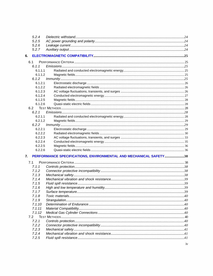
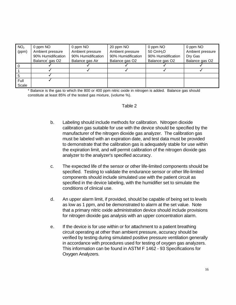

For modular devices test in more than one typical module configuration with the other modules operating
The following should be used to verify proper device alarming capabilities and self test functions in the subsequent sections of the test methods
a Visual status indicators (alarms)
Determine by inspection the presence and proper operation of warning indicators and device status indicators
b Audible status indicators (alarms)
Determine by inspection the presence and proper operation of the audible status indicators Measure and record the frequency temporal characteristics and sound level of the indicators at 1 meter Devices intended for home use should feature continuously sounding warning indicators with sound levels not less than 85 dB(A) and warning indicators of devices intended for hospital use should feature sound levels not less than 70 dB(A)
c Remote alarm
Determine proper operation of the remote alarm by connecting the remote alarm during the testing of the device and verifying proper response Also verify that use of remote alarms does not disable the devices alarms
d Self test
It a self test capability is part of the device design the self test capability should be verified Determine by inspection the presence and proper operation of an indicator self-test capability that exercises all indicators upon turn-on Determine by inspection the presence or absence of a sensing andor functional self-test If a functional self-test is present verify its operation
19
SECTION 5 Electrical Safety
51 Performance Criteria
511 Battery power
a When a line-powered medical device is equipped with a battery power back-up this battery back-up should unless the overcurrent protection mechanism described in paragraph 513 of this section has activated automatically activate when power fails for any other reason The device should operate within its specification within 5 seconds or less after the battery backup power activates
b On medical devices equipped with a battery back-up system the battery when charged fully should be capable of supplying power for normal operation for the time duration specified in the device specifications and consistent with its intended use
c When a battery back-up is provided audible and visual battery depletion warning indicators should be provided that activate when the battery depletes to a level of charge that is approaching the lower limit of power that can operate the device within its specification The operating time between the onset of the battery depletion alarm and the end of normal device operation should be stated in the device specification The alarm should remain activated during this period
d Housings containing batteries from which gases can escape during charging or discharging should be ventilated to minimize the risk of accumulation and ignition Battery compartments should be designed to prevent the risk of accidentally short-circuiting the battery
e If a safety hazard or device malfunction might develop by the incorrect connection or replacement of a battery the device should be fitted with a means of preventing incorrect polarity of connection
512 Electrical power indicators
a Power visual status indicators should be provided to indicate that the device is energized Such indicators should be located conspicuously on the device and should distinguish between battery power and line power sources when both sources are provided
20
b In devices incorporating a means for battery charging the charging mode should be visibly indicated to the operator
513 Overcurrent protection
a Overcurrent protection should be provided for all line-powered devices
b An audible warning status indicator should be activated if the overcurrent protection mechanism is activated and operation of the device cannot occur This status indicator (alarm) should be capable of sounding for the time duration identified in device specifications
c Medical devices should not be fitted with protective mechanisms which cause disconnection of the device from the power line (supply mains) by producing a short-circuit which results in operation of an overcurrent protection mechanism
514 Dielectric withstand
Power source conductors patient contact circuits and transducer circuits should be adequately insulated to assure protection of the patient and device from over voltages Therefore the device should meet the requirements of IEC 601-1 Clause 20
515 AC power grounding and polarity
If the device power connector is not polarized the device should operate within its specification in both polarities of power line connector insertion Devices that operate or recharge batteries from the ac power line should operate within specifications when operating from a grounded or an ungrounded power source (ie with the third-wire ground connected and with it disconnected at the plug end of the power cord)
516 Leakage current
The leakage current testing procedures and protocols test results including leakage current measurements and identification of standards to which the measured leakage current complies should be provided in the 510(k) premarket application Devices should meet the requirements of IEC 601-1
21
517 Auxiliary output
Where an auxiliary output is provided
a The device should operate within its specification during and after application of a short-circuit applied to the auxiliary output for 1 minute
b The leakage current requirements of 516 should not be exceeded upon proper connection of an auxiliary device to the auxiliary output This proper connection should be described in the operators manual
52 Test Methods
For modular devices test in more than one typical module configuration with the other modules operating
521 Battery power
a For ac powered devices with battery back-up with the device powered from the ac line simulate normal operation Remove ac power and determine if battery back-up power activates within 5 seconds With the device operating on battery power test as discussed in Sections 41 and 42 Failure of the device to perform within its specification should constitute failure of this test
b Operate the device from a fully charged battery After operation for 90 percent of the battery power time duration specified in the device specifications test in accordance with Sections 41 and 42 Failure of the device to perform within its specification should constitute failure of this test
c Operate the device from a fully charged battery Record the start time and the time at which battery depletion is indicated Test in accordance with Sections 41 and 42 and verify that battery depletion to the level at which the device fails to operate occurs no less than the minimum time duration defined in the device specifications after indication of battery depletion Failure of the device to perform within its specification should constitute failure of this test
d Determine by inspection that housings containing batteries from which gases can escape during charging or discharging are adequately vented Determine by inspection that battery compartments are designed to prevent accidental
22
short-circuiting of the battery
e For user-replaceable batteries attempt to incorrectly connect insert or replace the battery Determine by inspection that there is clear indication that the device is not functioning Then insert or connect the battery correctly and test the device in accordance with Sections 41 and 42 Failure of the device to perform within its specification should constitute failure of this test
522 Electrical power indicators
a Determine by inspection that visual status indicators indicate when the device is energized and that they distinguish between battery power and line power sources when both sources are provided
b For devices incorporating a means for battery charging place the device in the charging mode and determine by inspection that the charging mode is visibly indicated
523 Overcurrent protection
a For ac line-powered devices determine by inspection the presence of overcurrent protection
b For ac line -powered devices activate the overcurrent protection mechanism Record the time at which the audible warning status indicator activates and the time at which it ceases to sound Failure of the alarm to activate or to sound for at least the time duration identified in the device specifications should constitute failure of this test
c For ac line -powered devices operate from a power distribution strip that incorporates a slow-blow fuse or a circuit breaker appropriately rated for the device under test Activate the device overcurrent protection mechanism Activation of the power distribution strip fuse or circuit breaker should constitute failure of this test
23
524 Dielectric withstand
Test for dielectric withstand in accordance with Clause 20 and Appendix E of IEC 601-1
525 AC power grounding and polarity
For devices that recharge batteries or operate from the ac power line disconnect all connections to ground and test the device in accordance with Sections 41 42 521a and 523 If the ac power connector is not polarized reverse the polarity of the ac connection and repeat the test Failure of the device to perform within its specification should constitute failure of this test
526 Leakage current
Test the device in accordance with IEC 601-1 or in accordance wi th other applicable standards with leakage current specifications
527 Auxiliary output
If the device is provided with an auxiliary output
a This output should be short-circuited (all pins connected together) for at least 1 minute with the device in the standard operating modes During and after application of the short-circuit the device should operate within its specification
b With the auxiliary output connected as specified by the manufacturer test device per 526
24
SECTION 6 Electromagnetic Compatibility
61 Performance Criteria
Devices should meet the electromagnetic compatibility requirements contained in sections 61 and 62 and should also meet these requirements when recharging batteries (if applicable) from or operating from a grounded or an ungrounded ac power source (ie with the third-wire ground connected and with it disconnected at the plug end of the power cord)
611 Emissions
The device should operate within its specification without emitting electromagnetic energy in excess of the levels specified below The required emission limit should be that specified by the referenced document adjusted downward by the rms sum of all errors in the measurement of that quantity
6111 Radiated and conducted electromagnetic energy
The device should comply with the relevant requirements of CISPR 11 when tested according to the specified test methods of this guidance document
6112 Magnetic fields
The device should comply with the relevant requirements of RE101 (Army 7-cm distance) of MIL-STD-461D from 30 Hz to 100 kHz when tested at the 7-cm distance according to RE101 of MIL-STD-462D
612 Immunity
The device should operate within its specification during and after exposure to electromagnetic interference at the levels specified below The required immunity level should be the level stated adjusted upward by the rms sum of all errors in the measurement of that quantity with the exception of the lower steady-state ac voltage limit and the line-voltage sag level which should be adjusted downward by the rms sum of the measurement errors The device should not as a result of the specified test condition indicate an equipment alarm exhibit temporary degradation or loss of function or performance which requires operator intervention or system reset or exhibit loss or corruption of stored data Details of test conditions are specified in section 62 of this guidance document
25
6121 Electrostatic discharge
The device should operate within its specification within 5 seconds of air discharges of 2 4 6 and 8 kV applied to insulating surfaces and contact discharges of 2 4 and 6 kV applied to conductive surfaces both positive and negative to include any point on the device accessible to the operator or patient when tested according to IEC 801-2 as specified in section 62 The device should operate within its specification within 5 seconds of contact discharges applied to horizontal and vertical conducting planes in the vicinity of the device as specified in section 62
6122 Radiated electromagnetic fields
The device should operate within its specification during and after exposure to electromagnetic fields at frequencies between 26 MHz and 1 GHz at field strengths up to 3 Vm (when unmodulated) amplitude modulated 80 percent with a sine wave or 100 percent with a square wave A modulation frequency that is within each significant signal-processing passband of the device should used For devices not having a defined passband a modulation frequency of 05 Hz should be used The modulation frequency should be specified in 510(k) premarket notification
6123 AC voltage fluctuations transients and surges
The following items apply to all devices that recharge batteries from or operate from the ac power line
a Steady-state voltage
The device should operate within its specification without changing a voltage selection switch when powered from line voltages between 95 and 132 volts rms The battery power back-up if featured should automatically activate when the line voltage falls below the minimum level necessary for line-powered device operation which should be no greater than 95 volts rms and line-powered operation should automatically resume when the line voltage returns to the 95-to-132-volt range
b Dropout
The device should operate within its specification during and after line voltage dropouts for durations of 10 milliseconds and less
26
c Slow sags and surges
The device should operate within its specification during and after line voltage surges to 150 V rms and sags to 90 V rms for durations of 500 ms and less
d Fast transient bursts
The device should operate within its specification during and after bursts of transients of 05 1 and 2 kV applied to ac power leads and transients of 025 05 and 1 kV coupled by way of a capacitive clamp to signal leads when tested according to IEC 801-4 with the exception that the burst repetition frequency should not exceed 30 per minute
e Fast surges
The device should operate within its specification during and after exposure to combination voltagecurrent transients applied to AC power leads as specified in section (m) from a test generator as follows
Open-circuit voltage differential mode 1 kV Open-circuit voltage common mode 2 kV Open-circuit voltage risetime 12 microseconds Open-circuit voltage falltime 50 microseconds Generator source impedance 2 ohms Short-circuit current risetime 8 microseconds Short-circuit current falltime 20 microseconds Surge repetition rate 1 per minute
6124 Conducted electromagnetic energy
The device should operate within its specification during and after exposure of each interconnecting cable including power cables to conducted electromagnetic energy at frequencies between 10 kHz and 100 MHz at the levels specified in CS114 Curve 3 of MIL-STD-461D when tested according to CS114 of MIL-STD-462D A modulation frequency that is within each significant signal-processing passband of the device should be used For devices not having a defined passband a modulation frequency of 05 Hz should be used The modulation frequency should be specified in the 510(k) premarket notification
27
6125 Magnetic fields
The device should operate within its specification during and after exposure to magnetic fields at frequencies between 30 Hz and 100 kHz as specified in RS101 (Army) of MILshySTD-461D when tested according to RS101 of MIL-STD-462D A modulation frequency that is within each significant signal-processing passband of the device should be used For devices not having a defined passband a modulation frequency of 05 Hz should be used The modulation frequency should be specified in the 510(k) premarket notification
6126 Quasi-static electric fields
The device should operate within its specification during and after exposure to a sinusoidally varying electric field at 05 Hz with peak field strengths up to 2000 volts per meter Note This test simulates the movement of electrostatically charged fabrics and objects that could come into close proximity to the device
62 Test Methods
Devices should be tested for electromagnetic emissions and immunity to electromagnetic interference as described herein Devices should be tested with the third wire ground connected at the plug end of the power cord Devices intended for home use should be tested with the third wire ground connected and with it disconnected at the plug end of the power cord
621 Emissions
Emissions measurements should be made as specified in the referenced document The required emission limit should be that specified by the referenced document adjusted downward by the rms sum of all errors in the measurement of that quantity Emission in excess of the adjusted limit should constitute failure of this test These tests should be conducted using passive patient simulators which in general are not capable of simulating normal patient signals
6211 Radiated and conducted electromagnetic energy
The device should be tested according to CISPR 11
28
6212 Magnetic fields
The device should be tested for radiated magnetic field emissions between 30 Hz and 100 kHz as specified in RE101 of MIL -STD -462D using the Army 7-cm limit Measurements should be made at the 7-cm distance only
622 Immunity
Immunity of the device to electromagnetic interference should be determined as specified in the referenced document with the modifications listed below The required immunity level should be the level stated adjusted upward by the rms sum of all errors in the measurement of that quantity with the exception of the lower steady-state ac voltage limit and the line-voltage sag level which should be adjusted downward by the rms sum of the measurement errors Any of the following should constitute failure of this test an equipment alarm temporary degradation or loss of function or performance which requires operator intervention or system reset or loss or corruption of stored data Patient simulators should be used to provide simulated normal stimulus to sensors during electromagnetic immunity testing
6221 Electrostatic discharge
The device should be tested with air discharges at 2 4 6 and 8 kV applied to insulating surfaces and contact discharges at 2 4 and 6 kV applied to conductive surfaces Failure to resume normal operation (with no operator intervention) within 5 seconds of a discharge should constitute failure of this test All test failure conditions listed above apply The device should be tested according to IEC 801-2 with the following conditions and modifications
a The device should be tested according to the test method described in IEC 801-2 for table-top equipment
b The relative humidity should not exceed 50 percent during air discharges
c Air discharges should b e conducted at 2 4 6 and 8 kV Contact discharges should be conducted at 2 4 and 6 kV Discharges of both positive and negative polarity should be conducted at each voltage
d In addition to air and contact discharges directly to the device conta ct discharges should be made to the horizontal coupling plane under the device and to the vertical coupling plane positioned parallel to the faces of the device At least 10 single discharges at each test voltage and polarity should be
29
applied to each test point
6222 Radiated electromagnetic fields
a Test conditions
i The device should be tested for immunity to radiated electromagnetic energy over the frequency range 26 MHz to 1 GHz at a field strength of 3 Vm The RF carrier should be amplitude modulated 80 percent by a sine wave or 100 percent with a square wave A modulation frequency that is within each significant signal-processing passband of the device should be used For devices not having a defined passband a modulation frequency of 05 Hz should be used The modulation frequency should be specified in the 510(k) premarket application
ii If a continuous sweep of the test frequency is used the sweep rate should not exceed 01 MHzsecond If the sweep is incremental the step size should not exceed 1 MHz and the dwell time at each frequency should be 10 seconds
iii Devices which can operate from both line and battery power should be tested both with the ac power connection (eg power cord battery charger) attached and detached from the device
iv Patient simulators used during the test should be either simple passive devices isolated from earth ground using fiber optics or battery operated and shielded
v Connections not normally used during device operation that are made to the device to assess performance during the test should be isolated using fiber optics
vi The radiated electric field should be linearly polarized The test should be performed with both horizontal and vertical polarization
vii A planar area of uniform field should be established that contains the front surface of all components of the device under test including cables The boundaries of the area of uniform field should include the maximum planar area occupied in any orientation of the parts of the device The E-field should be measured at multiple points within the area of uniform field with all accessories and physical components of the device
30
removed from the field
Within the area of uniform field the uniformity of the component of the electric field that is aligned with the intended E-field polarization should be -0 +6 dB measured with no amplitude modulation present on the exposure field At a minimum point measurements should be performed at every incremental frequency in the 26 to 1000 MHz frequency range as specified in 6222ii E-field measurements should be made at uniformly spaced points throughout the entire surface of the area of uniform field for both horizontal and vertical polarization The spacing between these points in both the vertical and horizontal directions should be 05 m or less At each point the component of the E-field that is aligned with the intended polarization should not differ from the total E-field at that point by more than 3 dB
For a given facility if placement of absorber antennas and area of uniform field are carefully reproduced it should be necessary to map the area of uniform field only occasionally eg once per year Prior to a series of tests the area of uniform field should be checked along a vertical line near the center with measurements made at uniformly spaced points having a spacing of 05 m or less The E-field measured at these points should meet the uniformity requirements specified above
RF electric field instruments and measurement procedures should meet the requirements of ANSIIEEE C953 - 1991 The instruments should not perturb the E-fields being measured by more than 2 dB and should measure local E-field strength with an error of less than plusmn3 dB over the frequency range of use The field-sensing elements of the instrument should fit within a spherical volume with a diameter of 15 cm The instrument should be capable of measuring the magnitude of each of the three orthogonal components of the electric field In addition the instrument should be capable of determining the total electric field strength (the square root of the sum of the squares of the three E-field vector components) The above measurements should be measured accurately (plusmn1 dB) regardless of the direction of the radiated electric field (ie the field measuring instrument should be isotropic)
viii When practical the test should be repeated with each of the six faces of the device facing the antenna To the extent possible all cables should be horizontal over the majority of their length throughout the test
31
ix One or more of the following exposure methods should be used (1) an open-area test site with the signal and power leads fully extended horizontally (2) an anechoic chamber (3) a parallel-plate line (4) a screen room (5) a semi-anechoic chamber or (6) a TEM cell In order to cover the entire frequency range combinations of several exposure methods may be used over the portions of the range for which they are most appropriate Where the methods yield different results the open-site test should take precedence from 26 to 200 MHz and the anechoic chamber test should take precedence from 200 MHz to 1 GHz
a Test setup
i When practical all device components and cables should be elevated at least 08 m above any conducting ground plane by low dielectric constant (lt25) nonconducting RF-transparent material When this is not possible device components should be mounted on a bulk nonshyconducting support at least 01 m high All device components should be at least 08 m away from any RF-reflecting objects (eg walls of the exposure facility) The distance may need to be increased at certain frequencies to achieve the required field uniformity
ii For exposure methods in which the device cables cannot be extended fully if the length of any conducting cable is 1 m or less it should be arranged horizontally in the planar area of uniform field If the length of any conducting cable is greater than 1 m in length up to the first three meters should be bundled in a serpentine configuration in the planar area of uniform Conductive leads should be configured on a clean dry plastic foam (eg StyrofoamR) sheet with the dimensions and construction Support pegs should be made of dielectric (eg TeflonR) rods (one quarter inch in diameter) Cables in excess of 3 m should be bundled low-inductively and placed on the non-conducting support
iii RFEMI filters should be used at the devices ac power plug
32
6223 AC voltage fluctuations transients and surges
The tests described below should be performed on all devices intended to recharge batteries or operate from the ac power line
a Steady-state voltage
i Raise the line voltage to 132 volts rms and allow the device to stabilize Test device operation according to sections (k) and (l) Repeat for a voltage of 95 volts rms
ii For devices with battery backup simulate normal patient signals while reducing the line voltage to zero Record the voltage at which the device switches to battery power In addition to the failure criteria listed above failure of the device to automatically switch to battery power or switching to battery power before the line voltage reaches 95 volts rms should constitute failure of this test Continue to test device operation while raising the line voltage to 120 volts rms In addition to the failure criteria listed above failure of the device to automatically switch to line power when the line voltage exceeds 95 volts rms should constitute failure of this test
b Dropout
Operate the device at 95 volts rms lower the line voltage to 0 volts for 10 milliseconds and then restore it to 95 volts rms doing so 10 times at a rate not to exceed 30 per minute
c Slow sags and surges
Operate the device at 120 volts rms Raise the line voltage to 150 volts rms for 500 ms Repeat at 10-second intervals for a total of 10 times Again operate the device at 120 volts rms Lower the line voltage to 90 volts rms for 500 ms Repeat at 10-second intervals for a total of 10 times
d Fast transient bursts
Test ac power leads and signal leads according to IEC 801-4 for type test of table-top equipment with the exception that the burst repetition frequency should not exceed 30 per minute Test supply leads at 05 1 and 2 kV and signal leads at 025 05 and 1 kV
33
e Fast surges
i Test generator
(a) The values of elements Rs1 Rs2 Rm Lr and Cc are such that the generator delivers at a single output a combination voltagecurrent wave characterized by a 1250 micros voltage surge when measured across a high-resistance load (more than 100 ohms) and a 820 micros current surge when measured into a short circuit ie the generator has an effective output impedance of 2 ohms
(b) The generator should be capable of producing an open circuit output voltage of up to 2 kV both positive and negative polarity with wave The generator should be capable of delivering short circuit output current of at least 1 kA
The generator should be triggerable so that the phase angle of the discharge can be set at 0 90 180 and 270 degrees with respect to the ac line voltage
ii Test setup
(a) Capacitive coupling should be used to apply the combination wave to the ac power leads of the device under test
(b) A decoupling network should be used to isolate the device under test from the ac power network Residual test pulse voltage on unsurged leads should not exceed 15 percent of the maximum applied test voltage when the device is disconnected Residual test pulse voltage on the inputs of the decoupling network when the device and the power supply network are disconnected should not exceed 10 percent of the applied test voltage or twice the peak value of the power line voltage whichever is greater
(c) Surges should be applied at the point where the device would normally be connected to ac line power
(d) For the line-to-line test an 18-uF coupling capacitor should be used
(e) For the line-to-ground tests a 10-ohm resistor should be used in
34
series with the test generator and a 9-uF coupling capacitor should be used
iii Test procedure
(a) The line-to-line test should be performed using 1-kV surges of both positive and negative polarity applied using a generator source impedance of 2 ohms and coupling capacitance of 18 uF with the generator output floating
(b) The line-to-ground test should be performed using 2-kV surges of both positive and negative polarity applied using a generator source impedance of 12 ohms and coupling capacitance of 9 uF with the generator output grounded The test should be repeated with surges applied successively between each line and ground
(c) Surges at each amplitude and polarity should be applied at phase angles of 0 90 180 and 270 degrees with respect to the ac line
(d) Each test should be repeated 10 times at a rate of 1 surge per minute
6224 Conducted electromagnetic energy
The device should be tested for immunity to conducted electromagnetic energy on each power and signal lead at frequencies between 10 kHz and 100 MHZ at the levels specified in curve 3 of CS114 of MIL-STD-461D using the test methods specified in CS114 of MIL-STD-462D with the modifications and additions listed below
a If continuous sweep of the test frequency is used the sweep rate should not exceed 1 x 10⁻³ decadessecond If the sweep is incremental the step size should not exceed 1 percent of decade and the minimum dwell time is 10 seconds per step
b A modulation frequency that is within each significant signal-processing passband of the device should be used For devices not having a defined passband a modulation frequency of 05 Hz should be used
c The leads under test should be elevated 5 cm above the ground plane
d For power cables the interference signal should be injected at a distance of 5
35
cm from the point at which ac line power enters the device For battery chargers which plug directly into ac outlets a 10 cm length of wire should be added between the LISN and the charger and the test signal should be injected 5 cm from the charger The low-voltage output cable of the charger should be elevated 5 cm above the ground plane
6225 Magnetic fields
Test according to RS101 of MIL-STD-462D The test should be performed from 30 Hz to 100 kHz
6226 Quasi-static electric fields
a Test setup
i The device should be tested between parallel horizontal planes They should be metallic sheets (copper or aluminum) of 025 mm minimum thickness which extend at least 01 m beyond the device The horizontal planes should be separated by insulating material with a separation at least three times the height of the device in the position of normal use
ii The device should be supported by insulating material so that it is positioned entirely between 13 and 23 the distance between the horizontal planes
iii Cables and tubing should be supported by insulating material at a height above the bottom horizontal plane of 13 the distance between the planes and should exit the test apparatus and continue at this height for at least 01 meter beyond the horizontal planes
iv The output of a signal generator capable of producing a sinusoidally varying voltage at a frequency of 05 Hz with amplitude sufficient to produce peak electric field strengths up to 2000 Vm between the horizontal planes should be connected to the horizontal planes
Note Ep = VpD where Ep is the peak field strength in Vm Vp is the peak of the signal generator output voltage waveform and D is the distance between the horizontal planes in meters
36
b Test procedure
Adjust the signal generator peak output voltage such that the device is exposed to a sinusoidally varying electric field at 05 Hz with peak field strength of 500 Vm Gradually increase the peak field strength to 2000 Vm
37
SECTION 7 Performance Specifications Environmental and Mechanical Safety
71 Performance Criteria
711 Controls protection
The controls of medical devices should be protected from inadvertent or unauthorized changes or adjustment The means of protection should be such as to preclude their defeat by patients or other unauthorized persons
All controls which increase or decrease a function should be marked with a legible indication to inform the operator which action(s) is (are) required to increasedecrease the controlled function Controls and their associated markings should be visible or legible or both to an operator having a visual acuity of at least 10 when the operator is located at lest 1 meter in front of the device and the ambient illuminance level is 215 lx when viewing the information marking etc perpendicular to and including 15 degrees above below left and right Controls should be identified with their associated markings
For controls movement upwards to right or in a clockwise direction should increase the control function Movement downwards to the left or a counterclockwise direction should decrease the control function Rotary gas flow controls are exempt from this performance criterion
712 Connector protective incompatibility
a Device connectors including those on wires and tubing should be designed such that insertion into a receptacle other than the one into which they are intended to be inserted or into a receptacle using an improper orientation should not be possible
b Electrical connectors of a device (eg electrical lead wires) should include a mechanism to prevent connection of the patient to a power source that may cause a current flow in excess of that specified in paragraph (h)(6)
713 Mechanical safety
Each device should
a Not have any exposed sharp edges
b Be mechanically stable in the intended position(s) of use
38
c Provide protection to the operator and patient from moving parts
714 Mechanical vibration and shock resistance
The device (ie the complete system suitable for its intended use) should withstand the mechanical shocks and vibrations expected in the environments of intended use as defined by the test methods contained herein and should remain operational within its specification
715 Fluid spill resistance
The device should be so constructed that it continues to operate within its specification after fluids have been dripped on the device Therefore the device should meet the requirements for drip-proof equipment as specified in Clause 446 of IEC 601-1 and IEC 529
716 High and low temperature and humidity
a The device should operate within its specification when operating in the environmental temperature range of 5degC to 40degC and in the environmental humidity range of 15 percent to 95 percent noncondensing
b The device should not be damaged and should remain operational within its specification after storage in the environmental temperature range of -20C to 60degC and at relative humidity up to 95 percent non-condensing
717 Surface temperature
Temperature of surfaces of a device an operator can contact during operation should not exceed 50 degrees C in an ambient of 35 degrees C The temperature of surfaces that may come in contact with the patient should not exceed 41 degrees C in an ambient of 35 degrees C Any surface temperature that may come in contact with the patient exceeding 41 degrees C should be justified with a scientifically valid explanation and data should be provided which demonstrates that the safety of the patient is not compromised
39
718 Toxic materials
No toxic material from a device should come in contact with patient or operator during normal use
719 Strangulation
Provision should be made in routing retention devices or other means to minimize the risk of strangulation of the patient by wires or tubing This may also be accomplished by providing instructions for routing of patient wires and tubing in the device labeling
7110 Determination of Endurance
Compliance with device specifications should be determined with one or more samples of production system or components of the system (Nitric Oxide analyzer or Nitrogen Oxide analyzer) Each system or component should be tested for endurance as described in 7211 The system should run for 2000 h
7111 Material Compatibility
Parts should be made of materials that are compatible with the gases and agents with which those components are designed to come into contact and minimize health risks due to substances leached from the device in use
7112 Medical Gas Cylinder Connections
Connectors of calibration gas cylinders not already specified in relevant national standards such as CGA C-9-1982 should be designed differently from the connectors specified for other medical gases
72 Test Methods
721 Controls protection
Test by inspection
722 Connector protective incompatibility
Test by inspection and by attempting the prohibited connections
40
723 Mechanical safety
Test by inspection
724 Mechanical vibration and shock resistance
Test the device (ie the complete system suitable for its intended use) to the following severity levels as specified in the following IEC 68-2 Basic Environmental Testing Procedures Following each of these tests the device should be visually inspected Any evidence of damage or inability to perform within specification should constitute failure of the test
a IEC 68-2-27 SHOCK Peak acceleration 100 g (980 ms2) Duration 6 msec Pulse shape half sine
b IEC 68-2-6 SINUSOIDAL VIBRATION Frequency range 10 to 500 Hz Acceleration amplitude 1 g (98 ms2) Type and duration of endurance 10 sweep cycles in each axis
c IEC 68-2-34 RANDOM VIBRATION WIDE BAND Frequency range 20 Hz - 500 Hz Acceleration spectral density 002 g2Hz Degree of reproducibility low Duration of conditioning 9 minutes
725 Fluid spill resistance
Test the device as specified in Clause 446 of IEC 601-1 for drip-proof and equipment Following each of these tests the device should be visually inspected Any evidence of damage or inability to perform within specification should constitute failure of the test
726 High and low temperature and humidity
Test the device as specified in Method Numbers 5013 5023 and 5073 of MIL-STDshy810E according to the requirements of section (i)(6) of this document Failure of the device to perform within its specification should constitute failure of these tests
41
727 Surface temperature
Operate the device in an ambient temperature of 35degC Measure the temperature of the device surfaces which are not intended to contact the patient The presence of any temperature greater than 50degC should constitute failure of this test Measure the temperature of device surfaces which are likely to contact the patient in normal use Any temperature above 41degC should constitute failure of this test
728 Toxic materials
Determine by inspection that listed and any other known toxic materials used in the device are packaged in a manner that prevents patient and operator contact
729 Strangulation
Test by inspection
7210 Determination of Endurance
Simulated testing should be performed using a ventilator test lung humidifier delivery apparatus and analyzers The inspriatoryexpiratory phase time ratio should be as close to 12 as possible and run the test system for 2000 hours with appropriate patient population settings The delivery apparatus should titrate at least 20 ppm of Nitric Oxide throughout the duration of the testing
7211 Material Compatibility
Parts which come in contact with the gases and agents should be revalidated to ensure that the specifications are met after the endurance testing Simulated testing should address issues such as corrosion and chemical interaction which could affect mechanical or electrical properties
42
SECTION 8 Hardware Documentation
This information should include a description of the hardware requirements device performance requirements the potential system hazards and the hardware andor software functions implemented as a result of such potential hazards Documentation of the hardware development process including quality assurance activities configuration management plan and verification activities and summaries in accordance with the appropriate level of concern should also be provided The hardware information should include the most recent verification and validation test plansprotocols identification of which activities were performed prior to and after hardwaresoftware integration verification and validation results and analyses showing that specifications were met at each appropriate level of hardware Written affirmation stating that the described hardware was developed and tested according to the stated proceduresmethods and test showed requirements were met should be provided The hardware information should also identify of the version level featured in the final design of the device
43
SECTION 9 Software Documentation
If the device is software-driven the premarket notification should include software information in accordance with the Guidance for the content of Premarket Submissions for Software Contained in Medical Devices This information should include a description of the software requirements device performance requirements the potential system hazards and the software andor hardware functions implemented as a result of such potential hazards Documentation of the software development process including quality assurance activities configuration management plan and verification activities and summaries in accordance with the appropriate level of concern as discussed in the current guidance for software should also be provided The level of concern should be identified with the hazard analysis The software information should include the most recent verification and validation test plansprotocols identification of which activities were performed prior to and after softwarehardware integration verification and validation results and analyses showing that specifications were met at each appropriate level of software Written affirmation stating that the described software was developed and tested according to the stated proceduresmethods and test showed requirements were met should be provided The software information should also identify of the software version level featured in the final design of the device
44
SECTION 10 Labeling
The premarket notification should include all labeling (ie device labels instructions for use promotional material) for the device under review Recommendations for labeling content are included in the Device Labeling Guidance (ODE Blue Book G91-1) and specific labeling discussed in this guidance
The nitric oxide administration apparatus nitric oxide gas analyzer and nitrogen dioxide gas analyzer are restricted to use only upon the written or oral authorization of a practitioner licensed by law to use the device and that the device be restricted to use by persons with experience or training in its use In accordance with 21 CFR 801109(b)(1) the labeling for prescription devices is required to bear the required caution prescription statement This statement should read Caution Federal law restricts this device to sale by or on the order of a physician or other licensed medical practitioner
The nitric oxide administration apparatus nitric oxide gas analyzer and nitrogen dioxide gas analyzer labeling should include a warning that ldquoPersons using this device should be trained and experienced in the use of this device to assure effective administration of nitric oxide and to avoid injury to the patient or to others resulting from inhalation of excess nitric oxide nitrogen dioxide or other reaction productsrdquo
101 Identification of Medical Gas Cylinders and Connections
Colors of calibration gas cylinders not already specified in relevant national standards such as CGA C-9-1982 should be color-coded differently from the colors specified for medical gases
102 Instructions for Use
1021 Intended Use
The instructions for use should include a description of the intended use and a description of the principles of operation of the components of the Nitric Oxide System
1022 Validated Ventilators
The instructions for use should include a list of ventilators that have been validated for use with the nitric oxide administration device nitric oxide analyzer and nitrogen dioxide analyzer
45
1023 Installation Instructions
The instructions for use should include a description of the correct installation of the Nitric Oxide System or any of its components
46
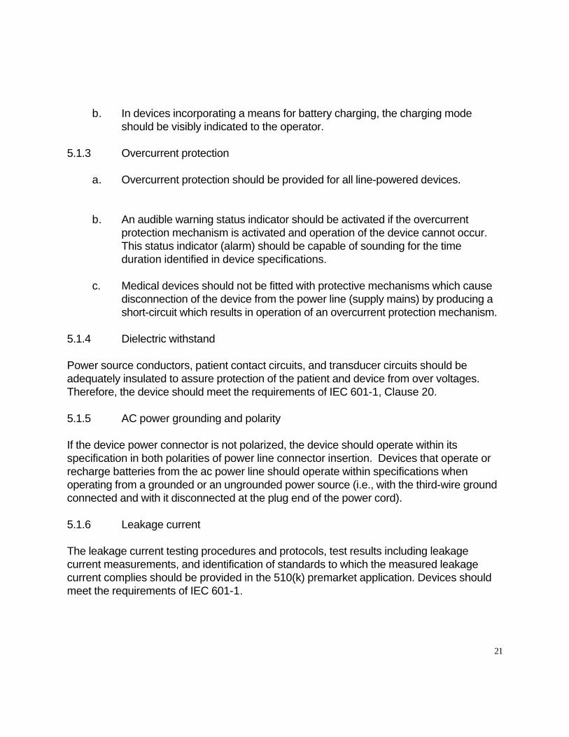

c Slow sags and surges
The device should operate within its specification during and after line voltage surges to 150 V rms and sags to 90 V rms for durations of 500 ms and less
d Fast transient bursts
The device should operate within its specification during and after bursts of transients of 05 1 and 2 kV applied to ac power leads and transients of 025 05 and 1 kV coupled by way of a capacitive clamp to signal leads when tested according to IEC 801-4 with the exception that the burst repetition frequency should not exceed 30 per minute
e Fast surges
The device should operate within its specification during and after exposure to combination voltagecurrent transients applied to AC power leads as specified in section (m) from a test generator as follows
Open-circuit voltage differential mode 1 kV Open-circuit voltage common mode 2 kV Open-circuit voltage risetime 12 microseconds Open-circuit voltage falltime 50 microseconds Generator source impedance 2 ohms Short-circuit current risetime 8 microseconds Short-circuit current falltime 20 microseconds Surge repetition rate 1 per minute
6124 Conducted electromagnetic energy
The device should operate within its specification during and after exposure of each interconnecting cable including power cables to conducted electromagnetic energy at frequencies between 10 kHz and 100 MHz at the levels specified in CS114 Curve 3 of MIL-STD-461D when tested according to CS114 of MIL-STD-462D A modulation frequency that is within each significant signal-processing passband of the device should be used For devices not having a defined passband a modulation frequency of 05 Hz should be used The modulation frequency should be specified in the 510(k) premarket notification
27
6125 Magnetic fields
The device should operate within its specification during and after exposure to magnetic fields at frequencies between 30 Hz and 100 kHz as specified in RS101 (Army) of MILshySTD-461D when tested according to RS101 of MIL-STD-462D A modulation frequency that is within each significant signal-processing passband of the device should be used For devices not having a defined passband a modulation frequency of 05 Hz should be used The modulation frequency should be specified in the 510(k) premarket notification
6126 Quasi-static electric fields
The device should operate within its specification during and after exposure to a sinusoidally varying electric field at 05 Hz with peak field strengths up to 2000 volts per meter Note This test simulates the movement of electrostatically charged fabrics and objects that could come into close proximity to the device
62 Test Methods
Devices should be tested for electromagnetic emissions and immunity to electromagnetic interference as described herein Devices should be tested with the third wire ground connected at the plug end of the power cord Devices intended for home use should be tested with the third wire ground connected and with it disconnected at the plug end of the power cord
621 Emissions
Emissions measurements should be made as specified in the referenced document The required emission limit should be that specified by the referenced document adjusted downward by the rms sum of all errors in the measurement of that quantity Emission in excess of the adjusted limit should constitute failure of this test These tests should be conducted using passive patient simulators which in general are not capable of simulating normal patient signals
6211 Radiated and conducted electromagnetic energy
The device should be tested according to CISPR 11
28
6212 Magnetic fields
The device should be tested for radiated magnetic field emissions between 30 Hz and 100 kHz as specified in RE101 of MIL -STD -462D using the Army 7-cm limit Measurements should be made at the 7-cm distance only
622 Immunity
Immunity of the device to electromagnetic interference should be determined as specified in the referenced document with the modifications listed below The required immunity level should be the level stated adjusted upward by the rms sum of all errors in the measurement of that quantity with the exception of the lower steady-state ac voltage limit and the line-voltage sag level which should be adjusted downward by the rms sum of the measurement errors Any of the following should constitute failure of this test an equipment alarm temporary degradation or loss of function or performance which requires operator intervention or system reset or loss or corruption of stored data Patient simulators should be used to provide simulated normal stimulus to sensors during electromagnetic immunity testing
6221 Electrostatic discharge
The device should be tested with air discharges at 2 4 6 and 8 kV applied to insulating surfaces and contact discharges at 2 4 and 6 kV applied to conductive surfaces Failure to resume normal operation (with no operator intervention) within 5 seconds of a discharge should constitute failure of this test All test failure conditions listed above apply The device should be tested according to IEC 801-2 with the following conditions and modifications
a The device should be tested according to the test method described in IEC 801-2 for table-top equipment
b The relative humidity should not exceed 50 percent during air discharges
c Air discharges should b e conducted at 2 4 6 and 8 kV Contact discharges should be conducted at 2 4 and 6 kV Discharges of both positive and negative polarity should be conducted at each voltage
d In addition to air and contact discharges directly to the device conta ct discharges should be made to the horizontal coupling plane under the device and to the vertical coupling plane positioned parallel to the faces of the device At least 10 single discharges at each test voltage and polarity should be
29
applied to each test point
6222 Radiated electromagnetic fields
a Test conditions
i The device should be tested for immunity to radiated electromagnetic energy over the frequency range 26 MHz to 1 GHz at a field strength of 3 Vm The RF carrier should be amplitude modulated 80 percent by a sine wave or 100 percent with a square wave A modulation frequency that is within each significant signal-processing passband of the device should be used For devices not having a defined passband a modulation frequency of 05 Hz should be used The modulation frequency should be specified in the 510(k) premarket application
ii If a continuous sweep of the test frequency is used the sweep rate should not exceed 01 MHzsecond If the sweep is incremental the step size should not exceed 1 MHz and the dwell time at each frequency should be 10 seconds
iii Devices which can operate from both line and battery power should be tested both with the ac power connection (eg power cord battery charger) attached and detached from the device
iv Patient simulators used during the test should be either simple passive devices isolated from earth ground using fiber optics or battery operated and shielded
v Connections not normally used during device operation that are made to the device to assess performance during the test should be isolated using fiber optics
vi The radiated electric field should be linearly polarized The test should be performed with both horizontal and vertical polarization
vii A planar area of uniform field should be established that contains the front surface of all components of the device under test including cables The boundaries of the area of uniform field should include the maximum planar area occupied in any orientation of the parts of the device The E-field should be measured at multiple points within the area of uniform field with all accessories and physical components of the device
30
removed from the field
Within the area of uniform field the uniformity of the component of the electric field that is aligned with the intended E-field polarization should be -0 +6 dB measured with no amplitude modulation present on the exposure field At a minimum point measurements should be performed at every incremental frequency in the 26 to 1000 MHz frequency range as specified in 6222ii E-field measurements should be made at uniformly spaced points throughout the entire surface of the area of uniform field for both horizontal and vertical polarization The spacing between these points in both the vertical and horizontal directions should be 05 m or less At each point the component of the E-field that is aligned with the intended polarization should not differ from the total E-field at that point by more than 3 dB
For a given facility if placement of absorber antennas and area of uniform field are carefully reproduced it should be necessary to map the area of uniform field only occasionally eg once per year Prior to a series of tests the area of uniform field should be checked along a vertical line near the center with measurements made at uniformly spaced points having a spacing of 05 m or less The E-field measured at these points should meet the uniformity requirements specified above
RF electric field instruments and measurement procedures should meet the requirements of ANSIIEEE C953 - 1991 The instruments should not perturb the E-fields being measured by more than 2 dB and should measure local E-field strength with an error of less than plusmn3 dB over the frequency range of use The field-sensing elements of the instrument should fit within a spherical volume with a diameter of 15 cm The instrument should be capable of measuring the magnitude of each of the three orthogonal components of the electric field In addition the instrument should be capable of determining the total electric field strength (the square root of the sum of the squares of the three E-field vector components) The above measurements should be measured accurately (plusmn1 dB) regardless of the direction of the radiated electric field (ie the field measuring instrument should be isotropic)
viii When practical the test should be repeated with each of the six faces of the device facing the antenna To the extent possible all cables should be horizontal over the majority of their length throughout the test
31
ix One or more of the following exposure methods should be used (1) an open-area test site with the signal and power leads fully extended horizontally (2) an anechoic chamber (3) a parallel-plate line (4) a screen room (5) a semi-anechoic chamber or (6) a TEM cell In order to cover the entire frequency range combinations of several exposure methods may be used over the portions of the range for which they are most appropriate Where the methods yield different results the open-site test should take precedence from 26 to 200 MHz and the anechoic chamber test should take precedence from 200 MHz to 1 GHz
a Test setup
i When practical all device components and cables should be elevated at least 08 m above any conducting ground plane by low dielectric constant (lt25) nonconducting RF-transparent material When this is not possible device components should be mounted on a bulk nonshyconducting support at least 01 m high All device components should be at least 08 m away from any RF-reflecting objects (eg walls of the exposure facility) The distance may need to be increased at certain frequencies to achieve the required field uniformity
ii For exposure methods in which the device cables cannot be extended fully if the length of any conducting cable is 1 m or less it should be arranged horizontally in the planar area of uniform field If the length of any conducting cable is greater than 1 m in length up to the first three meters should be bundled in a serpentine configuration in the planar area of uniform Conductive leads should be configured on a clean dry plastic foam (eg StyrofoamR) sheet with the dimensions and construction Support pegs should be made of dielectric (eg TeflonR) rods (one quarter inch in diameter) Cables in excess of 3 m should be bundled low-inductively and placed on the non-conducting support
iii RFEMI filters should be used at the devices ac power plug
32
6223 AC voltage fluctuations transients and surges
The tests described below should be performed on all devices intended to recharge batteries or operate from the ac power line
a Steady-state voltage
i Raise the line voltage to 132 volts rms and allow the device to stabilize Test device operation according to sections (k) and (l) Repeat for a voltage of 95 volts rms
ii For devices with battery backup simulate normal patient signals while reducing the line voltage to zero Record the voltage at which the device switches to battery power In addition to the failure criteria listed above failure of the device to automatically switch to battery power or switching to battery power before the line voltage reaches 95 volts rms should constitute failure of this test Continue to test device operation while raising the line voltage to 120 volts rms In addition to the failure criteria listed above failure of the device to automatically switch to line power when the line voltage exceeds 95 volts rms should constitute failure of this test
b Dropout
Operate the device at 95 volts rms lower the line voltage to 0 volts for 10 milliseconds and then restore it to 95 volts rms doing so 10 times at a rate not to exceed 30 per minute
c Slow sags and surges
Operate the device at 120 volts rms Raise the line voltage to 150 volts rms for 500 ms Repeat at 10-second intervals for a total of 10 times Again operate the device at 120 volts rms Lower the line voltage to 90 volts rms for 500 ms Repeat at 10-second intervals for a total of 10 times
d Fast transient bursts
Test ac power leads and signal leads according to IEC 801-4 for type test of table-top equipment with the exception that the burst repetition frequency should not exceed 30 per minute Test supply leads at 05 1 and 2 kV and signal leads at 025 05 and 1 kV
33
e Fast surges
i Test generator
(a) The values of elements Rs1 Rs2 Rm Lr and Cc are such that the generator delivers at a single output a combination voltagecurrent wave characterized by a 1250 micros voltage surge when measured across a high-resistance load (more than 100 ohms) and a 820 micros current surge when measured into a short circuit ie the generator has an effective output impedance of 2 ohms
(b) The generator should be capable of producing an open circuit output voltage of up to 2 kV both positive and negative polarity with wave The generator should be capable of delivering short circuit output current of at least 1 kA
The generator should be triggerable so that the phase angle of the discharge can be set at 0 90 180 and 270 degrees with respect to the ac line voltage
ii Test setup
(a) Capacitive coupling should be used to apply the combination wave to the ac power leads of the device under test
(b) A decoupling network should be used to isolate the device under test from the ac power network Residual test pulse voltage on unsurged leads should not exceed 15 percent of the maximum applied test voltage when the device is disconnected Residual test pulse voltage on the inputs of the decoupling network when the device and the power supply network are disconnected should not exceed 10 percent of the applied test voltage or twice the peak value of the power line voltage whichever is greater
(c) Surges should be applied at the point where the device would normally be connected to ac line power
(d) For the line-to-line test an 18-uF coupling capacitor should be used
(e) For the line-to-ground tests a 10-ohm resistor should be used in
34
series with the test generator and a 9-uF coupling capacitor should be used
iii Test procedure
(a) The line-to-line test should be performed using 1-kV surges of both positive and negative polarity applied using a generator source impedance of 2 ohms and coupling capacitance of 18 uF with the generator output floating
(b) The line-to-ground test should be performed using 2-kV surges of both positive and negative polarity applied using a generator source impedance of 12 ohms and coupling capacitance of 9 uF with the generator output grounded The test should be repeated with surges applied successively between each line and ground
(c) Surges at each amplitude and polarity should be applied at phase angles of 0 90 180 and 270 degrees with respect to the ac line
(d) Each test should be repeated 10 times at a rate of 1 surge per minute
6224 Conducted electromagnetic energy
The device should be tested for immunity to conducted electromagnetic energy on each power and signal lead at frequencies between 10 kHz and 100 MHZ at the levels specified in curve 3 of CS114 of MIL-STD-461D using the test methods specified in CS114 of MIL-STD-462D with the modifications and additions listed below
a If continuous sweep of the test frequency is used the sweep rate should not exceed 1 x 10⁻³ decadessecond If the sweep is incremental the step size should not exceed 1 percent of decade and the minimum dwell time is 10 seconds per step
b A modulation frequency that is within each significant signal-processing passband of the device should be used For devices not having a defined passband a modulation frequency of 05 Hz should be used
c The leads under test should be elevated 5 cm above the ground plane
d For power cables the interference signal should be injected at a distance of 5
35
cm from the point at which ac line power enters the device For battery chargers which plug directly into ac outlets a 10 cm length of wire should be added between the LISN and the charger and the test signal should be injected 5 cm from the charger The low-voltage output cable of the charger should be elevated 5 cm above the ground plane
6225 Magnetic fields
Test according to RS101 of MIL-STD-462D The test should be performed from 30 Hz to 100 kHz
6226 Quasi-static electric fields
a Test setup
i The device should be tested between parallel horizontal planes They should be metallic sheets (copper or aluminum) of 025 mm minimum thickness which extend at least 01 m beyond the device The horizontal planes should be separated by insulating material with a separation at least three times the height of the device in the position of normal use
ii The device should be supported by insulating material so that it is positioned entirely between 13 and 23 the distance between the horizontal planes
iii Cables and tubing should be supported by insulating material at a height above the bottom horizontal plane of 13 the distance between the planes and should exit the test apparatus and continue at this height for at least 01 meter beyond the horizontal planes
iv The output of a signal generator capable of producing a sinusoidally varying voltage at a frequency of 05 Hz with amplitude sufficient to produce peak electric field strengths up to 2000 Vm between the horizontal planes should be connected to the horizontal planes
Note Ep = VpD where Ep is the peak field strength in Vm Vp is the peak of the signal generator output voltage waveform and D is the distance between the horizontal planes in meters
36
b Test procedure
Adjust the signal generator peak output voltage such that the device is exposed to a sinusoidally varying electric field at 05 Hz with peak field strength of 500 Vm Gradually increase the peak field strength to 2000 Vm
37
SECTION 7 Performance Specifications Environmental and Mechanical Safety
71 Performance Criteria
711 Controls protection
The controls of medical devices should be protected from inadvertent or unauthorized changes or adjustment The means of protection should be such as to preclude their defeat by patients or other unauthorized persons
All controls which increase or decrease a function should be marked with a legible indication to inform the operator which action(s) is (are) required to increasedecrease the controlled function Controls and their associated markings should be visible or legible or both to an operator having a visual acuity of at least 10 when the operator is located at lest 1 meter in front of the device and the ambient illuminance level is 215 lx when viewing the information marking etc perpendicular to and including 15 degrees above below left and right Controls should be identified with their associated markings
For controls movement upwards to right or in a clockwise direction should increase the control function Movement downwards to the left or a counterclockwise direction should decrease the control function Rotary gas flow controls are exempt from this performance criterion
712 Connector protective incompatibility
a Device connectors including those on wires and tubing should be designed such that insertion into a receptacle other than the one into which they are intended to be inserted or into a receptacle using an improper orientation should not be possible
b Electrical connectors of a device (eg electrical lead wires) should include a mechanism to prevent connection of the patient to a power source that may cause a current flow in excess of that specified in paragraph (h)(6)
713 Mechanical safety
Each device should
a Not have any exposed sharp edges
b Be mechanically stable in the intended position(s) of use
38
c Provide protection to the operator and patient from moving parts
714 Mechanical vibration and shock resistance
The device (ie the complete system suitable for its intended use) should withstand the mechanical shocks and vibrations expected in the environments of intended use as defined by the test methods contained herein and should remain operational within its specification
715 Fluid spill resistance
The device should be so constructed that it continues to operate within its specification after fluids have been dripped on the device Therefore the device should meet the requirements for drip-proof equipment as specified in Clause 446 of IEC 601-1 and IEC 529
716 High and low temperature and humidity
a The device should operate within its specification when operating in the environmental temperature range of 5degC to 40degC and in the environmental humidity range of 15 percent to 95 percent noncondensing
b The device should not be damaged and should remain operational within its specification after storage in the environmental temperature range of -20C to 60degC and at relative humidity up to 95 percent non-condensing
717 Surface temperature
Temperature of surfaces of a device an operator can contact during operation should not exceed 50 degrees C in an ambient of 35 degrees C The temperature of surfaces that may come in contact with the patient should not exceed 41 degrees C in an ambient of 35 degrees C Any surface temperature that may come in contact with the patient exceeding 41 degrees C should be justified with a scientifically valid explanation and data should be provided which demonstrates that the safety of the patient is not compromised
39
718 Toxic materials
No toxic material from a device should come in contact with patient or operator during normal use
719 Strangulation
Provision should be made in routing retention devices or other means to minimize the risk of strangulation of the patient by wires or tubing This may also be accomplished by providing instructions for routing of patient wires and tubing in the device labeling
7110 Determination of Endurance
Compliance with device specifications should be determined with one or more samples of production system or components of the system (Nitric Oxide analyzer or Nitrogen Oxide analyzer) Each system or component should be tested for endurance as described in 7211 The system should run for 2000 h
7111 Material Compatibility
Parts should be made of materials that are compatible with the gases and agents with which those components are designed to come into contact and minimize health risks due to substances leached from the device in use
7112 Medical Gas Cylinder Connections
Connectors of calibration gas cylinders not already specified in relevant national standards such as CGA C-9-1982 should be designed differently from the connectors specified for other medical gases
72 Test Methods
721 Controls protection
Test by inspection
722 Connector protective incompatibility
Test by inspection and by attempting the prohibited connections
40
723 Mechanical safety
Test by inspection
724 Mechanical vibration and shock resistance
Test the device (ie the complete system suitable for its intended use) to the following severity levels as specified in the following IEC 68-2 Basic Environmental Testing Procedures Following each of these tests the device should be visually inspected Any evidence of damage or inability to perform within specification should constitute failure of the test
a IEC 68-2-27 SHOCK Peak acceleration 100 g (980 ms2) Duration 6 msec Pulse shape half sine
b IEC 68-2-6 SINUSOIDAL VIBRATION Frequency range 10 to 500 Hz Acceleration amplitude 1 g (98 ms2) Type and duration of endurance 10 sweep cycles in each axis
c IEC 68-2-34 RANDOM VIBRATION WIDE BAND Frequency range 20 Hz - 500 Hz Acceleration spectral density 002 g2Hz Degree of reproducibility low Duration of conditioning 9 minutes
725 Fluid spill resistance
Test the device as specified in Clause 446 of IEC 601-1 for drip-proof and equipment Following each of these tests the device should be visually inspected Any evidence of damage or inability to perform within specification should constitute failure of the test
726 High and low temperature and humidity
Test the device as specified in Method Numbers 5013 5023 and 5073 of MIL-STDshy810E according to the requirements of section (i)(6) of this document Failure of the device to perform within its specification should constitute failure of these tests
41
727 Surface temperature
Operate the device in an ambient temperature of 35degC Measure the temperature of the device surfaces which are not intended to contact the patient The presence of any temperature greater than 50degC should constitute failure of this test Measure the temperature of device surfaces which are likely to contact the patient in normal use Any temperature above 41degC should constitute failure of this test
728 Toxic materials
Determine by inspection that listed and any other known toxic materials used in the device are packaged in a manner that prevents patient and operator contact
729 Strangulation
Test by inspection
7210 Determination of Endurance
Simulated testing should be performed using a ventilator test lung humidifier delivery apparatus and analyzers The inspriatoryexpiratory phase time ratio should be as close to 12 as possible and run the test system for 2000 hours with appropriate patient population settings The delivery apparatus should titrate at least 20 ppm of Nitric Oxide throughout the duration of the testing
7211 Material Compatibility
Parts which come in contact with the gases and agents should be revalidated to ensure that the specifications are met after the endurance testing Simulated testing should address issues such as corrosion and chemical interaction which could affect mechanical or electrical properties
42
SECTION 8 Hardware Documentation
This information should include a description of the hardware requirements device performance requirements the potential system hazards and the hardware andor software functions implemented as a result of such potential hazards Documentation of the hardware development process including quality assurance activities configuration management plan and verification activities and summaries in accordance with the appropriate level of concern should also be provided The hardware information should include the most recent verification and validation test plansprotocols identification of which activities were performed prior to and after hardwaresoftware integration verification and validation results and analyses showing that specifications were met at each appropriate level of hardware Written affirmation stating that the described hardware was developed and tested according to the stated proceduresmethods and test showed requirements were met should be provided The hardware information should also identify of the version level featured in the final design of the device
43
SECTION 9 Software Documentation
If the device is software-driven the premarket notification should include software information in accordance with the Guidance for the content of Premarket Submissions for Software Contained in Medical Devices This information should include a description of the software requirements device performance requirements the potential system hazards and the software andor hardware functions implemented as a result of such potential hazards Documentation of the software development process including quality assurance activities configuration management plan and verification activities and summaries in accordance with the appropriate level of concern as discussed in the current guidance for software should also be provided The level of concern should be identified with the hazard analysis The software information should include the most recent verification and validation test plansprotocols identification of which activities were performed prior to and after softwarehardware integration verification and validation results and analyses showing that specifications were met at each appropriate level of software Written affirmation stating that the described software was developed and tested according to the stated proceduresmethods and test showed requirements were met should be provided The software information should also identify of the software version level featured in the final design of the device
44
SECTION 10 Labeling
The premarket notification should include all labeling (ie device labels instructions for use promotional material) for the device under review Recommendations for labeling content are included in the Device Labeling Guidance (ODE Blue Book G91-1) and specific labeling discussed in this guidance
The nitric oxide administration apparatus nitric oxide gas analyzer and nitrogen dioxide gas analyzer are restricted to use only upon the written or oral authorization of a practitioner licensed by law to use the device and that the device be restricted to use by persons with experience or training in its use In accordance with 21 CFR 801109(b)(1) the labeling for prescription devices is required to bear the required caution prescription statement This statement should read Caution Federal law restricts this device to sale by or on the order of a physician or other licensed medical practitioner
The nitric oxide administration apparatus nitric oxide gas analyzer and nitrogen dioxide gas analyzer labeling should include a warning that ldquoPersons using this device should be trained and experienced in the use of this device to assure effective administration of nitric oxide and to avoid injury to the patient or to others resulting from inhalation of excess nitric oxide nitrogen dioxide or other reaction productsrdquo
101 Identification of Medical Gas Cylinders and Connections
Colors of calibration gas cylinders not already specified in relevant national standards such as CGA C-9-1982 should be color-coded differently from the colors specified for medical gases
102 Instructions for Use
1021 Intended Use
The instructions for use should include a description of the intended use and a description of the principles of operation of the components of the Nitric Oxide System
1022 Validated Ventilators
The instructions for use should include a list of ventilators that have been validated for use with the nitric oxide administration device nitric oxide analyzer and nitrogen dioxide analyzer
45
1023 Installation Instructions
The instructions for use should include a description of the correct installation of the Nitric Oxide System or any of its components
46

1023 Installation Instructions
The instructions for use should include a description of the correct installation of the Nitric Oxide System or any of its components
46


![Premarket Notification [510(k)] Submissions for Chemical Indicators](https://static.fdocuments.in/doc/165x107/61fb2fd12e268c58cd5b2ed1/premarket-notification-510k-submissions-for-chemical-indicators.jpg)


![Premarket Notification [510(k)] Submissions for Chemical](https://static.fdocuments.in/doc/165x107/61fca0c29d50e757a521d4e5/premarket-notification-510k-submissions-for-chemical.jpg)


![DTIC Form Inputs 1 REPORT DATErequired to support a Premarket Approval (PMA) application or a Premarket Notification . 3 [510(k)] submission to FDA. Included in FDA OIVDES guidance](https://static.fdocuments.in/doc/165x107/5fca4f0cdfec50127078e2fa/dtic-form-inputs-1-report-date-required-to-support-a-premarket-approval-pma-application.jpg)
