Guidance document GD 24 INSTALLATION OF PURLINS AND SIDE...
17
Guidance document GD 24 January 2016 INSTALLATION OF PURLINS AND SIDE RAILS 1.0 INTRODUCTION The ability of a steel framed building to perform adequately depends on good interaction between the secondary steelwork and the cladding and crucial to this interaction is the correct installation of the purlins and side rails. The Metal Cladding and Roofing Manufacturers Association has updated chapter four of the Steel Construction Institute publication P346, Best Practice for the Specification and Installation of Metal Cladding and Secondary Steelwork. The resulting guidance document sets out an overview of the issues that need to be addressed in order to meet the performance criteria identified by the building designer. The document offers good practice guidance on the storage, handling and installation of the secondary steelwork and associated components. The aim of the guidance is to promote good practice across the industry, leading to improvements in Health and Safety, efficiency and building envelope performance. Although written with site practitioners in mind, much of the guidance should also be useful to architects and structural engineers involved in the specification of the building envelope and supporting structure. The two primary concerns are the health and safety of the site operatives (or anyone else on or close to the site) and fitness for purpose of the installed steelwork. The guidance is primarily concerned with installation and other site-based activities and will, therefore, be of interest to supervisors, foremen and engineers from organisations involved in steelwork erection. However, there are several issues relating to the specification of the purlins and side rails that have a direct impact on their installation (e.g. achieving tolerances) and require the attention of the design team. These issues are also dealt with in this document.
Transcript of Guidance document GD 24 INSTALLATION OF PURLINS AND SIDE...

Guidance document GD 24 January 2016
INSTALLATION OF PURLINS AND SIDE RAILS
1.0 INTRODUCTION
The ability of a steel framed building to perform adequately depends on good interaction
between the secondary steelwork and the cladding and crucial to this interaction is the
correct installation of the purlins and side rails. The Metal Cladding and Roofing
Manufacturers Association has updated chapter four of the Steel Construction Institute
publication P346, Best Practice for the Specification and Installation of Metal Cladding and
Secondary Steelwork. The resulting guidance document sets out an overview of the issues
that need to be addressed in order to meet the performance criteria identified by the building
designer.
The document offers good practice guidance on the storage, handling and installation of the
secondary steelwork and associated components. The aim of the guidance is to promote
good practice across the industry, leading to improvements in Health and Safety, efficiency
and building envelope performance. Although written with site practitioners in mind, much of
the guidance should also be useful to architects and structural engineers involved in the
specification of the building envelope and supporting structure.
The two primary concerns are the health and safety of the site operatives (or anyone else on
or close to the site) and fitness for purpose of the installed steelwork. The guidance is
primarily concerned with installation and other site-based activities and will, therefore, be of
interest to supervisors, foremen and engineers from organisations involved in steelwork
erection. However, there are several issues relating to the specification of the purlins and
side rails that have a direct impact on their installation (e.g. achieving tolerances) and
require the attention of the design team. These issues are also dealt with in this document.

- 2 -
2.0 HANDLING AND STORAGE
2.1 Delivery
The purlins and side rails are normally delivered to site on articulated lorries approximately
16 metres long with a typical turning circle of 19 metres. These vehicles will require suitable
clear access onto the site (often an issue in congested urban locations) and appropriate
standing and off-loading areas. Depending on the nature of the site and the size of the
building, the logistics of this operation might require considerable planning to ensure that the
steelwork is delivered to the correct location on the site without adversely affecting the other
site operations.
This planning and any associated groundworks are normally the responsibility of the main
contractor. However, the steelwork contractor should ensure that the arrangements are
suitable and convenient, taking into account the final destination of the steelwork on the
building and the need to lift the materials to this location.
2.2 Inspection
Before off-loading, the consignment should be checked against the accompanying
documentation, which in turn should be checked against the drawings and the specification.
Care should be taken to distinguish between similar components, for example members with
the same depth made from different gauges of steel. To avoid confusion, all components
should be tagged or clearly marked and, where possible, different sizes stored apart.
(Ideally, the situation should be avoided at the design stage by specifying standard
components, even if this means a small increase in the overall weight of steel). At this time,
a visual inspection should be made to ensure that no damage has occurred during transit.
2.3 Off-loading
The purlins and side rails are normally unloaded by means of a crane. This lifting operation
must be carried out in accordance with the appropriate safety regulations and should be
supervised by a competent person.
To reduce the risk of damage during the lift, only protected chain slings or synthetic slings
should be used. These should be positioned so as to provide adequate support and prevent
excessive sag during the lift.

- 3 -
Lighter members may sometimes be lifted by hand, but operatives should observe the
recommendations of the Manual Handling Regulations to avoid injury.
NOTE:
Under no circumstances should the purlins or rails be unloaded by tipping or dropping.
Whenever possible, the secondary steelwork should be delivered on a “just in time” basis.
However, it is likely that there will be a requirement to store at least some of the
components, even if only for a short duration. A suitable storage location should be found
close to the final destination of the steel on the building, but clear of any access roads or
other heavily trafficked areas where they might be at risk of damage from passing plant or
vehicles.
All light gauge steelwork should be placed on wooden or concrete blocks to keep it clear of
the ground and to allow slings to be removed without being damaged and attached again for
future lifting.
3.0 INSTALLATION
The purlins and side rails are normally installed by the steelwork contractor at the same time,
or immediately after, the erection of the hot-rolled steel frame. The precise erection
sequence will need to be determined by the steelwork contractor to suit the specific
requirements of the building and fit in with the other construction activities.
In determining the erection sequence, a governing factor will be the need to provide restraint
to the rafters and columns, since the structure will not be capable of supporting its full design
loading until the secondary steelwork has been fully installed.
For this reason, it is not uncommon, especially on large buildings, for the secondary
steelwork installation to begin before completion of the primary steelwork. The lack of
restraint in the temporary condition must be taken into account when assessing the
capability of the frame to carry construction loads.

- 4 -
Figure 1 Side rail installation (Image courtesy of Barrett Steel Buildings Limited)
The installation of the purlins and side rails should be performed from mobile access
platforms (cherry pickers or scissor lifts) as shown in Figure 1, with the individual members
being lifted into position by crane, either directly off the back of the delivery lorry or from their
storage location on the ground.
This method of working avoids the need to stack purlins on the unrestrained rafters and
contributes to a safe system of work for the steelwork contractor’s operatives. Any other roof
components that require the use of mobile access platforms should also be installed at this
time, because this means of access will be lost as soon as the safety nets are installed for
the cladding operations. These nets will remain in place until the roof has achieved “non-
fragile” status (cf. ACR [M] 001:2014 Rev 5 (Red Book) Test For Non-Fragility of Large
Element Roofing Assemblies).
- 5 -
4.0 ERECTION TOLERANCES FOR PURLINS AND SIDE RAILS
4.1 The need for accurate secondary steelwork
Crucial to the performance of the cladding system is the accurate installation of the purlins
and side rails to the required tolerances. There is little available guidance on specific
erection tolerances for secondary steelwork in the UK although more general tolerances for
cold-formed steel members are given in BS EN 1993-1-3:2006.
In addition, the 5th Edition of the National Structural Steelwork Specification for Building
Construction (NSSS) incorporates erection tolerances for ‘attachments’, including the cleats
used to attach the purlins and side rails to the rafters and columns respectively.
The over-riding issue regarding erection tolerances for secondary steelwork is the ability of
the cladding contractor to fix the cladding to the purlins and side rails, without compromising
the airtightness, weather tightness or structural integrity of the building envelope.
There are also important health and safety implications for those working on the roof, since
the non-fragility of the roof cladding (i.e. its ability to prevent a person from falling through
the roof) is directly related to the non-fragility classification of the assembled system, the
quality of the supporting steelwork and the connections to it.
While the majority of secondary steelwork in the UK is erected to a high standard, roofing
contractors have reported difficulties attaching the cladding on some buildings, due to the
purlins or side rails being out of position or deformed.
There are several possible reasons for these difficulties, including poor specification by the
structural engineer and bad site practice on the part of the cladding contractor’s operatives
(e.g. walking on unrestrained purlins), so it would be unfair to blame every instance on poor
erection. Nevertheless, the achievement of good secondary steelwork erection to reasonable
tolerances is a logical and necessary step towards tackling this issue.
- 6 -
Two categories of problem have been identified:
Deviations in the position and orientation of the cleats connecting the purlins and side
rails to the primary steelwork.
Deviations within the span of the purlins.
The first of these categories of problem is a steelwork fabrication issue and is dealt with by
the NSSS 5th Edition and Section 4.2 of this document. The most important requirement
from the cladding contractor’s point of view is being able to fasten the cladding to the purlin
or rail. In this respect, some cladding contractors have commented that tolerances on the
cleat position are less problematic than deviations in the purlin within the span. However,
cleat orientation is extremely important, since a small rotation in the purlin at the rafter can
have a significant effect in its mid-span position.
The second category of problem refers to the in plane ‘sagging’ of the purlin or rail along its
length at the time of the cladding installation. This is generally more serious than cleat
position, as it prevents the cladding from being laid in a straight line between the columns or
rafters and may result in the fasteners missing the purlins or rails into which they are
supposed to fasten. Purlin sag is not necessarily a steelwork fabrication or erection issue
(although cleat rotation is sometimes a contributory factor) and is, therefore, not covered by
the NSSS.
However, there is a responsibility on the part of all members of the project team to ensure
that their activities (e.g. specification, fabrication, transport and handling, erection and use)
do not contribute to the problem.
Suggested limits for purlin and side rail sag (i.e. positional accuracy at mid-span) are given
in Section 4.3 of this document. These values are based on industry best practice and have
been shown to be achievable and to satisfy the requirements of typical built-up cladding
systems and insulated panels.
For other types of cladding system, the secondary steelwork may need to satisfy more
onerous positional requirements, as described in the cladding manufacturers’ literature.
- 7 -
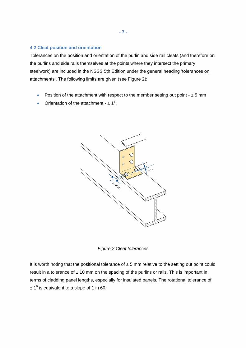
4.2 Cleat position and orientation
Tolerances on the position and orientation of the purlin and side rail cleats (and therefore on
the purlins and side rails themselves at the points where they intersect the primary
steelwork) are included in the NSSS 5th Edition under the general heading ‘tolerances on
attachments’. The following limits are given (see Figure 2):
Position of the attachment with respect to the member setting out point - ± 5 mm
Orientation of the attachment - ± 1°.
Figure 2 Cleat tolerances
It is worth noting that the positional tolerance of ± 5 mm relative to the setting out point could
result in a tolerance of ± 10 mm on the spacing of the purlins or rails. This is important in
terms of cladding panel lengths, especially for insulated panels. The rotational tolerance of
± 10 is equivalent to a slope of 1 in 60.

- 8 -
4.3 Purlin/rail position at mid-span
Tolerances (as opposed to deflection limits) are not normally given for the position of a
member within its length, since this depends not only on the initial out-of-straightness of the
member (a rolling tolerance), but also on its deflection under the action of its self-weight plus
the weight of the cladding. This latter point is an issue for the specifier and is, therefore,
outside the scope of the erection tolerances given in the NSSS 5th Edition.
However, excessive purlin and side rail sag is sometimes a problem for the cladding
community, leading to difficulties on site and potentially compromising the airtightness,
structural integrity and non-fragility of the building envelope. This suggests that there is a
need for tolerances on the mid-span position of purlins and rails, together with guidance on
how these recommendations might be achieved in practice.
As noted earlier, the maximum allowable purlin or side rail sag is governed by the ability to
fix the cladding and achieve an airtight seal. The suggested limits given below in Table 1
are, therefore, dependent on the type of cladding and should be read in conjunction with any
product-specific guidance issued by the cladding manufacturer.
Where built-up cladding systems are used, the provision of a lap between the liner sheets
allows moderate deviations to be accommodated. However, the lack of such a lap in
insulated panels, together with strict end bearing requirements and manufacturing tolerances
on the panel length, mean that greater care is needed to facilitate fixing of the panels to the
purlins or side rails in this case.
The critical tolerance from a cladding contractor’s point of view is the downslope position of
the top flange of the purlin at the time that the cladding is fixed. The recommended
maximum deviation of the purlin is ± x, as illustrated in Figure 3. This tolerance is applied to
the position of the purlin relative to a fixed datum point in order to prevent the build-up of
cumulative tolerances over the length of the roof slope.
- 9 -
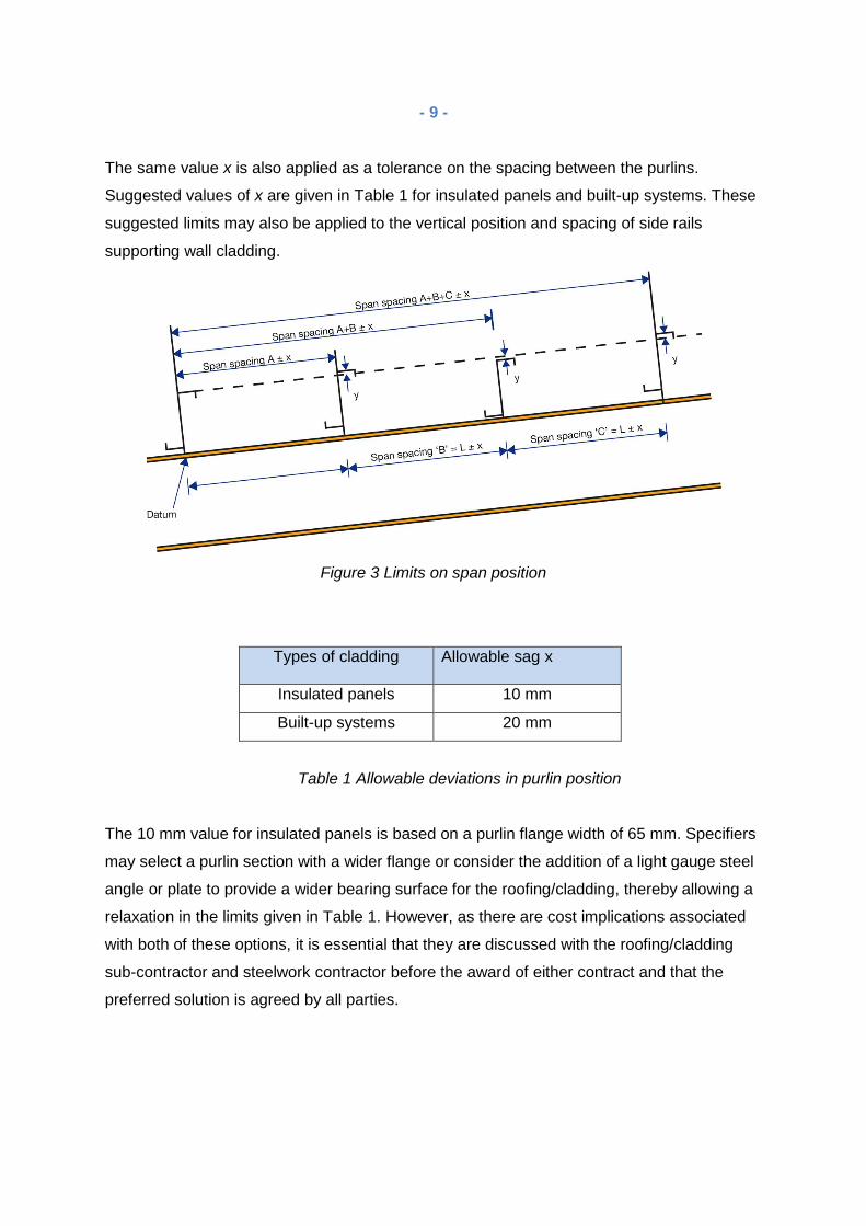
The same value x is also applied as a tolerance on the spacing between the purlins.
Suggested values of x are given in Table 1 for insulated panels and built-up systems. These
suggested limits may also be applied to the vertical position and spacing of side rails
supporting wall cladding.
Figure 3 Limits on span position
Types of cladding
Allowable sag x
Insulated panels 10 mm
Built-up systems 20 mm
Table 1 Allowable deviations in purlin position
The 10 mm value for insulated panels is based on a purlin flange width of 65 mm. Specifiers
may select a purlin section with a wider flange or consider the addition of a light gauge steel
angle or plate to provide a wider bearing surface for the roofing/cladding, thereby allowing a
relaxation in the limits given in Table 1. However, as there are cost implications associated
with both of these options, it is essential that they are discussed with the roofing/cladding
sub-contractor and steelwork contractor before the award of either contract and that the
preferred solution is agreed by all parties.

- 10 -
Rooflights require special consideration, as the fasteners connecting them to the purlins
need to be positioned within a narrow zone around the perimeter of the rooflight. The width
available for the fasteners, and hence the tolerance on the purlins, depends on the type of
rooflight.
The dimension y in Figure 3 is the allowable variation in the top flange level of the purlin with
respect to a datum line running parallel to the rafter. The maximum allowable value of y is
dependent on the type of cladding and, in particular, on its ability to flex without sustaining
damage. Limiting values of y may be obtained from the cladding manufacturers’ technical
literature.
4.4 Purlin rotation within the span
Where built-up cladding systems are specified, the positional requirements for the purlin (see
Section 4.2) should also be applied to the top of the spacer system in order that the outer
cladding sheets may be installed correctly. The alignment of the top of the spacer system is
governed by the position of the purlin and the rotation of the top flange of the purlin relative
to the plane of the roof.
As built-up cladding systems have become deeper, so the effect of the purlin flange rotation
has become more significant. For example, if a purlin undergoes a twist of 30 relative to the
rafter, the corresponding misalignment at the top of a 180 mm deep spacer system is 22
mm, as shown in Figure 4.
In the case of insulated panels, which generally possess a relatively high bending stiffness,
excessive purlin twist could prevent the panels from seating properly on the top flange of the
purlin. This is likely to cause difficulties for the cladding installation contractor and, if the
rotation of the top flange is sufficiently severe, could prevent a proper connection from being
made between the panel and the purlin.

- 11 -
Most standing seam roof systems are sensitive to purlin rotation and the manufacturer’s
recommended rotation tolerance can be as low as ± 10 in some cases.
\Pub\Pub8_off\P346\Text 02-11-2/11/06
Figure 4 Influence of purlin twist on spacer position
4.5 Achieving the required tolerances
There are several potential reasons for the problems that cladding contractors sometimes
encounter regarding the condition of the purlins and side rails, covering a range of activities
from specification to installation. These activities are listed below, together with guidance on
the steps that should be taken in order to avoid poor alignment and excessive sagging of the
secondary steelwork.

- 12 -
4.5.1 Specification
Select a purlin section that will not sag excessively under the action of its own self-weight
plus the appropriate weight of cladding at the time of the cladding installation, taking into
account the proposed span and the provision of anti-sag rods. For the purpose of this
calculation, the weight of cladding should be taken as the weight of the insulated panels or
that of the liner, depending on the chosen cladding type.
Where appropriate, specify anti-sag rods to limit the downslope sag of the purlin. The purlin
manufacturers will normally indicate the spans above which anti-sag rods are needed, but
they should also be considered at shorter spans where particularly tight tolerances are
required.
4.5.2 Manufacture
Ensure that the purlins and side rails are manufactured to the tolerances set out in BS EN
1993-1-3:2006. There should be little difficulty meeting this requirement when the secondary
steelwork is purchased from a reputable supplier in the United Kingdom.
P:\Pub\Pub800\Sign_off\P346\Text 02-11-06.doc Printed 22/11/06
4.5.3 Transport, handling and storage
Take care to avoid damage during the transportation of the purlins and rails to site and when
handling these components on site. Even small deformations caused by handling can cause
difficulties during erection.
Ensure that all steelwork is stored in a safe location (where it will not be damaged by traffic
or site plant) and that it is correctly supported.
4.5.4 Fabrication and erection
Install all attachments to the steel frame, including the cleats for the purlins and rails, in
accordance with the tolerances given in the NSSS and Section 4.2 of this document.
When erecting the secondary steelwork, pay particular attention to the joints between
members to ensure that the surface onto which the cladding is to be attached is straight,
flush and free of lips, steps or other obstructions.
- 13 -
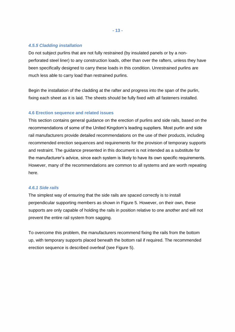
4.5.5 Cladding installation
Do not subject purlins that are not fully restrained (by insulated panels or by a non-
perforated steel liner) to any construction loads, other than over the rafters, unless they have
been specifically designed to carry these loads in this condition. Unrestrained purlins are
much less able to carry load than restrained purlins.
Begin the installation of the cladding at the rafter and progress into the span of the purlin,
fixing each sheet as it is laid. The sheets should be fully fixed with all fasteners installed.
4.6 Erection sequence and related issues
This section contains general guidance on the erection of purlins and side rails, based on the
recommendations of some of the United Kingdom’s leading suppliers. Most purlin and side
rail manufacturers provide detailed recommendations on the use of their products, including
recommended erection sequences and requirements for the provision of temporary supports
and restraint. The guidance presented in this document is not intended as a substitute for
the manufacturer’s advice, since each system is likely to have its own specific requirements.
However, many of the recommendations are common to all systems and are worth repeating
here.
4.6.1 Side rails
The simplest way of ensuring that the side rails are spaced correctly is to install
perpendicular supporting members as shown in Figure 5. However, on their own, these
supports are only capable of holding the rails in position relative to one another and will not
prevent the entire rail system from sagging.
To overcome this problem, the manufacturers recommend fixing the rails from the bottom
up, with temporary supports placed beneath the bottom rail if required. The recommended
erection sequence is described overleaf (see Figure 5).
- 14 -
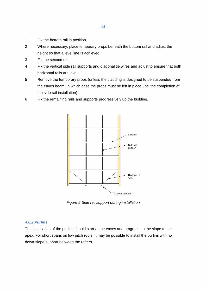
1 Fix the bottom rail in position.
2 Where necessary, place temporary props beneath the bottom rail and adjust the
height so that a level line is achieved.
3 Fix the second rail.\P346\Text 02-11-06.Printed 22/11/06
4 Fix the vertical side rail supports and diagonal tie wires and adjust to ensure that both
horizontal rails are level.
5 Remove the temporary props (unless the cladding is designed to be suspended from
the eaves beam, in which case the props must be left in place until the completion of
the side rail installation).
6 Fix the remaining rails and supports progressively up the building.
Figure 5 Side rail support during installation
4.6.2 Purlins
The installation of the purlins should start at the eaves and progress up the slope to the
apex. For short spans on low pitch roofs, it may be possible to install the purlins with no
down-slope support between the rafters.
- 15 -
Where this is attempted, the steelwork erectors should ensure that the sag at mid-span is
within the recommended limits given in Section 4.3.
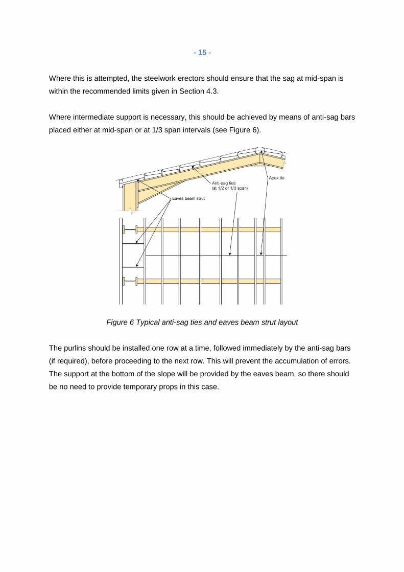
Where intermediate support is necessary, this should be achieved by means of anti-sag bars
placed either at mid-span or at 1/3 span intervals (see Figure 6).
Figure 6 Typical anti-sag ties and eaves beam strut layout
The purlins should be installed one row at a time, followed immediately by the anti-sag bars
(if required), before proceeding to the next row. This will prevent the accumulation of errors.
The support at the bottom of the slope will be provided by the eaves beam, so there should
be no need to provide temporary props in this case.

- 16 -
5.0 CONCLUSIONS
It is important that the installation criteria are set at the design stage and implemented at the
construction stage to ensure that all elements of the construction perform as expected and
also that the interface, interaction and fit between components and systems meet with
expectations.
Without these criteria, the building will not perform correctly and the installation and
attachment of component parts by follow-on trades will be compromised. Follow-on trades
which are contractually responsible for accepting the condition of the earlier works prior to
commencing the installation of subsequent components must ensure that the serviceability
states and deflection criteria meet the design parameters for their products before
proceeding.
Adoption by industry of the guidelines outlined in this document will lead to better and more
consistent standards of metal roofing and cladding construction.
MCRMA member companies can advise on the suitability and performance of materials,
systems and assemblies to ensure that the deflection criteria are calculated properly and
that the cladding and components are specified accordingly. In addition, design information
can be obtained from any of the independent roofing and cladding inspectors featured on the
MCRMA web site at www.mcrma.co.uk

- 17 -
REFERENCES
ACR [M] 001:2014 Rev 5 (Red Book), Test For Non-Fragility of Large Element Roofing Assemblies
BS EN 1993-1-3:2006, Design of steel structures. General rules. Supplementary rules for cold-formed members and sheeting Health and Safety Executive, Manual Handling Operations Regulations 1992 (as amended), Steel Construction Institute, National Structural Steelwork Specification for Building Construction - 5th Edition CE Marking Version Steel Construction Institute P346, Best Practice for the Specification and Installation of Metal Cladding and Secondary Steelwork
USEFUL PUBLICATIONS MCRMA guidance document GD13 Non fragility of roofs - a checklist
MCRMA guidance document GD20 Guidance document on serviceability states and deflection criteria ACKNOWLEDGEMENT This guidance document has been adapted from chapter 4 of the Best Practice for the Specification and Installation of Metal Cladding and Secondary Steelwork, Steel Construction Institute publication P346. For more information visit www.steel-sci.org MCRMA gratefully acknowledges the permission of the Steel Construction Institute to reproduce this content.
DISCLAIMER
Whilst the information contained in this publication is believed to be correct at the time of publication, the Metal Cladding and Roofing Manufacturers Association Limited and its member companies cannot be held responsible for any errors or inaccuracies and, in particular, the specification for any application must be checked with the individual manufacturer concerned for a given installation. Information provided by the MCRMA or contained within publications and articles which are made available in any form (mechanical, electronic, photocopying or otherwise) cannot be used or cited as a means of ensuring that a material, product, system or assembly is compliant with Building Regulations.
©2016 MCRMA - 106 Ruskin Avenue, Rogerstone, Newport, South Wales NP10 0BD
Tel: 01633 895633 [email protected] www.mcrma.co.uk