Guidance Document for Site Erection of Precast Elements · Employees or contractors involved in...
36
Guidance Document for Site Erection of Precast Elements
Transcript of Guidance Document for Site Erection of Precast Elements · Employees or contractors involved in...

Guidance Documentfor
Site Erection of Precast Elements


Contents
Introduction 2Assembly Contractor and Employees 3 General 3 Written Instructions 4 Mandatory trainings 4 Special Elements 4 Control Points 5 Crane Signallers and Riggers 5 Training and Workplace Assessment 5Temporary Storage 6Lifting of Elements 7 Transport Anchors permitted for Hoisting 7 Lifting Equipment 8 Inspection 8 Shackles 8 Lift Mandrels 9 Lifting Scissors and Eye Bolts 9 Lifting Yoke / Assembly Winch 10 Clamping Bracket 10 Loops 11 Loop of Steel Wire Ropes 11 Round Slings / Lifting Slings 12 Chain Sling 12Assembly Equipment 13 Crane Choice 13 Communication 13 Common Lifting 14 Working at Heights 14 MEWP 14 Personal Trasport with Crane 15 Ladders 15 Scaffolding 16Support Equipment 17 Support Devices 17 Handling Support Equipment 18 Fastening Sleeves and Screws 18Rails, Covering and Barriers 19 General 19 Attachment of Balusters 20Personal Safety 21 Personnel Protection Equipment 21 Fall Protection 21 Safety Lines 21 Retractable Belts and Fall Tackles 21 Fall Absorber 22 Security Slings 22Assembly 23 Fastening and Hoisting 23 Pillar, Clamped Pillar, Pendulum Pillar 24 Beams and Support 24 Facades and Walls 25 Turning of Elements 25 Asymmetric Elements 26 Assembly of Railing Brackets, Rails, Covers etc. 26 Support Equipment 26 Removal of the Support Equipment 27 Ceiling Elements 27 Rib Roof Panels (TT and TTS) 28 Rib Roof Panels 28 Corrugated Sheets 29 Welding 29 Other Construction Activities during the Element Assembly 30 Dismantling of Elements 30Tables 31
1

Introduction
The purpose of the CRH Europe Heavy-/Lightside Standards is to ensure that proper guidance is provided for the implementation of the 16 Life Saving Rules across our companies.
Although in many companies procedures already exists, centrally developed Standards can help in addressing the topics of the 16 Life Saving Rules in more detail as they reflect the CRH Europe Heavy-/Lightside approach of the Life Saving Rules. And, in case procedures have not been implemented in a company, the Standards will form the basis for developing your own company procedures.
The procedures described in these Standards should be reflected in your company procedures: when your company is audited, the Standard will be used as a reference guide.
This Standard is dealing with Life Saving Rule 11: Lifting Operations
When this Standard is applied your employees and contractors will have proper knowledge about what safety precautions should be taken during the assembly of elements during construction and the transport of elements to the construction site.
For you as a manager of the company, it must be clear that you are responsible for implementing the proper tools, training and supervision and that all of your (relevant) employees and contractors are aware of the dangers of site erection of precast elements.
2

Assembly Contractor and Employees
Assembly contractor and employees General Written instructions Special Elements
Crane Hand Instruction and work place assessment
Start-Up Phase
Assembly Contractor and EmployeesGeneral Prior to the assembly there must be held a kick-off meeting where all involved, including crane company, participates.All decisions and agreements reached at the kick-off meeting must be documented in the start-up phase.At the kick-off meeting, you must ensure that the contracting company is able to show proof of training requirements.The kick-off meeting should not be mixed with the general start-up meeting at the construction site, where all the companies that are involved in construction works are represented. Start-up meetings should be repeated when new employers or subcontractors enters the site. The purpose of the general start-up meeting is that everyone gets the best possible knowledge of the common safety work at the site.
The kick-off meeting has to agree as minimum the following topics:• Time- and process plans• Interfaces / coordination between actors• Clarification of who is responsible for the establishment and maintenance of traffic and access roads• Clarification of who is responsible for establishing and maintaining common security • If there are special risks• Review and complete plan for health and safety• Guidelines for the transfer and change of contracts • The possibility of using the planned technical aids• Extent of winter measures: which measures have to be undertaken and who is responsible.
Specific topics to be reviewed and agreed on:• Supplier’s instructions (focusing on specific elements and element weight)• This Site Erection guidance• Receiving items from the supplier; for instance times of delivery• Delivery and assembly sequence• Control points for receiving and assembly• Stabilization of the individual elements• The total temporary bracing (shoring plan)• Installation of temporary fencing and hedges• Use of technical equipment eg lifts, mobile scaffolding, ladders, cranes and element supports• Lifting gear, bolts and anchors• Crane priorities (applicable when cranes operate on different levels in the same area)• Maintenance and inspection of technical equipment and lifting gear• Who is allowed to discard an item• Assembly and dismantling of large element supports and transport out of buildings.
3

Assembly Contractor and Employees
The following should be discussed with crane operators and crane hands:
• Crane location and consolidating surfaces on site.• Lifting zones - burdens must not be passed over working
and seating areas, where there normally are people.• Information concerning:
◦ Crane radius. ◦ Use of lifting equipment (require special attention - see instructions). ◦ Other cranes in the area. ◦ Communication between fitter and crane operator (hands-free radio set can be recommended). ◦ Agreements for the hand signals. ◦ Demarcation of areas in the periods in which there frequently are cranes in use.
Written Instructions Based on the start-up meeting, the contractor ensures that written instructions are available. A risk assessment will be used to determine if all available risks are addressed and control measures are in place.
Written instruction should include:• Information on components and structures• Assembly order to assure the building stability during the construction phase and temporary bracing can take place• Curing times (eg indication of when temporary shoring can be removed)• Various manuals.
For rigger safety, and to ensure that the right equipment is in place, there should be a list of which lifting gear is to be used.
Mandatory TrainingsEmployees or contractors involved in site erection operations (crane operator, rigger and signaller, MEWP operator) must be appointed and trained. It is recommended that this person completed the course provided by an accredited trainer and rewarded with a certificate. Persons without the necessary training or education are not allowed to work as crane operator, rigger, signaller or MEWP operator.
Special Elements Special items require special precautions and extra attention.The supplier must make a clear labeling of specific elements on the element drawing or assembly plan, including:
• Information on temporary stabilization, including requirements for stiffening and anchorages• Information on the lift bracket and hooking.
Special items can be:• Elements that differ from the main supply - eg massive- or pas elements• Beams with the risk of tilting due to uneven loading or height• Slabs with recesses• Elements with shifted center of gravity such as sandwich elements and elements with large recesses• Start and end elements• Very large items• Elements that must be reversed• Staircase elements.
4

Assembly Contractor and Employees
Control Points There have to be defined control points for receiving and assembly of every element type. It can be agreed with the supplier, that special control points are indicated on the packing slip or the item’s label. A procedure should be in place which covers the hierarchy of control when a default in the element is discovered; roles and responsibilities should be defined.
Control points could be:• Visible cracks in casting, e.g. on the inner side of ceilings.• Affixing of the ceiling reinforcement (visible reinforcement on the end surface).• Non-stressed concrete – see end surfaces/concrete nests.• Minimum requirements on abutments (markings on abutments).• Whether or not transport anchors are free of defects and not mounted too closely to the openings.• Transportation damages.• Optical control of fastening means.• Numbering of the elements in keeping with the assembly plan.• Unloading sequence, taking into consideration the stability of the truck during unloading.
Crane Signallers and RiggersControl points for crane signallers and riggers while performing their tasks:
• Minimum amount of overlay of concrete beam / slab• The lifting brackets are undamaged and not located nearby recesses• Transport damage• Numbers of elements that refer to the numbering plan / assembly plan• Unloading order for the sake of the truck’s stability during unloading as well as the use of a stable unloading place.
Training and Workplace AssessmentThe company is committed to training its employees and to developing a written workplace assessment in collaboration with the health and safety organization, which ensures that all relevant health and safety issues are covered by the employment protection measures of the company.
The work is to be planned and executed according to the instructions in the industry guide and the instructions of the supplier. The employee must be informed about it in the introductory meeting before the acceptance of the work.
5
Temporary Storage
Temporary Storage Frame Transporter and A-Frames Inloader
Interim Storage
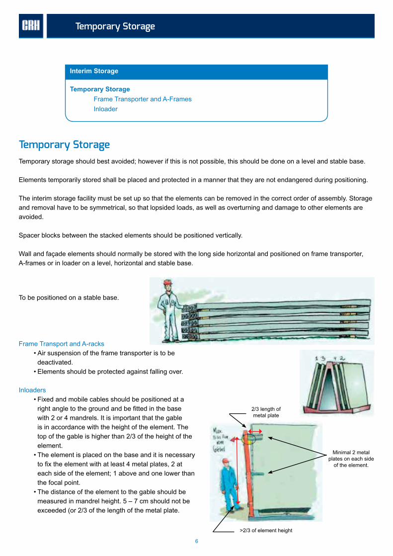
Temporary StorageTemporary storage should best avoided; however if this is not possible, this should be done on a level and stable base.
Elements temporarily stored shall be placed and protected in a manner that they are not endangered during positioning.
The interim storage facility must be set up so that the elements can be removed in the correct order of assembly. Storage and removal have to be symmetrical, so that lopsided loads, as well as overturning and damage to other elements are avoided.
Spacer blocks between the stacked elements should be positioned vertically.
Wall and façade elements should normally be stored with the long side horizontal and positioned on frame transporter, A-frames or in loader on a level, horizontal and stable base.
To be positioned on a stable base.
Frame Transport and A-racks• Air suspension of the frame transporter is to be
deactivated.• Elements should be protected against falling over.
Inloaders • Fixed and mobile cables should be positioned at a
right angle to the ground and be fitted in the base with 2 or 4 mandrels. It is important that the gable is in accordance with the height of the element. The top of the gable is higher than 2/3 of the height of the element.
• The element is placed on the base and it is necessary to fix the element with at least 4 metal plates, 2 at each side of the element; 1 above and one lower than the focal point.
• The distance of the element to the gable should be measured in mandrel height. 5 – 7 cm should not be exceeded (or 2/3 of the length of the metal plate.
2/3 length of metal plate
Minimal 2 metal plates on each side
of the element.
>2/3 of element height
6

Lifting of Elements
Transport Anchors permitted for Hoisting Hoisting Screws/Inserts
Hoists Examination Crane and Hoisting Hooks Shackles Lifting Mandrels Lifting Scissors and Eye Bolts Lifting Yolk/Assembly Winch Clamping Bracket Loops etc. Loop Rope from Steel Wire Round Sling/Lifting Bands Chain Suspensions
Hoisting of Elements
Lifting of ElementsOnly unsecured elements should be lifted. Lifting must be done vertically. An exclusion zone needs to be installed during lifting and assembly of the element. No person is allowed within this zone during lifting and assembly.
If possible, the elements should be directly assembled from the frame transporter, A-frame or internal loader. Special elements, such as pillars that cannot be mounted directly from the cart may have to be mounted immediately after being set on the floor.
The supplier shall provide information on the weight of the elements, the lifting points, loop angle, etc. The information may be shown on the element drawings and / or directly on the element.
When lifting the elements, loops etc., should be adjusted in length, so that the element during the assembly is at the same time connected to any supports, or positioned as desired.
Transport Anchors permitted for Hoisting The elements may only be lifted on the embedded anchors provided for this. Some embedded anchors are only intended for pulling in one direction (vertical or oblique). This must be checked.
The instructions of the supplier regarding theinclination angle (angle loop) should always befollowed, since the embedded anchors aredesigned for it.
7

Lifting of Elements
Embedded anchors, which are deformed or damaged (for example, by pulling in the incorrect direction), may not be used. If necessary, special measures as directed by the site manager, the supplier of the elements, or other responsible person shall be taken so that the element can be properly hoisted and assembled.
Lifting Equipment All lifting gear must be CE marked, also the lifting points in the elements, where they arebpart of a lifting system (and marked as such).Remember that the employees must be instructed in accordance with the manufacturer’s instructions for use of the lifting that will be used, and that the relevant instruction manual must be available on the site.
All lifting brackets and other lifting gear should be clearly marked with a safe working load or WLL. This marking will clearly outline the maximum allowed load that can be lifted with this equipment.
Crane and lifting hooks and shackles can also be marked with the chain / hook dimension. Depending on the type of equipment, the labeling must be stamped / painted on, or the equipment can be provided with a sign / name plate or sticker.
The equipment must be kept clean.
InspectionBefore use, the lifting equipment shall be visually inspected. Damaged lifting equipment must be disposed directly, it is not allowed to use damaged lifting equipment.
Lifting equipment and its components must be regular inspected according to the companies procedure. The companies procedure should at least meet the local legislative requirements as well as the CRH requirements.All lifting equipment in use must have a rated capacity tag and evidence of the date of last inspection. A documented color coding system is required.
ShacklesShackles should be marked. Industrial shackles should NOT be used. The screw should only be screwed lightly by hand, in order to prevent harmful tension in the bracket. Bolts and nuts should ALWAYS be secured with a splint.
8

Lifting of Elements
Lift MandrelsLift mandrels must correspond to the lifting hole in the element and the element weight, and be secured so that the loop cannot slip off.
Loop/chain must be as lifted as closely to the element as possible, so that the mandrel does not bend - use spacer tube.
• Mandrels with a weight of max. 12 kg are to be removed from the ladder.• Mandrels which require technical aids are to be pushed through the pillar by the head, if the weight/the frictional
resistance is too large.
Lifting Scissors and Eye BoltsFor the fitting of hoisting bolts and permitted screws. It should be noted that the nut or bolt head provides sufficient contact surface. Only eye bolts, ring nuts and fixed ring bolts from recognized manufacturers, which are marked with SWL/WLL may be used.
Avoid the use of rolled thread in combination with cut thread.
NOT OK OK
9
Lifting of Elements
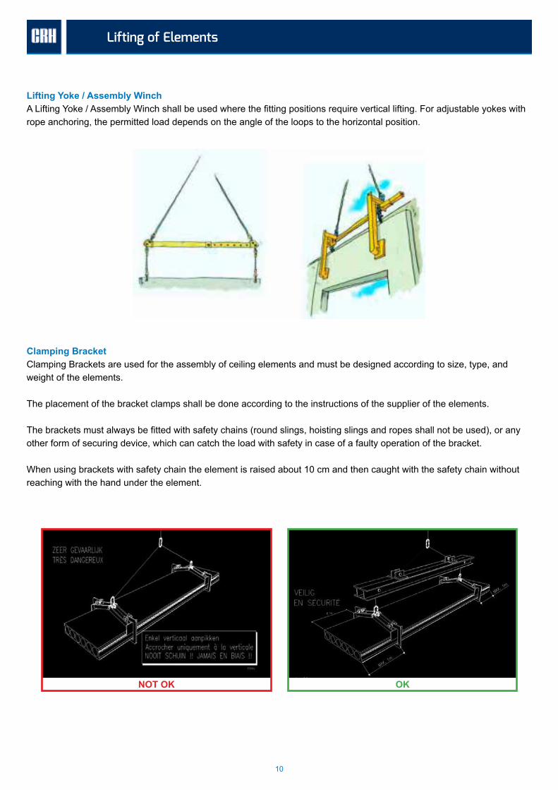
Lifting Yoke / Assembly WinchA Lifting Yoke / Assembly Winch shall be used where the fitting positions require vertical lifting. For adjustable yokes with rope anchoring, the permitted load depends on the angle of the loops to the horizontal position.
Clamping Bracket Clamping Brackets are used for the assembly of ceiling elements and must be designed according to size, type, and weight of the elements.
The placement of the bracket clamps shall be done according to the instructions of the supplier of the elements.
The brackets must always be fitted with safety chains (round slings, hoisting slings and ropes shall not be used), or any other form of securing device, which can catch the load with safety in case of a faulty operation of the bracket.
When using brackets with safety chain the element is raised about 10 cm and then caught with the safety chain without reaching with the hand under the element.
NOT OK OK
10

Lifting of Elements
Loop of Steel Wire Ropes Loops should be fitted with eyelets with pressed safety ropes manufactured in special workshops. If screw caps are used, the supplier’s instructions should be followed.
The specified load capacity applies to single loops for vertical lifting.
The load capacity of composite loops is dependent on the angle between the loops. In the rolling out of long loop of steel wire ropes: Avoid kinking, as these may damage the steel rope during tightening.
LoopsThe load of loops and chains is dependent on the inclination angle.
The length of the loops can be calculated from the distance between the sling point and the angle of inclination.
For fastening with 4 loops, the load should be calculated only for two loops, i.e. the whole load must be able to be absorbed by the two parts and the associated embedded transport anchors, unless during the fastening it is ensured that the weight of the element is distributed to all four parts. This can, for example, take place with the aid of compensation triangles.
For the fastening of 2 parallel parts no double bearing capacity is achieved by the use of a double loop set (it is not certain that the loops have the exact same length).
11

Lifting of Elements
Number of strips
Chain diameter
Date: No:
Round Slings/Lifting Slings Slings made of synthetic fibers should not be used in high mechanical stress or excessive heat and cold stress. Protect from direct sunlight.
The safe working load (SWL), etc. of slings and round slings made of synthetic fibers is indicated on a sewn label. In addition, the SWL load for some slings is indicated by color code (color of the bands) and/or by woven black longitudinal strips (1 strip per ton of load capacity).
The angle of inclination must not exceed 60 degrees.
Chain Sling For hoisting, only chains with certificate may be used.
The chain should not be twisted in the loaded state and should not have any “knots”. The shortening should be performed using a shortening claw with safety device.
The angle of inclination must not exceed 60 degrees.
12

Assembly Equipment
Crane Choice Communication Common Lifting
Working at Heights Personnel Lifts Personnel transport with crane Installing the baskets
Ladders Positioning of ladders Working on ladders at 5 to 10m heights Ladder as access
Scaffolding
Assembly Equipment
Assembly EquipmentA good and safe workplace requires proper equipment. This ensures a stable and secure assembly. Defective equipment should therefore never be used. Damaged ladders, scaffoldings, supporting devices, elevators, etc., should be removed as soon as possible from the site. In unacceptable weather conditions (strong wind or precipitation) assembly should be ceased. However, it is to be ensured that all elements are properly supported.
Crane Choice The weight of the elements can have a tolerance of + / - 10%. The crane must therefore also display a lifting capacity that allows - even at maximum reach - the lifting of all the elements and hoists and placing them in the correct position.
Communication The communication between the crane hands and crane operators must be reliable:
• Recognized signals are to be used with eye contact between crane hands and crane operators.• In cases where crane operators and crane hands cannot see each other, radiotelephone equipment should be
used. A signal man can also be used for repeating the signals of the crane hand.• Pictures indicate international signals as example. Please note that local signals could differ from this example.
Lift Lower Move Stop! Stop Quickly! I did not understand
13

Legally prescribedsafety checkperformed
Assembly Equipment
Common Lifting The common lifting with two cranes is to be planned carefully and be guided by a competent person who clarifies misunderstandings between both crane operators. Both cranes should be identical in construction and should ideally have the same velocity regulation. The load must never exceed 75% of the capacity of each crane. If necessary, special equipment must be used to ensure proper weight distribution and vertical lifting.
Working at Heights During assembly, work is often done at heights. The following can be used for this:
• MEWP’s• Personnel transportation with crane• Rolling scaffolding• Ladders
MEWP’s are the safest and most widely used method.
Personnel transport by crane may only be done at high altitudes or where the use of MEWP’s is not possible. In both cases, the requirements for setting up and operating on the access equipment will be provided.
Scaffoldings are usually only used where there is a stable floor like concrete floor/floor plate.
MEWP MEWP’s may be used regardless of the working height during assembly, fastening and supporting. The movements of the MEWP should be controlled from the basket. Personell inside the basked should be secured with a harness and lifeline.
MEWP’s should be used, tested and maintained in accordance with the manufacturer’s instructions. These instructions must be accessible on the personnel lift.
14

Assembly Equipment
Personnel Transport with Crane The basket is suspended on a fixed rack or 4 loops/chains, which are attached at least in 1 meter height. The weight of the basket and contents must not exceed 1000 kg, which does not exceed 25% of the lifting capacity of the crane. The lifting and lowering speed of the crane shall not exceed 0.3 m/s. There must be a radiotelephony link between crane and basket. Please consider the use of a crane basket as a last resort, the use of this type of equipment will not be encouraged. If a man basket is used all arrangements should be aligned with your local legislation.
Installing the Basket:
• The rail around must be at least 1 m high and from hand, knee and made of 15 cm skirting.
• An extra hand bar 10 cm above and 10 cm within the upper edge.• The door must open inwards.• The maximum load must be visible at the entrance.• When working in 3D-lifts and crane baskets, a fixed safety harness should always
be attached to a special attachment point. For personnel transport by crane, the attachment point must be located on the crane hook or another component fixed to the hook.
Ladders The use of ladders offers the least safety and should therefore be limited. Before the ladder is used it should be visually inspected on damages. A damaged ladder can’t be used. All ladders should be inspected on a regular basis.
Placement of ladders Ladders should always be properly set up, i.e. on a solid flat surface at an angle of 60-70 degrees with anti-slip protection on the ladder. It has been advised to secure the ladder to the object it is leaning on and to install an object in front of the ladder to avoid the ladder slipping away. In some countries this is mandatory by law.
Working on ladders
• Carry only lightweight and easily manageable loads, such as drill, ceiling connections, supporting devices, etc.
• Only one-handed executable activities may be executed.• The field of activity may not exceed an arm’s length - do not lean to the
side!
15

Assembly Equipment
Ladders as AccessShould be affixed and tower 1 meter above the access point. Fall protection should be installed on the edge to prevent falling down while accessing/ exiting the ladder.
Scaffolding All scaffoldings should be erected according to the supplier’s assembly instructions. This should include information on the requirements for bracing and for what the scaffolding may be used.
The scaffolding and any work platform above the height of 2 meters must be fitted with a 1 m high rail, consisting of hand, knee and foot skirting as well as scaffolding floor in full length and width. Erection and inspection of scaffolding has to be in line with local legislation and requirements in the 16 Life Saving Rules.
All wheels must be locked when working on a mobile scaffold. The presence of persons on the mobile scaffolding is prohibited during the movement of the scaffolding.
16

Support Equipment
Support Devices Basically all elements/pillars should be braced with at least two supports, unless the consultant/supplier specifies otherwise. The supports should be anchored to the fastening sleeves embedded in the element/in the pillars, and sufficiently fastened with expansion bolts (usually class 8 steel) to the concrete foundation, flooring, or floor plates.
With the support in hollow ceilings, it is important to note:
• Whether or not the hollow ceiling can hold the supporting forces.• That the expansion bolts are mounted in the ribs of the ceiling or in the
hardened concrete joints.
Telescopic supports cannot be extended so far that the splint is no longer covers the inner tube. The supports must not be unscrewed longer than prescribed.
The supplier/importer of concrete elements shall disclose requirements for the support, in the assembly guide or on his erection drawing. This information serves the selection of the properly designed support devices and screws.
If other influences affect an element which is importance for the support, but which is beyond the knowledge of the supplier, this must be considered when configuring the support.
The supports shall not be removed prior to the final stabilization of the building or possibly of a construction phase, unless the project manager or the supplier grants approval for this.
Support Equipment
Support Equipment Support Devices Handling Support Devices Fastening Sleeves and Screws
Support Equipment
17

Support Equipment
Handling Support Equipment Support equipment with weights up to 25 kg can be manually handled by one person unless local legislation indicates otherwise.
Support devices having a weight 26 to 45 kg can be manually handled by two persons.
Support devices weighing more than 45 kg should be handled with the help of technical aids, such as a crane.
When removing restraints of more than 45 kg, special care must be taken because this normally would not be removed by an assembly crane. Deemed as correct if:
• The supports are removed by a lift and lowered along the wall, the movement being controlled simultaneously with the help of a rope from the basket, (no one is allowed under the support after removal of the splint and after lowering has started) or
• Where space permits (such as in large halls, etc.) technical aids such as a tractor or truck crane may be used.
Fastening Sleeves and Screws Fastening sleeves and screws (usually class 8 steel) shall be designed in a manner that they correspond to the size of the elements, and it is to be ensured that the assembly contractor has all the important information about the holding capacity, strength, etc.
18

Rails, Covering and Barriers
Rails, Covering and Barrier General Fastening of Balusters
Rails, Covering and Barriers
General Rails, covering, and barrier are important safety precautions during assembly to prevent people from falling from heights. Therefore, the safety precautions must be taken as early as possible.
Fall protection is mandatory from a height of maximum 2.5 meters or lower if local legislation indicates otherwise.
In story buildings the rails along the façades must be adjusted so that the opening for mounting in front is as small as possible.
For some jobs, this can be achieved through the mounting of “permanent” posts on the façades/bars and of posts for mounting the rails on ceiling elements.
Rails, Covering and Barriers
The barrier installed must have two guard rails (at hip and knee height) and a toe board must be installed.
Rails along the edges are not necessary if the work or access occurs more than a minimum of 2 meters away from the edge. If local legislation requires a higher standard the local standard should be followed. In these cases, a clear and durable marking must be done, for example, with cones and boards. Plastic band is not durable enough and therefore must not be used.
19

Rails, Covering and Barriers
Door openings, elevator shafts, holes, etc. in floors and floor slabs are also to be fitted with a rail or covered immediately after the emergence of the holes (if this is not done before the assembly).
Covering of the holes should be done by preference before the elements are delivered, if this is not the case, the covering (or the attachment of a rail) should be done immediately after the mounting of the individual elements.
The coverings are either to be screwed/push firmly or be secured against displacement by slats at the bottom.
Attachment of Balusters The supplier of rails/balusters should provide mounting instructions. The size and quality the screws to be used should be derived from the instructions. Commercial screws must not be used. In case wooden rails are used it must be assured that the wood is free of defects.
20

Personnel Protection Equipment
Personal Safety Personnel Protection Equipment Fall Protection Safety Lines Retractable Belts and Tackles Fall Absorber Security Slings
Personal Safety
Personnel Protection Equipment
Personnel Protection Equipment When working in assembly, a helmet, high visibility safety vest and safety shoes must be worn.
Eye protection should be worn when mandatory on site or indicated by the risk assessment:
• Welding goggles or face protection during welding.• Goggles or Visor when working with the angle polisher and during hacking, drilling, or cutting.
The dust from concrete, brick and other stone products is harmful because it contains reparable crystalline silica.If the dust cannot be removed at the source, a dust mask or other breathing apparatus should be worn.
Fall ProtectionThe attachment point for fall protection equipment must be able to withstand a pull of at least 10 kN (1000 kg). Safety LinesSafety Lines should be made of steel wire so that they cannot be cut by sharp concrete edges.
Retractable Belts and Fall TacklesRetractable Belts and Fall Tackles function like retractable belts in the car do. Whenever possible, a short safety line or a slight retractable belt - possibly combined with a security sling - should be used.
If more movement space is needed, a fall tackle should be used. However, some fall tackles only work if they hang vertically, such tackles should, therefore, should be fixed vertically to the place of work. Other fall tackles must bemounted such that the “pendulum effect” is avoided.
21

Personnel Protection Equipment
Fall AbsorberA Fall Absorber functions as a brake during a crash. Investigate the length of the line and fall absorber, you might need to use a shorter line.
Security SlingsSecurity Slings are steel wire ropes that are stretched along a rib roof panel. A short safety line is attached to this with snap hooks in order to move around on the roof. If two persons, who are attached to the same security sling, have to pass each other, at least one person must have a second safety sling, so he can get around with always at least one sling attached.
22

Assembly
Assembly Fastening and Hoisting Pillars Clamped Pillar Pendulum Pillar Beams and Supports Facades and Walls Elements with Inserted Ceilings Turning over of Elements Assembly of Rail Holders, Rails, Covering, etc. Support Devices Distance of the Support Devices Ceiling Elements TT and TTS Support Corrugated Ceiling Sheet Corrugated Sheet Metal Welding Other construction activities during the Element Assembly Dismantling of Elements
Assembly
Elements, pillars, ceilings, etc. are to be delivered in the correct order of assembly. If this is not the case, it must be decided whether the items should be reloaded or returned. In unforeseen situations (when the items have beenunloaded, for example, in the wrong order), which may affect the safety, the groups of the project engineer and/or erection manager including the safety team must be consulted to find an acceptable solution.
Special elements must be marked, and their Assembly must be discussed at the introductory meeting.
Assembly
Fastening and HoistingThe fastening can be done from a ladder or from an element. Before the lifting of all elements, pillars, ceilings, etc., the crane hand must have left the element, and it is to be ensured that when lifting, while floating in the air and the assembly that no one is in the line of danger.
23

Assembly
PillarBefore assembly, the support of the pillar’s base plate, must be of adequate strength. Unload the pillar on the ground, attach lifting equipment it, hoist it upright and mount either directly on the foundation (pendulum pillar) or imbedded (clamped pillar). The pillar is placed on leveled fiber blocks, on metal plates, on a bolt head or embedded in a molded cushion.
Pendulum PillarPendulum pillars should has to be stiffened by two supports, attached in the 2/3-point, in a right angle towards to each other. It must be ensured that the column can’t rotate while it is braced. Element supports should only be removed after casting has hardened, or when the pillars are loaded – i.e. are supported from above, for example, by a beam.
Beams and Support Before beams or supports are mounted, ensure that the pillars/elements which they should support are supported or permanently cast/are supported and the concrete has the necessary strength.
The crane should be able to bear the beams/supports until they are swung into place. Tall slender beams (H > 4xB or L > 60xB, B = top width) and soft movable support (neoprene or similar), are necessary to secure against tipping over before the uncoupling.
For eccentrically loaded beams there is a risk that the beam may tip over when the load is increased. Such beams are to be marked as special elements and secure from tipping over.
Clamped PillarClamped pillars should be mounted in the recess and wedged with hardwood wedges. Pillars without mandrel must be secured against falling with the use two element supports, positioned at a right angle to each other. Element supports should only be removed after casting has hardened, or when the columns are loaded - i.e. are held, for example, from above by beams.
24

Assembly
Facades and WallsDuring the assembly of façade elements in the work on storey buildings, the work must be performed from the uppermost floor plate, and, if necessary, specific module should be dismantled for mounting the rails. If rail posts are mounted between two elements, the rails should be removed to the extent required.
In order to prevent an uneven weight of the frame transporter, loadingshould be done symmetrically.
The crane should bear the element until it is positioned and thesupports are mounted.
If additional protection against overturning is usually required, for example on both sides of the element in the angle iron screwed in the foundation, support the mandrels on the bottom or horizontally. Diagonal supports should be designed so that they can withstand the wind load.
Turning of ElementsIf elements should be turned over before assembly, the crane must be equipped with two independent hoists and fitted with a pulley.
It should be noted that the lower lifting anchor on the longitudinal side bears a large part of the load. Hooks, loops, etc., are, therefore, should always be laid out according to the instructions of the supplier of the elements.
25

Assembly
Asymmetric ElementsAsymmetric elements are to be marked as special elements and their assembly/support is to be discussed at the introductory meeting.
When turning asymmetric elements, it may be necessary to temporarily support the “free corner”.
During the assembly of façades and wall elements with large cut-outs, for example a door hold in two adjacent elements, particular caution should be exercised, especially if the elements are not quite vertical after turning.
Oftentimes the additional bracing/supporting of the “free corner” - of either one or both elements - is required. Rails and covers for the subsequent roofing work or for the continuation of construction into the heights should be installed as soon as possible after the construction process.
Assembly of Railing Brackets, Rails, Covers, etc. Rails and covers for the subsequent roofing work or for the continuation of construction into the heights should be installed as soon as possible after the construction process.
Support Equipment All elements are to be double supported. Basically two supports are to be mounted on 2/3-points of each element, but 2 supports for the first element and one support and a ceiling connector can be used for the subsequent element. If only one support is used, it must be able to bear the full load of the elements.
The load-bearing elements must be sufficiently supported (for example spacers) or supported and hardened before being “built upon”.
If non-structural elements are supported on ceilings/ceiling plates, is to be ensured that the ceilings/ceiling plates can transmit forces to the foundation. If this is not the case, temporarily support must be provided, for example with supports.
The Assembly of non-load bearing façades and walls (excluding gables) occurs from underlying floor plate.
26

Assembly
Removal of the Support EquipmentSupports may only be removed when the final building stability is achieved and the cast base etc., are hardened, unless an authorized person grants the permission to do so.
Ceiling Elements Before ceiling elements are fitted, the base of the sup porting structure must be moulded and hardened or the necessary load bearing capacity must be ensured by other means.
The first ceiling element should be positioned from a lift, a ladder or from the scaffolding. The subsequent elements should be positioned from the last assembled ceiling element.
Is the height of fall along the wall 2.5 m or more (or when local legislation indicates otherwise), when the first ceiling element is positioned, a rail should be attached along one side, at the ends of the element.
If the rail is not attached prior to the fitting of the ceiling elements,it must be continuously fitted in such a way that it can be easily moved to or beyond the front of the assembly.
If the fall height is more than 2 / 2.5 m (depending on local legislation) at the assembly front, a protection against fall, for example a security sling should be used.
27

Assembly
Holes in the ceiling should always be covered as quickly as possible,i.e. preferably prior to the element leaving the factory. If this is not the case, the covers have to be made immediately after the mounting of the individual elements.
If 2 or more parts have to be mounted side by side, the parts must be mounted parallel to each other.
During the winter months snow and ice from theelements must be removed before they are hoisted.
Rib Roof Panels (TT and TTS)Before TT and TTS supports are mounted, the base of the supporting structure must be mounted and hardened or the required bearing capacity must be ensured by other means.
A During the lift, you can use a control rope, from a lift or ladder, to guide the elements controlled to its position.Lift / ladder should not be placed under the element during assembly. You must not leave the lift uncontrolled, while unhooking. If necessary, you must use appropriate PPE.
Rib Roof Panels Closely mounted ribs roof panels are to be mounted exactly as ceiling elements. Otherwise, applies to the Assembly of ribs roof panels the same as for TT and TTS support.
28

Assembly
Corrugated SheetThe fastening of corrugated sheets takes place on the ground, and the sheets are lifted to the mounting location using a special bracket. During assembly, a security sling is to be used.
It is required that a rail is mounted along the gable and at the ends of the first TT or TTS support. Afterwards the first row of corrugated sheet is mounted and the rail is continued until the next assembly area.
If narrow straps have been placed, the rail is attached gradually depending on the post spacing or façade module.
Skylight holes or the like are to be covered - always using a security sling - before the assembly of the next row of corrugated sheets takes place.
WeldingTo avoid shifts and to ensure the plate-effect, the
• carrier compound• connections between beam and pillows• corrugated sheet and TT or TTS-carrier• gable and ceiling elements
should always be welded gradually prior to removal of the temporary support.
29

Assembly
Other construction activities during the Element AssemblyThe part of the building above which the element is directly mounted may only be accessed or worked in if two floors which have already been cast are between.
Dismantling of ElementsSometimes it is necessary to dismantle one or more concrete elements during construction, without this amounting to a demolition.
In these cases, the temporary stability is as important as safety during assembly. The dismantling of elements has to be done according to instructions in this industry guide, only in reverse order, for example:
1. Securing an element with supports (neighboring elements, among other things may need to be secure as well).
2. Detach element.3. fasten on and tighten.4. Remove the supports.5. Lift the element.
Before disassembly of elements, a designer whit knowledge on the building structure should be consulted.
30

Tables
If the load hangs at an angle, because the focus is not exactly between the attachment points or because a rope is shorter, so that the element for positioning at different heights (for example, stairs) hangs correctly, the load on the one loop can be considerably more. This should be considered when selecting the loops. It is also to be ensured that the lifting anchor of the element is designed for higher load.
Tables
31

Tables
32

Tables

Version 3-3-2016