GUI Based Industrial Monitoring and Control System Based Industrial Monitoring and Control System...
4
2014 Power and Energy Systems: Towards Sustainable Energy (PESTSE 2014) GUI Based Industrial Monitoring and Control System Sadeque Reza Khan Dept. of Electronics and Communication Engineering National Institute of Technology Karnataka [email protected] Abstract-Over the years the Graphical User Interface (GUI) based systems are becoming accepted by the users to interact with electronics environment through graphical icons and visual indicators. In the industries GUI based systems are really essential to monitor and control the surroundings with a central supervisor. In this paper a GUI based system is described which can sense and monitor multiple number of sensors and also can be used to run number of machines and also has the ability to control a motor belt. This implemented control system can be used in the medicine, beverage, chemical production and packing industries. Index Termserial Communication; Baud rate; Flowcode; 1- wire communication; P. I. INTRODUCTION The concept of Human Computer Interaction (HCI) [1] in the early 60's brought out the idea of Graphical User Interface (GUI) latter on. And now it is in such a stage that in our every spares of daily life we are expecting some graphical windows which will make our life easier. Now-a-days GUI's are used in the applications like home security [2], different industrial and power managements [3], [4], [5] and in laboratory instruments [6]. Some GUIs are also developed for the blind or visually impaired human class [7]. There have been several popular graphical soſtware applications in the market like Visual Basic, C#, Java applets, Adobe Flash CS4 [8] etc; that integrate graphical user interface and programming scripting nctions all-in-one for interface designer and soſtware developer to work seamlessly for a soſtware development work. Universal Serial Bus (USB) is an input/output port standard for computers and digital equipments that allows easy transfer of data at high speeds via a direct connection or cable and can be interfaced with microcontrollers straightforwardly [9]. USB is intended as a high speed upward extensible lly standardized plug-and-play interface between one computing device using a single port and N number of peripherals using one port each with all control being accomplished by signals within the data stream [10]. In this paper a complete industrial GUI system is proposed where GUI is developed using Visual Basic and the control system is interfaced with the computer using USB serial communication protocol. PIC 18 series microcontroller 978-1-4799-3421-8/14/$31.00 ©2014 IEEE Professor Dr. M. S. Bhat Dept. of Electronics and Communication Engineering National Institute of Technology Karnataka [email protected] is used here as the communication bridge between the computer and exterior devices. II. METHODOLOGY The developed system is divided in to two parts. One is the GUI system for monitoring and controlling and another part is microconoller hardware interfacing and implementation. In figure 1 the overall system is presented where the central conoller 18 series PIC microconoller 18F2550 [11] is interfaced with a computer through USB. One temperature and humidity sensor is connected with the PIC along with a DC motor and indusial machines. The overall supervision is done by a Visual Basic based GUI which is capable of sensing temperature and humidity, controls three machines or devices and also can run a DC motor. For developing the code for PIC an advanced level simulator soſtware Flowcode Ver.5 is used. Fig. 1. Proposed System III. USB INTERFACING The Universal Serial Bus (USB) is a well admired method to communicate between a peripheral and a computer. USB is a sadeque
Transcript of GUI Based Industrial Monitoring and Control System Based Industrial Monitoring and Control System...
2014 Power and Energy Systems: Towards Sustainable Energy (PESTSE 2014)
GUI Based Industrial Monitoring and Control System
Sadeque Reza Khan Dept. of Electronics and Communication Engineering
National Institute of Technology Karnataka _ [email protected]
Abstract-Over the years the Graphical User Interface (GUI) based systems are becoming accepted by the users to interact with electronics environment through graphical icons and visual indicators. In the industries GUI based systems are really essential to monitor and control the surroundings with a central supervisor. In this paper a GUI based system is described which can sense and monitor multiple number of sensors and also can be used to run number of machines and also has the ability to control a motor belt. This implemented control system can be used in the medicine, beverage, chemical production and packing industries.
Index Terms-Serial Communication; Baud rate; Flowcode; 1-wire communication; PWM.
I. INTRODUCTION
The concept of Human Computer Interaction (HCI) [1] in the early 60's brought out the idea of Graphical User Interface (GUI) latter on. And now it is in such a stage that in our every spares of daily life we are expecting some graphical windows which will make our life easier. Now-a-days GUI's are used in the applications like home security [2], different industrial and power managements [3], [4], [5] and in laboratory instruments [6]. Some GUIs are also developed for the blind or visually impaired human class [7]. There have been several popular graphical software applications in the market like Visual Basic, C#, Java applets, Adobe Flash CS4 [8] etc; that integrate graphical user interface and programming scripting functions all-in-one for interface designer and software developer to work seamlessly for a software development work.
Universal Serial Bus (USB) is an input/output port standard for computers and digital equipments that allows easy transfer of data at high speeds via a direct connection or cable and can be interfaced with microcontrollers straightforwardly [9]. USB is intended as a high speed upward extensible fully standardized plug-and-play interface between one computing device using a single port and N number of peripherals using one port each with all control being accomplished by signals within the data stream [10].
In this paper a complete industrial GUI system is proposed where GUI is developed using Visual Basic and the control system is interfaced with the computer using USB serial communication protocol. PIC 18 series micro controller
978-1-4799-3421-8/14/$31.00 ©20 14 IEEE
Professor Dr. M. S. Bhat Dept. of Electronics and Communication Engineering
National Institute of Technology Karnataka [email protected]
is used here as the communication bridge between the computer and exterior devices.
II. METHODOLOGY
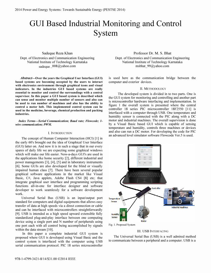
The developed system is divided in to two parts. One is the GUI system for monitoring and controlling and another part is microcontroller hardware interfacing and implementation. In figure 1 the overall system is presented where the central controller 18 series PIC microcontroller 18F2550 [11] is interfaced with a computer through USB. One temperature and humidity sensor is connected with the PIC along with a DC motor and industrial machines. The overall supervision is done by a Visual Basic based GUI which is capable of sensing temperature and humidity, controls three machines or devices and also can run a DC motor. For developing the code for PIC an advanced level simulator software Flowcode Ver.5 is used.
Fig. 1. Proposed System
III. USB INTERFACING
The Universal Serial Bus (USB) is a well admired method to communicate between a peripheral and a computer. USB is a
sadeque

plug-and-play type interface which can also provide power to the USB devices by only this means that the computer does not plug in or unplug device from the computer. The goal of the USB is to broaden the range of external peripherals that can be used on a computer.
The USB Serial device is used to stream data between the microcontroller system and a Pc. This method of USB is good for transferring both small and large amounts of data in an adhock or as required manner. The Flowcode Serial USB device requires a driver in order to create the virtual COM port connection. This driver file is included as part of the USB pack of Flowcode ver. 5 software with a default device name of "Flowcode USB Serial". The Flowcode USB serial component creates a virtual COM port on the PC which is shown in figure 2, it is connected to which enables easy software access to the device data streams.
Fig. 2.
.. Printers and Faxes (3)
• Unspecified (1)
Flowcode USB
Serial (COM9)
(dRom Device
Microsoft XPS
Document Writer
Every USB device must have a unique set of PID (Product ID) and VID (Vendor ID) codes. For this device the VID is Ox12BF and PID is OxFOIO. Here the USB communication is done with a Standard-B type plug in connector.
IV. GUI DEVELOPMENT
For this project Graphical User Interface (GUI) is developed by using Visual Basic 2010. Visual Basic has a default serial communication prototype. Designer only has to configure that according to required serial device. In figure 3 the designed GUI is shown. The whole GUI panel is divided in to four sections. The fust section is designed to connect the GUI with the USB or disconnect. The Baud rate is fixed to 9600 bps in the code. Here user only has to select the COM port where device is connected. In Sensor Panel temperature and humidity is shown. Here sensor data is received as a string value. For categorizing and recognizing different sensor values an initial identifying character is received for corresponding sensors. Here any number of sensors can be imposed in the
GUI. In Control Panel three on and off switches are given to control three machines or devices. Here also the string value is send to the microcontroller to control a particular pin for switching operation. Here Motor Panel is also implemented to control the forward and reverse rotation and also a stop button is there to stop the motor instantly and speed control slide bar is also included. Flow chart for the GUI is given in figure 4.
rl� Con trol Pa nel
USB Panel
Com Port:
Connect I Disconnect I Sensor Panne!
Temperature: 29 ·c Humidity: 58
Control Panel
SW10N I SW20N I SW30N
SW10FF I SW20FF I SW30FF
Motor
I Forwam Reverse I Stop
o Speed Control
Fig. 3. Proposed GUT
CODDect? >Y"------c ____ ---,
N
Fig. 4. GUI Flow Chart
N Send String to uC of Particular
en th to Set On a Low 110 Pi
,---,-N'--<.DiscODoect?
Y
This kind of GUI can be used in chemical and medicine production industries where the environment monitoring is a major concern. Other than that, this GUI can be used for industries like textile, machineries etc.
V. CONTROLLER AND PERIPHERALS DESIGN
As a central controller PIC 18F2550 is used in this project. It is a 8-bit 28-pin microcontroller with a 10-bit ADC and with USB interfacing module. Here USB interfacing is done by a type B connector. For temperature sensing DS18B20 is used in this project. DSI8B20 is a single-bus intelligent temperature sensor which can generate serial output, the temperature range of -55 � 125°C (in the range of -10 � 85°C with the accuracy of ± O.5°C) [12]. DS18B20 can be used in parasite power mode where the communication with master and power taking both are done via the I-Wire bus [13]. One wire communication can be established with any 110 or analog pin of microcontroller. For humidity measurement HDK series humidity sensor is used. It is a linear humidity sensor. We can control different high power machines or devices through the microcontroller output by using relay and a opto-coupler in between the relay and microcontroller. Opto-coupler is used to isolate the microcontroller optically for its safety from any kind of disaster. For motor speed controlling Pulse Width Modulation (PWM) module of microcontroller is used. PIC 18F2550 has two built in PWM channels. So both the channels are used for speed controlling and direction controlling along with a motor driver IC L293D. High power motors also can be driven by using MOSFET driver circuits.
VI. RESULT AND DISCUSSION
Flowcode is a high level programming language dedicated to simplifying complex functionality with advanced level simulation environment. Figure 5 shows the simulation window for this project. Here USB serial communication module, I-wire communication module, one knob for ADC, two PWM channels and for output representation five LEDs are added in the simulation panel.
'B4.EROR , B3-0N 'B2-SW3
[disabled]
'B1-SW2 � r; ;,
, A1 1 � I �==:;:::==== BO-SW1 L.; :oJ I PWM1
Fig. 5. Simulation Panel
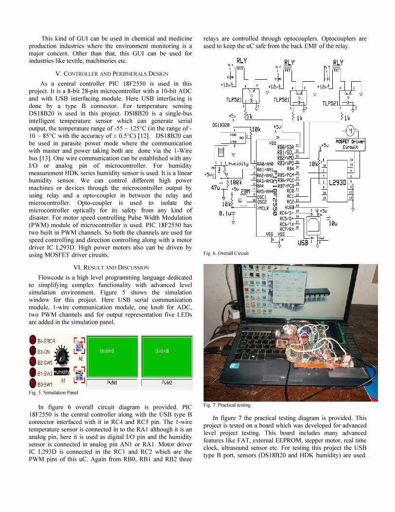
In figure 6 overall circuit diagram is provided. PIC 18F2550 is the central controller along with the USB type B connector interfaced with it in RC4 and RC5 pin. The I-wire temperature sensor is connected in to the RA 1 although it is an analog pin, here it is used as digital 110 pin and the humidity sensor is connected in analog pin ANI or RAl. Motor driver IC L293D is connected in the RC 1 and RC2 which are the PWM pins of this uc. Again from RBO, RB 1 and RB2 three
relays are controlled through optocouplers. Optocouplers are used to keep the uC safe from the back EMF of the relay.
+12v
YDD RB0/SDA 21 RBltSCL 22 RB2/YMO 23
2 RA0/AN0 RB3/YPO 24 3 RAlIANI RB425 4 RA2/AN2� RB5/PGM 26 5 RA3/AN3(l RB6/PGC 27 6 RA4 .... RB7/PGD 28 7 RA5/AN4CXl RC0 II
9 ascI il RCI 11
+12v
+5v
10k 16 2
10 IS 10 aSC2 ru RC2 13 10klt-__ -'-11 IMCLR � YUSBf-"14'----,-,----, 0. 1 uJ (S) RC4/D- IS
Fig. 6. Overall Circuit
Fig. 7. Practical testing
RC5/D+ 16
RC6/TX 17 RC7/RX 18
YSS
14 II
L293D 4 5 11
13
In figure 7 the practical testing diagram is provided. This project is tested on a board which was developed for advanced level project testing. This board includes many advanced features like FAT, external EEPROM, stepper motor, real time clock, ultrasound sensor etc. For testing this project the USB type B port, sensors (DS18B20 and HDK humidity) are used.

The L293D connected motor is also available in the board, so that section is also tested from that board. The relay section is tested through the LED section of the board.
VII. CONCLUSION
The system is designed for high preCISlOn industrial works. The controller uses USB communication for PC based control over the speed of the motor and also monitoring for different sensing parameters. The developed system can be used in different industrial machines and also any number of machines can be maintained. Visual Basic based GUI provides the opportunity to build the installation file and to use in any Pc. The plug and play makes the USB to interface and use easy. The overall system is low cost and beneficial for any industry use.
REFERENCES
[1] Jorgensen, A. H. and Myers, B. A. "User interface history".
Proceeding CHi '08 extended abstracts on Human factors in
computing systems, 2008, pp. 2415-2418.
[2] Harnani Hassan, Raudah Abu Bakar, Ahmad Thaqib Fawwaz
Mokhtar, "Face Recognition Based on Auto-Switching Magnetic
Door Lock System Using Microcontroller ", 2012 International
Conference on System Engineering and Technology September
11-12, 2012.
[3] G. Flori, O. N. Hemming, A. Luchetta, G. Manduchi, V.
Schmidt2, C. Talierci03, S. Vitturi, "Graphical User Interface of
RFX Control and Data Acquisition System", 15th IEEEINPSS
Symposium on Fusion Engineering, 1993., (Volume:2 ), pp.
577 - 580.
[4] Marc Lavergne, "Graphical User Interface for Next Generation
Power Systems", Twenty-second International
Telecommunications Energy Conference, 2000. INTELEC, pp.
109 - 112.
[5] Yu-Chen Chen, Yuan-Hsiang Chang, Te-Chuan Wang, "A Real
Time Computer Graphical User Interface for Advanced Boiling
Water Reactor Case Comparison Using MAAP Software",
Computer Symposium (ICS), 2010 International IEEE
conference, pp. 274 - 278.
[6] Scott Koziol, Craig Schlottmann, Arindam Basu, Stephen Brink,
Csaba Petre, Brian Degnan, Shubha Ramakrishnan, Paul Hasler,
and Aurele Balavoine, " Live Demonstration: Hardware and
Software Infrastructure for a family of Floating-Gate Based
FPAAs " Proceedings of 2010 IEEE International Symposium
on Circuits and Systems (ISCAS), pp. 2793.
[7] Frank McKiel Jf. "Audio-Enabled Graphical User Interface For
The Blind Or Visually Impaired", Proceedings of the Johns
Hopkins National Search for Computing Applications to Assist
Persons with Disabilities, 1992, pp. 185 - 187.
[8] Andisheh Feizil, Chui Yin Wong, " Usability of User Interface
Styles for Learning a Graphical Software Application ", 2012
International Conference on Computer & Information Science (ICCIS), pp. 1089-1094.
[9] Gurinder Singh, Lakshmi Munukutla, " Interfacing USB Printer
using Vinculum Host Controller", American Society for
Engineering Education, 2009.
[10] Soumyajit Datta, Sumana Chowdhuri Jitendranath Bera
"Development of USB compatible PC based PD motorcontroller
for chemical process", 2012 1st International Conference on
Power and Energy in NERIST (ICPEN), pp. 1 - 4.
[11] Gonzalez, M.F.O, Arizaga, S.lA. ; Moreno, B.O.,
"Temperature-Meter via USB Base Don PIC 18F2550 for Solar
Energy Concentrator System", International Conference on
Electrical, Communications, and Computers, 2009,
CONIELECOMP 2009.pp. 1 - 7.
[12] Junqin Wang," Design Intelligent Temperature Monitoring
System Based on DSP", 2012 4th International Conference on
Intelligent Human-Machine Systems and Cybernetics, pp. 234-
237.
[13] Zhou Runjing, Xu Hongwei, Ren Guanzhong, "Design of
Temperature Measurement System Consisted of FPGA and
DSI8B20", 2011 International Symposium on Computer
Science and Society, pp. 90-93.