GUAIGUI MULTIPURPOSE PROJECT ROCK SLOPE · PDF fileInternational Symposium on Stability of...
12
The South African Institute of Mining and Metallurgy International Symposium on Stability of Rock Slopes in Open Pit Mining and Civil Engineering Werner Stefanussen Page 471 GUAIGUI MULTIPURPOSE PROJECT ROCK SLOPE STABILITY M.Sc Rock Mechanics Mr Werner Stefanussen, SWECO Grøner AS, Norway Prof. Bjørn Nilsen, Norwegian University of Science and Technology ABSTRACT The construction of the Guaigui Multipurpose Project includes a 74 metre high concrete face rock fill dam, a 350 metre long diversion tunnel and a 350 metre long spillway tunnel. The topography in the project area is very steep, and the rock masses are characterized as soft rocks. The stability of the 80 to 100 metre high dam abutments and the excavation of the tunnels in soft rock conditions have caused various challenges and problems to be solved. Limited pre-investigations have called to a great extent for estimation of parameters for the stability calculations based on experience. The preliminary calculation of the stability of the planned rock slope above the spillway intake platform has been carried out by conventional partial factor methods and by use of a computed based Slide Program. The two methods of calculation give different results , and that rock support is necessary to obtain an acceptable factor of safety for a slope inclination of 52 o . The input parameters for the rock mass characteristics need to be verified for the permanent calculations. 1 INTRODUCTION Guaigui Multipurpose Project is planned to be a multipurpose project for water supply to a nearby city, irrigation for agriculture, flood control and hydropower supply. The project includes a 74 metre high rock fill dam, two tunnels of 350 metre length and a hydropower station generating 2 MW. The project is government-owned and the client is Instituto Nacional de Recursos Hidraulicos (INDRHI). The construction of the project started in 2001, and the first stage was completed in 2003. This includes the excavation of the diversion tunnel, the cleaning and preparation of the dam foundations and construction of the cofferdam. The construction was stopped in June 2003, due to disagreement between the client and the contractor. The consultant engineer was SWECO Grøner AS, and the contractor for the first stage was NCC International. 2 THE DOMINICAN REPUBLIC - PARADISE ON EARTH? The Dominican Republic is located on an island in the Caribbean named Hispanola. The island is located south of Cuba and includes Haiti and The Dominican Republic. The population as about 8.5 million and the area is about 48,500 km 2 . The official language is
Transcript of GUAIGUI MULTIPURPOSE PROJECT ROCK SLOPE · PDF fileInternational Symposium on Stability of...

The South African Institute of Mining and Metallurgy International Symposium on Stability of Rock Slopes in Open Pit Mining and Civil Engineering Werner Stefanussen
Page 471
GUAIGUI MULTIPURPOSE PROJECT ROCK SLOPE STABILITY
M.Sc Rock Mechanics Mr Werner Stefanussen, SWECO Grøner AS, Norway
Prof. Bjørn Nilsen, Norwegian University of Science and Technology
ABSTRACT
The construction of the Guaigui Multipurpose Project includes a 74 metre high concrete face rock fill dam, a 350 metre long diversion tunnel and a 350 metre long spillway tunnel. The topography in the project area is very steep, and the rock masses are characterized as soft rocks. The stability of the 80 to 100 metre high dam abutments and the excavation of the tunnels in soft rock conditions have caused various challenges and problems to be solved. Limited pre-investigations have called to a great extent for estimation of parameters for the stability calculations based on experience. The preliminary calculation of the stability of the planned rock slope above the spillway intake platform has been carried out by conventional partial factor methods and by use of a computed based Slide Program. The two methods of calculation give different results , and that rock support is necessary to obtain an acceptable factor of safety for a slope inclination of 52o. The input parameters for the rock mass characteristics need to be verified for the permanent calculations. 1 INTRODUCTION Guaigui Multipurpose Project is planned to be a multipurpose project for water supply to a nearby city, irrigation for agriculture, flood control and hydropower supply. The project includes a 74 metre high rock fill dam, two tunnels of 350 metre length and a hydropower station generating 2 MW. The project is government-owned and the client is Instituto Nacional de Recursos Hidraulicos (INDRHI). The construction of the project started in 2001, and the first stage was completed in 2003. This includes the excavation of the diversion tunnel, the cleaning and preparation of the dam foundations and construction of the cofferdam. The construction was stopped in June 2003, due to disagreement between the client and the contractor. The consultant engineer was SWECO Grøner AS, and the contractor for the first stage was NCC International. 2 THE DOMINICAN REPUBLIC - PARADISE ON EARTH? The Dominican Republic is located on an island in the Caribbean named Hispanola. The island is located south of Cuba and includes Haiti and The Dominican Republic. The population as about 8.5 million and the area is about 48,500 km2. The official language is
The South African Institute of Mining and Metallurgy International Symposium on Stability of Rock Slopes in Open Pit Mining and Civil Engineering Werner Stefanussen
Page 472
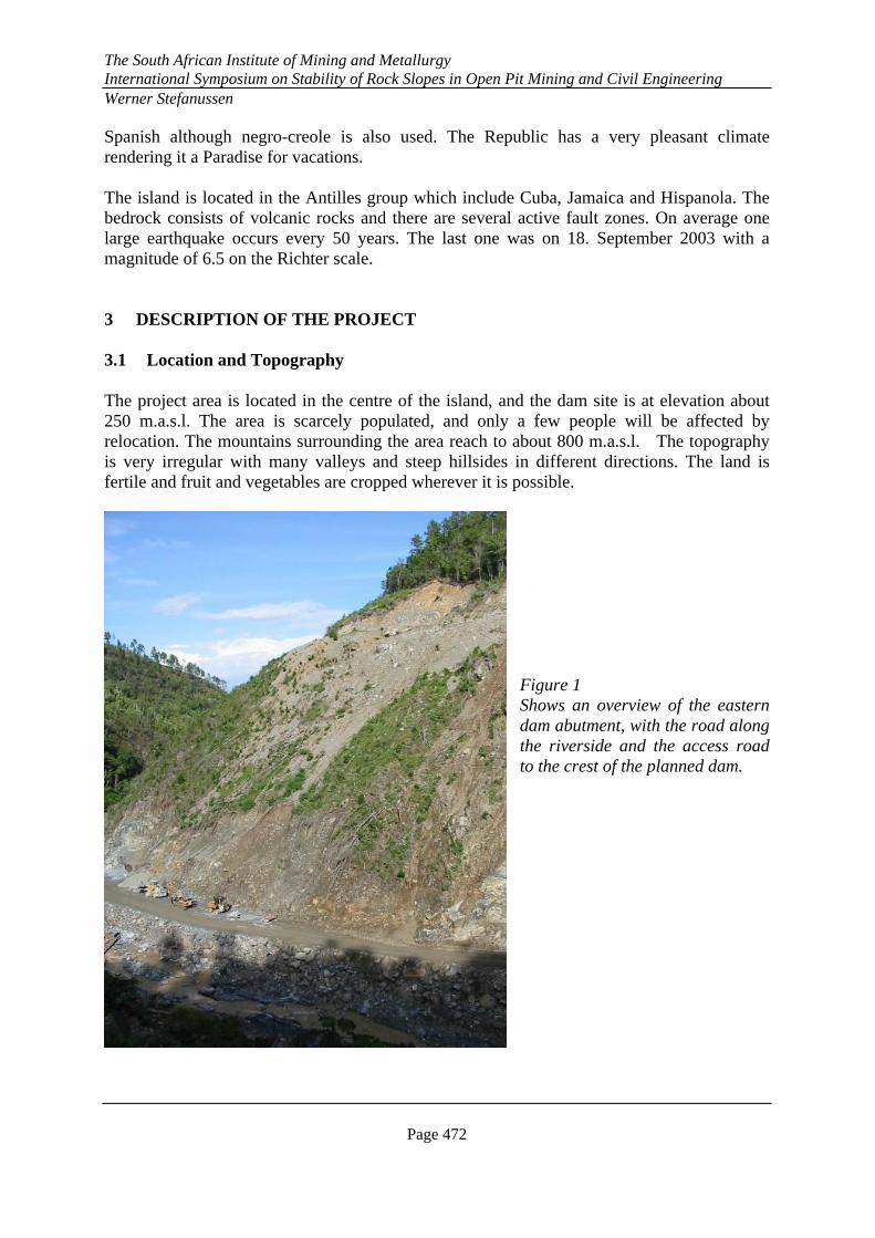
Spanish although negro-creole is also used. The Republic has a very pleasant climate rendering it a Paradise for vacations. The island is located in the Antilles group which include Cuba, Jamaica and Hispanola. The bedrock consists of volcanic rocks and there are several active fault zones. On average one large earthquake occurs every 50 years. The last one was on 18. September 2003 with a magnitude of 6.5 on the Richter scale. 3 DESCRIPTION OF THE PROJECT 3.1 Location and Topography The project area is located in the centre of the island, and the dam site is at elevation about 250 m.a.s.l. The area is scarcely populated, and only a few people will be affected by relocation. The mountains surrounding the area reach to about 800 m.a.s.l. The topography is very irregular with many valleys and steep hillsides in different directions. The land is fertile and fruit and vegetables are cropped wherever it is possible.
Figure 1 Shows an overview of the eastern dam abutment, with the road along the riverside and the access road to the crest of the planned dam.
The South African Institute of Mining and Metallurgy International Symposium on Stability of Rock Slopes in Open Pit Mining and Civil Engineering Werner Stefanussen
Page 473
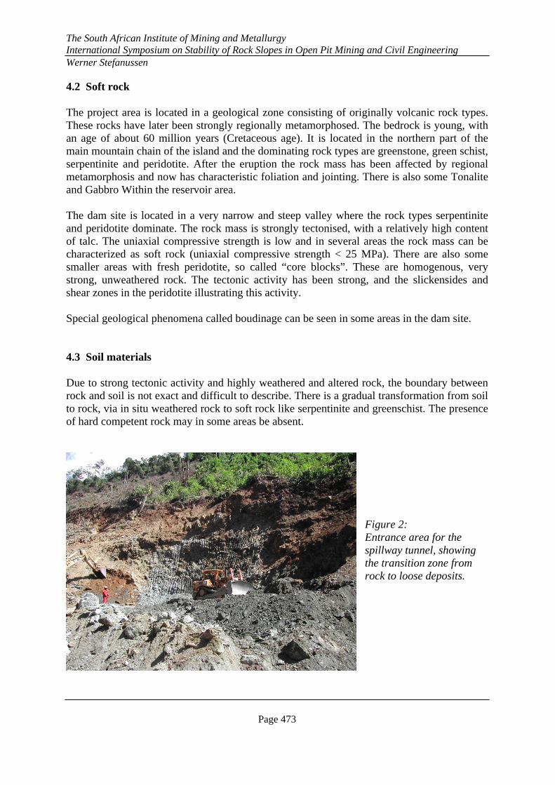
4.2 Soft rock The project area is located in a geological zone consisting of originally volcanic rock types. These rocks have later been strongly regionally metamorphosed. The bedrock is young, with an age of about 60 million years (Cretaceous age). It is located in the northern part of the main mountain chain of the island and the dominating rock types are greenstone, green schist, serpentinite and peridotite. After the eruption the rock mass has been affected by regional metamorphosis and now has characteristic foliation and jointing. There is also some Tonalite and Gabbro Within the reservoir area. The dam site is located in a very narrow and steep valley where the rock types serpentinite and peridotite dominate. The rock mass is strongly tectonised, with a relatively high content of talc. The uniaxial compressive strength is low and in several areas the rock mass can be characterized as soft rock (uniaxial compressive strength < 25 MPa). There are also some smaller areas with fresh peridotite, so called “core blocks”. These are homogenous, very strong, unweathered rock. The tectonic activity has been strong, and the slickensides and shear zones in the peridotite illustrating this activity. Special geological phenomena called boudinage can be seen in some areas in the dam site. 4.3 Soil materials Due to strong tectonic activity and highly weathered and altered rock, the boundary between rock and soil is not exact and difficult to describe. There is a gradual transformation from soil to rock, via in situ weathered rock to soft rock like serpentinite and greenschist. The presence of hard competent rock may in some areas be absent.
Figure 2: Entrance area for the spillway tunnel, showing the transition zone from rock to loose deposits.
The South African Institute of Mining and Metallurgy International Symposium on Stability of Rock Slopes in Open Pit Mining and Civil Engineering Werner Stefanussen
Page 474
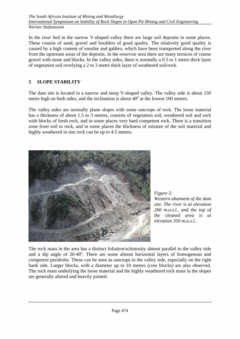
In the river bed in the narrow V-shaped valley there are large soil deposits in some places. These consist of sand, gravel and boulders of good quality. The relatively good quality is caused by a high content of tonalite and gabbro, which have been transported along the river from the upstream areas of the deposits. In the reservoir area there are many terraces of coarse gravel with stone and blocks. In the valley sides, there is normally a 0.5 to 1 metre thick layer of vegetation soil overlying a 2 to 3 metre thick layer of weathered soil/rock. 5 SLOPE STABILITY The dam site is located in a narrow and steep V-shaped valley. The valley side is about 150 metre high on both sides, and the inclination is about 40o at the lowest 100 metres. The valley sides are normally plane slopes with some outcrops of rock. The loose material has a thickness of about 1.5 to 3 metres, consists of vegetation soil, weathered soil and rock with blocks of fresh rock, and in some places very hard competent rock. There is a transition zone from soil to rock, and in some places the thickness of mixture of the soil material and highly weathered in situ rock can be up to 4.5 metres.
Figure 5: Western abutment of the dam site. The river is at elevation 260 m.a.s.l., and the top of the cleaned area is at elevation 350 m.a.s.l..
The rock mass in the area has a distinct foliation/schistosity almost parallel to the valley side and a dip angle of 20-40o. There are some almost horizontal layers of homogenous and competent peridotite. These can be seen as outcrops in the valley side, especially on the right bank side. Larger blocks, with a diameter up to 10 metres (core blocks) are also observed. The rock mass underlying the loose material and the highly weathered rock mass in the slopes are generally altered and heavily jointed.
The South African Institute of Mining and Metallurgy International Symposium on Stability of Rock Slopes in Open Pit Mining and Civil Engineering Werner Stefanussen
Page 475
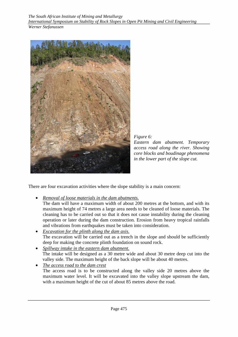
Figure 6: Eastern dam abutment. Temporary access road along the river. Showing core blocks and boudinage phenomena in the lower part of the slope cut.
There are four excavation activities where the slope stability is a main concern:
• Removal of loose materials in the dam abutments. The dam will have a maximum width of about 200 metres at the bottom, and with its maximum height of 74 metres a large area needs to be cleaned of loose materials. The cleaning has to be carried out so that it does not cause instability during the cleaning operation or later during the dam construction. Erosion from heavy tropical rainfalls and vibrations from earthquakes must be taken into consideration.
• Excavation for the plinth along the dam axis. The excavation will be carried out as a trench in the slope and should be sufficiently deep for making the concrete plinth foundation on sound rock.
• Spillway intake in the eastern dam abutment. The intake will be designed as a 30 metre wide and about 30 metre deep cut into the valley side. The maximum height of the back slope will be about 40 metres.
• The access road to the dam crest The access road is to be constructed along the valley side 20 metres above the maximum water level. It will be excavated into the valley slope upstream the dam, with a maximum height of the cut of about 85 metres above the road.
The South African Institute of Mining and Metallurgy International Symposium on Stability of Rock Slopes in Open Pit Mining and Civil Engineering Werner Stefanussen
Page 476
For a complex geology and rock mass of varying quality like here, it is normally very difficult to define the exact parameters for calculating the slope stability. In this article the main focus will be on the rock slopes at the spillway intake, which is regarded as the most critical structure for the operation of the project. 5.1 Spillway intake The intake is to be located about 30 metres above the river level, and the platform to be excavated is to be about 30x30 metres. The natural slope angle is about 41o. Rock blasting will be necessary to establish the platform. To reduce the cost of the blasting, it is very important to make the cut slope as steep as possible. However, the rock support of the slope must also be kept to a minimum. It was possible to evaluate the rock mass conditions in the existing cut and at slopes for the temporary access road above HRW. The access road is excavated through loose material and in the rock mass, consisting of highly fractured/jointed serpentinite. Some of the joints are covered by chlorite, but clay gauge materials have not been observed. Some core drillings have given valuable information about the depth of the weathered zone, and the quality of the rock mass deeper in the slope. From the observations available, there is no indication of any distinct joint plane or fault plane which could cause sliding in the slope. Our calculations are therefore based on the anticipation of a failure through the extensively fractured rock mass. 5.2 Earthquake Factor Earthquake activity has to be included in the calculations for the Guaigui project. In the basic design for the dam a”ground peak acceleration” (GPA) with 500 years return period of 0.29g has been defined. For operational conditions the client has defined the earthquake coefficient to be 0.5xGPA, resulting in 0.15g. The maximum credible earthquake factor (return period 5000 years) is defined as 0.61g. 6 STABILITY CALCULATIONS Stability calculations have been carried out based on traditional methods and based on the partial factor methods. For both methods the concept of active friction angle (basic friction angle plus the cohesion of the material) has been used. Additionally, computer modeling based on the Rocscience Slide Program by using the Barton-Bandis material properties has been done. The analyses were made using the Bishop analysis method. Due to the heavy jointing of the rock mass, the formulas from Hoek & Bray (1981) for shear strength of heavily fractured and highly weathered rock mass, have been used. The shear strength is a function of the normal stress on the failure plane to be tested and will therefore vary with the normal stress situation depending on the thickness of the rock overburden. The
The South African Institute of Mining and Metallurgy International Symposium on Stability of Rock Slopes in Open Pit Mining and Civil Engineering Werner Stefanussen
Page 477
other parameter to be defined is the uniaxial compressive strength of the in situ rock. This means that the jointing and weakness planes in the rock mass are not to be taken into considerations. To calculate the shear strength an average uniaxial compressive strength of 20 MPa has been used, believed to be conservative. The active friction angle is calculated from the shear strength and the normal stress. 6.1 Partial factor-method The partial factors used are defined from Eurocode 7 (CEN 1994) and Norwegian Standards: The following factors have been used: Permanent load (weight of unstable mass): fw=1.0 Variable load (external load like weight from crane): fe=1.3 Ground conditions: tan φ ffi=1.2 Uniaxial compressive strength of rock fc=1.4 The criterion for safety according to the partial factor method is that the stabilizing forces should be greater than the driving forces, i.e Md>Fd, or Md/Fd>1.0 6.1.1 Spillway Intake slope For calculating the stability of the slope the given factors above, with UCS = 20 MPa and Earth Quake Factor = 0.15g have been used. A hydrostatic water pressure corresponding to 9 metres in open, vertical joints at the top level of the slope is included. The calculations were carried out using the formulae from Hoek & Bray (1981) for heavily jointed rock masses, based on the partial factor method. The analysis was carried out by anticipating an overall slope inclination of 52o in the lower part and 43o in the upper part, (which was the result from the traditional calculations), and can be seen in figure No 7. The active friction angle required for giving a Md/Fd-factor >1.0 is found to be 49o. The design of the slope has been proposed to have 10 metre high benches and 3 metre wide berms. The slope angle for the 10 metre high benches in the lower part will be 55o. To take care of the local stability of the berms, rock support with 10 cm thick steel fibre reinforced shotcrete and rock bolts in a pattern of 2x2 metres have been included. Drainage holes are to be drilled in a given pattern. The results concerning the slope inclination (52o and 43o) and the active friction angle (49o) are regarded as reasonable. The earthquake factor has a great influence on the stability of the slope. In table 1 the results from a sensitivity analysis of the lower part of the slope are given. Earthquake coefficient 0.15g 0.17g 0.20g 0.22g Maximum Slope angle 52o 50o 47o 45o Table 1: Effect on the slope from the EQF.
The South African Institute of Mining and Metallurgy International Symposium on Stability of Rock Slopes in Open Pit Mining and Civil Engineering Werner Stefanussen
Page 478
6.2 Computer based calculations by Rocscience Slide Program To have an alternative approach to analysis, and to be more able to evaluate the parameters for the calculations, computer analysis based on Rocscience Slide program has also been carried out. Two methods for calculating the material properties formulae have been evaluated. These are the Barton-Bandis and the Mohr-Coloumb methods. The Barton-Bandis method is found to be more relevant for this purpose because the shear strength curve will be non-linear. Another reason is that the cohesion to be given in the Mohr-Coulomb equation is very difficult to estimate for the rock mass, and it will strongly influence the depth of the failure circle in the rock mass. The Barton-Bandis criteria is as follows: τ = σn tan (φr + JRC log10 (JCS/ σn)) where: JRC = joint roughness coefficient JCS = joint wall compressive strength of the intact rock mass φr = residual friction angle The values of the parameters used in the analysis are:
JRC (joint roughness coefficient): 8.5 JCS (joint wall compressive strength of the intact rock mass): 25 MPa φr (residual friction angle): 38o
An earthquake factor = 0.15g has been included in the calculations, and the ground water table has been defined to be close to the terrain surface. Calculations for the slope above the intake platform and up to the top of the valley side (slope height = 80 m) have been carried out. This includes the slope above the access road. For the slope above the intake platform (from the platform to the access road) the rock support of the slope by installation of rock anchors and shotcrete has been included. The anchors in the lower part of the slope are defined to be 20 metres long with a capacity of 500 kN each, and the anchors in the upper part of the slope are defined to be 10 metres long with a capacity of 200 kN each. For the slope above the access road no rock support has been included. It is, however, evident that local rock support will be necessary to take care of minor instabilities here.
The South African Institute of Mining and Metallurgy International Symposium on Stability of Rock Slopes in Open Pit Mining and Civil Engineering Werner Stefanussen
Page 479
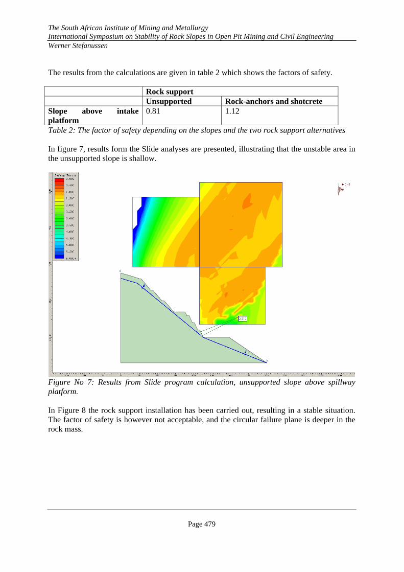
The results from the calculations are given in table 2 which shows the factors of safety. Rock support Unsupported Rock-anchors and shotcrete Slope above intake platform
0.81 1.12
Table 2: The factor of safety depending on the slopes and the two rock support alternatives In figure 7, results form the Slide analyses are presented, illustrating that the unstable area in the unsupported slope is shallow.
Figure No 7: Results from Slide program calculation, unsupported slope above spillway platform. In Figure 8 the rock support installation has been carried out, resulting in a stable situation. The factor of safety is however not acceptable, and the circular failure plane is deeper in the rock mass.

The South African Institute of Mining and Metallurgy International Symposium on Stability of Rock Slopes in Open Pit Mining and Civil Engineering Werner Stefanussen
Page 480
Figure 8: Results from Slide Program calculations, rock supported slope above spillway platform. 7 CONCLUSION The investigations and the calculations of the stability situation and the excavation design of the slopes have given the following conclusions:
1) The Partial Factor Method gives an acceptable stability factor (Md/Fd>1.0) for a maximum slope inclination of 52o in the supported rock slope above the spillway intake. The necessary active friction angle to give a stability factor > 1.0 with a slope inclination of 52 o and 43o for the lower and upper part is found to be 49o, which is regarded as relevant for the situation
2) Slide Computer Analysis and the Barton-Bandis approach give a Factor of Safety
of1.12 for the overall stability of the supported rock slope above the spillway intake. The values of the parameters used in the calculations ( φr = 38o, JCS = 25 MPa and JRC = 8.5) are not verified and must be taken as preliminary numbers.
3) The two alternative methods used in this analyses (Partial factor method and Slide
Computer Program) give slightly different results, but a reasonable preliminary basis for evaluating the slope stability. The input parameters for the rock mass characteristic have to be verified, and/or the slope inclinations possibly have to be adjusted depending on the results of this verification. Installation of more heavy rock support (large rock anchors) may be needed.
The South African Institute of Mining and Metallurgy International Symposium on Stability of Rock Slopes in Open Pit Mining and Civil Engineering Werner Stefanussen
Page 481
8 STATUS AS PER DECEMBER 2005 As per December 2005 the diversion tunnel had been completed and the cofferdam constructed. The spillway tunnel was halfway excavated and the cleaning of the dam abutment on the left side was completed. The cleaning and excavation for the dam abutment, the spillway intake and the permanent access road on the right side were not started. The construction has been halted from June 2003 until now because the contractor has been released from the contract, and a new contractor is to restart the construction. SWECO Grøner AS has been awarded the contract for detailed design of the dam, the tunnels and the hydropower plant. The design is to start in January 2006. The restart of the construction is anticipated to take place in the second quarter of 2006. REFERENCES Hoek, E & Bray. Rock Slope Engineering. Revised Third EditionThe Institution of Mining and Metallurgy, London 1981. Nilsen, B. New Trends in rock slope stability analyses. Bull Eng Geol Env (2000) 58: 173-178. NBG. Engineering geology and rock engineering. Norwegian Nat. Group of ISRM (NBG). Handbook no 2, 2000 ROCSCIENCE: Slide Manual, 2005

The South African Institute of Mining and Metallurgy International Symposium on Stability of Rock Slopes in Open Pit Mining and Civil Engineering Werner Stefanussen
Page 482