Gtx 327 Supplement
8
Garmin GTX 327 Series Equipment Supplement Revision A 15-Dec-2012
description
aviation
Transcript of Gtx 327 Supplement

Garmin GTX 327 Series
Equipment Supplement
Revision A
15-Dec-2012

Garmin GTX 327 Series Supplement GRT Avionics
Revision A GTX 327-2
Section 1: Introduction
1.1 About the GTX 327………..….………………………….………………………………………………………….. 3
1.2 Data Port and Hardware Requirements…………………………………………………………………… 3
Section 2: Installation & Wiring
2.1 Suggested Connections…………………………………………………………………………………………… 4
2.2 Worksheet: My System…………………………………………………………………………………………….. 4
Section 3: Setup & Programming
3.1 Display Unit Setup……………………………………………………………………………………………………. 5
3.2 Configuring The GTX 327………………………………………………………………………………………… 6
3.3 Post-Installation Check-Out…………………………………………………………………………………….. 6
Section 4: Pilot’s Guide Supplement
4.1 Using the GTX 327…………………………………………………………………………………………………. 7
Table of Contents
Revision A GTX 327-3
GRT Avionics Garmin GTX 327 Series Supplement
Section 1: Introduction
1.1 About the GTX 327 TransponderThe Garmin GTX 327 Mode C transponder series provides altitude and radar identity data to ATC.This transponder can use either Grey code or RS-232 serial data to receive fuel/air data from theEFIS, which contains a built-in altitude encoder. This supplement provides suggested methods forconnecting the GPS to the EFIS display unit to allow optimal performance of both units. (NOTE:HXr does not support Grey code.)
Download the current installation manual appropriate for your transponder from the Garminwebsite and follow all instructions thoroughly. GRT provides pin assignments here for convenience.While the chance that pin assignments will change is very slim, Garmin may change them at anytime.
The interface between this unit and the EFIS allows for:
� Pressure altitude and flight ID to be transmitted to ATC ground stations
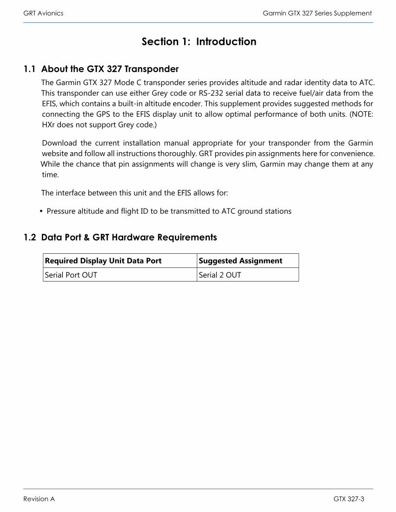
1.2 Data Port & GRT Hardware Requirements
Required Display Unit Data Port Suggested Assignment
Serial Port OUT Serial 2 OUT

Garmin GTX 327 Series Supplement GRT Avionics
Revision A GTX 327-4
Section 2: Installation & Wiring
2.1 Suggested ConnectionsFor more information on Display Unit pins and connectors, see Connector Definitions (HX, SX) onthe GRT website or Pinout Diagrams in HXr Installation Manual.
2.2 Worksheet: My SystemYou may use this form to make a record of your own Serial Port IN and OUT choices.
Horizon HX and HXr EFIS
DisplayUnit Pin
Display UnitFunction GTX 327 Pin GTX 327 Function
B22 Serial 7 OUT P3301-19 (Serial 1 IN)* Fuel air data input for encoder andflight information
* Either GTX 327 serial input may be used.
DisplayUnit Pin Display Unit Port GTX 327 Pin GTX 327 Port Wire Color
Serial ______ OUT P3301- _______ Serial ______ IN
Sport EFIS
DisplayUnit Pin
Display UnitFunction GTX 327 Pin GTX 327 Function
Sport Pin 31 Serial 2 OUT P3301-19 (Serial 1 IN)* Fuel air data in for encoder and flightinformation
* Either GTX 327 serial input may be used.

Revision A GTX 327-5
GRT Avionics Garmin GTX 327 Series Supplement
Section 3: Setup & Programming
3.1 Display Unit SetupAfter the display unit and the GTX 327 unit are installed and wired, use the following table toprogram the display unit to communicate with the GTX 327.
Access the specified Set Menu page in the display unit. Then, look down the list to find each Setting.Press the right knob to activate the setting, and turn the knob to set each corresponding Value.This Setup information applies to all GRT EFIS Systems.
Set Menu Page Setting Value
General Setup Serial Port _____ Rate* 9600
General Setup Serial Port _____ Output* Fuel/Air Data(Z format)
* Fill in blank with display unit serial port you designated for the GTX 327.

Garmin GTX 327 Series Supplement GRT Avionics
Revision A GTX 327-6
3.2 Configuring the GTX 327Refer to the most current Garmin GTX 327 installation manual for instructions for accessing thetransponder Configuration page and setting up other important transponder characteristics. Thisconfiguration information only applies to the settings that affect the transponder’s communicationwith the EFIS system; there may be other settings required to make the transponder functionproperly.
3.3 Post-Installation Checkout for the GTX 3271. Check that the GTX 327 has a pressure altitude showing on the display.
2. With the GTX 327 turned on go to the Set Menu, General Setup. Check the designatedserial ports counter is active and counting.
RS-232 INPUT/OUTPUT page INPUT OUTPUT
CHNL 1* FADC W/ALT OFF
* GTX 327 Serial Input wired to Display Unit

Garmin GTX 327 Series Supplement GRT Avionics
Revision A GTX 327-7
Section 4: Pilot’s Guide
4.1 Using the GTX 327There are no special procedures necessary for using the GTX 327 transponder in flight with a GRTEFIS system. Please refer to the Garmin pilot’s guide for instructions on transponder operation.

Garmin GTX 327 Series Supplement GRT Avionics
Revision A GTX 327-8
THIS PAGE INTENTIONALLY BLANK