Quality Management Training Quality circles Bench Mark Kaizen.
Upload
tsolanki2001Category
view
1.106download
20description
1
NIO/TR - 4 /2007
A METHOD OF TRANSFERRING G.T.S. BENCHMARK VALUE TO SURVEY AREA USING ELECTRONIC TOTAL STATION
GANESAN, P.
DECEMBER 2007
NATIONAL INSTITUTE OF OCEANOGRAPHY REGIONAL CENTRE, VISAKHAPATNAM. INDIA
2
TABLE OF CONTENTS ABSTRACT INTRODUCTION EQUIPMENT USED METHOD OF SURVEY PERMISSIBLE ERROR LIMITS PRECAUTIONS TAKEN RESULTS AND CONCLUSION ACKNOWLEDGEMENT REFERENCES LIST OF TABLES AND FIGURES

3
A METHOD OF TRANSFERRING G.T.S. BENCHMARK VALUE TO SURVEY AREA USING ELECTRONIC TOTAL STATION
GANESAN, P.
( National Inst. Of Oceanography, Regional Centre, Visakhapatnam. )
(Email: [email protected] Phone:0891-2539180) (Keywords: G.T.S. Benchmark, Mean sea level, Chart datum. Tide pole, Inter-tidal zone)
ABSTRACT
A G.T.S. (Great Trigonometrical Survey) benchmark is a permanently fixed
reference survey station (or point), having known elevation with respect to a standard
datum (mean sea level). These are established all over India by Survey of India
department with greater precision. A benchmark value is quite essential at any survey
area, especially for reduction of observed sea level with respect to mean sea level or
chart datum (CD). While carrying out bathymetric survey of a survey area, the datum
referenced values thus obtained are used to compute the final depth contours of the
survey area (with respect to CD). So, a benchmark, having known elevation is quite
essential at the survey area, without which, preparation of a bathymetric chart is
impossible. In some places, GTS benchmarks are available within a kilometer distance
and can be easily transferred to the survey area by fly leveling using an automatic Level
instrument and a graduated leveling staff. But in most of the cases, GTS benchmarks
may be at far away distance from the area to be surveyed. In these cases, the most
common traditional method of transferring the benchmark value using an automatic level
instrument is a difficult task, consuming enormous amount of time and labour. To
eliminate this process, a method is suggested in this technical report to transfer GTS
benchmark from any far distance to the survey area. A latest Electronic Total Station
(ETS) is the instrument that can be used for this purpose. The main advantage in
applying this method is that considerable amount of time can be saved while maintaining
the required accuracy.

4
INTRODUCTION A benchmark (B.M.) is defined as a fixed reference point of known elevation with
respect to a standard datum. A datum (or plane) is any arbitrarily assumed surface level
(or line) from which vertical distances are measured. G.T.S. benchmarks are the ones,
which are established at spacial intervals all over the country, with very high precision by
Survey of India (SOI) department. Their geographical position and elevation above the
standard datum (mean sea level) are given in catalogues, as well as, on G.T.S. maps,
published by SOI. While carrying out bathymetric surveys or observation of tides, these
benchmarks are very much essential to refer the readings with respect to mean sea level
or chart datum. If these G.T.S. benchmarks are available near the survey area, they can
be easily used for this purpose. However, if these benchmarks are located beyond 5
kilometers away from the survey area, transferring this level to the survey area becomes
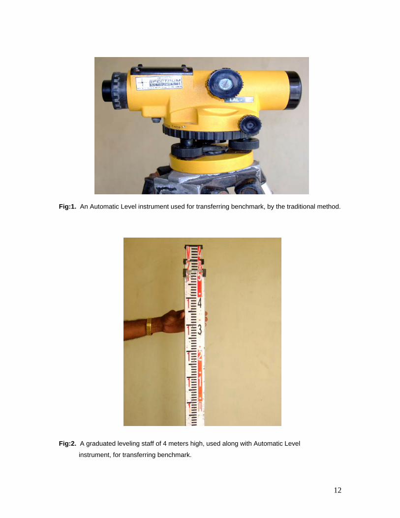
very tedious, especially using a combination of an automatic level instrument (Fig: 1)
and a graduated leveling staff (Fig: 2), which has been the traditional method so far.
The traditional method being very tedious and time consuming, a better method is being
suggested in this report.
ELECTRONIC TOTAL STATION In the improved method, to obtain the geographical positions of baseline
points “A” and “B”, (Fig: 1), “Ceeducer” differential global positioning system (Fig: 4) can
be used. This instrument computes geographical position of any point using the raw data
collected from four satellites in the horizon. Also, it receives transit time error corrections
from nearby land based marine beacons. After applying these corrections, the final
position is obtained which has an accuracy within a meter. These positions can be
entered in electronic total station to get the azimuth of the baseline “AB”. Electronic
Total Station of “TOPCON” make and “GPT-3002N” model can be used for obtaining
geographical co-ordinates and elevation of every point sighted with respect to G.T.S.
benchmark “A”. Electronic Total Station uses both an invisible Pulse Laser Diode for
distance measurement and a visible Red Laser Beam as a laser pointer to identify the
measurement point at the center of the cross hair lines of the telescope. The instrument
has a keyboard containing 24 keys, which makes it easier and quicker to key in codes
and other alphanumeric characters. The output contains several displays based on
5
user’s choice. The output contains measured field data display listing horizontal angle,
vertical angle and laser measured slant distance, computed co-ordinate data display
listing geographical location of the point surveyed (Easting, Northing) and elevation of
the surveyed point with respect to the instrument station elevation and so on. A dual axis
compensator sensor is included in this model, which automatically corrects the
horizontal and vertical angle compensation for leveling error, thereby ensuring accurate
and reliable reading.
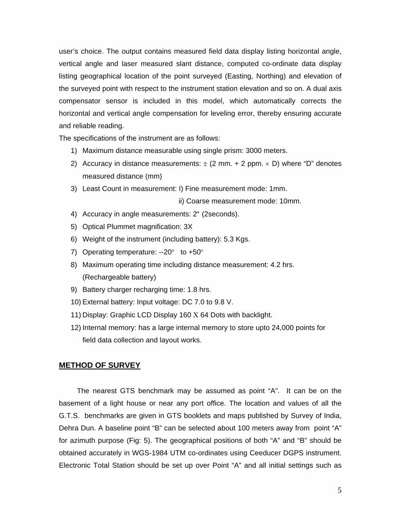
The specifications of the instrument are as follows:
1) Maximum distance measurable using single prism: 3000 meters.
2) Accuracy in distance measurements: ± (2 mm. + 2 ppm. × D) where “D” denotes
measured distance (mm)
3) Least Count in measurement: I) Fine measurement mode: 1mm.
ii) Coarse measurement mode: 10mm.
4) Accuracy in angle measurements: 2″ (2seconds).
5) Optical Plummet magnification: 3X
6) Weight of the instrument (including battery): 5.3 Kgs.
7) Operating temperature: --20° to +50°
8) Maximum operating time including distance measurement: 4.2 hrs.
(Rechargeable battery)
9) Battery charger recharging time: 1.8 hrs.
10) External battery: Input voltage: DC 7.0 to 9.8 V.
11) Display: Graphic LCD Display 160 Χ 64 Dots with backlight.
12) Internal memory: has a large internal memory to store upto 24,000 points for
field data collection and layout works.
METHOD OF SURVEY
The nearest GTS benchmark may be assumed as point “A”. It can be on the
basement of a light house or near any port office. The location and values of all the
G.T.S. benchmarks are given in GTS booklets and maps published by Survey of India,
Dehra Dun. A baseline point “B” can be selected about 100 meters away from point “A”
for azimuth purpose (Fig: 5). The geographical positions of both “A” and “B” should be
obtained accurately in WGS-1984 UTM co-ordinates using Ceeducer DGPS instrument.
Electronic Total Station should be set up over Point “A” and all initial settings such as
6
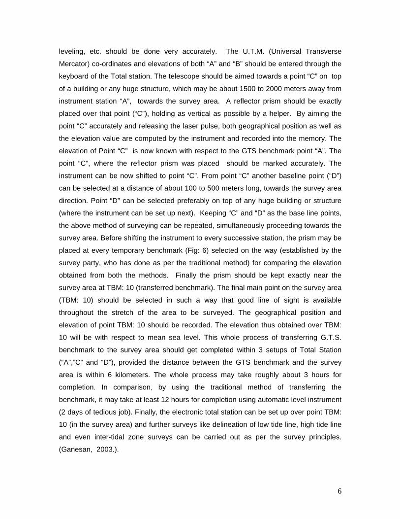
leveling, etc. should be done very accurately. The U.T.M. (Universal Transverse
Mercator) co-ordinates and elevations of both “A” and “B” should be entered through the
keyboard of the Total station. The telescope should be aimed towards a point “C” on top
of a building or any huge structure, which may be about 1500 to 2000 meters away from
instrument station “A”, towards the survey area. A reflector prism should be exactly
placed over that point (“C”), holding as vertical as possible by a helper. By aiming the
point “C” accurately and releasing the laser pulse, both geographical position as well as
the elevation value are computed by the instrument and recorded into the memory. The
elevation of Point “C” is now known with respect to the GTS benchmark point “A”. The
point “C”, where the reflector prism was placed should be marked accurately. The
instrument can be now shifted to point “C”. From point “C” another baseline point (“D”)
can be selected at a distance of about 100 to 500 meters long, towards the survey area
direction. Point “D” can be selected preferably on top of any huge building or structure
(where the instrument can be set up next). Keeping “C” and “D” as the base line points,
the above method of surveying can be repeated, simultaneously proceeding towards the
survey area. Before shifting the instrument to every successive station, the prism may be
placed at every temporary benchmark (Fig: 6) selected on the way (established by the
survey party, who has done as per the traditional method) for comparing the elevation
obtained from both the methods. Finally the prism should be kept exactly near the
survey area at TBM: 10 (transferred benchmark). The final main point on the survey area
(TBM: 10) should be selected in such a way that good line of sight is available
throughout the stretch of the area to be surveyed. The geographical position and
elevation of point TBM: 10 should be recorded. The elevation thus obtained over TBM:
10 will be with respect to mean sea level. This whole process of transferring G.T.S.
benchmark to the survey area should get completed within 3 setups of Total Station
(“A”,”C” and “D”), provided the distance between the GTS benchmark and the survey
area is within 6 kilometers. The whole process may take roughly about 3 hours for
completion. In comparison, by using the traditional method of transferring the
benchmark, it may take at least 12 hours for completion using automatic level instrument
(2 days of tedious job). Finally, the electronic total station can be set up over point TBM:
10 (in the survey area) and further surveys like delineation of low tide line, high tide line
and even inter-tidal zone surveys can be carried out as per the survey principles.
(Ganesan, 2003.).
7
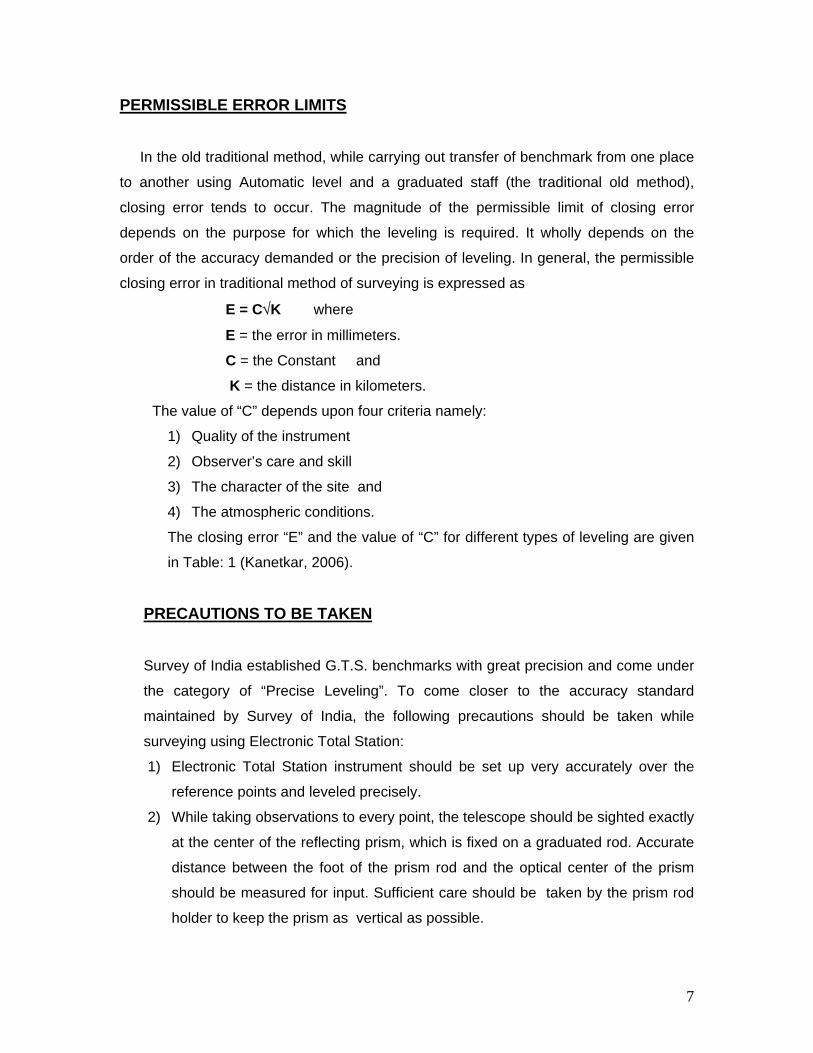
PERMISSIBLE ERROR LIMITS
In the old traditional method, while carrying out transfer of benchmark from one place
to another using Automatic level and a graduated staff (the traditional old method),
closing error tends to occur. The magnitude of the permissible limit of closing error
depends on the purpose for which the leveling is required. It wholly depends on the
order of the accuracy demanded or the precision of leveling. In general, the permissible
closing error in traditional method of surveying is expressed as
E = C√K where
E = the error in millimeters.
C = the Constant and
K = the distance in kilometers.
The value of “C” depends upon four criteria namely:
1) Quality of the instrument
2) Observer’s care and skill
3) The character of the site and
4) The atmospheric conditions.
The closing error “E” and the value of “C” for different types of leveling are given
in Table: 1 (Kanetkar, 2006).
PRECAUTIONS TO BE TAKEN
Survey of India established G.T.S. benchmarks with great precision and come under
the category of “Precise Leveling”. To come closer to the accuracy standard
maintained by Survey of India, the following precautions should be taken while
surveying using Electronic Total Station:
1) Electronic Total Station instrument should be set up very accurately over the
reference points and leveled precisely.
2) While taking observations to every point, the telescope should be sighted exactly
at the center of the reflecting prism, which is fixed on a graduated rod. Accurate
distance between the foot of the prism rod and the optical center of the prism
should be measured for input. Sufficient care should be taken by the prism rod
holder to keep the prism as vertical as possible.
8
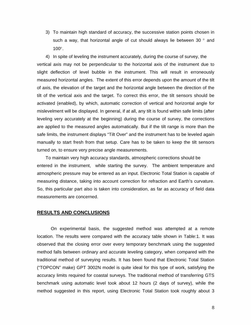
3) To maintain high standard of accuracy, the successive station points chosen in
such a way, that horizontal angle of cut should always lie between 30 ° and
100°.
4) In spite of leveling the instrument accurately, during the course of survey, the
vertical axis may not be perpendicular to the horizontal axis of the instrument due to
slight deflection of level bubble in the instrument. This will result in erroneously
measured horizontal angles. The extent of this error depends upon the amount of the tilt
of axis, the elevation of the target and the horizontal angle between the direction of the
tilt of the vertical axis and the target. To correct this error, the tilt sensors should be
activated (enabled), by which, automatic correction of vertical and horizontal angle for
mislevelment will be displayed. In general, if at all, any tilt is found within safe limits (after
leveling very accurately at the beginning) during the course of survey, the corrections
are applied to the measured angles automatically. But if the tilt range is more than the
safe limits, the instrument displays “Tilt Over” and the instrument has to be leveled again
manually to start fresh from that setup. Care has to be taken to keep the tilt sensors
turned on, to ensure very precise angle measurements.
To maintain very high accuracy standards, atmospheric corrections should be
entered in the instrument, while starting the survey. The ambient temperature and
atmospheric pressure may be entered as an input. Electronic Total Station is capable of
measuring distance, taking into account correction for refraction and Earth’s curvature.
So, this particular part also is taken into consideration, as far as accuracy of field data
measurements are concerned.
RESULTS AND CONCLUSIONS On experimental basis, the suggested method was attempted at a remote
location. The results were compared with the accuracy table shown in Table:1. It was
observed that the closing error over every temporary benchmark using the suggested
method falls between ordinary and accurate leveling category, when compared with the
traditional method of surveying results. It has been found that Electronic Total Station
(“TOPCON” make) GPT 3002N model is quite ideal for this type of work, satisfying the
accuracy limits required for coastal surveys. The traditional method of transferring GTS
benchmark using automatic level took about 12 hours (2 days of survey), while the
method suggested in this report, using Electronic Total Station took roughly about 3
9
hours. In the proposed method, a hired vehicle should be used for shifting the instrument
and to move between successive survey points.
The suggested method is quite useful for setting up and transferring the mean
sea level (or Chart Datum) on tide poles (for tidal observations) wherever it needs to be
installed. As it is quite easier to transfer known mean sea level elevation from anywhere
to the survey area, bathymetric surveys along inter-tidal zones at remote areas can be
performed with great ease. In this method, the geographical positions of the two base
line points (including the light house point) can be observed using Ceeducer DGPS
instrument. As Electronic Total Station is a land based survey instrument requiring only
two known geographical locations and one elevation above mean sea level, the same
instrument can be used for delineating high tide line, low tide line and inter-tidal zone
surveys (Fig:7). As hiring of boat is not essential for performing this job, the expenditure
can be reduced to bare minimum. If ultimate care is taken at every setup, while handling
and operating the instrument, better results can be obtained.
The suggested method is very useful and is the first stage of any survey to be carried
out before performing the following land and hydrographic surveys:
i) Bathymetric surveys along inter-tidal zone areas, where boat cannot reach due to less
or no water.
ii) Delineation of Low tide line surveys. Basically, low tide line is the zero meter contour
line of the survey area with respect to chart datum. After transferring the benchmark to
the main point (TBM: 10) on the survey area, low tide line survey can be started
immediately from the same point, by setting up Electronic Total Station over point TBM:
10. As the final output of the survey is based on land based control points, the accuracy
of the final output will be much more stable, when compared to doing the same survey
using a boat. Tidal observations at periodical intervals are useful for several
hydrographic applications. But after observations, all the tidal values have to be reduced
to mean sea level or chart datum. The suggested method is very useful for fixing mean
sea level as well as chart datum over installed tide poles, at any remote locations.
iii) As the instrument displays and records into the internal memory every surveyed
(target) point’s geographical location and elevation, there is no need to note down the
readings manually, thereby eliminating manual error in copying. But in the old traditional
method of surveying using automatic level instrument, every surveyed point has to be
carefully noted in a register manually and the computations have to be performed
manually to get the final elevations. The closing error after computation of field data

10
(comparing both methods) is given in Table: 2. The value of Chart datum with respect
to mean sea level is given in Indian Tide Tables and in hydrographic charts for most of
the places. If needed, all benchmarks can be reduced with respect to chart datum.
ACKNOWLEDGEMENT
The author is very thankful to Dr.Shetye, Director, National Inst. of Oceanography,
Goa, for his kind permission to publish this Technical report. The author duly
acknowledges the support and encouragement provided by Dr.K.S.R. Murthy, Scientist
in Charge of NIO regional centre, Visakhapatnam. Dr.B.Prabhakhar Rao and Shri.
Lakshmana Rao of NIO, regional centre, Visakhapatnam are duly acknowledged for their
valuable support and assistance for preparation of this report.
REFERENCES
1. Ganesan, P. 2003. Delineation of high tide line using DGPS and laser trak
instruments: With special reference to mapping techniques.
NIO/TR/5/2003; 2003; 20 pp.
2. Kanetkar, T.P. 2006. Surveying and Leveling; Volume I & II.
11
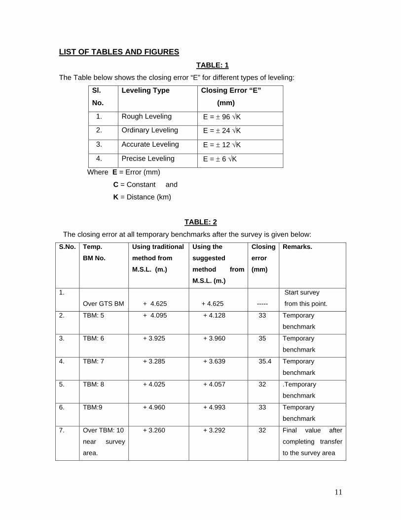
LIST OF TABLES AND FIGURES TABLE: 1
The Table below shows the closing error “E” for different types of leveling:
Sl. No.
Leveling Type Closing Error “E” (mm)
1. Rough Leveling E = ± 96 √K
2. Ordinary Leveling E = ± 24 √K
3. Accurate Leveling E = ± 12 √K
4. Precise Leveling E = ± 6 √K
Where E = Error (mm)
C = Constant and
K = Distance (km)
TABLE: 2 The closing error at all temporary benchmarks after the survey is given below:
S.No. Temp. BM No.
Using traditional method from M.S.L. (m.)
Using the suggested method from M.S.L. (m.)
Closing error (mm)
Remarks.
1.
Over GTS BM
+ 4.625
+ 4.625
-----
Start survey
from this point.
2. TBM: 5 + 4.095 + 4.128 33 Temporary
benchmark
3. TBM: 6 + 3.925 + 3.960 35 Temporary
benchmark
4. TBM: 7 + 3.285 + 3.639 35.4 Temporary
benchmark
5. TBM: 8 + 4.025 + 4.057 32 .Temporary
benchmark
6. TBM:9 + 4.960 + 4.993 33 Temporary
benchmark
7. Over TBM: 10
near survey
area.
+ 3.260 + 3.292 32 Final value after
completing transfer
to the survey area
12
Fig:1. An Automatic Level instrument used for transferring benchmark, by the traditional method.
Fig:2. A graduated leveling staff of 4 meters high, used along with Automatic Level
instrument, for transferring benchmark.

13
Fig: 3. Latest Electronic Total Station GPT-3002N model instrument, that can be used for
transferring G.T.S. benchmark value to survey area using the suggested method.
Fig:4. “Ceeducer” Differential Global Positioning System, which can be used for obtaining
accurate geographical and UTM co-ordinates of base stations “A” and “B”.
14
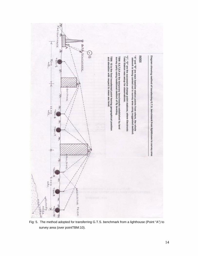
Fig: 5. The method adopted for transferring G.T.S. benchmark from a lighthouse (Point “A”) to
survey area (over pointTBM:10).
15
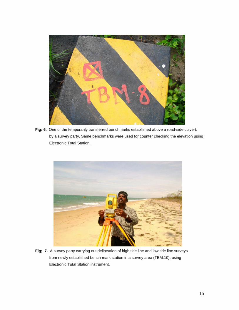
Fig: 6. One of the temporarily transferred benchmarks established above a road-side culvert,
by a survey party. Same benchmarks were used for counter checking the elevation using
Electronic Total Station.
Fig; 7. A survey party carrying out delineation of high tide line and low tide line surveys
from newly established bench mark station in a survey area (TBM:10), using
Electronic Total Station instrument.
16
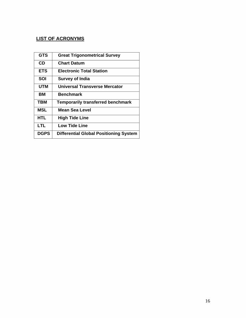
LIST OF ACRONYMS GTS Great Trigonometrical Survey
CD Chart Datum
ETS Electronic Total Station
SOI Survey of India
UTM Universal Transverse Mercator
BM Benchmark
TBM Temporarily transferred benchmark
MSL Mean Sea Level
HTL High Tide Line
LTL Low Tide Line
DGPS Differential Global Positioning System