Gt250 pe hmi manual (rev2)
32
rev. 2 GT-250-PE Operation
-
Upload
deltarailwaygroup -
Category
Automotive
-
view
888 -
download
26
description
The interface consists of 3 areas: overhead menu, central display for values and the bottom area for Status display and utility buttons
Transcript of Gt250 pe hmi manual (rev2)

rev. 2
GT-250-PE Operation
[GT-250-PE OPERATION] April 22, 2014
2
Contents
Human-Machine Interface ............................................................................................................... 3
Configuration Panel ..................................................................................................................... 5
Bend History - Operator ............................................................................................................... 9
User Selection Screen ............................................................................................................... 10
Authenticate - Operator ............................................................................................................. 11
Authenticate - Supervisor .......................................................................................................... 12
Bend History - Supervisor .......................................................................................................... 13
Report Viewer - Supervisor ........................................................................................................ 14
Operation - Hydraulic Check ...................................................................................................... 15
Operation - Prepare For Bending ............................................................................................... 16
Operation - Ready to Bend ........................................................................................................ 17
Operation - Bend in Progress ................................................................................................... 18
Operation - PDF Report ............................................................................................................. 19
Control Panel ................................................................................................................................ 20
1.Touch Screen Display: ........................................................................................................... 20
2. L.E.D. Lamps (for status display) ........................................................................................... 21
3. Selector Switches .................................................................................................................. 21
4. Push Buttons ......................................................................................................................... 22
5. Push Buttons with LED Lamps ....................................................................................... 23
6. Emergency Stop Button ......................................................................................................... 23
Auxiliary power.............................................................................................................................. 24
Monitoring video cam .................................................................................................................... 25
Calibration Sequence .................................................................................................................... 26
Calibration Sequence Application .............................................................................................. 31
[GT-250-PE OPERATION] April 22, 2014
3
Human-Machine Interface
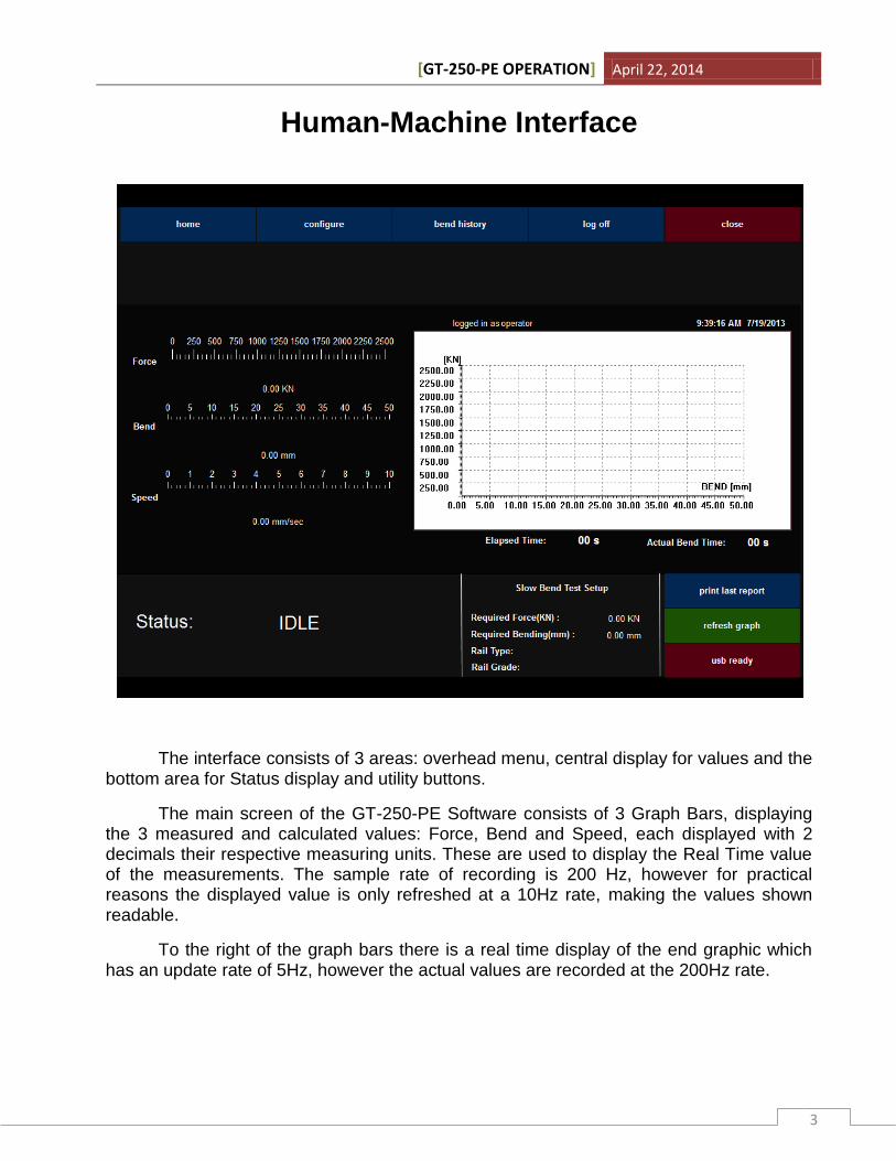
The interface consists of 3 areas: overhead menu, central display for values and the bottom area for Status display and utility buttons.
The main screen of the GT-250-PE Software consists of 3 Graph Bars, displaying the 3 measured and calculated values: Force, Bend and Speed, each displayed with 2 decimals their respective measuring units. These are used to display the Real Time value of the measurements. The sample rate of recording is 200 Hz, however for practical reasons the displayed value is only refreshed at a 10Hz rate, making the values shown readable.
To the right of the graph bars there is a real time display of the end graphic which has an update rate of 5Hz, however the actual values are recorded at the 200Hz rate.
[GT-250-PE OPERATION] April 22, 2014
4
Above the real time graphic display, the user type, date and time are displayed.
The Status area displays the current state of the machine, and has the following possible states: IDLE, Hydraulic Check, Prepare for Bending, Ready to Bend, Bend in Progress. Each will be discussed individually later on.
The Slow Bend Test Setup displays the current setup and information about the rail about to be tested as the Operator has configured it.
To the right of the "Slow Bend Test Setup" there are 2 buttons and 1 usb status display. The "print last report" button offers the Operator the ability to generate the PDF for the previous bend process. The process will be detailed later on. The "refresh graph" button refreshes the Real Time graph of the interface and should only be used for consecutive Bend Tests during the same session. If this is not used the result will be a comparative graph display of all the tests performed until this button is hit. This function is not available during the bend test. The" USB Ready" status is used to display the presence of a USB Mass storage device.
The overhead menu contains 5 buttons: "Home", "Configure", "Bend History", "Log Off" and "Close". These can be accessed through-out the entire operation of the interface with a few exceptions that will be detailed later on.
To return to the Main Screen you can always press the "Home" button.
[GT-250-PE OPERATION] April 22, 2014
5
Configuration Panel
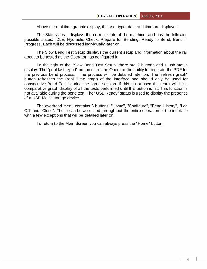
The configuration panel consists of 4 sub-menus that define both test and report parameters.
All sub-menus have 3 buttons: "Set" , "Clear" and "Close". The "Set" button validates the changes made to the inserted parameters and returns the operator to the previous screen. The "Clear" button resets all parameters and leaves a blank space. The "Close" button returns the operator to the previous screen.
The "Operator Details" sub-menu contains the Press Operator details that will be displayed on the final report. "Operator ID" is an exception as it is only used internally for database purposes. To complete each field press the keyboard symbol displayed in the
sub-menu window, this will bring up the On-Screen Keyboard. Press ↩ (Enter) after each field is complete.
As seen in the above image the Operator Details contains 4 fields:
- First Name (Reported) - Last Name (Reported) - Job Title (Reported) - Operator ID (Not Reported)
[GT-250-PE OPERATION] April 22, 2014
6
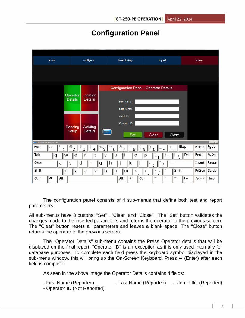
The "Location Details" sub-menu contains the fields to be completed for the location details that will be displayed on the final Report. The "Country" field can be completed with either the country initials or the full name of the country. The "Bend Location" field represents the location of the press when the test is performed. These are important details as environmental parameters can affect both rail and slow bend test results.
[GT-250-PE OPERATION] April 22, 2014
7
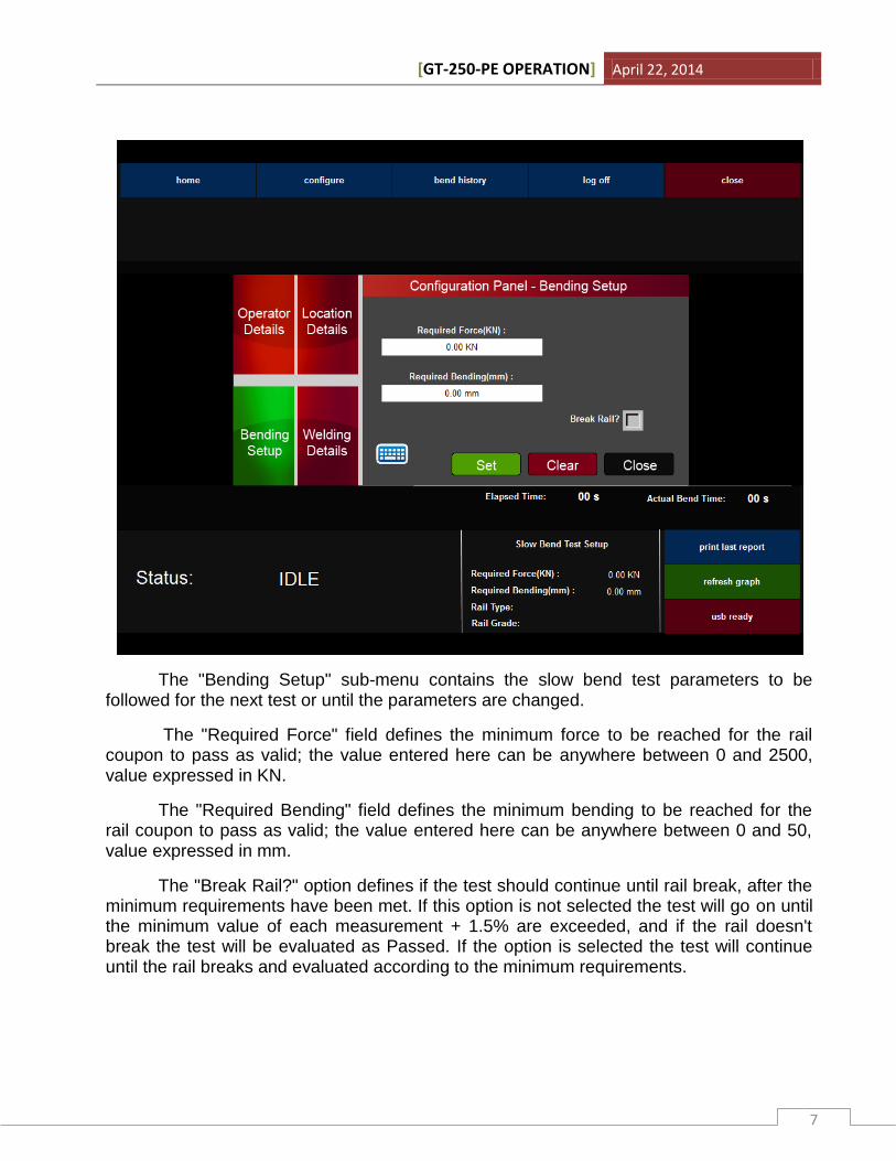
The "Bending Setup" sub-menu contains the slow bend test parameters to be followed for the next test or until the parameters are changed.
The "Required Force" field defines the minimum force to be reached for the rail coupon to pass as valid; the value entered here can be anywhere between 0 and 2500, value expressed in KN.
The "Required Bending" field defines the minimum bending to be reached for the rail coupon to pass as valid; the value entered here can be anywhere between 0 and 50, value expressed in mm.
The "Break Rail?" option defines if the test should continue until rail break, after the minimum requirements have been met. If this option is not selected the test will go on until the minimum value of each measurement + 1.5% are exceeded, and if the rail doesn't break the test will be evaluated as Passed. If the option is selected the test will continue until the rail breaks and evaluated according to the minimum requirements.
[GT-250-PE OPERATION] April 22, 2014
8
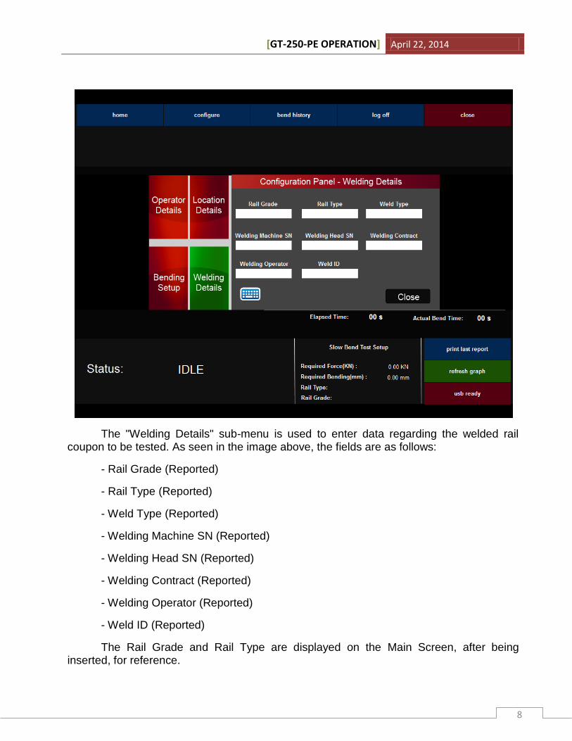
The "Welding Details" sub-menu is used to enter data regarding the welded rail coupon to be tested. As seen in the image above, the fields are as follows:
- Rail Grade (Reported)
- Rail Type (Reported)
- Weld Type (Reported)
- Welding Machine SN (Reported)
- Welding Head SN (Reported)
- Welding Contract (Reported)
- Welding Operator (Reported)
- Weld ID (Reported)
The Rail Grade and Rail Type are displayed on the Main Screen, after being inserted, for reference.
[GT-250-PE OPERATION] April 22, 2014
9
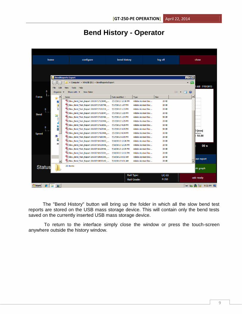
Bend History - Operator
The "Bend History" button will bring up the folder in which all the slow bend test reports are stored on the USB mass storage device. This will contain only the bend tests saved on the currently inserted USB mass storage device.
To return to the interface simply close the window or press the touch-screen anywhere outside the history window.
[GT-250-PE OPERATION] April 22, 2014
10
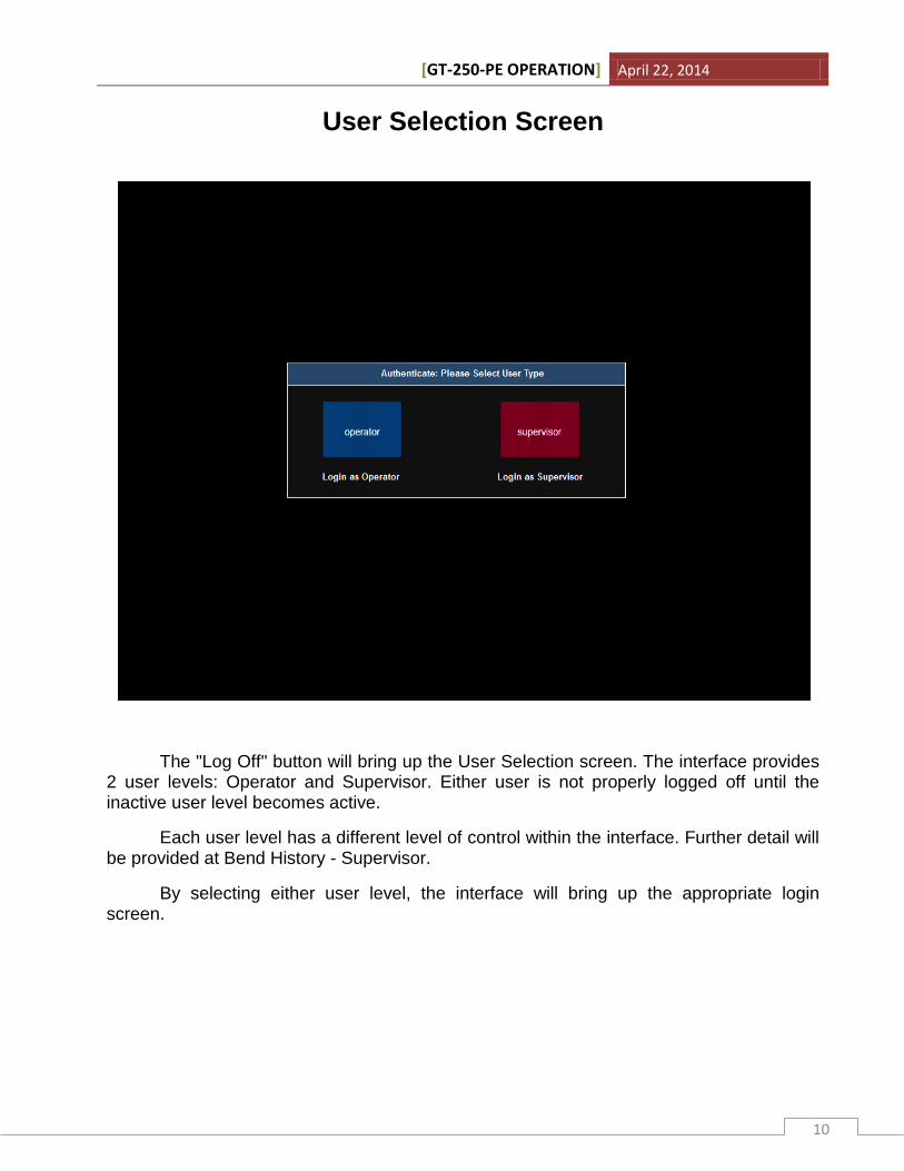
User Selection Screen
The "Log Off" button will bring up the User Selection screen. The interface provides 2 user levels: Operator and Supervisor. Either user is not properly logged off until the inactive user level becomes active.
Each user level has a different level of control within the interface. Further detail will be provided at Bend History - Supervisor.
By selecting either user level, the interface will bring up the appropriate login screen.
[GT-250-PE OPERATION] April 22, 2014
11
Authenticate - Operator
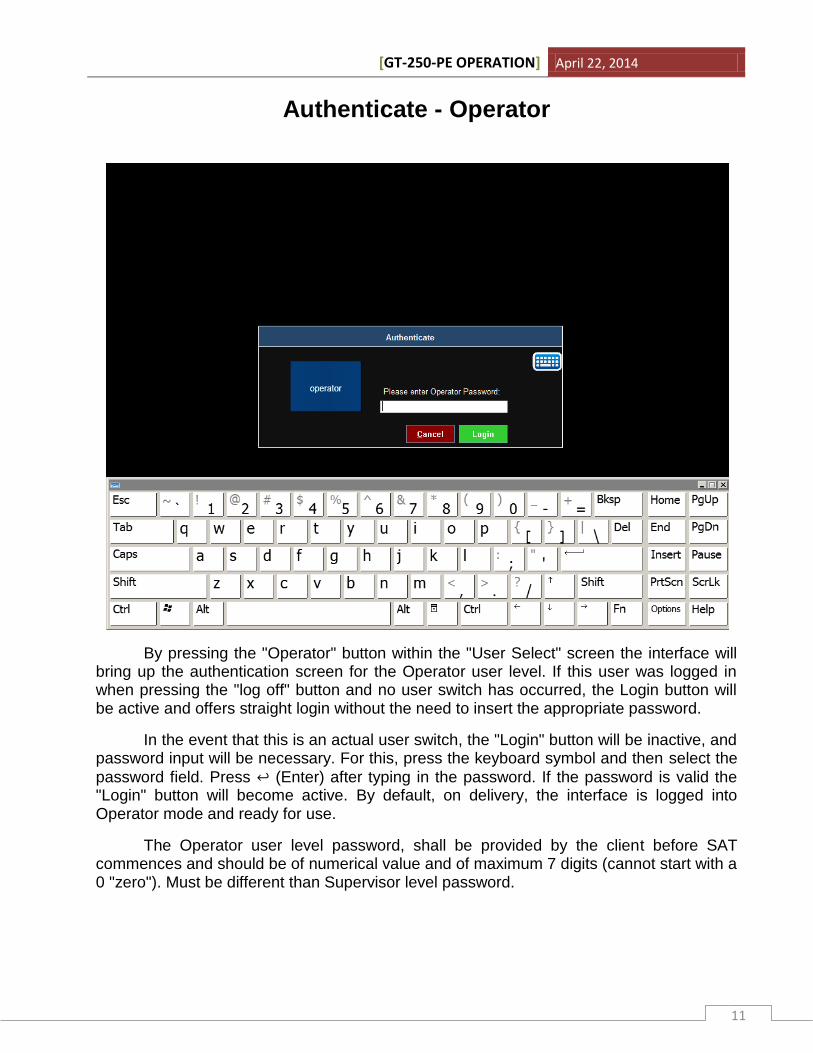
By pressing the "Operator" button within the "User Select" screen the interface will bring up the authentication screen for the Operator user level. If this user was logged in when pressing the "log off" button and no user switch has occurred, the Login button will be active and offers straight login without the need to insert the appropriate password.
In the event that this is an actual user switch, the "Login" button will be inactive, and password input will be necessary. For this, press the keyboard symbol and then select the
password field. Press ↩ (Enter) after typing in the password. If the password is valid the "Login" button will become active. By default, on delivery, the interface is logged into Operator mode and ready for use.
The Operator user level password, shall be provided by the client before SAT commences and should be of numerical value and of maximum 7 digits (cannot start with a 0 "zero"). Must be different than Supervisor level password.
[GT-250-PE OPERATION] April 22, 2014
12
Authenticate - Supervisor
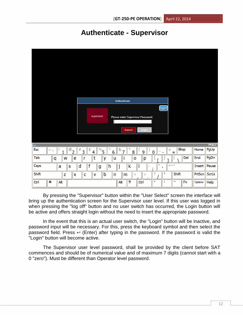
By pressing the "Supervisor" button within the "User Select" screen the interface will bring up the authentication screen for the Supervisor user level. If this user was logged in when pressing the "log off" button and no user switch has occurred, the Login button will be active and offers straight login without the need to insert the appropriate password.
In the event that this is an actual user switch, the "Login" button will be inactive, and password input will be necessary. For this, press the keyboard symbol and then select the
password field. Press ↩ (Enter) after typing in the password. If the password is valid the "Login" button will become active.
The Supervisor user level password, shall be provided by the client before SAT commences and should be of numerical value and of maximum 7 digits (cannot start with a 0 "zero"). Must be different than Operator level password.
[GT-250-PE OPERATION] April 22, 2014
13
Bend History - Supervisor
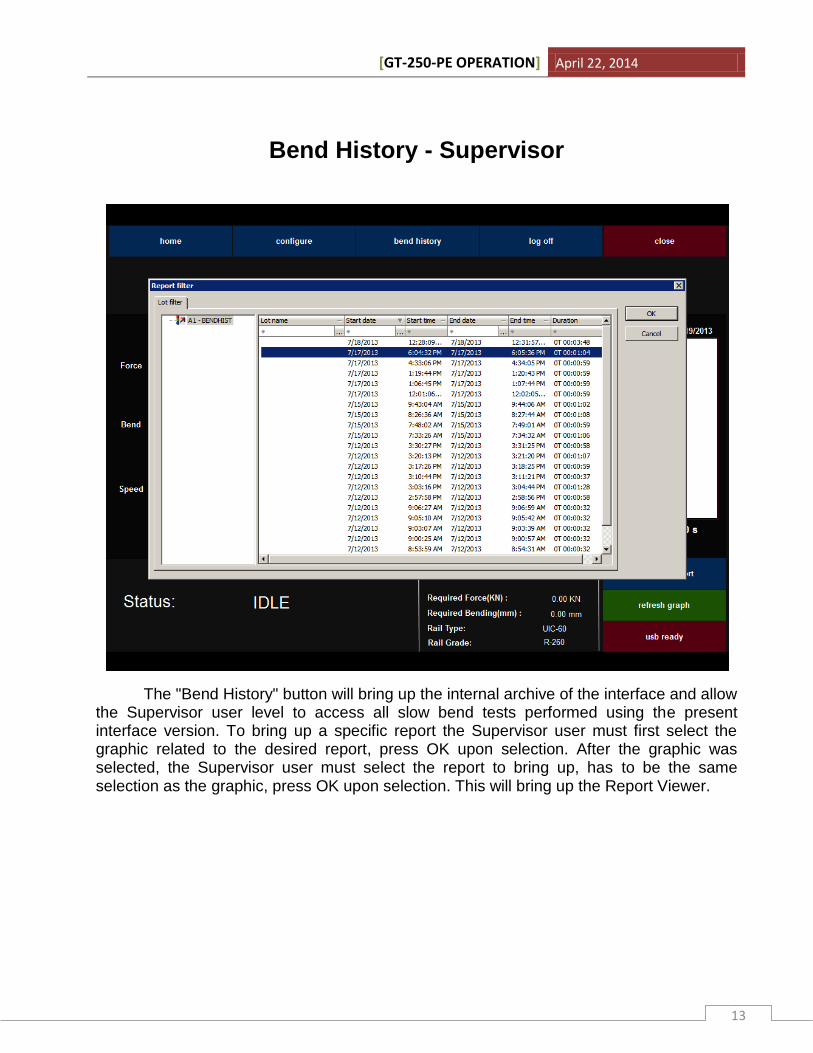
The "Bend History" button will bring up the internal archive of the interface and allow the Supervisor user level to access all slow bend tests performed using the present interface version. To bring up a specific report the Supervisor user must first select the graphic related to the desired report, press OK upon selection. After the graphic was selected, the Supervisor user must select the report to bring up, has to be the same selection as the graphic, press OK upon selection. This will bring up the Report Viewer.
[GT-250-PE OPERATION] April 22, 2014
14
Report Viewer - Supervisor
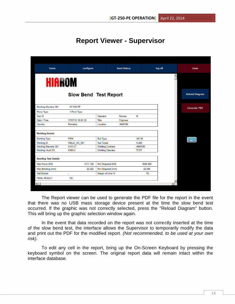
The Report viewer can be used to generate the PDF file for the report in the event that there was no USB mass storage device present at the time the slow bend test occurred. If the graphic was not correctly selected, press the "Reload Diagram" button. This will bring up the graphic selection window again.
In the event that data recorded on the report was not correctly inserted at the time of the slow bend test, the interface allows the Supervisor to temporarily modify the data and print out the PDF for the modified report. (Not recommended, to be used at your own risk).
To edit any cell in the report, bring up the On-Screen Keyboard by pressing the keyboard symbol on the screen. The original report data will remain intact within the interface database.
[GT-250-PE OPERATION] April 22, 2014
15
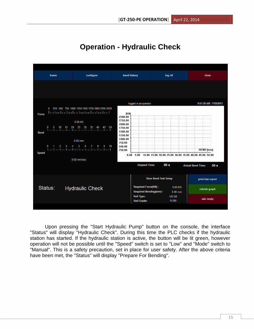
Operation - Hydraulic Check
Upon pressing the "Start Hydraulic Pump" button on the console, the interface "Status" will display "Hydraulic Check". During this time the PLC checks if the hydraulic station has started. If the hydraulic station is active, the button will be lit green, however operation will not be possible until the "Speed" switch is set to "Low" and "Mode" switch to "Manual". This is a safety precaution, set in place for user safety. After the above criteria have been met, the "Status" will display "Prepare For Bending".
[GT-250-PE OPERATION] April 22, 2014
16
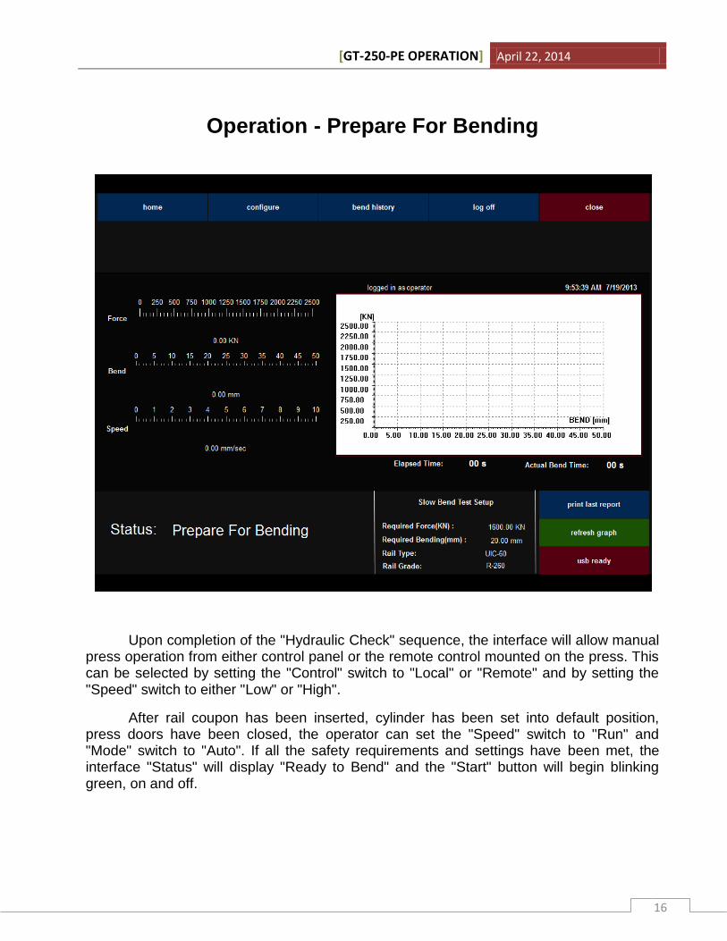
Operation - Prepare For Bending
Upon completion of the "Hydraulic Check" sequence, the interface will allow manual press operation from either control panel or the remote control mounted on the press. This can be selected by setting the "Control" switch to "Local" or "Remote" and by setting the "Speed" switch to either "Low" or "High".
After rail coupon has been inserted, cylinder has been set into default position, press doors have been closed, the operator can set the "Speed" switch to "Run" and "Mode" switch to "Auto". If all the safety requirements and settings have been met, the interface "Status" will display "Ready to Bend" and the "Start" button will begin blinking green, on and off.
[GT-250-PE OPERATION] April 22, 2014
17
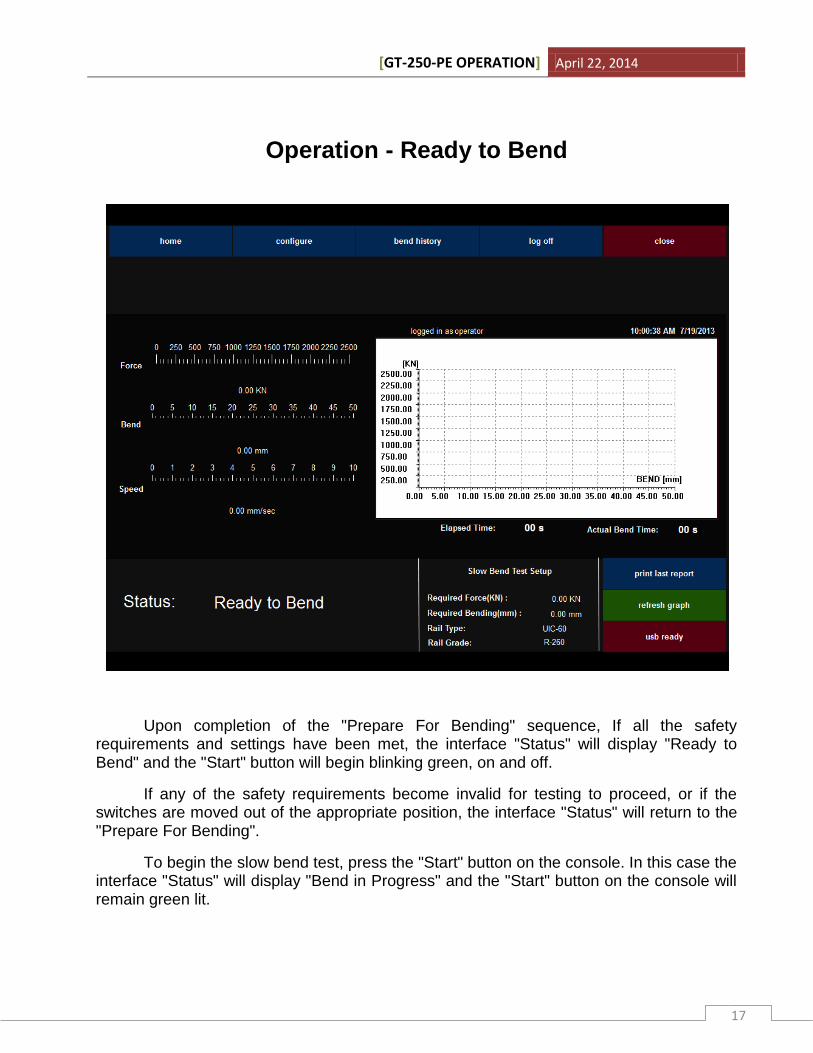
Operation - Ready to Bend
Upon completion of the "Prepare For Bending" sequence, If all the safety requirements and settings have been met, the interface "Status" will display "Ready to Bend" and the "Start" button will begin blinking green, on and off.
If any of the safety requirements become invalid for testing to proceed, or if the switches are moved out of the appropriate position, the interface "Status" will return to the "Prepare For Bending".
To begin the slow bend test, press the "Start" button on the console. In this case the interface "Status" will display "Bend in Progress" and the "Start" button on the console will remain green lit.

[GT-250-PE OPERATION] April 22, 2014
18
Operation - Bend in Progress
Upon completion of the "Ready to Bend " sequence, the bending program will become active and will continue until the minimum test requirements are met, any of the safety requirements become invalid, either "Stop" or "Emergency Stop" buttons are pressed. During this time, the Status Lamp mounted on the press is yellow lit.
The Main Screen of the interface will display the real time registered Force, Bend and Speed values. It also registers the "Elapsed Time", meaning total time since the "Start" button was pressed and bending program started; "Actual Bend Time" displays the time passed since the rail has started to bend. The time values are not used in the report, however they are stored in the database of the interface.
Do not close the interface or otherwise turn off the control panel during this time, unless an emergency situation occurs. Doing so can damage the database!
[GT-250-PE OPERATION] April 22, 2014
19
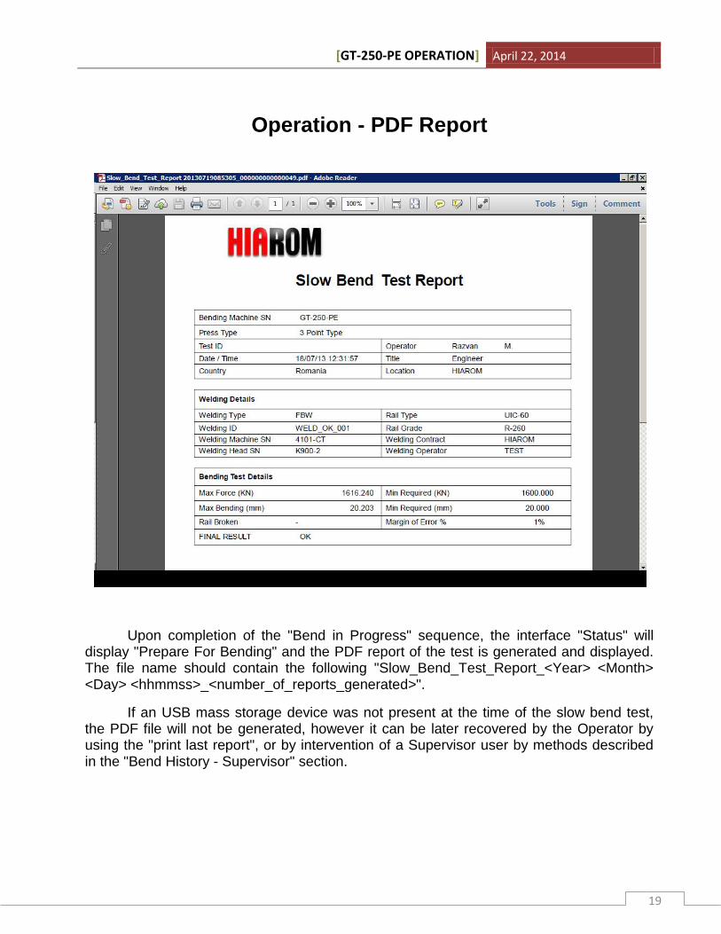
Operation - PDF Report
Upon completion of the "Bend in Progress" sequence, the interface "Status" will display "Prepare For Bending" and the PDF report of the test is generated and displayed. The file name should contain the following "Slow_Bend_Test_Report_<Year> <Month> <Day> <hhmmss>_<number_of_reports_generated>".
If an USB mass storage device was not present at the time of the slow bend test, the PDF file will not be generated, however it can be later recovered by the Operator by using the "print last report", or by intervention of a Supervisor user by methods described in the "Bend History - Supervisor" section.
[GT-250-PE OPERATION] April 22, 2014
20
Control Panel
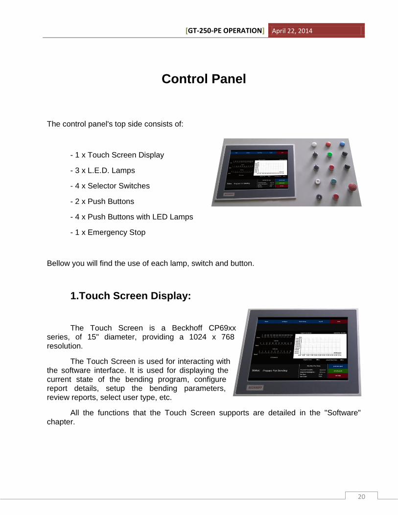
The control panel's top side consists of:
- 1 x Touch Screen Display
- 3 x L.E.D. Lamps
- 4 x Selector Switches
- 2 x Push Buttons
- 4 x Push Buttons with LED Lamps
- 1 x Emergency Stop
Bellow you will find the use of each lamp, switch and button.
1.Touch Screen Display:
The Touch Screen is a Beckhoff CP69xx series, of 15" diameter, providing a 1024 x 768 resolution.
The Touch Screen is used for interacting with the software interface. It is used for displaying the current state of the bending program, configure report details, setup the bending parameters, review reports, select user type, etc.
All the functions that the Touch Screen supports are detailed in the "Software" chapter.
[GT-250-PE OPERATION] April 22, 2014
21
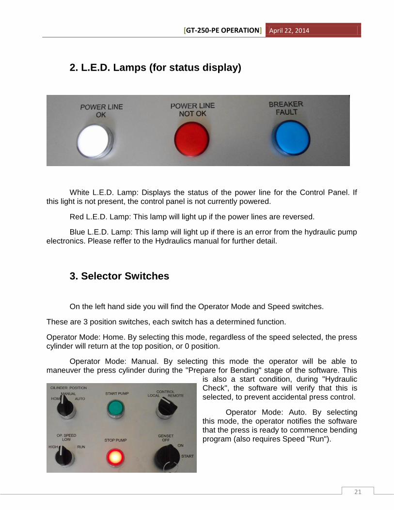
2. L.E.D. Lamps (for status display)
White L.E.D. Lamp: Displays the status of the power line for the Control Panel. If this light is not present, the control panel is not currently powered.
Red L.E.D. Lamp: This lamp will light up if the power lines are reversed.
Blue L.E.D. Lamp: This lamp will light up if there is an error from the hydraulic pump electronics. Please reffer to the Hydraulics manual for further detail.
3. Selector Switches
On the left hand side you will find the Operator Mode and Speed switches.
These are 3 position switches, each switch has a determined function.
Operator Mode: Home. By selecting this mode, regardless of the speed selected, the press cylinder will return at the top position, or 0 position.
Operator Mode: Manual. By selecting this mode the operator will be able to maneuver the press cylinder during the "Prepare for Bending" stage of the software. This
is also a start condition, during "Hydraulic Check", the software will verify that this is selected, to prevent accidental press control.
Operator Mode: Auto. By selecting this mode, the operator notifies the software that the press is ready to commence bending program (also requires Speed "Run").
[GT-250-PE OPERATION] April 22, 2014
22
Speed: High. By selecting this speed, the cylinder will move at the maximum speed (aprox 8mm / sec) during Manual Operation.
Speed: Low. By selecting this speed, the cylinder will move at a low speed (aprox 2.5 mm / sec). This allows safe functionality. This function is also needed during the "Hydraulic Check".
Speed: Run. By selecting this speed, the operator notifies the software that the press is ready to commence bending program (also requires Operator Mode "Auto").
On the right hand side you will find the Engine and Control switches. These are 2 position switches, each switch has a determined function.
Engine: Start. By selecting this option the engine of the Generator Set automatically starts (if the conditions in the Generator Set manual are met).
Engine: Stop. By selecting this option the engine of the Generator Set will enter the stop program and power down.
Control: Local. By selecting this option the operator will be able to control the movement of the cylinder from the control panel.
Control: Remote. By selecting this option the operator will be able to control the movement of the cylinder from the press remote control.
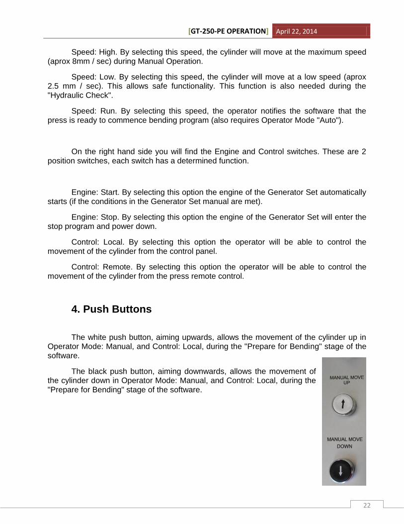
4. Push Buttons
The white push button, aiming upwards, allows the movement of the cylinder up in Operator Mode: Manual, and Control: Local, during the "Prepare for Bending" stage of the software.
The black push button, aiming downwards, allows the movement of the cylinder down in Operator Mode: Manual, and Control: Local, during the "Prepare for Bending" stage of the software.
[GT-250-PE OPERATION] April 22, 2014
23
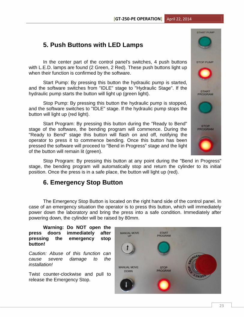
5. Push Buttons with LED Lamps
In the center part of the control panel's switches, 4 push buttons with L.E.D. lamps are found (2 Green, 2 Red). These push buttons light up when their function is confirmed by the software.
Start Pump: By pressing this button the hydraulic pump is started, and the software switches from "IDLE" stage to "Hydraulic Stage". If the hydraulic pump starts the button will light up (green light).
Stop Pump: By pressing this button the hydraulic pump is stopped, and the software switches to "IDLE" stage. If the hydraulic pump stops the button will light up (red light).
Start Program: By pressing this button during the "Ready to Bend" stage of the software, the bending program will commence. During the "Ready to Bend" stage this button will flash on and off, notifying the operator to press it to commence bending. Once this button has been pressed the software will proceed to "Bend in Progress" stage and the light of the button will remain lit (green).
Stop Program: By pressing this button at any point during the "Bend in Progress" stage, the bending program will automatically stop and return the cylinder to its initial position. Once the press is in a safe place, the button will light up (red).
6. Emergency Stop Button
The Emergency Stop Button is located on the right hand side of the control panel. In case of an emergency situation the operator is to press this button, which will immediately power down the laboratory and bring the press into a safe condition. Immediately after powering down, the cylinder will be raised by 80mm.
Warning: Do NOT open the press doors immediately after pressing the emergency stop button!
Caution: Abuse of this function can cause severe damage to the installation!
Twist counter-clockwise and pull to release the Emergency Stop.
[GT-250-PE OPERATION] April 22, 2014
24
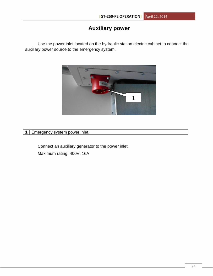
Auxiliary power
Use the power inlet located on the hydraulic station electric cabinet to connect the
auxiliary power source to the emergency system.
Connect an auxiliary generator to the power inlet.
Maximum rating: 400V, 16A
1 Emergency system power inlet.
1
[GT-250-PE OPERATION] April 22, 2014
25
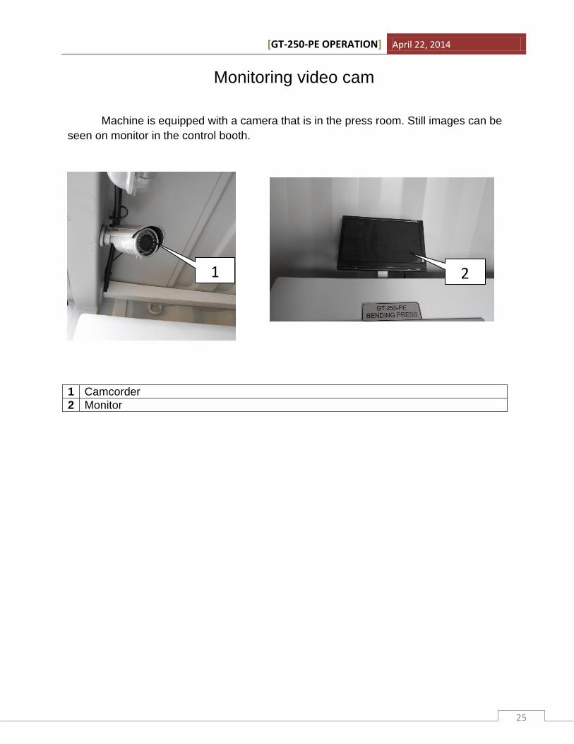
Monitoring video cam
Machine is equipped with a camera that is in the press room. Still images can be
seen on monitor in the control booth.
1 Camcorder
2 Monitor
1 2

[GT-250-PE OPERATION] April 22, 2014
26
Calibration Sequence
Calibration sequence for the GT-250-PE can be launched via the green “Calibration” button found on the main screen, only in Supervisor user level. This sequence is not automated, and must be performed by qualified personnel only.
Do not attempt to alter any values without a reference!
Once the above screen is shown the following data can be viewed: Total Displacement and Force (in KN).
Displacement Error %: Value in % for the displacement to compensate with in order to match the reference within 1% threshold. Compensation value is absolute in effect, hence the value should be altered in reference to current value (e.g. if the Displacement Error % is currently 1.0 % and there is an error of +2.0%, then the value must be altered to 3.0% in order to match the reference)
Force Error %: Value in % for the force calculation to be compensated with in order to match the reference within 1% threshold. Compensation value is absolute in effect,
[GT-250-PE OPERATION] April 22, 2014
27
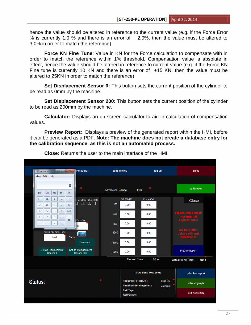
hence the value should be altered in reference to the current value (e.g. if the Force Error % is currently 1.0 % and there is an error of +2.0%, then the value must be altered to 3.0% in order to match the reference)
Force KN Fine Tune: Value in KN for the Force calculation to compensate with in order to match the reference within 1% threshold. Compensation value is absolute in effect, hence the value should be altered in reference to current value (e.g. if the Force KN Fine tune is currently 10 KN and there is an error of +15 KN, then the value must be altered to 25KN in order to match the reference)
Set Displacement Sensor 0: This button sets the current position of the cylinder to be read as 0mm by the machine.
Set Displacement Sensor 200: This button sets the current position of the cylinder to be read as 200mm by the machine.
Calculator: Displays an on-screen calculator to aid in calculation of compensation values.
Preview Report: Displays a preview of the generated report within the HMI, before it can be generated as a PDF. Note: The machine does not create a database entry for the calibration sequence, as this is not an automated process.
Close: Returns the user to the main interface of the HMI.
[GT-250-PE OPERATION] April 22, 2014
28
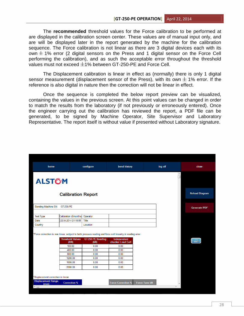
The recommended threshold values for the Force calibration to be performed at are displayed in the calibration screen center. These values are of manual input only, and are will be displayed later in the report generated by the machine for the calibration sequence. The Force calibration is not linear as there are 3 digital devices each with its own 1% error (2 digital sensors on the Press and 1 digital sensor on the Force Cell performing the calibration), and as such the acceptable error throughout the threshold values must not exceed 1% between GT-250-PE and Force Cell.
The Displacement calibration is linear in effect as (normally) there is only 1 digital sensor measurement (displacement sensor of the Press), with its own 1% error. If the reference is also digital in nature then the correction will not be linear in effect.
Once the sequence is completed the below report preview can be visualized, containing the values in the previous screen. At this point values can be changed in order to match the results from the laboratory (if not previously or erroneously entered). Once the engineer carrying out the calibration has reviewed the report, a PDF file can be generated, to be signed by Machine Operator, Site Supervisor and Laboratory Representative. The report itself is without value if presented without Laboratory signature.
[GT-250-PE OPERATION] April 22, 2014
29
Calibration Sequence Application:
In order to begin the Calibration sequence the user operating the machine must first log in as Supervisor (as described at page 12).
Once in Supervisor mode, the machine has all safety (except emergency stop) measures removed, and as such can press on any object without restraint.
Warning: Do not use the machine in this mode for normal operation as it can invalidate test results or cause harm to operating personnel.
Press the “Calibration” button located on the right hand side of the screen to proceed to the calibration menu. Once the calibration interface is displayed the sequence can begin.
Displacement: Displacement calibration must be initiated with the press cylinder fully extended. Once the HMI displays 200mm at Total Displacement, then the sequence can begin by moving the Cylinder up at LOW Speed. The thresholds for evaluation must be dictated by the laboratory providing the comparison equipment.
In the event that the displacement force on the HMI does not match the displacement measurement by the laboratory with an error of more than 1% then, the Displacement Error % field must be adjusted in value by the following formula:
Displ = Current Displacement Error %
Value = Updated value
GTD = Displacement Read by the GT-250-PE
LabD = Displacement Measured by the Laboratory Equipment
Value = Displ + ((LabD – GTD)*100 / LabD).
Example:
The displacement on screen is at 100mm, however the displacement measured by the laboratory is at 98mm, currently displacement Error % is at 0.0%.
Displ = 0
GTD = 100
LabD = 98
Value = 0 + ((98-100)*100/98) = -2.04% (can be set to 2.00% given 1% tolerance)
[GT-250-PE OPERATION] April 22, 2014
30
Example 2:
The displacement on screen is at 100mm, however the displacement measured by the laboratory is at 98mm, currently displacement Error % is at 2.04%.
Displ = -2.04
GTD = 100
LabD = 98
Value = -2.04 + ((98-100)*100/98) = -4.08%
Force: Force calibration must be initiated with the press cylinder at 0mm position, with the Force value displaying 0.00 KN. Once this is achieved, the operator must move the Cylinder Down on Low Speed until the first threshold value is reached (or slightly exceeded), and wait for the force reading to stabilize. Note: The Bend Press is not designed to keep the press cylinder still, and as such, the cylinder will slowly retract once the operator disengages the command to move down.
Once the reading on the force cell reaches the necessary value for the first threshold (e.g. 100KN) the operator must input the Force value as seen on screen in the appropriate field (GT-250-PE Force) and also the force value as displayed on the Force Cell / Force measurement equipment provided by laboratory.
In the event that the force value on the HMI does not match the force measurement by the laboratory with an error of more than 1% then, the Force Error % field must be adjusted in value by the following formula:
Displ = Current Force Error %
Value = Updated value
GTF = Force Read by the GT-250-PE
LabF = Force Measured by the Laboratory Equipment
Value = Displ + ((LabF – GTF)*100 / LabF).
Force calibration also allows for a fine tune of the displayed value with the Force KN Fine Tune (for difference in values of less than 30KN)
Value =Displ +(LabF – GTF)

[GT-250-PE OPERATION] April 22, 2014
31
Notes:

[GT-250-PE OPERATION] April 22, 2014
32
Disclaimer: Images in this manual have been selected to emphasize on certain aspects of the machine. Images may not reflect the end appearance of the product.