GSS-3000 Universal Gear Shift Sender Your new GSS-3000 ...
14
MAN# 650715:C 1 GSS-3000 Universal Gear Shift Sender Your new GSS-3000 includes: 393115 package contains: A. 1x – threaded rod (M3x9.5”) B. 2x – Ball joint end assembly C. 2x – M3-0.5mm nut D. 2x – Screw, 4-40 E. 4x – Nut, 4-40 F. 2x – Washer 5/16” G. 2x - 5/16” x 1” bolt H. 2x – Spacer, 3/8” ID I. 2x – M8x30mm bolt J. 1x – GM mounting plate K. 1x – Long gear shift sender arm L. 1x - C-4 mounting plate M. 1x - C-4 linkage connector N. 1x - C-6 mounting plate O. 1x - C-6 linkage connector P. 1x – GM linkage connector Q. 1x – Universal mounting plate R. 4x – Zip Ties
Transcript of GSS-3000 Universal Gear Shift Sender Your new GSS-3000 ...
MAN# 650715:C 1
GSS-3000 Universal Gear Shift Sender
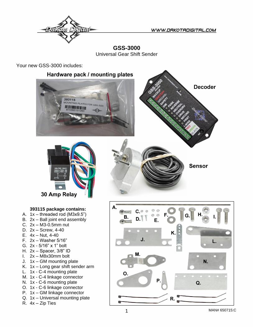
Your new GSS-3000 includes:
393115 package contains: A. 1x – threaded rod (M3x9.5”) B. 2x – Ball joint end assembly C. 2x – M3-0.5mm nut D. 2x – Screw, 4-40 E. 4x – Nut, 4-40 F. 2x – Washer 5/16” G. 2x - 5/16” x 1” bolt H. 2x – Spacer, 3/8” ID I. 2x – M8x30mm bolt J. 1x – GM mounting plate K. 1x – Long gear shift sender arm L. 1x - C-4 mounting plate M. 1x - C-4 linkage connector N. 1x - C-6 mounting plate O. 1x - C-6 linkage connector P. 1x – GM linkage connector Q. 1x – Universal mounting plate R. 4x – Zip Ties
MAN# 650715:C 2
Product Features
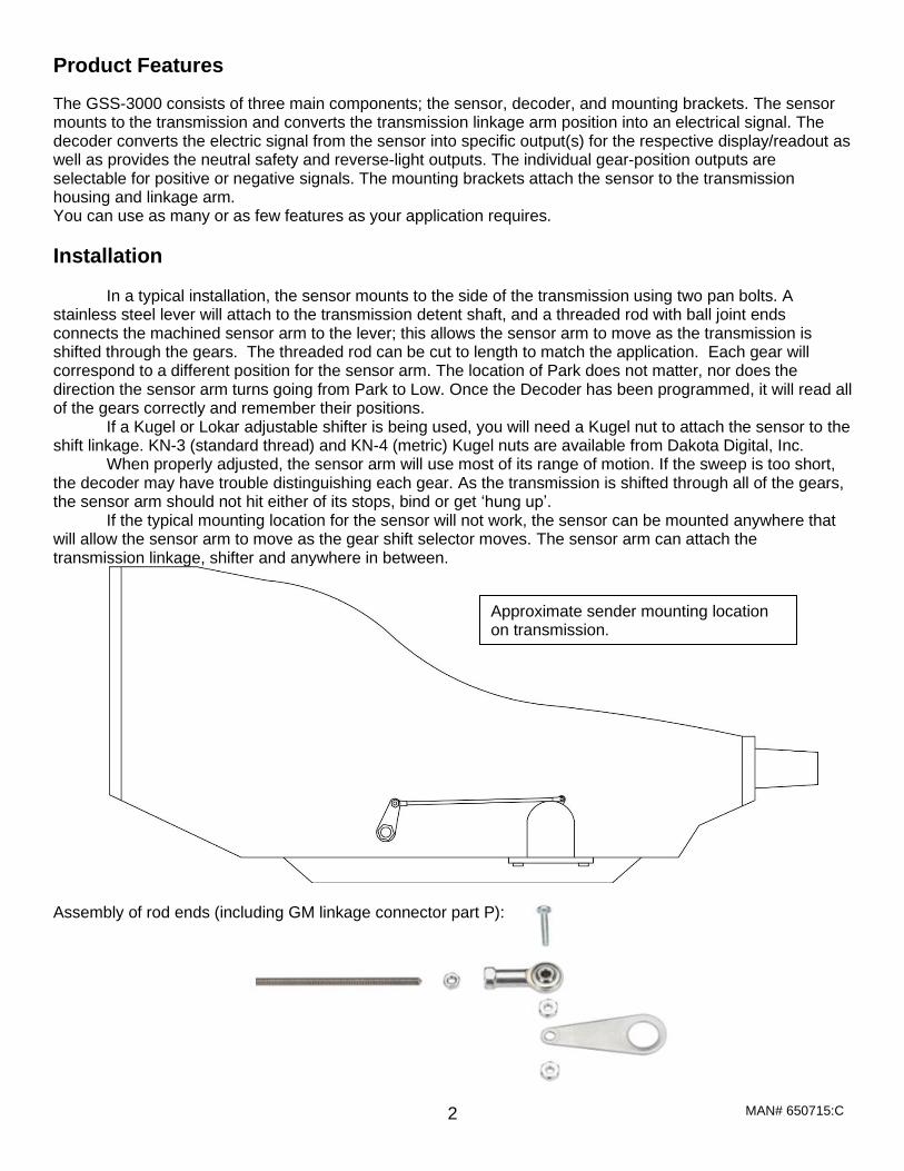
The GSS-3000 consists of three main components; the sensor, decoder, and mounting brackets. The sensor mounts to the transmission and converts the transmission linkage arm position into an electrical signal. The decoder converts the electric signal from the sensor into specific output(s) for the respective display/readout as well as provides the neutral safety and reverse-light outputs. The individual gear-position outputs are selectable for positive or negative signals. The mounting brackets attach the sensor to the transmission housing and linkage arm. You can use as many or as few features as your application requires.
Installation
In a typical installation, the sensor mounts to the side of the transmission using two pan bolts. A stainless steel lever will attach to the transmission detent shaft, and a threaded rod with ball joint ends connects the machined sensor arm to the lever; this allows the sensor arm to move as the transmission is shifted through the gears. The threaded rod can be cut to length to match the application. Each gear will correspond to a different position for the sensor arm. The location of Park does not matter, nor does the direction the sensor arm turns going from Park to Low. Once the Decoder has been programmed, it will read all of the gears correctly and remember their positions.
If a Kugel or Lokar adjustable shifter is being used, you will need a Kugel nut to attach the sensor to the shift linkage. KN-3 (standard thread) and KN-4 (metric) Kugel nuts are available from Dakota Digital, Inc.
When properly adjusted, the sensor arm will use most of its range of motion. If the sweep is too short, the decoder may have trouble distinguishing each gear. As the transmission is shifted through all of the gears, the sensor arm should not hit either of its stops, bind or get ‘hung up’.
If the typical mounting location for the sensor will not work, the sensor can be mounted anywhere that will allow the sensor arm to move as the gear shift selector moves. The sensor arm can attach the transmission linkage, shifter and anywhere in between.
Assembly of rod ends (including GM linkage connector part P):
Approximate sender mounting location on transmission.
MAN# 650715:C 3
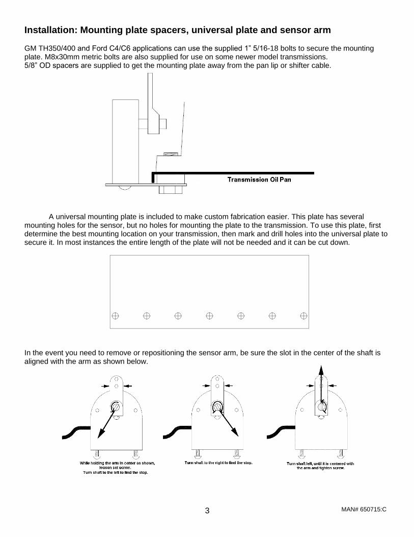
Installation: Mounting plate spacers, universal plate and sensor arm GM TH350/400 and Ford C4/C6 applications can use the supplied 1” 5/16-18 bolts to secure the mounting plate. M8x30mm metric bolts are also supplied for use on some newer model transmissions. 5/8” OD spacers are supplied to get the mounting plate away from the pan lip or shifter cable.
A universal mounting plate is included to make custom fabrication easier. This plate has several
mounting holes for the sensor, but no holes for mounting the plate to the transmission. To use this plate, first determine the best mounting location on your transmission, then mark and drill holes into the universal plate to secure it. In most instances the entire length of the plate will not be needed and it can be cut down.
In the event you need to remove or repositioning the sensor arm, be sure the slot in the center of the shaft is aligned with the arm as shown below.
MAN# 650715:C 4
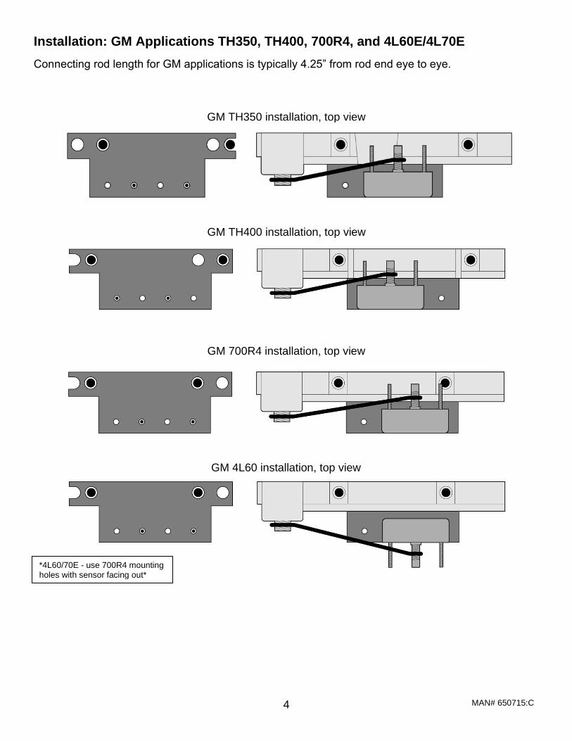
Installation: GM Applications TH350, TH400, 700R4, and 4L60E/4L70E
Connecting rod length for GM applications is typically 4.25” from rod end eye to eye.
GM 700R4 installation, top view
*4L60/70E - use 700R4 mounting holes with sensor facing out*
GM TH350 installation, top view
GM 4L60 installation, top view
GM TH400 installation, top view
MAN# 650715:C 5
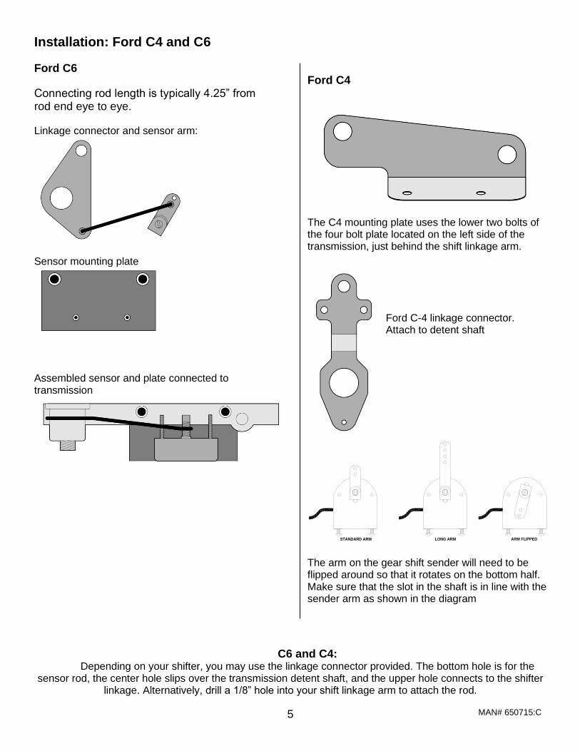
Installation: Ford C4 and C6
Ford C6
Connecting rod length is typically 4.25” from rod end eye to eye. Linkage connector and sensor arm:
Sensor mounting plate
Assembled sensor and plate connected to transmission
Ford C4
The C4 mounting plate uses the lower two bolts of the four bolt plate located on the left side of the transmission, just behind the shift linkage arm.
STANDARD ARM LONG ARM ARM FLIPPED
The arm on the gear shift sender will need to be flipped around so that it rotates on the bottom half. Make sure that the slot in the shaft is in line with the sender arm as shown in the diagram
C6 and C4: Depending on your shifter, you may use the linkage connector provided. The bottom hole is for the
sensor rod, the center hole slips over the transmission detent shaft, and the upper hole connects to the shifter linkage. Alternatively, drill a 1/8” hole into your shift linkage arm to attach the rod.
Ford C-4 linkage connector. Attach to detent shaft
MAN# 650715:C 6
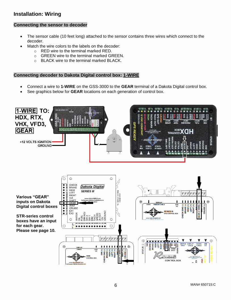
Installation: Wiring Connecting the sensor to decoder
• The sensor cable (10 feet long) attached to the sensor contains three wires which connect to the decoder.
• Match the wire colors to the labels on the decoder: o RED wire to the terminal marked RED. o GREEN wire to the terminal marked GREEN. o BLACK wire to the terminal marked BLACK.
Connecting decoder to Dakota Digital control box: 1-WIRE
• Connect a wire to 1-WIRE on the GSS-3000 to the GEAR terminal of a Dakota Digital control box.
• See graphics below for GEAR locations on each generation of control box.
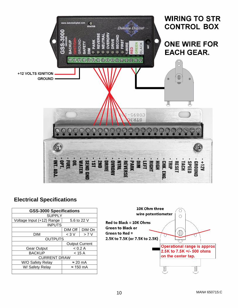
Various “GEAR” inputs on Dakota Digital control boxes. STR-series control boxes have an input for each gear. Please see page 10.
MAN# 650715:C 7
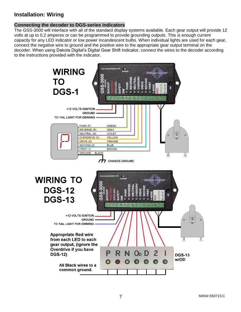
Installation: Wiring
Connecting the decoder to DGS-series indicators The GSS-3000 will interface with all of the standard display systems available. Each gear output will provide 12 volts at up to 0.2 amperes or can be programmed to provide grounding outputs. This is enough current capacity for any LED indicator or low power incandescent bulbs. When individual lights are used for each gear, connect the negative wire to ground and the positive wire to the appropriate gear output terminal on the decoder. When using Dakota Digital’s Digital Gear Shift Indicator, connect the wires to the decoder according to the instructions provided with the indicator.
MAN# 650715:C 8
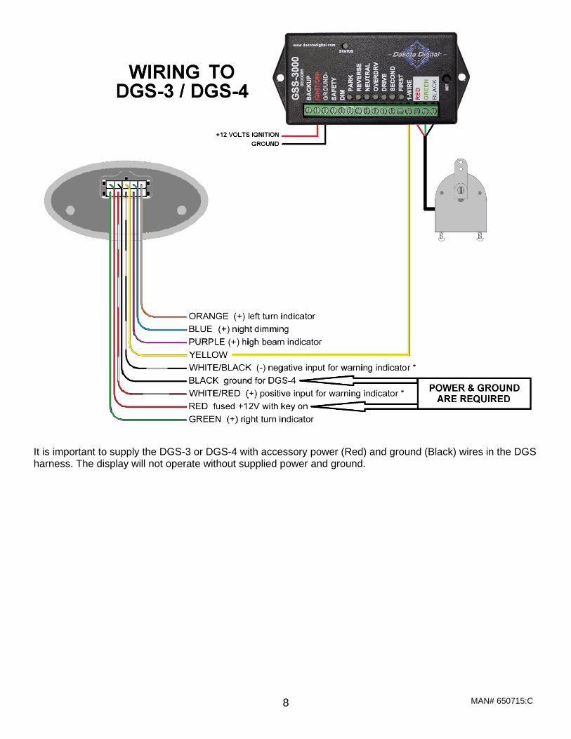
It is important to supply the DGS-3 or DGS-4 with accessory power (Red) and ground (Black) wires in the DGS harness. The display will not operate without supplied power and ground.
MAN# 650715:C 9
MAN# 650715:C 10
Electrical Specifications
GSS-3000 Specifications SUPPLY
Voltage Input (+12) Range 5.6 to 22 V
INPUTS
DIM Off DIM On
DIM < 3 V > 7 V
OUTPUTS
Output Current
Gear Output < 0.2 A
BACKUP < 15 A
CURRENT DRAW
W/O Safety Relay ≈ 20 mA
W/ Safety Relay ≈ 150 mA
MAN# 650715:C 11
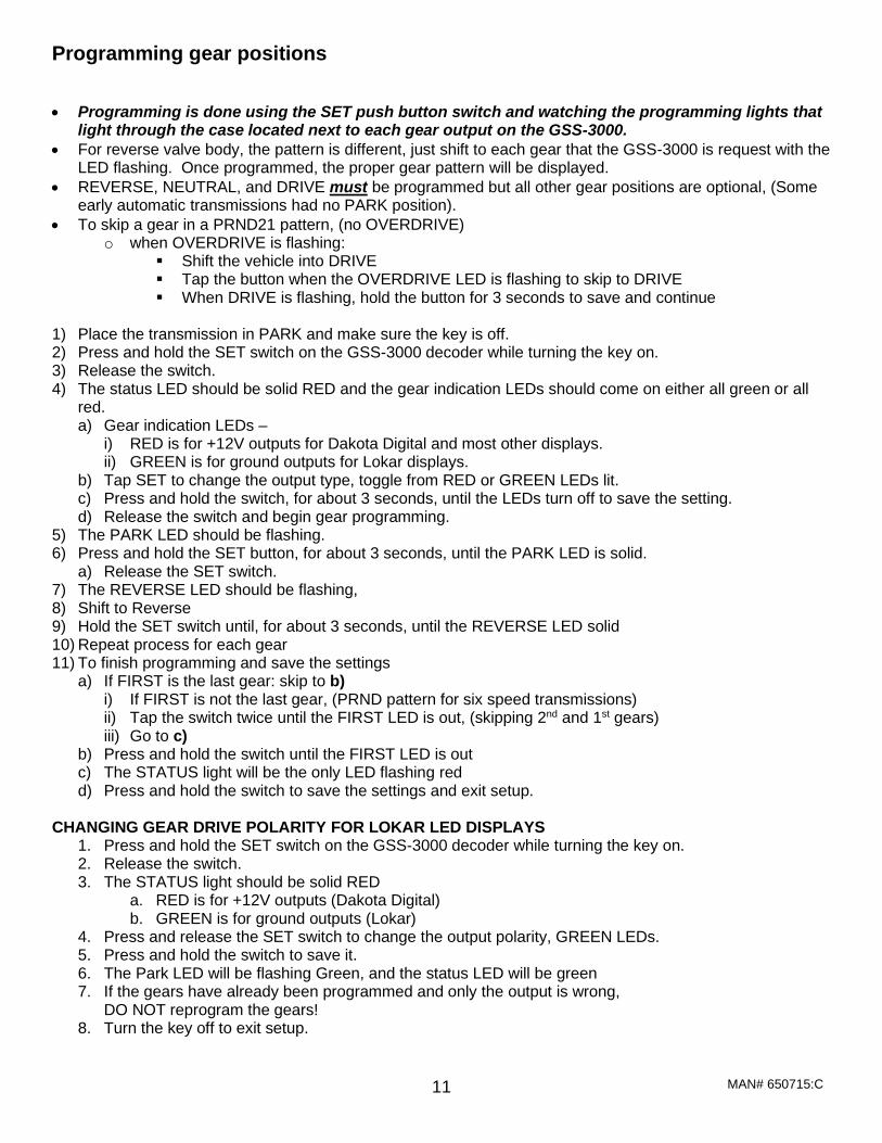
Programming gear positions
• Programming is done using the SET push button switch and watching the programming lights that
light through the case located next to each gear output on the GSS-3000.
• For reverse valve body, the pattern is different, just shift to each gear that the GSS-3000 is request with the LED flashing. Once programmed, the proper gear pattern will be displayed.
• REVERSE, NEUTRAL, and DRIVE must be programmed but all other gear positions are optional, (Some early automatic transmissions had no PARK position).
• To skip a gear in a PRND21 pattern, (no OVERDRIVE) o when OVERDRIVE is flashing:
▪ Shift the vehicle into DRIVE ▪ Tap the button when the OVERDRIVE LED is flashing to skip to DRIVE ▪ When DRIVE is flashing, hold the button for 3 seconds to save and continue
1) Place the transmission in PARK and make sure the key is off. 2) Press and hold the SET switch on the GSS-3000 decoder while turning the key on. 3) Release the switch. 4) The status LED should be solid RED and the gear indication LEDs should come on either all green or all
red. a) Gear indication LEDs –
i) RED is for +12V outputs for Dakota Digital and most other displays. ii) GREEN is for ground outputs for Lokar displays.
b) Tap SET to change the output type, toggle from RED or GREEN LEDs lit. c) Press and hold the switch, for about 3 seconds, until the LEDs turn off to save the setting. d) Release the switch and begin gear programming.
5) The PARK LED should be flashing. 6) Press and hold the SET button, for about 3 seconds, until the PARK LED is solid.
a) Release the SET switch. 7) The REVERSE LED should be flashing, 8) Shift to Reverse 9) Hold the SET switch until, for about 3 seconds, until the REVERSE LED solid 10) Repeat process for each gear 11) To finish programming and save the settings
a) If FIRST is the last gear: skip to b) i) If FIRST is not the last gear, (PRND pattern for six speed transmissions) ii) Tap the switch twice until the FIRST LED is out, (skipping 2nd and 1st gears) iii) Go to c)
b) Press and hold the switch until the FIRST LED is out c) The STATUS light will be the only LED flashing red d) Press and hold the switch to save the settings and exit setup.
CHANGING GEAR DRIVE POLARITY FOR LOKAR LED DISPLAYS
1. Press and hold the SET switch on the GSS-3000 decoder while turning the key on. 2. Release the switch. 3. The STATUS light should be solid RED
a. RED is for +12V outputs (Dakota Digital) b. GREEN is for ground outputs (Lokar)
4. Press and release the SET switch to change the output polarity, GREEN LEDs. 5. Press and hold the switch to save it. 6. The Park LED will be flashing Green, and the status LED will be green 7. If the gears have already been programmed and only the output is wrong,
DO NOT reprogram the gears! 8. Turn the key off to exit setup.
MAN# 650715:C 12
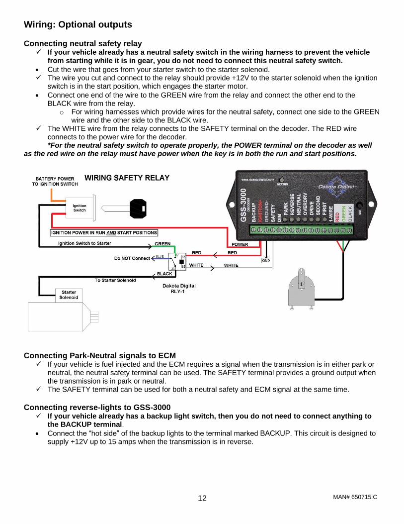
Wiring: Optional outputs Connecting neutral safety relay
✓ If your vehicle already has a neutral safety switch in the wiring harness to prevent the vehicle from starting while it is in gear, you do not need to connect this neutral safety switch.
• Cut the wire that goes from your starter switch to the starter solenoid. ✓ The wire you cut and connect to the relay should provide +12V to the starter solenoid when the ignition
switch is in the start position, which engages the starter motor.
• Connect one end of the wire to the GREEN wire from the relay and connect the other end to the BLACK wire from the relay.
o For wiring harnesses which provide wires for the neutral safety, connect one side to the GREEN wire and the other side to the BLACK wire.
✓ The WHITE wire from the relay connects to the SAFETY terminal on the decoder. The RED wire connects to the power wire for the decoder. *For the neutral safety switch to operate properly, the POWER terminal on the decoder as well
as the red wire on the relay must have power when the key is in both the run and start positions.
Connecting Park-Neutral signals to ECM ✓ If your vehicle is fuel injected and the ECM requires a signal when the transmission is in either park or
neutral, the neutral safety terminal can be used. The SAFETY terminal provides a ground output when the transmission is in park or neutral.
✓ The SAFETY terminal can be used for both a neutral safety and ECM signal at the same time.
Connecting reverse-lights to GSS-3000
✓ If your vehicle already has a backup light switch, then you do not need to connect anything to the BACKUP terminal.
• Connect the “hot side” of the backup lights to the terminal marked BACKUP. This circuit is designed to supply +12V up to 15 amps when the transmission is in reverse.
MAN# 650715:C 13
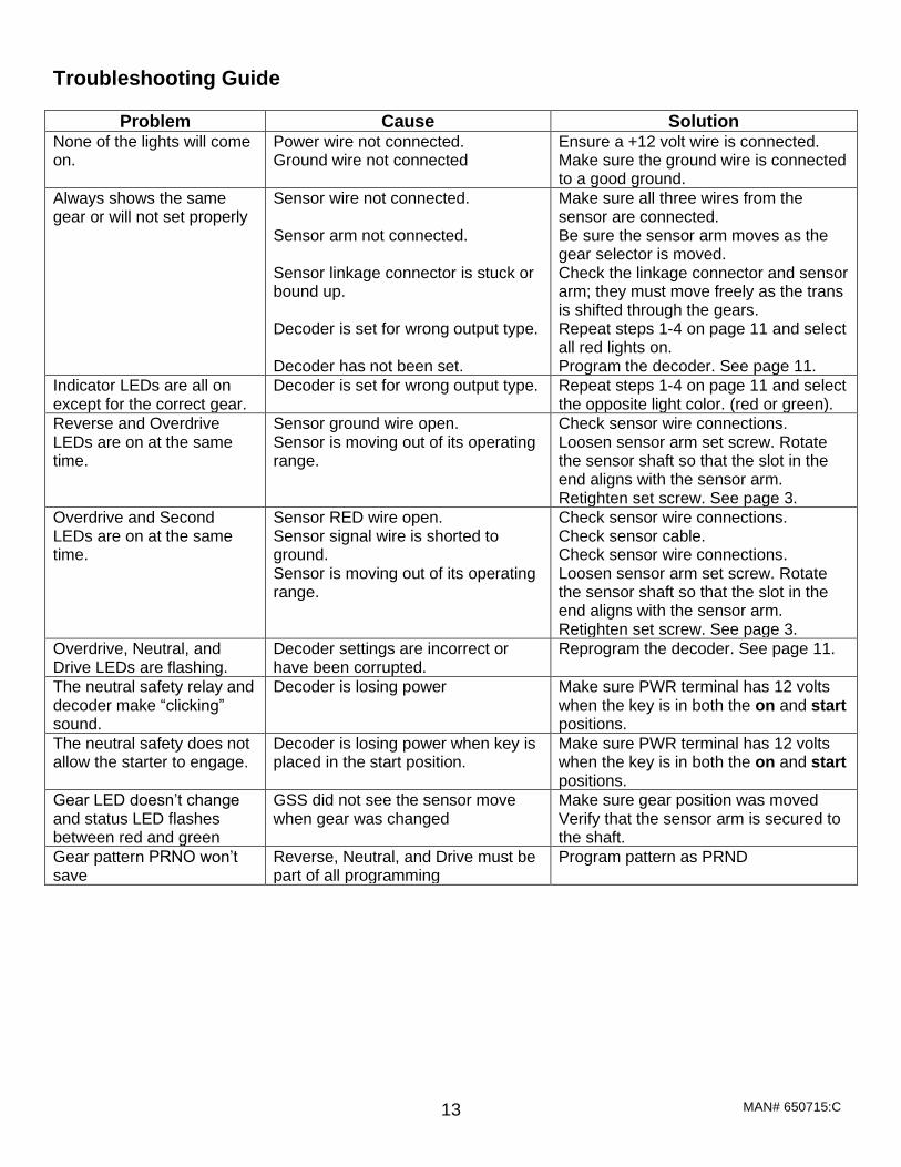
Troubleshooting Guide
Problem Cause Solution None of the lights will come on.
Power wire not connected. Ground wire not connected
Ensure a +12 volt wire is connected. Make sure the ground wire is connected to a good ground.
Always shows the same gear or will not set properly
Sensor wire not connected. Sensor arm not connected. Sensor linkage connector is stuck or bound up. Decoder is set for wrong output type. Decoder has not been set.
Make sure all three wires from the sensor are connected. Be sure the sensor arm moves as the gear selector is moved. Check the linkage connector and sensor arm; they must move freely as the trans is shifted through the gears. Repeat steps 1-4 on page 11 and select all red lights on. Program the decoder. See page 11.
Indicator LEDs are all on except for the correct gear.
Decoder is set for wrong output type. Repeat steps 1-4 on page 11 and select the opposite light color. (red or green).
Reverse and Overdrive LEDs are on at the same time.
Sensor ground wire open. Sensor is moving out of its operating range.
Check sensor wire connections. Loosen sensor arm set screw. Rotate the sensor shaft so that the slot in the end aligns with the sensor arm. Retighten set screw. See page 3.
Overdrive and Second LEDs are on at the same time.
Sensor RED wire open. Sensor signal wire is shorted to ground. Sensor is moving out of its operating range.
Check sensor wire connections. Check sensor cable. Check sensor wire connections. Loosen sensor arm set screw. Rotate the sensor shaft so that the slot in the end aligns with the sensor arm. Retighten set screw. See page 3.
Overdrive, Neutral, and Drive LEDs are flashing.
Decoder settings are incorrect or have been corrupted.
Reprogram the decoder. See page 11.
The neutral safety relay and decoder make “clicking” sound.
Decoder is losing power Make sure PWR terminal has 12 volts when the key is in both the on and start positions.
The neutral safety does not allow the starter to engage.
Decoder is losing power when key is placed in the start position.
Make sure PWR terminal has 12 volts when the key is in both the on and start positions.
Gear LED doesn’t change and status LED flashes between red and green
GSS did not see the sensor move when gear was changed
Make sure gear position was moved Verify that the sensor arm is secured to the shaft.
Gear pattern PRNO won’t save
Reverse, Neutral, and Drive must be part of all programming
Program pattern as PRND

MAN# 650715:C 14
SERVICE AND REPAIR DAKOTA DIGITAL offers complete service and repair of its product line. In addition, technical support is available to help you work through any questions or problems you may be having installing one of our products. Please read through the Troubleshooting Guide. There, you will find the solution to most problems. For additional support, please visit www.dakotadigital.com. A “Product Support” link will be found at the bottom of the home page. Should you ever need to send the unit back for repairs, please call our technical support line, (605) 332-6513, to request a Return Merchandise Authorization number.
• Package the product in a good quality box along with plenty of packing material. • Ship the product by a common carrier with tracking abilities. • Be sure to include the RMA number on the package. • Include a complete description of the problem, with RMA number, your full name and address (street
address preferred), and a telephone number where you can be reached during the day. • Any returns for warranty work must include a copy of the dated sales receipt from your place of
purchase. • Send no money. We will contact you for payment.
Dakota Digital 24 Month Warranty
DAKOTA DIGITAL warrants to the ORIGINAL PURCHASER of this product that should it, under normal use and condition, be proven defective in material or workmanship within 24 MONTHS FROM THE DATE OF PURCHASE, such defect(s) will be repaired or replaced at Dakota Digital’s option. This warranty does not cover nor extend to damage to the vehicle’s systems and does not cover removal or reinstallation of the product. This Warranty does not apply to any product or part thereof which in the opinion of the Company has been damaged through alteration, improper installation, mishandling, misuse, neglect, or accident. This Warranty is in lieu of all other expressed warranties or liabilities. Any implied warranties, including any implied warranty of merchantability, shall be limited to the duration of this written warranty. Any action for breach of any warranty hereunder, including any implied warranty of merchantability, must be brought within a period of 24 months from date of original purchase. No person or representative is authorized to assume, for Dakota Digital, any liability other than expressed herein in connection with the sale of this product.
WARNING: This product can expose you to chemicals including lead, which is known to the State of California to cause cancer and birth defects or other reproductive harm. For more information go to www.P65Warnings.ca.gov