GSP9200 Series Wheel Balancer Operation Instructions (English).pdfMaintenance & Calibration...
110
OPERATION INSTRUCTIONS Form 5393-T, 02-10 Supersedes Form 5393-T, 11-08 GSP9200 Series Computerized LCD Balancer (GSP9220) With SmartWeight ® Balancing Technology Software Version 3.1 © Copyright 2006 - 2010 Hunter Engineering Company
-
Upload
truonghanh -
Category
Documents
-
view
220 -
download
3
Transcript of GSP9200 Series Wheel Balancer Operation Instructions (English).pdfMaintenance & Calibration...

OPERATION INSTRUCTIONS Form 5393-T, 02-10 Supersedes Form 5393-T, 11-08
GSP9200 Series
Computerized LCD
Balancer(GSP9220)
With SmartWeight® Balancing Technology
Software Version 3.1
© Copyright 2006 - 2010 Hunter Engineering Company


OWNER INFORMATION
Model Number____________________________________________________________________ Software Version Number __________________________________________________________ Serial Number ____________________________________________________________________ Date Installed ____________________________________________________________________ Service and Parts Representative_____________________________________________________ Phone Number ___________________________________________________________________ Sales Representative ______________________________________________________________ Phone Number ___________________________________________________________________
Concept and Procedure Training Checklist
Trained Declined
Safety Precautions � � Quick-Thread®
AutoClamp® (optional) Autostart Servo-Stop
Maintenance & Calibration � � Cleaning, Lubrication, and Maintenance of Adaptors, Hub, and Shaft Calibrating the Balance Calibrating the Dataset Arms
Mounting the Wheel/Tire Assembly � � Verifying Mounting Repeatability with Centering Check Feature Cone Mounting Pressure Ring and Spacers Flange Plate and Cone Mounting
Wheel Balancing � � SmartWeight®
Standard Mixed Weights Adhesive Weights Split-Spoke RimScan
Do’s and Don’ts of Wheel Balancing � �
Individuals and Date Trained
__________________________________ __________________________________
__________________________________ __________________________________
__________________________________ __________________________________
__________________________________ __________________________________
__________________________________ __________________________________
__________________________________ __________________________________
__________________________________ __________________________________
__________________________________ __________________________________
__________________________________ __________________________________
__________________________________ __________________________________
__________________________________ __________________________________


CONTENTS
1. GETTING STARTED........................................................................................ 11.1 Introduction ................................................................................................................. 1
References............................................................................................................. 11.2 For Your Safety ........................................................................................................... 1
Hazard Definitions.................................................................................................. 1IMPORTANT SAFETY INSTRUCTIONS............................................................... 2Electrical................................................................................................................. 3Decal Information and Placement.......................................................................... 3
Right Side View ............................................................................................... 3Left Side View.................................................................................................. 4Back View........................................................................................................ 4
Specific Precautions/BDC Laser Indicator............................................................. 5Specific Precautions/HammerHead™ TDC Laser Indicator (Optional) ................. 5Specific Precautions/Power Source....................................................................... 5Turning Power ON/OFF......................................................................................... 6Equipment Installation and Service ....................................................................... 6Equipment Specifications....................................................................................... 7Safety Summary .................................................................................................... 7
Explanation of Symbols................................................................................... 71.3 GSP9200 Components ............................................................................................... 8
Standard Accessories for Quick-Thread® .............................................................. 9Standard Accessories for Optional Auto-Clamp™ ................................................ 9
1.4 Operating the Console ............................................................................................. 10
Using Softkeys ..................................................................................................... 10Using Control knob .............................................................................................. 10Primary Balancing Display ................................................................................... 11Resetting the Program......................................................................................... 11
2. BALANCING OVERVIEW .............................................................................. 132.1 Balance Forces ......................................................................................................... 13
Balancing Theory - Static Imbalance ................................................................... 13Balancing Theory - Couple Imbalance................................................................. 14
2.2 SmartWeight® Balancing Technology..................................................................... 15
Static and Dynamic Imbalance Sensitivity ........................................................... 152.3 SmartWeight Forces and Limits Feature................................................................ 16
2.4 SmartWeight® Dynamic Weight Planes .................................................................. 16
2.5 Using SmartWeight®
................................................................................................. 16
Switching from SmartWeight® to Traditional Dynamic Balancing Modes ..... 172.6 WeightSaver
® Wheel Balancing Feature ................................................................ 17
Weight Savings .................................................................................................... 182.7 SmartWeight Odometer............................................................................................ 19
Show Savings Summary...................................................................................... 202.8 On-Vehicle Wheel Installation Methods.................................................................. 22
Hub Centric .......................................................................................................... 22Lug Centric........................................................................................................... 22
3. BALANCING PROCEDURES ........................................................................ 253.1 Mounting the Wheel on the Balancer Spindle........................................................ 25
Installing the Wheel Manually .............................................................................. 25Installing the Wheel Using Quick-Thread® Wheel Clamping ............................... 26Installing the Wheel Using Auto-Clamp™ Wheel Clamping (Optional) ............... 26Mounting Error Detection Features...................................................................... 27Front/Back Cone Mounting .................................................................................. 27Using Plastic Wheel Mounting Washer................................................................ 28Cone/Flange Plate Mounting ............................................................................... 30Using the Pressure Ring and Spacers................................................................. 31
GSP9200 Series Wheel Balancer Operation Instructions CONTENTS � i

Pressure Ring................................................................................................ 31Spacers ......................................................................................................... 31
3.2 Balance Primary Screen........................................................................................... 32
3.3 Wheel Assembly Selection for Saving Spin Data .................................................. 33
Saving Spin Data ................................................................................................. 33Storing Measurements......................................................................................... 33Print Summary ..................................................................................................... 34
3.4 Balance Modes.......................................................................................................... 34
SmartWeight® Balancing Technology .................................................................. 35Dynamic Balancing – Traditional Balancing Mode .............................................. 35Static Balancing – Traditional Balancing Mode ................................................... 36
Static Balance Mode Reminder (Except Patch Balance) .............................. 363.5 Balancing Procedures for Specific Weight Types and Placement ...................... 37
AUTO MODE Balancing Using All Weight Types and Locations ........................ 37STANDARD Balancing Procedure Using Clip-On Weights ................................. 38MIXED WEIGHTS Balancing Procedure Using a Combination of Clip-On & Adhesive Weights ................................................................................................ 40ADHESIVE WEIGHTS Balancing Procedure Using Adhesive Weights .............. 42PATCH BALANCE® Procedure............................................................................ 44
3.6 Automatic Dataset® Arms Operation ...................................................................... 46
Automatic Weight Position Measurement............................................................ 47Manual Weight Position Measurement ................................................................ 47Measuring Dimensions for Standard Clip-on Weight Balancing.......................... 48Measuring Dimensions for Mixed Weights (Clip-on/Adhesive) Balance.............. 48Measuring Dimensions for Adhesive Weights Balancing .................................... 49
Servo-Aided Adhesive Weight Placement..................................................... 49Manual Adhesive Weight Placement............................................................. 50
CenteringCheck® Wheel Centering Feature Using Imbalance Forces and Location................................................................................................................ 51
4. BALANCING FEATURES AND OPTIONS.................................................... 554.1 Blinding and Rounding ............................................................................................ 55
4.2 TPMSpecs TM
Feature ............................................................................................... 55
4.3 Hunter Help Feature.................................................................................................. 56
4.4 Quick-Thread® Wheel Clamping .............................................................................. 58
4.5 Auto-Clamp™ Wheel Clamping (Optional)............................................................. 59
4.6 Motor Drive/Servo-Stop............................................................................................ 59
4.7 Spindle-Lok® Feature................................................................................................ 60
4.8 Hood Autostart Feature............................................................................................ 60
4.9 Loose Hub Detect Feature ....................................................................................... 60
4.10 Split Weight® Feature.............................................................................................. 60
Split Weight® Operation ....................................................................................... 61Correcting Large Imbalances............................................................................... 61
4.11 Split Spoke® Feature............................................................................................... 62
Hiding Adhesive Weight behind Spoke................................................................ 62Re-entering Similar Wheel after Split Spoke® is Enabled.................................... 64Placing Hidden Weight Inside of Hollow Spokes ................................................. 64
4.12 RimScan™ Wheel Profile Scanner........................................................................ 66
Setting Dimensions with RimScan....................................................................... 66Real-Time Predictions with RimScan and SmartWeight®.................................... 69
4.13 BDC Laser Adhesive Weight Locator ................................................................... 70
4.14 Optional HammerHead™
TDC Laser Adhesive Weight Locator ......................... 71
Specific Precautions / HammerHead™ TDC Laser System................................ 724.15 Print Summary ........................................................................................................ 73
5. EQUIPMENT INFORMATION........................................................................ 755.1 Software Identification ............................................................................................. 75
5.2 Program Cartridge Removal and Installation......................................................... 75
5.3 Balancer Set Up......................................................................................................... 76
Display Language ................................................................................................ 76Printer................................................................................................................... 76
ii � CONTENTS GSP9200 Series Wheel Balancer Operation Instructions

Printout Language................................................................................................ 76Printout Paper Size Selection .............................................................................. 76Hood Autostart Feature........................................................................................ 76Servo-Stop ........................................................................................................... 76Weight Units......................................................................................................... 76
5.4 Service Mode Setup and Features .......................................................................... 76
Set Date and Time ............................................................................................... 77Setting Up the Balance Limits.............................................................................. 77Main Selections.................................................................................................... 77
Setting Up the Weight Units .......................................................................... 77Setting Up the Ounce Round Amount........................................................... 77Setting Up the Gram Round Amount............................................................. 77Setting the Limits Displayed .......................................................................... 77
Non-SmartWeight Options ................................................................................... 78Setting Up the Ounce Blind Amount.............................................................. 78Setting Up the Gram Blind Amount ............................................................... 78
SmartWeight® Options - Setting Up the Force Limits .......................................... 78WeightSaver® Residual Goal ........................................................................ 78
Prompt for Wheel Assembly ID............................................................................ 78Spindle Type ........................................................................................................ 79HammerHead™ ................................................................................................... 79
5.5 Updating TPMS Specifications and Hunter Help Files.......................................... 79
If Software Version is Less than 3.0 - Locate Balancer Serial Number............... 79If Software Version is 3.0 or Greater - Retrieve User Name and Password from Balancer ............................................................................................................... 80Remove the TPMS Flash Drive ........................................................................... 80
Download Specifications ............................................................................... 81Upload TPMS Specifications and Hunter Help Files to the Balancer ........... 83
6. CALIBRATION AND MAINTENANCE........................................................... 876.1 Calibration Procedures ............................................................................................ 87
Balancer (3 Spin Procedure)................................................................................ 88Inner Dataset® Arm (Calibration Tool, 221-672-1, Required) .............................. 89Outer Dataset® Arm (Calibration Tool, 221-672-1, Required) ............................. 91Quick Calibration Check Procedure..................................................................... 93
6.2 Diagnostic Procedures............................................................................................. 93
Force Sensors...................................................................................................... 94Keys and Switches............................................................................................... 94Data Acquisition Circuits ...................................................................................... 94Motor Drive........................................................................................................... 94
6.3 Printing....................................................................................................................... 94
6.4 Cleaning the Console ............................................................................................... 94
6.5 Maintenance .............................................................................................................. 95
Spindle Hub Face and Shaft ................................................................................ 95BDC Laser Adhesive Weight Locator Maintenance or Service ........................... 95Optional HammerHead™ TDC Laser Clip-On Weight Locator Maintenance or Service ................................................................................................................. 95
6.6 Mounting Cone Maintenance................................................................................... 96
7. GLOSSARY.................................................................................................... 97
GSP9200 Series Wheel Balancer Operation Instructions CONTENTS � iii

iv � CONTENTS GSP9200 Series Wheel Balancer Operation Instructions

1. Getting Started
1.1 Introduction
This manual provides operation instructions and information required to operate the GSP9200 Series Balancer. Read and become familiar with the contents of this manual prior to operating the GSP9200.
The owner of the GSP9200 is solely responsible for arranging technical training. The GSP9200 is to be operated only by a qualified trained technician. Maintaining records of personnel trained is solely the responsibility of the owner and management.
This manual assumes the technician has already been trained in basic balancing procedures.
References
This manual assumes that you are already familiar with the basics of tire balancing. The first section provides the basic information needed to operate the GSP9200. The following sections contain detailed information about equipment operation and procedures. “Italics” are used to refer to specific parts of this manual that provide additional information or explanation. For example, Refer to “GSP9200 Components,” page 8. These references should be read for additional information to the instructions being presented.
1.2 For Your Safety
Hazard Definitions
Watch for these symbols:
CAUTION: Hazards or unsafe practices, which could result in minor personal injury or product or property damage.
WARNING: Hazards or unsafe practices, which could result in
severe personal injury or death.
DANGER: Immediate hazards, which will result in severe personal
injury or death.
These symbols identify situations that could be detrimental to your safety and/or cause equipment damage.
GSP9200 Series Wheel Balancer Operation Instructions 1. Getting Started � 1

IMPORTANT SAFETY INSTRUCTIONS Read all instructions before operating the GSP9200.Read and follow the instructions and warnings provided in the service, operation and specification documents of the products with which this GSP9200 is used (i.e., automobile manufacturers, tire manufacturers etc.). Do not operate equipment with a damaged cord or equipment that has been dropped or damaged until a Hunter Service Representative has examined it. Always unplug equipment from electrical outlet when not in use. Never use the cord to pull the plug from the outlet. Grasp plug and pull to disconnect. If an extension cord is necessary, a cord with a current rating equal to or more than that of the equipment should be used. Cords rated for less current than the equipment may overheat. Care should be taken to arrange the cord so that it will not be tripped over or pulled. Verify that the electrical supply circuit and the receptacle are properly grounded. To reduce the risk of electrical shock, do not use on wet surfaces or expose to rain. Verify the appropriate electrical supply circuit is the same voltage and amperage ratings as marked on the balancer before operating.
WARNING: DO NOT ALTER THE ELECTRICAL PLUG. Plugging the electrical plug
into an unsuitable supply circuit will damage the equipment and may
result in personal injury.
To reduce the risk of fire, do not operate equipment near open containers of flammable liquids (gasoline).Read and follow all caution and warning labels affixed to your equipment and tools. Misuse of this equipment can cause personal injury and shorten the life of the balancer. Keep all instructions permanently with the unit. Keep all decals, labels, and notices clean and visible. To prevent accidents and/or damage to the balancer, use only Hunter GSP9200 Series Vibration Control System recommended accessories. Use equipment only as described in this manual. Never stand on the balancer. Wear non-slip safety footwear when operating the balancer. Keep hair, loose clothing, neckties, jewelry, fingers, and all parts of body away from all moving parts. Do not place any tools, weights, or other objects on the safety hood while operating the balancer. ALWAYS WEAR OSHA APPROVED SAFETY GLASSES. Eyeglasses that have only impact resistant lenses are NOT safety glasses. Keep the safety hood and its safety interlock system in good working order. Verify that the wheel is mounted properly and that the wing nut is firmly tightened before spinning the wheel (or AutoClamp is engaged and secure). The safety hood must be closed before pressing the green “START” key, located on the right front corner of the console, to spin the wheel. Hood Autostart will cause the balancer shaft to spin automatically upon hood closure. For the next Autostart, the safety hood has to be lifted to the full up position and then closed. Raise safety hood only after wheel has come to a complete stop. If safety hood is raised before the spin is completed, the weight values will not be displayed. Do not let cord hang over any edge or contact fan blades or hot manifolds. The red “STOP” key, located on the right front corner of the LCD assembly, can be used for emergency stops.
DANGER: Never reach under the hood while the balancer is performing a runout
measurement or balance spin.
SAVE THESE INSTRUCTIONS
2 � 1. Getting Started GSP9200 Series Wheel Balancer Operation Instructions
Electrical
The GSP9200 is manufactured to operate at a specific voltage and amperage rating.
Make sure that the appropriate electrical supply circuit is of the same voltage and amperage ratings as marked on the balancer.
WARNING: DO NOT ALTER THE ELECTRICAL PLUG. Plugging the
electrical plug into an unsuitable supply circuit will
damage the equipment.
Make sure that the electrical supply circuit and the appropriate receptacle is installed with proper grounding.
To prevent the possibility of electrical shock injury or damage to the equipment when servicing the balancer, power must be disconnected by removing the power cord from the electrical power outlet.
After servicing, be sure the balancer ON/OFF switch is in the “O” (off) position before plugging the power cord into the electrical power outlet.
This device is rated as Class A for radiated emissions.
In the event of radio interference, the display read out may flicker - this is normal.
Decal Information and Placement
NOTE: Decals and their placement may vary due to balancer configuration and options.
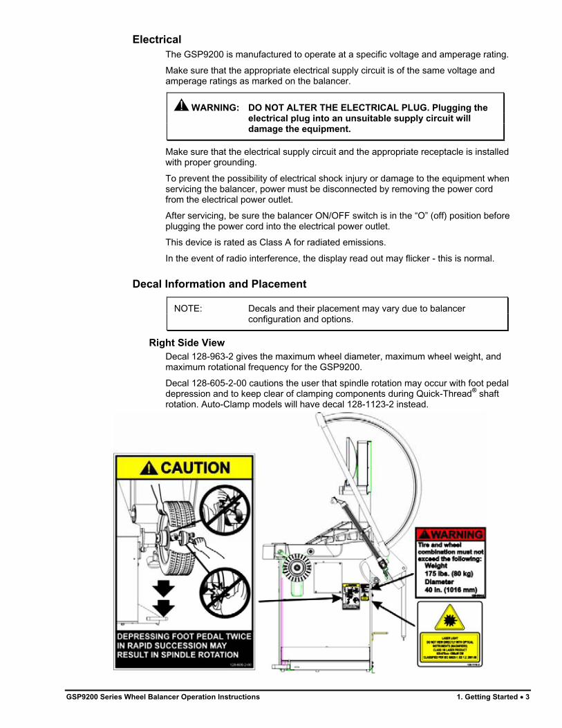
Right Side View
Decal 128-963-2 gives the maximum wheel diameter, maximum wheel weight, and maximum rotational frequency for the GSP9200.
Decal 128-605-2-00 cautions the user that spindle rotation may occur with foot pedal depression and to keep clear of clamping components during Quick-Thread® shaft rotation. Auto-Clamp models will have decal 128-1123-2 instead.
GSP9200 Series Wheel Balancer Operation Instructions 1. Getting Started � 3

Left Side View
Decal 128-391-2-00 cautions that the unit may automatically start upon closing of the hood when hood Autostart is enabled.
Decal 128-229-2 and decal 128-905-2 work in conjunction to caution the user to not remove the screw because of the risk of electrical shock.
Back View
Decal 128-907-2 warns the user to place the GSP9200 at garage floor level, and not in a recessed area, to avoid the possibility of flammable fume ignition.
Decal 128-229-2 and decal 128-905-2 work in conjunction to caution the user to not remove the screw because of the risk of electrical shock.
4 � 1. Getting Started GSP9200 Series Wheel Balancer Operation Instructions

Specific Precautions/BDC Laser Indicator
The BDC (Bottom Dead Center) Laser Indicator is a class 1M laser designed to aid in applying adhesive weights. The laser is not a field serviceable or adjustable part.
Use caution in regard to reflective materials around the laser and never look into the laser beam
Specific Precautions/HammerHead™ TDC Laser Indicator (Optional)
The TDC (Top Dead Center) Laser Indicator is a class 2M laser designed to aid in applying clip-on weights. The laser is not a field serviceable or adjustable part.
Use caution in regard to reflective materials around the laser and never look into the laser beam.
Specific Precautions/Power Source
The GSP9200 is intended to operate from a power source that will apply 230VAC +10% / -15%, 1 phase, 3 amp 50/60 Hz, power cable includes NEMA 20 amp plug, L6-20P, between the supply conductors of the power cord. The power cord supplied utilizes a twist lock connector, NEMA L6-20P. This machine must be connected to a 20 amp branch circuit. Please refer all power source issues to a certified electrician. Refer to “Installation Instructions for GSP9200 Series Vibration Control System,” Form 5110T.
GSP9200 Series Wheel Balancer Operation Instructions 1. Getting Started � 5

CAUTION: A protective ground connection, through the grounding conductor in the power cord, is essential for safe operation. Use only a power cord that is in good condition.
NOTE: For information on converting from single phase NEMA L6-20P plug to thee phase NEMA L15-20P plug refer toForm 5350T, “NEMA L6-20P to NEMA L15-20P Power Plug Conversion Instructions.”
Turning Power ON/OFF
The ON/OFF switch is located on the back of the balancer cabinet. To turn the balancer “ON,” press the “I” side of the ON/OFF switch. To turn the balancer “OFF,” press the “O” side of the ON/OFF switch.
The system requires about thirty-five seconds to “boot up.”
After the GSP9200 performs a self-check, the “Logo” screen will appear indicating the unit is ready for use.
Equipment Installation and Service
A factory-authorized representative should perform installation.
This equipment contains no user serviceable parts. All repairs must be referred to a qualified Hunter Service Representative.
NOTE: To replace program cartridge, refer to “Program Cartridge Removal and Installation,” page 75.
6 � 1. Getting Started GSP9200 Series Wheel Balancer Operation Instructions

Equipment Specifications
ElectricalVoltage: 230VAC +10% / -15%, 1 phase, 50/60 Hz,
power cable includes NEMA 20 amp plug, L6-20P
Amperage: 3 amperes Wattage: 795 watts (peak) AirAir Pressure Requirements: 100-175 PSI (6.9-12.0 bar)Approximate Air Consumption: 4 CFM (110 Liters/Minute) AtmosphericsTemperature: +32�F to +122�F (0�C to +50�C)Relative Humidity: Up to 95% Non-condensing Altitude: Up to 6000 ft. (1829 m) Sound Pressure Level Equivalent continuous A-weighted sound pressure at operator’s position does not exceed 70 dB (A).
Safety Summary
Explanation of Symbols
These symbols may appear on the equipment.
Alternating current.
Earth ground terminal.
Protective conductor terminal. l ON (supply) condition.
OFF (supply) condition.
Risk of electrical shock.
Stand-by switch.
Not intended for connection to public telecommunications network.
GSP9200 Series Wheel Balancer Operation Instructions 1. Getting Started � 7

1.3 GSP9200 Components
8 � 1. Getting Started GSP9200 Series Wheel Balancer Operation Instructions

Standard Accessories for Quick-Thread®
A. 106-82-2 Sleeve, Scratch Guard for Small Cup B. 175-353-1 Polymer Cup (4.5” O.D.) C. 76-433-3 Quick Take-Up Wing Nut with Handles D. 221-658-2 Hammer Heads (4) E. 46-320-2 Spacer F. 221-589-2 Weight Hammer/Pliers G. 221-659-2 Adhesive Weight Scraper H. 223-68-1 Pressure Ring I. 65-72-2 Calibration Weight
NOTE: Hunter wheel balancers do not include a standardized set of mounting adaptors.
For optional accessories, refer to Wheel Balancer Brochure, Form 3203T.
Standard Accessories for Optional Auto-Clamp™
Kit 20-2077-1
A. 106-82-2 Sleeve, Scratch Guard for Small Cup B. 175-353-1 Polymer Cup (4.5” O.D.) C. 184-81-1 Auto-Clamp Hub Assembly D. 221-658-2 Hammer Head Protectors (4) E. 46-320-2 Spacer F. 221-589-2 Weight Hammer/Pliers G. 20-1650-1 Rim Tags H. 221-659-2 Adhesive Weight Scraper I. 223-68-1 Pressure Ring J. 65-72-2 Calibration Weight
NOTE: Hunter wheel balancers do not include a standardized set of mounting adaptors.
For optional accessories, refer to Wheel Balancer Brochure, Form 3203T.
GSP9200 Series Wheel Balancer Operation Instructions 1. Getting Started � 9

1.4 Operating the Console
Using Softkeys
The “softkeys,” located on the LCD support console directly beneath the LCD, provide operator control of the balancer.
The four menu labels that appear at the bottom of each video screen are referred to as the “softkey labels.” Each label indicates the action that the program takes when the corresponding K1, K2, K3, or K4 key is pressed.
The display between the “K2” and “K3” labels indicates how many rows of labels are available. Most screens have only one or two rows, however more rows are possible. The green box indicates the row that is currently displayed.
The menu row is changed by pressing the menu shift key, . When this key is pressed, the menu labels change to the next row down. If the last row is currently displayed, the menu labels change to the first row.
Throughout this manual, the statement press “nnnnnnn” means press the softkey with the label “nnnnnnn.” If the required label is not on the current menu, press to change rows until the desired label is displayed.
K1 SOFTKEY
K2 SOFTKEY
MENU SHIFT
SOFTKEY K3 SOFTKEY
RESET
BUTTONSTART
BUTTONSTOP
BUTTON
K4 SOFTKEY
CONTROL
KNOB
Using Control knob
The control knob is located to the right of the softkeys. The control knob accesses the on-screen switches and manually inputs data. The available on-screen switches are dependent upon the setup configuration of the balancer.
10 � 1. Getting Started GSP9200 Series Wheel Balancer Operation Instructions

GSP9200 Series Wheel Balancer Operation Instructions 1. Getting Started � 11
Pushing in on the control knob cycles through the available on-screen switches on the current primary screen. Rotating the control knob clockwise or counter-clockwise changes the setting for the selected on-screen switch.
For example, in the “Balance” primary screen, pushing in on the control knob will cycle through the grams to ounces, the static and dynamic, and the SmartWeight®/Standardbalance screen switches. After selecting an on-screen switch, the setting may be selected by rotating the control knob. The “selected” switch is the one showing the hand.
Primary Balancing Display
NOTE: If SmartWeight mode is enabled, the balancer will always return to SmartWeight balancing upon dimension entry or a reset.
Resetting the Program
The wheel balancing program may be reset at anytime by using the key, located on the LCD support console directly beneath the LCD. To reset the balancer, press the reset key twice within a four-second period without pressing any other keys in-between. This prevents a single accidental keystroke from resetting the system.
When the balancer is reset, the information collected for the wheel balance in progress is erased and the display returns to the “Logo” screen.


2. Balancing Overview
2.1 Balance Forces
Balancing Theory - Static Imbalance
As the word static implies, the tire will be balanced when at rest. For example, if an unmoving assembly was centered on a cone and was balanced, it would be statically balanced. A “bubble balancer” is designed to statically balance a tire/wheel assembly.
IMBALANCE
FORCE
FRONT VIEW
STATIC IMBALANCE
CUPPING
Static imbalance is where there is one amount of weight located in the center of the tire/wheel assembly causing an imbalance. As the weight rotates, centrifugal forces are created causing the wheel to lift as the weight reaches top dead center. This lifting motion causes the tire/wheel assembly to move “up and down” creating a bounce to be felt. This static imbalance condition is evident by a “jiggle” or up-down movement of the steering wheel. These vibrations may also be apparent in the body, with or without steering wheel shake.
A statically imbalanced tire driven for an extended period may cause “cupping” in the tire’s tread, create vibration, and adversely effect handling.
Static balancing alone is a seldom-recommended procedure. For example, a single weight is commonly placed on the inner clip weight position for cosmetic purposes. This is not a recommended practice and usually insures the assembly is not properly dynamically balanced. The assembly may then experience side-to-side imbalance while in motion, causing a shimmy condition and objectionable vibration.
GSP9200 Series Wheel Balancer Operation Instructions 2. Balancing Overview � 13
Balancing Theory - Couple Imbalance
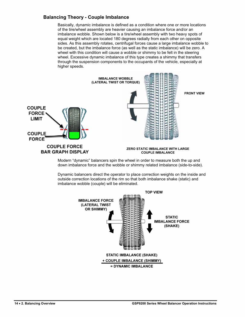
Basically, dynamic imbalance is defined as a condition where one or more locations of the tire/wheel assembly are heavier causing an imbalance force and/or an imbalance wobble. Shown below is a tire/wheel assembly with two heavy spots of equal weight which are located 180 degrees radially from each other on opposite sides. As this assembly rotates, centrifugal forces cause a large imbalance wobble to be created, but the imbalance force (as well as the static imbalance) will be zero. A wheel with this condition will cause a wobble or shimmy to be felt in the steering wheel. Excessive dynamic imbalance of this type creates a shimmy that transfers through the suspension components to the occupants of the vehicle, especially at higher speeds.
IMBALANCE WOBBLE
(LATERAL TWIST OR TORQUE)
FRONT VIEW
ZERO STATIC IMBALANCE WITH LARGE
COUPLE IMBALANCE
Modern “dynamic” balancers spin the wheel in order to measure both the up and down imbalance force and the wobble or shimmy related imbalance (side-to-side).
Dynamic balancers direct the operator to place correction weights on the inside and outside correction locations of the rim so that both imbalance shake (static) and imbalance wobble (couple) will be eliminated.
14 � 2. Balancing Overview GSP9200 Series Wheel Balancer Operation Instructions

2.2 SmartWeight® Balancing Technology
SmartWeight® is not a procedure. Instead, it measures the forces of side-to-side shimmy and up-and-down shake and computes weight to reduce these forces. This reduces the amount of weight, reduces time, reduces check spins, chasing weights, and saves the shop time and money.
SmartWeight® can reduce the number of steps in the balancing process. Not only does SmartWeight® give the customer a better riding vehicle, it also helps the environment by using less corrective weight, and speeds up the wheel balance process which saves the shop time and money.
Static and non-rounding modes are eliminated to simplify operation. Always enter two weight positions during wheel measurement in SmartWeight® mode. All other functions are identical to the traditional balancing method. SmartWeight®
automatically determines if a single weight is sufficient, or if two weight planes must be corrected.
SmartWeight® will also compute the amount of weight saved over time. A histogram of weight savings statistics can be viewed from the “wake-up” screen.
Static and Dynamic Imbalance Sensitivity
As a general rule of thumb, to achieve the best balance on an average sized tire and wheel assembly (15 x 7 inch rim):
Residual static imbalance should be less than 1/4 ounce (7 grams). Residual couple imbalance should be less than 3/4 ounce (21 grams) per plane.
Residual couple imbalance is preferred over remaining static imbalance.
It takes much more residual couple imbalance to cause a vibration than the same amount of static imbalance.
The larger the diameter used for weight placement, the smaller the amount of correction weight is required.
The wider the distance between the two weight placement locations, the smaller the amount of correction weight is required.
If static balance is the only option, always verify that the remaining couple residual imbalance is within acceptable tolerance.
NOTE: SmartWeight® balancing performs this check automatically.
For detailed information on adjustment and setup of modes of wheel balancing sensitivity see Chapter 4, Balancing Features and Options.
GSP9200 Series Wheel Balancer Operation Instructions 2. Balancing Overview � 15

2.3 SmartWeight Forces and Limits Feature
The static and couple forces are adjustable and show equivalent weight amounts on an example 15”x7” wheel. Static force is measured in oz. per inch. Couple force is measured in oz. per inch2. The defaults are preset for virtually all vehicle sensitivity limits.
2.4 SmartWeight® Dynamic Weight Planes
SmartWeight® requires the operator to enter two weight planes. This balancing method will automatically determine if one or both weight planes require a weight to be added. This eliminates “blinded” static single plane balancing, which alone may not be sufficient to solve vibration issues.
The GSP9200 balancer offers two primary ways to balance tires:
1. SmartWeight® balancing technology 2. Traditional balancing technology
Both of these methods can balance tires dynamically. The main difference is SmartWeight® will reduce the amount of corrective weight in a basic wheel balancing situation.
2.5 Using SmartWeight®
The SmartWeight® enabled balancing display varies slightly from the standard balancing display. The primary difference between the displays is the SmartWeight®
tire graphs that display the static and couple forces within a tire/wheel assembly.
The red-dotted line represents the acceptable amount of force the tire can have that will not result in a ride problem. Any forces below that line will be shown in green. Any forces that are above that level will be shown in red and indicate an excessive amount of force.
The traditional “static” and “dynamic” modes are eliminated. The traditional non-round off mode is eliminated. These modes are no longer necessary with SmartWeight®
balancing.
16 � 2. Balancing Overview GSP9200 Series Wheel Balancer Operation Instructions

Install the tire/wheel assembly as normal. Rim measurements are not required. Lower the hood and spin.
If SmartWeight® requires correction weights wheel dimensions will be required. Enter the dimensions using the dataset arms. The SmartWeight® tire graphs will display red for excessive forces and green for acceptable amounts of force. Prior to measurement the tire graphs will display no color.
The screen will display the amount and location of corrective weight necessary. Install the weights in the appropriate manner using the correct type of weight and lower the hood to re-spin and check the balance. Instead of displaying zeros in the weight display, SmartWeight® displays “OK,” indicating that the force levels are reduced to within the acceptable tolerances.
Switching from SmartWeight® to Traditional Dynamic Balancing Modes
At any time, SmartWeight® can be switched to standard balancing as long as both standard and SmartWeight® modes are enabled in setup.
Press the knob until SmartWeight® is highlighted. Once highlighted, press and hold the knob till the standard balance icons appear. Cycle back the same way.
2.6 WeightSaver® Wheel Balancing Feature
Essentially, SmartWeight® sets limits on the forces. WeightSaver® adjusts the percentage of these forces to either save weight, or have a more fine-tuned balance. With SmartWeight®, and bar graph in the green is within acceptable limits. WeightSaver® allows that bar graph window to be changed.
GSP9200 Series Wheel Balancer Operation Instructions 2. Balancing Overview � 17

The WeightSaver® wheel balancing feature is a percentage of the force limit intentionally left in the assembly to save weights.
WEIGHTSAVER
RESIDUAL GOAL
PERCENTAGE
The lower the value favors a lower residual force and a higher value favors weight savings. The following example is set at the default of 75%. A 75% residual goal means that WeightSaver® allows 75% of the maximum allowed couple force to remain. This saves more weight, saves time, and saves money.
Weight Savings
Select from the main logo screen to view a statistical page of weight savings classified by type of weight and rim diameter.
The page shows the amount of weight savings, highlighted in blue, using SmartWeight® balancing technology. The savings are shown in both actual weight and percentage.
The statistics can be cleared by selecting “Clear Data” from the second tier of softkeys. This could be used if tracking weight during a specific period. The “Clear Data” key may only be selected when in Service Mode. For more information refer to “Service Mode Setup and Features,” page 76.
Select “Print Screen” to print the weight savings displayed.
18 � 2. Balancing Overview GSP9200 Series Wheel Balancer Operation Instructions
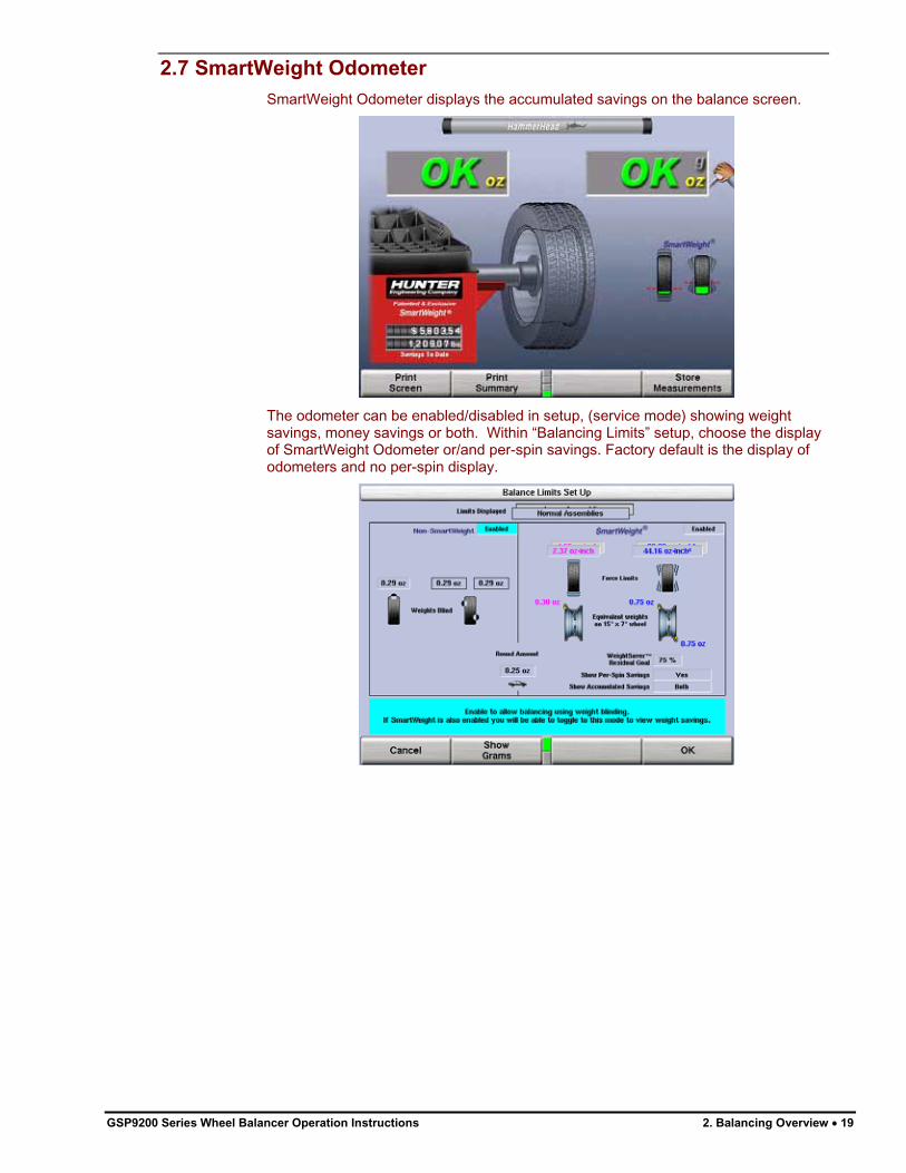
2.7 SmartWeight Odometer
SmartWeight Odometer displays the accumulated savings on the balance screen.
The odometer can be enabled/disabled in setup, (service mode) showing weight savings, money savings or both. Within “Balancing Limits” setup, choose the display of SmartWeight Odometer or/and per-spin savings. Factory default is the display of odometers and no per-spin display.
GSP9200 Series Wheel Balancer Operation Instructions 2. Balancing Overview � 19

Show Savings Summary
When the SmartWeight Odometer is present on screen, press the “Show Savings Summary” softkey for detailed explanation of savings.
NOTE: “Show Savings Summary” will be “projected savings” when selected time frame exceeds actual time of use.
A summary of the savings due to SmartWeight is displayed.
NOTE: “Set Assumptions” key available in “Service Mode” only.
Rolling the selector knob will change from Daily to Weekly to Monthly Yearly and Five Year savings.
Select “Print Screen” to print the weight savings displayed.
To enter actual weight costs and labor costs for cost savings calculation, select “Set Assumptions” (service mode) softkey for the “Smart Weight” screen.
NOTE: “Installation Date” must be entered for Investment Return calculations to function.
Enter requested information with control knob: rotate to change value and press to advance to next field.
20 � 2. Balancing Overview GSP9200 Series Wheel Balancer Operation Instructions

NOTE: “Set Assumptions” key available in “Service Mode” only.
Select “Enter Install Date” softkey to enter a date for the savings screen to properly show time to savings values. Select “Exit” softkey when done.
To view the payback of balancer from savings due to SmartWeight, select “Investment Return” softkey from the “Smart Weight” screen.
Rolling the selector knob will change from months to years of payback. Pressing the selector knob and then rolling it will change from percentage payback to total monetary value. Select “Print Screen” to print the weight savings displayed. Select “Exit” softkey when done.
To view additional details of savings due to SmartWeight, select “Show Details” softkey from the “Smart Weight” screen.
The page shows the amount of weight savings, highlighted in blue, using SmartWeight® balancing technology. The savings are shown in both actual weight and percentage. Select “Print Screen” to print the weight savings displayed. Select “Exit” softkey when done.
GSP9200 Series Wheel Balancer Operation Instructions 2. Balancing Overview � 21

NOTE: The statistics can be cleared by selecting the “Clear Data” softkey. This could be used if tracking weight during a specific period. The “Clear Data” key may only be selected when in Service Mode. For more information refer to “Service Mode Setup and Features,” page 76.
2.8 On-Vehicle Wheel Installation Methods
Hub Centric
A hub centric wheel is aligned to the hub by the center bore of the wheel. The vehicle weight rests on the hub bore. The clearance between the hub bore and the hub on a hub centric wheel is between 0.003 and 0.004 of an inch. A hub centric wheel is identified by removing the lug nuts (or bolts) and moving the wheel up, down, and side-to-side. If there is little or no movement, the wheel is centered by the hub.
To verify if the wheel is hub centric:
Remove the lug nuts (or bolts) and try to move the wheel up/down and side/side on the hub. If the wheel has no appreciable movement around or about the centerline of the hub, it should be considered hub centric. A hub centric wheel will have very little (0.003 – 0.004”) clearance or a slip fit to the hub.
Lug Centric
A lug centric wheel is identified by removing the lug nuts (or bolts) and moving the wheel up, down, and side-to-side. If movement around the hub is apparent, the wheel is centered on the vehicle by the lugs or studs of the axle flange.
22 � 2. Balancing Overview GSP9200 Series Wheel Balancer Operation Instructions

GSP9200 Series Wheel Balancer Operation Instructions 2. Balancing Overview � 23
TIP: When mounting a lug centric wheel to a vehicle, extreme centering care must be taken by ensuring the lug nuts (bolts) are tightened equally, while rotating the wheel.
“Step-torque” star pattern to proper torque specification.
To verify if the wheel is lug centric: Remove the lug nuts (or bolts) and try to move the wheel up/down and side/side on the hub. A lug centric wheel will display noticeable movement.


3. Balancing Procedures
3.1 Mounting the Wheel on the Balancer Spindle
CAUTION: Use only cones and accessories that are specifically designed for the GSP9200.
Since today’s vehicle designs are lighter and more sensitive to road feel, it is critical to achieve the best balance. Proper balance requires that the tire/wheel assembly be centered on the balancer. Tire/wheel assemblies can be balanced to zero, even with the tire/wheel assembly mounted off-center. The main objective of the balancer operator is to center the wheel on the hub and shaft, using the best available method. Mounting the wheel off-center creates incorrect measurements of imbalance and runout conditions.
Remove any existing wheel weights, rocks, and debris from the tire tread, and clean the center hole of the wheel. Inspect inside of wheel for excessive accumulation of dirt and debris. Remove if necessary before balancing.
Accurate balancing depends on accurately centering the wheel. Choose the proper wheel mounting cone by placing it in the center hole of the wheel to be balanced.
NOTE: If the basic cone and adaptors do not fit the wheel, additional centering adaptors will be necessary. A wheel that cannot be properly centered, cannot be properly balanced. All balancers require additional centering adaptors to properly center certain types of wheels. For additonal information, refer to Form 3203T for optional accessories.
Installing the Wheel Manually
With the safety hood open, place the wheel mounting cone on the spindle shaft against the captivated spring. Position the wheel with the inside surface facing the balancer, centered on the cone.
Install the plastic clamping cup and wing nut on the spindle shaft against the wheel and secure the entire assembly by firmly tightening the wing nut.
Depress and hold down the Spindle-Lok® foot pedal while tightening the wing nut. Holding the shaft locked while tightening the wing nut improves centering accuracy.
Slowly roll the wheel towards you while tightening the wing nut. This improves accurate wheel centering, since the wheel is allowed to roll up the taper of the cone as opposed to forcing it to slide up the cone.
GSP9200 Series Wheel Balancer Operation Instructions 3. Balancing Procedures � 25

Installing the Wheel Using Quick-Thread® Wheel Clamping
WARNING: Keep clear of clamping components during Quick-
Thread® shaft rotation.
Lift the wheel assembly onto the shaft as normal without threading on the wing nut.
With the left hand, hold the rim over the cone to remove the weight of the rim from the spindle and to allow maximum Quick-Thread® wing nut travel.
Place the wing nut on the spindle and rotate one full turn onto the spindle threads.
With the right hand, hold one handle of the wing nut while lifting the rim.
NOTE: Heavier wheel assemblies may require extra lifting to prevent the software limited motor torque control from stopping the rotation of the spindle.
Tap the foot pedal twice and the spindle will rotate to install the wing nut to save threading time.
A single tap within the first three seconds of rotation will reverse the direction of rotation. A single tap after the first three seconds of rotation will stop rotation.
Quick-Thread® spindle rotation will stop when the clamping components contact the wheel, or when the foot brake is applied for more than half of a second.
CAUTION: Quick-Thread® does not tighten the wing nut! In Quick-Thread® rotation, torque allowed is minimal. Therefore, the wing nut must still be hand-tightened before balancing.
Installing the Wheel Using Auto-Clamp™ Wheel Clamping (Optional)
With the safety hood open, place the wheel mounting cone on the spindle shaft against the captivated spring. Position the wheel with the inside surface facing the balancer, centered on the cone.
Install the plastic clamping cup and Auto-Clamp™ device by sliding onto the spindle shaft with the clamping cup pressed against the wheel. Rotate the Auto-Clamp assembly until it locks into place on the spindle. Secure the wheel by tapping the Spindle-Lok® foot pedal twice which will engage the pneumatic powered spindle sliding the Auto-Clamp assembly tightly against the wheel.
To remove the Auto-Clamp assembly, slightly tap the Spindle-Lok® foot pedal twiceto release the pneumatically powered spindle. Squeeze the levers to disconnect the Auto-Clamp locks from the spindle, and slide the assembly off the spindle.
26 � 3. Balancing Procedures GSP9200 Series Wheel Balancer Operation Instructions

Mounting Error Detection Features
To verify that the tire/wheel assembly is centering, remount the tire/wheel assembly and observe the results. Do any of the following conditions occur?
� Weight amount varies excessively
� Weight location changes
If any of these conditions occur, the centering accuracy of the tire/wheel assembly needs to be verified.
� From the balance screen, the operator can choose to perform a CenteringCheck™. The CenteringCheck™ feature will automatically confirm if the wheel is centered for the operator on the balancer (preventing improper measurement from occurring).
Front/Back Cone Mounting
Cone mounting is one of the most common and reliable ways to mount wheels on balancers.
Select the proper wheel mounting cone by placing it in the center bore of the wheel to be balanced. Select the cone that contacts the wheel nearest the center of the cone.
Place the wheel mounting cone on the spindle against the spring plate. Mount the wheel with the inner rim facing the balancer and centered on the cone.
Install the clamping cup and wing nut on the spindle shaft against the wheel and secure the entire assembly by firmly tightening the wing nut, while depressing the foot pedal to hold the spindle in place.
OR
Use the Spindle-Lok® foot pedal: depress and hold down while tightening the wing nut. Holding the shaft locked while tightening the wing nut improves centering accuracy. Slowly roll the wheel toward you during the initial tightening of the wing nut. This aids in accurate wheel centering and increased repeatability, since the wheel is allowed to roll up the taper of the cone as opposed to forcing it to slide up the cone.
WHEELMOUNTING
CONE SPINDLESHAFT
PLASTICCLAMPING
CUP
WING NUT
STANDARD WHEEL
INSIDESURFACE
CAPTIVATEDSPRING
STANDARD STEEL
WHEEL RIM
GSP9200 Series Wheel Balancer Operation Instructions 3. Balancing Procedures � 27

Wheels with center holes over 3 9/16 inch diameter require the light truck cone. The light truck cone can be installed from the outside of the wheel. (When using the light truck cone, the plastic clamping cup is not used.)
LIGHTTRUCK CONE
LIGHT TRUCK WHEEL
CAPTIVATEDSPRING PLASTIC
CLAMPING CUP
NOT USED
Using Plastic Wheel Mounting Washer
The plastic wheel mounting washer, 46-320-2, may be used to prevent scratches on wheels where the standard plastic cup and scratch guard cannot be used.
The plastic wheel mounting washer may also be used when mounting a wheel with a large offset that is between cone sizes. Use of the washer as shown below can improve centering ability by increasing cone pressure against the wheel.
For example: One cone size is too small because the captivated spring is not pressing the cone against the inner wheel opening, but the next larger cone size is too big and will not fit the opening. Use the smaller cone size with the plastic wheel mounting washer to “extend” the captivated spring to hold the mounting cone against the wheel opening with greater pressure. The scratch guard may be installed on the clamping cup to protect aluminum rims from being marred, but should not be used on steel wheels.
PLASTICWASHER
SPINDLESHAFT
PLASTICCUP
WING NUT
LARGE OFFSETWHEEL
MOUNTINGCONE
CAPTIVATEDSPRING
NOTE: Use only the wing nut supplied with the GSP9200.
28 � 3. Balancing Procedures GSP9200 Series Wheel Balancer Operation Instructions

In some cases, the mounting pad of the wheel may be extremely wide, and the standard clamp cup will not properly contact the wheel hub area. In these cases, the optional nine-inch alloy wheel pressure cup may be used in place of the clamping cup.
Wheels with center bores over 3 9/16 inch diameter require one of the light truck cones. The light truck cones must be mounted from the outside of the wheel.
NOTE: When using the light truck cones, the pressure ring is used in place of the clamping cup.
This procedure utilizes a tapered cone inserted from the front side of the wheel instead of the backside as previously described.
Select the proper wheel mounting cone by placing it in the center bore of the wheel to be balanced. Choose the cone that contacts the wheel nearest the center of the cone.
Mount the wheel with the inner rim facing the balancer. Place the wheel mounting cone on the spindle with the small end of the cone facing the front of the wheel.
Install the wing nut and pressure ring assembly onto the spindle shaft against the wheel and secure the entire assembly by firmly tightening the wing nut.
Heavy wheel centering may benefit by (1) pulling the tire away from the hub face at top dead center while tightening the wing nut or (2) use of optional wheel lift to position heavy wheel onto shaft and cone. This helps the wheel to overcome gravity against the hub or spacer.
GSP9200 Series Wheel Balancer Operation Instructions 3. Balancing Procedures � 29

Cone/Flange Plate Mounting
Wheels may be centered using the lugholes and center bore with a flange plate and centering cone. It is important that a back mounted cone be used to support and center the wheel when using flange plates.
The correct flange adaptor setup is determined by:
Measure and set the bolt circle diameter and number of studs to use against the lug holes. Set the number of lugholes as follows: A three-lug wheel uses three studs. A four-lug wheel uses four studs. A five-lug wheel uses five studs. A six-lug wheel uses three studs. A seven-lug wheel uses seven studs. An eight-lug wheel uses four studs. Choose the correct taper design of flange studs to fit the wheel lug seats. The mounting area of the flange stud must match the design of the wheel’s lughole seat or depression.
The flange plate must be able to apply pressure to the center of the wheel while maintaining perpendicularity to the shaft.
NOTE: If the lug seats are unevenly machined or worn, an optional universal flange adaptor with compressible studs or bolt on lugs may be used to more accurately mount the wheel with the cone.
Flange plates are useful when the wheel cannot be properly centered off the hub bore with a tapered cone alone because of improper fit, interference, or lack of a center hole.
A flange plate in many cases adds value because it aids in more effective centering than a tapered cone alone. This statement is true for many wheels including hub centric wheels. That is why a flange plate and back cone may be more accurate and repeatable, regardless of whether the wheel is lug centric or hub centric.
30 � 3. Balancing Procedures GSP9200 Series Wheel Balancer Operation Instructions

Using the Pressure Ring and Spacers
Pressure Ring
The pressure ring clips on to the wing nut. It is used in lieu of the clamping cup.
It may also be used in place of a clamping cup if space is limited between the wheel and the end of the spindle.
The pressure ring should be used to prevent the wing nut from directly contacting an adaptor or a cone. It will act as a bearing to enable higher clamping forces.
SpacersHub Ring Spacers
These light truck spacers are designed to build a larger pocket when using extra large truck cones. It also provides a location for the centering pins found on some dual wheel configurations.
Shaft Spacers
The shaft spacer can be used to make the cone contact the hub bore more firmly.
For example, one cone size is too small because the captivated spring is not pressing the cone against the inner wheel opening, but the next larger cone size is too large and will not fit the opening. Use the smaller cone size, with the spacer, to extend the captivated spring and hold the smaller mounting cone against the wheel opening with greater pressure.
GSP9200 Series Wheel Balancer Operation Instructions 3. Balancing Procedures � 31
3.2 Balance Primary Screen
The “Balance” primary screen has a choice of two related views:
Set Dimensions
Balance
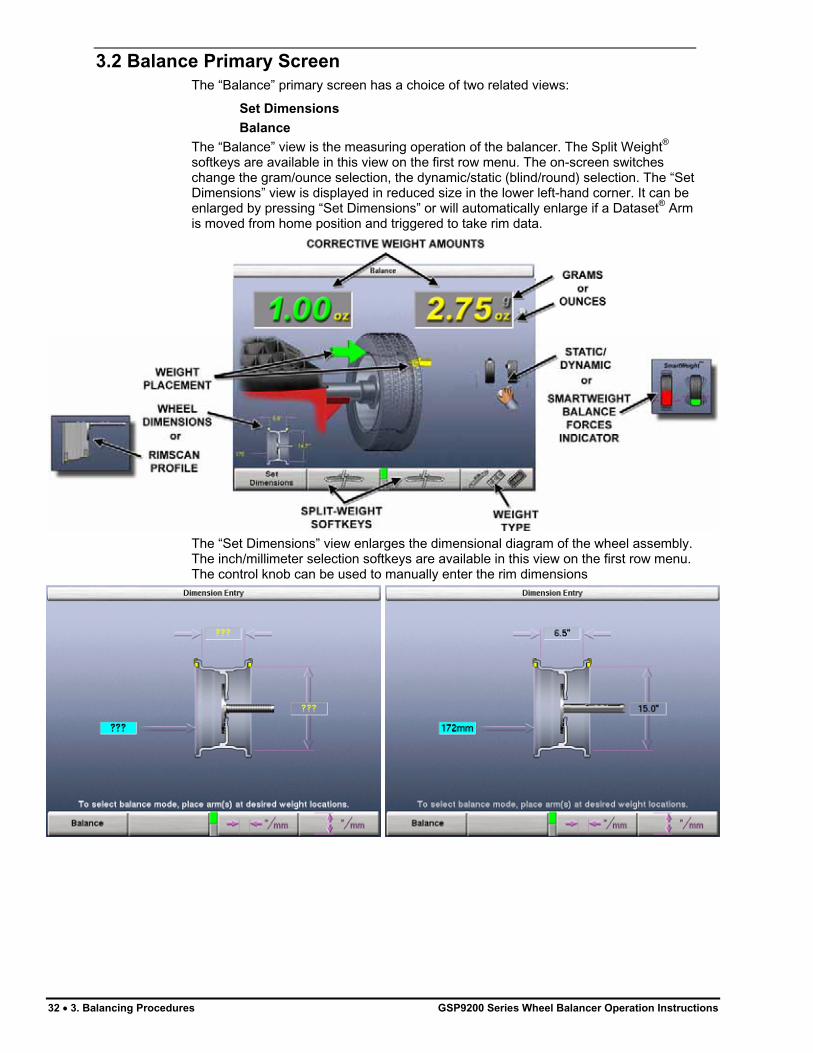
The “Balance” view is the measuring operation of the balancer. The Split Weight®
softkeys are available in this view on the first row menu. The on-screen switches change the gram/ounce selection, the dynamic/static (blind/round) selection. The “Set Dimensions” view is displayed in reduced size in the lower left-hand corner. It can be enlarged by pressing “Set Dimensions” or will automatically enlarge if a Dataset® Arm is moved from home position and triggered to take rim data.
The “Set Dimensions” view enlarges the dimensional diagram of the wheel assembly. The inch/millimeter selection softkeys are available in this view on the first row menu. The control knob can be used to manually enter the rim dimensions
32 � 3. Balancing Procedures GSP9200 Series Wheel Balancer Operation Instructions

3.3 Wheel Assembly Selection for Saving Spin Data
Saving Spin Data
The GSP9720 tracks the wheel assembly currently being balanced.
The balancer assumes that the technician is working “around the vehicle” by beginning at the LEFT FRONT and working around the vehicle in a clockwise fashion. Successive spins are stored as either “before” or “after” data based on the following rules:
� If the weight displays read “OK/OK” or “---/---”, assume the next complete spin is “before” data
� If the weight displays read anything other than “OK/OK” or “---/---”, assume the next complete spin is “after” data
“Prompt for Wheel Assembly ID” can be disabled in setup when “Balance” is selected from the Logo screen.
Storing Measurements
Verify that the wheel is clean and free of debris.
Remove all previous weights.
Mount tire/wheel assembly. Refer to “Mount the Wheel on the Spindle Shaft,” page 25.
Enter the rim dimensions using the Dataset® arms and select “Balance”.
Close safety hood.
Press the green “START” button if “Hood Autostart” is disabled.
Press the “Menu Shift” until the “Store Measurements” selection is available.
Select “Store Measurements”. The measurements are stored for the front left assembly.
Select “Exit” to continue.
Balance assembly and continue to the next assembly. The “Store Measurements” screen will automatically progress to the next assembly in a clockwise direction.
GSP9200 Series Wheel Balancer Operation Instructions 3. Balancing Procedures � 33

Repeat “Store Measurements” until all assemblies are complete.
Select either “Clear Before Measurements” or “Clear After Measurements” to use that data at another wheel position.
To reset all stored measurements, Press the “Menu Shift” until the “Clear Data” selection is available. Select “Clear Data” and “OK” to reset.
Print Summary
A printout is available that incorporates a detailed image of each wheel assembly with the stored measurements. If a measured value is out of tolerance compared to the recalled specification, the value will be printed in red.
Select “Print Summary” to view the before and after results.
Select “Print” to send before and after balance summary results to the printer.
3.4 Balance Modes
Select the correct balance mode for each application using the control knob. Refer to “Using the Control knob,” page 10.
34 � 3. Balancing Procedures GSP9200 Series Wheel Balancer Operation Instructions

SmartWeight® Balancing Technology
SmartWeight® balancing technology is a method of reducing forces on a wheel during balancing. SmartWeight® is not a procedure. Instead, it measures the forces of side-to-side movement and up-and-down shake and computes weight to reduce these forces. This reduces the amount of weight, reduces time, reduces check spins and chasing weights. SmartWeight® saves the shop time and money. Refer to “SmartWeight® Balancing Technology,” page 15.
NOTE: SmartWeight® is the default and preferred method of balancing.
Dynamic Balancing – Traditional Balancing Mode
Dynamic balancing is selected by pointing the indicator to while rotating the control knob. Dynamic will always display two weight planes. Dynamic balancing provides a more complete balance than static balancing. Dynamic balancing should be selected whenever possible to minimize vehicle vibration. Refer to “Balancing Theory-Couple Imbalance,” page 14.
GSP9200 Series Wheel Balancer Operation Instructions 3. Balancing Procedures � 35

Static Balancing – Traditional Balancing Mode
Static balancing is selected by pointing the indicator to while using the control knob. Static balancing provides a less desirable balance than dynamic balancing. Dynamic balancing should be selected whenever possible to minimize vehicle vibration. Refer to “Balancing Theory-Static Imbalance,” page 13.
Static Balance Mode Reminder (Except Patch Balance)
Two reminder pop-up text messages appear on the balance screen dialog box when selecting static mode. The first screen gives the warning: “Avoid STATIC single-plane balancing.”
The second screen suggests: “DYNAMIC dual-plane balancing recommended (even for hidden weights).”
If STATIC is selected, the reminders show up again at the end of the spin.
36 � 3. Balancing Procedures GSP9200 Series Wheel Balancer Operation Instructions

3.5 Balancing Procedures for Specific Weight Types and Placement
Press to change the weight types and placement. The GSP9200 offers Standard Balance, Mixed Weights Balance, Adhesive Weights Balance, and Patch Balance� for dynamic and static modes.
With these four selections, a correction weight can be placed at an infinite number of locations, based upon the choice of the operator.
AUTO MODE DETECTION is the default setting automatically choosing the correct type of weights and locations determined by the placement of the dataset arms.
STANDARD BALANCE should be selected when clip-on weights can be used for both rim flanges.
MIXED WEIGHTS BALANCE should be selected when a clip-on weight can be used on the inner rim flange, but not on the outer rim flange. Mixed Weights Balance uses an adhesive weight for the right weight plane instead of a clip-on weight to avoid marring aluminum rims or to hide weights from view.
ADHESIVE WEIGHTS BALANCE should be selected when clip-on weights cannot be used on either rim flange.
PATCH BALANCE should be selected when the tire has a very large imbalance in the tire assembly. The large imbalance can be corrected with Patch Balancing and then the assembly can be fine-tuned with one of the other balancing procedures.
AUTO MODE Balancing Using All Weight Types and Locations
Selecting AUTO MODE will choose the correct weight type and placement for the specific wheel. AUTO MODE incorporates procedures of specific wheel balance methods as outlined on the following pages.
GSP9200 Series Wheel Balancer Operation Instructions 3. Balancing Procedures � 37

STANDARD Balancing Procedure Using Clip-On Weights
There are many types of clip-on weights. Determine the correct application before installing weights.
Verify that the wheel is clean and free of debris.
Remove all previous weights.
Mount tire/wheel assembly. Refer to “Mounting the Wheel on the Spindle Shaft,” page 25.
Press . Use the softkey arrows to select “STANDARD BALANCE” and press “OK.”
Select either grams or ounces by rotating the control knob and highlighting either “g” or “oz.”
Select “DYNAMIC” by rotating the control knob to highlight “ .” Refer to “Dynamic Balancing Selection,” page 35.
Use both Dataset® arms in the UPWARD position at the clip-on weight location to measure the distance, diameter, and rim width dimensions. Refer to “Automatic Dataset® Arms Operation,” page 46.
NOTE: The Dataset® Arms should be positioned in the location for weight placement. Refer to “Measuring Dimensions for Standard Clip-on Weight Balancing,” page 48.
Enter the data by depressing the foot pedal. Release the Dataset® arms.
Close safety hood.
Press the green “START” button if “Hood Autostart” is disabled.
After wheel comes to a complete stop, raise the safety hood.
The GSP9200 will find the TDC for the left weight plane if “Servo-Stop” is enabled. “Servo-Stop” will hold the wheel in the TDC position while the weight is applied. The weight amount will be displayed in green.
38 � 3. Balancing Procedures GSP9200 Series Wheel Balancer Operation Instructions
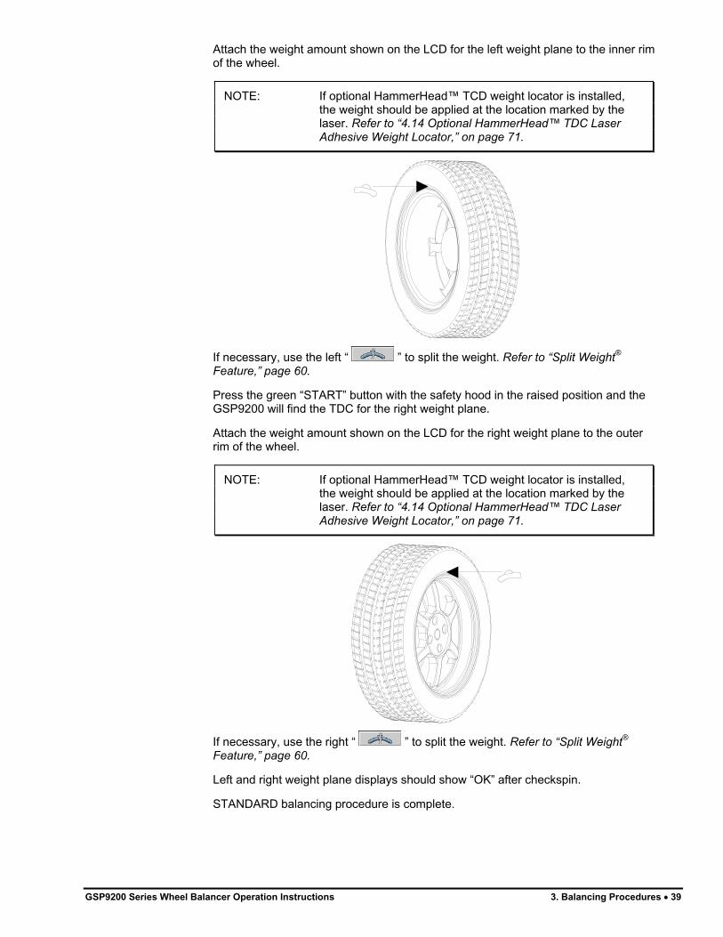
Attach the weight amount shown on the LCD for the left weight plane to the inner rim of the wheel.
NOTE: If optional HammerHead™ TCD weight locator is installed, the weight should be applied at the location marked by the laser. Refer to “4.14 Optional HammerHead™ TDC Laser Adhesive Weight Locator,” on page 71.
If necessary, use the left “ ” to split the weight. Refer to “Split Weight®
Feature,” page 60.
Press the green “START” button with the safety hood in the raised position and the GSP9200 will find the TDC for the right weight plane.
Attach the weight amount shown on the LCD for the right weight plane to the outer rim of the wheel.
NOTE: If optional HammerHead™ TCD weight locator is installed, the weight should be applied at the location marked by the laser. Refer to “4.14 Optional HammerHead™ TDC Laser Adhesive Weight Locator,” on page 71.
If necessary, use the right “ ” to split the weight. Refer to “Split Weight®
Feature,” page 60.
Left and right weight plane displays should show “OK” after checkspin.
STANDARD balancing procedure is complete.
GSP9200 Series Wheel Balancer Operation Instructions 3. Balancing Procedures � 39

MIXED WEIGHTS Balancing Procedure
Using a Combination of Clip-On & Adhesive Weights
Verify that the wheel is clean and free of debris.
Remove all previous weights.
Mount tire/wheel assembly. Refer to “Mounting the Wheel on the Spindle Shaft,” page 25.
Press . Use the arrows to select “MIXED WEIGHTS BALANCE” and press “OK.”
Select either grams or ounces by rotating the control knob and highlighting either “g” or “oz.”
Select “DYNAMIC” by rotating the control knob to highlight “ ,” if SmartWeight® is enabled. Refer to “Dynamic Balancing,” page 35.
Use inner Dataset® arm in the UPWARD position at the clip-on weight location to measure the distance, diameter, and rim width dimensions. Refer to “Using the Auto Dataset® Arms,” page 46.
Do NOT return the arm to the “home” position.
Using the DOWNWARD position, move the inner Dataset® arm disk edge to the location for placement of the right edge of the adhesive weight on the right weight plane and enter data by depressing the foot pedal. Refer to “Automatic Dataset® Arms Operation,” page 46.
Close safety hood.
Press the green “START” button if “Hood Autostart” is disabled.
After wheel comes to a complete stop, raise safety hood.
The GSP9200 will find the TDC for the left weight plane if “Servo-Stop” is enabled. “Servo-Stop” will hold the wheel in the TDC position while the weight is applied.
40 � 3. Balancing Procedures GSP9200 Series Wheel Balancer Operation Instructions
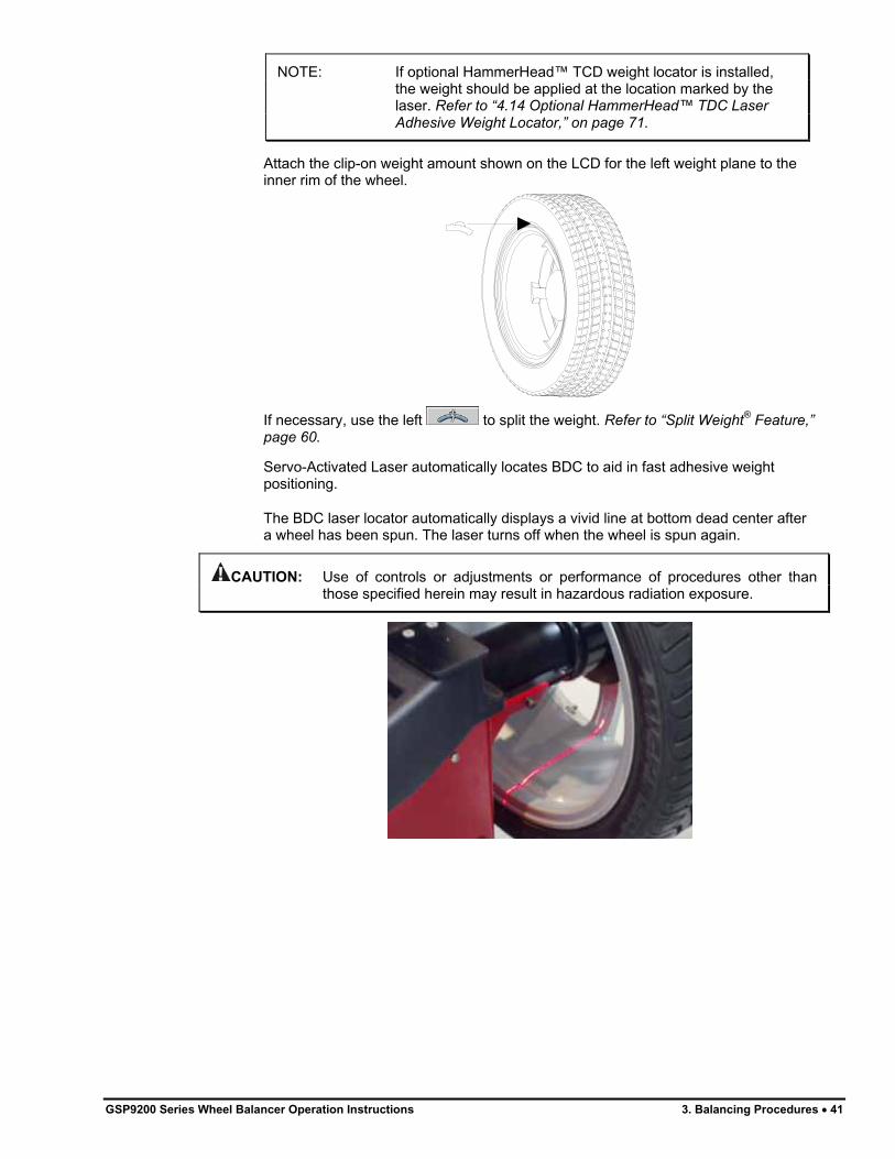
NOTE: If optional HammerHead™ TCD weight locator is installed, the weight should be applied at the location marked by the laser. Refer to “4.14 Optional HammerHead™ TDC Laser Adhesive Weight Locator,” on page 71.
Attach the clip-on weight amount shown on the LCD for the left weight plane to the inner rim of the wheel.
If necessary, use the left to split the weight. Refer to “Split Weight® Feature,” page 60.
Servo-Activated Laser automatically locates BDC to aid in fast adhesive weight positioning.
The BDC laser locator automatically displays a vivid line at bottom dead center after a wheel has been spun. The laser turns off when the wheel is spun again.
CAUTION: Use of controls or adjustments or performance of procedures other than those specified herein may result in hazardous radiation exposure.
GSP9200 Series Wheel Balancer Operation Instructions 3. Balancing Procedures � 41

With the servo enabled, attach the adhesive weight using the weight amount shown for the right weight plane on the LCD. Refer to “Servo-Aided Adhesive Weight Placement,” page 49. If servo is not enabled, BDC placement should be used. Referto “Manual Weight Position Measurement,” page 47.
If necessary, use the right “ ” to split the weight. Refer to “Split Weight®
Feature,” page 60.
Left and right weight plane displays should show “OK,” after checkspin.
MIXED WEIGHTS balancing procedure is complete.
ADHESIVE WEIGHTS Balancing Procedure Using Adhesive Weights
Verify that the wheel is clean and free of debris.
Remove all previous weights.
Mount tire/wheel assembly. Refer to “Mount the Wheel on the Spindle Shaft,” page 25.
Press . Use the arrows to select “ADHESIVE WEIGHTS BALANCE” and press “OK.”
Select either grams or ounces by rotating the control knob and highlighting either “g” or “oz.”
Select “DYNAMIC” by rotating the control knob to highlight “ .” Refer to “Dynamic Balancing,” page 35, if SmartWeight® is enabled.
42 � 3. Balancing Procedures GSP9200 Series Wheel Balancer Operation Instructions
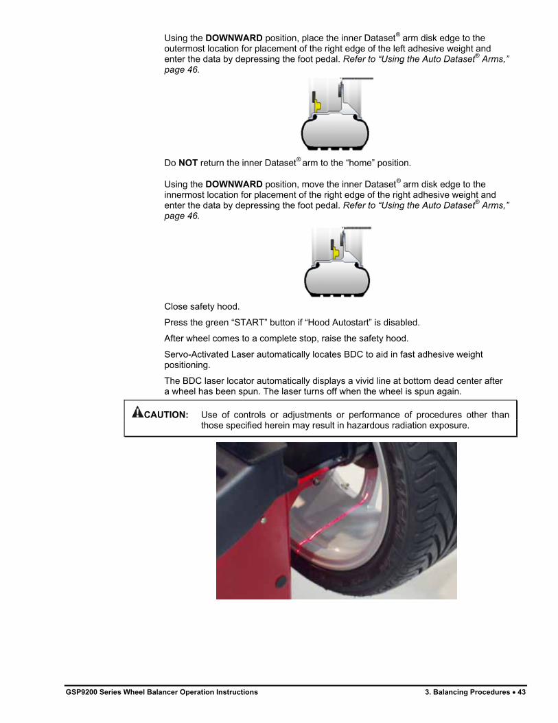
Using the DOWNWARD position, place the inner Dataset® arm disk edge to the outermost location for placement of the right edge of the left adhesive weight and enter the data by depressing the foot pedal. Refer to “Using the Auto Dataset® Arms,” page 46.
Do NOT return the inner Dataset® arm to the “home” position.
Using the DOWNWARD position, move the inner Dataset® arm disk edge to the innermost location for placement of the right edge of the right adhesive weight and enter the data by depressing the foot pedal. Refer to “Using the Auto Dataset® Arms,” page 46.
Close safety hood.
Press the green “START” button if “Hood Autostart” is disabled.
After wheel comes to a complete stop, raise the safety hood.
Servo-Activated Laser automatically locates BDC to aid in fast adhesive weight positioning.
The BDC laser locator automatically displays a vivid line at bottom dead center after a wheel has been spun. The laser turns off when the wheel is spun again.
CAUTION: Use of controls or adjustments or performance of procedures other than those specified herein may result in hazardous radiation exposure.
GSP9200 Series Wheel Balancer Operation Instructions 3. Balancing Procedures � 43

With the servo enabled, attach the adhesive weight for the left weight plane using the weight amount shown on the LCD. Refer to “Servo-Aided Adhesive Weight Placement,” page 49. If servo is not enabled, BDC placement should be used. Referto “Manual Weight Position Measurement,” page 47.
If necessary, use the left to split the weight. Refer to “Split Weight® Feature,” page 60.
Return the inner Dataset® arm to the home position.
With the servo enabled, attach the adhesive weight for the right weight plane using the weight amount shown on the LCD. Refer to “Servo-Aided Adhesive Weight Placement,” page 49. If servo is not enabled, BDC placement should be used. Refer to “Manual Weight Position Measurement,” page 47.
If necessary, use the right to split the weight. Refer to “Split Weight®
Feature,” page 60.
Left and right weight plane displays should show “OK,” after checkspin.
ADHESIVE WEIGHTS balancing procedure is complete.
PATCH BALANCE® Procedure
Weighted balance patches will be placed on the inside of the tire at the edge of the tread area beside the sidewall as shown below:
LEFT PLANE
RIGHT PLANE
INTERNAL DIAMETER
44 � 3. Balancing Procedures GSP9200 Series Wheel Balancer Operation Instructions

NOTE: Weighted balance patches should be installed only in tread area. Do not install weighted balance patches near sidewall or shoulder of tire.
Verify that the wheel is clean and free of debris.
Remove all previous weights.
Mount tire/wheel assembly. Refer to “Mount the Wheel on the Spindle Shaft,” page 25.
Press . Use the arrows to select “PATCH BALANCE” and press “OK.”
Select either grams or ounces by rotating the control knob and highlighting either “g” or “oz.”
Select “DYNAMIC” by rotating the control knob to highlight “ .” Refer to “Dynamic Balancing,” page 35, if SmartWeight® is enabled.
NOTE: When measuring large tires that will use balance patches, it may require removal of the outer arm “home position” bumper for ample clearance of the outer Dataset® arm. The bumper can be removed by loosening three Phillips head screws and gently pulling the bumper away from the arm.
PHILLIPS HEAD
SCREW PHILLIPS HEAD
SCREW
PHILLIPS HEAD
SCREW BUMPER
Measure and enter the weight plane distances as follows:
Set two of the widest weighted balance patches available side-by-side on the tread directly above where the left and right weighted patches will be installed inside of the tire. The patches should be positioned as far apart from each other as possible, but should not be placed in the sidewall or shoulder area of the tire. Mark the tire tread at the center of the patches for future placement reference and remove the patches from the wheel. Place outer Dataset® arm roller directly over the left mark and enter data by depressing the foot pedal.
GSP9200 Series Wheel Balancer Operation Instructions 3. Balancing Procedures � 45

Place outer Dataset® arm roller directly over the right mark and enter data by depressing the foot pedal.
Close safety hood.
Press the green “START” button if “Hood Autostart” is disabled.
After wheel stops spinning, raise the safety hood.
Press the green “START” button with the safety hood in the RAISED position and the GSP9200 will find TDC for the left weight plane. Mark the tire’s inner sidewall for patch placement.
Press the green “START” button with the safety hood in the RAISED position and the GSP9200 will find TDC for the right weight plane. Mark the tire’s outer sidewall for patch placement.
Place an aligning mark on the tire and rim to align them back together after applying the patch weights.
Remove wheel from balancer and dismount tire from rim.
Install left weight plane weighted balance patch(s) at mark(s) as instructed by manufacturer's instructions.
Install right weight plane weighted balance patch(s) at mark(s) as instructed by manufacturer's instructions.
Mount tire onto rim, aligning rim and tire marks.
Finish the patch balancing procedure by returning to the appropriate balance procedure for the type of wheel being balanced. Verify balance condition by spinning again, and attach weights as necessary to correct for residual imbalance.
PATCH balancing procedure is complete.
3.6 Automatic Dataset® Arms Operation
Auto Dataset® arms are a faster and more accurate method to take rim measurements than traditional methods. Auto Dataset® arms are used to input rim distance, rim width, weight plane location, and weight position measurements automatically. The Dataset® Arms of the GSP9200 are positioned on the weight plane and data is entered by depressing the foot pedal.
46 � 3. Balancing Procedures GSP9200 Series Wheel Balancer Operation Instructions

Automatic Weight Position Measurement
The Dataset® arms can be used to enter weight position dimensions instantly and accurately. The arms are “triggered” when they are moved away from their home position. When the arms are triggered, a blinking graphic depicting the Dataset® arm on the “Dimension Entry” screen identifies the plane currently being inputted.
In most cases, the Dataset® Arms are used to input the exact weight position.
The exact weight position is entered by holding the arm(s) stable in the desired location and depressing the foot pedal to enter the dimensional data.
Manual Weight Position Measurement
NOTE: If optional HammerHead™ TCD weight locator is installed, the weight should be applied at the location marked by the laser. Refer to “4.14 Optional HammerHead™ TDC Laser Adhesive Weight Locator,” on page 71.
While on the “Set Dimensions” view of the “Balance” primary screen, the control knob can be used to enter rim dimensions manually.
Hunter Engineering Company recommends using the inner and outer Dataset® arms to enter dimensions. Refer to “Using the Auto Dataset® Arms,” page 46.
GSP9200 Series Wheel Balancer Operation Instructions 3. Balancing Procedures � 47

Measuring Dimensions for Standard Clip-on Weight Balancing
To measure rim dimensions for clip-on weights, pull the inner Dataset® arm away from the weight tray and UPWARD until it is touching the top of the wheel inner rim lip. Simultaneously pull the outer Dataset® arm out and upward until it is touching the top of the wheel outer rim lip. While the Dataset® arms are in place, depress the foot pedal to enter the dimensional data. The GSP9200 will beep to confirm data entry.
NOTE: Dataset® arms can input dimensions separately if desired.
Measuring Dimensions for Mixed Weights (Clip-on/Adhesive) Balance
To measure rim dimensions for the clip-on weight, pull the inner Dataset® arm away from the weight tray and UPWARD until it is touching the wheel inner rim lip. Depress the foot pedal to enter the dimensional data. The GSP9200 will beep to confirm data entry.
Do NOT return the Dataset® arm to the home position. Move the Dataset® arm DOWNWARD until the roller disk edge is touching the wheel at the right edge of the desired adhesive weight location. Depress the foot pedal to enter the dimensional data. The GSP9200 will beep to confirm data entry.
48 � 3. Balancing Procedures GSP9200 Series Wheel Balancer Operation Instructions
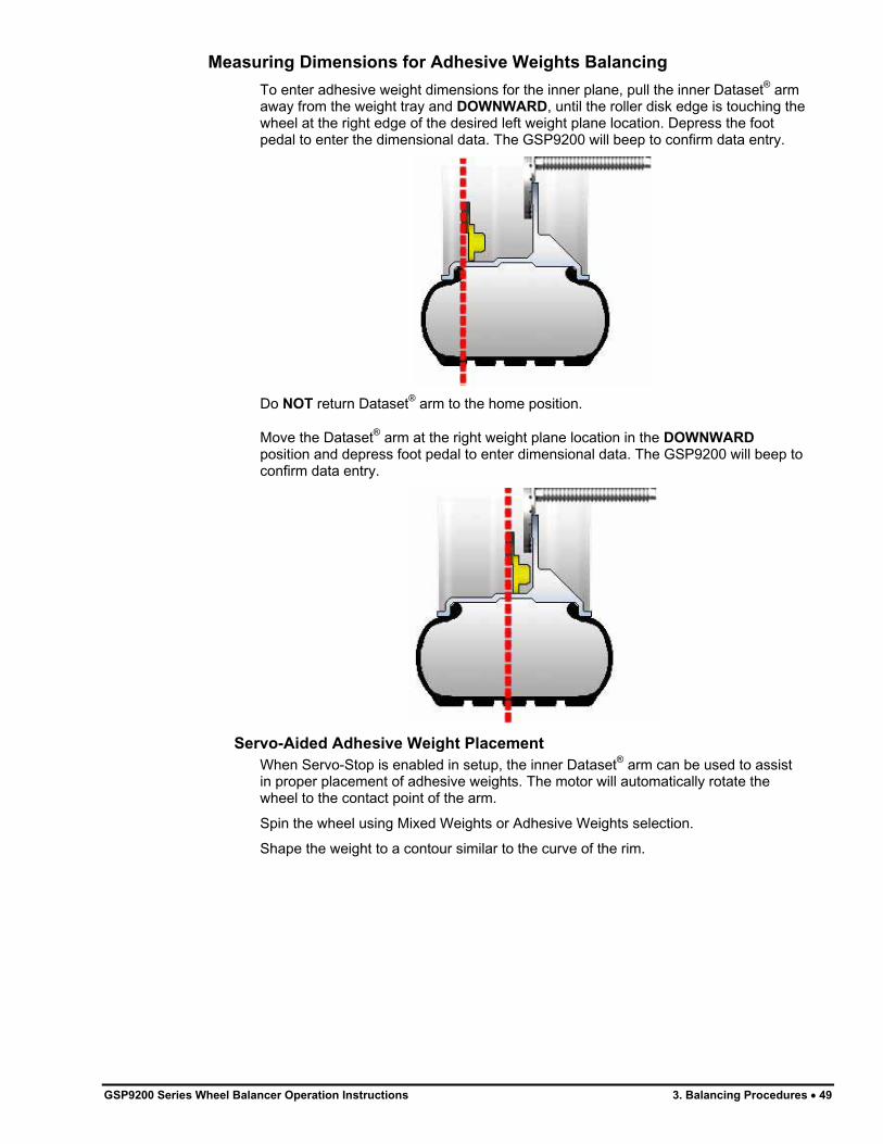
Measuring Dimensions for Adhesive Weights Balancing
To enter adhesive weight dimensions for the inner plane, pull the inner Dataset® arm away from the weight tray and DOWNWARD, until the roller disk edge is touching the wheel at the right edge of the desired left weight plane location. Depress the foot pedal to enter the dimensional data. The GSP9200 will beep to confirm data entry.
Do NOT return Dataset® arm to the home position.
Move the Dataset® arm at the right weight plane location in the DOWNWARD
position and depress foot pedal to enter dimensional data. The GSP9200 will beep to confirm data entry.
Servo-Aided Adhesive Weight Placement
When Servo-Stop is enabled in setup, the inner Dataset® arm can be used to assist in proper placement of adhesive weights. The motor will automatically rotate the wheel to the contact point of the arm.
Spin the wheel using Mixed Weights or Adhesive Weights selection.
Shape the weight to a contour similar to the curve of the rim.
GSP9200 Series Wheel Balancer Operation Instructions 3. Balancing Procedures � 49
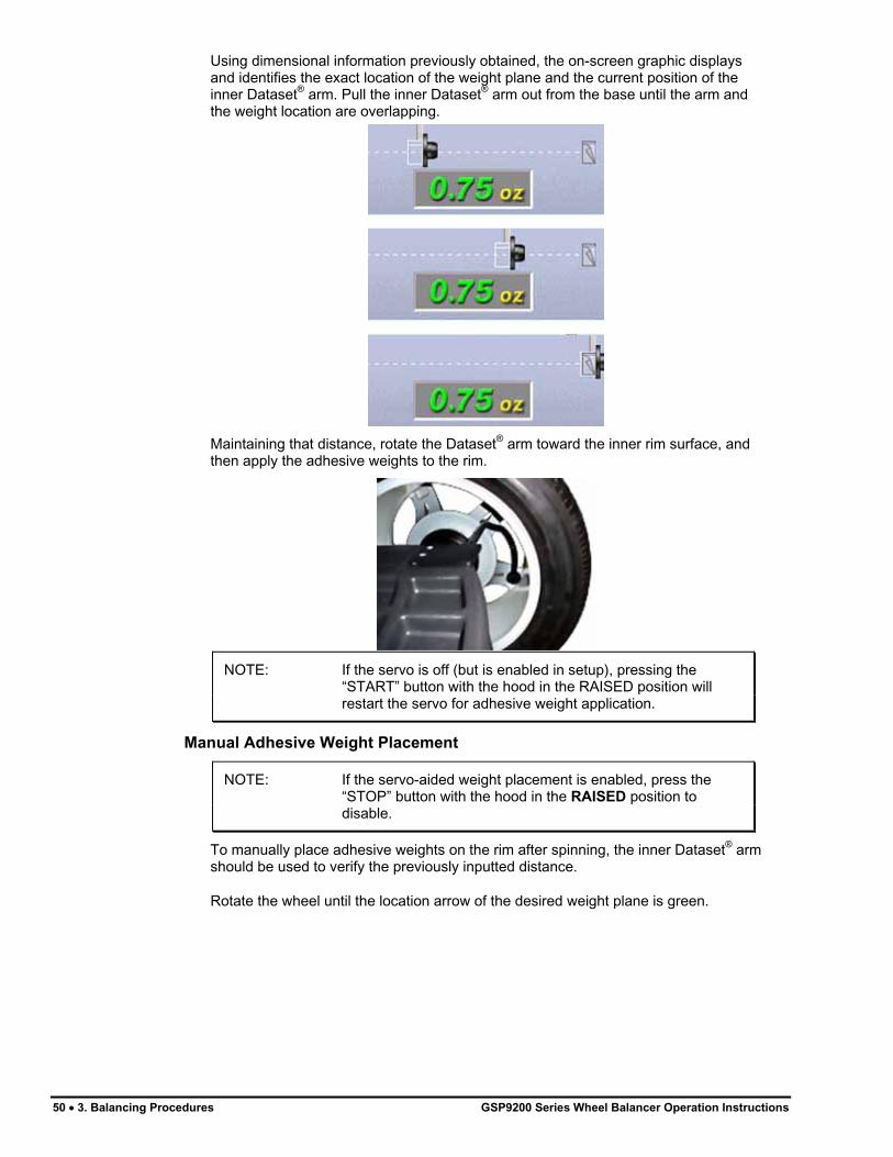
Using dimensional information previously obtained, the on-screen graphic displays and identifies the exact location of the weight plane and the current position of the inner Dataset® arm. Pull the inner Dataset® arm out from the base until the arm and the weight location are overlapping.
Maintaining that distance, rotate the Dataset® arm toward the inner rim surface, and then apply the adhesive weights to the rim.
NOTE: If the servo is off (but is enabled in setup), pressing the “START” button with the hood in the RAISED position will restart the servo for adhesive weight application.
Manual Adhesive Weight Placement
NOTE: If the servo-aided weight placement is enabled, press the “STOP” button with the hood in the RAISED position to disable.
To manually place adhesive weights on the rim after spinning, the inner Dataset® arm should be used to verify the previously inputted distance.
Rotate the wheel until the location arrow of the desired weight plane is green.
50 � 3. Balancing Procedures GSP9200 Series Wheel Balancer Operation Instructions

Lift the inner Dataset® arm from home position. The “real-time” number displayed between the two numbers that represent previously inputted data displays the current reading of the inner Dataset® arm. The arm should be placed in the downward position on the rim until the real-time number matches the previously inputted data.
NOTE: Lifting the inner Dataset® arm will trigger the balancer for dimension input. Do NOT step on the foot pedal or new dimensions will be entered.
The BDC laser locator automatically displays a vivid line at bottom dead center after a wheel has been spun. The laser turns off when the wheel is spun again.
The weight should be placed at BDC at that distance.
CenteringCheck®
Wheel Centering Feature
Using Imbalance Forces and Location
The CenteringCheck® feature can be used to inspect each mounting to identify possible centering errors, thus preventing improper measurements from occurring.
CenteringCheck® may be used with either a “bare rim” or a “rim with tire assembly.” On-screen prompts lead you through the procedure. Select “Perform Centering Check” from the menu.
GSP9200 Series Wheel Balancer Operation Instructions 3. Balancing Procedures � 51

Follow the on-screen prompts.
Position the valve stem at 12 o’clock, and then press “Enter Valve Stem.”
After entering the valve stem position, you will be prompted to loosen the wheel and re-clamp at one half turn (approximately 180 degrees) from the current position.
Press “Start” when ready to take readings.
52 � 3. Balancing Procedures GSP9200 Series Wheel Balancer Operation Instructions

Once more, position the valve stem at 12 o’clock, and then press “Enter Valve Stem.” If the rim is centered properly, the following screen will appear briefly.
The GSP9200 will then proceed to the “Balance” screen.
If a centering problem is detected, the following screen will appear.
The procedure will repeat the re-centering check up to four times and always compare the previous measurement to the next check. If centering is not achieved after four attempts, the following screen will appear.
Check for: Correct mounting cone/adaptor for this wheel design.
GSP9200 Series Wheel Balancer Operation Instructions 3. Balancing Procedures � 53

54 � 3. Balancing Procedures GSP9200 Series Wheel Balancer Operation Instructions
Wheel defect such as a metal burr interfering with the cone/adaptor. Dirt or debris interfering with the cone/adaptor.
Follow the on-screen prompts, and then press “Restart Procedure.”

4. Balancing Features and Options
4.1 Blinding and Rounding
In non-SmartWeight® mode the balancer can display either an “actual” or “blinded and rounded” amount of imbalance.
“Blind” is a tolerance or amount of imbalance required before an imbalance amount is displayed. “Round” allows the balancer to display weight imbalance to a desired increment. The blind and round values can be changed in the “Setup” procedure. Refer to “Service Mode Setup and Features,” page 76.
While in the “Balance” primary screen, blind and rounding may be disabled by
rotating the control knob to highlight . The actual amounts of imbalance for the selected mode will be displayed when “Blind and Rounding” are disabled as shown below.
4.2 TPMSpecs TM
Feature
NOTE: TPMS specifications can also be found on Hunter Aligners (with WinAlign 11.0) and online at UnderCarInfo.NET (subscription service).
The TPMSpecs feature identifies vehicles with tire pressure monitoring systems. It also provides in-depth information regarding the service of TPMS.
� TPMS Type
� Sensor Type
� Reset Required on Tire Rotation or Replacement
� Reset Tool Requirement
� Required Tools
� Reset Procedure
� TPMS Hints
� Information / Disclaimers
GSP9200 Series Wheel Balancer Operation Instructions 4. Balancing Features and Options � 55

TPMSpecs may be accessed in two ways.
Option 1:
From the main balance screen, scan a VIN barcode. TPMS information for the vehicle scanned will automatically be retrieve and display.
Option 2:
From the main balance screen, press the menu key to shift down the softkey rows until “Recall TPMS Info” softkey appears. Press “Recall TPMS Info” softkey and then select appropriate vehicle from the drop down menu, using the control knob or softkeys.
TPMSpecs screens to displays detailed TPMS service information for the vehicle.
The “AT A GLANCE” overview starts each vehicle TPMS specification. The first image shows the type of TPMS sensor on the vehicle. The following three images show the requirements for servicing the wheel: process, scan tool and OEM scanner. The red border, yellow border or grayed appearance of the image denotes the requirement as required, optional or not required. Red and white striped border (as in above TPMSpecs screen) indicates the requirement is possibly required; refer to the explanation below the images.
Scroll down by turning the control knob for detail TPMS information for the vehicle.
4.3 Hunter Help Feature
The Hunter Help feature (version 3.1 software or higher required for Hunter Help Files) provides tips and procedures for Hunter balancers and tire changers. It also provides a Rolling Smooth Sample Quiz.
Additional content will be added to the Hunter Help files and can be updated as new content becomes available.
56 � 4. Balancing Features and Options GSP9200 Series Wheel Balancer Operation Instructions
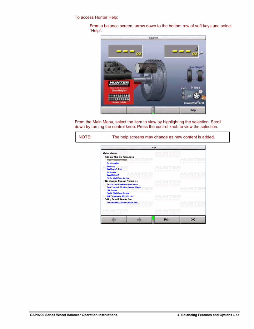
To access Hunter Help:
From a balance screen, arrow down to the bottom row of soft keys and select “Help”.
From the Main Menu, select the item to view by highlighting the selection. Scroll down by turning the control knob. Press the control knob to view the selection.
NOTE: The help screens may change as new content is added.
GSP9200 Series Wheel Balancer Operation Instructions 4. Balancing Features and Options � 57
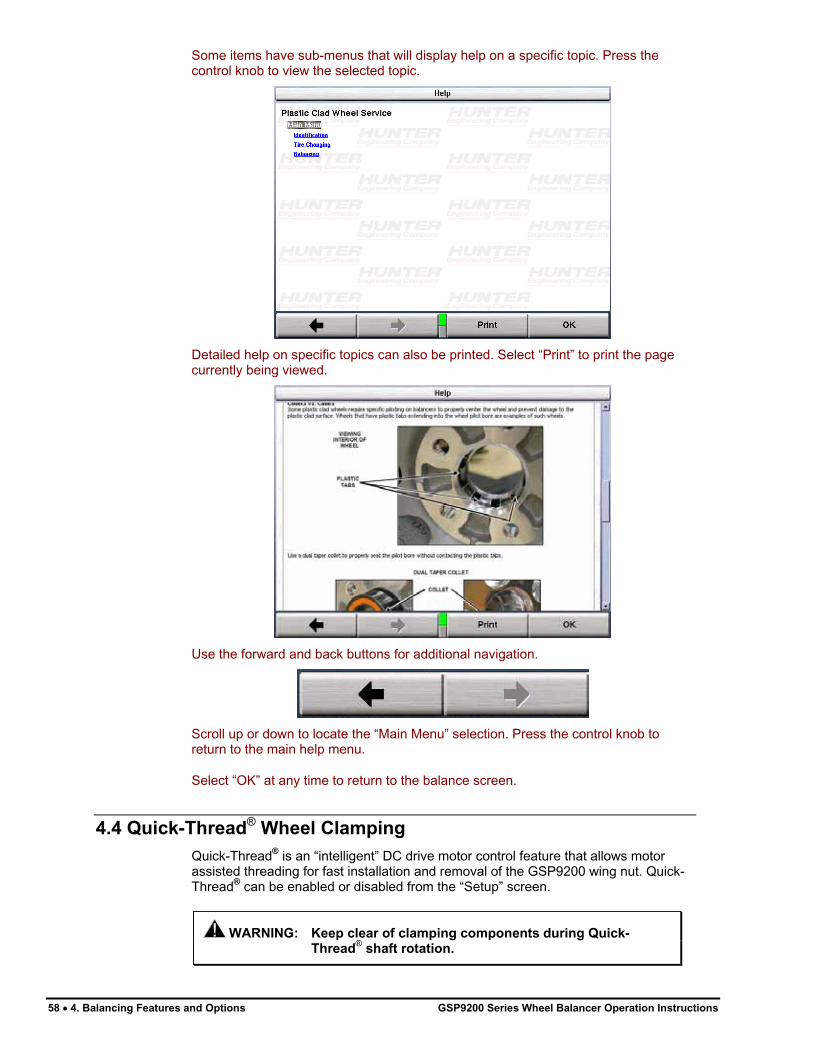
Some items have sub-menus that will display help on a specific topic. Press the control knob to view the selected topic.
Detailed help on specific topics can also be printed. Select “Print” to print the page currently being viewed.
Use the forward and back buttons for additional navigation.
Scroll up or down to locate the “Main Menu” selection. Press the control knob to return to the main help menu.
Select “OK” at any time to return to the balance screen.
4.4 Quick-Thread® Wheel Clamping
Quick-Thread® is an “intelligent” DC drive motor control feature that allows motor assisted threading for fast installation and removal of the GSP9200 wing nut. Quick-Thread® can be enabled or disabled from the “Setup” screen.
WARNING: Keep clear of clamping components during Quick-
Thread® shaft rotation.
58 � 4. Balancing Features and Options GSP9200 Series Wheel Balancer Operation Instructions

Lift the wheel assembly onto the shaft as normal without threading on the wing nut.
With the left hand, hold the rim over the cone to remove the weight of the rim from the spindle and to allow maximum Quick-Thread® wing nut travel.
Place the wing nut on the spindle and rotate one full turn onto the spindle threads.
With the right hand, hold one handle of the wing nut while lifting the rim.
NOTE: Heavier wheel assemblies may require extra lifting to prevent the software limited motor torque control from stopping the rotation of the spindle.
Tap the foot pedal twice and the spindle will rotate to install the wing nut to save threading time.
The direction of spindle rotation toggles each time it is used. For normal operation, spindle rotation will begin in the correct direction for wing nut installation. A single tap within the first three seconds of rotation will reverse the direction of rotation. A single tap after the first three seconds of rotation will stop rotation.
Quick-Thread® spindle rotation will stop when the clamping components contact the wheel, or when the foot brake is applied for more than half of a second.
CAUTION: Quick-Thread® does not tighten the wing nut! In Quick-Thread® rotation, torque allowed is minimal. Therefore, the wing nut must still be hand-tightened before balancing.
NOTE: Also because of the software limited torque control, you must loosen the wing nut before Quick-Thread® will remove it.
Quick-Thread® will not operate under the following conditions: If the balancer is in “Diagnostics,” “Setup,” or any calibration procedures except “Servo-Stop.” If either Dataset® arm is out of its “home position” while in the “Balance.”
4.5 Auto-Clamp™ Wheel Clamping (Optional)
Auto-Clamp™ is an optional spindle equipped with a pneumatic clamping device that eliminates the spin on type wingnut.
Refer to page 26, for detailed operation instructions.
4.6 Motor Drive/Servo-Stop
The intelligent DC motor drive on the GSP9200 is able to position and hold the tire assembly in position for weight application, apply different amounts of torque, and control the speed and direction of the spindle.
If Servo-Stop is enabled, when the “Start” button is pushed with the hood in the raised position, while weights are showing, the motor will automatically rotate the wheel to the next weight plane and hold the assembly in position for weight or mark application.
GSP9200 Series Wheel Balancer Operation Instructions 4. Balancing Features and Options � 59

Servo-Stop can be enabled or disabled from the “Set Up” primary screen. Refer to “Servo-Stop,” page 76.
4.7 Spindle-Lok® Feature
Depressing the foot pedal will lock the spindle. Locking the spindle will stabilize the wheel for attaching weights at precise locations if automatic weight positioning is disabled, and will allow for tightening and loosening of the wing nut. Do not use the Spindle-Lok® as a brake to stop a spinning wheel.
NOTE: Depressing the foot pedal will cancel Servo-Stop.
CAUTION: Using the Spindle-Lok® to stop a spinning wheel may result in personal injury or damage to the balancer.
4.8 Hood Autostart Feature
The balancer can be set to automatically spin the wheel upon hood closure. After a spin, the hood must be lifted completely before the balancer will Autostart again.
For safety, the balancer will not Autostart in “Calibration,” “Setup,” “Diagnostics,” if no balancing procedure is selected, or if the Inflation Station hose is out of its “home position.”
The hood close Autostart feature can be enabled or disabled in the “Setup” procedure. Refer to “Setting Up the Hood Autostart Feature,” page 76.
4.9 Loose Hub Detect Feature
When the GSP9200 senses that the wheel is loose, it will automatically stop the spin. You should tighten the wing nut before proceeding.
NOTE: If the wing nut appears to be tight, remove the wing nut and then clean and lubricate the spindle threads. Refer to “Spindle Hub Face and Shaft Maintenance,” page 95.
4.10 Split Weight® Feature
Press to change the required imbalance correction weight amount into two smaller size weights. The angle is adjusted by the balancer to produce the non-rounded correction called for by the single weight before split. This provides exact imbalance correction without weight trimming. The non-rounded imbalance is split regardless of whether blind and rounding are enabled. For this reason, Split Weight®
is more accurate than applying a single weight with the blind and rounding enabled.
Split Weight® is especially useful when the imbalance amount is large or unavailable, such as 6.0 ounces. Split Weight® eliminates the error caused by placing two 3.0 ounce weights side-by-side, which would leave a substantial residual imbalance:
60 � 4. Balancing Features and Options GSP9200 Series Wheel Balancer Operation Instructions

Use when the weight location interferes with a hubcap or trim ring, when one weight is too large, to avoid weight trimming, or to substitute for a weight size that is out of stock.
Split Weight® Operation
Each time is pressed, the two weights are increased to the next largest weight size and are placed (fanned out) further down the rim, as shown below.
NOTE: To return to the original single weight, you can either toggle the control knob between static and dynamic, or continue to split the weight until all choices are exhausted.
Press the green “START” button with the safety hood in the RAISED position and the GSP9200 will find the first split weight plane.
Attach the appropriate weight as displayed on the console.
Continue pressing “START” with the safety hood in the RAISED position and attaching the weights until all weights shown on the console have been applied.
Correcting Large Imbalances
Split Weight® can also be used to apply three weights when needed. For example, a large wheel may require 6.75 ounces. Not only is this size unlikely to be in the weight tray, but splitting 6.75 ounces would likewise result in large weights. In this case, apply one-third of the called for weight (in this case 2.25 ounces) at the 6.75 ounce weight location and spin the assembly again. The display will now call for a 4.5 ounce weight to be placed on top of the 2.25 ounce weight.
6.75 oz
REQUIREDSINGLE WEIGHT
(3) WEIGHTSEQUIVALENT TO 6.75 OZ
2.75 oz 2.75 oz
2.25 oz
GSP9200 Series Wheel Balancer Operation Instructions 4. Balancing Features and Options � 61

Press to fan out the two weights until they clear the previously applied 2.25 ounce weight. Then place the two indicated ounce weights on either side of the 2.25 ounce weight using the TDC indicators.
NOTE: If optional HammerHead™ TCD weight locator is installed, the weight should be applied at the location marked by the laser. Refer to “4.14 Optional HammerHead™ TDC Laser Adhesive Weight Locator,” on page 71.
Another method to correct large imbalances may be achieved with Patch Balancing. Refer to “Patch Balance Procedure,” page 44.
4.11 Split Spoke® Feature
When in either mixed weight or adhesive weight modes, (dynamic or static), correction weights can be hidden behind the spokes of a wheel. The example below is in the mixed weight mode.
Hiding Adhesive Weight behind Spoke Move the inner Dataset® arm to left weight plane position. Enter the data by pressing the foot pedal. Move the inner Dataset® arm to the far right weight position, using the DOWNWARD
arm position. Enter the data by pressing the foot pedal.
After inputting weight plane(s), the Split Spoke® feature may be initiated by the following steps before returning the arm to the “home” position:
Move the inner Dataset� arm to a position centered behind a spoke, using the DOWNWARD arm position. Enter the data by pressing the foot pedal.
NOTE: Split Spoke is also available with RimScan™.
Rotate the wheel to position the Dataset® arm behind an adjacent spoke (nearest spoke in either direction). Enter the data by pressing the foot pedal.
62 � 4. Balancing Features and Options GSP9200 Series Wheel Balancer Operation Instructions

Return the inner Dataset® arm to the home position.
Close safety hood.
Press the green “START” button if “Hood Autostart” is disabled.
After wheel comes to a complete stop, raise safety hood.
Place left plane weight (if in DYNAMIC mode) per the balance procedure being performed. Refer to “Balancing Procedures,” page 25.
Press the green “START” button with the safety hood in the RAISED position and the GSP9200 will servo to the location for the right adhesive weight plane (dynamic) or the static adhesive weight plane (static), aligned with the first spoke.
With the servo enabled, attach the adhesive weight behind the first spoke using the weight amount shown on the LCD. Refer to “Servo-Aided Adhesive Weight Placement,” page 49.
Press the green “START” button with the safety hood in the RAISED position and the GSP9200 will servo to the location for the second spoke.
Attach the appropriate weight as displayed on the console.
All weight plane displays should show “OK,” after checkspin.
SPLIT SPOKE® balancing procedure is complete.
NOTE: When SmartWeight® is enabled in conjunction with wheel spoke entry, a separate feature called “SmartSpoke” can in many instances allow the use of weight at only one spoke when it would have required two using conventional spoke mode balancing. When this occurs, “SmartSpoke” flashes for a few seconds just under the right weight digit.
GSP9200 Series Wheel Balancer Operation Instructions 4. Balancing Features and Options � 63
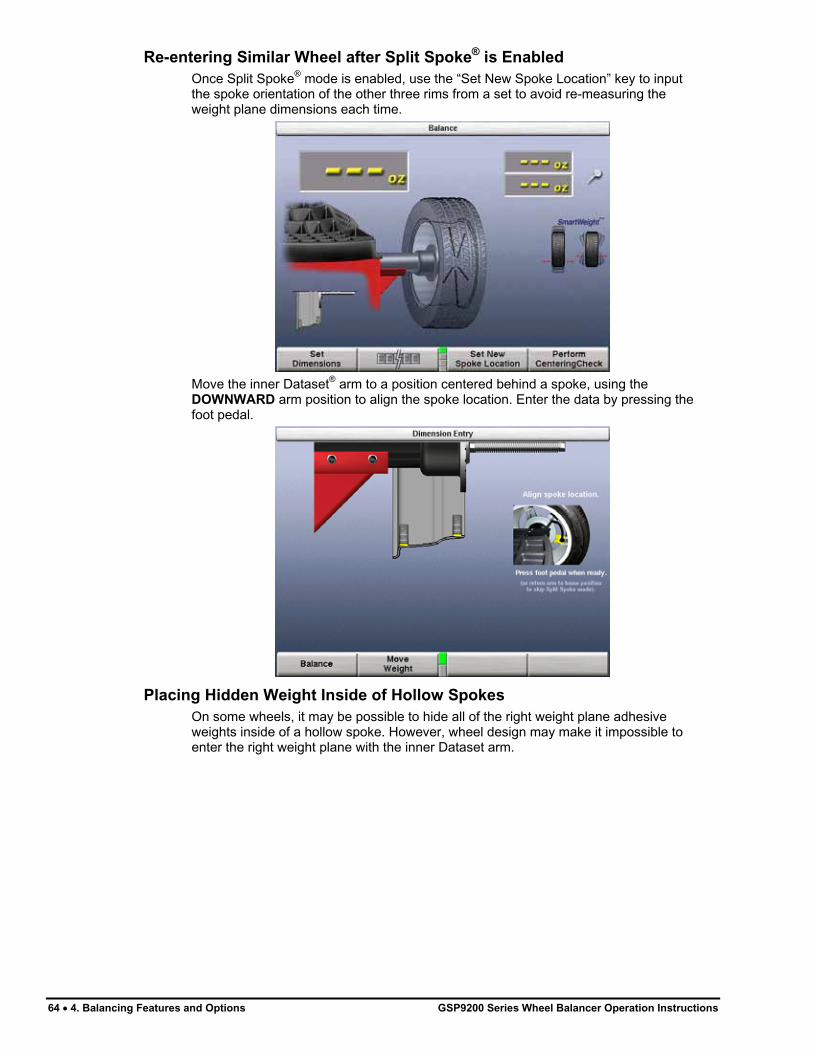
Re-entering Similar Wheel after Split Spoke® is Enabled
Once Split Spoke® mode is enabled, use the “Set New Spoke Location” key to input the spoke orientation of the other three rims from a set to avoid re-measuring the weight plane dimensions each time.
Move the inner Dataset® arm to a position centered behind a spoke, using the DOWNWARD arm position to align the spoke location. Enter the data by pressing the foot pedal.
Placing Hidden Weight Inside of Hollow Spokes
On some wheels, it may be possible to hide all of the right weight plane adhesive weights inside of a hollow spoke. However, wheel design may make it impossible to enter the right weight plane with the inner Dataset arm.
64 � 4. Balancing Features and Options GSP9200 Series Wheel Balancer Operation Instructions

The following example is in the mixed weight mode. Move the inner Dataset® arm to left plane position. Enter the data by pressing the foot pedal.
Measure the distance from the left weight plane to the desired right weight plane, using a tape measure. This distance must be in millimeters (convert inches to millimeters by multiplying by 25.4). Measure the weight plane diameter manually, using caliper or tape measure.
NOTE: This may need to be done before the wheel is mounted on the GSP9200.
Add the measurement from the left weight plane to the desired right weight plane to the distance to the inner rim lip and enter this new dimension manually.
Enter the weight plane distance (mm) and diameter (in) manually.
Close safety hood.
Press the green “START” button if “Hood Autostart” is disabled.
After wheel comes to a complete stop, raise safety hood.
GSP9200 Series Wheel Balancer Operation Instructions 4. Balancing Features and Options � 65

Place left plane weight (if in DYNAMIC mode) per the balance procedure being performed. Refer to “Balancing Procedures,” page 25.
Press the green “START” button with the safety hood in the RAISED position and the GSP9200 will servo to the location for the right adhesive weight plane (dynamic) or the static adhesive weight plane (static), aligned with the first spoke.
With the servo enabled, attach the adhesive weight behind the first spoke using the weight amount shown on the LCD.
Press the green “START” button with the safety hood in the RAISED position and the GSP9200 will servo to the location for the second spoke.
Attach the appropriate weight as displayed on the console.
All weight plane displays should show “OK,” after checkspin.
SPLIT SPOKE® balancing procedure is complete.
4.12 RimScan™ Wheel Profile Scanner
RimScan™ wheel profile scanner analyzes and reproduces a cut-away view of the rim profile. This is highly advantageous for difficult applications and for accurately placing each individual wheel weight. RimScan combined with SmartWeight® makes single corrective weight placement simpler and more frequent, further reducing or eliminating the static residual.
RimScan is available only if SmartWeight® is enabled. RimScan is designed for adhesive weights or mixed weight balancing methods.
Setting Dimensions with RimScan
Select “Balance” from the main screen and install the wheel on the spindle.
66 � 4. Balancing Features and Options GSP9200 Series Wheel Balancer Operation Instructions

NOTE: For mixed weights, first move the inner Dataset® arm in the UPWARD position to the clip-on weight location and tap foot pedal to measure the distance and diameter dimensions prior to performing RimScan.
To initiate RimScan, pull the inner Dataset® arm away from the weight tray and turn to the down position.
The rim profile can be scanned starting with the rim lip, or from the inside of the wheel. Place the dataset arm against the rim at the desired location, depress and hold the foot pedal. The RimScan screen will automatically appear.
GSP9200 Series Wheel Balancer Operation Instructions 4. Balancing Features and Options � 67

As shown below, draw the dataset arm across the rim to produce an on-screen, live progress of the wheel representation. While it is not necessary to “draw” slowly with the dataset arm, it will produce a more accurate representation of the rim profile especially with rims having multiple steps or taper.
When the scan is complete, release the foot pedal and a rim illustration will appear with weight planes automatically placed at correct positions for tapers or steps.
RimScan is compete. Select “Balance to continue to the balance screen. After a scan is performed the profile will appear on the balance screen.
68 � 4. Balancing Features and Options GSP9200 Series Wheel Balancer Operation Instructions

The user has the ability to change corrective weight location(s). Select “Move Weight” and change weight position with the Control knob. Push the control knob to switch between left and right weight planes.
Select “Find Best Location” to let the balancer decide what is the optimum corrective weight location. If by chance the user-selected weight positions are unacceptable, “Find Best Location” will return the weights to the optimum positions.
Real-Time Predictions with RimScan and SmartWeight®
Once dimensions are measured, the balance screen will display the corrective weight required and the SmartWeight® static and couple forces, along with the RimScan display identifying the weight location. If a single corrective weight is required RimScan and SmartWeight® work together to further reduce the amount of weight used.
GSP9200 Series Wheel Balancer Operation Instructions 4. Balancing Features and Options � 69

Select “Set Dimensions” to illustrate RimScan profile. If the weight location cannot be achieved or is undesirable, turn the control knob to change the weight position. As the position changes, the SmartWeight® force graphs will display a prediction of the force results corresponding to the weight.
4.13 BDC Laser Adhesive Weight Locator
Servo-Activated Laser automatically locates BDC to aid in fast adhesive weight positioning.
The BDC laser locator automatically displays a vivid line at bottom dead center after a wheel has been spun. The laser turns off when the wheel is spun again.
CAUTION: Use of controls or adjustments or performance of procedures other than those specified herein may result in hazardous radiation exposure.
This Laser Product is designated as Class 1M during all procedures of operation.
Never look directly into the laser. Doing so may cause serious injury.
Operation accessible radiation fields:
Wavelength 635-660nm Laser Power for Classification <390uW via 7mm aperture Beam Diameter <5mm at aperture Divergence <1.5mrad x <2rad Transverse Beam Mode TEM00
70 � 4. Balancing Features and Options GSP9200 Series Wheel Balancer Operation Instructions

4.14 Optional HammerHead™
TDC Laser Adhesive Weight Locator
The balancer will find the TDC for the left or right weight plane if “Servo-Stop” is enabled. “Servo-Stop” will hold the wheel in the TDC position while the servo-activated laser automatically locates TDC to aid in fast clip-on weight positioning.
The HammerHead™ TDC Laser System automatically displays a vivid line at top dead center after a wheel has been spun. The laser turns “off” when the wheel is spun again.
CAUTION: Use of controls or adjustments or performance of procedures other than those specified herein may result in hazardous radiation exposure. This Laser Product is designated as Class 1M during all procedures of operation. Never look directly into the laser. Doing so may cause serious injury.
Operation accessible radiation fields: Wavelength 635-660nm Laser Power for Classification <1mW via 7mm aperture Beam Diameter <5mm at aperture Divergence <1.5mrad x <2rad Transverse Beam Mode TEM00
GSP9200 Series Wheel Balancer Operation Instructions 4. Balancing Features and Options � 71

Specific Precautions / HammerHead™ TDC Laser System
The TDC (Top Dead Center) Laser Indicator is a class 2M laser designed to aid in applying clip-on weights. The laser is not a field serviceable or adjustable part.
Use caution in regard to reflective materials around the laser and never look into the laser beam.
72 � 4. Balancing Features and Options GSP9200 Series Wheel Balancer Operation Instructions
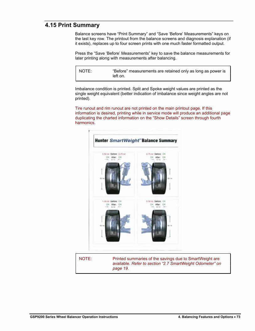
GSP9200 Series Wheel Balancer Operation Instructions 4. Balancing Features and Options � 73
4.15 Print Summary
Balance screens have “Print Summary” and “Save ‘Before’ Measurements” keys on the last key row. The printout from the balance screens and diagnosis explanation (if it exists), replaces up to four screen prints with one much faster formatted output.
Press the “Save ‘Before’ Measurements” key to save the balance measurements for later printing along with measurements after balancing.
NOTE: “Before” measurements are retained only as long as power is left on.
Imbalance condition is printed. Split and Spoke weight values are printed as the single weight equivalent (better indication of imbalance since weight angles are not printed).
Tire runout and rim runout are not printed on the main printout page. If this information is desired, printing while in service mode will produce an additional page duplicating the charted information on the “Show Details” screen through fourth harmonics.
NOTE: Printed summaries of the savings due to SmartWeight are available. Refer to section “2.7 SmartWeight Odometer” on page 19.


5. Equipment Information
5.1 Software Identification
Selecting “Identify Software” from the logo screen will display the software version. Trademarks may also be viewed from this screen.
5.2 Program Cartridge Removal and Installation
Remove the rear cover from the support assembly for the LCD display by removing the six #8 screws. Set the rear cover and attaching hardware aside.
Insert to program cartridge into the cartridge jack located on the side of the board within the support assembly. Verify that program cartridge is fully seated.
PROGRAM
CARTRIDGE
INSTALLED
SECURITY KEY
INSTALLED
Install the supplied electronic security key in the button socket on the board within the support assembly.
Taking care not to pinch any cables, re-install the rear cover to the support assembly with the previously removed six #8 screws.
AFTER INSTALLING PROGRAM CARTRIDGE:
View setup options by selecting “Setup” from the “logo” screen. Change setup options to the desired settings. Press “Store Setup” to complete “Setup” procedures.
NOTE: If indicated after installation, the GSP9200 must be
completely re-calibrated after program cartridge
installation. Refer to “Calibration Procedures,” page 87.Calibration tool, 221-672-1, is required.
GSP9200 Series Wheel Balancer Operation Instructions 5. Equipment Information � 75

5.3 Balancer Set Up
The “Set Up” primary screen contains a list box of set up items and may be selected from the second row of softkeys on the “Logo” primary screen. As the set up features are individually highlighted by selecting “�” or “�”, the equipment components for each set up procedure are shown in yellow on the illustrated GSP9200.
Change set up features by selecting “Set Up Selected Item.” The gray box at the top of the item set up menu displays the current setting for each feature. The blue box in the middle of the set up screen describes the highlighted choice from the list box below. Use the soft keys to select the desired setting for each feature. Select “OK” when the desired choice is highlighted. To exit set up procedures and save changes that were made, select “Store Set Up” from the menu. The screen will automatically return to the “Logo” screen.
NOTE: The set up information is not stored until “Store Set Up” is pressed on the wheel balancer “Set Up” screen.
To abandon the set up procedures without saving changes, select the “Cancel” key or simply reset the system.
Display Language
Selects the language for display.
Printer
Select the type of printer connected to the system.
Printout Language
Selects the language for printouts.
Printout Paper Size Selection
Selects the correct size paper for printouts.
Hood Autostart Feature
Enables or disables automatically starting the spin upon closing the hood.
Servo-Stop
Enables or disables the intelligent DC motor drive to automatically rotate the wheel to the weight or ForceMatch Mark positions. Servo-Push may also be enabled, which allows pushing the wheel (approximately 1/8 of a revolution) to cause the intelligent DC motor drive to automatically rotate the wheel to the next weight positions. Pressing the “START” key may still be used for this function.
Weight Units
Selects English or Metric units for displaying wheel weights.
5.4 Service Mode Setup and Features
NOTE: Service Mode should only be used by authorized users or Hunter Engineering Company authorized service personnel. Some options in Service Mode may not be available. Options in Service Mode are dependent on the specific authorization key installed.
Enter “Service Mode” by pressing and holding K2 and K3 and pressing the Reset softkey twice quickly from any screen. This will immediately return the user to the main screen and “Service Mode” will then be displayed at the top of the screen.
“Service Mode” enables the selection of advanced customized settings and hardware specific setup.
76 � 5. Equipment Information GSP9200 Series Wheel Balancer Operation Instructions

Set Date and Time
Selects the correct date and time for both display and printouts.
Setting Up the Balance Limits
Enables and sets limits for both standard wheel balancing and SmartWeight® balancing.
OUNCE/GRAM
STATIC BLIND
AMOUNT
SHOW
OUNCES/GRAMS
NON-SMARTWEIGHT
BALANCING
ENABLE/DISABLE
SWITCH
OUNCE/GRAM
DYNAMIC
BLIND
AMOUNT
ROUND AMOUNT
SELECTION
NORMAL/LARGE
ASSEMBLIES SWITCH
ENABLE/DISABLE
SMARTWEIGHT
SWITCH
STATIC FORCE
LIMITS
COUPLE FORCE
LIMITS
WEIGHTSAVER
RESIDUAL GOAL
SHOW PER-SPIN
SAVINGS
SHOW
ACCUMULATED
SAVINGS
Click on the control knob to change the fields. The current selected field will be highlighted with a description at the bottom of the screen.
When “Large Assemblies” has been selected the Static and Couple force limits will change to reflect those values.
Main Selections
Setting Up the Weight Units
Selects the corrective weight units as ounces or grams.
Setting Up the Ounce Round Amount
Selects the amount to which ounce weights are rounded. Ounce Round Amount options include 0.05 ounces, and 0.25 ounces.
Setting Up the Gram Round Amount
Selects the amount to which gram weights are rounded. Gram Round Amount options include 1 gram, and 5 grams.
Setting the Limits Displayed
Limits Displayed switches the SmartWeight® settings between Normal Assemblies and Large Assemblies.
GSP9200 Series Wheel Balancer Operation Instructions 5. Equipment Information � 77

Non-SmartWeight Options
Setting Up the Ounce Blind Amount
Selects the amount below which ounce weights show as zero. Ounce Blind Amount options include 0.20 ounces, 0.30 ounces, and 0.58 ounces.
Setting Up the Gram Blind Amount
Selects the amount below which gram weights show as zero. Gram Blind Amount options include 4 grams, 8 grams, and 16 grams.
SmartWeight® Options - Setting Up the Force Limits
NOTE: The force limits values are set to exact default measurements and should not be changed except by qualified personnel for very specific reasons.
Force Limits can be adjusted for the up and down static force and the side-to-side couple force.
Any changes to the limits can be reset by selecting the “Set Factory Defaults” softkey.
WeightSaver® Residual Goal
WeightSaver® residual goal is the percent of the shimmy force limit intentionally left in the assembly to save weight. A lower value favors lower residual shimmy and a higher value favors weight savings.
The Residual Goal has a default of 75% of the maximum allowed shimmy force to maximize weight savings.
WEIGHTSAVER
RESIDUAL GOAL
PERCENTAGE
Prompt for Wheel Assembly ID
Enables or disables prompting of the user to enter the current assembly before saving.
78 � 5. Equipment Information GSP9200 Series Wheel Balancer Operation Instructions

Spindle Type
Sets the spindle to the correctly installed spindle type. Select either the standard threaded spindle or the optional Auto-Clamp pneumatic spindle.
HammerHead™
Setup options for the HammerHead option.
5.5 Updating TPMS Specifications and Hunter Help Files
NOTE: The following instructions pertain to the updating TPMS specifications and Hunter Help Files for the first time. Additional yearly updates are performed in a similar manner, using an update code. Additional instructions will be supplied at that time.
TPMS specifications and Hunter Help Files may be updated by downloading a new file from the Web to the TPMS USB flash drive supplied with the balancer.
To download TPMS specifications and Hunter Help Files, the following items are required:
A Hunter Balancer (version 3.0 software or higher required for TPMS specifications) (version 3.1 software or higher required for Hunter Help Files) A PC with an internet connection User Name and Password TPMS USB flash drive
If Software Version is Less than 3.0 - Locate Balancer Serial Number
From the logo screen, select “Identify Software” ( ). The Identify Software screen will be displayed.
Locate the System ID section. Write down the first number that is shown. This is the password needed to retrieve updates.
GSP9200 Series Wheel Balancer Operation Instructions 5. Equipment Information � 79
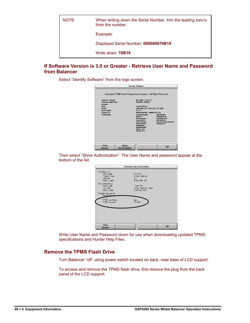
NOTE: When writing down the Serial Number, trim the leading zero’s from the number.
Example:
Displayed Serial Number: 000000070B19
Write down: 70B19
If Software Version is 3.0 or Greater - Retrieve User Name and Password
from Balancer
Select “Identify Software” from the logo screen.
Then select “Show Authorization”. The User Name and password appear at the bottom of the list.
Write User Name and Password down for use when downloading updated TPMS specifications and Hunter Help Files.
Remove the TPMS Flash Drive
Turn Balancer “off” using power switch located on back, near base of LCD support.
To access and remove the TPMS flash drive, first remove the plug from the back panel of the LCD support.
80 � 5. Equipment Information GSP9200 Series Wheel Balancer Operation Instructions

NOTE: If the balancer is not equipped with a plug, then the entire back panel should be removed to access the drive.
Pull the TPMS flash drive from the USB port within the LCD support.
Download Specifications
Using a PC connected to the internet, insert the TPMS flash drive into one of the USB ports.
Log on to http://www.webspecs.net/.
Enter tpms as the User Name. Enter the password for the balancer and click “Logon”.
NOTE: User Name and password are case sensitive.
click
tpms
GSP9200 Series Wheel Balancer Operation Instructions 5. Equipment Information � 81

Enter your customer information. Make sure your email address is correct. Click on “Submit”.
Enter your information ALL FIELDS
ARE REQUIRED
click
Click the “Download TPMS and Hunter Help Files” link.
click
Select the file(s) you wish to download.
NOTE: Both the TPMS Data (version 3.0 software or higher required for TPMS specifications) and Hunter Help Files (version 3.1 software or higher required for Hunter Help Files) should be downloaded for initial setup.
click click
82 � 5. Equipment Information GSP9200 Series Wheel Balancer Operation Instructions

Choose "Save" or "Save to Disk", depending on the web browser being used. Browse to the location of your storage device (TPMS thumb drive). Click "Save." The files should be saved to the root level of the thumb drive.
When the file(s) has been successfully saved to your TPMS flash drive, you may log out and proceed to upload the TPMS specifications and Hunter Help Files to the balancer.
Upload TPMS Specifications and Hunter Help Files to the Balancer
Insert the TPMS flash drive into the balancer’s USB port located in LCD support.
Re-install the plug over the access hole in the back panel of the LCD support.
Turn Balancer “on” using power switch located on back.
Beginning at the Logo Screen, press either “Update TPMS” (version 3.0 software or higher required for TPMS specifications) or “Update Help Files” (version 3.1 software or higher required for Hunter Help Files) on the bottom row of the softkeys.
NOTE: The “Update TPMS” and “Update Help Files” softkeys will only be available if a valid TPMS file or valid Hunter Help File exists at the root level of the USB drive. Only files that have been downloaded using this balancer’s user name and password will enable the update procedure.
GSP9200 Series Wheel Balancer Operation Instructions 5. Equipment Information � 83
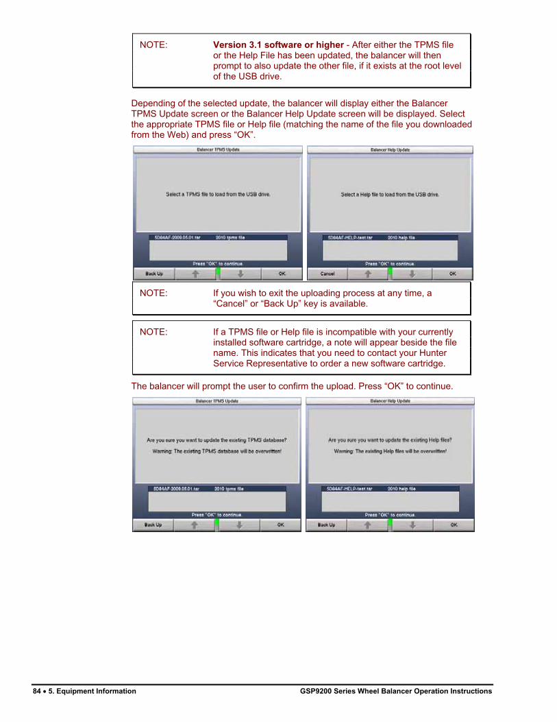
NOTE: Version 3.1 software or higher - After either the TPMS file or the Help File has been updated, the balancer will then prompt to also update the other file, if it exists at the root level of the USB drive.
Depending of the selected update, the balancer will display either the Balancer TPMS Update screen or the Balancer Help Update screen will be displayed. Select the appropriate TPMS file or Help file (matching the name of the file you downloaded from the Web) and press “OK”.
NOTE: If you wish to exit the uploading process at any time, a “Cancel” or “Back Up” key is available.
NOTE: If a TPMS file or Help file is incompatible with your currently installed software cartridge, a note will appear beside the file name. This indicates that you need to contact your Hunter Service Representative to order a new software cartridge.
The balancer will prompt the user to confirm the upload. Press “OK” to continue.
84 � 5. Equipment Information GSP9200 Series Wheel Balancer Operation Instructions

GSP9200 Series Wheel Balancer Operation Instructions 5. Equipment Information � 85
The balancer may take a few minutes to complete the uploading process.
After either the TPMS file or the Help File has been updated, the balancer will then prompt to also update the other file, if it exists at the root level of the USB drive.
Once the upload is complete, restart the balancer turning it “off” and then back “on” using power switch.
The updated TPMS specifications and Help files are now ready for use.


6. Calibration and Maintenance
6.1 Calibration Procedures
The “Calibration” primary screen can be selected by pressing “Calibrate” from the “Logo” screen. The “Calibration Procedures” primary screen contains a list box of calibration procedures. As the procedures are individually highlighted by selecting “�” or “�”, the equipment components to be calibrated for each procedure are shown in yellow on the illustrated GSP9200.
Calibration can be performed on the Balancer, the Inner Dataset Arm, and the Outer Dataset Arm.
Begin calibration procedures by selecting “Begin Procedure.” When finished calibrating, select “Exit.”
Throughout the calibration procedures, “Back Up” can be selected to return to the previous step.
The calibration weight used for calibrating the balancer and the inner dataset arm is stored in one of the weld nuts located on the back of the base assembly or in the weight tray.
Dataset® arm require the optional calibration tool, 221-672-1.
GSP9200 Series Wheel Balancer Operation Instructions 6. Calibration and Maintenance � 87

Balancer (3 Spin Procedure)
CAUTION: Remove all cones from shaft prior to beginning calibration procedures.
Select “Calibrate” from the “Logo” screen.
Select “Balancer” from the “Calibration Procedures” primary screen.
Select “Begin Procedure.”
Spin 1:
Lower hood and press the green “START” button.
Spin 2:
Lift hood and install calibration weight on the left side of the faceplate in either hole by threading the calibration weight clockwise into the hole.
Rotate calibration weight to the 12:00 position.
Select “Enter 12:00 Position.”
Lower hood and press the green “START” button.
Spin 3:
Lift hood, remove calibration weight, and install calibration weight in the same hole on the opposite side of the faceplate by threading calibration weight clockwise into the hole.
Lower hood and press the green “START” button.
If calibration succeeds, the LCD will display a “Calibration Complete” message.
If calibration fails, such as if the weight was placed incorrectly during the procedure, the GSP9200 will keep previous balancer calibration data.
88 � 6. Calibration and Maintenance GSP9200 Series Wheel Balancer Operation Instructions

Inner Dataset® Arm (Calibration Tool, 221-672-1, Required)
Select “Calibrate” from the “Logo” screen.
Select “Inner Dataset” from the “Calibration Procedures” primary screen.
Select “Begin Procedure.”
Verify that the inner arm is in the “home” position at the top of the weight tray and is not moving. Tap the foot pedal once or press “Enter Cal Step.”
Place the calibration tool on the shaft using the middle spindle shaft slot. Align the center hole of the calibration tool with a calibration weight thread hole, and tighten the calibration weight securing the calibration tool to the hub face as shown below.
CAUTION: Do NOT operate balancer with calibration tool attached. Remove calibration tool immediately after performing this procedure.
Press “OK” when calibration tool is installed.
Rotate the calibration tool slowly by hand, clockwise until the GSP9200 beeps.
NOTE: You may have to rotate the tool up to 1 1/2 turns.
GSP9200 Series Wheel Balancer Operation Instructions 6. Calibration and Maintenance � 89

Position the calibration tool parallel to the floor. Tap the foot pedal once or press “OK.”
NOTE: To verify that the tool is parallel to the floor, measure from both ends of the calibration tool to the floor. The measurement will be the same at both ends when the tool is parallel to the floor.
Place the inner Dataset® arm at upward position “1.” Tap the foot pedal once or press “Enter Cal Step.”
NOTE: If the inner Dataset® arm is unstable while entering any step, a long, high-pitched tone will sound to advise that the step has NOT been entered. Stabilize the arm and re-enter the step.
Place the inner Dataset® arm at upward position “2.” Tap the foot pedal once or press “Enter Cal Step.”
Place the inner Dataset® arm at upward position “3.” Tap the foot pedal once or press “Enter Cal Step.”
Place the inner Dataset® arm at downward position “4.” Tap the foot pedal once or press “Enter Cal Step.”
Place the inner Dataset® arm at downward position “5.” Tap the foot pedal once or press “Enter Cal Step.”
90 � 6. Calibration and Maintenance GSP9200 Series Wheel Balancer Operation Instructions

Place the inner Dataset® arm at downward position “6.” Tap the foot pedal once or press “Enter Cal Step.”
Remove the calibration weight from the calibration tool and return it to its storage position.
Position the calibration tool parallel to the spindle shaft on the hub using the hub mounting slot as shown.
Place the inner Dataset® arm at the position “7.” Tap the foot pedal once or press “Enter Cal Step.”
Place the inner Dataset® arm at the position “8.” Tap the foot pedal once or press “Enter Cal Step.”
Place the inner Dataset® arm at the position “9.” Tap the foot pedal once or press “Enter Cal Step.”
Inner Dataset® arm calibration is complete.
Outer Dataset® Arm (Calibration Tool, 221-672-1, Required)
Select “Calibrate” from the “Logo” screen.
Select “Outer Dataset” from the “Calibration Procedures” primary screen.
Select “Begin Procedure.”
With the hood in the raised position, verify that the outer arm is in the “home” position and that the arm and hood are not moving. Tap the foot pedal once or press “Enter Cal Step.”
GSP9200 Series Wheel Balancer Operation Instructions 6. Calibration and Maintenance � 91

Place the calibration tool on the spindle shaft using the spindle shaft slot closest to the end of the calibration tool and hold in an upright position, flat against the hub.
NOTE: The calibration tool should be in full contact with the hub face, but will allow a gap to exist between the tool and the hub face.
GAP HERE IS
NORMAL
HOLD FIRMLY
Place the outer Dataset® arm at position “1.” Tap the foot pedal once or press “Enter Cal Step.”
NOTE: If the outer Dataset® arm is unstable while entering any step, a long, high-pitched tone will sound to advise that the step has NOT been entered. Stabilize the arm and re-enter the step.
Place the outer Dataset® arm at position “2.” Tap the foot pedal once or press “Enter Cal Step.”
Place the outer Dataset® arm at position “3.” Tap the foot pedal once or press “Enter Cal Step.”
Place the calibration tool on the hub using the hub mounting slot as shown.
Place the outer Dataset® arm ball in the hole for position “4.” Tap the foot pedal once or press “Enter Cal Step.”
Place the outer Dataset® arm at position “5.” Tap the foot pedal once or press “Enter Cal Step.”
Place the outer Dataset® arm at position “6.” Tap the foot pedal once or press “Enter Cal Step.”
Outer Dataset® arm calibration is complete.
92 � 6. Calibration and Maintenance GSP9200 Series Wheel Balancer Operation Instructions
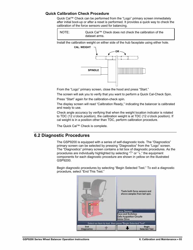
Quick Calibration Check Procedure
Quick Cal™ Check can be performed from the “Logo” primary screen immediately after initial boot-up or after a reset is performed. It provides a quick way to check the calibration of the force sensors used for balancing.
NOTE: Quick Cal™ Check does not check the calibration of the dataset arms.
Install the calibration weight on either side of the hub faceplate using either hole.
OR
SPINDLE
CAL. WEIGHT
From the “Logo” primary screen, close the hood and press “Start.”
The screen will ask you to verify that you want to perform a Quick Cal-Check Spin.
Press “Start” again for the calibration-check spin.
The display screen will read “Calibration Ready,” indicating the balancer is calibrated and ready to use.
Check angle accuracy by verifying that when the weight location indicator is rotated to TDC (12 o’clock position), the calibration weight is at TDC (12 o’clock position). If cal weight is in a position other than TDC, perform calibration procedure.
The Quick Cal™ Check is complete.
6.2 Diagnostic Procedures
The GSP9200 is equipped with a series of self-diagnostic tools. The “Diagnostics” primary screen can be selected by pressing “Diagnostics” from the “Logo” screen. The “Diagnostics” primary screen contains a list box of diagnostic procedures. As the procedures are individually highlighted by selecting “�” or “�,” the equipment components for each diagnostic procedure are shown in yellow on the illustrated GSP9200.
Begin diagnostic procedures by selecting “Begin Selected Test.” To exit a diagnostic procedure, select “End This Test.”
GSP9200 Series Wheel Balancer Operation Instructions 6. Calibration and Maintenance � 93

Most of the diagnostic data is available for the sole purpose of conveying information to your Hunter Service Representative. Your service representative may request information from these screens to diagnose service concerns. The ability to convey diagnostic data to the representative prior to servicing the GSP9200 will expedite service to your equipment.
You may also perform diagnostic tests to diagnose concerns yourself. For example, “Keys and Switches” can be tested to verify the proper operation of each key and switch.
Force Sensors
Tests both force sensors and displays samples from the last spin.
Keys and Switches
Tests keypad and switches. Each working keypad and switch will beep upon closure to verify that it is in working order.
Data Acquisition Circuits
Tests Data Acquisition Circuits (displays real-time samples as acquired by main board electronics).
Motor Drive
Tests the motor drive using manual control.
6.3 Printing
A “Print” softkey is offered on some screens. Pressing the “Print” key will activate the printer and print the information shown on the current screen.
6.4 Cleaning the Console
When cleaning the console, use window cleaning solution to wipe off the display console and cabinet. Do not spray window cleaning solution directly onto control panel or LCD. Power should be “OFF” prior to cleaning the LCD.
WARNING: Exposing the balancer to water either by hose, bucket,
or weather may cause risk of electrical shock to
operator or bystanders and will damage the electrical
system. Place, store, and operate the balancer only in a
dry, sheltered location.
94 � 6. Calibration and Maintenance GSP9200 Series Wheel Balancer Operation Instructions

6.5 Maintenance
Spindle Hub Face and Shaft
Keep the shaft and wing nut threads clean and lubricated. Lubricate the shaft without contaminating the hub face. Select “Clean Spindle Threads” from the “Balance” primary screen. Run the edge of a rag between the threads while the spindle is slowly turned by the motor drive. If any signs of dirt or debris appear on the spindle threads, the spindle should be cleaned immediately prior to mounting a wheel.
CAUTION: Failure to clean spindle properly will result in a loss of clamping force. Due to the force applied to the wheel by the load roller, it is critical to maintain optimum clamping force.
Lubricate the shaft with a coating of light lubricant with Teflon® such as Super Lube®
by Loctite after cleaning. Do not lubricate the spindle hub face mounting surface. This could cause slipping between the wheel and the hub face. Keep the hub face mounting surface clean and dry.
BDC Laser Adhesive Weight Locator Maintenance or Service
CAUTION: Use of controls, adjustments, or performance of procedures other than those specified herein may result in hazardous radiation exposure.
This Laser Product is designated as Class 1M during all procedures of operation.
Never look directly into the laser. Doing so may cause serious injury.
Do not intentional use a reflective device to enhance or re-direct the laser.
Do not operate the laser if the cover or seal is damaged.
There is no required maintenance or service to keep the BDC Laser in compliance.
Any necessary repair or maintenance should be done by the factory only. The BDC Laser Locator has no field serviceable parts.
The unit should never be opened or modified.
The unit should never be opened or modified.
Optional HammerHead™ TDC Laser Clip-On Weight Locator
Maintenance or Service
CAUTION: Use of controls, adjustments, or performance of
procedures other than those specified herein may result
in hazardous radiation exposure.
This Laser Product is designated as Class 2M during all
procedures of operation.
Do not stare into the beam or view directly with optical
instruments. Doing so may cause serious injury.
Do not intentionally use a reflective device to enhance
or re-direct the laser.
Do not operate the laser if the cover or seal is damaged.
There is no required maintenance or service to keep the HammerHead™ TDC Laser System in compliance.
The laser is not a field serviceable or an adjustable part.
GSP9200 Series Wheel Balancer Operation Instructions 6. Calibration and Maintenance � 95

96 � 6. Calibration and Maintenance GSP9200 Series Wheel Balancer Operation Instructions
Any necessary repair or maintenance should be done by the factory only. The HammerHead™ TDC Laser System has no field serviceable parts.
The unit should never be opened or modified.
6.6 Mounting Cone Maintenance
Keep the mounting cones clean and lubricated. Lubricate with a coating of light lubricant with Teflon® such as Super Lube® by Loctite.
Do not use cones in any way that is not described in this operation manual. This could cause damage to the mounting cone and not allow for proper mounting of the wheel.

7. Glossary
Amplitude (Magnitude)
The amount of force or the intensity of the vibration.
Back Coning
When the wheel requires the cone to center the wheel on the balancer’s shaft from the backside, primarily due to the chamfer of the wheel. Also referred to as Back-Cone Mounting.
Backspacing
The distance measured from the mounting face to the back edge of the wheel.
BDC
The abbreviation for bottom dead center also referred to as 6 o’clock.
Bead seating
The process of seating the tire to the rim bead seats. Bead seating preferably occurs just after the tire and rim have been assembled, but may gradually change and optimize over a longer period. If loaded with the GSP9200 load roller or driven, the position of the bead may optimize or always remain seated improperly, unless the tire is demounted, lubricated, and remounted. However, the load force and its’ relatively short duration will not necessarily solve defective mounting of the tire bead seat to the rim seat.
Bolt Pattern Circle
The diameter of an imaginary circle drawn through the center of each lughole, and virtually always on the same centerline as the hub bore of the wheel.
Computerized Vibration Analyzer
A device used to determine the frequency of the vibration by isolating the vibrations with the greatest magnitude.
Cycle
One complete disturbance.
Dampen
To decrease the magnitude of a vibration or sound.
Dampers
Used to reduce the magnitude of a given vibration. Rubber is commonly used to isolate and dampen vibrations.
Dataset®
The inner and outer electronic arms on the GSP9200. By positioning the Dataset arms and entering data using the foot pedal, rim dimensions can be recorded for balancing.
Dynamic Balance
A procedure that balances the wheel assembly by applying correction weights in two planes so that up and down imbalance and side to side imbalance are eliminated.
GSP9200 Series Wheel Balancer Operation Instructions 7. Glossary � 97

Force Matching™
A method of aligning the high spot of the tire’s radial force variation with the low spot of rim runout to decrease rolling vibration in the wheel assembly.
Forced Vibration
Vibrates when energy is applied.
Free Vibration
Continues to vibrate after the outside energy stops.
Frequency
The number of disturbances that occur per unit of time.
Front Coning
When the wheel requires the cone to center the wheel on the balancer’s shaft from the front. Also referred to as Front-Cone Mounting.
Harmonic
A vibration that is identified by the number of occurrences per revolution. For example, a 1st harmonic vibration has a once per revolution vibration component.
Hertz
A unit of frequency: one disturbance per second.
Hub Centric
The wheel is centered using the center hole of the wheel.
Inflation Station
A feature on newer models of the GSP9200 that automatically inflates or deflates tires to a predetermined air pressure.
Lateral Runout
The amount of side-to-side movement as the tire/wheel assembly rotates.
Lug Centric
The wheel is centered using the lugholes rather than the wheel center hole.
Magnitude (Amplitude)
The amount of force or the intensity of the vibration.
MatchMaker™
Allows the operator to match up four identical tires on identical rims, to achieve the optimal combination of match mounting.
Natural Frequency
The point at which an object will vibrate the easiest.
Order
The number of disturbances per cycle (rotation). For example, a 1st order vibration occurs once per cycle, and a 2nd order vibration occurs twice per cycle.
P, P/SUV, LT
98 � 7. Glossary GSP9200 Series Wheel Balancer Operation Instructions

“P Tires” refers to passenger tires, “LT Tires” refers to light truck tires, and “P/SUV Tires” refers to P-Rated sport utility vehicle tires.
Phase
The position of a vibration cycle relative to another vibration cycle in the same time reference.
Phasing
The cycle pattern of two or more vibrations that overlap and combine to increase the overall magnitude.
Pressure Ring
The accessory used to prevent the wing nut from contacting the wheel when on the balancer shaft.
Quick-Thread®
Motor assisted threading of the wing nut for quick installation and removal.
Radial Force Variation (RFV)
A term describing a measurement of the tire uniformity, under load, measuring the variation of the load acting toward the tire center.
Radial Runout
A condition where the tire and wheel assembly is slightly out of round forcing the spindle to move up and down as the vehicle rolls along a smooth surface.
Reed Tachometer
A mechanical device that uses reeds to indicate the frequency and magnitude of the vibration.
Resonance
The point where a vibrating component’s frequency matches the natural frequency of another component.
Responding Component
The noticeable component that is vibrating.
Road Force�
A change in the force between the wheel and the axle while rotating under a load. Discrepancy in road force can cause a vibration although the tire and rim may be perfectly round and the tire is balanced.
Road Force� Measurement
A measurement of the wheel assembly as would be found from an actual road test of a vehicle. The GSP9200 is equipped with a load roller to take the Road Force�Measurement. The load roller places up to 1400 pounds of force on the spinning tire, and automatically measures the effects of loaded runout and tire stiffness to emulate tire/wheel assembly force variation.
Road Force� Variation
A change in force exerted on the axle by the tire/wheel assembly while rotating under load. Units of measurement are in pounds, Newton’s, etc.
Servo-Stop
GSP9200 Series Wheel Balancer Operation Instructions 7. Glossary � 99

100 � 7. Glossary GSP9200 Series Wheel Balancer Operation Instructions
The ability to locate varying positions of the tire/wheel assemblies and hold the position in place while correctional weights or OE-Matching marks are applied.
SmartWeight® Balancing Technology
SmartWeight® measures the forces placed on a wheel and balances in an effort to reduce those forces, thus saving weight, time, and money.
Source Component
A component causing another object to vibrate, such as a tire/wheel assembly.
Spindle-Lok®
A feature that locks the spindle in place by depressing the foot pedal.
Static Balance
A procedure that balances the wheel assembly using only a single weight plane.
TDC
An abbreviation for top dead center. Also referred to as 12 o’clock.
Torque Sensitive Vibration
The vibration occurs when accelerating, decelerating, or applying the throttle.
Total Indicated Reading (T.I.R.)
Data measurements taken by the load roller (measured in lbs. or kg) or Dataset® Arms (measured in inches or millimeters) representing the actual runout measured. The T.I.R. data represents the difference in value between the highest and lowest value measured.
Transference Path
The object(s) that transfer the frequency.
Vibration
A shaking or trembling, which may be heard or felt.
WeightSaver® Feature
WeightSaver® is the percentage of maximum shimmy allowed. The larger the percentage, the greater the weight savings.
Wheel Diameter
Dimension measured on the inside of the rim at the bead seats.
Wheel Offset
The measured distance between the mounting face of the wheel and the centerline of the rim.
Wheel Width
Dimension measured on the inside of the rim between the bead seats.


HUNTER RESEARCH AND TRAINING CENTER
HUNTER . . . dedicated to service excellence through professional training HUNTER TRAINING - Hunter operates the most advanced, up-to-date Training Center in the industry today.
The courses have been designed to meet the needs of new and experienced technicians who want to increase their mechanical and diagnostic capabilities. The low student-teacher ratio (average 7 to 1) and the emphasis on “hands-on” training (80% time in shop) create an excellent learning environment.
Highlights of the Hunter Training Center include: � An instruction staff with over 100 years of shop, field, and teaching
experience. � Fully-equipped service bays. � Classrooms equipped with modern teaching aids. � The most up-to-date wheel alignment, balancing service and brake
equipment on the market today.
Align 1 (Basic Alignment Theory and Practice) 3 day / 24 hrs Students will learn basic wheel alignment service through classroom and hands-on practice. Pre-alignment services, wheel alignment angle theory and wheel alignment equipment operation are the focus of this course. Basic wheel alignment adjustments will be demonstrated and students will practice on vehicles in a shop environment.
Align 2 (Advanced theory / Aftermarket Adjustment) 2-day / 16 hrs Modified vehicle wheel alignment is the focus of this course. Students learn how to use alignment angles to achieve vehicle handling performance in conjunction with ride height kits and modified tire/wheel packages. Aftermarket alignment adjustment kits are discussed and demonstrated.
Align 3 (Advanced Diagnostics and OE Procedures) 2-day / 16 hrs This class focuses on using advanced diagnostic angles and measurements to determine damaged suspension and steering components. Techniques used in finding damaged parts are reinforced with classroom scenarios and hands-on labs designed to both challenge and further embed these much needed skills.
Performance Tire (Basic and Advanced Tire Changing) 1-day 8 hrs Students will learn basic terminology and theory related to servicing tires and wheels. Students learn the proper techniques for changing tires on tulip clamp and table top tire changer designs. This course covers the proper tire changing techniques for low profile tires, run flat designs, and tire/wheel assemblies using TPMS.
GSP9700 Certification 2-days / 16 hrs This course combines the Rolling Smooth course with a certification program for Hunter Engineering’s GSP9700 Road Force Measurement system. Students use hands-on practice with the GSP9700 to gain a proficiency level acceptable to be deemed certified.
Rolling Smooth (Basic & Advanced vibration theory) 1-day / 8 hrs This course offers a study of vehicle vibration specific to wheel speed. The student will learn basic vibration terminology and vibration theory, Shop activities include the measurement of Road Force Variation, wheel runout and balance. Additional diagnostic tools are discussed.
HDT Alignment 1 (Fundamental Alignment) 3-day / 24 hrs Classroom and shop practice is used to teach the basic elements of Class 8 truck wheel alignment. Students will learn the proper method to measure and correct the required basic alignment angles using state of the art equipment. Trailer alignment is included.
HDT Alignment 2 (Advanced Alignment) 2-day / 16hrs The student will understand the cause and affect of basic alignment angles relative to ride quality, performance and tire life. Classroom and shop practice are used to learn the proper use of diagnostic alignment angles. Additional adjustment techniques and alignment system operation are explored in both the classroom and lab environment. Busses and RVs are discussed.
Hunter University’s eLearning courses are designed for all student levels and can be used as an integral supplement to instructor-led training courses. In-depth information, detailed graphics, video and modular segments assist the participant in expanding their knowledge base at a self-determined level. Go to www.hunter.com and click on TRAINING.
For further information about other classes offered or to schedule into a class, simply call the Hunter Research and Training Center at 1-800-448-6848.