GSM BTS312 Hardware Structure ISSUE4.0
23
1 Huawei Confidential. All Rights Reserved OME201101 GSM BTS312 Hardware Structure ISSUE 4.0 2 Internal Use Objectives Objectives Upon completion of this course, you will be able to: Know the functions and features of BTS Master the BTS hardware structure Master the signal processing of BTS
-
Upload
jorge-quispe-loa -
Category
Documents
-
view
250 -
download
5
Transcript of GSM BTS312 Hardware Structure ISSUE4.0

8/10/2019 GSM BTS312 Hardware Structure ISSUE4.0
http://slidepdf.com/reader/full/gsm-bts312-hardware-structure-issue40 1/23
1
Huawei Confidential. All Rights Reserved
OME201101 GSM BTS312
Hardware Structure
ISSUE 4.0
2 Internal Use
ObjectivesObjectives
Upon completion of this course, you will be
able to:
Know the functions and features of
BTS
Master the BTS hardware structure
Master the signal processing of BTS

8/10/2019 GSM BTS312 Hardware Structure ISSUE4.0
http://slidepdf.com/reader/full/gsm-bts312-hardware-structure-issue40 2/23
2
3 Internal Use
Chapter 1 Overview
Chapter 2 System Components
Chapter 3 Signal Processing
Chapter 4 Antenna and Feeder System
4 Internal Use
LocationLocation
MS: Mobile Station BTS: Base Transceiver Station
OMC: Operation and Maintenance Center
HLR: Home Location Register EIR: Equipment Identity Register
MSC: Mobile Switching Center VLR: Visitor Location Register SMC: Short Message Center
VM: Voice Mailbox
BSC: Base Station Controller
AUC: Authentication Center
PSTN
ISDN
PSPDN
Um Interface
BTS
BTS
BTS
BTS
OMC
HLR/AUC/EIR
BSC
MSC/VLR
SMC/VM
A Interface
MAPM A P
TUP,ISUPMS
MS
MS
8/10/2019 GSM BTS312 Hardware Structure ISSUE4.0
http://slidepdf.com/reader/full/gsm-bts312-hardware-structure-issue40 3/23
3
5 Internal Use
Features and FunctionsFeatures and Functions
High integration and low power consumption
15 radio carriers at the Abis sharing an E1 for transmission (15:1)
Support various transmission modes and complex topologies,
e.g. SDH, E1, microwave, satellite etc.
Support the configuration of up to S24/24/24 and facilitating
expansion
1-minute fast startup
6 Internal Use
Features and FunctionsFeatures and Functions
Support GSM900,DCS1800,EGSM and RGSM
Support GSM PHASE 1、PHASE 2 and PHASE 2+
Support GPRS and EDGE
Support baseband hopping and RF hopping Support FR, HR, EFR and AMR
Support A5/1 and A5/2 encryption/decryption

8/10/2019 GSM BTS312 Hardware Structure ISSUE4.0
http://slidepdf.com/reader/full/gsm-bts312-hardware-structure-issue40 4/23
4
7 Internal Use
Hardware StructureHardware Structure
DATA_BUS/CONTROL_BUS/TIMING_BUS
Externalcontrol
Externalalarm
E1TMU
Opt. fiber
xDSL TEU
PMUFH_BUS
CDU
PSU
TRX
TRX
TRX
Signal Processing UnitCommon Unit
CDU
CDU
antenna
antenna
antenna
Antenna Feeder Unit
TES
8 Internal Use
Boards in Cabinet:
CDU: Combiner & Divider Unit
TRX: Transceiver
PMU: Power Monitoring Unit
TMU: Timing/Transmission &
Management Unit
PSU: Power Supply Unit
TDU: Time Distribution Unit
TES: Transmission Extension
Power Supply Unit
TEU: Transmission Extension
Unit
Cabinet and BoardsCabinet and Boards
FAN BOX
SWITCH BOX
FAN BOX
AIR BOX
AIR BOX
P
S
U
P
S
U
P
S
U
P
S
U
P
S
U
P
S
U
P
M
U
T
M
U
T
E
S
T
E
U
T
M
U
T
E
U
T
R
X
T
R
X
T
R
X
T
R
X
C
D
U
C
D
U
T
R
X
T
R
X
T
R
X
T
R
X
C
D
U
C
D
U
T
R
X
T
R
X
T
R
X
T
R
X
C
D
U
C
D
U
TDU

8/10/2019 GSM BTS312 Hardware Structure ISSUE4.0
http://slidepdf.com/reader/full/gsm-bts312-hardware-structure-issue40 5/23
5
9 Internal Use
Chapter 1 Overview
Chapter 2 System Components
Chapter 3 Signal Processing
Chapter 4 Antenna and Feeder System
10 Internal Use
Chapter 2 System Componnents
Section 1 Common Unit
Section 2 Signal Processing Unit

8/10/2019 GSM BTS312 Hardware Structure ISSUE4.0
http://slidepdf.com/reader/full/gsm-bts312-hardware-structure-issue40 6/23
6
11 Internal Use
TMUTMU
Provide E1 connection interface
Provide channel multiplexing and flexible networking modes
Provide Man-machine interface (MMI) and operation &
maintenance link
Provide centralized BTS clock
Provide alarm signal input ports
Functions of TMUFunctions of TMU
12 Internal Use
Structure of TMUStructure of TMU
BSC
External synchronous clock
MMI (man-
machineInterface)
Environment
monitors
BIU
OMU
MCK Standby MCK
Extended BIUDBUS
CBUS
TDUTBUS
StandbyTMU
EAC

8/10/2019 GSM BTS312 Hardware Structure ISSUE4.0
http://slidepdf.com/reader/full/gsm-bts312-hardware-structure-issue40 7/23
7
13 Internal Use
Indictors on TMUIndictors on TMU
FlashFlash(0.5Hz): Normal
On or Off: AbnormalRunning StateGreenRUN
Slow flash
On: Free oscillation
Quick flash(4Hz):
Catching
Slow flash(1Hz): Locked
Off: Abnormal
Phase
identification
indicator
GreenPLL
Master Board: Slow
flash
Slave Board: Quick
flash
Slow flash(1HZ): Master
Quick flash(2Hz): Slave
Master/Slave
indicationGreenM/S
Off
On: Local Alarm
Flash: Remote Alarm
Off: Normal
E1
TransmissionGreenLI1,2,3,4
OnOn: Normal
Off: AbnormalPower GreenPWR
Normal StateExplanationMeaningColor Indicator
Name
T M U
M M I
T 1 3 M
F C K
T 2M
D B G
R S T
PW R
M /S
R U N
LI 1
LI 2
LI 3
LI 4
PL L
14 Internal Use
TDUTDU
Provide clock channels in one synchronous cell
Transfer E1 signals in the local cabinet
Provide alarming channels
Provide bus-control interfaces
Functions of TDUFunctions of TDU

8/10/2019 GSM BTS312 Hardware Structure ISSUE4.0
http://slidepdf.com/reader/full/gsm-bts312-hardware-structure-issue40 8/23
8
15 Internal Use
Position of TDUPosition of TDU
16 Internal Use
CabinetCabinet--top Connectorstop Connectors
(6) Clock interface (CKB1 and
CKB2)
(5) Storage battery
management
signal cable
interface (PWRC)
(4) Built-in optical
transmission E1 interface
(TRA1, TRA2, TRB1, and
TRB2)
(3) 120 E1 interface
(TME1)
(2) External alarm interface
(EAC1 and EAC2)
(1) Data bus
interface (DCF1)
(13) Cascading interface of CDU combined cabinet
(CDU)
(12) Feeder input interface
(ANT)
(11) External power
cable interface
(10) Grounding cable
interface for combined
cabinet (SHELLGND)
(9) External
synchronous
clock interface
(SYNC)
(8) 75 E1 interface (TX and
RX)
(7) Data bus interface
(DCF2)

8/10/2019 GSM BTS312 Hardware Structure ISSUE4.0
http://slidepdf.com/reader/full/gsm-bts312-hardware-structure-issue40 9/23
9
17 Internal Use
When the supply input is 220VAC,the AC/DC
module is used.
When the supply input is +24VDC,neither
DC/DC nor AC/DC module is used.
When the supply input is -48VDC,the DC/DC
module is used.
220VAC
-48VDC
+24VDC
Power SupplyPower Supply
18 Internal Use
PSU ConfigurationPSU Configuration
144 ~ 6
147 ~ 9
134 ~ 6
One PSU for
backup
121 ~ 3-48VDC
1510 ~ 12
1610 ~ 12
157 ~ 9
131 ~ 3220VAC
101 ~ 1224VDC
notesBoards (PMU)Boards (PSU)Capacity (TRX)mode

8/10/2019 GSM BTS312 Hardware Structure ISSUE4.0
http://slidepdf.com/reader/full/gsm-bts312-hardware-structure-issue40 10/23
10
19 Internal Use
PMU structurePMU structure
PMUPMU
AC/DC AC/DC AC/DC
AC power supply
Power monitoring
unit PMUFan
Fuse
Battery
Load
AC/DC
20 Internal Use
FMUFMU
Fan feeding
Fan revolution speed control
Alarm detection
+24V power supply input interface
Functions of FMUFunctions of FMU

8/10/2019 GSM BTS312 Hardware Structure ISSUE4.0
http://slidepdf.com/reader/full/gsm-bts312-hardware-structure-issue40 11/23
11
21 Internal Use
Chapter 2 System Componnents
Section 1 Common Unit
Section 2 Signal Processing Unit
22 Internal Use
TRXTRX
Baseband speech processing
Um and Abis interface signaling processing
Modulation and demodulation
RF signal amplification
Functions of TRXFunctions of TRX
8/10/2019 GSM BTS312 Hardware Structure ISSUE4.0
http://slidepdf.com/reader/full/gsm-bts312-hardware-structure-issue40 12/23
12
23 Internal Use
PAU
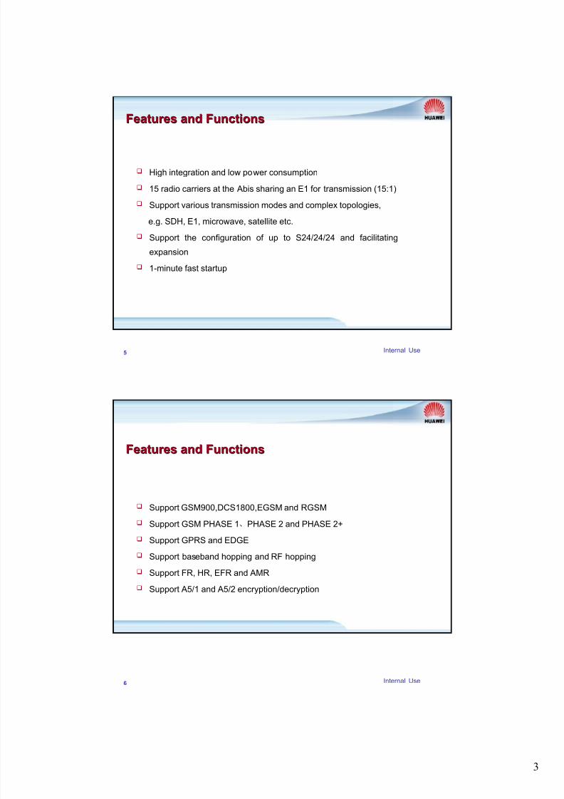
TRX Module StructureTRX Module Structure
Transmitter
DBUS
TBUS
SCP CUI
Clock processing part
TBPU
DSP
FH_BUS
TDP
RCU
RPU
Receiver
Diversity
receiver
CBUS
TBPU:TRX Baseband signal Processing Unit RPU:RF signal Processing Unit
SCP: Signaling Processing Unit DSP: Digital Signal Processing Unit CUI: Carrier Unit Interface
TDP: Transmitter Driver and PLL Unit PAU: Power Amplifier Unit RCU: Receiving Unit
DBUS: Data Bus CBUS: Control Bus TBUS: Timing Bus FH_BUS: Frequency Hopping Bus
24 Internal Use
Output Power of TRXOutput Power of TRX
Normal: 40W(46dBm) or 60W(48dBm)
EDGE TRX: GMSK: 60W, 8PSK: 40W

8/10/2019 GSM BTS312 Hardware Structure ISSUE4.0
http://slidepdf.com/reader/full/gsm-bts312-hardware-structure-issue40 13/23
13
25 Internal Use
When the standing wave ratio at the power amplifier output port
exceeds 1.5, it reports standing wave alarm to the baseband unit
When the temperature of the power amplifier exceeds 85℃, the
power amplifier unit reports the over-temperature alarm via thebaseband unit, and automatically turns off the power amplifier
Over standing wave alarm
Over-temperature alarm
Alarms of TRXAlarms of TRX
26 Internal Use
Indicators on TRXIndicators on TRX
Off On: Alarm
Off: No alarm
Alarm
Indicator RedFAIL
Flash
Flash(0.5Hz):
Normal
On or Off:
Abnormal
DSP Running
StateGreenRDP
Flash
Flash(0.5Hz):
Normal
On or Off: Abnormal
SCP Running
State
GreenRCP
OnOn: Normal
Off: AbnormalPower GreenPWR
Normal
StateExplanationMeaningColor
Indicator
Name
TX OUT
PW R
RCP
RDP
FAIL
RST
MMI
RXA IN
RXB IN
TRX

8/10/2019 GSM BTS312 Hardware Structure ISSUE4.0
http://slidepdf.com/reader/full/gsm-bts312-hardware-structure-issue40 14/23
14
27 Internal Use
CDUCDU
Combine and filter transmitted signals
Filter ,amplify and distribute received signals
Provide power for the tower-top amplifier
Alarm detection
Functions of CDUFunctions of CDU
28 Internal Use
CDU StructureCDU Structure
Combiner
Divider
Divider
Duplexer TX1
TX2
TX-COMB
TX-DUP
RX1
RX2RX3RX4
HL-out
RX2RX3RX4
RX1
HL-in
RXD-ANT
TX/RX-ANT
RXD-out
LNA
LNA Filter

8/10/2019 GSM BTS312 Hardware Structure ISSUE4.0
http://slidepdf.com/reader/full/gsm-bts312-hardware-structure-issue40 15/23
15
29 Internal Use
Indicators on CDUIndicators on CDU
Off
On: LNA current out
of range
Off: Normal
LNA
current
indication
RedLNA
Off
On: TTA current out
of range
Off: Normal
TTA
current
indication
RedTTA
Off
On: VSWR is greater
than 2.5
Off: Normal
Standing
wave ratio
alarm
RedVSWR2
Off
On: VSWR is greater
than 1.5 and
less than 2.5
Off: Normal
Standing
wave ratio
alarm
YellowVSWR1
OnOn: Normal
Off: AbnormalPower GreenPOWER
Normal
StateExplanationMeaningColor
Indicator
Name
30 Internal Use
Rear Panel of CDURear Panel of CDU
MAIN: TTA power feeding selection knob of main receiving channel
DIVERSE: TTA power feeding selection knob of diversity receiving channel
FUSE :1.5A
mA2052053
mA1001072
mA651001
off off 0
UnitDIVERSEMAINSetting
Correspondence between knob setting and current
strength of TTA
Note: MAIN is recommended to be set at 1(100mA),and
DIVERSE to be set at 2(100mA).Other modes of setting
are not recommended

8/10/2019 GSM BTS312 Hardware Structure ISSUE4.0
http://slidepdf.com/reader/full/gsm-bts312-hardware-structure-issue40 16/23
16
31 Internal Use
Alarm DetectionAlarm Detection
VSWR (Voltage Standing Wave Ratio) monitoring: CDU Monitors the
status of antenna system. When the detected standing wave ratio
exceeds the preset threshold (1.5 or 2.5), CDU will generate
corresponding alarms
Low noise amplifier fault alarm: The signal is extracted from the
power supply current of the low noise amplifier. When the current
exceeds a certain level ,alarm signals are generated
Tower-top amplifier alarm: When there is a tower-top amplifier on
service, the CDU monitors the status of tower-top amplifier by its
working current. If the current exceeds a certain level , alarm signals
are generated
32 Internal Use
Chapter 1 Overview
Chapter 2 System Components
Chapter 3 Signal Processing
Chapter 4 Antenna and Feeder System

8/10/2019 GSM BTS312 Hardware Structure ISSUE4.0
http://slidepdf.com/reader/full/gsm-bts312-hardware-structure-issue40 17/23
17
33 Internal Use
Speech ProcessingSpeech Processing
BSC-(TDU)-TMU-DBUS-TRX-CDU-ANT-MS
DBUS
S
C
P
C
U
I
Clock process
TBPU
D
S
P
FH_BUS
TDP PAU
RCU
RPU
BSC BIU
OMU
EAC MCK TDU
CBUS
TBUS
C
D
U
34 Internal Use
OML ProcessingOML Processing
BSC-(TDU)-TMU-CBUS-TRX (or PMU,CDU)
DBUS
S
CP
C
U
I
Clock process
TBPU
D
S
P
FH_BUS
TDP PAU
RCU
RPU
BSC BIU
OMU
EAC MCK TDU
CBUS
TBUS
C
DU

8/10/2019 GSM BTS312 Hardware Structure ISSUE4.0
http://slidepdf.com/reader/full/gsm-bts312-hardware-structure-issue40 18/23
18
35 Internal Use
RSL ProcessingRSL Processing
BSC-(TDU)-TMU-DBUS-TRX
DBUS
S
C
P
C
U
I
Clock process
TBPU
D
S
P
FH_BUS
TDP PAU
RCU
RPU
BSC BIU
OMU
EAC MCK TDU
CBUS
TBUS
C
D
U
36 Internal Use
Clock ProcessingClock Processing
BSC (or External Clock) –(TDU)-TMU-TDU-TBUS-TRX
DBUS
S
C
P
C
U
I
Clock process
TBPU
D
S
P
FH_BUS
TDP PAU
RCU
RPU
BSC BIU
OMU
EAC MCK TDU
CBUS
TBUS
External synchronous clock

8/10/2019 GSM BTS312 Hardware Structure ISSUE4.0
http://slidepdf.com/reader/full/gsm-bts312-hardware-structure-issue40 19/23
19
37 Internal Use
Chapter 1 Overview
Chapter 2 System Components
Chapter 3 Signal Processing
Chapter 4 Antenna and Feeder System
38 Internal Use
Antenna and Feeder SystemAntenna and Feeder System
Antenna
TTA
Antennastand
Jumper betweenantenna and TTA
Jumper betweenTTA and feeder
Feeder
Lighteningarrester
Jumper betweenlightening arresterand cabinet
BTS312
cabinet
SWITCH BOX
FAN BOX
AIR BOX
P
S
U
P
S
U
P
S
U
P
S
U
P
S
U
P
S
U
P
M
U
T
M
U
T
E
S
T
E
U
T
E
U
C
D
U
C
D
U
T
R
X
T
R
X
T
R
X
T
R
X
C
D
U
C
D
U
T
R
X
T
R
X
T
R
X
T
R
X
C
D
U
C
D
U
TDU
FAN BOX
AIR BOX
P
S
U
P
S
U
P
S
U
P
S
U
P
S
U
P
S
U
P
M
U
T
R
X
T
R
X
T
R
X
T
R
X

8/10/2019 GSM BTS312 Hardware Structure ISSUE4.0
http://slidepdf.com/reader/full/gsm-bts312-hardware-structure-issue40 20/23
20
39 Internal Use
S1/1/1S1/1/1
TX OUT
RXA
RXB
DUP
1:4
1:4
TX/RX ANT
TX
RX
HL OUT
HL IN
COMB
TX COMB
TX DUP
RXD OUT
RXD ANT
(RXB)
(TX/RXA)
40 Internal Use
S2/2/2S2/2/2
TX OUT
RXA
RXB
DUP
1:4
1:4
TX/RX ANT
TX OUT
RXA
RXB
TX
RX
HL OUT
HL IN
COMB
TX COMB
TX DUP
RXD OUT
RXD ANT
(RXB)
(TX/RXA)

8/10/2019 GSM BTS312 Hardware Structure ISSUE4.0
http://slidepdf.com/reader/full/gsm-bts312-hardware-structure-issue40 21/23
21
41 Internal Use
S4/4/4 2CDUS4/4/4 2CDU
Duplexer
Distributor Distributor Distributor Distributor Combiner Combiner
Duplexer
42 Internal Use
Lightning Arrester is used to
prevent the equipment from
being damaged by the
lightening current inducted
by the core line of the feeder
f eeder
jumper
Lightning Arrester Lightning Arrester
Lightning Arrester

8/10/2019 GSM BTS312 Hardware Structure ISSUE4.0
http://slidepdf.com/reader/full/gsm-bts312-hardware-structure-issue40 22/23
22
43 Internal Use
Types of Main Feeder Types of Main Feeder
7/8 inch
Cable loss=0.043dB/m
5/4 inch
Cable loss=0.032dB/m
1/2 inch jumper
Cable loss=0.11dB/m
Used between the antenna and the main feeder
Between the antenna and the tower-top amplifier Between the cabinet and the lightning arrester
44 Internal Use
Antenna PatternAntenna Pattern
The antenna pattern describes the radiating abilities of antennas in all
directions
360¡
Omni Antenna Directional antenna
120¡ 90¡ 65¡ ã

8/10/2019 GSM BTS312 Hardware Structure ISSUE4.0
http://slidepdf.com/reader/full/gsm-bts312-hardware-structure-issue40 23/23
45 Internal Use
PolarizationPolarization
Two main types of polarization
Vertical polarization
Horizontal polarization
The types of antenna divided by polarization
Single polarized antenna
Vertical polarization for GSM
One port for one feeder
Dual polarized antenna
+45 degree and -45 degree
Two ports for two feeders
Huawei Confidential. All Rights Reserved