GSM Based Patient Monitoring System Using …...GSM Based Patient Monitoring System Using Biomedical...
37
GSM Based Patient Monitoring System Using Biomedical Sensors By Debojit Mondal – 11705514013 Ashutosh Kumar Ray – 11705514011 MD. Sajid Alam – 11705514019 Guided By: Mr. Debabrata Bhattacharya Assistant Professor Applied Electronics & Instrumentation Engineering RCC Institute of Information Technology Project submitted in partial fulfillment of the Degree of B. Tech in Applied Electronics & Instrumentation Engineering under Maulana Abul Kalam Azad University of Technology DEPARTMENT OF APPLIED ELECTRONICS & INSTRUMENTATION ENGINEERING, RCC INSTITUTE OF INFORMATION TECHNOLOGY, CANAL SOUTH ROAD, BELIAGHATA, KOLKATA – 700015, May 2018
Transcript of GSM Based Patient Monitoring System Using …...GSM Based Patient Monitoring System Using Biomedical...

GSM Based Patient Monitoring System
Using Biomedical Sensors
By
Debojit Mondal – 11705514013
Ashutosh Kumar Ray – 11705514011
MD. Sajid Alam – 11705514019
Guided By:
Mr. Debabrata Bhattacharya
Assistant Professor
Applied Electronics & Instrumentation Engineering
RCC Institute of Information Technology
Project submitted in partial fulfillment of
the Degree of B. Tech in Applied
Electronics & Instrumentation Engineering
under Maulana Abul Kalam Azad
University of Technology
DEPARTMENT OF APPLIED ELECTRONICS &
INSTRUMENTATION ENGINEERING, RCC INSTITUTE OF
INFORMATION TECHNOLOGY, CANAL SOUTH ROAD,
BELIAGHATA, KOLKATA – 700015,
May 2018

ACKNOWLEDGEMENT
It is a great privilege for us to express our profound gratitude to our respected
teacher Mr. Debabrata Bhattacharya, Applied Electronics & Instrumentation
Engineering, RCC Institute of Information Technology, for his constant
guidance, valuable suggestions, supervision and inspiration throughout the
course work without which it would have been difficult to complete the work
within scheduled time.
We would like to express our gratitude towards Other Faculty Member for
their kind co-operation and encouragement which helped me in completion of
this project.
We are also indebted to the Head of the Department, Applied Electronics &
Instrumentation Engineering, RCC Institute of Information Technology for
permitting us to pursue the project.
We would like to take this opportunity to thank all the respected teachers of this
department for being a perennial source of inspiration and showing the right
path at the time of necessity.
Debojit Mondal – (11705514013) ………………………
Ashutosh Kumar Ray – (11705514011) ………………………
MD. Sajid Alam – (11705514019) ………………………

CERTIFICATE OF APPROVAL
The project report titled “GSM Based Patient Monitoring System Using Biomedical Sensors
” prepared by Debojit Mondal , 11705514013 :; Ashutosh Kumar Ray , 11705514011:;
MD. Sajid Alam , 11705514019 is hereby approved and certified as a creditable study in
technological subjects performed in a way sufficient for its acceptance for partial fulfilment
of the award of the degree for which it is submitted.
It is to be understood that by this approval, the undersigned do not, necessarily endorse or
approve any statement made, opinion expressed or conclusion drawn therein, but approve the
project only for the purpose for which it is submitted.
--------------------------------- ---------------------------------
Mr. Debabrata Bhattacharya Mr. Kalyan Biswas
Assistant Professor Assistant Professor
[Supervisor] [Head of the Department]
Dept. of AEIE Dept. of AEIE
RCCIIT,KOLKATA RCCIIT, KOLKATA
......………………………………
......………………………………
[Examiner]

RECOMMENDATION
I hereby recommend that the project report titled “GSM Based Patient Monitoring System
Using Biomedical Sensors” prepared by Debojit Mondal , 11705514013 :; Ashutosh Kumar
Ray , 11705514011:; MD. Sajid Alam , 11705514019 be accepted in partial fulfillment of the
requirement for the award of the Degree of Bachelor of Technology in Applied Electronics &
Instrumentation Engineering, RCC Institute of Information Technology.
--------------------------------- ---------------------------------
Mr. Debabrata Bhattacharya Mr. Kalyan Biswas
Assistant Professor Assistant Professor
[Supervisor] [Head of the Department]
Dept. of AEIE Dept. of AEIE
RCCIIT,KOLKATA RCCIIT, KOLKATA
......………………………………
......………………………………
[Examiner]
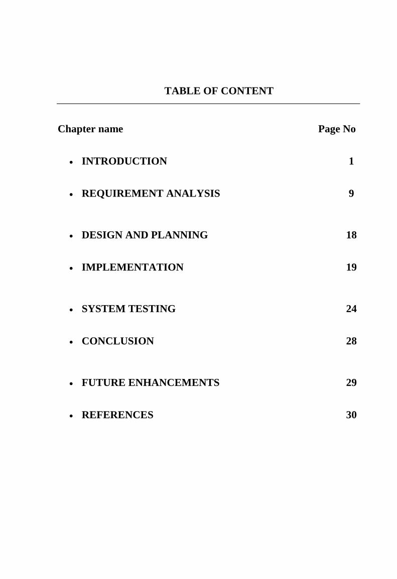
TABLE OF CONTENT
Chapter name Page No
INTRODUCTION 1
REQUIREMENT ANALYSIS 9
DESIGN AND PLANNING 18
IMPLEMENTATION 19
SYSTEM TESTING 24
CONCLUSION 28
FUTURE ENHANCEMENTS 29
REFERENCES 30

List of Figures Page No
Fig 1.5 :- Block diagram for proposed system 7
Fig. 2.1.1 :- Real Arduino UNO board 10
Fig. 2.1.2 :- Pin diagram of IC LM35 12
Fig. 2.1.3 :- GSM Modem 13
Fig. 2.1.4 :- Pulse Sensor 16
Fig. 3.2 :- Data flow diagram 18
Fig 4.1 :- Circuit diagram of temperature monitoring and controlling system 20
Fig. 5.3.2 :- Output Text SMS 27
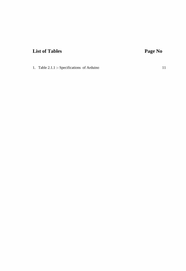
List of Tables Page No
1. Table 2.1.1 :- Specifications of Arduino 11

GSM Based Patient Monitoring System Using Biomedical Sensors
1 | P a g e
CHAPTER – 1
INTRODUCTION
1.1 Introduction and Motivation
Now Recently Wireless Sensor Networks (WSN) play a vital role in the research,
technological community hence resulting in the development of various high-performance
smart sensing system. Many new research is focused at improving quality of human life in
terms of health by designing and fabricating sensors which are either in direct contact with
the human body (invasive) or indirectly (noninvasive) in contact. Health monitoring is an
informal, non-statutory method of surveying our workforce for symptoms of ill health,
including lower back pain. This type of occupational health management system can enable
us, as an employer, to be aware of health problems and intervene to prevent problems being
caused or made worse by work activities. Another important role of health monitoring is to
give feedback into a system that reviews the current control methods in place. In addition,
there are specific regulations dealing with manual handling and whole body vibration in the
workplace. To ensure we are complying with our duties under these regulations we should
refer to HSE (health system engineering) guidance, if manual handling or whole body
vibration are risks in our workplace. Whole body vibration is particularly prevalent in those
that drive industrial and parameters and the sampled parameters are wireless.
1.1.1 Importance of biomedical engineering
The development of biomedical engineering is responsible for improving healthcare
diagnosis, monitoring and therapy. The novel idea behind Health line is to provide quality
health service to one and all. The idea is driven by the vision of a cable free biomedical
monitoring system. On body sensors monitor the vital parameters (blood pressure, ECG,
temperature and heart beat rate) and transmits the data to doctor’s end via wireless
communication network. Periodic health monitoring (or preventative care) allows people to
discover and treat health problems early, before they have consequences. Especially for risk

GSM Based Patient Monitoring System Using Biomedical Sensors
2 | P a g e
patients and long term applications, such a technology offers more freedom, comfort, and
opportunities in clinical monitoring.
1.1.2 Use of vital signals in health analysis
Chronic diseases have a significant influence on healthcare where cost of curing chance of
attack is common among people. Changes in demographic structure and lack of health and
social care personnel force us to study new innovations, which could over a relief to these
challenges. Elderly people have to make frequent visits to their doctor to get their vital signs
measured. Regular monitoring of vital signs is essential as they are primary indicators of an
individual's physical wellbeing.
These vital signs include,
a. Pulse rate
b. Blood pressure
c. Body temperature
The goal is to develop a low cost, low power, reliable, non-intrusive, and non-invasive vital
signs monitor which collect different type of body and the sampled parameters are wireless.
sensing and data conditioning system to acquire accurate heart rate, ECG, blood pressure, and
body temperature readings. After processing of data we have to find a proper method of
transmission and signal display. Remote patient monitoring (RPM) is a technology to enable
monitoring of patients outside of conventional clinical settings (e.g. in the home), which may
increase access to care and decrease healthcare delivery costs.
1.1.3 Remote Patient Monitoring
Incorporating RPM in chronic disease management can significantly improve an individual’s
quality of life. It allows patients to maintain independence, prevent complications, and
minimize personal costs. RPM facilitates these goals by delivering care right to the home. In
addition, patients and their family members feel comfort knowing that they are being
monitored and will be supported if a problem arises. This is particularly important when
patients are managing complex self-care processes such as home hemodialysis. Physiological
data such as blood pressure and subjective patient data are collected by sensors on peripheral
devices. Examples of peripheral devices are: blood pressure cuff, pulse ox meter, and
glucometer. The data are transmitted to healthcare providers or third parties via wireless
telecommunication devices. The data are evaluated for potential problems by a healthcare
professional or via a clinical decision support algorithm, and patient, caregivers, and health
providers are immediately alerted if a problem is detected. As a result, timely intervention

GSM Based Patient Monitoring System Using Biomedical Sensors
3 | P a g e
ensures positive patient outcomes. The newer applications also provide education, test and
medication reminder alerts, and a means of communication between the patient and the
provider.
1.1.4 Challenges in ICU
The intensive care unit (ICU) is one of the major components of the current health care
system. The advances in supportive care and monitoring resulted in significant improvements
in the care of surgical and clinical patients. Nowadays aggressive surgical therapies as well as
transplantation are made safer by the monitoring in a closed environment, the surgical ICU,
in the post-operative period. Several measures of ICU performance have been proposed in the
past 30 years. It is intuitive, and correct, to assume that ICU mortality may be a useful marker
of quality. The complex task of collecting and analyzing data on performance measures are
made easier when clinical information systems are available. Although several clinical
information systems focus on important aspects as computerized physician order entry
systems and individual patient tracking information, few have attempted to gather clinical
information generating full reports that provide a panorama of the ICU performance and
detailed data on several domains.
1.1.5 Gathering vital signals
Pulse is the rate at which our heart beats. Our pulse is usually called our heart rate, which is
the number of times our heart beats each minute (bpm). But the rhythm and strength of the
heartbeat can also be noted, as well as whether the blood vessel feels hard or soft. Changes in
our heart rate or rhythm, a weak pulse, or a hard blood vessel may be caused by heart disease
or another problem. As our heart pumps blood through our body, we can feel a pulsing in
some of the blood vessels close to the skin's surface, such as in our wrist, neck, or upper arm.
Counting our pulse rate is a simple way to find out how fast our heart is beating. The normal
core body temperature of a healthy, resting adult human being is stated to be at 98.6 degrees
Fahrenheit or 37.0 degrees Celsius. Though the body temperature measured on an individual
can vary, a healthy human body can maintain a fairly consistent body temperature that is
around the mark of 37.0 degrees Celsius. The normal range of human body temperature
varies due to an individual’s metabolism rate; the higher (faster) it is the higher the normal
body temperature or the slower the metabolic rate the lower the normal body temperature.
Other factors that might affect the body temperature of an individual may be the time of day
or the part of the body in which the temperature is measured at. The body temperature is
lower in the morning, due to the rest the body received, and higher at night after a day of

GSM Based Patient Monitoring System Using Biomedical Sensors
4 | P a g e
muscular activity and after food intake. Body temperature also varies at different parts of the
body. Oral temperatures, which are the most convenient type of temperature measurement, is
at 37.0 °C. This is the accepted standard temperature for the normal core body temperature.
Axillary temperatures are an external measurement taken in the armpit or between two folds
of skin on the body. This is the longest and most inaccurate way of measuring body
temperature, the normal temperature falls at 97.6 °F or 36.4 °C. Rectal temperatures are an
internal measurement taken in the rectum, which fall at 99.6 °F or 37.6 °C. It is the least time
consuming and most accurate type of body temperature measurement, being an internal
measurement. But it is definitely, by far, not the most comfortable method to measure the
body temperature
1.1.6 Internet of Things in health monitoring
The Internet of Things(IoT) and Smart Grid are of great importance in promoting and guiding
development of information technology and economic. At Present, the application of the IoT
develops rapidly, but due to the special requirements of some applications, the existing
technology cannot meet them very good. Much research work is doing to build IoT . Wi-Fi-
based Wireless Sensor Network(WSN) has the features of high bandwidth and rate, non-line-
transmission ability, large-scale data collection and high cost-effective, and it has the
capability of video monitoring, which cannot be realized with ZigBee. The research on Wi-
Fi-based WSN and its application has high practical significance to the development of the
Internet of Things and Smart Grid. Based on the current research work of applications in the
Internet of Things and the characteristics of Wi-Fi-based WSN, this paper discusses the
application of WiFi-based WSN in Internet of Things, which includes Smart Grid, Smart
Agriculture and Intelligent environment protection. Monitoring Systems and Sensors systems
have increased in importance over the years. However, increases in measurement points mean
increases in installation and maintenance cost. The development work of a Wi-Fi based Smart
Wireless Sensor Network for monitoring an Agricultural Environment. The system is capable
of intelligently monitoring agricultural conditions in a pre-programmed manner. The system
consists of three stations: Sensor Node, Router, and Server. The system is designed for
monitoring of the climate condition in an agricultural environment such as field or
greenhouse, the sensor station is equipped with several sensor elements such as Temperature,
humidity, light, air pressure, soil moisture and water level. In addition, investigation was
performed in order to integrate a novel planar electromagnetic sensor for nitrate detection.
The communication between the sensor node and the server is achieved via 802.11g wireless
modules. Sensors are used for measurements and for acquisition of data but they require an

GSM Based Patient Monitoring System Using Biomedical Sensors
5 | P a g e
effective data transfer mechanism to enable full-fledged applications that utilize the data they
collect Embedded systems is one of the most important, yet overlooked subjects in the
electronics world. When we think technology, mobile phones, tablets and laptops come to
mind, but the devices that actually help us in our daily lives are not talked too much about.
They’re often confused with larger or more general purpose computers, and it’s sometimes
difficult to discern between one and the other.
1.1.7 Embedded Processors used in real time
An embedded system is a computer system, made from a combination of hardware and
software that is used to perform a specific task . A lot of embedded systems are created with
time constraints in mind. In some situations, crossing time limits might not amount to much,
but in some, it may actually be a disaster. For example, if the embedded system in a car’s
braking system doesn’t strictly adhere to time, it may result in an accident. However, if a time
limit is passed on something less severe, it may just result in reduced performance. The
processors found in common personal computers (PC) are general-purpose or universal
processors. They are complex in design because these processors provide a full scale of
features and a wide spectrum of functionalities. They are designed to be suitable for a variety
of applications. On the other hand, another class of embedded processors focuses on
performance. These embedded processors are powerful and packed with advanced chip-
design technologies, such as advanced pipeline and parallel processing architecture. These
processors are designed to satisfy those applications with intensive computing requirements
not achievable with general-purpose processors. Overall, system and application speeds are
the main concerns. Data storage is the process of ensuring that research data is stored,
archived or disposed of in a safe and secure manner during and after the conclusion of a
research project. This includes the development of policies and procedures to manage data
handled electronically as well as through non-electronic means. Proper planning for data
handling can also result in efficient and economical storage, retrieval, and disposal of data. In
the case of data handled electronically, data integrity is a primary concern to ensure that
recorded data is not altered, erased, lost or accessed by unauthorized users. All the above
survey insist the need of real time health monitoring system which helps in critical
situations.
GSM Based Patient Monitoring System Using Biomedical Sensors
6 | P a g e
1.2 Existing System
Many existing system for Real Time Health Monitoring generally usesmicro-controller
ATMEL 89C51 ( µc 8051). It does the same job by using additional devices. The
microcontroller-controlled system contains essentially four parts, i.e., the process, the analog
to digital converter, the control algorithm, and the clock. The times when the measured
signals are converted to digital form are called the sampling instants; the time between
successive samplings is called the sampling period and is denoted by h. The output from the
process is a continuous time signal. The output is converted into digital form by the A – D
converter. The conversion is done at the sampling times.
1.3 Problem Associated With Existing System
Many existing system for temperature and pulse monitoring generally uses micro-controller
ATMEL 89C51 ( µc 8051). Due to using micro controller 8051 the process of making whole
device becomes not only very complex but also difficult and tedious. For operation it requires
A-D converter, external clock, microcontroller development board.
Consequently, the problems are as follows :-
a) It takes comparatively more time to process.
b) It requires additional devices for operation.
c) It requires external clock.
d) Programming for microc
ontroller 8051 is difficult
e) For programming it requires development system.
f) Circuit size becomes large.
g) PCB making becomes complex, difficult and tedious.
GSM Based Patient Monitoring System Using Biomedical Sensors
7 | P a g e
1.4 Objectives
The main objective of our project is to make health monitoring system simple and accurate
currently in our paper we are monitoring only body temperature and heart rate but we can
further expand our system by measuring various parameters like ECG, blood pressure etc.
The another objective of our research is to analyze these parameters to identify accurately the
problem to give patient better cure as soon as possible and these analyze data can wirelessly
transmit to the doctor anywhere in the world by using GSM. It is very costly to measure each
single parameter so in our design we are combining all three parameters in single device.
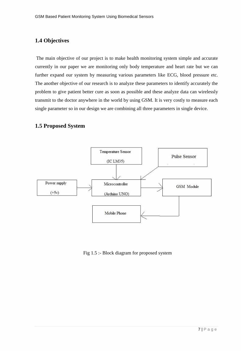
1.5 Proposed System
Fig 1.5 :- Block diagram for proposed system

GSM Based Patient Monitoring System Using Biomedical Sensors
8 | P a g e
In our project we are designing such type of device which is used for continuous monitoring
of patients in hospital. We introduce “GSM Based Patient Monitoring System Using
Biomedical Sensors”. In previous research we have seen that either the data is monitoring in
simple screen or send it by GSM, but in our project the new thing is that we can continue
monitor the Heart Rate and human body Temperature and we can also analyze his/her health
condition using ARDUINO software, which is used as the integrating platform for acquiring,
processing and transmitting data and it has provide graphical platform to analyze.1 then the
analyzed data can send to doctor or parents of patient using GSM Technology. Later we can
also introduce IOT technology to make it more flexible and more accurate that doctor can
monitor his patient condition by simple clicking on web page which is connected to
ARDUINO software using File Transfer Protocol (FTP). Overall we are introducing such
type of design which can monitor health condition and analyze the parameter and give an
alert if something going wrong and we can transmit data wirelessly anywhere by using GSM
technology. In our project we have discussed the modern visionary of healthcare industry is
to provide better healthcare to patient anytime and anywhere in the world in a more economic
and patient friendly manner. Therefore, for increasing the patient care efficacy, there arises a
need to improve the patient monitoring devices. The medical world today faces basic two
problems when it comes to patient monitoring, firstly the need of healthcare providers present
bedside the patient and secondly the patient is restricted to bed and wired to large machines.
In order to achieve better quality patient care, the above cited problems have to be solved.
This project discusses the acquisition of physiological parameters such as heart rate, body
temperature, ECG and displaying them in graphical user interface for being viewed by the
doctor.

GSM Based Patient Monitoring System Using Biomedical Sensors
9 | P a g e
CHAPTER – 2
REQUIREMENT ANALYSIS
2.1 Hardware Requirement
This project is based on both hardware and software. The hardware requirements
are as follows :-
2.1.1 Arduino
Arduino is an open-source platform used for building electronics projects. Arduino consists
of both a physical programmable circuit board (often referred to as a microcontroller) and a
piece of software, or IDE (Integrated Development Environment) that runs on our computer,
used to write and upload computer code to the physical board.
The Arduino platform has become quite popular with people just starting out with
electronics, and for good reason. Unlike most previous programmable circuit boards, the
Arduino does not need a separate piece of hardware (called a programmer) in order to load
new code onto the board – we can simply use a USB cable. Additionally, the Arduino IDE
uses a simplified version of C++, making it easier to learn to program. Finally, Arduino
provides a standard form factor that breaks out the functions of the micro-controller into a
more accessible package.
The Arduino is a microcontroller board based on the ATmega8. It has 14 digital -
input/output pins (of which 6 can be used as PWM outputs), 6 analog inputs, a
16 MHz ceramic resonator, a USB connection, a power jack, an ICSP header, and a reset
button. It contains everything needed to support the microcontroller; simply connect it to a
computer with a USB cable or power it with a AC-to-DC adapter or battery to get started.
The Uno differs from all preceding boards in that it does not use the FTDI USB-to-serial
driver chip. Instead, it features the Atmega16U2 (Atmega8U2 up to version R2) programmed
as a USB-to-serial converter. Revision 2 of the Uno board has a resistor pulling the 8U2

GSM Based Patient Monitoring System Using Biomedical Sensors
10 | P a g e
HWB line to ground, making it easier to put into DFU mode. Revision of the board has the
following new features:
1.0 pinout: added SDA and SCL pins that are near to the AREF pin and two other new
pins placed near to the RESET pin, the IOREF that allow the shields to adapt to the
voltage provided from the board. In future, shields will be compatible with both the
board that uses the AVR, which operates with 5V and with the Arduino Due that
operates with 3.3V. The second one is a not connected pin, that is reserved for future
purposes.
Stronger RESET circuit.
ATmega 16U2 replace the 8U2.
"Uno" means one in Italian and is named to mark the upcoming release of Arduino 1.0. The
Uno and version 1.0 will be the reference versions of Arduino, moving forward. The Uno is
the latest in a series of USB Arduino boards, and the reference model for the Arduino
platform.
Fig. 2.1.1 :- Real Arduino UNO board

GSM Based Patient Monitoring System Using Biomedical Sensors
11 | P a g e
Table 2.1.1 :- Specifications of Arduino
Parameters For Arduino UNO Description
Microcontroller ATmega328
Operating Voltage 5V
Input Voltage (recommended) 7-12V
Input Voltage (limits) 6-20V
Digital I/O Pins 14 (of which 6 provide PWM output)
Analog Input Pins 6
DC Current per I/O Pin 40 mA
DC Current for 3.3V Pin 50 mA
Flash Memory 32 KB (ATmega328) of which 0.5 KB used by
Bootloader
SRAM 2 KB (ATmega328)
EEPROM 1 KB (ATmega328)
Clock Speed 16 MHz
Length 68.6 mm
Width 53.4 mm
Weight 25 g
GSM Based Patient Monitoring System Using Biomedical Sensors
12 | P a g e
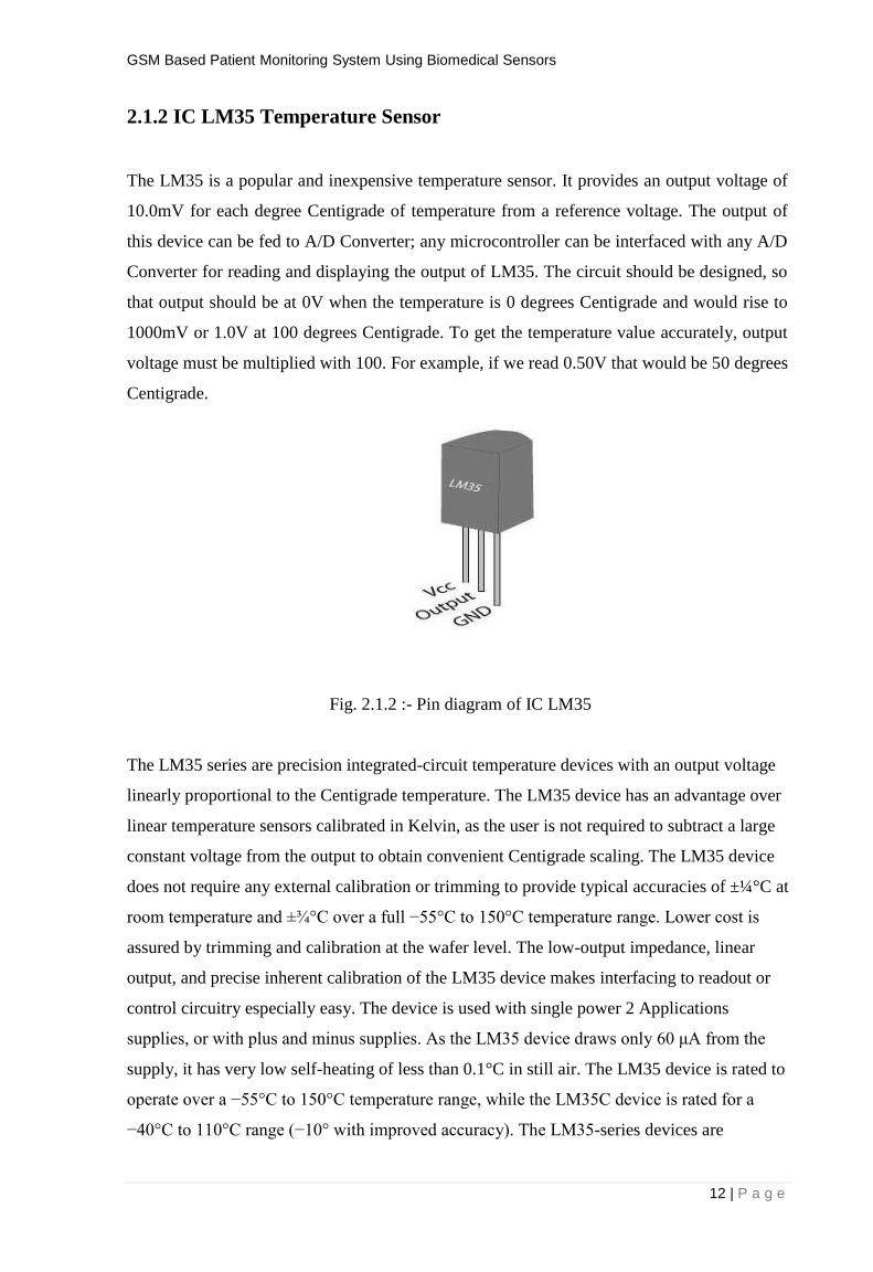
2.1.2 IC LM35 Temperature Sensor
The LM35 is a popular and inexpensive temperature sensor. It provides an output voltage of
10.0mV for each degree Centigrade of temperature from a reference voltage. The output of
this device can be fed to A/D Converter; any microcontroller can be interfaced with any A/D
Converter for reading and displaying the output of LM35. The circuit should be designed, so
that output should be at 0V when the temperature is 0 degrees Centigrade and would rise to
1000mV or 1.0V at 100 degrees Centigrade. To get the temperature value accurately, output
voltage must be multiplied with 100. For example, if we read 0.50V that would be 50 degrees
Centigrade.
Fig. 2.1.2 :- Pin diagram of IC LM35
The LM35 series are precision integrated-circuit temperature devices with an output voltage
linearly proportional to the Centigrade temperature. The LM35 device has an advantage over
linear temperature sensors calibrated in Kelvin, as the user is not required to subtract a large
constant voltage from the output to obtain convenient Centigrade scaling. The LM35 device
does not require any external calibration or trimming to provide typical accuracies of ±¼°C at
room temperature and ±¾°C over a full −55°C to 150°C temperature range. Lower cost is
assured by trimming and calibration at the wafer level. The low-output impedance, linear
output, and precise inherent calibration of the LM35 device makes interfacing to readout or
control circuitry especially easy. The device is used with single power 2 Applications
supplies, or with plus and minus supplies. As the LM35 device draws only 60 μA from the
supply, it has very low self-heating of less than 0.1°C in still air. The LM35 device is rated to
operate over a −55°C to 150°C temperature range, while the LM35C device is rated for a
−40°C to 110°C range (−10° with improved accuracy). The LM35-series devices are

GSM Based Patient Monitoring System Using Biomedical Sensors
13 | P a g e
available packaged in hermetic TO transistor packages, while the LM35C, LM35CA, and
LM35D devices are available in the plastic TO-92 transistor package.
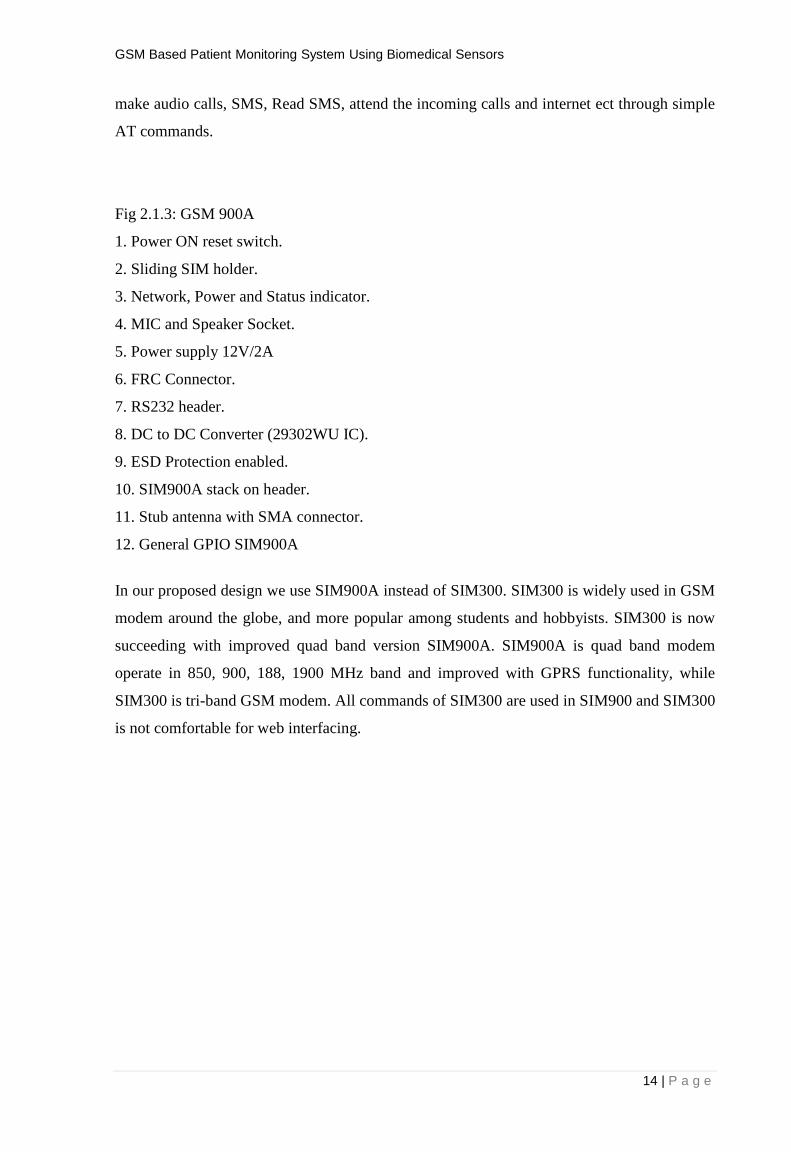
2.1.3 GSM Modem
Fig. 2.1.3 :- GSM Modem
GSM/GPRS Modem-RS232 is built with Dual Band GSM/GPRS engine- SIM900A, works
on frequencies 900/ 1800 MHz. The Modem is coming with RS232 interface, which allows
us connect PC as well as microcontroller with RS232 Chip(MAX232). The baud rate is
configurable from 9600-115200 through AT command. The GSM/GPRS Modem is having
internal TCP/IP stack to enable us to connect with internet via GPRS. It is suitable for SMS,
Voice as well as DATA transfer application in M2M interface. The onboard Regulated Power
supply allows us to connect wide range unregulated power supply . Using this modem,we can
GSM Based Patient Monitoring System Using Biomedical Sensors
14 | P a g e
make audio calls, SMS, Read SMS, attend the incoming calls and internet ect through simple
AT commands.
Fig 2.1.3: GSM 900A
1. Power ON reset switch.
2. Sliding SIM holder.
3. Network, Power and Status indicator.
4. MIC and Speaker Socket.
5. Power supply 12V/2A
6. FRC Connector.
7. RS232 header.
8. DC to DC Converter (29302WU IC).
9. ESD Protection enabled.
10. SIM900A stack on header.
11. Stub antenna with SMA connector.
12. General GPIO SIM900A
In our proposed design we use SIM900A instead of SIM300. SIM300 is widely used in GSM
modem around the globe, and more popular among students and hobbyists. SIM300 is now
succeeding with improved quad band version SIM900A. SIM900A is quad band modem
operate in 850, 900, 188, 1900 MHz band and improved with GPRS functionality, while
SIM300 is tri-band GSM modem. All commands of SIM300 are used in SIM900 and SIM300
is not comfortable for web interfacing.

15 | P a g e
2.1.4 Pulse Sensor
Optical heart-rate monitors are easy to understand in theory. If we’ve ever shined a flashlight
through our finger tips and seen our heart-beat pulse (a thing most kids have done) we have a
good handle on the theory of optical heart-rate pulse sensors.
In an optical heart-rate pulse sensor, light is shot into a fingertip or ear lobe. The light either
bounces back to a light sensor, or gets absorbed by blood cells.
As we continue to shine light (into say a fingertip) and take light sensor readings, we quickly
start to get a heart-beat pulse reading.
The theory is easy to understand. In practice, it hard to master DIY optical heart-rate sensors, or
get them operational at all. There are many tutorials online and in publications describing how
to make DIY heart-rate sensors. Through our own personal interests, we’ve tried to follow
online guides but have generally failed or had unsatisfactory results. As professors, year after
year, we see our students attempt to follow these published guides and also either fail in getting
anything to work, or get poor results. It could very well be human/user-error on our parts. But
from our view, making an optical pulse sensor is easier said than done.
So, we set out to make our own optical heart-rate pulse senor that can be used in our own
creative projects and also available to students, makers, game developers, mobile developers,
artists, athletic trainers etc….
We had three goals for our Sensor:
1) It had to actually work and be “plug and play” into Arduino (or other microcontroller).
2) It should be super small and easy to place (sew, glue, clip) into wearables, sports, arts, or
gaming application.
3) It could be used as a teaching aid for instruction on working with sensors, data visualization,
and bio-feedback.

GSM Based Patient Monitoring System Using Biomedical Sensors
16 | P a g e
Over a few months we tested a gaggle of optical sensors and LED colors and found that it was
not as easy as many suspect to get reliable heart-rate data through optical means. We could
get basic, gross, short-term data, but reliable readings assuming real-world scenarios and real-
world user interaction is key. After more experimentation and development, we started to
assemble a reliable heart-rate pulse sensor. We fabricated a few test boards and continued to
iterate the design.
As we tried to “wear” the sensor, we discovered that we should make it look and feel like a 1/2
inch button. Its size allows it to clip to earlobes or fingertips easily. When we add “button
holes” to the design it can be easily sewn or attached to various garments and fashion
accessories. The final design turned into a button-sized PCB board that holds all the technology,
hit all our goals, and is very cute and accessible to a novice or expert users/developers alike.
Fig. 2.1.4 :- Pulse Sensor
2.1.5 Power Supply
A power supply is an electronic device that supplies electric energy to an electrical load. The
primary function of a power supply is to convert one form of electrical energy to another and, as
a result, power supplies are sometimes referred to as electric power converters. Some power
supplies are discrete, stand-alone devices, whereas others are built into larger devices along with
GSM Based Patient Monitoring System Using Biomedical Sensors
17 | P a g e
their loads. Here, we use 5v dc power or sometimes power is given to the circuit directly from
computer.
2.1.5 Connecting Wires
A Wire is a single usually cylindrical, flexible strand or rod of metal. Wires are used
to bear mechanical loads or electric and telecommunication signals. Wire is formed by
drawing the metal through a hole in a die or draw plate.
2.2 Software Requirement
As explained earlier our project requires two-part hardware and software. Hardware parts are
explained above and software requires as follows:-
2.2.1 Arduino IDE
The open-source Arduino Software (IDE) makes it easy to write code and upload it to the board.
It runs on Windows, Mac OS X, and Linux. The environment is written in Java and based on
Processing and other open-source software. This software can be used with any Arduino board.
The Arduino development environment contains a text editor for writing code, a message area, a
text console, a toolbar with buttons for common functions, and a series of menus. It connects to
the Arduino hardware to upload programs and communicate with them.
Software written using Arduino are called sketches. These sketches are written in the
text editor. Sketches are saved with the file extension .ino. It has features for cutting/pasting
and for searching/replacing text. The message area gives feedback while saving and exporting
and also displays errors. The console displays text output by the Arduino environment
including complete error messages and other information. The bottom right-hand corner of
the window displays the current board and serial port. The toolbar buttons allow us to verify
and upload programs, create, open, and save sketches, and open the serial monitor.
GSM Based Patient Monitoring System Using Biomedical Sensors
18 | P a g e
CHAPTER – 3
DESIGN AND PLANNING
3.1 Process Model
In this section we design structure of the system before implementation of circuit. we use
advanced microcontroller called Arduino (ATmega8). It has in built with many components like
analog to digital converter, clock of 16 MHz, shift registers.
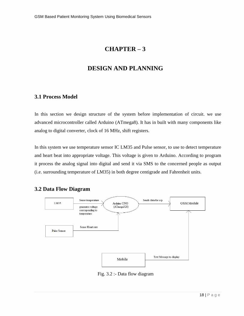
In this system we use temperature sensor IC LM35 and Pulse sensor, to use to detect temperature
and heart beat into appropriate voltage. This voltage is given to Arduino. According to program
it process the analog signal into digital and send it via SMS to the concerned people as output
(i.e. surrounding temperature of LM35) in both degree centigrade and Fahrenheit units.
3.2 Data Flow Diagram
Fig. 3.2 :- Data flow diagram
GSM Based Patient Monitoring System Using Biomedical Sensors
19 | P a g e
CHAPTER – 4
IMPLEMENTATION
4.1 Hardware Implementation
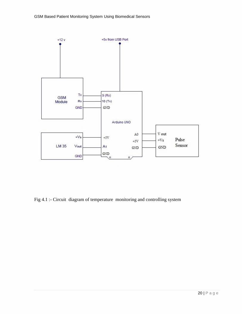
In this section we design our project Real Time Health Monitoring System using Arduino and
with the help of temperature sensor IC LM35 and pulse sensor . The signals sensed from the
patients is millivolt but the sensors volt will be 5v sensors will have the amplifiers the sensed
signals is amplified and it won’t cause harm to human health .then the signals are send to the
Arduino . Here we use Arduino (ATmega8) as a controller. This signal is given to the Analog
port (A0) and (A1) of the Arduino UNO. Arduino UNO reads analog input and converts this
analog voltage into digital bits form using inbuilt A to D converterIt converts analog voltage
level in any number between 0 to 1023. It use 10 bits for processing. This is given to the
ATmega328 microcontroller , it then process the digital data into the respective degree
centigrade for temperature and to BHP for the heart rate. Using GSM module the results will be
continuously transmit to medical officials and the data will be stored directly to the database.
GSM Based Patient Monitoring System Using Biomedical Sensors
20 | P a g e
Fig 4.1 :- Circuit diagram of temperature monitoring and controlling system

GSM Based Patient Monitoring System Using Biomedical Sensors
21 | P a g e
4.2 Software Implementation
For software implementation we require a software Arduino IDE. This software
enables us to load the program in Arduino board. Information about Arduino IDE is given in
section 2.2.1.
4.2.2 Source Code
#define USE_ARDUINO_INTERRUPTS true // Set-up low-level interrupts for most acurate
BPM math.
#include <PulseSensorPlayground.h> // Includes the PulseSensorPlayground Library.
// Variables
const int PulseWire = 0; // PulseSensor PURPLE WIRE connected to ANALOG PIN 0
const int LED13 = 13; // The on-board Arduino LED, close to PIN 13.
int Threshold = 550; // Determine which Signal to "count as a beat" and which to ignore.
#include <SoftwareSerial.h>
int val;
int tempPin = 1;
SoftwareSerial mySerial(9, 10);
// Use the "Gettting Started Project" to fine-tune Threshold Value beyond default setting.
// Otherwise leave the default "550" value.
PulseSensorPlayground pulseSensor; // Creates an instance of the PulseSensorPlayground object
called "pulseSensor"
void setup() {
GSM Based Patient Monitoring System Using Biomedical Sensors
22 | P a g e
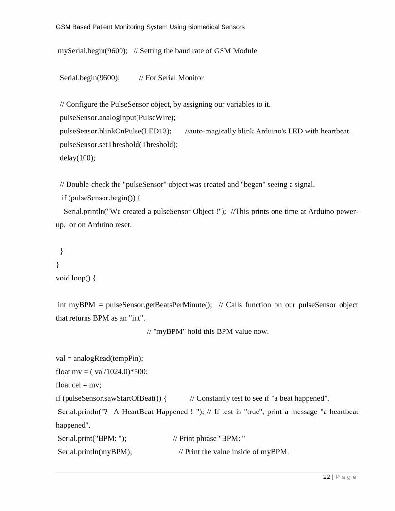
mySerial.begin(9600); // Setting the baud rate of GSM Module
Serial.begin(9600); // For Serial Monitor
// Configure the PulseSensor object, by assigning our variables to it.
pulseSensor.analogInput(PulseWire);
pulseSensor.blinkOnPulse(LED13); //auto-magically blink Arduino's LED with heartbeat.
pulseSensor.setThreshold(Threshold);
delay(100);
// Double-check the "pulseSensor" object was created and "began" seeing a signal.
if (pulseSensor.begin()) {
Serial.println("We created a pulseSensor Object !"); //This prints one time at Arduino power-
up, or on Arduino reset.
}
}
void loop() {
int myBPM = pulseSensor.getBeatsPerMinute(); // Calls function on our pulseSensor object
that returns BPM as an "int".
// "myBPM" hold this BPM value now.
val = analogRead(tempPin);
float mv = ( val/1024.0)*500;
float cel = mv;
if (pulseSensor.sawStartOfBeat()) { // Constantly test to see if "a beat happened".
Serial.println("? A HeartBeat Happened ! "); // If test is "true", print a message "a heartbeat
happened".
Serial.print("BPM: "); // Print phrase "BPM: "
Serial.println(myBPM); // Print the value inside of myBPM.

GSM Based Patient Monitoring System Using Biomedical Sensors
23 | P a g e
Serial.print("TEMPRATURE = ");
Serial.print(cel);
Serial.print("*C");
Serial.println();
mySerial.println("AT+CMGF=1"); //Sets the GSM Module in Text Mode
delay(1000); // Delay of 1000 milli seconds or 1 second
mySerial.println("AT+CMGS=\"+919674145664\"\r"); // Replace x with mobile number
delay(1000)
mySerial.println(" A HeartBeat Happened ! ");// The SMS text us want to send
mySerial.print(myBPM);
mySerial.println("temperature in celsius ");// The SMS text us want to send
mySerial.print(cel);
delay(100);
mySerial.println((char)26);// ASCII code of CTRL+Z
delay(1000);
}
delay(20); // considered best practice in a simple sketch.
}

GSM Based Patient Monitoring System Using Biomedical Sensors
24 | P a g e
CHAPTER – 5
SYSTEM TESTING
5.1 Test Approach
The project “GSM Based Patient Monitoring System Using Biomedical Sensors” is made as
explained in above chapters. It is necessary to check the system is working properly or not. It can
be tested in two methods. The system should display the current temperature and pulse rate. The
system should also send text messages to the concerned person or doctor using the GSM Module.
5.2 Test Plan
For testing the project, we make two parts. First part is used to check the program, in this step we
check the program is working properly or not. It is done by using Arduino IDE. Second part is
used to check hardware component like LM35 and Pulse sensor.
5.2.1 Features To Be Tested
After building the whole circuit we test it, testing procedure is given in section 5.3.3.
This project should satisfy some features. Features to be tested as follows:-
a) LM35 should detect temperature properly.
b) Pulse Sensor to detect Pulse.
c) Arduino should give required (according to program) outputs GSM Module.
d) GSM Module should send message to the given Mobile Number.
GSM Based Patient Monitoring System Using Biomedical Sensors
25 | P a g e
5.2.2 Testing Tools And Environment
For testing of the project we require some tools, like to test Arduino program we
require a software called Arduino IDE using this we can check the program that program is
working properly or not. For hardware checking we require power supply and proper range of
temperature.
5.3 Test Cases
In this section we discuss about the inputs, expected output, testing procedure.
Testing tools required for the circuit is explained above.
5.3.1 Inputs
The project requires three inputs. The inputs are as follows :-
a) Power supply:-
Power supply is the basic need of any electronic circuit. Here we use 5v dc battery to give
power Arduino and sometimes we can give power directly from the computer.
b) Temperature:-
It uses Body temperature as input.
c) Pulse :-

GSM Based Patient Monitoring System Using Biomedical Sensors
26 | P a g e
Pulse Sensor fits over a fingertip and uses the amount of infrared light reflected by the blood
circulating inside to do just that. ... When the heart pumps, blood pressure rises sharply, and so
does the amount of infrared light from the emitter that gets reflected back to the detector.
5.3.2 Expected Output
Result of our project work is that the human body parameter like body temperature or heart rate
is very sensitive parameter if any physical or non-physical or mental change occur to human then
it rapidly changes its value. The standard value of body temperature is 37 Degree Centigrade and
heart rate is 72 bit/second. In our proposed design the new thing we add is we are combining two
parameter in single device also we analyze the data in Arduino IDE that is main part of our
project and the analyzed data is send to the doctor using GSM. The primary objective of our
research work to reduce the cost, manpower and the time to send the information, and make
analysis as simple as possible.

GSM Based Patient Monitoring System Using Biomedical Sensors
27 | P a g e
Fig. 5.3.2 :- Output Text SMS

GSM Based Patient Monitoring System Using Biomedical Sensors
28 | P a g e
CHAPTER – 6
CONCLUSION
6.1 Conclusion
The progress in bio medical engineering, science and technology paved way for new inventions
and technologies. As we are moving towards miniaturization, handy electronic components are
in need. New products and new technology are being invented. ARDUINO was found to be more
compact, user friendly and less complex, which could readily be used in order to perform several
tedious and repetitive tasks. Simulation is performed using Arduino software by placing
appropriate sensors like temperature and heart beat rate for sensing the health condition and the
results are analyzed under normal conditions and abnormality conditions.

GSM Based Patient Monitoring System Using Biomedical Sensors
29 | P a g e
CHAPTER – 7
FUTURE ENHANCEMENTS
This project can be further enhanced by sensing and displaying other vital statistics of a patient
like ECG, blood pressure, glucose level etc. the other thing which is to add is presently we are
monitoring the data in Arduino IDE in future we can monitor data in web page using internet of
thing technology.
In future, a portable health monitoring system can be designed using Arduino.
GSM Based Patient Monitoring System Using Biomedical Sensors
30 | P a g e
CHAPTER – 8
REFERENCES
[1] Mr. Bhavin Mehta, Ms. Divya rengarajan, Mr. Ankit Prasad “Real time patient Tele-
monitoring system using Labview” International Journal of science & engineering
research , volume 3, issue 4, April 2002.
[2] Manju babu, roshna rose raju, sunil Sylvester, teenu mary Mathew, k m abubekar, “Real
time patient monitoring system using labview”, international journal of advanced
research in computer and communication engineering, volume 5, issue 3,march 2016.
[3] M priya, M. Kathiresh, “Wireless patient health monitoring system using labview”,
international journal of emerging technology in computer science and electronics
(IJETCSE) ISSN: 0976-1353 volume 22 issue 2, may 2016.
[4] M.P. Nirmala, Rampriya mahendra, ”Home based wireless health monitoring system”,
international journal of advanced research in electrical electronics and instrumentation
engineering, vol.3, issue 11, November 2014.
[5] Gunalan .M.C, Satheesh.A, “, Implementation of Wireless Patient Body Monitoring
System using RTOS”, International Journal of Engineering Research and General
Science, Volume 2, Issue 6, pp.-207-208, October-November, 2014.