GSM 08.58 - Version 5.2.0 - Digital cellular ... · GSM 08.58 Version 5.2.0 July 1996 ... 62 9.3.12...
80
GSM GSM 08.58 TECHNICAL July 1996 SPECIFICATION Version 5.2.0 Source: ETSI TC-SMG Reference: TS/SMG-030858QR1 ICS: 33.060.50 Key words: Digital cellular telecommunications system, Global System for Mobile communications (GSM) Digital cellular telecommunications system (Phase 2+); Base Station Controller - Base Transceiver Station (BSC - BTS) interface; Layer 3 specification (GSM 08.58) ETSI European Telecommunications Standards Institute ETSI Secretariat Postal address: F-06921 Sophia Antipolis CEDEX - FRANCE Office address: 650 Route des Lucioles - Sophia Antipolis - Valbonne - FRANCE X.400: c=fr, a=atlas, p=etsi, s=secretariat - Internet: [email protected] Tel.: +33 92 94 42 00 - Fax: +33 93 65 47 16 Copyright Notification: No part may be reproduced except as authorized by written permission. The copyright and the foregoing restriction extend to reproduction in all media. © European Telecommunications Standards Institute 1996. All rights reserved.
Transcript of GSM 08.58 - Version 5.2.0 - Digital cellular ... · GSM 08.58 Version 5.2.0 July 1996 ... 62 9.3.12...

GSM GSM 08.58
TECHNICAL July 1996
SPECIFICATION Version 5.2.0
Source: ETSI TC-SMG Reference: TS/SMG-030858QR1
ICS: 33.060.50
Key words: Digital cellular telecommunications system, Global System for Mobile communications (GSM)
Digital cellular telecommunications system (Phase 2+);
Base Station Controller - Base Transceiver Station
(BSC - BTS) interface;
Layer 3 specification
(GSM 08.58)
ETSI
European Telecommunications Standards Institute
ETSI Secretariat
Postal address: F-06921 Sophia Antipolis CEDEX - FRANCEOffice address: 650 Route des Lucioles - Sophia Antipolis - Valbonne - FRANCEX.400: c=fr, a=atlas, p=etsi, s=secretariat - Internet: [email protected]
Tel.: +33 92 94 42 00 - Fax: +33 93 65 47 16
Copyright Notification: No part may be reproduced except as authorized by written permission. The copyright and theforegoing restriction extend to reproduction in all media.
© European Telecommunications Standards Institute 1996. All rights reserved.

Page 2GSM 08.58 Version 5.2.0 July 1996
Whilst every care has been taken in the preparation and publication of this document, errors in content,typographical or otherwise, may occur. If you have comments concerning its accuracy, please write to"ETSI Editing and Committee Support Dept." at the address shown on the title page.

Page 3GSM 08.58 Version 5.2.0 July 1996
Contents
Foreword ...........................................................................................................................................7
1 Scope.......................................................................................................................................91.1 Normative references...................................................................................................91.2 Abbreviations ............................................................................................................10
2 Protocol model ........................................................................................................................10
3 Radio Link Layer Management Procedures................................................................................123.1 Link establishment indication.......................................................................................123.2 Link establishment request .........................................................................................123.3 Link release indication................................................................................................123.4 Link release request ..................................................................................................133.5 Transmission of a transparent L3-Message in acknowledged mode...............................133.6 Reception of a transparent L3-Message in acknowledged mode ...................................133.7 Transmission of a transparent L3-Message in unacknowledged mode ...........................143.8 Reception of a transparent L3-Message in unacknowledged mode................................143.9 Link error indication ...................................................................................................14
4 Dedicated channel management procedures..............................................................................144.1 Channel activation......................................................................................................14
4.1.1 Signalling Procedure ...............................................................................154.1.2 Activation for Intra-Cell Channel Change...................................................164.1.3 Activation for Asynchronous Handover......................................................164.1.4 Activation for Synchronous Handover........................................................16
4.2 Channel MODE MODIFY ...........................................................................................174.3 Handover detection....................................................................................................174.4 Start of encryption.....................................................................................................184.5 Measurement reporting..............................................................................................18
4.5.1 Basic measurement reporting ..................................................................194.5.2 Measurement pre-processing ..................................................................19
4.5.2.1 Pre-processing configuration............................................204.5.2.2 Pre-processed measurement reporting.............................20
4.6 Deactivate SACCH ....................................................................................................214.7 Radio channel release................................................................................................214.8 MS power control ......................................................................................................214.9 Transmission power control........................................................................................224.10 Connection failure......................................................................................................224.11 Physical context request ............................................................................................234.12 SACCH information modify .........................................................................................23
5 Common channel management procedures................................................................................235.1 Channel request by MS..............................................................................................235.2 Paging......................................................................................................................235.3 Delete indication........................................................................................................245.4 CCCH load indication .................................................................................................245.5 Broadcast information modify .....................................................................................245.6 Short Message Cell Broadcast ...................................................................................255.7 IMMEDIATE ASSIGNMENT.......................................................................................27
6 TRX management procedures ..................................................................................................286.1 Radio resource indication ...........................................................................................286.2 SACCH filling information modify.................................................................................286.3 Flow control ..............................................................................................................28

Page 4GSM 08.58 Version 5.2.0 July 1996
6.4 Error reporting...........................................................................................................29
7 Error handling..........................................................................................................................307.1 General ....................................................................................................................307.2 Message discriminator error.......................................................................................307.3 Message type error ...................................................................................................307.4 Message sequence error ...........................................................................................307.5 General information element errors .............................................................................307.6 Mandatory information element errors .........................................................................307.7 Optional information element errors.............................................................................317.8 Conditional information element errors.........................................................................31
8 Message formats and contents.................................................................................................318.1 Transparent messages ..............................................................................................328.2 Non-transparent messages (BSC-BTS specific messages) ...........................................328.3 Radio link layer management messages......................................................................33
8.3.1 DATA REQUEST....................................................................................338.3.2 DATA INDICATION.................................................................................348.3.3 ERROR INDICATION..............................................................................348.3.4 ESTABLISH REQUEST...........................................................................348.3.5 ESTABLISH CONFIRM ...........................................................................358.3.6 ESTABLISH INDICATION........................................................................358.3.7 RELEASE REQUEST..............................................................................358.3.8 RELEASE CONFIRM..............................................................................368.3.9 RELEASE INDICATION ..........................................................................368.3.10 UNIT DATA REQUEST............................................................................378.3.11 UNIT DATA INDICATION ........................................................................37
8.4 DEDICATED CHANNEL MANAGEMENT MESSAGES .................................................388.4.1 CHANNEL ACTIVATION..........................................................................398.4.2 CHANNEL ACTIVATION ACKNOWLEDGE...............................................408.4.3 CHANNEL ACTIVATION NEGATIVE ACKNOWLEDGE .............................408.4.4 CONNECTION FAILURE INDICATION .....................................................408.4.5 DEACTIVATE SACCH.............................................................................408.4.6 ENCRYPTION COMMAND......................................................................418.4.7 HANDOVER DETECTION .......................................................................418.4.8 MEASUREMENT RESULT ......................................................................428.4.9 MODE MODIFY .....................................................................................428.4.10 MODE MODIFY ACKNOWLEDGE ..........................................................438.4.11 MODE MODIFY NEGATIVE ACKNOWLEDGE.........................................438.4.12 PHYSICAL CONTEXT REQUEST............................................................438.4.13 PHYSICAL CONTEXT CONFIRM ............................................................448.4.14 RF CHANNEL RELEASE.........................................................................448.4.15 MS POWER CONTROL..........................................................................448.4.16 BS POWER CONTROL ..........................................................................458.4.17 PRE-PROCESS CONFIGURE.................................................................458.4.18 PRE-PROCESSED MEASUREMENT RESULT.........................................458.4.19 RF CHANNEL RELEASE ACKNOWLEDGE ..............................................458.4.20 SACCH INFO MODIFY ...........................................................................46
8.5 COMMON CHANNEL MANAGEMENT MESSAGES.....................................................468.5.1 BCCH INFORMATION ............................................................................478.5.2 CCCH LOAD INDICATION ......................................................................478.5.3 CHANNEL REQUIRED............................................................................488.5.4 DELETE INDICATION.............................................................................488.5.5 PAGING COMMAND ..............................................................................488.5.6 IMMEDIATE ASSIGN COMMAND...........................................................498.5.7 SMS BROADCAST REQUEST ................................................................498.5.8 SMS BROADCAST COMMAND ..............................................................498.5.9 CBCH LOAD INDICATION ......................................................................50
8.6 TRX MANAGEMENT MESSAGES..............................................................................508.6.1 RF RESOURCE INDICATION..................................................................51

Page 5GSM 08.58 Version 5.2.0 July 1996
8.6.2 SACCH FILLING ....................................................................................518.6.3 OVERLOAD...........................................................................................518.6.4 ERROR REPORT...................................................................................52
9 Information element codings .....................................................................................................539.1 Message discriminator...............................................................................................539.2 MESSAGE TYPE......................................................................................................549.3 Other information elements ........................................................................................55
9.3.1 Channel Number .....................................................................................569.3.2 Link Identifier..........................................................................................569.3.3 Activation Type.......................................................................................579.3.4 BS Power ..............................................................................................579.3.5 Channel Identification ..............................................................................589.3.6 Channel Mode ........................................................................................589.3.7 Encryption information.............................................................................609.3.8 Frame Number .......................................................................................619.3.9 Handover reference ................................................................................619.3.10 L1 Information ........................................................................................619.3.11 L3 Information (message name) ..............................................................629.3.12 MS Identity ............................................................................................629.3.13 MS Power..............................................................................................629.3.14 Paging Group.........................................................................................639.3.15 Paging Load...........................................................................................639.3.16 Physical Context.....................................................................................639.3.17 Access Delay .........................................................................................639.3.18 RACH Load............................................................................................649.3.19 Request Reference.................................................................................649.3.20 Release Mode........................................................................................659.3.21 Resource Information..............................................................................659.3.22 RLM Cause............................................................................................669.3.23 Starting Time..........................................................................................679.3.24 Timing Advance ......................................................................................679.3.25 Uplink Measurements..............................................................................679.3.26 Cause....................................................................................................689.3.27 Measurement result number ....................................................................729.3.28 Message Identifier..................................................................................729.3.29 SACCH Information.................................................................................729.3.30 System Info Type ...................................................................................739.3.31 MS Power Parameters ...........................................................................749.3.32 BS Power Parameters ............................................................................749.3.33 Pre-processing Parameters.....................................................................759.3.34 Pre-processed Measurements.................................................................759.3.35 Full Immediate Assign Info.......................................................................759.3.36 SMSCB Information ................................................................................769.3.37 MS Timing Offset ...................................................................................769.3.38 Erroneous Message................................................................................769.3.39 Full BCCH Information (message name) ...................................................779.3.40 Channel Needed .....................................................................................779.3.41 CB Command type .................................................................................789.3.42 SMSCB Message...................................................................................799.3.43 CBCH Load Information ..........................................................................799.3.44 SMSCB Channel Indicator .......................................................................79
History .............................................................................................................................................80

Page 6GSM 08.58 Version 5.2.0 July 1996
Blank page
Page 7GSM 08.58 Version 5.2.0 July 1996
Foreword
This Global System for Mobile communications Technical Specification (GTS) has been produced by theSpecial Mobile Group (SMG) Technical Committee (TC) of the European Telecommunications StandardsInstitute (ETSI).
This GTS specifies the general structure of layer 3 and traffic management procedures and messagesused on the A-bis interface to support signalling procedures within the digital cellular telecommunicationssystem (Phase 2/Phase 2+).
This GTS is a TC-SMG approved GSM technical specification version 5, which contains GSM Phase 2+enhancements/features to the version 4 GSM technical specification. The ETS from which this Phase 2+GTS has evolved is Phase 2 GSM ETS 300 596 Edition 4 (GSM 08.58 version 4.9.0).
GTS are produced by TC-SMG to enable the GSM Phase 2+ specifications to become publicly available,prior to submission for the formal ETSI standards approval procedure to become EuropeanTelecommunications Standards (ETS). This ensures the earliest possible access to GSM Phase 2+specifications for all Manufacturers, Network operators and implementors of the Global System for Mobilecommunications.
The contents of this GTS are subject to continuing work within TC-SMG and may change following formalTC-SMG approval. Should TC-SMG modify the contents of this GTS it will then be republished by ETSIwith an identifying change of release date and an increase in version number as follows:
Version 5.x.y
where:y the third digit is incremented when editorial only changes have been incorporated in the
specification;
x the second digit is incremented for all other types of changes, i.e. technical enhancements,corrections, updates, etc.
The specification from which this GTS has been derived was originally based on CEPT documentation,hence the presentation of this GTS may not be entirely in accordance with the ETSI rules.
Reference is made within this GTS to GSM-TSs (note).
NOTE: TC-SMG has produced documents which give the technical specifications for theimplementation of the digital cellular telecommunications system. Historically, thesedocuments have been identified as GSM Technical Specifications (GSM-TSs). TheseTSs may have subsequently become I-ETSs (Phase 1), or ETSs/ETSI TechnicalReports (ETRs) (Phase 2). TC-SMG has also produced ETSI GSM TSs which give thetechnical specifications for the implementation of Phase 2+ enhancements of the digitalcellular telecommunications system. These version 5.x.x GSM Technical Specificationsmay be referred to as GTSs.

Page 8GSM 08.58 Version 5.2.0 July 1996
Blank page

Page 9GSM 08.58 Version 5.2.0 July 1996
1 Scope
The use and general aspects of the Base Station Controller (BSC) to Base Station Transceiver (BTS)interface (the A-bis interface) are given in Technical Specification GSM 08.51.
This Global System for Mobile communications Technical Specification (GTS) specifies the generalstructure of layer 3 and traffic management procedures and messages used on the A-bis interface tosupport signalling procedures as defined in Technical Specification GSM 04.08.
Network management procedures and messages for the A-bis interface are defined in TechnicalSpecification GSM 08.59.
The functional split between BSC and BTS is defined in Technical Specification GSM 08.52. Theprocedures and messages required to support this split are defined in detail in this specification.
1.1 Normative references
This GTS incorporates by dated and undated reference, provisions from other publications. Thesenormative references are cited at the appropriate places in the text and the publications are listedhereafter. For dated references, subsequent amendments to or revisions of any of these publications applyto this GTS only when incorporated in it by amendment or revision. For undated references, the latestedition of the publication referred to applies.
[1] GSM 01.04 (ETR 100): "Digital cellular telecommunications system (Phase 2);Abbreviations and acronyms".
[2] GSM 03.20 (ETS 300 534): "Digital cellular telecommunications system(Phase 2); Security related network functions".
[3] GSM 04.04 (ETS 300 553): "Digital cellular telecommunications system(Phase 2); layer 1 General requirements".
[4] GSM 04.05 (ETS 300 554): "Digital cellular telecommunications system(Phase 2); Data Link (DL) layer General aspects".
[5] GSM 04.06 (ETS 300 555): "Digital cellular telecommunications system(Phase 2); Mobile Station - Base Station System (MS - BSS) interface Data Link(DL) layer specification".
[6] GSM 04.08 (ETS 300 557): "Digital cellular telecommunications system(Phase 2); Mobile radio interface layer 3 specification".
[7] GSM 04.12 (ETS 300 560): "Digital cellular telecommunications system(Phase 2); Short Message Service Cell Broadcast (SMSCB) support on themobile radio interface".
[8] GSM 05.02 (ETS 300 574): "Digital cellular telecommunications system(Phase 2); Multiplexing and multiple access on the radio path".
[9] GSM 05.05 (ETS 300 577): "Digital cellular telecommunications system(Phase 2); Radio transmission and reception".
[10] GSM 05.08 (ETS 300 578): "Digital cellular telecommunications system(Phase 2); Radio subsystem link control".

Page 10GSM 08.58 Version 5.2.0 July 1996
[11] GSM 05.10 (ETS 300 579): "Digital cellular telecommunications system(Phase 2); Radio subsystem synchronisation".
[12] GSM 08.06 (ETS 300 589): "Digital cellular telecommunications system(Phase 2); Signalling transport mechanism specification for the Base StationSystem - Mobile-services Switching Centre (BSS - MSC) interface".
[13] GSM 08.08 (ETS 300 590): "Digital cellular telecommunications system(Phase 2); Mobile Switching Centre - Base Station System (MSC - BSS)interface Layer 3 specification".
[14] GSM 08.51 (ETS 300 592): "Digital cellular telecommunications system(Phase 2); Base Station Controller - Base Transceiver Station (BSC - BTS)interface General aspects".
[15] GSM 08.52 (ETS 300 593): "Digital cellular telecommunications system(Phase 2); Base Station Controller - Base Transceiver Station (BSC - BTS)interface principles".
[16] GSM 08.56 (ETS 300 595): "Digital cellular telecommunications system(Phase 2); Base Station Controller - Base Transceiver Station (BSC - BTS)interface Layer 2 specification".
1.2 Abbreviations
Abbreviations used in this specification are listed in GSM 01.04.
2 Protocol model
A model for L3 can be found in figure 2.1.
L2 addressing is made to TRX (or BCF) using the TEI of LAPD. Different L2 links are used for trafficmanagement messages (RSL, Radio Signalling Link), network management messages (OML, Operation &Maintenance Link) and L2 management messages (L2ML, Layer 2 Management Link).
For traffic management, two types of signalling messages have been defined:
Transparent Messages: Messages which are forwarded by BTS without interpretation or changes.
Non-Transparent Messages: Messages which are sent only between BSC and BTS and which BTS isacting upon or which are the results of BTS actions.
In addition, the messages have been grouped into four main groups: Radio Link Layer Management,Dedicated Channel Management, Common Channel Management and TRX Management messages.
Discrimination between these types and groups is based on the Message Discriminator which is sent asthe first octet in all messages. Transparent and non-transparent messages are discriminated by atransparency flag (T-bit) in the Message Discriminator. Transparent messages are merely forwarded to L2on the radio interface.
In order to address the relevant radio channel, a Channel Number element is included to support thedistribution of messages to relevant physical channels on the TRX. A Link Identifier element supports thedistribution on logical links/channels on the radio interface (compare the DLCI element of the A interface,TS GSM 08.06).
All messages in this specification are to be transmitted on the A-bis interface using the I format of LAPD,except for MEASUREMENT RESULT which is sent in UI format.

Page 11GSM 08.58 Version 5.2.0 July 1996
Chan NoLinkdistri-bution
Other processes within BTS
Traffic ManagementProcedures(08.58)
TransparentMessages
Non-TransparentMessages
Distribution
NetworkManagementProcedures(12.21)
L2ManagementProcedures
To radiointerface
0 62 63
RSL OML L2ML
L3
L2
Figure 2.1/08.58: L3 model.

Page 12GSM 08.58 Version 5.2.0 July 1996
3 Radio Link Layer Management Procedures
This section describes procedures related to the management of a link layer connection on the radio path.
3.1 Link establishment indication
This procedure is used by BTS to indicate to BSC that a layer 2 link on the radio path has beenestablished in multi-frame mode at the initiative of an MS. BSC can use this indication to set up an SCCPconnection to MSC.
Upon reception of a SABM frame on a link on an active channel, the BTS sends an ESTablish INDicationmessage to BSC. The message contains the contents of the information field of the SABM frame ifpresent.
The procedure is used in all establishment cases, for all channels and all SAPIs.
��������06������������������%76�����������������%6&�����������������������������·�������������������·���������������ILUVW�6$%0����·�������������������·����������������������������!·����(67�,1'��������·�����������������������������·¶¶¶¶¶¶¶¶¶¶¶¶¶¶¶¶¶¶!·
3.2 Link establishment request
This procedure is used by BSC to request the establishment of a link layer connection in multi-frame modeon the radio path.
The procedure is started by BSC sending an ESTablish REQuest message to BTS. BTS then establishesthe link by sending an SABM frame. Upon reception of the acknowledgement (UA-frame) from MS, BTSsends an ESTablish CONFirm message to BSC.
In case of a failure, BTS sends a RELease INDication and an ERRor INDication message to BSC(c.f. TS GSM 04.06).
��������06������������������%76�����������������%6&�����������������������������·�������������������·�����������������������������·����(67�5(4��������·����������������6$%0���������·�¶¶¶¶¶¶¶¶¶¶¶¶¶¶¶¶¶�·�����������������������������·�������������������·�����������������8$����������·�������������������·����������������������������!·����(67�&21)�������·�����������������������������·¶¶¶¶¶¶¶¶¶¶¶¶¶¶¶¶¶¶!·�����������������������������·�������������������·
3.3 Link release indication
This procedure is used by BTS to indicate to BSC that a link layer connection on the radio path has beenreleased at the initiative of an MS.
When receiving a DISC frame on a link layer connection in multi-frame mode, BTS sends a RELeaseINDication message to BSC. (If the link layer is in idle mode, BTS will send a DM frame to MS but doesnot notify BSC.)
Collision cases are treated as specified in Technical Specification GSM 04.06.
��������06������������������%76�����������������%6&�����������������������������·�������������������·���������������ILUVW�',6&����·�������������������·����������������������������!·�������������������·�������������������8$��������·����5(/�,1'��������·�����������������������������·¶¶¶¶¶¶¶¶¶¶¶¶¶¶¶¶¶¶!·

Page 13GSM 08.58 Version 5.2.0 July 1996
3.4 Link release request
This procedure is used by BSC to request the release of a link layer connection on the radio path.
The procedure is started by BSC sending a RELease REQuest message to BTS. BTS then sends a DISCframe to MS. When it has received the acknowledgement (UA or DM frame), BTS sends a RELeaseCONFirm message to BSC.
Collision cases are treated as specified in Technical Specification GSM 04.06.
If BTS has repeated the DISC frame N200 times, BTS sends a RELease INDication and an ERRorINDication message to BSC (c.f. TS GSM 04.06).
��������06������������������%76�����������������%6&�����������������������������·�������������������·�����������������������������·����5(/�5(4��������·����������������',6&���������·�¶¶¶¶¶¶¶¶¶¶¶¶¶¶¶¶¶�·�����������������������������·�������������������·���������������8$��RU�'0�����·�������������������·����������������������������!·����5(/�&21)�������·�����������������������������·¶¶¶¶¶¶¶¶¶¶¶¶¶¶¶¶¶¶!·�����������������������������·�������������������·
3.5 Transmission of a transparent L3-Message in acknowledged mode
This procedure is used by BSC to request the sending of a L3 message to MS in acknowledged mode.
BSC sends a DATA REQuest message to BTS. The message contains the complete L3 message to besent in acknowledged mode.
��������06������������������%76�����������������%6&�����������������������������·�������������������·�����������������������������·����'$7$�5(4�������·��������������,�IUDPHV�������·�¶¶¶¶¶¶¶¶¶¶¶¶¶¶¶¶¶�·�����������������������������·�������������������·��������������55�IUDPHV������·�������������������·����������������������������!·�������������������·
3.6 Reception of a transparent L3-Message in acknowledged mode
This procedure is used by BTS to indicate the reception of a L3 message in acknowledged mode.
BTS sends a DATA INDication message to BSC. The message contains the received L3 message.
��������06������������������%76�����������������%6&�����������������������������·�������������������·��������������,�IUDPHV�������·�������������������·����������������������������!·�������������������·��������������55�IUDPHV������·�������������������·�����������������������������·����'$7$�,1'�������·�����������������������������·¶¶¶¶¶¶¶¶¶¶¶¶¶¶¶¶¶¶!·

Page 14GSM 08.58 Version 5.2.0 July 1996
3.7 Transmission of a transparent L3-Message in unacknowledged mode
This procedure is used by BSC to request the sending of a L3 message to MS in unacknowledged mode.
BSC sends a UNIT DATA REQuest message to BTS. The message contains the L3 message to be sent toMS in unacknowledged mode.
��������06������������������%76�����������������%6&�����������������������������·�������������������·�����������������������������·��81,7�'$7$�5(4����·���������������8,�IUDPH������·�¶¶¶¶¶¶¶¶¶¶¶¶¶¶¶¶¶¶·�����������������������������·�������������������·
3.8 Reception of a transparent L3-Message in unacknowledged mode
This procedure is used by BTS to indicate the reception of a L3 message in unacknowledged mode.
BTS sends a UNIT DATA INDication message to BSC. The message contains the received L3 message.
��������06������������������%76�����������������%6&�����������������������������·�������������������·���������������8,�IUDPH������·�������������������·����������������������������!·��81,7�'$7$�,1'����·�����������������������������·¶¶¶¶¶¶¶¶¶¶¶¶¶¶¶¶¶¶!·
3.9 Link error indication
This procedure is used by BTS to indicate an abnormal case such as the following.
- a protocol error as specified in Technical Specification GSM 04.06, sections 5.6.4, 5.7.3 andAnnex G;
- a link layer failure, i.e. the repetition of an I-frame N200 times without an acknowledgement;
- the repetition of an SABM or DISC frame N200 times without an acknowledgement;
- the reception of an SABM frame in multi-frame established state.
When such an event has occurred, BTS notifies BSC by sending an ERROR INDication messagecontaining the relevant cause information.
��������06������������������%76�����������������%6&�����������������������������·�������������������·���������������DEQRUPDO������·�������������������·���������������FDVH����������·���(5525�,1'�������·�����������������������������·¶¶¶¶¶¶¶¶¶¶¶¶¶¶¶¶¶¶!·
4 Dedicated channel management procedures
4.1 Channel activation
This procedure is used to activate a channel at BTS for an MS which later will be commanded to thischannel by an IMMediate ASSIGN, an ASSIGN CoMmanD, an ADDitional ASSIGNment or a HANDOverCoMmanD message.
In the handover case, the procedure is used between the target BSC and the target BTS to activate achannel for a subsequent handover from the old BTS.

Page 15GSM 08.58 Version 5.2.0 July 1996
4.1.1 Signalling Procedure
BSC determines what channel shall be used and starts up that channel at BTS by sending a CHANnelACTIVation message to the relevant TRX. This message contains the reason for the activation (immediateassignment, assignment, asynchronous/synchronous handover, additional assignment), the identification ofthe channel to be used (channel no) and a complete description of the channel (full/half rate, speech/data,coding/rate adaption, hopping sequence, encryption key etc.)
If the Encryption Information field is present, the activation is done with ciphering active. If the EncryptionInformation element is not present, activation is done without ciphering.
After activating the channel as requested, TRX responds with the CHANnel ACTIVation ACKnowledgemessage. This message contains the current frame number at BTS. The frame number is used by BSC todetermine the Starting Time parameter to be included in the following assignment message to MS.(A suitable number has to be added to current frame number to take all possible signalling delays intoaccount).
�����06���������������%76�����������������%6&����������������������·�������������������·����������������������·����&+$1�$&7,9�����·����������������������·�¶¶¶¶¶¶¶¶¶¶¶¶¶¶¶¶¶�·����������������������·�������������������·����������������������·��&+$1�$&7,9�$&.���·����������������������·¶¶¶¶¶¶¶¶¶¶¶¶¶¶¶¶¶¶!·
2Q�ROG�FKDQQHO�����������������������·�DVVLJQPHQW�WR�06��·,00HGLDWH�$66,*1�RU������������������������������������������·�$66,*1�&R0PDQ'�RU����������������������·�������������������·�$''LWLRQDO�$66,*1
If the TRX for some reason cannot activate the resource as requested by the CHANnel Activationmessage, the TRX shall return a CHANnel ACTIVation Negative ACKnowledge message with the mostappropriate cause value.
Possible cause values may be:
- O&M intervention (e.g. channel blocked),- resource not available (e.g. speech coder, encryption device),- equipment failure,- channel already activated,- etc.
%76�����������������%6&�·�������������������·�·����&+$1�$&7,9�����·�·�¶¶¶¶¶¶¶¶¶¶¶¶¶¶¶¶¶¶·�·�������������������·�·�&+$1�$&7,9�1$&.���·�·¶¶¶¶¶¶¶¶¶¶¶¶¶¶¶¶¶¶!·
In the handover case, the procedure is initiated by the target BSC when this receives the HANDOverREQuest message from MSC (or autonomously by BSC for BSC internal handover). The BSC sends aCHANnel ACTIVation message to the relevant TRX. The message contains the Handover Reference valuewhich can be used by the BTS to check the Handover Access from MS. After activation of the channelTRX responds with a CHANnel ACTIVation ACKnowledge message containing the current frame number atBTS.

Page 16GSM 08.58 Version 5.2.0 July 1996
The BSC can then determine the Starting Time parameter to be included in the HANDOver REQuestACKnowledge message to MSC (and the HANDOver CoMmanD message to MS).
��������%76�����������������%6&��������·�������������������·��������·�������������������·���+$1'2�5(4��������·�������������������·���������������������������������������������������·����&+$1�$&7,9�����·��������·�¶¶¶¶¶¶¶¶¶¶¶¶¶¶¶¶¶¶·��������·�������������������·��������·���&+$1�$&7,9�$&.��·��������·¶¶¶¶¶¶¶¶¶¶¶¶¶¶¶¶¶¶!·��������������������������������������·�������������������·�+$1'2�5(4�$&.��������·�������������������·���������������!������������������������������������RU��������·�������������������·�+$1'2�&0'�WR�06��������·�������������������·�����������������!
4.1.2 Activation for Intra -Cell Channel Change
This activation precedes the Immediate Assignment, Assignment or Additional assignment procedures. TheTiming Advance element must be included in the CHANNEL ACTIVATION message.
BTS activates the channel and starts transmission and reception on the main channel in the indicatedmode. Ciphering is started if so indicated in the encryption information.
The reception and transmission on SACCH is also started immediately.
If the BS and/or MS power elements and/or the Physical Context element are present, the reception andtransmission processes and the L1-header of SACCH are initialized accordingly.
4.1.3 Activation for Asynchronous Handover
BTS starts transmission immediately on the main channel in the indicated mode and with encryption if soindicated. If the MS Power element is present the BTS may start transmission also on the SACCH.
When receiving a correct access burst with the correct handover reference, BTS starts the normalreception process on the main channel in the indicated mode and starts receiving (and sending if notstarted earlier) on SACCH. Deciphering is started if so indicated. The handover detection proceduretowards BSC is also started.
4.1.4 Activation for Synchronous Handover
BTS starts transmission immediately on the main channel in the indicated mode and with encryption if soindicated. If the MS Power and Timing Advance element are present, BTS shall start transmission also onSACCH with the timing advance and MS power control parameters indicated. If only the MS powerelement is present the BTS may start transmission also on the SACCH.
When receiving a correct access burst with the correct handover reference, BTS starts the normalreception process on the main channel in the indicated mode, with deciphering applied if so indicated, andstarts receiving (and sending if not started earlier) on SACCH. The handover detection procedure towardsBSC is also started. Alternatively, the reception of a correctly decoded frame from the MS on the mainchannel, in the indicated mode and deciphering applied if so indicated, allows the start of sending onSACCH (if not already started) and starts the handover detection procedure towards the BSC.
NOTE: The activation for synchronous handover can be used for pseudo synchronizedhandover.

Page 17GSM 08.58 Version 5.2.0 July 1996
4.2 Channel MODE MODIFY
This procedure is used by BSC to request a change of the channel mode of an active channel.
BSC initiates the procedure by sending a MODE MODIFY message to BTS. The message contains thenew mode to be used. After having changed to the new mode, BTS responds with a MODE MODIFYACKnowledge message to BSC.
��������06������������������%76�����������������%6&�����������������������������·�������������������·�����������������������������·����02'(�02',)<����·�����������������������������·�¶¶¶¶¶¶¶¶¶¶¶¶¶¶¶¶¶�·�����������������������������·�������������������·�����������������������������·�02'(�02',)<�$&.���·�����������������������������·¶¶¶¶¶¶¶¶¶¶¶¶¶¶¶¶¶¶!·�����������������������������·�������������������·
If the TRX for some reason cannot modify the channel as requested in the MODE MODIFY message, theTRX shall return a MODE MODIFY Negative ACKnowledge message with the most appropriate causevalue.
��������06������������������%76�����������������%6&�����������������������������·�������������������·�����������������������������·����02'(�02',)<����·�����������������������������·�¶¶¶¶¶¶¶¶¶¶¶¶¶¶¶¶¶�·�����������������������������·�������������������·�����������������������������·�02'(�02',)<�1$&.��·�����������������������������·¶¶¶¶¶¶¶¶¶¶¶¶¶¶¶¶¶¶!·�����������������������������·�������������������·
4.3 Handover detection
This procedure is used between the target BTS and BSC when a handed over MS accesses the new BTS.
The procedure is initiated by BTS upon detection of an MS on a channel activated for handover asdescribed in 4.1.3 for the asynchronous handover and in 4.1.4 for synchronous handover.
In case of an asynchronous handover, BTS builds the PHYsical INFOrmation message as specified inTechnical Specification GSM 04.08, sends the message to MS in unacknowledged mode on the mainsignalling link and starts timer T3105. A HANDOver DETection message is sent to BSC. This messagecontains the measured delay of the access burst. If the timer expires before the reception of a correctlydecoded frame from MS, BTS repeats the PHYSical INFOrmation message to MS as specified inTechnical Specification GSM 04.08. If the PHYsical INFOrmation message has been repeated Ny1 timeswithout a correctly decoded frame being received from MS, the BTS shall send a CONNECTION FAILUREmessage to BSC with the cause value "handover access failure".
In case of a synchronous handover, BTS only sends a HANDOver DETection message to BSC (noPHYsical INFOrmation message sent to MS). If the handover detection is based on the detection of anhandover access burst with the correct handover reference, see 4.1.4, the measured delay of the accessburst is included in the HANDOver DETection message.
��������06������������������%76�����������������%6&�����������������������������·�������������������·��������������+$1'2�$&&(66���·�������������������·����������������������������!·�����+$1'2�'(7�����·���������������3+<�,1)2������·¶¶¶¶¶¶¶¶¶¶¶¶¶¶¶¶¶¶!·����������¶¶¶¶¶¶¶¶¶¶¶¶¶¶¶¶¶¶¶·�������������������·

Page 18GSM 08.58 Version 5.2.0 July 1996
4.4 Start of encryption
This procedure is used to start encryption according to the procedure defined in Technical SpecificationGSM 04.08.
The procedure is initiated by BSC upon reception of the CIPHER MODE COMMAND message from MSC(see Technical Specification GSM 08.08).
BSC sends the ENCRyption CoMmanD message to the relevant TRX and channel. The message containsall information required to select and load the user data and encryption device with the appropriate key andalso the complete Ciphering Mode Command message to be sent to MS.
After receipt of this message, TRX sends the CIPHering MODe CoMmanD message to MS in uncipheredform and starts deciphering as described in Technical Specifications GSM 04.08 and GSM 03.20. Thestart of deciphering and the sending of the Ciphering Mode Command message to MS must be donesimultaneously.
When receiving the CIPHering MODe CoMmanD, MS starts both deciphering and enciphering and sendsthe CIPHering MODe COMplete message.
TRX starts enciphering upon reception of any correct layer 2 frame which is received after start ofdeciphering.
��������06������������������%76�����������������%6&�����������������������������·�������������������·�����������������������������·�����(1&5�&0'������·�����������SHQGLQJ�/��IUDPHV�·�¶¶¶¶¶¶¶¶¶¶¶¶¶¶¶¶¶¶·�����������������������������·�������������������·�����������&,3+�02'(�&0'�����·�������������������·����������¶¶¶¶¶¶¶¶¶¶¶¶¶¶¶¶¶¶¶·�VWDUW�GHFLSKHULQJ�·�����������������������������·�������������������·
�����������FRUUHFW�/��IUDPH��·�������������������·����������������������������!·�VWDUW�HQFLSKHULQJ�·�����������&,3+�02'�&20������·��&,3+�02'�&20�����·����������������������������!�������������������!·
If the TRX for some reason can not perform the enciphering as requested in the ENCRYPTIONCOMMAND, the TRX shall return an ERROR REPORT message, e.g., with the cause "Encryptionalgorithm not implemented".
�������06������������������%76�����������������%6&�����������������������������·�������������������·�����������������������������·�����(1&5�&0'������·�����������������������������·�¶¶¶¶¶¶¶¶¶¶¶¶¶¶¶¶¶¶·�����������������������������·�������������������·�����������������������������·��(5525�5(3257�����·�����������������������������·������������������!·
4.5 Measurement reporting
These procedures are used to report to BSC all parameters and measurement results required by BSC forhandover requirement determination.
MS measures downlink received signal level and quality from the serving cell and received signal level fromsurrounding cells as defined in Technical Specifications GSM 05.05 and GSM 05.08. The measurementresults are reported in Measurement Report messages sent in every SACCH block (every 480 ms) or, incase SACCH is used also for other signalling, in at least every second SACCH block (every 960 ms).
The TRX measures the received signal level and the quality on the uplink of the current channel. Theaveraging period is one SACCH block period (same as the basic period for MS).
These measurements made by MS and TRX form the basic raw data for the handover algorithms inBSC/MSC. The support of forwarding this raw data over the A-bis interface is mandatory for both BTS andBSC. The procedure to be used for this basic measurement reporting is defined in section 4.5.1.

Page 19GSM 08.58 Version 5.2.0 July 1996
In addition, the BTS and BSC may optionally support some pre-processing in BTS of these basicmeasurements. The additional and optional procedures required to support this pre-processing are definedin section 4.5.2.
4.5.1 Basic measurement reporting
This procedure is used by BTS to report the results of the basic radio measurements made by MS andTRX according to Technical Specifications GSM 05.08 and GSM 05.05. The support of this procedure ismandatory in all BTS:s and all BSC:s. It is the default procedure to use unless otherwise indicated(see section 4.5.2.1 below).
TRX reports all these measurements in MEASurement RESult messages to BSC. The sending of theMEASurement RESult messages is synchronized with the reception of SACCH blocks from MS.
If an uplink SACCH block does not contain a MEASurement REPort from MS (e.g. when it sends a shortmessage), only the uplink measurement results are included with an indication that the MS measurementsare missing.
��������06������������������%76�����������������%6&�����������������������������·�������������������·�����������������������������·��SHUIRUP�XSOLQN���·�����������������������������·���PHDVXUHPHQWV����·�����������������������������·�������������������·�������������0($6�5(3��������·����0($6�5(6�������·���������¶¶¶¶¶¶¶¶¶¶¶¶¶¶¶¶¶¶¶!·¶¶¶¶¶¶¶¶¶¶¶¶¶¶¶¶¶¶!·�����������������������������·�������������������·�����������������������������·��SHUIRUP�XSOLQN���·�����������������������������·���PHDVXUHPHQWV����·�����������������������������·�������������������·�������������0($6�5(3��������·����0($6�5(6�������·���������¶¶¶¶¶¶¶¶¶¶¶¶¶¶¶¶¶¶¶!·¶¶¶¶¶¶¶¶¶¶¶¶¶¶¶¶¶¶!·�����������������������������·�������������������·�����������������������������·��SHUIRUP�XSOLQN���·�����������������������������·���PHDVXUHPHQWV����·�����������������������������·�������������������·��������������QR�PHDV�UHS����·0($6�5(6�QR�06�UHS�·����������������������������!·¶¶¶¶¶¶¶¶¶¶¶¶¶¶¶¶¶¶!·�����������������������������·�������������������·�����������������������������·��SHUIRUP�XSOLQN���·�����������������������������·���PHDVXUHPHQWV����·�����������������������������·�������������������·�������������0($6�5(3��������·����0($6�5(6�������·���������¶¶¶¶¶¶¶¶¶¶¶¶¶¶¶¶¶¶¶!·¶¶¶¶¶¶¶¶¶¶¶¶¶¶¶¶¶¶!·
4.5.2 Measurement pre -processing
These additional and optional procedures are included to support some pre-processing in BTS of radiomeasurement data. When used, they may replace the basic procedure defined in section 4.5.1. However,it shall be possible to change back to the basic procedure.
Pre-processing in BTS must not affect the procedures on the A interface (e.g. the Handover CandidateEnquiry procedure).

Page 20GSM 08.58 Version 5.2.0 July 1996
4.5.2.1 Pre-processing configuration
This procedure is used by BSC to modify the pre-processing parameters according to reportedcommunication conditions (e.g. degradation of the communication).
In order to change the parameters, BSC sends a PRE-PROCESS CONFIGURE message to BTS.
A parameter setting in the PRE-PROCESS CONFIGURE message indicates if the basic procedure definedin section 4.5.1 or pre-processing is to be used.
%76�����������������%6&�·�������������������·�·��35(352&��&21),*��·�·�¶¶¶¶¶¶¶¶¶¶¶¶¶¶¶¶¶¶·
4.5.2.2 Pre-processed measurement reporting
This procedure is used by BTS to report the results of measurement pre- processing.
To report the results, BTS sends a PRE-PROCESSED MEASUREMENT RESULT message to BSC.
The conditions to send the message are set in the PRE-PROCESS CONFIGURE message.
��������06������������������%76�����������������%6&�����������������������������·��SHUIRUP�XSOLQN���·�����������������������������·�PHDVXUHPHQWV�DQG��·�����������������������������·��06�PHDVXUHPHQW���·�����������������������������·��SUH�SURFHVVLQJ���·�����������������������������·�������������������·�������������0($6�5(3��������·�������������������·���������¶¶¶¶¶¶¶¶¶¶¶¶¶¶¶¶¶¶¶!·�35(352&�0($6�5(6��·�����������������������������·¶¶¶¶¶¶¶¶¶¶¶¶¶¶¶¶¶¶!·�����������������������������·�������������������·�����������������������������·��SHUIRUP�XSOLQN���·�����������������������������·�PHDVXUHPHQWV�DQG��·�������������0($6�5(3��������·��06�PHDVXUHPHQW���·���������¶¶¶¶¶¶¶¶¶¶¶¶¶¶¶¶¶¶¶!·��SUH�SURFHVVLQJ���·�����������������������������·�������������������·�����������������������������·�������������������·�����������������������������·�������������������·�����������������������������·�������������������·����������QR�PHDV�UHS��������·�������������������·����������������������������!·�������������������·�����������������������������·�������������������·�����������������������������·�������������������·�����������������������������·�������������������·�����������������������������·�������������������·�������������0($6�5(3��������·�������������������·���������¶¶¶¶¶¶¶¶¶¶¶¶¶¶¶¶¶¶¶!·�35(352&�0($6�5(6��·�����������������������������·¶¶¶¶¶¶¶¶¶¶¶¶¶¶¶¶¶¶!·�����������������������������·�������������������·

Page 21GSM 08.58 Version 5.2.0 July 1996
4.6 Deactivate SACCH
This procedure is used by BSC to deactivate the SACCH at BTS according to the Channel Releaseprocedure defined in Technical Specification GSM 04.08.
When sending the Channel Release message to MS, BSC also sends the DEACTIVATE SACCH messageto BTS to deactivate the SACCH (see GSM 04.08, Channel Release procedure).
��������06������������������%76�����������������%6&�����������������������������·����&+$1�5(/�������·�������������������������������������������������·�����������������������������·�������������������·�����������������������������·���'($&7�6$&&+�����·�����������������������������·�¶¶¶¶¶¶¶¶¶¶¶¶¶¶¶¶¶�·
4.7 Radio channel release
This procedure is used by BSC to release a radio channel which is no longer needed.
When an activated radio channel is no longer needed, BSC sends an RF CHANnel RELease message tothe relevant TRX and channel. After having released the addressed resources, the BTS sends a RFCHANnel RELease ACKnowledge to BSC.
����������������������������%76�����������������%6&�����������������������������·�������������������·�����������������������������·���5)�&+$1�5(/�����·�����������������������������·�¶¶¶¶¶¶¶¶¶¶¶¶¶¶¶¶¶¶·�����������������������������·�������������������·�����������������������������·�5)�&+$1�5(/�$&.���·�����������������������������·¶¶¶¶¶¶¶¶¶¶¶¶¶¶¶¶¶¶!·
4.8 MS power control
This procedure is used by BSC to set the MS power level or the parameters required by TRX for thecontrol of MS power.
The initial parameters are set by BSC in the CHANNEL ACTIVATION message (see Channel Activationprocedure). If these parameters are to be changed for an active channel, BSC sends a MS POWERCONTROL message to TRX.
The support of the power control performed by BTS is optional.
If power control is supported by BTS and it is to be used, this is indicated by optional parameters in theMS POWER CONTROL message (or the CHANNEL ACTIVATION message). Based on themeasurements performed on the uplink, TRX then attempts to keep the power control parameters withinthe limits set by the MS POWER CONTROL message (or by the CHANNEL ACTIVATION message) bychanging the MS Power Level field of the L1 header sent to MS in each SACCH block. MS confirms thepower in the uplink L1 header.
When the BTS supports MS power control the BSC can modify the MS power parameters during theconnection (e.g. because of a classmark change) by sending a MS POWER CONTROL messagecontaining the new parameters.
The MS POWER CONTROL and the CHANNEL ACTIVATION message must also contain a maximumpower permitted for the MS.
�����������06���������������%76�����������������%6&�����������������������������·�������������������·�����������������������������·��06�32:(5�&21752/�·�����������������/��KHDGHU���·�¶¶¶¶¶¶¶¶¶¶¶¶¶¶¶¶¶¶·�������������¶¶¶¶¶¶¶¶¶¶¶¶¶¶¶¶·��NHHS�SDUDPHWHUV��·������������������6$&&+������·�ZLWKLQ�OLPLWV�VHW�·�����������������/��KHDGHU���·��E\�PHVVDJH�������·�������������¶¶¶¶¶¶¶¶¶¶¶¶¶¶¶¶·�������������������·������������������6$&&+������·�������������������·

Page 22GSM 08.58 Version 5.2.0 July 1996
4.9 Transmission power control
This is an optional procedure which is used between BSC and BTS to set the TRX transmission powerlevel or the parameters required by TRX for the control of TRX transmission power.
The initial parameters are set by BSC in the CHANNEL ACTIVATION message (see Channel Activationprocedure). If these parameters are to be changed for an active channel, BSC sends a BS POWERCONTROL message to TRX.
The support of the power control performed by BTS is optional.
If power control is supported by BTS and it is to be used, this is indicated by optional parameters in the BSPOWER CONTROL message (or the CHANNEL ACTIVATION message). Based on the MeasurementReport messages sent by MS, the TRX will then attempt to keep the power control parameters within thelimits set in the BS POWER CONTROL message (or by the CHANNEL ACTIVATION message) bychanging the transmitted power on that channel.
The maximum power of the TRX is determined from network planning criteria. However, BSC may indicatea lower maximum power in the BS POWER CONTROL message (or the CHANNEL ACTIVATIONmessage).
%76�����������������%6&�·�������������������·�·��%6�32:(5�&21752/�·�·�¶¶¶¶¶¶¶¶¶¶¶¶¶¶¶¶¶¶·�·�������������������·
4.10 Connection failure
This procedure is used by BTS to indicate to BSC that an active connection has been broken (e.g. due to aradio link failure as defined in Technical Specification GSM 05.08).
When BTS detects that a connection has been broken, BTS sends a CONNection FAILure INDicationmessage to BSC with the most proper cause value. Further actions are defined in Technical SpecificationGSM 04.08.
Some possible cause values are:
- radio link failure (as defined in TS GSM 05.08);- hardware failure (e.g. transcoder failure);- etc.
%76�����������������%6&�·�������������������·�·��&211�)$,/�,1'����·�·¶¶¶¶¶¶¶¶¶¶¶¶¶¶¶¶¶¶!·

Page 23GSM 08.58 Version 5.2.0 July 1996
4.11 Physical context request
This is an optional procedure which allows the BSC to obtain information on the "physical context" of aradio channel just prior to a channel change. This information may be forwarded to the new TRX (possiblyin another collocated cell).
The procedure is initiated by BSC sending a PHYsical CONTEXT REQuest message to TRX. TRXresponds with a PHYsical CONTEXT CONFirm message which contains information on the "physicalcontext" of the channel.
%76�����������������%6&�·�������������������·�·�3+<6�&217(;7�5(4��·�·�¶¶¶¶¶¶¶¶¶¶¶¶¶¶¶¶¶¶·�·�������������������·�·�3+<6�&217(;7�&21)�·�·¶¶¶¶¶¶¶¶¶¶¶¶¶¶¶¶¶¶!·
4.12 SACCH information modify
This procedure is used by the BSC to modify the SACCH filling information (System Information) sent onan individual SACCH channel. For this purpose, the BSC sends a SACCH INFO MODIFY message to theBTS. The SACCH filling information as given in the SACCH INFO MODIFY message shall be used on theindicated channel until the channel is released or the information is changed by another SACCH INFOMODIFY message.
%76�����������������%6&�·�������������������·�·�6$&&+�,1)2�02',)<�·�·�¶¶¶¶¶¶¶¶¶¶¶¶¶¶¶¶¶¶·�·�������������������·
5 Common channel management procedures
5.1 Channel request by MS
The procedure is initiated by TRX upon detection of a random access from an MS (CHANnel REQuestmessage from MS). TRX then sends a CHANnel ReQuireD message to BSC containing the RequestReference parameter (random number selected by MS plus some low order bits of the TDMA framenumber for the access) and the measured delay of the Access Burst.
��������06������������������%76�����������������%6&�����������������������������·�������������������·��������������&+$1�5(4�������·�������������������·����������������������������!·������&+$1�54'�����·�����������������������������·¶¶¶¶¶¶¶¶¶¶¶¶¶¶¶¶¶¶!·�����������������������������·�������������������·
5.2 Paging
This procedure is used to request the paging of one mobile station on a given paging subchannel.
The paging of an MS is initiated by BSC sending a PAGing CoMmanD message to BTS. The messagecontains the MS identity (TMSI or IMSI), the paging population number of the MS and optionally anindication for the MS about which combination of channels will be needed for the subsequent transactionrelated to the paging.
The PAGing REQuest messages to be sent on the radio path are built and sent by BTS.
The use by BTS of the "extended paging" facilities and the general downlink scheduling of the downlinkCCCH is operator dependant and is not specified in this specification. This process may also be influencedby O&M procedures.

Page 24GSM 08.58 Version 5.2.0 July 1996
�����������06���������������%76�����������������%6&���������������������������·�������������������·���������������������������·�������������������·���3$*,1*���������������������������·�������������������·�����������������������������������������·������3$*�&0'������·���������������������������·�¶¶¶¶¶¶¶¶¶¶¶¶¶¶¶¶¶¶·���������������������������·��EXLOG�DQG�VFKH���·�����������������3$*�5(4���·��GXOH�3$*�5(4�����·�����������¶¶¶¶¶¶¶¶¶¶¶¶¶¶¶¶·�������������������·���������������������������·�������������������·
5.3 Delete indication
This procedure is used by BTS to indicate that due to overload on the downlink CCCH, an IMMEDIATEASSIGN COMMAND has been deleted.
For that purpose BTS sends a DELETE INDication message to BSC.
����������������������������%76�����������������%6&�����������������������������·����'(/(7(�,1'�����·�����������������������������·¶¶¶¶¶¶¶¶¶¶¶¶¶¶¶¶¶¶!·�����������������������������·�������������������·
5.4 CCCH load indication
This procedure is used by a BTS to inform the BSC of the load on a particular CCCH timeslot.
The CCCH LOAD INDication message is sent regularly from BTS to BSC if the load exceeds some valueset by O&M. The sending rate is also set by O&M.
����������������������������%76�����������������%6&�����������������������������·�������������������·�����������������������������·��&&&+�/2$'�,1'����·�����������������������������·¶¶¶¶¶¶¶¶¶¶¶¶¶¶¶¶¶¶!·���������������7KUHVKROG�DQG�·�������������������·���������������SHULRG�VHW�E\�·�������������������·�������������������20�������·�������������������·�����������������������������·��&&&+�/2$'�,1'����·�����������������������������·¶¶¶¶¶¶¶¶¶¶¶¶¶¶¶¶¶¶!·�����������������������������·�������������������·
5.5 Broadcast information modify
This procedure is used by BSC to indicate to BTS the new information to be broadcast on BCCH.
For that purpose, BSC sends a BCCH INFOrmation message to BTS.
����������������������������%76�����������������%6&�����������������������������·�������������������·�����������������������������·����%&&+�,1)2������·�����������������������������·�¶¶¶¶¶¶¶¶¶¶¶¶¶¶¶¶¶�·�����������������������������·�������������������·

Page 25GSM 08.58 Version 5.2.0 July 1996
5.6 Short Message Cell Broadcast
Short Message Service Cell Broadcast messages are sent to BTS as SMS BROADCAST REQUEST orSMS BROADCAST COMMAND messages.
With the SMS BROADCAST REQUEST mode of operation, the BSC handles the queuing, repetition andtransmission of the messages taking the capacity of the CBCHs (basic and extended channel [seeGSM 05.02]) into account. The BSC is also responsible for the segmentation of the SMS Cell Broadcastmessages on the Air interface:
��������06������������������%76�����������������%6&�����������������������������·�������������������·�����������������������������·�606�%52$'&$67�5(4�·��������BB����&%&+�EORFN�Q���·�¶¶¶¶¶¶¶¶¶¶¶¶¶¶¶¶¶¶·�����������������������������·�������������������·
With the SMS BROADCAST COMMAND mode of operation, the BSC can request the broadcast of acomplete Cell Broadcast message. The BSC handles the queuing, repetition and transmission of themessages taking the capacity of the CBCHs (basic and extended channel [see GSM 05.02]) into account.The BSC is responsible for the segmentation of the SMS Cell Broadcast messages on the Air interface:
��������06������������������%76�����������������%6&�����������������������������·�������������������·�����������������������������·�606�%52$'&$67�&0'�·�����������������������������·��606&%�PHVVDJH����·��������������&%&+�EORFN�����·�¶¶¶¶¶¶¶¶¶¶¶¶¶¶¶¶¶¶·�����������������������������·�������������������·��������������&%&+�EORFN�����·�������������������·�����������������������������·�������������������·��������������&%&+�EORFN�����·�������������������·�����������������������������·�������������������·��������������&%&+�EORFN�����·�������������������·�����������������������������·�������������������·
With the SMS BROADCAST COMMAND mode of operation, the BSC can also set the BTS broadcastdefault mode. The BTS is then responsible for transmission of a default message when no other messageis to be broadcast.
��������06������������������%76��������������������%6&�����������������������������·�����������������������·�����������������������������·���606�%52$'&$67�&0'���·�����������������������������·�'HIDXOW�606&%�PHVVDJH�·�����������������������������·�¶¶¶¶¶¶¶¶¶¶¶¶¶¶¶¶¶¶¶¶¶¶·����������,Q�DOO�HPSW\�WUDQVPLVVLRQ�VORWV������������·�����������������������������·�����������������������·��������������&%&+�EORFN�����·�����������������������·�����������������������������·�����������������������·��������������&%&+�EORFN�����·�����������������������·�����������������������������·�����������������������·��������������&%&+�EORFN�����·�����������������������·�����������������������������·�����������������������·��������������&%&+�EORFN�����·�����������������������·�����������������������������·�����������������������·
Even though BSC handles the transmission of messages taking the capacity of CBCH into account, BTScan indicate to BSC if an overflow or underflow situation is about to happen in the CBCH. With the CBCHLOAD INDICATION mode of operation, the BTS can request immediate broadcast of m (=amountindicated in the CBCH Load Information element) scheduled SMSCB messages in the underflow situation.BSC shall transmit m scheduled messages and after that continue the broadcast of messages according toits own timetable. If BTS requests more messages than BSC is possessing, then BSC shall transmit onlythe amount it is possessing. CBCH LOAD INDICATION mode of operation could only be applied whenDRX mode is used (see TS GSM 04.12).

Page 26GSM 08.58 Version 5.2.0 July 1996
06������������������%76�����������������%6&���������������������_�������������������_���������������������_�&%&+�/2$'�,1'�����_���������������������_��XQGHUIORZ��������_���������������������_������������������!_���������������������_�������������������_���������������������_606�%52$'&$67�5(4��_���������������������_�������������������_���������������������_�������������������_���������������������_�������������������_���������������������_�������������������_���������������������_606�%52$'&$67�5(4�P_�������&%&+�EORFN�Q��_�������������������_���������������������_�������������������_
06������������������%76�����������������%6&���������������������_�������������������_���������������������_�&%&+�/2$'�,1'�����_���������������������_��XQGHUIORZ��������_���������������������_������������������!_���������������������_�������������������_���������������������_606�%52$'&$67�&0'��_���������������������_��606&%�PHVVDJH����_���������������������_�������������������_���������������������_�������������������_���������������������_�������������������_���������������������_�������������������_���������������������_606�%52$'&$67�&0'�P_���������������������_���606&%�PHVVDJH���_�������&%&+�EORFN����_�������������������_���������������������_�������������������_�������&%&+�EORFN����_�������������������_���������������������_�������������������_�������&%&+�EORFN����_�������������������_���������������������_�������������������_�������&%&+�EORFN����_�������������������_���������������������_�������������������_

Page 27GSM 08.58 Version 5.2.0 July 1996
With the CBCH LOAD INDICATION mode of operation, the BTS can also request immediate stop ofbroadcast for a period of m (=amount indicated in the CBCH Load Information element) message slots inthe overflow situation. BSC shall stop the broadcast for a period of m message slots and after thatcontinue the broadcast of messages according to its own timetable.
06������������������%76�����������������%6&���������������������_�������������������_���������������������_�&%&+�/2$'�,1'�����_���������������������_��RYHUIORZ���������_���������������������_������������������!_���������������������_�������������������_���������������������_���3HULRG�RI�P�����_���������������������_���PHVVDJH�VORWV���_���������������������_�������������������_���������������������_�������������������_���������������������_�������������������_���������������������_�606�%52$'&$67�5(4�_�������&%&+�EORFN�Q��_�������������������_���������������������_�������������������_
06������������������%76�����������������%6&���������������������_�������������������_���������������������_�&%&+�/2$'�,1'�����_���������������������_��RYHUIORZ���������_���������������������_������������������!_���������������������_�������������������_���������������������_���3HULRG�RI�P�����_���������������������_���PHVVDJH�VORWV���_���������������������_�������������������_���������������������_�������������������_���������������������_�������������������_���������������������_�������������������_���������������������_�606�%52$'&$67�&0'�_���������������������_���606&%�PHVVDJH���_�������&%&+�EORFN����_�������������������_���������������������_�������������������_�������&%&+�EORFN����_�������������������_���������������������_�������������������_�������&%&+�EORFN����_�������������������_���������������������_�������������������_�������&%&+�EORFN����_�������������������_���������������������_�������������������_
5.7 IMMEDIATE ASSIGNMENT
This procedure is used by BSC to request the transmission of an immediate assign message on downlinkCCCH. To initiate the immediate assign, the BSC sends an IMMEDIATE ASSIGN COMMAND message.The message contains the complete immediate assign message as defined in Technical SpecificationGSM 04.08 (IMMEDIATE ASSIGNMENT or IMMEDIATE ASSIGNMENT EXTENDED or IMMEDIATEASSIGNMENT REJECT) with the "Page Mode" element set to the value "no change". Upon receipt of themessage, the BTS may transmit the immediate assignment message as received or combine several toconstruct the IMMEDIATE ASSIGNMENT EXTENDED or IMMEDIATE ASSIGNMENT REJECT. The BTSmay also update the "Page Mode" element before transmission.

Page 28GSM 08.58 Version 5.2.0 July 1996
The IMMEDIATE ASSIGNMENT EXTENDED message is either sent by the BSC in the IMMEDIATEASSIGN COMMAND, or built by the BTS from up to two IMMEDIATE ASSIGN COMMAND messages.
The IMMEDIATE ASSIGNMENT REJECT message is either sent by the BTS as received in theIMMEDIATE ASSIGN COMMAND message or built by the BTS from the contents of two or moreIMMEDIATE ASSIGN COMMAND messages. For the latter case the BTS may consider requestreferences with identical contents within the same message as duplicates and all but one may besuppressed.
��������06������������������%76�����������������%6&�����������������������������·�������������������·�����������������������������·���,00�$66�&0'�����·������������LPPHGLDWH�DVVLJQ�·�¶¶¶¶¶¶¶¶¶¶¶¶¶¶¶¶¶¶·�����������������������������·�������������������·����������������PHVVDJH���������������������������
6 TRX management procedures
6.1 Radio resource indication
This procedure is used to inform BSC on the interference levels on idle channels of a TRX.
In the RF RESource INDication message, TRX reports the interference level for each of the channelswhich have been idle (not active) for the whole measurement period. See also Technical SpecificationsGSM 08.08, section 3.1.3.1 and GSM 05.08, section 3.1 e) of Appendix A.
The RF RESource INDication message is sent regularly with a rate set by O&M.
����������������������������%76�����������������%6&�����������������������������·�������������������·�����������������������������·��SHUIRUP�LQWHUI���·�����������������������������·���PHDVXUHPHQWV����·�����������������������������·�������������������·�����������������������������·���5)�5(6�,1'������·�����������������������������·¶¶¶¶¶¶¶¶¶¶¶¶¶¶¶¶¶¶!·��������������������SHULRG���·�������������������·������������������VHW�E\�20�·��SHUIRUP�LQWHUI���·�����������������������������·���PHDVXUHPHQWV����·�����������������������������·�������������������·�����������������������������·���5)�5(6�,1'������·�����������������������������·¶¶¶¶¶¶¶¶¶¶¶¶¶¶¶¶¶¶!·
6.2 SACCH filling information modify
This procedure is used by BSC to indicate to BTS the new information to be used as filling information onSACCHs.
For that propose BSC sends a SACCH FILLing message to BTS.
����������������������������%76�����������������%6&�����������������������������·�������������������·�����������������������������·����6$&&+�),//�����·�����������������������������·�¶¶¶¶¶¶¶¶¶¶¶¶¶¶¶¶¶�·�����������������������������·�������������������·
6.3 Flow control
This procedure is defined to give some degree of flow control. It can be used for TRX processor overload,downlink CCCH overload and ACCH overload.
The algorithm used in BSC to control the traffic flow is as follows:
Upon receipt of the first OVERLOAD message, BSC reduces the traffic by one step and starts timers T1and T2. During T1 all OVERLOAD messages are ignored in order not to reduce the traffic too rapidly.Reception of an OVERLOAD message after T1 but still during T2 will decrease the traffic by one more

Page 29GSM 08.58 Version 5.2.0 July 1996
step and timers T1 and T2 are restarted. This step by step reduction of traffic is continued until maximumreduction is obtained.
If T2 expires (i.e. no OVERLOAD message was received during T2), the traffic will be increased by onestep and T2 restarted. This step by step increase of traffic will be continued until full load has beenresumed.
The number of steps and the method of reducing the load is considered to be implementation dependent.For example, the amount of random accesses and thereby access grants can be reduced by use of theRACH Control parameters (e.g. Access Control Class or Cell Barred) or the Cell Selection parameters(e.g. CELL-RESELECT-HYSTERESIS or RXLEV- ACCESS-MIN) in the system information messages ofTechnical Specification GSM 04.08.
%76��������������%6&�·����29(5/2$'����·�7���7��·¶¶¶¶¶¶¶¶¶¶¶¶¶¶¶!·� ��� �GHFUHDVH��UHVWDUW�7��7��·����������������·�·���·�·����29(5/2$'����·�·���·�·¶¶¶¶¶¶¶¶¶¶¶¶¶¶¶!·�·���·���LJQRUH�·����������������·¶¿¶��·�·����29(5/2$'����·�����·�·¶¶¶¶¶¶¶¶¶¶¶¶¶¶¶!·� ��� �GHFUHDVH��UHVWDUW�7��7��·����������������·�·���·�·����29(5/2$'����·�·���·�·¶¶¶¶¶¶¶¶¶¶¶¶¶¶¶!·�·���·�LJQRUH�·����������������·¶¿¶��·�·����������������·�����·�·����������������·�����·�·����������������·����� �LQFUHDVH��UHVWDUW�7��·����������������·�����·�·����������������·�����·�·����������������·�����·�·����������������·�����·�·����������������·�����·�·����������������·�����·�·����������������·����¶¿¶�LQFUHDVH��IXOO�ORDG�DJDLQ
6.4 Error reporting
This procedure is used by BTS to report detected errors as described in section 7 below if they cannot bereported by any other procedure.
When TRX detects the reception of an erroneous message, it sends an ERROR REPORT message toBSC with the most appropriate cause value. In order to identify the erroneous message, the MessageType, the Channel Number, the Link Identifier and/or the complete erroneous message can be included.
����������������������������%76�����������������%6&�����������������������������·�������������������·�����������������������������·���(5525�5(3257����·�����������������������������·¶¶¶¶¶¶¶¶¶¶¶¶¶¶¶¶¶¶!·�����������������������������·�������������������·
Page 30GSM 08.58 Version 5.2.0 July 1996
7 Error handling
7.1 General
The procedures specified above apply to those messages which pass the checks described below.
The behaviour of BSC in erroneous cases is implementation dependent.
The behaviour of BTS in erroneous cases is to ignore the message and to send a report to BSC. Thereport can be sent in either of the following messages:
- CHANNEL ACTIVATION NACK in connection with channel activations;
- MODE MODIFY NACK in connection with a channel mode change;
- ERROR REPORT in other cases.
For procedures controlled by the BSC, and in particular procedures where the BSC sends a request forresources at the BTS and waits for an acknowledge, the implementation in the BSC must provide meansfor avoiding deadlock situations at the BTS as e.g. hanging resources.
7.2 Message discriminator error
A message with a non-specified message discriminator is erroneous.
7.3 Message type error
A message with a non-specified message type is considered correct, but is ignored by BTS.
7.4 Message sequence error
A message with an existing message type which is not possible according to the specification and to thestate of the BTS is erroneous.
7.5 General information element errors
This category includes:
- Information element out of sequence;- Abnormally duplicated element;- Missing element.
A message with such an error is erroneous.
7.6 Mandatory information element errors
This includes:
a) Non-existing element type.b) Information length error.c) Content which does not comply with the specification (value reserved for future use is considered as
case d)).d) Value indicated as reserved for future use.e) Bits reserved for future use not set to 0.f) Content complying with specification but incompatible with the state.g) Content complying with the specification but inconsistent.
All cases except e) are considered erroneous.
In case e), BTS simply ignores the reserved (RFU) bits.

Page 31GSM 08.58 Version 5.2.0 July 1996
7.7 Optional information element errors
The same categories of errors as in previous section apply.
In cases other than b), e), f) and g), BTS ignores the element and processes the rest of the message.
Cases b), f) and g) are considered erroneous.
In case e), BTS ignores the reserved (RFU) bits.
7.8 Conditional information element errors
The same categories of errors as in section 7.6 apply.
If the conditions for presence of the element are met, the same erroneous cases as in section 7.6 apply.
If the conditions for presence of the element are not met, the same erroneous cases as in section 7.7apply.
8 Message formats and contents
This section defines the format and contents of the messages sent over the A-bis interface. Similar codingprinciples as in recs. 04.08 and 08.08 are used.
For each message, the contained Information Elements are listed. For each Information Element, thefollowing information is given:
- Name of Information Element;
- Reference section for the coding of the Information Element;
- Presence condition for the Information Element, M Mandatory, must always be present;
receiver: if not present, consider message erroneous; C Conditional, presence depending on e.g.
a) value of other element,b) presence of optional element;
receiver: if not present when condition met, consider message erroneous, else accept message;
O Optional, receiver: present or not, accept message;
- Format of Information Element: T Type only, fixed length, only Element Identifier; V Value only, fixed length, no Element Identifier included; TV Type and Value, fixed length, Element Identifier included; TLV Type, Length and Value, variable length, Element Identifier and Length Indicator included;
- Total length of Information Element; for variable length, lower and upper limits.
NOTE: Maximum message length is determined by the N201 parameter of TS GSM 08.56.
In a message, the message discriminator is transmitted first. The purpose is to distinguish betweentransparent messages (T-bit set to 1) and non-transparent messages (T-bit set to 0) and also betweenmessages related to Radio Link Layer Management, Dedicated Channel Management, Common ChannelManagement and TRX Management. The octets are sent in the order shown in the description of themessages and information elements.

Page 32GSM 08.58 Version 5.2.0 July 1996
8.1 Transparent messages
Transparent messages are used at the A-bis interface to convey layer 3 messages for the radio interfaceas defined in Technical Specification GSM 04.08 and for which BTS has to take or has taken no specificaction. The T- bit of the Message Discriminator is set to 1.
In the uplink direction (messages from MS), all messages received in I- frames and all messages receivedin UI-frames except for the MEASurement REPort message are considered as transparent. They areforwarded to BSC as DATA INDication and UNIT DATA INDication messages respectively.
In the downlink direction (messages to MS) all messages as defined in Technical Specification GSM 04.08are transparent except for the following messages, which are replaced by BSC-BTS specific messagesover the A- bis interface and where BTS will send the corresponding L3 message over the radio interfaceafter the necessary actions have been taken:
Message to MS Replaced on A-bis interface by
CIPHering MODe CoMmanD ENCRyption CoMmanD
PAGing REQuest PAGing CoMmanD
SYSTEM INFOrmation BCCH INFOrmation and SACCH FILLing
Immediate assign (3 types) IMMEDIATE ASSIGN COMMAND
Transparent messages are sent by BSC as DATA REQuest or UNIT DATA REQuest messages.
8.2 Non-transparent messages (BSC-BTS specific messages)
These messages are used over the A-bis interface for messages on which BTS has to take some action(BSC to BTS direction) and for messages which are the result from actions taken by BTS (BTS to BSCdirection). The T-bit of the Message Discriminator is set to 0.

Page 33GSM 08.58 Version 5.2.0 July 1996
8.3 Radio link layer management messages
These messages are related to Radio Link Layer Management procedures. They all have the followinggeneral format:
¸¶¶¶¶¶¶¶¶¶¶¶¶¶¶¶¶¶¶¶¶¶¶¶¶¾¶¶¶¶¶¶¶¶¶¶¶¾¶¶¶¶¶¶¶¶¶¶¶¾¶¶¶¶¶¶¾¶¶¶¶¶¶¹·�,1)250$7,21�(/(0(17����·�5()(5(1&(�·�35(6(1&(��·)250$7·/(1*7+·¼¶¶¶¶¶¶¶¶¶¶¶¶¶¶¶¶¶¶¶¶¶¶¶¶À¶¶¶¶¶¶¶¶¶¶¶À¶¶¶¶¶¶¶¶¶¶¶À¶¶¶¶¶¶À¶¶¶¶¶¶½·�0HVVDJH�GLVFULPLQDWRU��·�����������·����0������·��9���·������··������������������������·�����������·�����������·������·������··�0HVVDJH�W\SH�����������·�����������·����0������·��9���·������··������������������������·�����������·�����������·������·������··�&KDQQHO�QXPEHU���������·�����������·����0������·��79��·������··������������������������·�����������·�����������·������·������··�/LQN�,GHQWLILHU��������·�����������·����0������·��79��·������·¼¶�����������������������·�����������·�����������·������·�����¶½
·��,QIRUPDWLRQ�HOHPHQWV��·�����������·�����������·������·������··��GHSHQGLQJ�RQ�PHVVDJH��·�����������·�����������·������·������··��W\SH������������������·�����������·�����������·������·������·º¶¶¶¶¶¶¶¶¶¶¶¶¶¶¶¶¶¶¶¶¶¶¶¶¿¶¶¶¶¶¶¶¶¶¶¶¿¶¶¶¶¶¶¶¶¶¶¶¿¶¶¶¶¶¶¿¶¶¶¶¶¶»
The messages concerned are the following :
Message name Reference section
DATA REQuest 8.3.1
DATA INDication 8.3.2
ERROR INDication 8.3.3
ESTablish REQuest 8.3.4
ESTablish CONFirm 8.3.5
ESTablish INDication 8.3.6
RELease REQuest 8.3.7
RELease CONFirm 8.3.8
RELease INDication 8.3.9
UNIT DATA REQuest 8.3.10
UNIT DATA INDication 8.3.11
8.3.1 DATA REQUEST
This message is sent from BSC to BTS to request the sending of a message in acknowledged mode on aradio link layer connection.
¸¶¶¶¶¶¶¶¶¶¶¶¶¶¶¶¶¶¶¶¶¶¶¶¶¾¶¶¶¶¶¶¶¶¶¶¶¾¶¶¶¶¶¶¶¶¶¶¶¾¶¶¶¶¶¶¾¶¶¶¶¶¶¹·�,1)250$7,21�(/(0(17����·�5()(5(1&(�·�35(6(1&(��·)250$7·/(1*7+·¼¶¶¶¶¶¶¶¶¶¶¶¶¶¶¶¶¶¶¶¶¶¶¶¶À¶¶¶¶¶¶¶¶¶¶¶À¶¶¶¶¶¶¶¶¶¶¶À¶¶¶¶¶¶À¶¶¶¶¶¶½·�0HVVDJH�GLVFULPLQDWRU��·�����������·����0������·��9���·������··������������������������·�����������·�����������·������·������··�0HVVDJH�W\SH�����������·�����������·����0������·��9���·������··������������������������·�����������·�����������·������·������··�&KDQQHO�QXPEHU���������·�����������·����0������·��79��·������··������������������������·�����������·�����������·������·������··�/LQN�,GHQWLILHU��������·�����������·����0������·��79��·������··������������������������·�����������·�����������·������·������··�/��,QIRUPDWLRQ���������·�����������·����0������·��7/9�·�! ���·º¶¶¶¶¶¶¶¶¶¶¶¶¶¶¶¶¶¶¶¶¶¶¶¶¿¶¶¶¶¶¶¶¶¶¶¶¿¶¶¶¶¶¶¶¶¶¶¶¿¶¶¶¶¶¶¿¶¶¶¶¶¶»
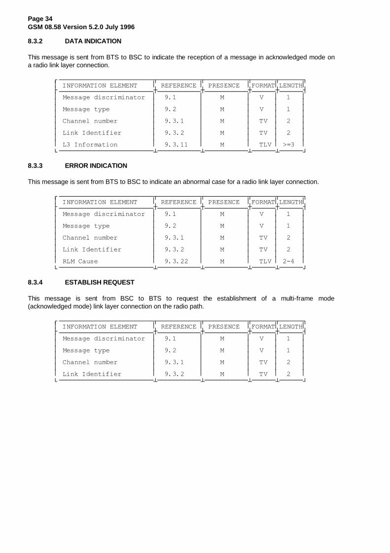
Page 34GSM 08.58 Version 5.2.0 July 1996
8.3.2 DATA INDICATION
This message is sent from BTS to BSC to indicate the reception of a message in acknowledged mode ona radio link layer connection.
¸¶¶¶¶¶¶¶¶¶¶¶¶¶¶¶¶¶¶¶¶¶¶¶¶¾¶¶¶¶¶¶¶¶¶¶¶¾¶¶¶¶¶¶¶¶¶¶¶¾¶¶¶¶¶¶¾¶¶¶¶¶¶¹·�,1)250$7,21�(/(0(17����·�5()(5(1&(�·�35(6(1&(��·)250$7·/(1*7+·¼¶¶¶¶¶¶¶¶¶¶¶¶¶¶¶¶¶¶¶¶¶¶¶¶À¶¶¶¶¶¶¶¶¶¶¶À¶¶¶¶¶¶¶¶¶¶¶À¶¶¶¶¶¶À¶¶¶¶¶¶½·�0HVVDJH�GLVFULPLQDWRU��·�����������·����0������·��9���·������··������������������������·�����������·�����������·������·������··�0HVVDJH�W\SH�����������·�����������·����0������·��9���·������··������������������������·�����������·�����������·������·������··�&KDQQHO�QXPEHU���������·�����������·����0������·��79��·������··������������������������·�����������·�����������·������·������··�/LQN�,GHQWLILHU��������·�����������·����0������·��79��·������··������������������������·�����������·�����������·������·������··�/��,QIRUPDWLRQ���������·�����������·����0������·��7/9�·�! ���·º¶¶¶¶¶¶¶¶¶¶¶¶¶¶¶¶¶¶¶¶¶¶¶¶¿¶¶¶¶¶¶¶¶¶¶¶¿¶¶¶¶¶¶¶¶¶¶¶¿¶¶¶¶¶¶¿¶¶¶¶¶¶»
8.3.3 ERROR INDICATION
This message is sent from BTS to BSC to indicate an abnormal case for a radio link layer connection.
¸¶¶¶¶¶¶¶¶¶¶¶¶¶¶¶¶¶¶¶¶¶¶¶¶¾¶¶¶¶¶¶¶¶¶¶¶¾¶¶¶¶¶¶¶¶¶¶¶¾¶¶¶¶¶¶¾¶¶¶¶¶¶¹·�,1)250$7,21�(/(0(17����·�5()(5(1&(�·�35(6(1&(��·)250$7·/(1*7+·¼¶¶¶¶¶¶¶¶¶¶¶¶¶¶¶¶¶¶¶¶¶¶¶¶À¶¶¶¶¶¶¶¶¶¶¶À¶¶¶¶¶¶¶¶¶¶¶À¶¶¶¶¶¶À¶¶¶¶¶¶½·�0HVVDJH�GLVFULPLQDWRU��·�����������·����0������·��9���·������··������������������������·�����������·�����������·������·������··�0HVVDJH�W\SH�����������·�����������·����0������·��9���·������··������������������������·�����������·�����������·������·������··�&KDQQHO�QXPEHU���������·�����������·����0������·��79��·������··������������������������·�����������·�����������·������·������··�/LQN�,GHQWLILHU��������·�����������·����0������·��79��·������··������������������������·�����������·�����������·������·������··�5/0�&DXVH��������������·�����������·����0������·��7/9�·������·º¶¶¶¶¶¶¶¶¶¶¶¶¶¶¶¶¶¶¶¶¶¶¶¶¿¶¶¶¶¶¶¶¶¶¶¶¿¶¶¶¶¶¶¶¶¶¶¶¿¶¶¶¶¶¶¿¶¶¶¶¶¶»
8.3.4 ESTABLISH REQUEST
This message is sent from BSC to BTS to request the establishment of a multi-frame mode(acknowledged mode) link layer connection on the radio path.
¸¶¶¶¶¶¶¶¶¶¶¶¶¶¶¶¶¶¶¶¶¶¶¶¶¾¶¶¶¶¶¶¶¶¶¶¶¾¶¶¶¶¶¶¶¶¶¶¶¾¶¶¶¶¶¶¾¶¶¶¶¶¶¹·�,1)250$7,21�(/(0(17����·�5()(5(1&(�·�35(6(1&(��·)250$7·/(1*7+·¼¶¶¶¶¶¶¶¶¶¶¶¶¶¶¶¶¶¶¶¶¶¶¶¶À¶¶¶¶¶¶¶¶¶¶¶À¶¶¶¶¶¶¶¶¶¶¶À¶¶¶¶¶¶À¶¶¶¶¶¶½·�0HVVDJH�GLVFULPLQDWRU��·�����������·����0������·��9���·������··������������������������·�����������·�����������·������·������··�0HVVDJH�W\SH�����������·�����������·����0������·��9���·������··������������������������·�����������·�����������·������·������··�&KDQQHO�QXPEHU���������·�����������·����0������·��79��·������··������������������������·�����������·�����������·������·������··�/LQN�,GHQWLILHU��������·�����������·����0������·��79��·������·º¶¶¶¶¶¶¶¶¶¶¶¶¶¶¶¶¶¶¶¶¶¶¶¶¿¶¶¶¶¶¶¶¶¶¶¶¿¶¶¶¶¶¶¶¶¶¶¶¿¶¶¶¶¶¶¿¶¶¶¶¶¶»

Page 35GSM 08.58 Version 5.2.0 July 1996
8.3.5 ESTABLISH CONFIRM
This message is sent from BTS to BSC to confirm the establishment of a radio link layer connection inmulti-frame (acknowledged) mode.
¸¶¶¶¶¶¶¶¶¶¶¶¶¶¶¶¶¶¶¶¶¶¶¶¶¾¶¶¶¶¶¶¶¶¶¶¶¾¶¶¶¶¶¶¶¶¶¶¶¾¶¶¶¶¶¶¾¶¶¶¶¶¶¹·�,1)250$7,21�(/(0(17����·�5()(5(1&(�·�35(6(1&(��·)250$7·/(1*7+·¼¶¶¶¶¶¶¶¶¶¶¶¶¶¶¶¶¶¶¶¶¶¶¶¶À¶¶¶¶¶¶¶¶¶¶¶À¶¶¶¶¶¶¶¶¶¶¶À¶¶¶¶¶¶À¶¶¶¶¶¶½·�0HVVDJH�GLVFULPLQDWRU��·�����������·����0������·��9���·������··������������������������·�����������·�����������·������·������··�0HVVDJH�W\SH�����������·�����������·����0������·��9���·������··������������������������·�����������·�����������·������·������··�&KDQQHO�QXPEHU���������·�����������·����0������·��79��·������··������������������������·�����������·�����������·������·������··�/LQN�,GHQWLILHU��������·�����������·����0������·��79��·������·º¶¶¶¶¶¶¶¶¶¶¶¶¶¶¶¶¶¶¶¶¶¶¶¶¿¶¶¶¶¶¶¶¶¶¶¶¿¶¶¶¶¶¶¶¶¶¶¶¿¶¶¶¶¶¶¿¶¶¶¶¶¶»
8.3.6 ESTABLISH INDICATION
This message is sent from BTS to BSC to indicate the establishment of a radio link layer connection inmulti-frame mode, initiated by an MS.
¸¶¶¶¶¶¶¶¶¶¶¶¶¶¶¶¶¶¶¶¶¶¶¶¶¾¶¶¶¶¶¶¶¶¶¶¶¾¶¶¶¶¶¶¶¶¶¶¶¾¶¶¶¶¶¶¾¶¶¶¶¶¶¹·�,1)250$7,21�(/(0(17����·�5()(5(1&(�·�35(6(1&(��·)250$7·/(1*7+·¼¶¶¶¶¶¶¶¶¶¶¶¶¶¶¶¶¶¶¶¶¶¶¶¶À¶¶¶¶¶¶¶¶¶¶¶À¶¶¶¶¶¶¶¶¶¶¶À¶¶¶¶¶¶À¶¶¶¶¶¶½·�0HVVDJH�GLVFULPLQDWRU��·�����������·����0������·��9���·������··������������������������·�����������·�����������·������·������··�0HVVDJH�W\SH�����������·�����������·����0������·��9���·������··������������������������·�����������·�����������·������·������··�&KDQQHO�QXPEHU���������·�����������·����0������·��79��·������··������������������������·�����������·�����������·������·������··�/LQN�,GHQWLILHU��������·�����������·����0������·��79��·������··������������������������·�����������·�����������·������·������··�/��,QIRUPDWLRQ���������·�����������·����2������·��7/9�·������·º¶¶¶¶¶¶¶¶¶¶¶¶¶¶¶¶¶¶¶¶¶¶¶¶¿¶¶¶¶¶¶¶¶¶¶¶¿¶¶¶¶¶¶¶¶¶¶¶¿¶¶¶¶¶¶¿¶¶¶¶¶¶»
1) The L3 Information field is present only if the SABM frame contained a non-emptyinformation field.
NOTE: The "establish mode" parameter appearing in TS GSM 04.06 is used only on the MSside.
8.3.7 RELEASE REQUEST
This message is sent from BSC to BTS to request the release of multi- frame mode of a radio link layerconnection.
¸¶¶¶¶¶¶¶¶¶¶¶¶¶¶¶¶¶¶¶¶¶¶¶¶¾¶¶¶¶¶¶¶¶¶¶¶¾¶¶¶¶¶¶¶¶¶¶¶¾¶¶¶¶¶¶¾¶¶¶¶¶¶¹·�,1)250$7,21�(/(0(17����·�5()(5(1&(�·�35(6(1&(��·)250$7·/(1*7+·¼¶¶¶¶¶¶¶¶¶¶¶¶¶¶¶¶¶¶¶¶¶¶¶¶À¶¶¶¶¶¶¶¶¶¶¶À¶¶¶¶¶¶¶¶¶¶¶À¶¶¶¶¶¶À¶¶¶¶¶¶½·�0HVVDJH�GLVFULPLQDWRU��·�����������·����0������·��9���·������··������������������������·�����������·�����������·������·������··�0HVVDJH�W\SH�����������·�����������·����0������·��9���·������··������������������������·�����������·�����������·������·������··�&KDQQHO�QXPEHU���������·�����������·����0������·��79��·������··������������������������·�����������·�����������·������·������··�/LQN�,GHQWLILHU��������·�����������·����0������·��79��·������··������������������������·�����������·�����������·������·������··�5HOHDVH�0RGH�����������·�����������·����0������·��79��·������·º¶¶¶¶¶¶¶¶¶¶¶¶¶¶¶¶¶¶¶¶¶¶¶¶¿¶¶¶¶¶¶¶¶¶¶¶¿¶¶¶¶¶¶¶¶¶¶¶¿¶¶¶¶¶¶¿¶¶¶¶¶¶»

Page 36GSM 08.58 Version 5.2.0 July 1996
8.3.8 RELEASE CONFIRM
This message is sent from BTS to BSC to confirm the release of multi- frame mode of a radio link layerconnection.
¸¶¶¶¶¶¶¶¶¶¶¶¶¶¶¶¶¶¶¶¶¶¶¶¶¾¶¶¶¶¶¶¶¶¶¶¶¾¶¶¶¶¶¶¶¶¶¶¶¾¶¶¶¶¶¶¾¶¶¶¶¶¶¹·�,1)250$7,21�(/(0(17����·�5()(5(1&(�·�35(6(1&(��·)250$7·/(1*7+·¼¶¶¶¶¶¶¶¶¶¶¶¶¶¶¶¶¶¶¶¶¶¶¶¶À¶¶¶¶¶¶¶¶¶¶¶À¶¶¶¶¶¶¶¶¶¶¶À¶¶¶¶¶¶À¶¶¶¶¶¶½·�0HVVDJH�GLVFULPLQDWRU��·�����������·����0������·��9���·������··������������������������·�����������·�����������·������·������··�0HVVDJH�W\SH�����������·�����������·����0������·��9���·������··������������������������·�����������·�����������·������·������··�&KDQQHO�QXPEHU���������·�����������·����0������·��79��·������··������������������������·�����������·�����������·������·������··�/LQN�,GHQWLILHU��������·�����������·����0������·��79��·������·º¶¶¶¶¶¶¶¶¶¶¶¶¶¶¶¶¶¶¶¶¶¶¶¶¿¶¶¶¶¶¶¶¶¶¶¶¿¶¶¶¶¶¶¶¶¶¶¶¿¶¶¶¶¶¶¿¶¶¶¶¶¶»
8.3.9 RELEASE INDICATION
This message is sent from BTS to BSC to indicate the release of a radio link layer connection (initiated byMS).
¸¶¶¶¶¶¶¶¶¶¶¶¶¶¶¶¶¶¶¶¶¶¶¶¶¾¶¶¶¶¶¶¶¶¶¶¶¾¶¶¶¶¶¶¶¶¶¶¶¾¶¶¶¶¶¶¾¶¶¶¶¶¶¹·�,1)250$7,21�(/(0(17����·�5()(5(1&(�·�35(6(1&(��·)250$7·/(1*7+·¼¶¶¶¶¶¶¶¶¶¶¶¶¶¶¶¶¶¶¶¶¶¶¶¶À¶¶¶¶¶¶¶¶¶¶¶À¶¶¶¶¶¶¶¶¶¶¶À¶¶¶¶¶¶À¶¶¶¶¶¶½·�0HVVDJH�GLVFULPLQDWRU��·�����������·����0������·��9���·������··������������������������·�����������·�����������·������·������··�0HVVDJH�W\SH�����������·�����������·����0������·��9���·������··������������������������·�����������·�����������·������·������··�&KDQQHO�QXPEHU���������·�����������·����0������·��79��·������··������������������������·�����������·�����������·������·������··�/LQN�,GHQWLILHU��������·�����������·����0������·��79��·������·º¶¶¶¶¶¶¶¶¶¶¶¶¶¶¶¶¶¶¶¶¶¶¶¶¿¶¶¶¶¶¶¶¶¶¶¶¿¶¶¶¶¶¶¶¶¶¶¶¿¶¶¶¶¶¶¿¶¶¶¶¶¶»

Page 37GSM 08.58 Version 5.2.0 July 1996
8.3.10 UNIT DATA REQUEST
This message is sent from BSC to BTS to request the sending of a message in unacknowledged mode ona radio link layer connection.
¸¶¶¶¶¶¶¶¶¶¶¶¶¶¶¶¶¶¶¶¶¶¶¶¶¾¶¶¶¶¶¶¶¶¶¶¶¾¶¶¶¶¶¶¶¶¶¶¶¾¶¶¶¶¶¶¾¶¶¶¶¶¶¹·�,1)250$7,21�(/(0(17����·�5()(5(1&(�·�35(6(1&(��·)250$7·/(1*7+·¼¶¶¶¶¶¶¶¶¶¶¶¶¶¶¶¶¶¶¶¶¶¶¶¶À¶¶¶¶¶¶¶¶¶¶¶À¶¶¶¶¶¶¶¶¶¶¶À¶¶¶¶¶¶À¶¶¶¶¶¶½·�0HVVDJH�GLVFULPLQDWRU��·�����������·����0������·��9���·������··������������������������·�����������·�����������·������·������··�0HVVDJH�W\SH�����������·�����������·����0������·��9���·������··������������������������·�����������·�����������·������·������··�&KDQQHO�QXPEHU���������·�����������·����0������·��79��·������··������������������������·�����������·�����������·������·������··�/LQN�,GHQWLILHU��������·�����������·����0������·��79��·������··������������������������·�����������·�����������·������·������··�/��,QIRUPDWLRQ���������·�����������·����0������·��7/9�·������·º¶¶¶¶¶¶¶¶¶¶¶¶¶¶¶¶¶¶¶¶¶¶¶¶¿¶¶¶¶¶¶¶¶¶¶¶¿¶¶¶¶¶¶¶¶¶¶¶¿¶¶¶¶¶¶¿¶¶¶¶¶¶»
8.3.11 UNIT DATA INDICATION
This message is sent from BTS to BSC to indicate the reception of a message in unacknowledged modeon a radio link layer connection.
¸¶¶¶¶¶¶¶¶¶¶¶¶¶¶¶¶¶¶¶¶¶¶¶¶¾¶¶¶¶¶¶¶¶¶¶¶¾¶¶¶¶¶¶¶¶¶¶¶¾¶¶¶¶¶¶¾¶¶¶¶¶¶¹·�,1)250$7,21�(/(0(17����·�5()(5(1&(�·�35(6(1&(��·)250$7·/(1*7+·¼¶¶¶¶¶¶¶¶¶¶¶¶¶¶¶¶¶¶¶¶¶¶¶¶À¶¶¶¶¶¶¶¶¶¶¶À¶¶¶¶¶¶¶¶¶¶¶À¶¶¶¶¶¶À¶¶¶¶¶¶½·�0HVVDJH�GLVFULPLQDWRU��·�����������·����0������·��9���·������··������������������������·�����������·�����������·������·������··�0HVVDJH�W\SH�����������·�����������·����0������·��9���·������··������������������������·�����������·�����������·������·������··�&KDQQHO�QXPEHU���������·�����������·����0������·��79��·������··������������������������·�����������·�����������·������·������··�/LQN�,GHQWLILHU��������·�����������·����0������·��79��·������··������������������������·�����������·�����������·������·������··�/��,QIRUPDWLRQ���������·�����������·����0������·��7/9�·������·º¶¶¶¶¶¶¶¶¶¶¶¶¶¶¶¶¶¶¶¶¶¶¶¶¿¶¶¶¶¶¶¶¶¶¶¶¿¶¶¶¶¶¶¶¶¶¶¶¿¶¶¶¶¶¶¿¶¶¶¶¶¶»

Page 38GSM 08.58 Version 5.2.0 July 1996
8.4 DEDICATED CHANNEL MANAGEMENT MESSAGES
These messages are related to Dedicated Channel Management procedures. They all have the followinggeneral format:
¸¶¶¶¶¶¶¶¶¶¶¶¶¶¶¶¶¶¶¶¶¶¶¶¶¾¶¶¶¶¶¶¶¶¶¶¶¾¶¶¶¶¶¶¶¶¶¶¶¾¶¶¶¶¶¶¾¶¶¶¶¶¶¹·�,1)250$7,21�(/(0(17����·�5()(5(1&(�·�35(6(1&(��·)250$7·/(1*7+·¼¶¶¶¶¶¶¶¶¶¶¶¶¶¶¶¶¶¶¶¶¶¶¶¶À¶¶¶¶¶¶¶¶¶¶¶À¶¶¶¶¶¶¶¶¶¶¶À¶¶¶¶¶¶À¶¶¶¶¶¶½·�0HVVDJH�GLVFULPLQDWRU��·�����������·����0������·��9���·������··������������������������·�����������·�����������·������·������··�0HVVDJH�W\SH�����������·�����������·����0������·��9���·������··������������������������·�����������·�����������·������·������··�&KDQQHO�QXPEHU���������·�����������·����0������·��79��·������·¼¶�����������������������·�����������·�����������·������·�����¶½
·��,QIRUPDWLRQ�HOHPHQWV��·�����������·�����������·������·������··��GHSHQGLQJ�RQ�PHVVDJH��·�����������·�����������·������·������··��W\SH������������������·�����������·�����������·������·������·º¶¶¶¶¶¶¶¶¶¶¶¶¶¶¶¶¶¶¶¶¶¶¶¶¿¶¶¶¶¶¶¶¶¶¶¶¿¶¶¶¶¶¶¶¶¶¶¶¿¶¶¶¶¶¶¿¶¶¶¶¶¶»
The messages concerned are the following:
Message name Reference section
CHANnel ACTIVation 8.4.1
CHANnel ACTIVation ACKnowledge 8.4.2
CHANnel ACTIVation Negative ACK 8.4.3
CONNection FAILure INDication 8.4.4
DEACTIVATE SACCH 8.4.5
ENCRyption CoMmanD 8.4.6
HANDOver DETection 8.4.7
MEASurement RESult 8.4.8
MODE MODIFY REQuest 8.4.9
MODE MODIFY ACKnowledge 8.4.10
MODE MODIFY Negative ACKnowledge 8.4.11
PHYsical CONTEXT REQuest 8.4.12
PHYsical CONTEXT CONFirm 8.4.13
RF CHANnel RELease 8.4.14
MS POWER CONTROL 8.4.15
BS POWER CONTROL 8.4.16
PREPROCecc CONFIGure 8.4.17
Pre-processed MEASurement RESult 8.4.18
RF CHANnel RELease ACKnowledge 8.4.19
SACCH INFO MODIFY 8.4.20

Page 39GSM 08.58 Version 5.2.0 July 1996
8.4.1 CHANNEL ACTIVATION
This message is sent from BSC to BTS in order to activate a radio channel. The attributes of the channelare defined in the message.
¸¶¶¶¶¶¶¶¶¶¶¶¶¶¶¶¶¶¶¶¶¶¶¶¶¾¶¶¶¶¶¶¶¶¶¶¶¾¶¶¶¶¶¶¶¶¶¶¶¾¶¶¶¶¶¶¾¶¶¶¶¶¶¹·�,1)250$7,21�(/(0(17����·�5()(5(1&(�·�35(6(1&(��·)250$7·/(1*7+·¼¶¶¶¶¶¶¶¶¶¶¶¶¶¶¶¶¶¶¶¶¶¶¶¶À¶¶¶¶¶¶¶¶¶¶¶À¶¶¶¶¶¶¶¶¶¶¶À¶¶¶¶¶¶À¶¶¶¶¶¶½·�0HVVDJH�GLVFULPLQDWRU��·�����������·����0������·��9���·������··������������������������·�����������·�����������·������·������··�0HVVDJH�W\SH�����������·�����������·����0������·��9���·������··������������������������·�����������·�����������·������·������··�&KDQQHO�QXPEHU���������·�����������·����0������·��79��·������··������������������������·�����������·�����������·������·������··�$FWLYDWLRQ�7\SH��������·�����������·����0������·��79��·������··������������������������·�����������·�����������·������·������··�&KDQQHO�0RGH�����������·�����������·����0������·��7/9�·������··������������������������·�����������·�����������·������·������··�&KDQQHO�,GHQWLILFDWLRQ�·�����������·����2������·��7/9�·������··������������������������·�����������·�����������·������·������··�(QFU\SWLRQ�LQIRUPDWLRQ�·�����������·����2������·��7/9�·�! ���··������������������������·�����������·�����������·������·������··�+DQGRYHU�5HIHUHQFH�����·�����������·����&������·��79��·������··������������������������·�����������·�����������·������·������··�%6�3RZHU���������������·�����������·����2������·��79��·������··������������������������·�����������·�����������·������·������··�06�3RZHU���������������·�����������·����2������·��79��·������··������������������������·�����������·�����������·������·������··�7LPLQJ�$GYDQFH���������·�����������·����&������·��79��·������··������������������������·�����������·�����������·������·������··�%6�3RZHU�3DUDPHWHUV����·�����������·����2������·��7/9�·�! ���··������������������������·�����������·�����������·������·������··�06�3RZHU�3DUDPHWHUV����·�����������·����2������·��7/9�·�! ���··������������������������·�����������·�����������·������·������··�3K\VLFDO�&RQWH[W�������·�����������·����2������·��7/9�·�! ���··������������������������·�����������·�����������·������·������··�6$&&+�,QIRUPDWLRQ������·�����������·����2������·��7/9�·�! ���·º¶¶¶¶¶¶¶¶¶¶¶¶¶¶¶¶¶¶¶¶¶¶¶¶¿¶¶¶¶¶¶¶¶¶¶¶¿¶¶¶¶¶¶¶¶¶¶¶¿¶¶¶¶¶¶¿¶¶¶¶¶¶»
1) The Encryption Information element is only included if ciphering is to be applied.
2) The Handover Reference element is only included if activation type is handover.
3) If BS Power, MS Power and/or Timing Advance elements are present, they are to beused to set the initial transmission power and the initial L1-header.
4) The Timing Advance element must be included if activation type is intra cell channelchange.
5) The BS and MS Power Parameters elements are included to indicate that BS and/orMS power control is to be performed by BTS. The maximum power to be used isindicated in the BS and MS Power elements respectively.
6) Optional element for additional physical channel information.
7) Included if compatibility with phase 1 is required.
8) Optional element for setting the SACCH filling information individually for this channel. Ifthis element is present, the SACCH filling information as given by this element shall beused for this channel (replacing any SACCH filling information as given by the SACCHFILLING message(s)) until the channel is released or the information is changed by aSACCH INFO MODIFY message. (If this element is not present, the SACCH filling asgiven by the SACCH FILLING message(s) shall be used.)

Page 40GSM 08.58 Version 5.2.0 July 1996
8.4.2 CHANNEL ACTIVATION ACKNOWLEDGE
This message is sent from BSC to BTS to acknowledge that the requested channel activation has beencompleted correctly.
¸¶¶¶¶¶¶¶¶¶¶¶¶¶¶¶¶¶¶¶¶¶¶¶¶¾¶¶¶¶¶¶¶¶¶¶¶¾¶¶¶¶¶¶¶¶¶¶¶¾¶¶¶¶¶¶¾¶¶¶¶¶¶¹·�,1)250$7,21�(/(0(17����·�5()(5(1&(�·�35(6(1&(��·)250$7·/(1*7+·¼¶¶¶¶¶¶¶¶¶¶¶¶¶¶¶¶¶¶¶¶¶¶¶¶À¶¶¶¶¶¶¶¶¶¶¶À¶¶¶¶¶¶¶¶¶¶¶À¶¶¶¶¶¶À¶¶¶¶¶¶½·�0HVVDJH�GLVFULPLQDWRU��·�����������·����0������·��9���·������··������������������������·�����������·�����������·������·������··�0HVVDJH�W\SH�����������·�����������·����0������·��9���·������··������������������������·�����������·�����������·������·������··�&KDQQHO�QXPEHU���������·�����������·����0������·��79��·������··������������������������·�����������·�����������·������·������··�)UDPH�QXPEHU�����������·�����������·����0������·��79��·������·º¶¶¶¶¶¶¶¶¶¶¶¶¶¶¶¶¶¶¶¶¶¶¶¶¿¶¶¶¶¶¶¶¶¶¶¶¿¶¶¶¶¶¶¶¶¶¶¶¿¶¶¶¶¶¶¿¶¶¶¶¶¶»
The Frame Number element is used by BSC to calculate the Starting Time parameter when required.
8.4.3 CHANNEL ACTIVATION NEGATIVE ACKNOWLEDGE
This message is sent from BTS to BSC to indicate that the channel activation could not be performed asrequested.
¸¶¶¶¶¶¶¶¶¶¶¶¶¶¶¶¶¶¶¶¶¶¶¶¶¾¶¶¶¶¶¶¶¶¶¶¶¾¶¶¶¶¶¶¶¶¶¶¶¾¶¶¶¶¶¶¾¶¶¶¶¶¶¹·�,1)250$7,21�(/(0(17����·�5()(5(1&(�·�35(6(1&(��·)250$7·/(1*7+·¼¶¶¶¶¶¶¶¶¶¶¶¶¶¶¶¶¶¶¶¶¶¶¶¶À¶¶¶¶¶¶¶¶¶¶¶À¶¶¶¶¶¶¶¶¶¶¶À¶¶¶¶¶¶À¶¶¶¶¶¶½·�0HVVDJH�GLVFULPLQDWRU��·�����������·����0������·��9���·������··������������������������·�����������·�����������·������·������··�0HVVDJH�W\SH�����������·�����������·����0������·��9���·������··������������������������·�����������·�����������·������·������··�&KDQQHO�QXPEHU���������·�����������·����0������·��79��·������··������������������������·�����������·�����������·������·������··�&DXVH������������������·�����������·����0������·��7/9�·�! ���·º¶¶¶¶¶¶¶¶¶¶¶¶¶¶¶¶¶¶¶¶¶¶¶¶¿¶¶¶¶¶¶¶¶¶¶¶¿¶¶¶¶¶¶¶¶¶¶¶¿¶¶¶¶¶¶¿¶¶¶¶¶¶»
If the Channel Activation message was received with an erroneous Channel number information element,the Channel Activation Negative Acknowledge message is returned with the Channel Number informationelement equal to the received (and erroneous) Channel number and the Cause value "MandatoryInformation Element Error" with Diagnostics equal to the Channel number element identifier value.
8.4.4 CONNECTION FAILURE INDICATION
This message is sent from BTS to BSC to indicate that an active connection has been broken for somereason.
¸¶¶¶¶¶¶¶¶¶¶¶¶¶¶¶¶¶¶¶¶¶¶¶¶¾¶¶¶¶¶¶¶¶¶¶¶¾¶¶¶¶¶¶¶¶¶¶¶¾¶¶¶¶¶¶¾¶¶¶¶¶¶¹·�,1)250$7,21�(/(0(17����·�5()(5(1&(�·�35(6(1&(��·)250$7·/(1*7+·¼¶¶¶¶¶¶¶¶¶¶¶¶¶¶¶¶¶¶¶¶¶¶¶¶À¶¶¶¶¶¶¶¶¶¶¶À¶¶¶¶¶¶¶¶¶¶¶À¶¶¶¶¶¶À¶¶¶¶¶¶½·�0HVVDJH�GLVFULPLQDWRU��·�����������·����0������·��9���·������··������������������������·�����������·�����������·������·������··�0HVVDJH�W\SH�����������·�����������·����0������·��9���·������··������������������������·�����������·�����������·������·������··�&KDQQHO�QXPEHU���������·�����������·����0������·��79��·������··������������������������·�����������·�����������·������·������··�&DXVH������������������·�����������·����0������·��7/9�·�! ���·º¶¶¶¶¶¶¶¶¶¶¶¶¶¶¶¶¶¶¶¶¶¶¶¶¿¶¶¶¶¶¶¶¶¶¶¶¿¶¶¶¶¶¶¶¶¶¶¶¿¶¶¶¶¶¶¿¶¶¶¶¶¶»
8.4.5 DEACTIVATE SACCH
This message is sent from BSC to BTS in order to deactivate the SACCH of an active channel.
¸¶¶¶¶¶¶¶¶¶¶¶¶¶¶¶¶¶¶¶¶¶¶¶¶¾¶¶¶¶¶¶¶¶¶¶¶¾¶¶¶¶¶¶¶¶¶¶¶¾¶¶¶¶¶¶¾¶¶¶¶¶¶¹·�,1)250$7,21�(/(0(17����·�5()(5(1&(�·�35(6(1&(��·)250$7·/(1*7+·¼¶¶¶¶¶¶¶¶¶¶¶¶¶¶¶¶¶¶¶¶¶¶¶¶À¶¶¶¶¶¶¶¶¶¶¶À¶¶¶¶¶¶¶¶¶¶¶À¶¶¶¶¶¶À¶¶¶¶¶¶½·�0HVVDJH�GLVFULPLQDWRU��·�����������·����0������·��9���·������··������������������������·�����������·�����������·������·������··�0HVVDJH�W\SH�����������·�����������·����0������·��9���·������··������������������������·�����������·�����������·������·������··�&KDQQHO�QXPEHU���������·�����������·����0������·��79��·������·º¶¶¶¶¶¶¶¶¶¶¶¶¶¶¶¶¶¶¶¶¶¶¶¶¿¶¶¶¶¶¶¶¶¶¶¶¿¶¶¶¶¶¶¶¶¶¶¶¿¶¶¶¶¶¶¿¶¶¶¶¶¶»

Page 41GSM 08.58 Version 5.2.0 July 1996
8.4.6 ENCRYPTION COMMAND
This message is sent from BSC to BTS to start ciphering mode operation.
¸¶¶¶¶¶¶¶¶¶¶¶¶¶¶¶¶¶¶¶¶¶¶¶¶¾¶¶¶¶¶¶¶¶¶¶¶¾¶¶¶¶¶¶¶¶¶¶¶¾¶¶¶¶¶¶¾¶¶¶¶¶¶¹·�,1)250$7,21�(/(0(17����·�5()(5(1&(�·�35(6(1&(��·)250$7·/(1*7+·¼¶¶¶¶¶¶¶¶¶¶¶¶¶¶¶¶¶¶¶¶¶¶¶¶À¶¶¶¶¶¶¶¶¶¶¶À¶¶¶¶¶¶¶¶¶¶¶À¶¶¶¶¶¶À¶¶¶¶¶¶½·�0HVVDJH�GLVFULPLQDWRU��·�����������·����0������·��9���·������··������������������������·�����������·�����������·������·������··�0HVVDJH�W\SH�����������·�����������·����0������·��9���·������··������������������������·�����������·�����������·������·������··�&KDQQHO�QXPEHU���������·�����������·����0������·��79��·������··������������������������·�����������·�����������·������·������··�(QFU\SWLRQ�LQIRUPDWLRQ�·�����������·����0������·��7/9�·�! ���··������������������������·�����������·�����������·������·������··�/LQN�,GHQWLILHU��������·�����������·����0������·��79��·������··������������������������·�����������·�����������·������·������··�/��,QIR��&,3+�02'�&0'��·�����������·����0������·��7/9�·������·º¶¶¶¶¶¶¶¶¶¶¶¶¶¶¶¶¶¶¶¶¶¶¶¶¿¶¶¶¶¶¶¶¶¶¶¶¿¶¶¶¶¶¶¶¶¶¶¶¿¶¶¶¶¶¶¿¶¶¶¶¶¶»
The L3 Info element contains the complete Ciphering Mode Command message as defined in TechnicalSpecification GSM 04.08.
8.4.7 HANDOVER DETECTION
This message is sent from BTS to BSC when BTS correctly receives information from an MS on thehandover activated channel.
¸¶¶¶¶¶¶¶¶¶¶¶¶¶¶¶¶¶¶¶¶¶¶¶¶¾¶¶¶¶¶¶¶¶¶¶¶¾¶¶¶¶¶¶¶¶¶¶¶¾¶¶¶¶¶¶¾¶¶¶¶¶¶¹·�,1)250$7,21�(/(0(17����·�5()(5(1&(�·�35(6(1&(��·)250$7·/(1*7+·¼¶¶¶¶¶¶¶¶¶¶¶¶¶¶¶¶¶¶¶¶¶¶¶¶À¶¶¶¶¶¶¶¶¶¶¶À¶¶¶¶¶¶¶¶¶¶¶À¶¶¶¶¶¶À¶¶¶¶¶¶½·�0HVVDJH�GLVFULPLQDWRU��·�����������·����0������·��9���·������··������������������������·�����������·�����������·������·������··�0HVVDJH�W\SH�����������·�����������·����0������·��9���·������··������������������������·�����������·�����������·������·������··�&KDQQHO�QXPEHU���������·�����������·����0������·��79��·������··������������������������·�����������·�����������·������·������··�$FFHVV�'HOD\�����������·�����������·����2������·��79��·������·º¶¶¶¶¶¶¶¶¶¶¶¶¶¶¶¶¶¶¶¶¶¶¶¶¿¶¶¶¶¶¶¶¶¶¶¶¿¶¶¶¶¶¶¶¶¶¶¶¿¶¶¶¶¶¶¿¶¶¶¶¶¶»
1) The Access Delay element is included if the sending of the handover detection message wastriggered by the reception of a handover access burst with the correct handover reference.
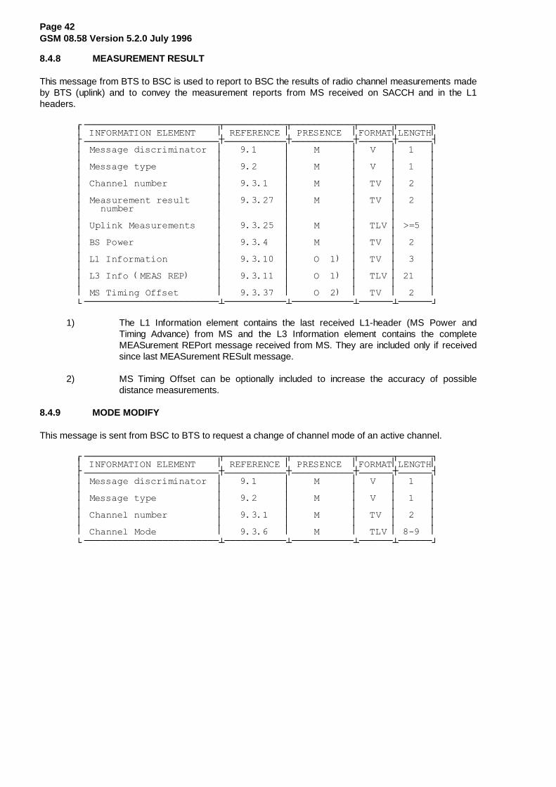
Page 42GSM 08.58 Version 5.2.0 July 1996
8.4.8 MEASUREMENT RESULT
This message from BTS to BSC is used to report to BSC the results of radio channel measurements madeby BTS (uplink) and to convey the measurement reports from MS received on SACCH and in the L1headers.
¸¶¶¶¶¶¶¶¶¶¶¶¶¶¶¶¶¶¶¶¶¶¶¶¶¾¶¶¶¶¶¶¶¶¶¶¶¾¶¶¶¶¶¶¶¶¶¶¶¾¶¶¶¶¶¶¾¶¶¶¶¶¶¹·�,1)250$7,21�(/(0(17����·�5()(5(1&(�·�35(6(1&(��·)250$7·/(1*7+·¼¶¶¶¶¶¶¶¶¶¶¶¶¶¶¶¶¶¶¶¶¶¶¶¶À¶¶¶¶¶¶¶¶¶¶¶À¶¶¶¶¶¶¶¶¶¶¶À¶¶¶¶¶¶À¶¶¶¶¶¶½·�0HVVDJH�GLVFULPLQDWRU��·�����������·����0������·��9���·������··������������������������·�����������·�����������·������·������··�0HVVDJH�W\SH�����������·�����������·����0������·��9���·������··������������������������·�����������·�����������·������·������··�&KDQQHO�QXPEHU���������·�����������·����0������·��79��·������··������������������������·�����������·�����������·������·������··�0HDVXUHPHQW�UHVXOW�����·�����������·����0������·��79��·������··���QXPEHU���������������·�����������·�����������·������·������··������������������������·�����������·�����������·������·������··�8SOLQN�0HDVXUHPHQWV����·�����������·����0������·��7/9�·�! ���··������������������������·�����������·�����������·������·������··�%6�3RZHU���������������·�����������·����0������·��79��·������··������������������������·�����������·�����������·������·������··�/��,QIRUPDWLRQ���������·�����������·����2������·��79��·������··������������������������·�����������·�����������·������·������··�/��,QIR��0($6�5(3������·�����������·����2������·��7/9�·������··������������������������·�����������·�����������·������·������··�06�7LPLQJ�2IIVHW�������·�����������·����2������·��79��·������·º¶¶¶¶¶¶¶¶¶¶¶¶¶¶¶¶¶¶¶¶¶¶¶¶¿¶¶¶¶¶¶¶¶¶¶¶¿¶¶¶¶¶¶¶¶¶¶¶¿¶¶¶¶¶¶¿¶¶¶¶¶¶»
1) The L1 Information element contains the last received L1-header (MS Power andTiming Advance) from MS and the L3 Information element contains the completeMEASurement REPort message received from MS. They are included only if receivedsince last MEASurement RESult message.
2) MS Timing Offset can be optionally included to increase the accuracy of possibledistance measurements.
8.4.9 MODE MODIFY
This message is sent from BSC to BTS to request a change of channel mode of an active channel.
¸¶¶¶¶¶¶¶¶¶¶¶¶¶¶¶¶¶¶¶¶¶¶¶¶¾¶¶¶¶¶¶¶¶¶¶¶¾¶¶¶¶¶¶¶¶¶¶¶¾¶¶¶¶¶¶¾¶¶¶¶¶¶¹·�,1)250$7,21�(/(0(17����·�5()(5(1&(�·�35(6(1&(��·)250$7·/(1*7+·¼¶¶¶¶¶¶¶¶¶¶¶¶¶¶¶¶¶¶¶¶¶¶¶¶À¶¶¶¶¶¶¶¶¶¶¶À¶¶¶¶¶¶¶¶¶¶¶À¶¶¶¶¶¶À¶¶¶¶¶¶½·�0HVVDJH�GLVFULPLQDWRU��·�����������·����0������·��9���·������··������������������������·�����������·�����������·������·������··�0HVVDJH�W\SH�����������·�����������·����0������·��9���·������··������������������������·�����������·�����������·������·������··�&KDQQHO�QXPEHU���������·�����������·����0������·��79��·������··������������������������·�����������·�����������·������·������··�&KDQQHO�0RGH�����������·�����������·����0������·��7/9�·������·º¶¶¶¶¶¶¶¶¶¶¶¶¶¶¶¶¶¶¶¶¶¶¶¶¿¶¶¶¶¶¶¶¶¶¶¶¿¶¶¶¶¶¶¶¶¶¶¶¿¶¶¶¶¶¶¿¶¶¶¶¶¶»

Page 43GSM 08.58 Version 5.2.0 July 1996
8.4.10 MODE MODIFY ACKNOWLEDGE
This message is sent from BTS to BSC to confirm the change of channel mode of an active channel.
¸¶¶¶¶¶¶¶¶¶¶¶¶¶¶¶¶¶¶¶¶¶¶¶¶¾¶¶¶¶¶¶¶¶¶¶¶¾¶¶¶¶¶¶¶¶¶¶¶¾¶¶¶¶¶¶¾¶¶¶¶¶¶¹·�,1)250$7,21�(/(0(17����·�5()(5(1&(�·�35(6(1&(��·)250$7·/(1*7+·¼¶¶¶¶¶¶¶¶¶¶¶¶¶¶¶¶¶¶¶¶¶¶¶¶À¶¶¶¶¶¶¶¶¶¶¶À¶¶¶¶¶¶¶¶¶¶¶À¶¶¶¶¶¶À¶¶¶¶¶¶½·�0HVVDJH�GLVFULPLQDWRU��·�����������·����0������·��9���·������··������������������������·�����������·�����������·������·������··�0HVVDJH�W\SH�����������·�����������·����0������·��9���·������··������������������������·�����������·�����������·������·������··�&KDQQHO�QXPEHU���������·�����������·����0������·��79��·������·º¶¶¶¶¶¶¶¶¶¶¶¶¶¶¶¶¶¶¶¶¶¶¶¶¿¶¶¶¶¶¶¶¶¶¶¶¿¶¶¶¶¶¶¶¶¶¶¶¿¶¶¶¶¶¶¿¶¶¶¶¶¶»
8.4.11 MODE MODIFY NEGATIVE ACKNOWLEDGE
This message is sent from BTS to BSC to indicate that the channel mode modification could not beperformed as requested.
¸¶¶¶¶¶¶¶¶¶¶¶¶¶¶¶¶¶¶¶¶¶¶¶¶¾¶¶¶¶¶¶¶¶¶¶¶¾¶¶¶¶¶¶¶¶¶¶¶¾¶¶¶¶¶¶¾¶¶¶¶¶¶¹·�,1)250$7,21�(/(0(17����·�5()(5(1&(�·�35(6(1&(��·)250$7·/(1*7+·¼¶¶¶¶¶¶¶¶¶¶¶¶¶¶¶¶¶¶¶¶¶¶¶¶À¶¶¶¶¶¶¶¶¶¶¶À¶¶¶¶¶¶¶¶¶¶¶À¶¶¶¶¶¶À¶¶¶¶¶¶½·�0HVVDJH�GLVFULPLQDWRU��·�����������·����0������·��9���·������··������������������������·�����������·�����������·������·������··�0HVVDJH�W\SH�����������·�����������·����0������·��9���·������··������������������������·�����������·�����������·������·������··�&KDQQHO�QXPEHU���������·�����������·����0������·��79��·������··������������������������·�����������·�����������·������·������··�&DXVH������������������·�����������·����0������·��7/9�·�! ���·º¶¶¶¶¶¶¶¶¶¶¶¶¶¶¶¶¶¶¶¶¶¶¶¶¿¶¶¶¶¶¶¶¶¶¶¶¿¶¶¶¶¶¶¶¶¶¶¶¿¶¶¶¶¶¶¿¶¶¶¶¶¶»
8.4.12 PHYSICAL CONTEXT REQUEST
This message is sent from BSC to BTS to request the "physical context" of an active channel.
¸¶¶¶¶¶¶¶¶¶¶¶¶¶¶¶¶¶¶¶¶¶¶¶¶¾¶¶¶¶¶¶¶¶¶¶¶¾¶¶¶¶¶¶¶¶¶¶¶¾¶¶¶¶¶¶¾¶¶¶¶¶¶¹·�,1)250$7,21�(/(0(17����·�5()(5(1&(�·�35(6(1&(��·)250$7·/(1*7+·¼¶¶¶¶¶¶¶¶¶¶¶¶¶¶¶¶¶¶¶¶¶¶¶¶À¶¶¶¶¶¶¶¶¶¶¶À¶¶¶¶¶¶¶¶¶¶¶À¶¶¶¶¶¶À¶¶¶¶¶¶½·�0HVVDJH�GLVFULPLQDWRU��·�����������·����0������·��9���·������··������������������������·�����������·�����������·������·������··�0HVVDJH�W\SH�����������·�����������·����0������·��9���·������··������������������������·�����������·�����������·������·������··�&KDQQHO�QXPEHU���������·�����������·����0������·��79��·������·º¶¶¶¶¶¶¶¶¶¶¶¶¶¶¶¶¶¶¶¶¶¶¶¶¿¶¶¶¶¶¶¶¶¶¶¶¿¶¶¶¶¶¶¶¶¶¶¶¿¶¶¶¶¶¶¿¶¶¶¶¶¶»

Page 44GSM 08.58 Version 5.2.0 July 1996
8.4.13 PHYSICAL CONTEXT CONFIRM
This message is sent from BTS to BSC as a response to a PHYsical CONTEXT REQuest message. Themessage contains the "physical context" information.
¸¶¶¶¶¶¶¶¶¶¶¶¶¶¶¶¶¶¶¶¶¶¶¶¶¾¶¶¶¶¶¶¶¶¶¶¶¾¶¶¶¶¶¶¶¶¶¶¶¾¶¶¶¶¶¶¾¶¶¶¶¶¶¹·�,1)250$7,21�(/(0(17����·�5()(5(1&(�·�35(6(1&(��·)250$7·/(1*7+·¼¶¶¶¶¶¶¶¶¶¶¶¶¶¶¶¶¶¶¶¶¶¶¶¶À¶¶¶¶¶¶¶¶¶¶¶À¶¶¶¶¶¶¶¶¶¶¶À¶¶¶¶¶¶À¶¶¶¶¶¶½·�0HVVDJH�GLVFULPLQDWRU��·�����������·����0������·��9���·������··������������������������·�����������·�����������·������·������··�0HVVDJH�W\SH�����������·�����������·����0������·��9���·������··������������������������·�����������·�����������·������·������··�&KDQQHO�QXPEHU���������·�����������·����0������·��79��·������··������������������������·�����������·�����������·������·������··�%6�3RZHU���������������·�����������·����0������·��79��·������··������������������������·�����������·�����������·������·������··�06�3RZHU���������������·�����������·����0������·��79��·������··������������������������·�����������·�����������·������·������··�7LPLQJ�$GYDQFH���������·�����������·����0������·��79��·������··������������������������·�����������·�����������·������·������··�3K\VLFDO�&RQWH[W�������·�����������·����2������·��7/9�·�! ���·º¶¶¶¶¶¶¶¶¶¶¶¶¶¶¶¶¶¶¶¶¶¶¶¶¿¶¶¶¶¶¶¶¶¶¶¶¿¶¶¶¶¶¶¶¶¶¶¶¿¶¶¶¶¶¶¿¶¶¶¶¶¶»
1) Optional element for additional physical channel information.
8.4.14 RF CHANNEL RELEASE
This message is sent from BSC to BTS to inform that a radio channel is no longer needed.
¸¶¶¶¶¶¶¶¶¶¶¶¶¶¶¶¶¶¶¶¶¶¶¶¶¾¶¶¶¶¶¶¶¶¶¶¶¾¶¶¶¶¶¶¶¶¶¶¶¾¶¶¶¶¶¶¾¶¶¶¶¶¶¹·�,1)250$7,21�(/(0(17����·�5()(5(1&(�·�35(6(1&(��·)250$7·/(1*7+·¼¶¶¶¶¶¶¶¶¶¶¶¶¶¶¶¶¶¶¶¶¶¶¶¶À¶¶¶¶¶¶¶¶¶¶¶À¶¶¶¶¶¶¶¶¶¶¶À¶¶¶¶¶¶À¶¶¶¶¶¶½·�0HVVDJH�GLVFULPLQDWRU��·�����������·����0������·��9���·������··������������������������·�����������·�����������·������·������··�0HVVDJH�W\SH�����������·�����������·����0������·��9���·������··������������������������·�����������·�����������·������·������··�&KDQQHO�QXPEHU���������·�����������·����0������·��79��·������·º¶¶¶¶¶¶¶¶¶¶¶¶¶¶¶¶¶¶¶¶¶¶¶¶¿¶¶¶¶¶¶¶¶¶¶¶¿¶¶¶¶¶¶¶¶¶¶¶¿¶¶¶¶¶¶¿¶¶¶¶¶¶»
8.4.15 MS POWER CONTROL
This message is sent from BSC to BTS to change the MS power level or the parameters used by TRX tocontrol the MS power.
¸¶¶¶¶¶¶¶¶¶¶¶¶¶¶¶¶¶¶¶¶¶¶¶¶¾¶¶¶¶¶¶¶¶¶¶¶¾¶¶¶¶¶¶¶¶¶¶¶¾¶¶¶¶¶¶¾¶¶¶¶¶¶¹·�,1)250$7,21�(/(0(17����·�5()(5(1&(�·�35(6(1&(��·)250$7·/(1*7+·¼¶¶¶¶¶¶¶¶¶¶¶¶¶¶¶¶¶¶¶¶¶¶¶¶À¶¶¶¶¶¶¶¶¶¶¶À¶¶¶¶¶¶¶¶¶¶¶À¶¶¶¶¶¶À¶¶¶¶¶¶½·�0HVVDJH�GLVFULPLQDWRU��·�����������·����0������·��9���·������··������������������������·�����������·�����������·������·������··�0HVVDJH�W\SH�����������·�����������·����0������·��9���·������··������������������������·�����������·�����������·������·������··�&KDQQHO�QXPEHU���������·�����������·����0������·��79��·������··������������������������·�����������·�����������·������·������··�06�3RZHU���������������·�����������·����0������·��79��·������··������������������������·�����������·�����������·������·������··�06�3RZHU�3DUDPHWHUV����·�����������·����2������·��7/9�·�! ���·º¶¶¶¶¶¶¶¶¶¶¶¶¶¶¶¶¶¶¶¶¶¶¶¶¿¶¶¶¶¶¶¶¶¶¶¶¿¶¶¶¶¶¶¶¶¶¶¶¿¶¶¶¶¶¶¿¶¶¶¶¶¶»
1) If the MS Power Parameters element is present it indicates that the MS power controlis to be performed by TRX. The MS Power element then indicates the maximum MSpower to be used.

Page 45GSM 08.58 Version 5.2.0 July 1996
8.4.16 BS POWER CONTROL
This message is sent from BSC to BTS to change the TRX transmission power level or the parametersused by TRX to control its transmission power.
¸¶¶¶¶¶¶¶¶¶¶¶¶¶¶¶¶¶¶¶¶¶¶¶¶¾¶¶¶¶¶¶¶¶¶¶¶¾¶¶¶¶¶¶¶¶¶¶¶¾¶¶¶¶¶¶¾¶¶¶¶¶¶¹·�,1)250$7,21�(/(0(17����·�5()(5(1&(�·�35(6(1&(��·)250$7·/(1*7+·¼¶¶¶¶¶¶¶¶¶¶¶¶¶¶¶¶¶¶¶¶¶¶¶¶À¶¶¶¶¶¶¶¶¶¶¶À¶¶¶¶¶¶¶¶¶¶¶À¶¶¶¶¶¶À¶¶¶¶¶¶½·�0HVVDJH�GLVFULPLQDWRU��·�����������·����0������·��9���·������··������������������������·�����������·�����������·������·������··�0HVVDJH�W\SH�����������·�����������·����0������·��9���·������··������������������������·�����������·�����������·������·������··�&KDQQHO�QXPEHU���������·�����������·����0������·��79��·������··������������������������·�����������·�����������·������·������··�%6�3RZHU���������������·�����������·����0������·��79��·������··������������������������·�����������·�����������·������·������··�%6�3RZHU�3DUDPHWHUV����·�����������·����2������·��7/9�·�! ���·º¶¶¶¶¶¶¶¶¶¶¶¶¶¶¶¶¶¶¶¶¶¶¶¶¿¶¶¶¶¶¶¶¶¶¶¶¿¶¶¶¶¶¶¶¶¶¶¶¿¶¶¶¶¶¶¿¶¶¶¶¶¶»
1) If the BS Power Parameters element is present it indicates that the TRX transmissionpower control is to be performed by TRX. The BS Power element then indicates themaximum transmission power to be used.
8.4.17 PRE-PROCESS CONFIGURE
This message is sent from BSC to BTS to modify the pre-processing parameters used by BTS.
¸¶¶¶¶¶¶¶¶¶¶¶¶¶¶¶¶¶¶¶¶¶¶¶¶¾¶¶¶¶¶¶¶¶¶¶¶¾¶¶¶¶¶¶¶¶¶¶¶¾¶¶¶¶¶¶¾¶¶¶¶¶¶¹·�,1)250$7,21�(/(0(17����·�5()(5(1&(�·�35(6(1&(��·)250$7·/(1*7+·¼¶¶¶¶¶¶¶¶¶¶¶¶¶¶¶¶¶¶¶¶¶¶¶¶À¶¶¶¶¶¶¶¶¶¶¶À¶¶¶¶¶¶¶¶¶¶¶À¶¶¶¶¶¶À¶¶¶¶¶¶½·�0HVVDJH�GLVFULPLQDWRU��·�����������·����0������·��9���·������··������������������������·�����������·�����������·������·������··�0HVVDJH�W\SH�����������·�����������·����0������·��9���·������··������������������������·�����������·�����������·������·������··�&KDQQHO�QXPEHU���������·�����������·����0������·��79��·������··������������������������·�����������·�����������·������·������··�3UHSURF��3DUDPHWHUV����·�����������·����0������·��7/9�·�! ���·º¶¶¶¶¶¶¶¶¶¶¶¶¶¶¶¶¶¶¶¶¶¶¶¶¿¶¶¶¶¶¶¶¶¶¶¶¿¶¶¶¶¶¶¶¶¶¶¶¿¶¶¶¶¶¶¿¶¶¶¶¶¶»
8.4.18 PRE-PROCESSED MEASUREMENT RESULT
This message is used by BTS to report the results of radio parameter pre-processing.
¸¶¶¶¶¶¶¶¶¶¶¶¶¶¶¶¶¶¶¶¶¶¶¶¶¾¶¶¶¶¶¶¶¶¶¶¶¾¶¶¶¶¶¶¶¶¶¶¶¾¶¶¶¶¶¶¾¶¶¶¶¶¶¹·�,1)250$7,21�(/(0(17����·�5()(5(1&(�·�35(6(1&(��·)250$7·/(1*7+·¼¶¶¶¶¶¶¶¶¶¶¶¶¶¶¶¶¶¶¶¶¶¶¶¶À¶¶¶¶¶¶¶¶¶¶¶À¶¶¶¶¶¶¶¶¶¶¶À¶¶¶¶¶¶À¶¶¶¶¶¶½·�0HVVDJH�GLVFULPLQDWRU��·�����������·����0������·��9���·������··������������������������·�����������·�����������·������·������··�0HVVDJH�W\SH�����������·�����������·����0������·��9���·������··������������������������·�����������·�����������·������·������··�&KDQQHO�QXPEHU���������·�����������·����0������·��79��·������··������������������������·�����������·�����������·������·������··�3UHSURF��0HDVXUHPHQWV��·�����������·����0������·��7/9�·�! ���·º¶¶¶¶¶¶¶¶¶¶¶¶¶¶¶¶¶¶¶¶¶¶¶¶¿¶¶¶¶¶¶¶¶¶¶¶¿¶¶¶¶¶¶¶¶¶¶¶¿¶¶¶¶¶¶¿¶¶¶¶¶¶»
8.4.19 RF CHANNEL RELEASE ACKNOWLEDGE
This message is sent from BTS to BSC as an acknowledge to a RF CHANnel RELease message.
¸¶¶¶¶¶¶¶¶¶¶¶¶¶¶¶¶¶¶¶¶¶¶¶¶¾¶¶¶¶¶¶¶¶¶¶¶¾¶¶¶¶¶¶¶¶¶¶¶¾¶¶¶¶¶¶¾¶¶¶¶¶¶¹·�,1)250$7,21�(/(0(17����·�5()(5(1&(�·�35(6(1&(��·)250$7·/(1*7+·¼¶¶¶¶¶¶¶¶¶¶¶¶¶¶¶¶¶¶¶¶¶¶¶¶À¶¶¶¶¶¶¶¶¶¶¶À¶¶¶¶¶¶¶¶¶¶¶À¶¶¶¶¶¶À¶¶¶¶¶¶½·�0HVVDJH�GLVFULPLQDWRU��·�����������·����0������·��9���·������··������������������������·�����������·�����������·������·������··�0HVVDJH�W\SH�����������·�����������·����0������·��9���·������··������������������������·�����������·�����������·������·������··�&KDQQHO�QXPEHU���������·�����������·����0������·��79��·������·º¶¶¶¶¶¶¶¶¶¶¶¶¶¶¶¶¶¶¶¶¶¶¶¶¿¶¶¶¶¶¶¶¶¶¶¶¿¶¶¶¶¶¶¶¶¶¶¶¿¶¶¶¶¶¶¿¶¶¶¶¶¶»

Page 46GSM 08.58 Version 5.2.0 July 1996
8.4.20 SACCH INFO MODIFY
This message is sent from BSC to BTS to modify the SACCH filling information (System Information) senton an individual SACCH channel. This new SACCH filling information shall be sent on the indicated channeluntil the channel is released or the information is changed by another SACCH INFO MODIFY message.
¸¶¶¶¶¶¶¶¶¶¶¶¶¶¶¶¶¶¶¶¶¶¶¶¶¾¶¶¶¶¶¶¶¶¶¶¶¾¶¶¶¶¶¶¶¶¶¶¶¾¶¶¶¶¶¶¾¶¶¶¶¶¶¹·�,1)250$7,21�(/(0(17����·�5()(5(1&(�·�35(6(1&(��·)250$7·/(1*7+·¼¶¶¶¶¶¶¶¶¶¶¶¶¶¶¶¶¶¶¶¶¶¶¶¶À¶¶¶¶¶¶¶¶¶¶¶À¶¶¶¶¶¶¶¶¶¶¶À¶¶¶¶¶¶À¶¶¶¶¶¶½·�0HVVDJH�GLVFULPLQDWRU��·�����������·����0������·��9���·������··������������������������·�����������·�����������·������·������··�0HVVDJH�W\SH�����������·�����������·����0������·��9���·������··������������������������·�����������·�����������·������·������··�&KDQQHO�QXPEHU���������·�����������·����0������·��79��·������··������������������������·�����������·�����������·������·������··�6\VWHP�,QIR�7\SH�������·�����������·����0������·��79��·������··������������������������·�����������·�����������·������·������··�/��,QIR��6<6�,1)2������·�����������·����2������·��7/9�·������··������������������������·�����������·�����������·������·������··�6WDUWLQ�7LPH�����������·�����������·����2������·��79��·������·º¶¶¶¶¶¶¶¶¶¶¶¶¶¶¶¶¶¶¶¶¶¶¶¶¿¶¶¶¶¶¶¶¶¶¶¶¿¶¶¶¶¶¶¶¶¶¶¶¿¶¶¶¶¶¶¿¶¶¶¶¶¶»
1) If the L3 Info information element is not included, this indicates that transmission of theindicated SYSTEM INFORMATION message shall be stopped, i.e. this SYSTEMINFORMATION message shall no longer be sent on this channel.
2) The Starting Time element is optionally used to indicate when transmission of the newinformation is to start and when transmission is to stop.
The System Info Type element indicates the type of SYSTEM INFORMATION message which follows inthe L3 Info field.
The L3 Information element contains the relevant SYSTEM INFORMATION message as defined inTechnical Specification GSM 04.08.
8.5 COMMON CHANNEL MANAGEMENT MESSAGES
These messages are related to Common Channel Management procedures. They all have the followinggeneral format:
¸¶¶¶¶¶¶¶¶¶¶¶¶¶¶¶¶¶¶¶¶¶¶¶¶¾¶¶¶¶¶¶¶¶¶¶¶¾¶¶¶¶¶¶¶¶¶¶¶¾¶¶¶¶¶¶¾¶¶¶¶¶¶¹·�,1)250$7,21�(/(0(17����·�5()(5(1&(�·�35(6(1&(��·)250$7·/(1*7+·¼¶¶¶¶¶¶¶¶¶¶¶¶¶¶¶¶¶¶¶¶¶¶¶¶À¶¶¶¶¶¶¶¶¶¶¶À¶¶¶¶¶¶¶¶¶¶¶À¶¶¶¶¶¶À¶¶¶¶¶¶½·�0HVVDJH�GLVFULPLQDWRU��·�����������·����0������·��9���·������··������������������������·�����������·�����������·������·������··�0HVVDJH�W\SH�����������·�����������·����0������·��9���·������··������������������������·�����������·�����������·������·������··�&KDQQHO�QXPEHU���������·�����������·����0������·��79��·������·¼¶�����������������������·�����������·�����������·������·�����¶½����������������������������������������������������������������·��,QIRUPDWLRQ�HOHPHQWV��·�����������·�����������·������·������··��GHSHQGLQJ�RQ�PHVVDJH��·�����������·�����������·������·������··��W\SH������������������·�����������·�����������·������·������·º¶¶¶¶¶¶¶¶¶¶¶¶¶¶¶¶¶¶¶¶¶¶¶¶¿¶¶¶¶¶¶¶¶¶¶¶¿¶¶¶¶¶¶¶¶¶¶¶¿¶¶¶¶¶¶¿¶¶¶¶¶¶»
The messages concerned are the following:
Message name Reference section
BCCH INFOrmation 8.5.1CCCH LOAD INDication 8.5.2CHANnel ReQuireD 8.5.3DELETE INDication 8.5.4PAGING CoMmanD 8.5.5IMMEDIATE ASSIGN COMMAND 8.5.6SMS BroadCast REQuest 8.5.7SMS Broadcast Command 8.5.8CBCH LOAD INDICATION 8.5.9

Page 47GSM 08.58 Version 5.2.0 July 1996
8.5.1 BCCH INFORMATION
This message is sent from BSC to BTS to indicate new information to be broadcast on BCCH.
¸¶¶¶¶¶¶¶¶¶¶¶¶¶¶¶¶¶¶¶¶¶¶¶¶¾¶¶¶¶¶¶¶¶¶¶¶¾¶¶¶¶¶¶¶¶¶¶¶¾¶¶¶¶¶¶¾¶¶¶¶¶¶¹·�,1)250$7,21�(/(0(17����·�5()(5(1&(�·�35(6(1&(��·)250$7·/(1*7+·¼¶¶¶¶¶¶¶¶¶¶¶¶¶¶¶¶¶¶¶¶¶¶¶¶À¶¶¶¶¶¶¶¶¶¶¶À¶¶¶¶¶¶¶¶¶¶¶À¶¶¶¶¶¶À¶¶¶¶¶¶½·�0HVVDJH�GLVFULPLQDWRU��·�����������·����0������·��9���·������··������������������������·�����������·�����������·������·������··�0HVVDJH�W\SH�����������·�����������·����0������·��9���·������··������������������������·�����������·�����������·������·������··�&KDQQHO�QXPEHU���������·�����������·����0������·��79��·������··������������������������·�����������·�����������·������·������··�6\VWHP�,QIR�7\SH�������·�����������·����0������·��79��·������··������������������������·�����������·�����������·������·������··�)XOO�%&&+�,QIR���������·�����������·����2������·��7/9�·������··����6<6�,1)2������������·�����������·�����������·������·������··������������������������·�����������·�����������·������·������··�6WDUWLQJ�7LPH����������·�����������·����2������·��79��·������·º¶¶¶¶¶¶¶¶¶¶¶¶¶¶¶¶¶¶¶¶¶¶¶¶¿¶¶¶¶¶¶¶¶¶¶¶¿¶¶¶¶¶¶¶¶¶¶¶¿¶¶¶¶¶¶¿¶¶¶¶¶¶»
1) If the Full BCCH information element is not included this indicates that transmission ofthe indicated SYSTEM INFORMATION message shall be stopped.
2) The Starting Time element is optionally used to indicate when transmission of the newinformation is to start or when transmission is to stop.
The System Info Type element indicates the type of SYSTEM INFORMATION message which follows inthe Full BCCH Information element.
The Full BCCH Information element contains the relevant SYSTEM INFORMATION message as defined inTechnical Specification GSM 04.08.
8.5.2 CCCH LOAD INDICATION
This message is sent from BTS to BSC to report the current load on the indicated CCCH timeslot (randomaccess, RACH, and paging, PCH).
¸¶¶¶¶¶¶¶¶¶¶¶¶¶¶¶¶¶¶¶¶¶¶¶¶¾¶¶¶¶¶¶¶¶¶¶¶¾¶¶¶¶¶¶¶¶¶¶¶¾¶¶¶¶¶¶¾¶¶¶¶¶¶¹·�,1)250$7,21�(/(0(17����·�5()(5(1&(�·�35(6(1&(��·)250$7·/(1*7+·¼¶¶¶¶¶¶¶¶¶¶¶¶¶¶¶¶¶¶¶¶¶¶¶¶À¶¶¶¶¶¶¶¶¶¶¶À¶¶¶¶¶¶¶¶¶¶¶À¶¶¶¶¶¶À¶¶¶¶¶¶½·�0HVVDJH�GLVFULPLQDWRU��·�����������·����0������·��9���·������··������������������������·�����������·�����������·������·������··�0HVVDJH�W\SH�����������·�����������·����0������·��9���·������··������������������������·�����������·�����������·������·������··�&KDQQHO�QXPEHU��QRWH���·�����������·����0������·��79��·������··������������������������·�����������·�����������·������·������··�5$&+�/RDG��������������·�����������·����&������·��7/9�·�! ���··������������������������·�����������·�����������·������·������··�3DJLQJ�/RDG������������·�����������·����&������·��79��·������·º¶¶¶¶¶¶¶¶¶¶¶¶¶¶¶¶¶¶¶¶¶¶¶¶¿¶¶¶¶¶¶¶¶¶¶¶¿¶¶¶¶¶¶¶¶¶¶¶¿¶¶¶¶¶¶¿¶¶¶¶¶¶»
NOTE: The BTS may set the "Channel Number" information element in this message to eitherthe "uplink CCCH" or the "downlink CCCH" on that timeslot number.
1) The RACH load information element is included only if the Channel number informationindicates "uplink CCCH".
2) The Paging load information element is included only if the Channel number informationindicates "downlink CCCH".

Page 48GSM 08.58 Version 5.2.0 July 1996
8.5.3 CHANNEL REQUIRED
This message is sent from BTS to BSC to indicate the reception of a CHANnel REQuest message (specialaccess burst message) from an MS.
¸¶¶¶¶¶¶¶¶¶¶¶¶¶¶¶¶¶¶¶¶¶¶¶¶¾¶¶¶¶¶¶¶¶¶¶¶¾¶¶¶¶¶¶¶¶¶¶¶¾¶¶¶¶¶¶¾¶¶¶¶¶¶¹·�,1)250$7,21�(/(0(17����·�5()(5(1&(�·�35(6(1&(��·)250$7·/(1*7+·¼¶¶¶¶¶¶¶¶¶¶¶¶¶¶¶¶¶¶¶¶¶¶¶¶À¶¶¶¶¶¶¶¶¶¶¶À¶¶¶¶¶¶¶¶¶¶¶À¶¶¶¶¶¶À¶¶¶¶¶¶½·�0HVVDJH�GLVFULPLQDWRU��·�����������·����0������·��9���·������··������������������������·�����������·�����������·������·������··�0HVVDJH�W\SH�����������·�����������·����0������·��9���·������··������������������������·�����������·�����������·������·������··�&KDQQHO�QXPEHU���������·�����������·����0������·��79��·������··������������������������·�����������·�����������·������·������··�5HTXHVW�5HIHUHQFH������·�����������·����0������·��79��·������··������������������������·�����������·�����������·������·������··�$FFHVV�'HOD\�����������·�����������·����0������·��79��·������··������������������������·�����������·�����������·������·������··�3K\VLFDO�&RQWH[W�������·�����������·����2������·��7/9�·�! ���·º¶¶¶¶¶¶¶¶¶¶¶¶¶¶¶¶¶¶¶¶¶¶¶¶¿¶¶¶¶¶¶¶¶¶¶¶¿¶¶¶¶¶¶¶¶¶¶¶¿¶¶¶¶¶¶¿¶¶¶¶¶¶»
1) Optional element for additional physical channel information.
The Request Reference element contains the random access reference value sent by MS in the CHANnelREQuest message and some low order bits of the absolute frame number for the reception of the accessburst.
8.5.4 DELETE INDICATION
This message is sent from BTS to BSC to indicate the deletion of an access grant message (IMMediateASSIGN) due to overload of downlink CCCH.
¸¶¶¶¶¶¶¶¶¶¶¶¶¶¶¶¶¶¶¶¶¶¶¶¶¾¶¶¶¶¶¶¶¶¶¶¶¾¶¶¶¶¶¶¶¶¶¶¶¾¶¶¶¶¶¶¾¶¶¶¶¶¶¹·�,1)250$7,21�(/(0(17����·�5()(5(1&(�·�35(6(1&(��·)250$7·/(1*7+·¼¶¶¶¶¶¶¶¶¶¶¶¶¶¶¶¶¶¶¶¶¶¶¶¶À¶¶¶¶¶¶¶¶¶¶¶À¶¶¶¶¶¶¶¶¶¶¶À¶¶¶¶¶¶À¶¶¶¶¶¶½·�0HVVDJH�GLVFULPLQDWRU��·�����������·����0������·��9���·������··������������������������·�����������·�����������·������·������··�0HVVDJH�W\SH�����������·�����������·����0������·��9���·������··������������������������·�����������·�����������·������·������··�&KDQQHO�QXPEHU���������·�����������·����0������·��79��·������··������������������������·�����������·�����������·������·������··�)XOO�,PP��$VVLJQ�,QIR��·�����������·����0������·��7/9�·������·º¶¶¶¶¶¶¶¶¶¶¶¶¶¶¶¶¶¶¶¶¶¶¶¶¿¶¶¶¶¶¶¶¶¶¶¶¿¶¶¶¶¶¶¶¶¶¶¶¿¶¶¶¶¶¶¿¶¶¶¶¶¶»
8.5.5 PAGING COMMAND
This message is sent from BSC to BTS to request the paging of an MS.
¸¶¶¶¶¶¶¶¶¶¶¶¶¶¶¶¶¶¶¶¶¶¶¶¶¾¶¶¶¶¶¶¶¶¶¶¶¾¶¶¶¶¶¶¶¶¶¶¶¾¶¶¶¶¶¶¾¶¶¶¶¶¶¹·�,1)250$7,21�(/(0(17����·�5()(5(1&(�·�35(6(1&(��·)250$7·/(1*7+·¼¶¶¶¶¶¶¶¶¶¶¶¶¶¶¶¶¶¶¶¶¶¶¶¶À¶¶¶¶¶¶¶¶¶¶¶À¶¶¶¶¶¶¶¶¶¶¶À¶¶¶¶¶¶À¶¶¶¶¶¶½·�0HVVDJH�GLVFULPLQDWRU��·�����������·����0������·��9���·������··������������������������·�����������·�����������·������·������··�0HVVDJH�W\SH�����������·�����������·����0������·��9���·������··������������������������·�����������·�����������·������·������··�&KDQQHO�QXPEHU���������·�����������·����0������·��79��·������··������������������������·�����������·�����������·������·������··�3DJLQJ�*URXS�����������·�����������·����0������·��79��·������··������������������������·�����������·�����������·������·������··�06�,GHQWLW\������������·�����������·����0������·��7/9�·������··������������������������·�����������·�����������·������·������··�&KDQQHO�1HHGHG���������·�����������·����2������·��79��·������·º¶¶¶¶¶¶¶¶¶¶¶¶¶¶¶¶¶¶¶¶¶¶¶¶¿¶¶¶¶¶¶¶¶¶¶¶¿¶¶¶¶¶¶¶¶¶¶¶¿¶¶¶¶¶¶¿¶¶¶¶¶¶»
1) If the Channel Needed element is not present, the default value is assumed to be 00(any channel).
The Paging Group element is used by BTS to calculate the correct DRX paging block to be used for thetransmission of the PAGing REQuest message as defined in Technical Specification GSM 05.02.

Page 49GSM 08.58 Version 5.2.0 July 1996
8.5.6 IMMEDIATE ASSIGN COMMAND
This message is sent from BSC to BTS to request the transmission of an immediate assignment message.
¸¶¶¶¶¶¶¶¶¶¶¶¶¶¶¶¶¶¶¶¶¶¶¶¶¾¶¶¶¶¶¶¶¶¶¶¶¾¶¶¶¶¶¶¶¶¶¶¶¾¶¶¶¶¶¶¾¶¶¶¶¶¶¹·�,1)250$7,21�(/(0(17����·�5()(5(1&(�·�35(6(1&(��·)250$7·/(1*7+·¼¶¶¶¶¶¶¶¶¶¶¶¶¶¶¶¶¶¶¶¶¶¶¶¶À¶¶¶¶¶¶¶¶¶¶¶À¶¶¶¶¶¶¶¶¶¶¶À¶¶¶¶¶¶À¶¶¶¶¶¶½·�0HVVDJH�GLVFULPLQDWRU��·�����������·����0������·��9���·������··������������������������·�����������·�����������·������·������··�0HVVDJH�W\SH�����������·�����������·����0������·��9���·������··������������������������·�����������·�����������·������·������··�&KDQQHO�QXPEHU���������·�����������·����0������·��79��·������··������������������������·�����������·�����������·������·������··�)XOO�,PP��$VVLJQ�,QIR��·�����������·����0������·��7/9�·������·º¶¶¶¶¶¶¶¶¶¶¶¶¶¶¶¶¶¶¶¶¶¶¶¶¿¶¶¶¶¶¶¶¶¶¶¶¿¶¶¶¶¶¶¶¶¶¶¶¿¶¶¶¶¶¶¿¶¶¶¶¶¶»
The Full Imm. Assign Info element contains the relevant immediate assignment message as defined inTechnical Specification GSM 04.08 (IMMEDIATE ASSIGNMENT or IMMEDIATE ASSIGNMENTEXTENDED or IMMEDIATE ASSIGNMENT REJECT) with the "Page Mode" element set to the value "nochange".
8.5.7 SMS BROADCAST REQUEST
This message is sent from BSC to BTS to request the sending of a Short Message Service Cell Broadcastmessage.
¸¶¶¶¶¶¶¶¶¶¶¶¶¶¶¶¶¶¶¶¶¶¶¶¶¾¶¶¶¶¶¶¶¶¶¶¶¾¶¶¶¶¶¶¶¶¶¶¶¾¶¶¶¶¶¶¾¶¶¶¶¶¶¹·�,1)250$7,21�(/(0(17����·�5()(5(1&(�·�35(6(1&(��·)250$7·/(1*7+·¼¶¶¶¶¶¶¶¶¶¶¶¶¶¶¶¶¶¶¶¶¶¶¶¶À¶¶¶¶¶¶¶¶¶¶¶À¶¶¶¶¶¶¶¶¶¶¶À¶¶¶¶¶¶À¶¶¶¶¶¶½·�0HVVDJH�GLVFULPLQDWRU��·�����������·����0������·��9���·������··������������������������·�����������·�����������·������·������··�0HVVDJH�W\SH�����������·�����������·����0������·��9���·������··������������������������·�����������·�����������·������·������··�&KDQQHO�QXPEHU���������·�����������·����0������·��79��·������··������������������������·�����������·�����������·������·������··�606&%�,QIRUPDWLRQ������·�����������·����0������·��79��·������··������������������������·�����������·�����������·������·������··�606&%�&KDQQHO�,QGLFDWRU·�����������·����2������·��79��·������·º¶¶¶¶¶¶¶¶¶¶¶¶¶¶¶¶¶¶¶¶¶¶¶¶¿¶¶¶¶¶¶¶¶¶¶¶¿¶¶¶¶¶¶¶¶¶¶¶¿¶¶¶¶¶¶¿¶¶¶¶¶¶»
The SMSCB Information element contains the complete information to be broadcast on the CBCH asdefined in TS GSM 04.12 (including the Layer 2 header to be used on the radio path).
1) The SMSCB Channel Indicator IE indicates the CBCH which shall be used for broadcasting the data.If this information element is not present the basic CBCH [see GSM 05.02] shall be used.
8.5.8 SMS BROADCAST COMMAND
This message is sent from BSC to BTS to command Short Message Service Cell Broadcast.
¸¶¶¶¶¶¶¶¶¶¶¶¶¶¶¶¶¶¶¶¶¶¶¶¶¾¶¶¶¶¶¶¶¶¶¶¶¾¶¶¶¶¶¶¶¶¶¶¶¾¶¶¶¶¶¶¾¶¶¶¶¶¶¹·�,1)250$7,21�(/(0(17����·�5()(5(1&(�·�35(6(1&(��·)250$7·/(1*7+·¼¶¶¶¶¶¶¶¶¶¶¶¶¶¶¶¶¶¶¶¶¶¶¶¶À¶¶¶¶¶¶¶¶¶¶¶À¶¶¶¶¶¶¶¶¶¶¶À¶¶¶¶¶¶À¶¶¶¶¶¶½·�0HVVDJH�GLVFULPLQDWRU��·�����������·����0������·��9���·������··������������������������·�����������·�����������·������·������··�0HVVDJH�W\SH�����������·�����������·����0������·��9���·������··������������������������·�����������·�����������·������·������··�&KDQQHO�QXPEHU���������·�����������·����0������·��79��·������··������������������������·�����������·�����������·������·������··�&%�&RPPDQG�W\SH��������·�����������·����0������·��79��·������··������������������������·�����������·�����������·������·������··�606&%�PHVVDJH����������·�����������·����0������·��7/9�·������··������������������������·�����������·�����������·������·������··�606&%�&KDQQHO�,QGLFDWRU·�����������·����2������·��79��·������·º¶¶¶¶¶¶¶¶¶¶¶¶¶¶¶¶¶¶¶¶¶¶¶¶¿¶¶¶¶¶¶¶¶¶¶¶¿¶¶¶¶¶¶¶¶¶¶¶¿¶¶¶¶¶¶¿¶¶¶¶¶¶»
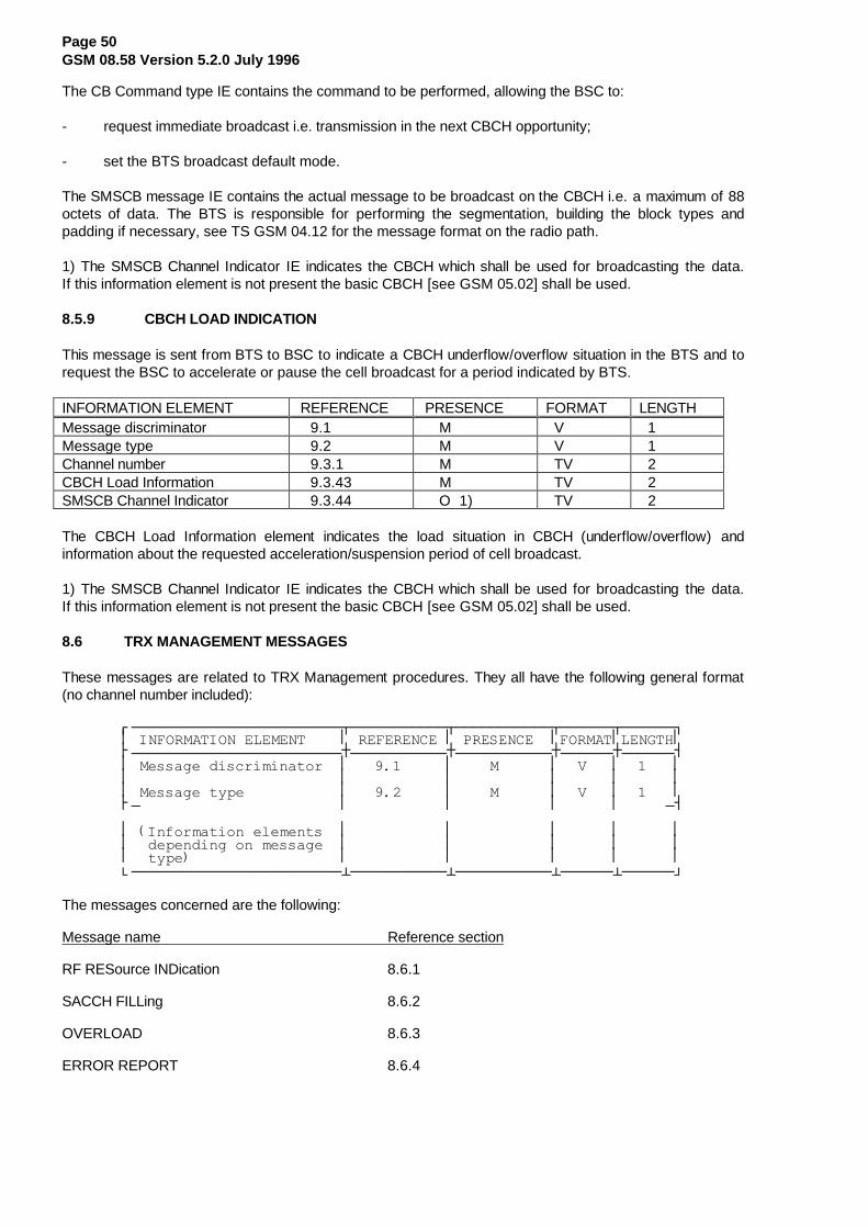
Page 50GSM 08.58 Version 5.2.0 July 1996
The CB Command type IE contains the command to be performed, allowing the BSC to:
- request immediate broadcast i.e. transmission in the next CBCH opportunity;
- set the BTS broadcast default mode.
The SMSCB message IE contains the actual message to be broadcast on the CBCH i.e. a maximum of 88octets of data. The BTS is responsible for performing the segmentation, building the block types andpadding if necessary, see TS GSM 04.12 for the message format on the radio path.
1) The SMSCB Channel Indicator IE indicates the CBCH which shall be used for broadcasting the data.If this information element is not present the basic CBCH [see GSM 05.02] shall be used.
8.5.9 CBCH LOAD INDICATION
This message is sent from BTS to BSC to indicate a CBCH underflow/overflow situation in the BTS and torequest the BSC to accelerate or pause the cell broadcast for a period indicated by BTS.
INFORMATION ELEMENT REFERENCE PRESENCE FORMAT LENGTHMessage discriminator 9.1 M V 1Message type 9.2 M V 1Channel number 9.3.1 M TV 2CBCH Load Information 9.3.43 M TV 2SMSCB Channel Indicator 9.3.44 O 1) TV 2
The CBCH Load Information element indicates the load situation in CBCH (underflow/overflow) andinformation about the requested acceleration/suspension period of cell broadcast.
1) The SMSCB Channel Indicator IE indicates the CBCH which shall be used for broadcasting the data.If this information element is not present the basic CBCH [see GSM 05.02] shall be used.
8.6 TRX MANAGEMENT MESSAGES
These messages are related to TRX Management procedures. They all have the following general format(no channel number included):
¸¶¶¶¶¶¶¶¶¶¶¶¶¶¶¶¶¶¶¶¶¶¶¶¶¾¶¶¶¶¶¶¶¶¶¶¶¾¶¶¶¶¶¶¶¶¶¶¶¾¶¶¶¶¶¶¾¶¶¶¶¶¶¹·�,1)250$7,21�(/(0(17����·�5()(5(1&(�·�35(6(1&(��·)250$7·/(1*7+·¼¶¶¶¶¶¶¶¶¶¶¶¶¶¶¶¶¶¶¶¶¶¶¶¶À¶¶¶¶¶¶¶¶¶¶¶À¶¶¶¶¶¶¶¶¶¶¶À¶¶¶¶¶¶À¶¶¶¶¶¶½·�0HVVDJH�GLVFULPLQDWRU��·�����������·����0������·��9���·������··������������������������·�����������·�����������·������·������··�0HVVDJH�W\SH�����������·�����������·����0������·��9���·������·¼¶�����������������������·�����������·�����������·������·�����¶½
·��,QIRUPDWLRQ�HOHPHQWV��·�����������·�����������·������·������··��GHSHQGLQJ�RQ�PHVVDJH��·�����������·�����������·������·������··��W\SH������������������·�����������·�����������·������·������·º¶¶¶¶¶¶¶¶¶¶¶¶¶¶¶¶¶¶¶¶¶¶¶¶¿¶¶¶¶¶¶¶¶¶¶¶¿¶¶¶¶¶¶¶¶¶¶¶¿¶¶¶¶¶¶¿¶¶¶¶¶¶»
The messages concerned are the following:
Message name Reference section
RF RESource INDication 8.6.1
SACCH FILLing 8.6.2
OVERLOAD 8.6.3
ERROR REPORT 8.6.4

Page 51GSM 08.58 Version 5.2.0 July 1996
8.6.1 RF RESOURCE INDICATION
This message is sent from BTS to BSC to indicate the interference level on idle channels of a TRX.
¸¶¶¶¶¶¶¶¶¶¶¶¶¶¶¶¶¶¶¶¶¶¶¶¶¾¶¶¶¶¶¶¶¶¶¶¶¾¶¶¶¶¶¶¶¶¶¶¶¾¶¶¶¶¶¶¾¶¶¶¶¶¶¹·�,1)250$7,21�(/(0(17����·�5()(5(1&(�·�35(6(1&(��·)250$7·/(1*7+·¼¶¶¶¶¶¶¶¶¶¶¶¶¶¶¶¶¶¶¶¶¶¶¶¶À¶¶¶¶¶¶¶¶¶¶¶À¶¶¶¶¶¶¶¶¶¶¶À¶¶¶¶¶¶À¶¶¶¶¶¶½·�0HVVDJH�GLVFULPLQDWRU��·�����������·����0������·��9���·������··������������������������·�����������·�����������·������·������··�0HVVDJH�W\SH�����������·�����������·����0������·��9���·������··������������������������·�����������·�����������·������·������··�5HVRXUFH�,QIRUPDWLRQ���·�����������·����0������·��7/9�·�! ���·º¶¶¶¶¶¶¶¶¶¶¶¶¶¶¶¶¶¶¶¶¶¶¶¶¿¶¶¶¶¶¶¶¶¶¶¶¿¶¶¶¶¶¶¶¶¶¶¶¿¶¶¶¶¶¶¿¶¶¶¶¶¶»
8.6.2 SACCH FILLING
This message is sent from BSC to BTS to indicate the new broadcast information to be used as fillinginformation on downlink SACCH.
¸¶¶¶¶¶¶¶¶¶¶¶¶¶¶¶¶¶¶¶¶¶¶¶¶¾¶¶¶¶¶¶¶¶¶¶¶¾¶¶¶¶¶¶¶¶¶¶¶¾¶¶¶¶¶¶¾¶¶¶¶¶¶¹·�,1)250$7,21�(/(0(17����·�5()(5(1&(�·�35(6(1&(��·)250$7·/(1*7+·¼¶¶¶¶¶¶¶¶¶¶¶¶¶¶¶¶¶¶¶¶¶¶¶¶À¶¶¶¶¶¶¶¶¶¶¶À¶¶¶¶¶¶¶¶¶¶¶À¶¶¶¶¶¶À¶¶¶¶¶¶½·�0HVVDJH�GLVFULPLQDWRU��·�����������·����0������·��9���·������··������������������������·�����������·�����������·������·������··�0HVVDJH�W\SH�����������·�����������·����0������·��9���·������··������������������������·�����������·�����������·������·������··�6\VWHP�,QIR�7\SH�������·�����������·����0������·��79��·������··������������������������·�����������·�����������·������·������··�/��,QIR��6<6�,1)2������·�����������·����2������·��7/9�·������··������������������������·�����������·�����������·������·������··�6WDUWLQJ�7LPH����������·�����������·����2������·��79��·������·º¶¶¶¶¶¶¶¶¶¶¶¶¶¶¶¶¶¶¶¶¶¶¶¶¿¶¶¶¶¶¶¶¶¶¶¶¿¶¶¶¶¶¶¶¶¶¶¶¿¶¶¶¶¶¶¿¶¶¶¶¶¶»
1) If the L3 Info information element is not included this indicates that transmission of theindicated SYSTEM INFORMATION message shall be stopped.
2) The Starting Time element is optionally used to indicate when transmission of the newinformation is to start and when transmission is to stop.
The System Info Type element indicates the type of SYSTEM INFORMATION message which follows inthe L3 Info field.
The L3 Information element contains the relevant SYSTEM INFORMATION message as defined inTechnical Specification GSM 04.08.
8.6.3 OVERLOAD
This message is sent from BTS to BSC to indicate an overload situation. Possible cause values include:
- CCCH overload,- ACCH overload,- processor overload.
¸¶¶¶¶¶¶¶¶¶¶¶¶¶¶¶¶¶¶¶¶¶¶¶¶¾¶¶¶¶¶¶¶¶¶¶¶¾¶¶¶¶¶¶¶¶¶¶¶¾¶¶¶¶¶¶¾¶¶¶¶¶¶¹·�,1)250$7,21�(/(0(17����·�5()(5(1&(�·�35(6(1&(��·)250$7·/(1*7+·¼¶¶¶¶¶¶¶¶¶¶¶¶¶¶¶¶¶¶¶¶¶¶¶¶À¶¶¶¶¶¶¶¶¶¶¶À¶¶¶¶¶¶¶¶¶¶¶À¶¶¶¶¶¶À¶¶¶¶¶¶½·�0HVVDJH�GLVFULPLQDWRU��·�����������·����0������·��9���·������··������������������������·�����������·�����������·������·������··�0HVVDJH�W\SH�����������·�����������·����0������·��9���·������··������������������������·�����������·�����������·������·������··�&DXVH������������������·�����������·����0������·��7/9�·�! ���·º¶¶¶¶¶¶¶¶¶¶¶¶¶¶¶¶¶¶¶¶¶¶¶¶¿¶¶¶¶¶¶¶¶¶¶¶¿¶¶¶¶¶¶¶¶¶¶¶¿¶¶¶¶¶¶¿¶¶¶¶¶¶»

Page 52GSM 08.58 Version 5.2.0 July 1996
8.6.4 ERROR REPORT
This message is sent from BTS to BSC to report a detected error which cannot be reported in any othermessage.
¸¶¶¶¶¶¶¶¶¶¶¶¶¶¶¶¶¶¶¶¶¶¶¶¶¾¶¶¶¶¶¶¶¶¶¶¶¾¶¶¶¶¶¶¶¶¶¶¶¾¶¶¶¶¶¶¾¶¶¶¶¶¶¹·�,1)250$7,21�(/(0(17����·�5()(5(1&(�·�35(6(1&(��·)250$7·/(1*7+·¼¶¶¶¶¶¶¶¶¶¶¶¶¶¶¶¶¶¶¶¶¶¶¶¶À¶¶¶¶¶¶¶¶¶¶¶À¶¶¶¶¶¶¶¶¶¶¶À¶¶¶¶¶¶À¶¶¶¶¶¶½·�0HVVDJH�GLVFULPLQDWRU��·�����������·����0������·��9���·������··������������������������·�����������·�����������·������·������··�0HVVDJH�W\SH�����������·�����������·����0������·��9���·������··������������������������·�����������·�����������·������·������··�&DXVH������������������·�����������·����0������·��7/9�·�! ���··������������������������·�����������·�����������·������·������··�0HVVDJH�,GHQWLILHU�����·�����������·����2������·��79��·������··������������������������·�����������·�����������·������·������··�&KDQQHO�1XPEHU���������·�����������·����2������·��79��·������··������������������������·�����������·�����������·������·������··�/LQN�LGHQWLILHU��������·�����������·����2������·��79��·������··������������������������·�����������·�����������·������·������··�(UURQHRXV�0HVVDJH������·�����������·����2������·��7/9�·�! ���·º¶¶¶¶¶¶¶¶¶¶¶¶¶¶¶¶¶¶¶¶¶¶¶¶¿¶¶¶¶¶¶¶¶¶¶¶¿¶¶¶¶¶¶¶¶¶¶¶¿¶¶¶¶¶¶¿¶¶¶¶¶¶»
1) Used to indicate which type of message was considered erroneous.
2) Used to indicate for which radio channel the error is reported.
3) Used to indicate for which radio L2 link the error is reported.
4) This element may be used to carry the complete erroneous message as it wasreceived from the BSC.

Page 53GSM 08.58 Version 5.2.0 July 1996
9 Information element codings
This section contains the codings of the signalling elements used. The following conventions are assumedfor the sequence of transmission of bits and bytes :
�����������������������������������������������¸¶¶¶¶¶¶¶¶¶¶¶¶¶¶¶¹������(DFK�ELW�SRVLWLRQ�LV�QXPEHUHG�DV���WR����·���������������·�����������������������������������������������º¶¶¶¶¶¶¶¶¶¶¶¶¶¶¶»
- The least significant bit is bit 1 and is transmitted first, followed by bits 2, 3, 4 etc.
- In an element, octets are identified by number. Octet 1 is transmitted first, then octet 2 etc.
- When a field extends over more than one octet, the order of bit values progressively decreases asthe octet number increases. The least significant bit of the field is represented by the lowestnumbered bit of the highest numbered octet of the field.
- For variable length elements, a length indicator is included. This indicates the number of octetsfollowing in the element.
- All spare or reserved bits are set to 0.
9.1 Message discriminator
A 1 octet field is used in all messages to discriminate between Transparent and Non-Transparentmessages and also between Radio Link Layer Management, Dedicated Channel Management, CommonChannel Management and TRX Management messages.
���������������������������������������¸¶¶¶¶¶¶¶¶¶¶¶¶¶¶¶¶¶¶¶¶¶¶¶¶¶¶¶¾¶¶¶¹����·*���*���*���*���*���*���*��·�7�·����º¶¶¶¶¶¶¶¶¶¶¶¶¶¶¶¶¶¶¶¶¶¶¶¶¶¶¶¿¶¶¶»
The T-bit is set to 1 to indicate that the message is to be/was considered transparent by BTS. All othermessages shall have the T-bit set to 0.
The G-bits are used to group the messages as follows:
G7 G6 G5 G4 G3 G2 G1 Message Group
0 0 0 0 0 0 0 reserved 0 0 0 0 0 0 1 Radio Link Layer Management messages 0 0 0 0 1 0 0 Dedicated Channel Management messages 0 0 0 0 1 1 0 Common Channel Management messages 0 0 0 1 0 0 0 TRX Management messages
All other values are reserved for future use.

Page 54GSM 08.58 Version 5.2.0 July 1996
9.2 MESSAGE TYPE
The Message Type uniquely identifies the function of the message being sent. It is a single octet andcoded in the following way:
��������������������������¸¶¶¶¾¶¶¶¶¶¶¶¶¶¶¶¶¶¶¶¶¶¶¶¶¶¶¹·(0����0HVVDJH�W\SH��������·º¶¶¶¿¶¶¶¶¶¶¶¶¶¶¶¶¶¶¶¶¶¶¶¶¶¶»
Bit 8 is the extension bit and is reserved for future use. The following message types are used (all othervalues are reserved):
8 7 6 5 4 3 2 1 Message Reference0 0 0 0 - - - - Radio Link Layer Management messages: 0 0 0 1 - DATA REQuest 8.3.1 0 0 1 0 - DATA INDication 8.3.2 0 0 1 1 - ERROR INDication 8.3.3 0 1 0 0 - ESTablish REQuest 8.3.4 0 1 0 1 - ESTablish CONFirm 8.3.5 0 1 1 0 - ESTablish INDication 8.3.6 0 1 1 1 - RELease REQuest 8.3.7 1 0 0 0 - RELease CONFirm 8.3.8 1 0 0 1 - RELease INDication 8.3.9 1 0 1 0 - UNIT DATA REQuest 8.3.10 1 0 1 1 - UNIT DATA INDication 8.3.11
0 0 0 1 - - - - Common Channel Management/TRX Management messages: 0 0 0 1 - BCCH INFOrmation 8.5.1 0 0 1 0 - CCCH LOAD INDication 8.5.2 0 0 1 1 - CHANnel ReQuireD 8.5.3 0 1 0 0 - DELETE INDication 8.5.4 0 1 0 1 - PAGING CoMmanD 8.5.5 0 1 1 0 - IMMEDIATE ASSIGN COMMAND 8.5.6 0 1 1 1 - SMS BroadCast REQuest 8.5.7 1 0 0 1 - RF RESource INDication 8.6.1 1 0 1 0 - SACCH FILLing 8.6.2 1 0 1 1 - OVERLOAD 8.6.3 1 1 0 0 - ERROR REPORT 8.6.4 1 1 0 1 - SMS BroadCast CoMmanD 8.5.8 1 1 1 0 - CBCH LOAD INDication 8.5.9
0 0 1 - - - - - Dedicated Channel Management messages: 0 0 0 0 1 - CHANnel ACTIVation 8.4.1 0 0 0 1 0 - CHANnel ACTIVation ACKnowledge 8.4.2 0 0 0 1 1 - CHANnel ACTIVation Negative ACK 8.4.3 0 0 1 0 0 - CONNection FAILure 8.4.4 0 0 1 0 1 - DEACTIVATE SACCH 8.4.5 0 0 1 1 0 - ENCRyption CoMmanD 8.4.6 0 0 1 1 1 - HANDOver DETection 8.4.7 0 1 0 0 0 - MEASurement RESult 8.4.8 0 1 0 0 1 - MODE MODIFY REQuest 8.4.9 0 1 0 1 0 - MODE MODIFY ACKnowledge 8.4.10 0 1 0 1 1 - MODE MODIFY Negative ACKnowledge 8.4.11 0 1 1 0 0 - PHYsical CONTEXT REQuest 8.4.12 0 1 1 0 1 - PHYsical CONTEXT CONFirm 8.4.13 0 1 1 1 0 - RF CHANnel RELease 8.4.14 0 1 1 1 1 - MS POWER CONTROL 8.4.15 1 0 0 0 0 - BS POWER CONTROL 8.4.16 1 0 0 0 1 - Pre-process CONFIGure 8.4.17 1 0 0 1 0 - Pre-processed MEASurement RESult 8.4.18 1 0 0 1 1 - RF CHANnel RELease ACKnowledge8.4.19 1 0 1 0 0 - SACCH INFO MODIFY 8.4.20

Page 55GSM 08.58 Version 5.2.0 July 1996
9.3 Other information elements
The information elements used and the coding of their Element Identifier fields are:
ElementIdentifier bits 8 7 6 5 4 3 2 1 Element name Reference
0 0 0 0 0 0 0 1 Channel Number 9.3.1 0 0 0 0 0 0 1 0 Link Identifier 9.3.2 0 0 0 0 0 0 1 1 Activation Type 9.3.3 0 0 0 0 0 1 0 0 BS Power 9.3.4 0 0 0 0 0 1 0 1 Channel Identification 9.3.5
0 0 0 0 0 1 1 0 Channel Mode 9.3.6 0 0 0 0 0 1 1 1 Encryption Information 9.3.7 0 0 0 0 1 0 0 0 Frame Number 9.3.8 0 0 0 0 1 0 0 1 Handover Reference 9.3.9 0 0 0 0 1 0 1 0 L1 Information 9.3.10
0 0 0 0 1 0 1 1 L3 Information 9.3.11 0 0 0 0 1 1 0 0 MS Identity 9.3.12 0 0 0 0 1 1 0 1 MS Power 9.3.13 0 0 0 0 1 1 1 0 Paging Group 9.3.14 0 0 0 0 1 1 1 1 Paging Load 9.3.15
0 0 0 1 0 0 0 0 Physical Context 9.3.16 0 0 0 1 0 0 0 1 Access Delay 9.3.17 0 0 0 1 0 0 1 0 RACH Load 9.3.18 0 0 0 1 0 0 1 1 Request Reference 9.3.19 0 0 0 1 0 1 0 0 Release Mode 9.3.20
0 0 0 1 0 1 0 1 Resource Information 9.3.21 0 0 0 1 0 1 1 0 RLM Cause 9.3.22 0 0 0 1 0 1 1 1 Starting Time 9.3.23 0 0 0 1 1 0 0 0 Timing Advance 9.3.24 0 0 0 1 1 0 0 1 Uplink Measurements 9.3.25
0 0 0 1 1 0 1 0 Cause 9.3.26 0 0 0 1 1 0 1 1 Measurement result number 9.3.27 0 0 0 1 1 1 0 0 Message Identifier 9.3.28 0 0 0 1 1 1 0 1 reserved 0 0 0 1 1 1 1 0 System Info Type 9.3.30
0 0 0 1 1 1 1 1 MS Power Parameters 9.3.31 0 0 1 0 0 0 0 0 BS Power Parameters 9.3.32 0 0 1 0 0 0 0 1 Pre-processing Parameters 9.3.33 0 0 1 0 0 0 1 0 Pre-processed Measurements 9.3.34 0 0 1 0 0 0 1 1 reserved
0 0 1 0 0 1 0 0 SMSCB Information 9.3.36 0 0 1 0 0 1 0 1 MS Timing Offset 9.3.37 0 0 1 0 0 1 1 0 Erroneous Message 9.3.38 0 0 1 0 0 1 1 1 Full BCCH Information 9.3.39 0 0 1 0 1 0 0 0 Channel Needed 9.3.40 0 0 1 0 1 0 0 1 CB Command type 9.3.41 0 0 1 0 1 0 1 0 SMSCB message 9.3.420 0 1 0 1 0 1 1 Full Immediate Assign Info 9.3.35
0 0 1 0 1 1 0 0 SACCH Information 9.3.29 0 0 1 0 1 1 0 1 CBCH Load Information 9.3.43 0 0 1 0 1 1 1 0 SMSCB Channel Indicator 9.3.44
0 0 1 0 1 1 1 1 to 1 1 1 0 1 1 1 1 Reserved for future use
1 1 1 1 0 0 0 0 to 1 1 1 1 1 1 1 1 Not used

Page 56GSM 08.58 Version 5.2.0 July 1996
9.3.1 Channel Number
In the direction BSC to BTS the Channel Number parameter is used to indicate on which physicalchannel/subchannel the message is to be sent. In the direction BTS to BSC the Channel Number indicateson which physical channel/subchannel the message was received. It is coded in two octets as follows:
��������������������������������������������¸¶¶¶¶¶¶¶¶¶¶¶¶¶¶¶¶¶¶¶¶¶¶¶¶¶¶¶¶¶¶¶¶¶¶¶¶¶¶¶¶¶¶¶¹
��·������������(OHPHQW�LGHQWLILHU�������������·��¼¶¶¶¶¶¶¶¶¶¶¶¶¶¶¶¶¶¶¶¶¶¶¶¶¶¶¶¾¶¶¶¶¶¶¶¶¶¶¶¶¶¶¶½
��·&�����&�����&�����&�����&��·�����71��������·��º¶¶¶¶¶¶¶¶¶¶¶¶¶¶¶¶¶¶¶¶¶¶¶¶¶¶¶¿¶¶¶¶¶¶¶¶¶¶¶¶¶¶¶»
The C-bits describe the channel as follows:
C5 C4 C3 C2 C1 0 0 0 0 1 Bm + ACCH's 0 0 0 1 T Lm + ACCH's 0 0 1 T T SDCCH/4 + ACCH 0 1 T T T SDCCH/8 + ACCH 1 0 0 0 0 BCCH 1 0 0 0 1 Uplink CCCH (RACH) 1 0 0 1 0 Downlink CCCH (PCH + AGCH)
The T-bits indicate, coded in binary, the sub-channel number as specified in Technical SpecificationGSM 05.02.
TN is time slot number, binary represented as in TS GSM 05.02.
9.3.2 Link Identifier
This element identifies the signalling channel and SAPI of the radio data link.
��������������������������������������������¸¶¶¶¶¶¶¶¶¶¶¶¶¶¶¶¶¶¶¶¶¶¶¶¶¶¶¶¶¶¶¶¶¶¶¶¶¶¶¶¶¶¶¶¹
��·������������(OHPHQW�LGHQWLILHU�������������·��¼¶¶¶¶¶¶¶¶¶¾¶¶¶¶¶¾¶¶¶¶¶¶¶¶¶¶¶¾¶¶¶¶¶¶¶¶¶¶¶¶¶¶¶½
��·&�����&��·�1$��·�UHVHUYHG��·�����6$3,������·��º¶¶¶¶¶¶¶¶¶¿¶¶¶¶¶¿¶¶¶¶¶¶¶¶¶¶¶¿¶¶¶¶¶¶¶¶¶¶¶¶¶¶¶»
The NA bit (bit 6 in octet 2) is set to 1 to indicate that the Link Identifier is not applicable for this message.In all other cases it is set to 0.
The C-bits indicate the channel type as follows:
C2 C1
0 0 main signalling channel (FACCH or SDCCH)
0 1 SACCH
All other values are reserved for future use.
The SAPI field contains the SAPI value as defined in Technical Specification GSM 04.05.

Page 57GSM 08.58 Version 5.2.0 July 1996
9.3.3 Activation Type
This element is used to indicate the type of activation requested in the CHANnel ACTIVation message. It iscoded in two octets as follows:
��������������������������������������������¸¶¶¶¶¶¶¶¶¶¶¶¶¶¶¶¶¶¶¶¶¶¶¶¶¶¶¶¶¶¶¶¶¶¶¶¶¶¶¶¶¶¶¶¹
��·������������(OHPHQW�LGHQWLILHU�������������·��¼¶¶¶¶¶¶¶¶¶¶¶¶¶¶¶¶¶¶¶¶¶¶¶¶¶¶¶¾¶¶¶¶¶¶¶¶¶¶¶¶¶¶¶½
��·��5HVHUYHG�IRU�IXWXUH�XVH��·�$�����$�����$�·��º¶¶¶¶¶¶¶¶¶¶¶¶¶¶¶¶¶¶¶¶¶¶¶¶¶¶¶¿¶¶¶¶¶¶¶¶¶¶¶¶¶¶¶»
The A-bits indicate the type of activation as follows:
A3 A2 A1
0 0 - Activation related to intra-cell channel change 0 - related to immediate assignment procedure 1 - related to normal assignment procedure
0 1 - Activation related to inter-cell channel change (handover) 0 - related to asynchronous handover procedure 1 - related to synchronous handover procedure 1 0 0 Activation related to additional assignment procedure
All other values reserved for future use.
9.3.4 BS Power
This information element indicates the TRX transmission power level on a particular channel.
��������������������������������������������¸¶¶¶¶¶¶¶¶¶¶¶¶¶¶¶¶¶¶¶¶¶¶¶¶¶¶¶¶¶¶¶¶¶¶¶¶¶¶¶¶¶¶¶¹
��·������������(OHPHQW�LGHQWLILHU�������������·��¼¶¶¶¶¶¶¶¶¶¶¶¶¶¶¶¾¶¶¶¶¶¶¶¶¶¶¶¶¶¶¶¶¶¶¶¶¶¶¶¶¶¶¶½
��·���5HVHUYHG����·��������3RZHU�/HYHO��������·��º¶¶¶¶¶¶¶¶¶¶¶¶¶¶¶¿¶¶¶¶¶¶¶¶¶¶¶¶¶¶¶¶¶¶¶¶¶¶¶¶¶¶¶»
The Power Level field (octet 2) indicates the number of 2 dB steps by which the power shall be reducedfrom its nominal value, Pn, set by the network operator to adjust the coverage. Thus the Power Levelvalues correspond to the following powers (relative to Pn):
Value Power level
0 0 0 0 0 Pn
0 0 0 0 1 Pn - 2 dB
0 0 0 1 0 Pn - 4 dB
.
.
0 1 1 1 0 Pn - 28 dB
0 1 1 1 1 Pn - 30 dB
All other values are reserved for future use.
See also Technical Specifications GSM 05.05, section 4.1.2 and GSM 05.08, section 4.5.
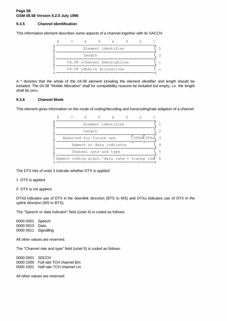
Page 58GSM 08.58 Version 5.2.0 July 1996
9.3.5 Channel Identification
This information element describes some aspects of a channel together with its SACCH.
��������������������������������������������¸¶¶¶¶¶¶¶¶¶¶¶¶¶¶¶¶¶¶¶¶¶¶¶¶¶¶¶¶¶¶¶¶¶¶¶¶¶¶¶¶¶¶¶¹
��·������������(OHPHQW�LGHQWLILHU�������������·��¼¶¶¶¶¶¶¶¶¶¶¶¶¶¶¶¶¶¶¶¶¶¶¶¶¶¶¶¶¶¶¶¶¶¶¶¶¶¶¶¶¶¶¶½
��·������������/HQJWK�������������������������·��¼¶¶¶¶¶¶¶¶¶¶¶¶¶¶¶¶¶¶¶¶¶¶¶¶¶¶¶¶¶¶¶¶¶¶¶¶¶¶¶¶¶¶¶½
��·������������&KDQQHO�'HVFULSWLRQ������������·� ¼¶¶¶¶¶¶¶¶¶¶¶¶¶¶¶¶¶¶¶¶¶¶¶¶¶¶¶¶¶¶¶¶¶¶¶¶¶¶¶¶¶¶¶½
��·������������0RELOH�$OORFDWLRQ��������������·� º¶¶¶¶¶¶¶¶¶¶¶¶¶¶¶¶¶¶¶¶¶¶¶¶¶¶¶¶¶¶¶¶¶¶¶¶¶¶¶¶¶¶¶»
A * denotes that the whole of the 04.08 element including the element identifier and length should beincluded. The 04.08 "Mobile Allocation" shall for compatibility reasons be included but empty, i.e. the lengthshall be zero.
9.3.6 Channel Mode
This element gives information on the mode of coding/decoding and transcoding/rate adaption of a channel.
��������������������������������������������¸¶¶¶¶¶¶¶¶¶¶¶¶¶¶¶¶¶¶¶¶¶¶¶¶¶¶¶¶¶¶¶¶¶¶¶¶¶¶¶¶¶¶¶¹
��·������������(OHPHQW�LGHQWLILHU�������������·��¼¶¶¶¶¶¶¶¶¶¶¶¶¶¶¶¶¶¶¶¶¶¶¶¶¶¶¶¶¶¶¶¶¶¶¶¶¶¶¶¶¶¶¶½
��·������������/HQJWK�������������������������·��¼¶¶¶¶¶¶¶¶¶¶¶¶¶¶¶¶¶¶¶¶¶¶¶¶¶¶¶¶¶¶¶¶¶¾¶¶¶¶¾¶¶¶¶½
��·���5HVHUYHG�IRU�IXWXUH�XVH�������·'7;G·'7;X·��¼¶¶¶¶¶¶¶¶¶¶¶¶¶¶¶¶¶¶¶¶¶¶¶¶¶¶¶¶¶¶¶¶¶¿¶¶¶¶¿¶¶¶¶½
��·�������6SHHFK�RU�GDWD�LQGLFDWRU������������·��¼¶¶¶¶¶¶¶¶¶¶¶¶¶¶¶¶¶¶¶¶¶¶¶¶¶¶¶¶¶¶¶¶¶¶¶¶¶¶¶¶¶¶¶½
��·�������&KDQQHO�UDWH�DQG�W\SH���������������·��¼¶¶¶¶¶¶¶¶¶¶¶¶¶¶¶¶¶¶¶¶¶¶¶¶¶¶¶¶¶¶¶¶¶¶¶¶¶¶¶¶¶¶¶½
��·6SHHFK�FRGLQJ�DOJRU��GDWD�UDWH���WUDQVS�LQG·��º¶¶¶¶¶¶¶¶¶¶¶¶¶¶¶¶¶¶¶¶¶¶¶¶¶¶¶¶¶¶¶¶¶¶¶¶¶¶¶¶¶¶¶»
The DTX bits of octet 3 indicate whether DTX is applied:
1 DTX is applied
0 DTX is not applied.
DTXd indicates use of DTX in the downlink direction (BTS to MS) and DTXu indicates use of DTX in theuplink direction (MS to BTS).
The "Speech or data indicator" field (octet 4) is coded as follows:
0000 0001 Speech0000 0010 Data0000 0011 Signalling
All other values are reserved.
The "Channel rate and type" field (octet 5) is coded as follows:
0000 0001 SDCCH0000 1000 Full rate TCH channel Bm0000 1001 Half rate TCH channel Lm
All other values are reserved.

Page 59GSM 08.58 Version 5.2.0 July 1996
The "speech coding algorithm/data rate + transparency indicator" field (octet 6) is coded as follows:
If octet 4 indicates speech, then octet 6 is coded as follows:
0000 0001 GSM speech coding algorithm version 10001 0001 GSM speech coding algorithm version 20010 0001 GSM speech coding algorithm version 3
All other values are reserved.
If octet 4 indicates signalling then octet 6 is coded as follows:
0000 0000 No resources required
All other values are reserved.
If octet 4 indicates data, then octet 6 is coded as follows:
���������������������������������������������¸¶¶¶¶¾¶¶¶¶¶¾¶¶¶¶¶¶¶¶¶¶¶¶¶¶¶¶¶¶¶¶¶¶¶¶¶¶¶¶¶¶¶¶¶¶¹
��������·H[W�·7�17�·�������������5DWH�����������������·�RFWHW��º¶¶¶¶¿¶¶¶¶¶¿¶¶¶¶¶¶¶¶¶¶¶¶¶¶¶¶¶¶¶¶¶¶¶¶¶¶¶¶¶¶¶¶¶¶»
Bit 8: Reserved for extension
Bit 7: 0 Transparent service
1 Non-transparent service.
For the non-transparent service, bits 6-1 indicate the radio interface data rate:
65 4321
01 0000 12 kbit/s01 0001 6 kbit/s
all other values are reserved.
For the transparent service, bits 6-1 indicate the data rate:
65 4321
01 0000 9.6 kbit/s01 0001 4.8 kbit/s01 0010 2.4 kbit/s01 0011 1.2 kbit/s01 0100 600 bit/s01 0101 1200/75 bit/s (1200 network-to-MS, 75 MS-to-network)
All other values are reserved.

Page 60GSM 08.58 Version 5.2.0 July 1996
9.3.7 Encryption information
This element is a variable length element. It contains necessary information to control encryption devices.
��������������������������������������������¸¶¶¶¶¶¶¶¶¶¶¶¶¶¶¶¶¶¶¶¶¶¶¶¶¶¶¶¶¶¶¶¶¶¶¶¶¶¶¶¶¶¶¶¹
��·������������(OHPHQW�LGHQWLILHU�������������·��¼¶¶¶¶¶¶¶¶¶¶¶¶¶¶¶¶¶¶¶¶¶¶¶¶¶¶¶¶¶¶¶¶¶¶¶¶¶¶¶¶¶¶¶½
��·������������/HQJWK�������������������������·��¼¶¶¶¶¶¶¶¶¶¶¶¶¶¶¶¶¶¶¶¶¶¶¶¶¶¶¶¶¶¶¶¶¶¶¶¶¶¶¶¶¶¶¶½
��·������������$OJRULWKP�LGHQWLILHU�����������·��¼¶¶¶¶¶¶¶¶¶¶¶¶¶¶¶¶¶¶¶¶¶¶¶¶¶¶¶¶¶¶¶¶¶¶¶¶¶¶¶¶¶¶¶½
��·������������.H\����������������������������·��¼¶¶¶������������������������������������¶¶¶¶½���������������������������������������������¼¶¶¶������������������������������������¶¶¶¶½
��·�������������������������������������������·�Qº¶¶¶¶¶¶¶¶¶¶¶¶¶¶¶¶¶¶¶¶¶¶¶¶¶¶¶¶¶¶¶¶¶¶¶¶¶¶¶¶¶¶¶»
The Algorithm Identifier field (octet 3) indicates the relevant ciphering algorithm. It is coded as:
0000 0000 Reserved0000 0001 No encryption shall be used.0000 0010 GSM encryption algorithm version 1 (A5/1)0000 0011 GSM A5/20000 0100 GSM A5/30000 0101 GSM A5/40000 0110 GSM A5/50000 0111 GSM A5/60000 1000 GSM A5/7
All other values are reserved
The Key field (octets 4-n) indicates the ciphering key. It shall be an integral number of octets and thelength is given as the value of the Length field minus 1.

Page 61GSM 08.58 Version 5.2.0 July 1996
9.3.8 Frame Number
This element contains the absolute frame number (FN) modulo 42432. It is used to carry the current timingin BTS to BSC for calculation of the Starting Time parameter required in some messages.
��������������������������������������������¸¶¶¶¶¶¶¶¶¶¶¶¶¶¶¶¶¶¶¶¶¶¶¶¶¶¶¶¶¶¶¶¶¶¶¶¶¶¶¶¶¶¶¶¹
��·������������(OHPHQW�LGHQWLILHU�������������·��¼¶¶¶¶¶¶¶¶¶¶¶¶¶¶¶¶¶¶¶¶¶¶¶¶¶¶¶¾¶¶¶¶¶¶¶¶¶¶¶¶¶¶¶½
��·����������7�������������������7���KLJK����·��¼¶¶¶¶¶¶¶¶¶¶¶¶¶¶¶¾¶¶¶¶¶¶¶¶¶¶¶¿¶¶¶¶¶¶¶¶¶¶¶¶¶¶¶½
��·���7���ORZ����������������7����������������·��º¶¶¶¶¶¶¶¶¶¶¶¶¶¶¶¿¶¶¶¶¶¶¶¶¶¶¶¶¶¶¶¶¶¶¶¶¶¶¶¶¶¶¶»
Octets 2-3 are coded as defined for octets 2-3 of the Starting Time information element of TechnicalSpecification GSM 04.08.
9.3.9 Handover reference
The information is coded in two octets and contains the hand-over reference value.
��������������������������������������������¸¶¶¶¶¶¶¶¶¶¶¶¶¶¶¶¶¶¶¶¶¶¶¶¶¶¶¶¶¶¶¶¶¶¶¶¶¶¶¶¶¶¶¶¹
��·������������(OHPHQW�LGHQWLILHU�������������·��¼¶¶¶¶¶¶¶¶¶¶¶¶¶¶¶¶¶¶¶¶¶¶¶¶¶¶¶¶¶¶¶¶¶¶¶¶¶¶¶¶¶¶¶½
��·������������+DQG¶RYHU�UHIHUHQFH������������·��º¶¶¶¶¶¶¶¶¶¶¶¶¶¶¶¶¶¶¶¶¶¶¶¶¶¶¶¶¶¶¶¶¶¶¶¶¶¶¶¶¶¶¶»
The Handover Reference octet contains the handover reference value as defined in Technical SpecificationGSM 04.08.
9.3.10 L1 Information
This element carries the information used in the L1 header of SACCH blocks.
��������������������������������������������¸¶¶¶¶¶¶¶¶¶¶¶¶¶¶¶¶¶¶¶¶¶¶¶¶¶¶¶¶¶¶¶¶¶¶¶¶¶¶¶¶¶¶¶¹
��·������������(OHPHQW�LGHQWLILHU�������������·��¼¶¶¶¶¶¶¶¶¶¶¶¶¶¶¶¶¶¶¶¶¶¶¶¶¶¶¶¾¶¶¶¶¶¶¶¶¶¶¶¶¶¶¶½
��·���06�SRZHU�OHYHO����������·��5HVHUYHG�����·��¼¶¶¶¶¶¶¶¶¶¶¶¶¶¶¶¶¶¶¶¶¶¶¶¶¶¶¶¿¶¶¶¶¶¾¶¶¶¶¶¶¶¶¶½
��·��$FWXDO�7LPLQJ�$GYDQFH����������·5HVHUYHG�·��º¶¶¶¶¶¶¶¶¶¶¶¶¶¶¶¶¶¶¶¶¶¶¶¶¶¶¶¶¶¶¶¶¶¿¶¶¶¶¶¶¶¶¶»
Octets 2-3 contain the L1 header information of SACCH blocks. The information fields and codings are asdefined in Technical Specification GSM 04.04.

Page 62GSM 08.58 Version 5.2.0 July 1996
9.3.11 L3 Information (message name)
This element contains a link layer service data unit (L3 message). It is used to forward a complete L3message as specified in Technical Specification GSM 04.08 between BTS and BSC.
��������������������������������������������¸¶¶¶¶¶¶¶¶¶¶¶¶¶¶¶¶¶¶¶¶¶¶¶¶¶¶¶¶¶¶¶¶¶¶¶¶¶¶¶¶¶¶¶¹
��·������������(OHPHQW�LGHQWLILHU�������������·��¼¶¶¶¶¶¶¶¶¶¶¶¶¶¶¶¶¶¶¶¶¶¶¶¶¶¶¶¶¶¶¶¶¶¶¶¶¶¶¶¶¶¶¶½
��·������������/HQJWK�������������������������·��¼¶¶¶������������������������������������¶¶¶¶½
��·������������,QGLFDWRU����������������������·��¼¶¶¶¶¶¶¶¶¶¶¶¶¶¶¶¶¶¶¶¶¶¶¶¶¶¶¶¶¶¶¶¶¶¶¶¶¶¶¶¶¶¶¶½
��·�����/LQN�/D\HU�6HUYLFH�'DWD�8QLW����������·��¼¶¶¶������������������������������������¶¶¶¶½���������L�H��D�OD\HU���PHVVDJH��������������¼¶¶¶������������������������������������¶¶¶¶½
��·���������DV�GHILQHG�LQ��76�����������������·�Qº¶¶¶¶¶¶¶¶¶¶¶¶¶¶¶¶¶¶¶¶¶¶¶¶¶¶¶¶¶¶¶¶¶¶¶¶¶¶¶¶¶¶¶»
The Length Indicator field (octets 2-3) indicates in binary the remaining length of the element (octets 4-n).The most significant bit is bit 8 of octet 2 and the least significant bit is bit 1 of octet 3.
Octets 4-n contain the complete L3 message as defined in Technical Specification GSM 04.08. In themessage format section, the 04.08 message name to be included is indicated within brackets.
9.3.12 MS Identity
This element carries the identity of an MS (TMSI or IMSI). It is a variable length element.
��������������������������������������������¸¶¶¶¶¶¶¶¶¶¶¶¶¶¶¶¶¶¶¶¶¶¶¶¶¶¶¶¶¶¶¶¶¶¶¶¶¶¶¶¶¶¶¶¹
��·������������(OHPHQW�LGHQWLILHU�������������·��¼¶¶¶¶¶¶¶¶¶¶¶¶¶¶¶¶¶¶¶¶¶¶¶¶¶¶¶¶¶¶¶¶¶¶¶¶¶¶¶¶¶¶¶½
��·������������/HQJWK�������������������������·��¼¶¶¶¶¶¶¶¶¶¶¶¶¶¶¶¶¶¶¶¶¶¶¶¶¶¶¶¶¶¶¶¶¶¶¶¶¶¶¶¶¶¶¶½
��·�������������������������������������������·��¼¶¶¶������������������������������������¶¶¶¶½�������������06�,GHQWLW\���������������������¼¶¶¶������������������������������������¶¶¶¶½
��·�������������������������������������������·�1º¶¶¶¶¶¶¶¶¶¶¶¶¶¶¶¶¶¶¶¶¶¶¶¶¶¶¶¶¶¶¶¶¶¶¶¶¶¶¶¶¶¶¶»
The MS Identity field (octets 3-N) is coded as specified for the Mobile Identity information element ofTechnical Specification GSM 04.08, octets 3-N.
9.3.13 MS Power
This element carries the power level of MS.
��������������������������������������������¸¶¶¶¶¶¶¶¶¶¶¶¶¶¶¶¶¶¶¶¶¶¶¶¶¶¶¶¶¶¶¶¶¶¶¶¶¶¶¶¶¶¶¶¹
��·������������(OHPHQW�LGHQWLILHU�������������·��¼¶¶¶¶¶¶¶¶¶¶¶¶¶¶¶¾¶¶¶¶¶¶¶¶¶¶¶¶¶¶¶¶¶¶¶¶¶¶¶¶¶¶¶½
��·��5HVHUYHG�����·��������3RZHU�/HYHO��������·��º¶¶¶¶¶¶¶¶¶¶¶¶¶¶¶¿¶¶¶¶¶¶¶¶¶¶¶¶¶¶¶¶¶¶¶¶¶¶¶¶¶¶¶»
The coding and meaning of the Power Level field is as defined in Technical Specifications GSM 05.05 andGSM 05.08. See also Technical Specification GSM 04.04.

Page 63GSM 08.58 Version 5.2.0 July 1996
9.3.14 Paging Group
This element carries the paging population of an MS to be paged.
��������������������������������������������¸¶¶¶¶¶¶¶¶¶¶¶¶¶¶¶¶¶¶¶¶¶¶¶¶¶¶¶¶¶¶¶¶¶¶¶¶¶¶¶¶¶¶¶¹
��·������������(OHPHQW�LGHQWLILHU�������������·��¼¶¶¶¶¶¶¶¶¶¶¶¶¶¶¶¶¶¶¶¶¶¶¶¶¶¶¶¶¶¶¶¶¶¶¶¶¶¶¶¶¶¶¶½
��·������������3DJLQJ�*URXS�������������������·��º¶¶¶¶¶¶¶¶¶¶¶¶¶¶¶¶¶¶¶¶¶¶¶¶¶¶¶¶¶¶¶¶¶¶¶¶¶¶¶¶¶¶¶»
The Paging Group field (octet 2) contains the binary representation of the paging group as defined inTechnical Specification GSM 05.02.
9.3.15 Paging Load
This element carries data about the load of a paging channel (PCH).
��������������������������������������������¸¶¶¶¶¶¶¶¶¶¶¶¶¶¶¶¶¶¶¶¶¶¶¶¶¶¶¶¶¶¶¶¶¶¶¶¶¶¶¶¶¶¶¶¹
��·������������(OHPHQW�LGHQWLILHU�������������·��¼¶¶¶¶¶¶¶¶¶¶¶¶¶¶¶¶¶¶¶¶¶¶¶¶¶¶¶¶¶¶¶¶¶¶¶¶¶¶¶¶¶¶¶½
��·�������������������������������������������·��¼¶¶¶���������3DJLQJ�%XIIHU�6SDFH���������¶¶¶½
��·�������������������������������������������·��º¶¶¶¶¶¶¶¶¶¶¶¶¶¶¶¶¶¶¶¶¶¶¶¶¶¶¶¶¶¶¶¶¶¶¶¶¶¶¶¶¶¶¶»
The Paging Buffer Space field (octets 2-3) indicates the remaining space for Paging Commandsassociated with this CCCH timeslot, given as the number of additional Paging Commands that it is possibleto store. The number is binary coded with the most significant bit in bit 8 of octet 2 and the least significantbit in bit 1 of octet 3.
9.3.16 Physical Context
This element contains supplementary information on the transmission/reception process. It is a variablelength element.
��������������������������������������������¸¶¶¶¶¶¶¶¶¶¶¶¶¶¶¶¶¶¶¶¶¶¶¶¶¶¶¶¶¶¶¶¶¶¶¶¶¶¶¶¶¶¶¶¹
��·������������(OHPHQW�LGHQWLILHU�������������·��¼¶¶¶¶¶¶¶¶¶¶¶¶¶¶¶¶¶¶¶¶¶¶¶¶¶¶¶¶¶¶¶¶¶¶¶¶¶¶¶¶¶¶¶½
��·������������/HQJWK�������������������������·��¼¶¶¶¶¶¶¶¶¶¶¶¶¶¶¶¶¶¶¶¶¶¶¶¶¶¶¶¶¶¶¶¶¶¶¶¶¶¶¶¶¶¶¶½
��·������������3K\VLFDO�����������������������·��¼¶¶¶������������������������������������¶¶¶¶½�������������&RQWH[W�������������������������¼¶¶¶������������������������������������¶¶¶¶½
��·������������,QIRUPDWLRQ��������������������·�1º¶¶¶¶¶¶¶¶¶¶¶¶¶¶¶¶¶¶¶¶¶¶¶¶¶¶¶¶¶¶¶¶¶¶¶¶¶¶¶¶¶¶¶»
The Physical Context Information field is not specified. This information should not be analysed by BSC,but merely forwarded from one TRX/channel to another.
9.3.17 Access Delay
This element contains the delay of the access burst as measured by BTS at random access or athandover access.
��������������������������������������������¸¶¶¶¶¶¶¶¶¶¶¶¶¶¶¶¶¶¶¶¶¶¶¶¶¶¶¶¶¶¶¶¶¶¶¶¶¶¶¶¶¶¶¶¹
��·������������(OHPHQW�LGHQWLILHU�������������·��¼¶¶¶¶¶¶¶¶¶¶¶¶¶¶¶¶¶¶¶¶¶¶¶¶¶¶¶¶¶¶¶¶¶¶¶¶¶¶¶¶¶¶¶½
��·������������$FFHVV�'HOD\�������������������·��º¶¶¶¶¶¶¶¶¶¶¶¶¶¶¶¶¶¶¶¶¶¶¶¶¶¶¶¶¶¶¶¶¶¶¶¶¶¶¶¶¶¶¶»
The Access Delay field contains the delay of the access burst as measured by BTS. The delay isexpressed as defined for the Timing Advance TA in Technical Specification GSM 05.10 but with the rangeextended to 8 bits, i.e. the six least significant bits of the field correspond to the Timing Advance.
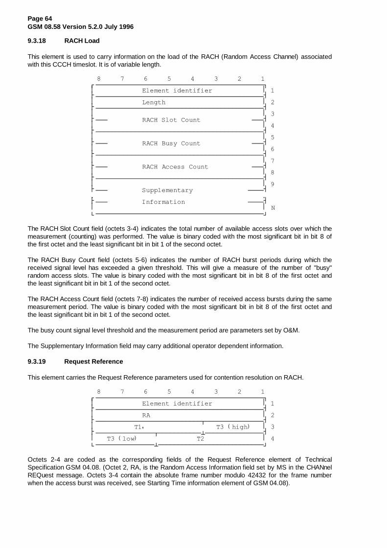
Page 64GSM 08.58 Version 5.2.0 July 1996
9.3.18 RACH Load
This element is used to carry information on the load of the RACH (Random Access Channel) associatedwith this CCCH timeslot. It is of variable length.
��������������������������������������������¸¶¶¶¶¶¶¶¶¶¶¶¶¶¶¶¶¶¶¶¶¶¶¶¶¶¶¶¶¶¶¶¶¶¶¶¶¶¶¶¶¶¶¶¹
��·������������(OHPHQW�LGHQWLILHU�������������·��¼¶¶¶¶¶¶¶¶¶¶¶¶¶¶¶¶¶¶¶¶¶¶¶¶¶¶¶¶¶¶¶¶¶¶¶¶¶¶¶¶¶¶¶½
��·������������/HQJWK�������������������������·��¼¶¶¶¶¶¶¶¶¶¶¶¶¶¶¶¶¶¶¶¶¶¶¶¶¶¶¶¶¶¶¶¶¶¶¶¶¶¶¶¶¶¶¶½
��·�������������������������������������������·��¼¶¶¶���������5$&+�6ORW�&RXQW�������������¶¶¶½
��·�������������������������������������������·��¼¶¶¶¶¶¶¶¶¶¶¶¶¶¶¶¶¶¶¶¶¶¶¶¶¶¶¶¶¶¶¶¶¶¶¶¶¶¶¶¶¶¶¶½
��·�������������������������������������������·��¼¶¶¶���������5$&+�%XV\�&RXQW�������������¶¶¶½
��·�������������������������������������������·��¼¶¶¶¶¶¶¶¶¶¶¶¶¶¶¶¶¶¶¶¶¶¶¶¶¶¶¶¶¶¶¶¶¶¶¶¶¶¶¶¶¶¶¶½
��·�������������������������������������������·��¼¶¶¶���������5$&+�$FFHVV�&RXQW�����������¶¶¶½
��·�������������������������������������������·��¼¶¶¶¶¶¶¶¶¶¶¶¶¶¶¶¶¶¶¶¶¶¶¶¶¶¶¶¶¶¶¶¶¶¶¶¶¶¶¶¶¶¶¶½
��·�������������������������������������������·��¼¶¶¶���������6XSSOHPHQWDU\��������������¶¶¶¶½���������������������������������������������¼¶¶¶���������,QIRUPDWLRQ����������������¶¶¶¶½
��·�������������������������������������������·�1º¶¶¶¶¶¶¶¶¶¶¶¶¶¶¶¶¶¶¶¶¶¶¶¶¶¶¶¶¶¶¶¶¶¶¶¶¶¶¶¶¶¶¶»
The RACH Slot Count field (octets 3-4) indicates the total number of available access slots over which themeasurement (counting) was performed. The value is binary coded with the most significant bit in bit 8 ofthe first octet and the least significant bit in bit 1 of the second octet.
The RACH Busy Count field (octets 5-6) indicates the number of RACH burst periods during which thereceived signal level has exceeded a given threshold. This will give a measure of the number of "busy"random access slots. The value is binary coded with the most significant bit in bit 8 of the first octet andthe least significant bit in bit 1 of the second octet.
The RACH Access Count field (octets 7-8) indicates the number of received access bursts during the samemeasurement period. The value is binary coded with the most significant bit in bit 8 of the first octet andthe least significant bit in bit 1 of the second octet.
The busy count signal level threshold and the measurement period are parameters set by O&M.
The Supplementary Information field may carry additional operator dependent information.
9.3.19 Request Reference
This element carries the Request Reference parameters used for contention resolution on RACH.
��������������������������������������������¸¶¶¶¶¶¶¶¶¶¶¶¶¶¶¶¶¶¶¶¶¶¶¶¶¶¶¶¶¶¶¶¶¶¶¶¶¶¶¶¶¶¶¶¹
��·������������(OHPHQW�LGHQWLILHU�������������·��¼¶¶¶¶¶¶¶¶¶¶¶¶¶¶¶¶¶¶¶¶¶¶¶¶¶¶¶¶¶¶¶¶¶¶¶¶¶¶¶¶¶¶¶½
��·������������5$�����������������������������·��¼¶¶¶¶¶¶¶¶¶¶¶¶¶¶¶¶¶¶¶¶¶¶¶¶¶¶¶¾¶¶¶¶¶¶¶¶¶¶¶¶¶¶¶½
��·����������7�������������������7���KLJK����·��¼¶¶¶¶¶¶¶¶¶¶¶¶¶¶¶¾¶¶¶¶¶¶¶¶¶¶¶¿¶¶¶¶¶¶¶¶¶¶¶¶¶¶¶½
��·���7���ORZ����������������7����������������·��º¶¶¶¶¶¶¶¶¶¶¶¶¶¶¶¿¶¶¶¶¶¶¶¶¶¶¶¶¶¶¶¶¶¶¶¶¶¶¶¶¶¶¶»
Octets 2-4 are coded as the corresponding fields of the Request Reference element of TechnicalSpecification GSM 04.08. (Octet 2, RA, is the Random Access Information field set by MS in the CHANnelREQuest message. Octets 3-4 contain the absolute frame number modulo 42432 for the frame numberwhen the access burst was received, see Starting Time information element of GSM 04.08).

Page 65GSM 08.58 Version 5.2.0 July 1996
9.3.20 Release Mode
This element is used to distinguish between normal release and local end release of the radio data linkconnection.
��������������������������������������������¸¶¶¶¶¶¶¶¶¶¶¶¶¶¶¶¶¶¶¶¶¶¶¶¶¶¶¶¶¶¶¶¶¶¶¶¶¶¶¶¶¶¶¶¹
��·������������(OHPHQW�LGHQWLILHU�������������·��¼¶¶¶¶¶¶¶¶¶¶¶¶¶¶¶¶¶¶¶¶¶¶¶¶¶¶¶¶¶¶¶¶¶¶¶¶¶¶¶¾¶¶¶½
��·�����5HVHUYHG�IRU�IXWXUH�XVH�����������·�0�·��º¶¶¶¶¶¶¶¶¶¶¶¶¶¶¶¶¶¶¶¶¶¶¶¶¶¶¶¶¶¶¶¶¶¶¶¶¶¶¶»¶¶¶»
The M bit is coded as follows:
0 normal release
1 local end release
9.3.21 Resource Information
This element is used to indicate the interference level for each of the idle channels of a TRX.
��������������������������������������������¸¶¶¶¶¶¶¶¶¶¶¶¶¶¶¶¶¶¶¶¶¶¶¶¶¶¶¶¶¶¶¶¶¶¶¶¶¶¶¶¶¶¶¶¹
��·������������(OHPHQW�LGHQWLILHU�������������·��¼¶¶¶¶¶¶¶¶¶¶¶¶¶¶¶¶¶¶¶¶¶¶¶¶¶¶¶¶¶¶¶¶¶¶¶¶¶¶¶¶¶¶¶½
��·������������/HQJWK�������������������������·��¼¶¶¶¶¶¶¶¶¶¶¶¶¶¶¶¶¶¶¶¶¶¶¶¶¶¶¶¶¶¶¶¶¶¶¶¶¶¶¶¶¶¶¶½
��·������������&KDQQHO�1XPEHU�����������������·��¼¶¶¶¶¶¶¶¶¶¶¶¶¶¶¶¶¶¶¶����¶¶¶¶¶¶¶¶¶¶¶¶¶¶¶¶¶¶¶¶½
��·������������,QWHUIHUHQFH�OHYHO�������������·��¼¶¶¶¶¶¶¶¶¶¶¶¶¶¶¶¶¶¶¶¶¶¶¶¶¶¶¶¶¶¶¶¶¶¶¶¶¶¶¶¶¶¶¶½������������������������������������������������������������������������������������������¼¶¶¶¶¶¶¶¶¶¶¶¶¶¶¶¶¶¶¶¶¶¶¶¶¶¶¶¶¶¶¶¶¶¶¶¶¶¶¶¶¶¶¶½
����·������������&KDQQHO�1XPEHU��1��������������·�1¶�¼¶¶¶¶¶¶¶¶¶¶¶¶¶¶¶¶¶¶¶����¶¶¶¶¶¶¶¶¶¶¶¶¶¶¶¶¶¶¶¶½
��·������������,QWHUIHUHQFH�OHYHO��1����������·�1º¶¶¶¶¶¶¶¶¶¶¶¶¶¶¶¶¶¶¶¶¶¶¶¶¶¶¶¶¶¶¶¶¶¶¶¶¶¶¶¶¶¶¶»
The Length field indicates in binary the remaining length of the element (octets 3-N).
Octets 3-N forms a list of Channel Numbers and Interference levels measured on the correspondingchannel.
The Channel Number octet is coded as octet 2 of the Channel Number information element, section 9.3.1.
The Interference Level octet is coded as follows:
��������������������������������������������¸¶¶¶¶¶¶¶¶¶¶¶¶¶¶¶¾¶¶¶¶¶¶¶¶¶¶¶¶¶¶¶¶¶¶¶¶¶¶¶¶¶¶¶¹·��,QWHUI�%DQG��·��5HVHUYHG�IRU�IXWXUH�XVH��·º¶¶¶¶¶¶¶¶¶¶¶¶¶¶¶¿¶¶¶¶¶¶¶¶¶¶¶¶¶¶¶¶¶¶¶¶¶¶¶¶¶¶¶»
The Interf Band field (bits 6-8) indicates in binary the interference level expressed as one of five possibleinterference level bands as defined by O&M. The interference level is averaged over a period of Intave(parameter set by O&M, see TS GSM 05.08) immediately before the transmission of the RF RESourceINDication message. See also Technical Specification GSM 08.08, section 3.1.3.1 and TechnicalSpecification GSM 05.08, section 3.1 e) of Appendix A.

Page 66GSM 08.58 Version 5.2.0 July 1996
9.3.22 RLM Cause
This element is used to indicate the precise protocol error or the reason for a release on the radio linklayer.
��������������������������������������������¸¶¶¶¶¶¶¶¶¶¶¶¶¶¶¶¶¶¶¶¶¶¶¶¶¶¶¶¶¶¶¶¶¶¶¶¶¶¶¶¶¶¶¶¹
��·������������(OHPHQW�LGHQWLILHU�������������·��¼¶¶¶¶¶¶¶¶¶¶¶¶¶¶¶¶¶¶¶¶¶¶¶¶¶¶¶¶¶¶¶¶¶¶¶¶¶¶¶¶¶¶¶½
��·������������/HQJWK�������������������������·��¼¶¶¶¾¶¶¶¶¶¶¶¶¶¶¶¶¶¶¶¶¶¶¶¶¶¶¶¶¶¶¶¶¶¶¶¶¶¶¶¶¶¶¶½
��·�(����������&DXVH�9DOXH��������������������·��º¶¶¶¿¶¶¶¶¶¶¶¶¶¶¶¶¶¶¶¶¶¶¶¶¶¶¶¶¶¶¶¶¶¶¶¶¶¶¶¶¶¶¶»
The Cause Value is a one octet field if the extension bit is set to 0. If the extension bit is set to 1, theCause Value is a two octet field.
The Cause Value field is coded as follows:
8 7 6 5 4 3 2 1
0 0 0 0 0 0 0 0 reserved
0 0 0 0 0 0 0 1 timer T200 expired (N200+1) times
0 0 0 0 0 0 1 0 re-establishment request
0 0 0 0 0 0 1 1 unsolicited UA response
0 0 0 0 0 1 0 0 unsolicited DM response
0 0 0 0 0 1 0 1 unsolicated DM response, multiple frame established state
0 0 0 0 0 1 1 0 unsolicited supervisory response
0 0 0 0 0 1 1 1 sequence error
0 0 0 0 1 0 0 0 U-frame with incorrect parameters
0 0 0 0 1 0 0 1 S-frame with incorrect parameters
0 0 0 0 1 0 1 0 I-frame with incorrect use of M bit
0 0 0 0 1 0 1 1 I-frame with incorrect length
0 0 0 0 1 1 0 0 frame not implemented
0 0 0 0 1 1 0 1 SABM command, multiple frame established state
0 0 0 0 1 1 1 0 SABM frame with information not allowed in this state
All other values are reserved for future use.

Page 67GSM 08.58 Version 5.2.0 July 1996
9.3.23 Starting Time
This element provides the starting time expressed as FN modulo 42432 (FN is absolute frame number).
��������������������������������������������¸¶¶¶¶¶¶¶¶¶¶¶¶¶¶¶¶¶¶¶¶¶¶¶¶¶¶¶¶¶¶¶¶¶¶¶¶¶¶¶¶¶¶¶¹
��·������������(OHPHQW�LGHQWLILHU�������������·��¼¶¶¶¶¶¶¶¶¶¶¶¶¶¶¶¶¶¶¶¶¶¶¶¶¶¶¶¾¶¶¶¶¶¶¶¶¶¶¶¶¶¶¶½
��·����������7�������������������7���KLJK����·��¼¶¶¶¶¶¶¶¶¶¶¶¶¶¶¶¾¶¶¶¶¶¶¶¶¶¶¶¿¶¶¶¶¶¶¶¶¶¶¶¶¶¶¶½
��·���7���ORZ����������������7����������������·��º¶¶¶¶¶¶¶¶¶¶¶¶¶¶¶¿¶¶¶¶¶¶¶¶¶¶¶¶¶¶¶¶¶¶¶¶¶¶¶¶¶¶¶»
Octets 2-3 are coded as defined for octets 2-3 of the Starting Time information element of TechnicalSpecification GSM 04.08.
9.3.24 Timing Advance
This element contains the timing advance to be used by MS in subsequent communications. It is calculatedby BTS at the reception of a CHANnel REQuest message (random access burst) or a handover accessburst.
��������������������������������������������¸¶¶¶¶¶¶¶¶¶¶¶¶¶¶¶¶¶¶¶¶¶¶¶¶¶¶¶¶¶¶¶¶¶¶¶¶¶¶¶¶¶¶¶¹
��·������������(OHPHQW�LGHQWLILHU�������������·��¼¶¶¶¶¶¶¶¶¶¶¾¶¶¶¶¶¶¶¶¶¶¶¶¶¶¶¶¶¶¶¶¶¶¶¶¶¶¶¶¶¶¶¶½
��·�5HVHUYHG�·��������7LPLQJ�$GYDQFH����������·��º¶¶¶¶¶¶¶¶¶¶¿¶¶¶¶¶¶¶¶¶¶¶¶¶¶¶¶¶¶¶¶¶¶¶¶¶¶¶¶¶¶¶¶»
The Timing Advance field contains the timing advance TA as specified in Technical SpecificationGSM 05.10.
Bits 7-8 of octet 2 are reserved for future use.
9.3.25 Uplink Measurements
This element is used to report the results of the TRX measurements on the uplink radio path of anactivated basic radio channel. It is of variable length.
��������������������������������������������¸¶¶¶¶¶¶¶¶¶¶¶¶¶¶¶¶¶¶¶¶¶¶¶¶¶¶¶¶¶¶¶¶¶¶¶¶¶¶¶¶¶¶¶¹
��·������������(OHPHQW�LGHQWLILHU�������������·��¼¶¶¶¶¶¶¶¶¶¶¶¶¶¶¶¶¶¶¶¶¶¶¶¶¶¶¶¶¶¶¶¶¶¶¶¶¶¶¶¶¶¶¶½
��·������������/HQJWK�������������������������·��¼¶¶¶¾¶¶¶¶¶¾¶¶¶¶¶¶¶¶¶¶¶¶¶¶¶¶¶¶¶¶¶¶¶¶¶¶¶¶¶¶¶¶¶½
��·UIX·�'7;G·�������5;/(9¶)8//¶XS�������������·��¼¶¶¶¿¶¶¶¶¶À¶¶¶¶¶¶¶¶¶¶¶¶¶¶¶¶¶¶¶¶¶¶¶¶¶¶¶¶¶¶¶¶¶½
��·�5HVHUYHG·�������5;/(9¶68%¶XS��������������·��¼¶¶¶¶¶¶¶¶¶À¶¶¶¶¶¶¶¶¶¶¶¶¶¶¶¶¶¾¶¶¶¶¶¶¶¶¶¶¶¶¶¶¶½
��·�5HVHUYHG·�5;48$/¶)8//¶XS��·5;48$/¶68%¶XS��·��¼¶¶¶¶¶¶¶¶¶¿¶¶¶¶¶¶¶¶¶¶¶¶¶¶¶¶¶¿¶¶¶¶¶¶¶¶¶¶¶¶¶¶¶½
��·�������������6XSSOHPHQWDU\�����������������·��¼¶¶¶�������������������������������������¶¶¶½��������������0HDVXUHPHQW��������������������¼¶¶¶�������������������������������������¶¶¶½
��·�������������,QIRUPDWLRQ�������������������·�1º¶¶¶¶¶¶¶¶¶¶¶¶¶¶¶¶¶¶¶¶¶¶¶¶¶¶¶¶¶¶¶¶¶¶¶¶¶¶¶¶¶¶¶»
rfu = Reserved for Future Use.
The Length field indicates in binary the remaining length of the element (octets 3-N).
Octets 3-5 contain results from measurements made by TRX on the uplink.
The Supplementary Measurement Information field (octets 6-N) may carry additional operator dependentinformation.
The DTXd field (octet 3) indicates whether DTX was employed by TRX on the downlink transmissionduring the measurement period.

Page 68GSM 08.58 Version 5.2.0 July 1996
The RXLEV-FULL-up and RXLEV-SUB-up fields (octets 3-4) report the average uplink signal level asmeasured by TRX over the measurement period on all slots and on a subset of the slots respectively (seeTechnical Specification GSM 05.08, section 8.2). Each field is coded as defined in Technical SpecificationGSM 05.08, section 8.1.4.
The RXQUAL-FULL-up and RXQUAL-SUB-up fields (octet 5) report the average uplink quality asmeasured by TRX over the measurement period on all slots and on a subset of the slots respectively (seeTechnical Specification GSM 05.08, section 8.2). Each field is coded as defined in Technical SpecificationGSM 05.08, section 8.2.4.
9.3.26 Cause
The cause element is used to indicate the reason for a particular event to have occurred and is coded asshown below.
��������������������������������������������¸¶¶¶¶¶¶¶¶¶¶¶¶¶¶¶¶¶¶¶¶¶¶¶¶¶¶¶¶¶¶¶¶¶¶¶¶¶¶¶¶¶¶¶¹
��·������������(OHPHQW�LGHQWLILHU�������������·��¼¶¶¶¶¶¶¶¶¶¶¶¶¶¶¶¶¶¶¶¶¶¶¶¶¶¶¶¶¶¶¶¶¶¶¶¶¶¶¶¶¶¶¶½
��·������������/HQJWK�������������������������·��¼¶¶¶¾¶¶¶¶¶¶¶¶¶¶¶¶¶¶¶¶¶¶¶¶¶¶¶¶¶¶¶¶¶¶¶¶¶¶¶¶¶¶¶½
��·�(����������&DXVH�9DOXH��������������������·��¼¶¶¶¿¶¶¶¶¶¶¶¶¶¶¶¶¶¶¶¶¶¶¶¶¶¶¶¶¶¶¶¶¶¶¶¶¶¶¶¶¶¶¶½
���·������������&DXVH�([WHQVLRQ����������������·��D¼¶¶¶¶¶¶¶¶¶¶¶¶¶¶¶¶¶¶¶¶¶¶¶¶¶¶¶¶¶¶¶¶¶¶¶¶¶¶¶¶¶¶¶½
��·�������������������������������������������·��¼¶¶¶¶¶��������������������������������¶¶¶¶¶¶½�������������'LDJQRVWLF�V��LI�DQ\������������¼¶¶¶¶¶��������������������������������¶¶¶¶¶¶½
��·�������������������������������������������·�1º¶¶¶¶¶¶¶¶¶¶¶¶¶¶¶¶¶¶¶¶¶¶¶¶¶¶¶¶¶¶¶¶¶¶¶¶¶¶¶¶¶¶¶»
The Length field indicates in binary the remaining length of the element (octets 3-N).
The Cause Value is a single octet field (octet 3) if the extension bit E (bit 8) is set to 0. If it is set to 1 thenthe cause value is a 2 octet field (octets 3 and 3a).
The Cause Value is divided into two fields: a class (bits 5-7 of octet 3) and a value within the class(bits 1-4 of octet 3).
If the value of the first octet of the cause field is 1XXX 0000 then the second octet is reserved for nationalapplications (XXX will still indicate the class).
Diagnostic information is not available for every cause, see the table below. When available, it is coded inthe same way as the corresponding information element in section 9. Inclusion of diagnostics is optional.
Classes:
Class (000) : Normal event
Class (001) : Normal event
Class (010) : Resource unavailable
Class (011) : Service or option not available
Class (100) : Service or option not implemented
Class (101) : Invalid message (e.g. parameter out of range)
Class (110) : Protocol error
Class (111) : Interworking

Page 69GSM 08.58 Version 5.2.0 July 1996
CAUSE VALUES:
&ODVV�·�9DOXH���·�&DXVH�������������������������·'LDJQRVWLFV������·���������·�������������������������������·������·���������·�1RUPDO�(YHQW������������������·������·���������·�������������������������������·������·���������·�UDGLR�LQWHUIDFH�IDLOXUH�������·&KDQQHO�1XPEHU������·���������·�UDGLR�OLQN�IDLOXUH������������·&KDQQHO�1XPEHU������·���������·�KDQGRYHU�DFFHVV�IDLOXUH�������·&KDQQHO�1XPEHU������·���������·�UHVHUYHG�IRU�LQWHUQDWLRQDO�XVH·������·���������·�UHVHUYHG�IRU�LQWHUQDWLRQDO�XVH·������·���������·�UHVHUYHG�IRU�LQWHUQDWLRQDO�XVH·������·���������·�UHVHUYHG�IRU�LQWHUQDWLRQDO�XVH·������·���������·�20�LQWHUYHQWLRQ��������������·������·���������·�������������������������������·������·���������·�UHVHUYHG�IRU�LQWHUQDWLRQDO�XVH·������·���������·�������������������������������·������·���������·�������������������������������·������·���������·�������������������������������·������·���������·�QRUPDO�HYHQW��XQVSHFLILHG�����·������·���������·�������������������������������·¶¶¶¶¶¶À¶¶¶¶¶¶¶¶¶À¶¶¶¶¶¶¶¶¶¶¶¶¶¶¶¶¶¶¶¶¶¶¶¶¶¶¶¶¶¶¶À¶¶¶¶¶¶¶¶¶¶¶¶¶¶¶������·���������·�������������������������������·������·���������·�1RUPDO�(YHQW������������������·������·���������·�������������������������������·������·���������·�UHVHUYHG�IRU�LQWHUQDWLRQDO�XVH·������·���������·�������������������������������·������·���������·�������������������������������·������·���������·�������������������������������·������·���������·�UHVHUYHG�IRU�QDWLRQDO�XVH�����·������·���������·�������������������������������·������·���������·�������������������������������·������·���������·�������������������������������·¶¶¶¶¶¶À¶¶¶¶¶¶¶¶¶À¶¶¶¶¶¶¶¶¶¶¶¶¶¶¶¶¶¶¶¶¶¶¶¶¶¶¶¶¶¶¶À¶¶¶¶¶¶¶¶¶¶¶¶¶¶¶������·���������·�������������������������������·������·���������·�5HVRXUFH�XQDYDLODEOH����������·������·���������·�������������������������������·������·���������·�HTXLSPHQW�IDLOXUH�������������·������·���������·�UDGLR�UHVRXUFH�QRW�DYDLODEOH��·&KDQQHO�1XPEHU������·���������·�WHUUHVWULDO�FKDQQHO�IDLOXUH���·&KDQQHO�1XPEHU������·���������·�&&&+�RYHUORDG�����������������·&KDQQHO�1XPEHU������·���������·�$&&+�RYHUORDG�����������������·&KDQQHO�1XPEHU������·���������·�SURFHVVRU�RYHUORDG������������·������·���������·�UHVHUYHG�IRU�LQWHUQDWLRQDO�XVH·������·���������·�%76�QRW�HTXLSSHG��������������·������·���������·�UHPRWH�WUDQVFRGHU�IDLOXUH�����·&KDQQHO�1XPEHU������·���������·�UHVHUYHG�IRU�LQWHUQDWLRQDO�XVH·������·���������·�UHVHUYHG�IRU�LQWHUQDWLRQDO�XVH·������·���������·�UHVHUYHG�IRU�LQWHUQDWLRQDO�XVH·������·���������·�UHVHUYHG�IRU�QDWLRQDO�XVH�����·������·���������·�UHVHUYHG�IRU�QDWLRQDO�XVH�����·������·���������·�UHVHUYHG�IRU�QDWLRQDO�XVH�����·������·���������·�UHVRXUFH�QRW�DYDLODEOH��������·������·���������·�XQVSHFLILHG�������������������·

Page 70GSM 08.58 Version 5.2.0 July 1996
&ODVV�·�9DOXH���·�&DXVH�������������������������·�'LDJQRVWLFV������·���������·�������������������������������·������·���������·�6HUYLFH�RU�2SWLRQ�1RW���������·������·���������·�$YDLODEOH���������������������·������·���������·�������������������������������·������·���������·�UHTXHVWHG�WUDQVFRGLQJ�UDWH����·&KDQQHO�1XPEHU������·���������·�DGDSWLRQ�QRW�DYDLODEOH��������·������·���������·�������������������������������·������·���������·�UHVHUYHG�IRU�LQWHUQDWLRQDO�XVH·������·���������·�������������������������������·������·���������·�������������������������������·������·���������·�������������������������������·������·���������·�VHUYLFH�RU�RSWLRQ�QRW���������·������·���������·�DYDLODEOH��XQVSHFLILHG��������·������·���������·�������������������������������·¶¶¶¶¶¶À¶¶¶¶¶¶¶¶¶À¶¶¶¶¶¶¶¶¶¶¶¶¶¶¶¶¶¶¶¶¶¶¶¶¶¶¶¶¶¶¶À¶¶¶¶¶¶¶¶¶¶¶¶¶¶¶������·���������·�������������������������������·������·���������·�6HUYLFH�RU�2SWLRQ�1RW���������·������·���������·�,PSOHPHQWHG�������������������·������·���������·�������������������������������·������·���������·�HQFU\SWLRQ�DOJRULWKP�QRW������·&KDQQHO�1XPEHU������·���������·�LPSOHPHQWHG�������������������·������·���������·�������������������������������·������·���������·�UHVHUYHG�IRU�LQWHUQDWLRQDO�XVH·������·���������·�������������������������������·������·���������·�������������������������������·������·���������·�������������������������������·������·���������·�UHVHUYHG�IRU�QDWLRQDO�XVH�����·������·���������·�������������������������������·������·���������·�������������������������������·������·���������·�������������������������������·������·���������·�VHUYLFH�RU�RSWLRQ�QRW���������·������·���������·�LPSOHPHQWHG��XQVSHFLILHG������·������·���������·�������������������������������·¶¶¶¶¶¶À¶¶¶¶¶¶¶¶¶À¶¶¶¶¶¶¶¶¶¶¶¶¶¶¶¶¶¶¶¶¶¶¶¶¶¶¶¶¶¶¶À¶¶¶¶¶¶¶¶¶¶¶¶¶¶¶������·���������·�������������������������������·������·���������·�,QYDOLG�0HVVDJH���������������·������·���������·�������������������������������·������·���������·�UDGLR�FKDQQHO�DOUHDG\���������·&KDQQHO�1XPEHU������·���������·�DFWLYDWHG�DOORFDWHG�����������·������·���������·�������������������������������·������·���������·�UHVHUYHG�IRU�LQWHUQDWLRQDO�XVH·������·���������·�������������������������������·������·���������·�������������������������������·������·���������·�������������������������������·������·���������·�UHVHUYHG�IRU�QDWLRQDO�XVH�����·������·���������·�������������������������������·������·���������·�������������������������������·������·���������·�������������������������������·������·���������·�LQYDOLG�PHVVDJH��XQVSHFLILHG��·������·���������·�������������������������������·

Page 71GSM 08.58 Version 5.2.0 July 1996
&ODVV�·�9DOXH���·�&DXVH�������������������������·�'LDJQRVWLFV������·���������·�������������������������������·������·���������·�3URWRFRO�(UURU����������������·������·���������·�������������������������������·������·���������·�PHVVDJH�GLVFULPLQDWRU�HUURU���·0HVVDJH�'LVFULP������·���������·�PHVVDJH�W\SH�HUURU������������·0HVVDJH�7\SH������·���������·�PHVVDJH�VHTXHQFH�HUURU��������·0HVVDJH�7\SH������·���������·�JHQHUDO�LQIRUPDWLRQ�HOHPHQW���·������·���������·�HUURU�������������������������·������·���������·�PDQGDWRU\�LQIRUPDWLRQ�HOHPHQW�·(OHPHQW�,GHQWLI������·���������·�HUURU�������������������������·������·���������·�RSWLRQDO�LQIRUPDWLRQ�HOHPHQW��·(OHPHQW�,GHQWLI������·���������·�HUURU�������������������������·������·���������·�LQIRUPDWLRQ�HOHPHQW�����������·(OHPHQW�,GHQWLI������·���������·�QRQ�H[LVWHQW������������������·������·���������·�LQIRUPDWLRQ�HOHPHQW�OHQJWK����·(OHPHQW�,GHQWLI������·���������·�HUURU�������������������������·������·���������·�LQYDOLG�LQIRUPDWLRQ�HOHPHQW���·,QIRUP��(OHPHQW������·���������·�FRQWHQWV����������������������·������·���������·�UHVHUYHG�IRU�LQWHUQDWLRQDO�XVH·������·���������·�UHVHUYHG�IRU�LQWHUQDWLRQDO�XVH·������·���������·�UHVHUYHG�IRU�LQWHUQDWLRQDO�XVH·������·���������·�UHVHUYHG�IRU�QDWLRQDO�XVH�����·������·���������·�UHVHUYHG�IRU�QDWLRQDO�XVH�����·������·���������·�UHVHUYHG�IRU�QDWLRQDO�XVH�����·������·���������·�SURWRFRO�HUURU��XQVSHFLILHG���·������·���������·�������������������������������·¶¶¶¶¶¶À¶¶¶¶¶¶¶¶¶À¶¶¶¶¶¶¶¶¶¶¶¶¶¶¶¶¶¶¶¶¶¶¶¶¶¶¶¶¶¶¶À¶¶¶¶¶¶¶¶¶¶¶¶¶¶¶������·���������·�������������������������������·������·���������·�,QWHUZRUNLQJ������������������·������·���������·�������������������������������·������·���������·�UHVHUYHG�IRU�LQWHUQDWLRQDO�XVH·������·���������·�������������������������������·������·���������·�������������������������������·������·���������·�������������������������������·������·���������·�UHVHUYHG�IRU�QDWLRQDO�XVH�����·������·���������·�������������������������������·������·���������·�������������������������������·������·���������·�������������������������������·������·���������·�LQWHUZRUNLQJ��XQVSHFLILHG�����·������·���������·�������������������������������·

Page 72GSM 08.58 Version 5.2.0 July 1996
9.3.27 Measurement result number
This element is used by BTS to number, (on a channel), the measurement result messages sent to BSC. Itis set to 0 at activation time of the channel. The numbering is modulo 256.
��������������������������������������������¸¶¶¶¶¶¶¶¶¶¶¶¶¶¶¶¶¶¶¶¶¶¶¶¶¶¶¶¶¶¶¶¶¶¶¶¶¶¶¶¶¶¶¶¹
��·������������(OHPHQW�LGHQWLILHU�������������·��¼¶¶¶¶¶¶¶¶¶¶¶¶¶¶¶¶¶¶¶¶¶¶¶¶¶¶¶¶¶¶¶¶¶¶¶¶¶¶¶¶¶¶¶½
��·��������0HDVXUHPHQW�UHVXOW�QXPEHU����������·��º¶¶¶¶¶¶¶¶¶¶¶¶¶¶¶¶¶¶¶¶¶¶¶¶¶¶¶¶¶¶¶¶¶¶¶¶¶¶¶¶¶¶¶»
9.3.28 Message Identifier
This element is used to indicate a message type within a message.
��������������������������������������������¸¶¶¶¶¶¶¶¶¶¶¶¶¶¶¶¶¶¶¶¶¶¶¶¶¶¶¶¶¶¶¶¶¶¶¶¶¶¶¶¶¶¶¶¹
��·������������(OHPHQW�LGHQWLILHU�������������·��¼¶¶¶¶¶¶¶¶¶¶¶¶¶¶¶¶¶¶¶¶¶¶¶¶¶¶¶¶¶¶¶¶¶¶¶¶¶¶¶¶¶¶¶½
��·������������0HVVDJH�7\SH�������������������·��º¶¶¶¶¶¶¶¶¶¶¶¶¶¶¶¶¶¶¶¶¶¶¶¶¶¶¶¶¶¶¶¶¶¶¶¶¶¶¶¶¶¶¶»
Octet 2 is coded as the Message Type information element, section 9.2.
9.3.29 SACCH Information
This element is used to carry the SACCH filling information (System Information messages) that is to beused on a specific channel.
�������������������������������������������¸¶¶¶¶¶¶¶¶¶¶¶¶¶¶¶¶¶¶¶¶¶¶¶¶¶¶¶¶¶¶¶¶¶¶¶¶¶¶¶¶¶¶¶¹
��·������������(OHPHQW�LGHQWLILHU�������������·��¼¶¶¶¶¶¶¶¶¶¶¶¶¶¶¶¶¶¶¶¶¶¶¶¶¶¶¶¶¶¶¶¶¶¶¶¶¶¶¶¶¶¶¶½
��·������������/HQJWK�������������������������·��¼¶¶¶¶¶¶¶¶¶¶¶¶¶¶¶¶¶¶¶¶¶¶¶¶¶¶¶¶¶¶¶¶¶¶¶¶¶¶¶¶¶¶¶½
��·������������1XPEHU�RI�6,�PHVVDJHV����������·��¼¶¶¶¶¶¶¶¶¶¶¶¶¶¶¶¶¶¶¶¶¶¾¶¶¶¶¶¶¶¶¶¶¶¶¶¶¶¶¶¶¶¶¶½
��·�����5HVHUYHG��������·���7\SH�RI��VW�6,�PVJ·��¼¶¶¶¶¶¶¶¶¶¶¶¶¶¶¶¶¶¶¶¶¶¿¶¶¶¶¶¶¶¶¶¶¶¶¶¶¶¶¶¶¶¶¶½
��·������������/HQJWK�RI��VW�6,�PHVVDJH�������·��¼¶¶¶¶¶¶¶¶¶¶¶¶¶¶¶¶¶¶¶¶¶¶¶¶¶¶¶¶¶¶¶¶¶¶¶¶¶¶¶¶¶¶¶½·�������������������������������������������·¼¶¶¶����������VW�6,�PHVVDJH�������������¶¶¶¶½
������������������������������������������������M¼¶¶¶¶¶¶¶¶¶¶¶¶¶¶¶¶¶¶¶¶¶¶¶¶¶¶¶¶¶¶¶¶¶¶¶¶¶¶¶¶¶¶¶½������������������������������������������������������������������������������������������¼¶¶¶¶¶¶¶¶¶¶¶¶¶¶¶¶¶¶¶¶¶¾¶¶¶¶¶¶¶¶¶¶¶¶¶¶¶¶¶¶¶¶¶½
��·�����5HVHUYHG��������·��7\SH�RI�QWK�6,�PVJ·�O¼¶¶¶¶¶¶¶¶¶¶¶¶¶¶¶¶¶¶¶¶¶¿¶¶¶¶¶¶¶¶¶¶¶¶¶¶¶¶¶¶¶¶¶½
����·������������/HQJWK�RI�QWK�6,�PHVVDJH������·�O��¼¶¶¶¶¶¶¶¶¶¶¶¶¶¶¶¶¶¶¶¶¶¶¶¶¶¶¶¶¶¶¶¶¶¶¶¶¶¶¶¶¶¶¶½
��·�������������������������������������������·�1¼¶¶¶���������QWK�6,�PHVVJH�������������¶¶¶¶½���������������������������������������������º¶¶¶¶¶¶¶¶¶¶¶¶¶¶¶¶¶¶¶¶¶¶¶¶¶¶¶¶¶¶¶¶¶¶¶¶¶¶¶¶¶¶¶»
The Length field (octet 2) indicates in binary the total remaining length of the element (octets 3 - N).
The Number of SI messages field (octet 3) indicates in binary the number of System Information messagescontained in the element.
The coding of each of these messages consists of a SI type field (Type of n’th SI msg), a length field(Length of n’th SI message) and a message field (n’th SI message).

Page 73GSM 08.58 Version 5.2.0 July 1996
The "Type of n’th msg" field indicates the type of SYSTEM INFORMATION that follows in the "n’th SImessage" field. It is coded as follows:
Value System information message0101 SYSTEM INFORMATION 50110 SYSTEM INFORMATION 61101 SYSTEM INFORMATION 5bis1110 SYSTEM INFORMATION 5ter
All other values are reserved.
The "Length of n’th SI message" field indicates in binary the length of the "n’th SI message" field thatfollows.
The "n’th SI message" field contains a complete SACCH System Information message as defended in TSGSM 04.08.
9.3.30 System Info Type
This element is used to indicate the type of SYSTEM INFORMATION message as defined in TechnicalSpecification GSM 04.08 (SYSTEM INFORMATION 1 through 8).
��������������������������������������������¸¶¶¶¶¶¶¶¶¶¶¶¶¶¶¶¶¶¶¶¶¶¶¶¶¶¶¶¶¶¶¶¶¶¶¶¶¶¶¶¶¶¶¶¹
��·������������(OHPHQW�LGHQWLILHU�������������·��¼¶¶¶¶¶¶¶¶¶¶¶¶¶¶¶¶¶¶¶¶¶¾¶¶¶¶¶¶¶¶¶¶¶¶¶¶¶¶¶¶¶¶¶½
��·�����5HVHUYHG��������·���6\V�,QIR�7\SH�����·��º¶¶¶¶¶¶¶¶¶¶¶¶¶¶¶¶¶¶¶¶¶¿¶¶¶¶¶¶¶¶¶¶¶¶¶¶¶¶¶¶¶¶¶»
The Sys Info Field (bits 1-4 of octet 2) indicates the SYSTEM INFORMATION message. It is coded asfollows:
Value System information message
0 0 0 0 SYSTEM INFORMATION 8 0 0 0 1 SYSTEM INFORMATION 1 0 0 1 0 SYSTEM INFORMATION 2 0 0 1 1 SYSTEM INFORMATION 3 0 1 0 0 SYSTEM INFORMATION 4 0 1 0 1 SYSTEM INFORMATION 5 0 1 1 0 SYSTEM INFORMATION 6 0 1 1 1 SYSTEM INFORMATION 7 1 0 1 0 SYSTEM INFORMATION 2bis 1 0 1 1 SYSTEM INFORMATION 2ter 1 1 0 1 SYSTEM INFORMATION 5bis 1 1 1 0 SYSTEM INFORMATION 5ter
All other values are reserved.

Page 74GSM 08.58 Version 5.2.0 July 1996
9.3.31 MS Power Parameters
This element carries the parameters required by TRX for MS power control.
��������������������������������������������¸¶¶¶¶¶¶¶¶¶¶¶¶¶¶¶¶¶¶¶¶¶¶¶¶¶¶¶¶¶¶¶¶¶¶¶¶¶¶¶¶¶¶¶¹
��·������������(OHPHQW�LGHQWLILHU�������������·��¼¶¶¶¶¶¶¶¶¶¶¶¶¶¶¶¶¶¶¶¶¶¶¶¶¶¶¶¶¶¶¶¶¶¶¶¶¶¶¶¶¶¶¶½
��·������������/HQJWK�������������������������·��¼¶¶¶¶¶¶¶¶¶¶¶¶¶¶¶¶¶¶¶¶¶¶¶¶¶¶¶¶¶¶¶¶¶¶¶¶¶¶¶¶¶¶¶½
��·�������������������������������������������·��¼¶¶¶���������06�3RZHU�&RQWURO�����������¶¶¶¶½���������������������������������������������¼¶¶¶���������3DUDPHWHUV�����������������¶¶¶¶½
��·�������������������������������������������·�1º¶¶¶¶¶¶¶¶¶¶¶¶¶¶¶¶¶¶¶¶¶¶¶¶¶¶¶¶¶¶¶¶¶¶¶¶¶¶¶¶¶¶¶»
The MS Power Control Parameters field contains the parameters and limits required when MS powercontrol is to be performed by BTS. The coding is operator dependant. Examples of possible parametersand algorithms can be found in Technical Specification GSM 05.08 (RXLEV, RX-QUAL-FULL,RX-QUAL-SUB, DISTANCE (Timing Advance) etc.).
9.3.32 BS Power Parameters
This element carries the parameters required by TRX for control of its own transmission power.
��������������������������������������������¸¶¶¶¶¶¶¶¶¶¶¶¶¶¶¶¶¶¶¶¶¶¶¶¶¶¶¶¶¶¶¶¶¶¶¶¶¶¶¶¶¶¶¶¹
��·������������(OHPHQW�LGHQWLILHU�������������·��¼¶¶¶¶¶¶¶¶¶¶¶¶¶¶¶¶¶¶¶¶¶¶¶¶¶¶¶¶¶¶¶¶¶¶¶¶¶¶¶¶¶¶¶½
��·������������/HQJWK�������������������������·��¼¶¶¶¶¶¶¶¶¶¶¶¶¶¶¶¶¶¶¶¶¶¶¶¶¶¶¶¶¶¶¶¶¶¶¶¶¶¶¶¶¶¶¶½
��·�������������������������������������������·��¼¶¶¶���������%6�3RZHU�&RQWURO�����������¶¶¶¶½���������������������������������������������¼¶¶¶���������3DUDPHWHUV�����������������¶¶¶¶½
��·�������������������������������������������·�1º¶¶¶¶¶¶¶¶¶¶¶¶¶¶¶¶¶¶¶¶¶¶¶¶¶¶¶¶¶¶¶¶¶¶¶¶¶¶¶¶¶¶¶»
The BS Power Control Parameters field contains the parameters and limits required when TRXtransmission power control is to be performed by BTS. The coding is operator dependant. Examples ofpossible parameters and algorithms can be found in Technical Specification GSM 05.08 (RXLEV,RX-QUAL-FULL, RX-QUAL-SUB, DISTANCE (Timing Advance) etc.).

Page 75GSM 08.58 Version 5.2.0 July 1996
9.3.33 Pre-processing Parameters
This element contains the parameters required by BTS for the pre- processing of radio measurement data.
��������������������������������������������¸¶¶¶¶¶¶¶¶¶¶¶¶¶¶¶¶¶¶¶¶¶¶¶¶¶¶¶¶¶¶¶¶¶¶¶¶¶¶¶¶¶¶¶¹
��·������������(OHPHQW�LGHQWLILHU�������������·��¼¶¶¶¶¶¶¶¶¶¶¶¶¶¶¶¶¶¶¶¶¶¶¶¶¶¶¶¶¶¶¶¶¶¶¶¶¶¶¶¶¶¶¶½
��·������������/HQJWK�������������������������·��¼¶¶¶¶¶¶¶¶¶¶¶¶¶¶¶¶¶¶¶¶¶¶¶¶¶¶¶¶¶¶¶¶¶¶¶¶¶¶¾¶¶¶¶½
��·���UHVHUYHG�IRU�IXWXUH�XVH������������·�3��·��¼¶¶¶¶¶¶¶¶¶¶¶¶¶¶¶¶¶¶¶¶¶¶¶¶¶¶¶¶¶¶¶¶¶¶¶¶¶¶¿¶¶¶¶½
��·�������������������������������������������·��¼¶¶¶���������3UH�SURFHVVLQJ�������������¶¶¶¶½���������������������������������������������¼¶¶¶���������3DUDPHWHUV�����������������¶¶¶¶½
��·�������������������������������������������·�1º¶¶¶¶¶¶¶¶¶¶¶¶¶¶¶¶¶¶¶¶¶¶¶¶¶¶¶¶¶¶¶¶¶¶¶¶¶¶¶¶¶¶¶»
The P bit (bit 1 of octet 3) indicates whether pre-processing is to be used and it is coded as follows:
0 use the basic measurement reporting procedure (report raw data) 1 use the pre-processed measurement reporting procedure.
If pre-processing is to be used, the Pre-processing Parameters field (octets 4-N) contains the parametersrequired by BTS. The coding of this field is operator dependant.
9.3.34 Pre-processed Measurements
This element is used by BTS to report the results of the pre-processing of radio measurement data.
��������������������������������������������¸¶¶¶¶¶¶¶¶¶¶¶¶¶¶¶¶¶¶¶¶¶¶¶¶¶¶¶¶¶¶¶¶¶¶¶¶¶¶¶¶¶¶¶¹
��·������������(OHPHQW�LGHQWLILHU�������������·��¼¶¶¶¶¶¶¶¶¶¶¶¶¶¶¶¶¶¶¶¶¶¶¶¶¶¶¶¶¶¶¶¶¶¶¶¶¶¶¶¶¶¶¶½
��·������������/HQJWK�������������������������·��¼¶¶¶¶¶¶¶¶¶¶¶¶¶¶¶¶¶¶¶¶¶¶¶¶¶¶¶¶¶¶¶¶¶¶¶¶¶¶¶¶¶¶¶½
��·�������������������������������������������·��¼¶¶¶���������3UH�SURFHVVHG��������������¶¶¶¶½���������������������������������������������¼¶¶¶���������0HDVXUHPHQWV���������������¶¶¶¶½
��·�������������������������������������������·�1º¶¶¶¶¶¶¶¶¶¶¶¶¶¶¶¶¶¶¶¶¶¶¶¶¶¶¶¶¶¶¶¶¶¶¶¶¶¶¶¶¶¶¶»
The Pre-processed Measurements field (octets 3-N) contains the results of the pre-processing in BTS. Thecoding of this field is operator dependant.
9.3.35 Full Immediate Assign Info
This element is used to convey a full L3 immediate assign message (3 types).
��������������������������������������������¸¶¶¶¶¶¶¶¶¶¶¶¶¶¶¶¶¶¶¶¶¶¶¶¶¶¶¶¶¶¶¶¶¶¶¶¶¶¶¶¶¶¶¶¹
��·������������(OHPHQW�LGHQWLILHU�������������·��¼¶¶¶¶¶¶¶¶¶¶¶¶¶¶¶¶¶¶¶¶¶¶¶¶¶¶¶¶¶¶¶¶¶¶¶¶¶¶¶¶¶¶¶½
��·������������/HQJWK�,QGLFDWRU���������������·��¼¶¶¶¶¶¶¶¶¶¶¶¶¶¶¶¶¶¶¶¶¶¶¶¶¶¶¶¶¶¶¶¶¶¶¶¶¶¶¶¶¶¶¶½
��·�������������������������������������������·��¼¶¶¶���������)XOO�,PPHGLDWH�������������¶¶¶¶½�������������$VVLJQ��������������������������¼¶¶¶���������,QIR�����������������������¶¶¶¶½
���·�������������������������������������������·���º¶¶¶¶¶¶¶¶¶¶¶¶¶¶¶¶¶¶¶¶¶¶¶¶¶¶¶¶¶¶¶¶¶¶¶¶¶¶¶¶¶¶¶»
The Length Indicator field (octet 2) indicates in binary the remaining length of the element (octets 3-25).
The Full Immediate Assign Info field (octets 3-25) contains a complete immediate assign message(IMMEDIATE ASSIGN or IMMEDIATE ASSIGN EXTENDED or IMMEDIATE ASSIGN REJECT) asdefined in Technical Specification GSM 04.08.

Page 76GSM 08.58 Version 5.2.0 July 1996
9.3.36 SMSCB Information
This element is used to convey a complete frame to be broadcast on the CBCH including the Layer 2header for the radio path.
��������������������������������������������¸¶¶¶¶¶¶¶¶¶¶¶¶¶¶¶¶¶¶¶¶¶¶¶¶¶¶¶¶¶¶¶¶¶¶¶¶¶¶¶¶¶¶¶¹
��·������������(OHPHQW�LGHQWLILHU�������������·��¼¶¶¶¶¶¶¶¶¶¶¶¶¶¶¶¶¶¶¶¶¶¶¶¶¶¶¶¶¶¶¶¶¶¶¶¶¶¶¶¶¶¶¶½
��·�������������������������������������������·��¼¶¶¶���������606&%�IUDPH����������������¶¶¶¶½���������������������������������������������¼¶¶¶������������������������������������¶¶¶¶½
��·�������������������������������������������·��º¶¶¶¶¶¶¶¶¶¶¶¶¶¶¶¶¶¶¶¶¶¶¶¶¶¶¶¶¶¶¶¶¶¶¶¶¶¶¶¶¶¶¶»
9.3.37 MS Timing Offset
The information is coded in two octets and contains the MS Timing Offset as measured by the BTS.
��������������������������������������������¸¶¶¶¶¶¶¶¶¶¶¶¶¶¶¶¶¶¶¶¶¶¶¶¶¶¶¶¶¶¶¶¶¶¶¶¶¶¶¶¶¶¶¶¹
��·������������(OHPHQW�LGHQWLILHU�������������·��¼¶¶¶¶¶¶¶¶¶¶¶¶¶¶¶¶¶¶¶¶¶¶¶¶¶¶¶¶¶¶¶¶¶¶¶¶¶¶¶¶¶¶¶½
��·��������������7LPLQJ�2IIVHW����������������·��º¶¶¶¶¶¶¶¶¶¶¶¶¶¶¶¶¶¶¶¶¶¶¶¶¶¶¶¶¶¶¶¶¶¶¶¶¶¶¶¶¶¶¶»
The meaning of the MS Timing Offset is as defined in Technical Specification GSM 05.10. The value of MSTiming Offset is the binary value of the 8-bit Timing Offset field (octet 2) - 63. The range of MS TimingOffset is therefore -63 to 192.
9.3.38 Erroneous Message
This information element is used to carry a complete A-bis interface message which was considerederroneous at reception.
��������������������������������������������¸¶¶¶¶¶¶¶¶¶¶¶¶¶¶¶¶¶¶¶¶¶¶¶¶¶¶¶¶¶¶¶¶¶¶¶¶¶¶¶¶¶¶¶¹
��·������������(OHPHQW�LGHQWLILHU�������������·��¼¶¶¶¶¶¶¶¶¶¶¶¶¶¶¶¶¶¶¶¶¶¶¶¶¶¶¶¶¶¶¶¶¶¶¶¶¶¶¶¶¶¶¶½
��·������������/HQJWK�������������������������·��¼¶¶¶¶¶¶¶¶¶¶¶¶¶¶¶¶¶¶¶¶¶¶¶¶¶¶¶¶¶¶¶¶¶¶¶¶¶¶¶¶¶¶¶½
��·�������������������������������������������·��¼¶¶¶������������������������������������¶¶¶¶½�������������5HFHLYHG�0HVVDJH����������������¼¶¶¶������������������������������������¶¶¶¶½
��·�������������������������������������������·�1º¶¶¶¶¶¶¶¶¶¶¶¶¶¶¶¶¶¶¶¶¶¶¶¶¶¶¶¶¶¶¶¶¶¶¶¶¶¶¶¶¶¶¶»
The Received Message field contains a complete A-bis interface L3 message as defined in section 8 ofthis specification, including Message Discriminator and Message Type.

Page 77GSM 08.58 Version 5.2.0 July 1996
9.3.39 Full BCCH Information (message name)
This information element contains a complete L3 message as specified in Technical SpecificationGSM 04.08.
��������������������������������������������¸¶¶¶¶¶¶¶¶¶¶¶¶¶¶¶¶¶¶¶¶¶¶¶¶¶¶¶¶¶¶¶¶¶¶¶¶¶¶¶¶¶¶¶¹
��·������������(OHPHQW�LGHQWLILHU�������������·��¼¶¶¶¶¶¶¶¶¶¶¶¶¶¶¶¶¶¶¶¶¶¶¶¶¶¶¶¶¶¶¶¶¶¶¶¶¶¶¶¶¶¶¶½
��·������������/HQJWK�,QGLFDWRU���������������·��¼¶¶¶¶¶¶¶¶¶¶¶¶¶¶¶¶¶¶¶¶¶¶¶¶¶¶¶¶¶¶¶¶¶¶¶¶¶¶¶¶¶¶¶½
��·������������/D\HU���PHVVDJH����������������·��¼¶¶¶������������������������������������¶¶¶¶½
��·������������������DV�����������������������·��¼¶¶¶������������������������������������¶¶¶¶½�����������������GHILQHG���������������������¼¶¶¶������������������������������������¶¶¶¶½
���·������������LQ�76�*60����������������������·���º¶¶¶¶¶¶¶¶¶¶¶¶¶¶¶¶¶¶¶¶¶¶¶¶¶¶¶¶¶¶¶¶¶¶¶¶¶¶¶¶¶¶¶»
The Length Indicator field (octet 2) indicates in binary the remaining length of the element (octets 3-25).The most significant bit is bit 8 of octet 2 and the least significant bit is bit 1 of octet 2.
Octets 3-25 contain the complete L3 message as defined in Technical Specification GSM 04.08. In themessage format section, the GSM 04.08 message name to be included is indicated within brackets.
9.3.40 Channel Needed
This information element is used to indicate to the mobile station which channel will be needed for thetransaction linked to the paging procedure.
��������������������������������������������¸¶¶¶¶¶¶¶¶¶¶¶¶¶¶¶¶¶¶¶¶¶¶¶¶¶¶¶¶¶¶¶¶¶¶¶¶¶¶¶¶¶¶¶¹
��·������������(OHPHQW�LGHQWLILHU�������������·��¼¶¶¶¶¶¶¶¶¶¶¶¶¶¶¶¶¶¶¶¶¶¶¶¶¶¶¶¶¶¶¶¶¶¾¶¶¶¶¶¶¶¶¶½
��·����5HVHUYHG�IRU�IXWXUH�XVH������·�&KDQQHO�·��º¶¶¶¶¶¶¶¶¶¶¶¶¶¶¶¶¶¶¶¶¶¶¶¶¶¶¶¶¶¶¶¶¶¿¶¶¶¶¶¶¶¶¶»
The Channel Field (bits 1-2 of octet 2) indicates the further combination of channel which will be needed. Itis coded as follows:
Value Channel Needed 0 0 Any Channel. 0 1 SDCCH. 1 0 TCH/F (Full rate). 1 1 TCH/F or TCH/H (Dual rate).

Page 78GSM 08.58 Version 5.2.0 July 1996
9.3.41 CB Command type
This element is used to indicate the type of broadcast requested.
��������������������������������������������¸¶¶¶¶¶¶¶¶¶¶¶¶¶¶¶¶¶¶¶¶¶¶¶¶¶¶¶¶¶¶¶¶¶¶¶¶¶¶¶¶¶¶¶¶¶¶¶¹·�����������������������������������������������··��������������(OHPHQW�LGHQWLILHU���������������·��·�����������������������������������������������·¼¶¶¶¶¶¶¶¶¶¶¶¶¶¶¶¶¶¶¶¾¶¶¶¶¶¶¶¶¶¾¶¶¾¶¶¶¶¶¶¶¶¶¶¶¶¶¶½·��������&RPPDQG������'HIDXOW������/DVW�%ORFN���·��·�������������������%URDGFDVW�6SDUH�������������·º¶¶¶¶¶¶¶¶¶¶¶¶¶¶¶¶¶¶¶¿¶¶¶¶¶¶¶¶¶¿¶¶¿¶¶¶¶¶¶¶¶¶¶¶¶¶¶»
The Command Field (bits 5 to 8) indicates the command to be performed. It is coded as follows:
Value Command
0 0 0 0 Normal message Broadcast.1 0 0 0 Schedule message Broadcast.1 1 1 0 Default message Broadcast.1 1 1 1 Null message Broadcast.
All other values are reserved.
When the Command Field is different from the value 1110 (Default message Broadcast), the BTS uses theSMSCB message IE together with the Command Field and the Last Block Field to build the blocks sent onthe Air interface, as defined by TS GSM 04.12. In that case bit 4 is ignored.
When the Command Field takes the value 1110 (Default message Broadcast), the BTS uses the SMSCBmessage IE together with the Default Broadcast Field and the Last Block Field to build the blocks sent onthe Air interface, as defined by TS GSM 04.12.
The Default Broadcast Field (bit 4) is coded as follows:
Value Default message to be broadcast
0 Normal message.1 Null message.
The BTS uses the Last Block Field to signal to the MS the last block containing useful information asdefined by TS GSM 04.12. This Field (bits 1 & 2) is coded as follows:
Value Last Block containing useful information
00 Block 401 Block 110 Block 211 Block 3

Page 79GSM 08.58 Version 5.2.0 July 1996
9.3.42 SMSCB Message
This element is used to convey the message to be broadcast on the CBCH.
��������������������������������������������¸¶¶¶¶¶¶¶¶¶¶¶¶¶¶¶¶¶¶¶¶¶¶¶¶¶¶¶¶¶¶¶¶¶¶¶¶¶¶¶¶¶¶¶¹·������������(OHPHQW�LGHQWLILHU�������������·��¼¶¶¶¶¶¶¶¶¶¶¶¶¶¶¶¶¶¶¶¶¶¶¶¶¶¶¶¶¶¶¶¶¶¶¶¶¶¶¶¶¶¶¶½·������������/HQJWK�������������������������·��¼¶¶¶¶¶¶¶¶¶¶¶¶¶¶¶¶¶¶¶¶¶¶¶¶¶¶¶¶¶¶¶¶¶¶¶¶¶¶¶¶¶¶¶½·�������������������������������������������·��¼¶¶¶���������606&%�0HVVDJH��������������¶¶¶¶½���������������������������������������������¼¶¶¶������������������������������������¶¶¶¶½·�������������������������������������������·�1º¶¶¶¶¶¶¶¶¶¶¶¶¶¶¶¶¶¶¶¶¶¶¶¶¶¶¶¶¶¶¶¶¶¶¶¶¶¶¶¶¶¶¶»
9.3.43 CBCH Load Information
This information element is used to indicate to the BSC the load situation of CBCH in the BTS.
8 7 6 5 4 3 2 1Element identifier 1
CBCHLoadType
Spare Message Slot Count 2
The CBCH Load Type field (bit 8 of octet 2) indicates either an underflow or an overflow situation of theCBCH in the BTS. It is coded as follows:
Value CBCH Load Type0 Underflow1 Overflow
The Message Slot Count field (bits 1-4 of octet 2) indicates either the amount of SMSCB messages thatare needed immediately by BTS or the amount of delay in message slots that is needed immediately byBTS depending on the value of the CBCH Load Type field. It is coded as follows:
CBCH Load Type Message Slot Count0 indicates the amount of SMSCB messages (1-15) that are needed
immediately by BTS1 indicates the amount of delay in message slots (1-15) that is needed
immediately by BTS.
9.3.44 SMSCB Channel Indicator
This element is used to indicate the CB channel [see GSM 05.02] to be used for broadcasting the data.
8 7 6 5 4 3 2 1Element identifier 1
Spare Channel Ind 2
This element is used to indicate the CB channel to be used for broadcasting the data. The Channel Indfield is coded as follows:
Value Channel Ind0 0 0 0 Basic CBCH0 0 0 1 Extended CBCH (supporting the extended CBCH by the network or MSs is optional)all other values are reserved

Page 80GSM 08.58 Version 5.2.0 July 1996
History
Document history
November 1995 Creation of Version 5.0.0 (Version 4.9.0 + AR08.58-010 r2)
December 1995 Publication of Version 5.0.0
January 1996 (CR 08.58-A012)
March 1996 Publication of Version 5.1.0
June 1996 Version 5.1.0 (CR 08.58-A014 r1, A015 r1)
July 1996 Publication of Version 5.2.0
ISBN 2-7437-0830-1Dépôt légal : Juillet 1996