GSM 07.07 - Version 5.0.0 - Digital cellular ... · Page 2 GSM 07.07 Version 5.0.0: July 1996...
77
GSM GSM 07.07 TECHNICAL July 1996 SPECIFICATION Version 5.0.0 Source: ETSI TC-SMG Reference: TS/SMG-040707Q ICS: 33.060.50 Key words: Digital cellular telecommunications system, Global System for Mobile communications (GSM) Digital cellular telecommunications system (Phase 2+); AT command set for GSM Mobile Equipment (ME) (GSM 07.07) ETSI European Telecommunications Standards Institute ETSI Secretariat Postal address: F-06921 Sophia Antipolis CEDEX - FRANCE Office address: 650 Route des Lucioles - Sophia Antipolis - Valbonne - FRANCE X.400: c=fr, a=atlas, p=etsi, s=secretariat - Internet: [email protected] Tel.: +33 92 94 42 00 - Fax: +33 93 65 47 16 Copyright Notification: No part may be reproduced except as authorized by written permission. The copyright and the foregoing restriction extend to reproduction in all media. © European Telecommunications Standards Institute 1996. All rights reserved.
-
Upload
phungkhanh -
Category
Documents
-
view
233 -
download
0
Transcript of GSM 07.07 - Version 5.0.0 - Digital cellular ... · Page 2 GSM 07.07 Version 5.0.0: July 1996...

GSM GSM 07.07
TECHNICAL July 1996
SPECIFICATION Version 5.0.0
Source: ETSI TC-SMG Reference: TS/SMG-040707Q
ICS: 33.060.50
Key words: Digital cellular telecommunications system, Global System for Mobile communications (GSM)
Digital cellular telecommunications system (Phase 2+);AT command set for GSM Mobile Equipment (ME)
(GSM 07.07)
ETSI
European Telecommunications Standards Institute
ETSI Secretariat
Postal address: F-06921 Sophia Antipolis CEDEX - FRANCEOffice address: 650 Route des Lucioles - Sophia Antipolis - Valbonne - FRANCEX.400: c=fr, a=atlas, p=etsi, s=secretariat - Internet: [email protected]
Tel.: +33 92 94 42 00 - Fax: +33 93 65 47 16
Copyright Notification: No part may be reproduced except as authorized by written permission. The copyright and theforegoing restriction extend to reproduction in all media.
© European Telecommunications Standards Institute 1996. All rights reserved.

Page 2GSM 07.07 Version 5.0.0: July 1996
Whilst every care has been taken in the preparation and publication of this document, errors in content,typographical or otherwise, may occur. If you have comments concerning its accuracy, please write to"ETSI Editing and Committee Support Dept." at the address shown on the title page.

Page 3GSM 07.07 Version 5.0.0: July 1996
Contents
Foreword .......................................................................................................................................................5
1 Scope ..................................................................................................................................................7
2 References..........................................................................................................................................7
3 Abbreviations and definitions ..............................................................................................................93.1 Abbreviations .......................................................................................................................93.2 Definitions ............................................................................................................................9
4 AT command syntax .........................................................................................................................104.1 Command line....................................................................................................................104.2 Information responses and result codes............................................................................114.3 ITU-T V.25ter [14] TE-TA interface commands.................................................................11
5 General commands...........................................................................................................................125.1 Request manufacturer identification +CGMI......................................................................125.2 Request model identification +CGMM ...............................................................................125.3 Request revision identification +CGMR .............................................................................135.4 Request product serial number identification +CGSN .......................................................135.5 Select TE character set +CSCS ........................................................................................145.6 ITU-T V.25ter [14] generic TA control commands.............................................................155.7 PCCA STD-101 [17] select wireless network +WS46 .......................................................155.8 Informative examples.........................................................................................................15
6 Call control commands and methods................................................................................................176.1 Select type of address +CSTA...........................................................................................176.2 ITU-T V.25ter [14] dial command D...................................................................................176.3 Direct dialling from phonebooks ........................................................................................186.4 Call mode +CMOD.............................................................................................................196.5 Hangup call +CHUP...........................................................................................................196.6 Alternating mode call control method ................................................................................206.7 Select bearer service type +CBST.....................................................................................226.8 Radio link protocol +CRLP.................................................................................................236.9 Service reporting control +CR............................................................................................236.10 Extended error report +CEER............................................................................................246.11 Cellular result codes +CRC ...............................................................................................246.12 ITU-T V.25ter [14] call control commands .........................................................................256.13 ITU-T V.25ter [14] data compression commands..............................................................266.14 Informative examples.........................................................................................................26
7 Network service related commands..................................................................................................277.1 Subscriber number +CNUM...............................................................................................277.2 Network registration +CREG .............................................................................................287.3 Operator selection +COPS ................................................................................................297.4 Facility lock +CLCK............................................................................................................307.5 Change password +CPWD................................................................................................317.6 Calling line identification presentation +CLIP.....................................................................327.7 Calling line identification restriction +CLIR.........................................................................327.8 Connected line identification presentation +COLP ............................................................337.9 Closed user group +CCUG................................................................................................347.10 Call forwarding number and conditions +CCFC ................................................................357.11 Call waiting +CCWA ..........................................................................................................367.12 Call hold and multiparty +CHLD.........................................................................................377.13 Call transfer +CTFR...........................................................................................................377.14 Unstructured supplementary service data +CUSD............................................................387.15 Advice of Charge +CAOC..................................................................................................39
Page 4GSM 07.07 Version 5.0.0: July 1996
7.16 Supplementary service notifications +CSSN..................................................................... 397.17 Informative examples ........................................................................................................ 40
8 Mobile Equipment control and status commands............................................................................. 428.1 Phone activity status +CPAS............................................................................................. 448.2 Set phone functionality +CFUN......................................................................................... 448.3 Enter PIN +CPIN ............................................................................................................... 458.4 Battery charge +CBC ........................................................................................................ 468.5 Signal quality +CSQ .......................................................................................................... 478.6 Mobile Equipment control mode +CMEC.......................................................................... 478.7 Keypad control +CKPD ..................................................................................................... 488.8 Display control +CDIS ....................................................................................................... 498.9 Indicator control +CIND..................................................................................................... 508.10 Mobile Equipment event reporting +CMER....................................................................... 518.11 Select phonebook memory storage +CPBS...................................................................... 528.12 Read phonebook entries +CPBR...................................................................................... 538.13 Find phonebook entries +CPBF........................................................................................ 548.14 Write phonebook entry +CPBW........................................................................................ 558.15 Clock +CCLK..................................................................................................................... 558.16 Alarm +CALA .................................................................................................................... 568.17 Generic SIM access +CSIM.............................................................................................. 578.18 Informative examples ........................................................................................................ 57
9 Mobile Equipment errors................................................................................................................... 619.1 Report Mobile Equipment error +CMEE............................................................................ 619.2 Mobile Equipment error result code +CME ERROR ......................................................... 629.3 Informative examples ........................................................................................................ 62
Annex A (normative): Summary of commands from other standards .................................................. 63
Annex B (normative): Summary of result codes ................................................................................... 65
Annex C (informative): Commands from TIA IS-101.............................................................................. 66
C.1 Introduction ....................................................................................................................................... 66
C.2 Commands ....................................................................................................................................... 67C.2.1 Select mode +FCLASS ..................................................................................................... 67C.2.2 Buffer threshold setting +VBT ........................................................................................... 67C.2.3 Calling number ID presentation +VCID ............................................................................. 68C.2.4 Receive gain selection +VGR ........................................................................................... 68C.2.5 Transmit gain selection +VGT........................................................................................... 68C.2.6 Initialise voice parameters +VIP........................................................................................ 68C.2.7 Inactivity timer +VIT........................................................................................................... 69C.2.8 Line selection +VLS........................................................................................................... 69C.2.9 Receive data state +VRX .................................................................................................. 71C.2.10 Select compression method +VSM................................................................................... 71C.2.11 DTMF and tone generation +VTS ..................................................................................... 71C.2.12 Tone duration +VTD.......................................................................................................... 72C.2.13 Transmit data state +VTX ................................................................................................. 72
Annex D (informative): Bibliography ....................................................................................................... 73
Annex E (informative): Mobile originated alternating voice/data call example ....................................... 74
Annex F (informative): Mobile terminated voice followed by data call example ..................................... 75
Annex G (informative): Voice call example............................................................................................. 76
History ......................................................................................................................................................... 77

Page 5GSM 07.07 Version 5.0.0: July 1996
Foreword
This Global System for Mobile communications Technical Specification (GTS) has been produced by theSpecial Mobile Group (SMG) Technical Committee (TC) of the European Telecommunications StandardsInstitute (ETSI).
This GTS specifies the AT command for terminal equipments being used within the digital cellulartelecommunications system (Phase 2/Phase 2+).
This GTS is a TC-SMG approved GSM technical specification version 5, which contains GSM Phase 2+enhancements/features to the version 4 GSM technical specification. The ETS from which this Phase 2+GTS has evolved is Phase 2 GSM prETS 300 642 (GSM 07.07 version 4.1.0).
GTS are produced by TC-SMG to enable the GSM Phase 2 + specifications to become publicly available,prior to submission for the formal ETSI standards approval procedure to become EuropeanTelecommunications Standards (ETS). This ensures the earliest possible access to GSM Phase 2+specifications for all Manufacturers, Network operators and implementors of the Global System for Mobilecommunications.
The contents of this GTS are subject to continuing work within TC-SMG and may change following formalTC-SMG approval. Should TC-SMG modify the contents of this GTS it will then be republished by ETSIwith an identifying change of release date and an increase in version number as follows:
Version 5.x.y
where:y the third digit is incremented when editorial only changes have been incorporated in the
specification;
x the second digit is incremented for all other types of changes, i.e. technical enhancements,corrections, updates, etc.
NOTE: TC-SMG has produced documents which give the technical specifications for theimplementation of the digital cellular telecommunications system. Historically, thesedocuments have been identified as GSM Technical Specifications (GSM-TSs). TheseTSs may have subsequently become I-ETSs (Phase 1), or ETSs/ETSI TechnicalReports (ETRs) (Phase 2). TC-SMG has also produced ETSI GSM TSs which give thetechnical specifications for the implementation of Phase 2+ enhancements of thedigital cellular telecommunications system. These version 5.x.x GSM TechnicalSpecifications may be referred to as GTSs.

Page 6GSM 07.07 Version 5.0.0: July 1996
Blank page

Page 7GSM 07.07 Version 5.0.0: July 1996
1 Scope
This European Telecommunications Standard (ETS) specifies a profile of AT commands andrecommends that this profile be used for controlling Mobile Equipment (ME) functions and GSM networkservices from a Terminal Equipment (TE) through Terminal Adaptor (TA). The command prefix +C isreserved for Digital Cellular in ITU-T Recommendation V.25ter [14]. This ETS has also the syntax detailsused to construct these extended GSM commands. Commands from ITU-T RecommendationV.25ter [14] and existing digital cellular standards (TIA IS-99 [15] and TIA IS-135 [16]) are used wheneverapplicable. Some of the new commands are defined such way that they can be easily applied to ME ofnetworks other than GSM. ITU-T T.31 [11] and T.32 [12] fax AT commands may be used for GSM faxtransmission from TE. GSM Short Message Service AT commands are defined in GSM 07.05 [24].
This ETS assumes an abstract architecture comprising a TE (e.g. a computer) and a ME interfaced by aTA (see figure 1). The span of control of the defined commands should allow to handle any physicalimplementation that this abstract architecture may lead to:
- TA, ME and TE as three separate entities;- TA integrated under the ME cover, and the TE implemented as a separate entity;- TA integrated under the TE cover, and the ME implemented as a separate entity;- TA and ME integrated under the TE cover as a single entity.
The commands described in this ETS may be observed on the link between the TE and the TA. However,most of the commands retrieve information about the ME, not about the TA.
TE TA MEAT cmds
responses
ME control
ME status
USER & APPLICATIONS NETWORK
network messages
Figure 1: Setup
Interface between TE and TA is intended to operate over existing serial (ITU-T Recommendation V.24)cables, infrared link, and all link types with similar behaviour. For correct operation many of the definedcommands require eight bit data and therefore it is recommended that TE-TA link is set to eight bits/ bytemode. (For infrared operation implementation refer informative references IrDA and TIA-617.) Interfacebetween TA and ME is dependent on the interface in the ME.
2 References
This ETS incorporates by dated and undated reference, provisions from other publications. Thesenormative references are cited at the appropriate places in the text and the publications are listedhereafter. For dated references, subsequent amendments to or revisions of any of these publicationsapply to this ETS only when incorporated in it by amendment or revision. For undated references the latestedition of the publication referred to applies.
[1] GSM 02.02 (ETS 300 501): "Digital cellular telecommunication system(Phase 2); Bearer Services (BS) supported by a GSM Public Land MobileNetwork (PLMN)".
[2] GSM 02.03 (ETS 300 502): "Digital cellular telecommunication system(Phase 2); Teleservices supported by a GSM Public Land Mobile Network(PLMN)".
[3] GSM 02.81 (ETS 300 514): "Digital cellular telecommunication system(Phase 2); Line identification supplementary services - Stage 1".

Page 8GSM 07.07 Version 5.0.0: July 1996
[4] GSM 02.82 (ETS 300 515): "Digital cellular telecommunication system(Phase 2); Call Forwarding (CF) supplementary services - Stage 1".
[5] GSM 02.83 (ETS 300 516): "Digital cellular telecommunication system(Phase 2); Call Waiting (CW) and Call Hold (HOLD) supplementary services -Stage 1".
[6] GSM 02.88 (ETS 300 520): "Digital cellular telecommunication system(Phase 2); Call Barring (CB) supplementary services - Stage 1".
[7] GSM 03.03 (ETS 300 523): "Digital cellular telecommunication system(Phase 2); Numbering, addressing and identification".
[8] GSM 04.08 (ETS 300 557): "Digital cellular telecommunication system(Phase 2); Mobile radio interface layer 3 specification".
[9] GSM MoU SE.13, GSM MoU Permanent Reference Document SE.13 (October1994): "GSM Mobile Network Codes and Names".
[10] ITU-T Recommendation E.212: "Identification plan for land mobile stations".
[11] ITU-T Recommendation T.31: "Asynchronous facsimile DCE control, serviceclass 1".
[12] ITU-T Recommendation T.32: "Asynchronous facsimile DCE control, serviceclass 2".
[13] ITU-T Recommendation T.50: "International Reference Alphabet (IRA)(Formerly International Alphabet No. 5 or IA5) - Information technology - 7-bitcoded character set for information exchange".
[14] ITU-T Draft new Recommendation V.25ter: "Serial asynchronous automaticdialling and control".
[15] Telecommunications Industry Association TIA IS-99: "Data Services OptionStandard for Wideband Spread Spectrum Digital Cellular System".
[16] Telecommunications Industry Association TIA IS-135: "800 MHz CellularSystems, TDMA Services, Async Data and Fax".
[17] Portable Computer and Communications Association PCCA STD-101 DataTransmission Systems and Equipment: "Serial Asynchronous Automatic Diallingand Control for Character Mode DCE on Wireless Data Services"
[18] GSM 04.22 (ETS 300 563): "Digital cellular telecommunication system(Phase 2); Radio Link Protocol (RLP) for data and telematic services on theMobile Station - Base Station System (MS - BSS) interface and the Base StationSystem - Mobile-services Switching Centre (BSS - MSC) interface".
[19] GSM 02.30 (ETS 300 511): "Digital cellular telecommunication system(Phase 2); Man Machine Interface (MMI) of the Mobile Station (MS)".
[20] GSM 05.08 (ETS 300 578): "Digital cellular telecommunication system(Phase 2); Radiosubsystem link control".
[21] GSM 02.85 (ETS 300 518): "Digital cellular telecommunication system(Phase 2); Closed User Group (CUG) supplementary services - Stage 1".
[22] GSM 02.84 (ETS 300 517): "Digital cellular telecommunication system(Phase 2); MultiParty (MPTY) supplementary services - Stage 1".

Page 9GSM 07.07 Version 5.0.0: July 1996
[23] GSM 02.90 (ETS 300 625): "Digital cellular telecommunication system(Phase 2); Stage 1 description of Unstructured Supplementary Service Data(USSD)".
[24] GSM 07.05 (ETS 300 585): "Digital cellular telecommunication system(Phase 2); Use of Data Terminal Equipment - Data Circuit terminatingEquipment (DTE - DCE) interface for Short Message Service (SMS) and CellBroadcast Service (CBS)".
[25] GSM 03.38 (ETS 300 628): "Digital cellular telecommunication system(Phase 2); Alphabet and language specific information".
[26] GSM 02.24 (ETS 300 510): "Digital cellular telecommunication system(Phase 2); Description of Charge Advice Information (CAI)".
[27] GSM 02.86 (ETS 300 519): "Digital cellular telecommunication system(Phase 2); Advice of Charge (AoC) supplementary services - Stage 1".
3 Abbreviations and definitions
3.1 Abbreviations
For the purposes of this ETS the following abbreviations apply:
AT ATtention; this two-character abbreviation is always used to start a command line to besent from TE to TA
BCD Binary Coded DecimalETSI European Telecommunications Standards InstituteIMEI International Mobile station Equipment IdentityIRA International Reference Alphabet (ITU-T T.50 [13])IrDA Infrared Data AssociationISO International Standards OrganisationITU-T International Telecommunication Union - Telecommunications Standardization SectorME Mobile Equipment, e.g. a GSM phone (equal to MS; Mobile Station)MoU Memorandum of Understanding (GSM operator joint)PCCA Portable Computer and Communications AssociationRLP Radio Link ProtocolSIM Subscriber Identity ModuleTA Terminal Adaptor, e.g. a GSM data card (equal to DCE; Data Circuit terminating
Equipment)TE Terminal Equipment, e.g. a computer (equal to DTE; Data Terminal Equipment)TIA Telecommunications Industry Association
3.2 Definitions
For the purposes of this ETS the following syntactical definitions apply (refer also clause 4):
<CR> Carriage return character, which value is specified with command S3.
<LF> Linefeed character, which value is specified with command S4.
<...> Name enclosed in angle brackets is a syntactical element. Brackets themselvesdo not appear in the command line.
[...] Optional subparameter of a command or an optional part of TA informationresponse is enclosed in square brackets. Brackets themselves do not appear inthe command line. When subparameter is not given in parameter typecommands, new value equals to its previous value. In action type commands,action should be done on the basis of the recommended default setting of thesubparameter.

Page 10GSM 07.07 Version 5.0.0: July 1996
underline Underlined defined subparameter value is the recommended default setting ofthis subparameter. In parameter type commands, this value should be used infactory settings which are configured by V.25ter [14] command &F0. In actiontype commands, this value should be used when subparameter is not given.
4 AT command syntax
This clause summarizes general aspects on AT commands and issues related to them. For furtherinformation refer ITU-T Recommendation V.25ter [14].
4.1 Command line
See figure 2 for general structure of a command line. Standardized basic commands are found only inV.25ter [14]. GSM commands use syntax rules of extended commands. Every extended command has atest command (trailing =?) to test the existence of the command and to give information about the type ofits subparameters. Parameter type commands also have a read command (trailing ?) to check the currentvalues of subparameters. Action type commands do not store the values of any of their possiblesubparameters, and therefore do not have a read command.
ATCMD1 CMD2=12; +CMD1; +CMD2=,,15; +CMD2?; +CMD2=?<CR>
command line prefix
basic command(no + prefix)
subparameter
extended command(prefixed with +)
extended commands aredelimited with semicolon
subparametersmay be omitted
command linetermination character
read command for checkingcurrent subparameter values
test command for checkingpossible subparameter values
Figure 2: Basic structure of a command line
If verbose responses are enabled with command V1 and all commands in a command line has beenperformed successfully, result code <CR><LF>OK<CR><LF> is sent from the TA to the TE. If numericresponses are enabled with command V0, result code 0<CR> is sent instead.
If verbose responses are enabled with command V1 and subparameter values of a command are notaccepted by the TA (or command itself is invalid, or command cannot be performed for some reason),result code <CR><LF>ERROR<CR><LF> is sent to the TE and no subsequent commands in the commandline are processed. If numeric responses are enabled with command V0, result code 4<CR> is sentinstead. ERROR (or 4) response may be replaced by +CME ERROR: <err> (refer clause 9) whencommand was not processed due to an error related to ME operation.

Page 11GSM 07.07 Version 5.0.0: July 1996
4.2 Information responses and result codes
The TA response for the example command line of figure 2 could be as shown in figure 3. Here, verboseresponse format is enabled with command V1. If numeric format V0 would have been used, <CR><LF>headers of information responses would have been left out and final result code changed to 0<CR>.
<CR><LF>+CMD2: 3,0,15,"GSM"<CR><LF><CR><LF>+CMD2: (0-3),(0,1),(0-12,15),("GSM","IRA")<CR><LF><CR><LF>OK<CR><LF>
information response to +CMD2?
information response to +CMD2=?
final result code
also string type subparameters possible
shows acceptable ranges of each subparameter
Figure 3: Response to a command line
So called intermediate result codes inform about progress of TA operation (e.g. connection establishmentCONNECT), and so called unsolicited result codes indicate occurrence of an event not directly associatedwith issuance of a command from TE (e.g. ring indication RING).
4.3 ITU-T V.25ter [14] TE-TA interface commands
Table 1 summarizes V.25ter [14] commands relating to command line and response formatting, andTA-TE interface operation. All are applicable to GSM terminals.
Table 1: V.25ter commands relating to TE-TA interface
Command Section Impl. Use in GSMS3=[<value>] 6.2.1 mand. command line termination character (mandatory default setting IRA
13)S4=[<value>] 6.2.2 mand. response formatting character (recommended default IRA 10)S5=[<value>] 6.2.3 mand. command line editing character (recommended default IRA 8)E[<value>] 6.2.4 mand. command echo (recommended default 1 i.e. TA echoes commands
back)Q[<value>] 6.2.5 mand. result code suppression (recommended default 0 i.e. TA transmits
result codes)V[<value>] 6.2.6 mand. TA response format (recommended default 1 i.e. verbose format)X[<value>] 6.2.7 mand. defines CONNECT result code format; values manufacturer specific&C[<value>] 6.2.8 mand. determines how ITU-T V.24 circuit 109 (or equivalent) relates to the
detection of received line signal from remote end (recommendeddefault 1 i.e. 109 operation relates to detection of received signal)
&D[<value>] 6.2.9 mand. determines how TA responds when ITU-T V.24 circuit 108/2 (orequivalent) is changed from ON to OFF condition during online datastate
+IPR=[<value>] 6.2.10 opt. fixed TE data rate (recommended default 0 i.e. automatic detection)+ICF=[<format>[,<parity>]]
6.2.11 opt. TE-TA character framing (recommended default 3,3 i.e. eight databits, no parity, 1 stop bit)
+IFC=[<by_te>[,<by_ta>]]
6.2.12 opt. TE-TA local flow control (recommended default 2,2 i.e. TE uses ITU-TV.24 circuit 133 (or equivalent), and TA circuit 106 (or equivalent))
+ILRR=[<value>]
6.2.13 opt. determines whether the used local TE-TA data rate is informed usingintermediate result code +ILRR: <rate> before going online datastate after call answering or originating

Page 12GSM 07.07 Version 5.0.0: July 1996
5 General commands
ITU-T Recommendation V.25ter [14] includes "Generic DCE Control" commands with the prefix +G. Thesecommands are for the identification of the TA. Four of those commands are adapted here to be theidentification commands of the ME. Syntax is otherwise similar but the prefix is +CG. TIA IS-99 [15] usessame commands for ME identification.
5.1 Request manufacturer identification +CGMI
Table 2: +CGMI action command syntax
Command Possible response(s)+CGMI <manufacturer>
+CME ERROR: <err>+CGMI=?
Description
Execution command causes the TA to return one or more lines of information text <manufacturer> ,determined by the ME manufacturer, which is intended to permit the user of the TA to identify themanufacturer of the ME to which it is connected to. Typically, the text will consist of a single line containingthe name of the manufacturer, but manufacturers may choose to provide more information if desired.Refer subclause 9.2 for possible <err> values.
Defined values
<manufacturer> : the total number of characters, including line terminators, in the information text shall not exceed 2048 characters.
Text shall not contain the sequence 0<CR> or OK<CR>
Implementation
Optional.
5.2 Request model identification +CGMM
Table 3: +CGMM action command syntax
Command Possible response(s)+CGMM <model>
+CME ERROR: <err>+CGMM=?
Description
Execution command causes the TA to return one or more lines of information text <model> , determinedby the ME manufacturer, which is intended to permit the user of the TA to identify the specific model of theME to which it is connected to. Typically, the text will consist of a single line containing the name of theproduct, but manufacturers may choose to provide more information if desired. Refer subclause 9.2 forpossible <err> values.
Defined values
<model> : the total number of characters, including line terminators, in the information text shall not exceed 2048 characters.
Text shall not contain the sequence 0<CR> or OK<CR>

Page 13GSM 07.07 Version 5.0.0: July 1996
Implementation
Optional.
5.3 Request revision identification +CGMR
Table 4: +CGMR action command syntax
Command Possible response(s)+CGMR <revision>
+CME ERROR: <err>+CGMR=?
Description
Execution command causes the TA to return one or more lines of information text <revision> ,determined by the ME manufacturer, which is intended to permit the user of the TA to identify the version,revision level or date, or other pertinent information of the ME to which it is connected to. Typically, thetext will consist of a single line containing the version of the product, but manufacturers may choose toprovide more information if desired. Refer subclause 9.2 for possible <err> values.
Defined values
<revision> : the total number of characters, including line terminators, in the information text shall not exceed 2048 characters.
Text shall not contain the sequence 0<CR> or OK<CR>
Implementation
Optional.
5.4 Request product serial number identification +CGSN
Table 5: +CGSN action command syntax
Command Possible response(s)+CGSN <sn>
+CME ERROR: <err>+CGSN=?
Description
Execution command causes the TA to return one or more lines of information text <sn> , determined bythe ME manufacturer, which is intended to permit the user of the TA to identify the individual ME to whichit is connected to. Typically, the text will consist of a single line containing the IMEI (International Mobilestation Equipment Identity; refer GSM 03.03 [7]) number of the ME, but manufacturers may choose toprovide more information if desired. Refer subclause 9.2 for possible <err> values.
Defined values
<sn> : the total number of characters, including line terminators, in the information text shall not exceed2048 characters.
Text shall not contain the sequence 0<CR> or OK<CR>
Implementation
Optional.

Page 14GSM 07.07 Version 5.0.0: July 1996
5.5 Select TE character set +CSCS
Table 6: +CSCS parameter command syntax
Command Possible response(s)+CSCS=[<chset>]+CSCS? +CSCS: <chset>+CSCS=? +CSCS: ( list of supported <chset> s)
Description
Set command informs TA which character set <chset> is used by the TE. TA is then able to convertcharacter strings correctly between TE and ME character sets.
When TA-TE interface is set to 8-bit operation and used TE alphabet is 7-bit, the highest bit shall be set tozero.
NOTE: It is manufacturer specific how the internal alphabet of ME is converted to/from the TEalphabet.
Read command shows current setting and test command displays conversion schemes implemented inthe TA.
Defined values
<chset> (conversion schemes not listed here can be defined by manufacturers):"GSM" GSM default alphabet (GSM 03.38 subclause 6.2.1); this setting causes easily software
flow control (XON/XOFF) problems"HEX" character strings consist only of hexadecimal numbers from 00 to FF; e.g. "032FE6"
equals three characters with decimal values 3, 47 and 230
NOTE: If ME is using GSM default alphabet, its characters shall be padded with 8th bit (zero)before converting them to hexadecimal numbers (i.e. no SMS-style packing of 7-bitalphabet).
"IRA" international reference alphabet (ITU-T T.50 [13])"PCCPxxx " PC character set Code Page xxx"PCDN" PC Danish/Norwegian character set"8859- n" ISO 8859 Latin n (1-6) character set"8859-C" ISO 8859 Latin/Cyrillic character set"8859-A" ISO 8859 Latin/Arabic character set"8859-G" ISO 8859 Latin/Greek character set"8859-H" ISO 8859 Latin/Hebrew character set
Implementation
Mandatory when a command using the setting of this command is implemented.
Page 15GSM 07.07 Version 5.0.0: July 1996
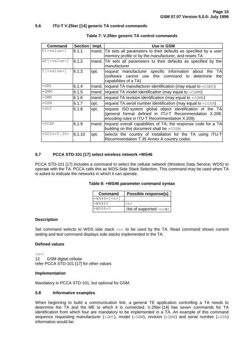
5.6 ITU-T V.25ter [14] generic TA control commands
Table 7: V.25ter generic TA control commands
Command Section Impl. Use in GSMZ[<value>] 6.1.1 mand. TA sets all parameters to their defaults as specified by a user
memory profile or by the manufacturer, and resets TA&F[<value>] 6.1.2 mand. TA sets all parameters to their defaults as specified by the
manufacturerI[<value>] 6.1.3 opt. request manufacturer specific information about the TA
(software cannot use this command to determine thecapabilities of a TA)
+GMI 6.1.4 mand. request TA manufacturer identification (may equal to +CGMI)+GMM 6.1.5 mand. request TA model identification (may equal to +CGMM)+GMR 6.1.6 mand. request TA revision identification (may equal to +CGMR)+GSN 6.1.7 opt. request TA serial number identification (may equal to +CGSN)+GOI 6.1.8 opt. request ISO system global object identification of the TA
(general format defined in ITU-T Recommendation X.208;encoding rules in ITU-T Recommendation X.209)
+GCAP 6.1.9 mand. request overall capabilities of TA; the response code for a TAbuilding on this document shall be +CGSM
+GCI=<T.35> 6.1.10 opt. selects the country of installation for the TA using ITU-TRecommendation T.35 Annex A country codes
5.7 PCCA STD-101 [17] select wireless network +WS46
PCCA STD-101 [17] includes a command to select the cellular network (Wireless Data Service; WDS) tooperate with the TA. PCCA calls this as WDS-Side Stack Selection. This command may be used when TAis asked to indicate the networks in which it can operate.
Table 8: +WS46 parameter command syntax
Command Possible response(s)+WS46=[<n>]+WS46? <n>+WS46=? ( list of supported <n>s)
Description
Set command selects to WDS side stack <n> to be used by the TA. Read command shows currentsetting and test command displays side stacks implemented in the TA.
Defined values
<n>:12 GSM digital cellularrefer PCCA STD-101 [17] for other values
Implementation
Mandatory in PCCA STD-101, but optional for GSM.
5.8 Informative examples
When beginning to build a communication link, a general TE application controlling a TA needs todetermine the TA and the ME to which it is connected. V.25ter [14] has seven commands for TAidentification from which four are mandatory to be implemented in a TA. An example of this commandsequence requesting manufacturer (+GMI), model (+GMM), revision (+GMR) and serial number (+GSN)information would be:
Page 16GSM 07.07 Version 5.0.0: July 1996
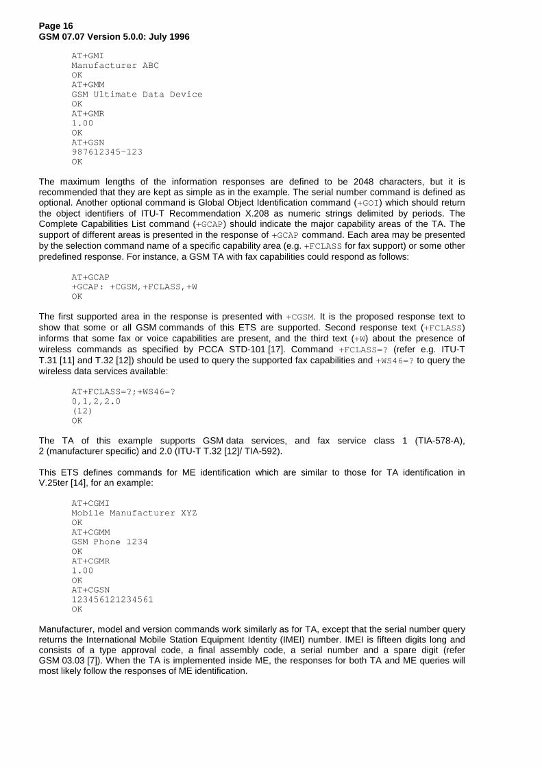
AT+GMIManufacturer ABCOKAT+GMMGSM Ultimate Data DeviceOKAT+GMR1.00OKAT+GSN987612345-123OK
The maximum lengths of the information responses are defined to be 2048 characters, but it isrecommended that they are kept as simple as in the example. The serial number command is defined asoptional. Another optional command is Global Object Identification command (+GOI) which should returnthe object identifiers of ITU-T Recommendation X.208 as numeric strings delimited by periods. TheComplete Capabilities List command (+GCAP) should indicate the major capability areas of the TA. Thesupport of different areas is presented in the response of +GCAP command. Each area may be presentedby the selection command name of a specific capability area (e.g. +FCLASS for fax support) or some otherpredefined response. For instance, a GSM TA with fax capabilities could respond as follows:
AT+GCAP+GCAP: +CGSM,+FCLASS,+WOK
The first supported area in the response is presented with +CGSM. It is the proposed response text toshow that some or all GSM commands of this ETS are supported. Second response text (+FCLASS)informs that some fax or voice capabilities are present, and the third text (+W) about the presence ofwireless commands as specified by PCCA STD-101 [17]. Command +FCLASS=? (refer e.g. ITU-TT.31 [11] and T.32 [12]) should be used to query the supported fax capabilities and +WS46=? to query thewireless data services available:
AT+FCLASS=?;+WS46=?0,1,2,2.0(12)OK
The TA of this example supports GSM data services, and fax service class 1 (TIA-578-A),2 (manufacturer specific) and 2.0 (ITU-T T.32 [12]/ TIA-592).
This ETS defines commands for ME identification which are similar to those for TA identification inV.25ter [14], for an example:
AT+CGMIMobile Manufacturer XYZOKAT+CGMMGSM Phone 1234OKAT+CGMR1.00OKAT+CGSN123456121234561OK
Manufacturer, model and version commands work similarly as for TA, except that the serial number queryreturns the International Mobile Station Equipment Identity (IMEI) number. IMEI is fifteen digits long andconsists of a type approval code, a final assembly code, a serial number and a spare digit (referGSM 03.03 [7]). When the TA is implemented inside ME, the responses for both TA and ME queries willmost likely follow the responses of ME identification.
Page 17GSM 07.07 Version 5.0.0: July 1996
6 Call control commands and methods
This clause describes the control of GSM calls. Normal data and fax call control is done as in ITU-TRecommendations V.25ter [14], T.31 [11] and T.32 [12]. For voice call originating, refer subclause "ITU-TV.25ter dial command D".
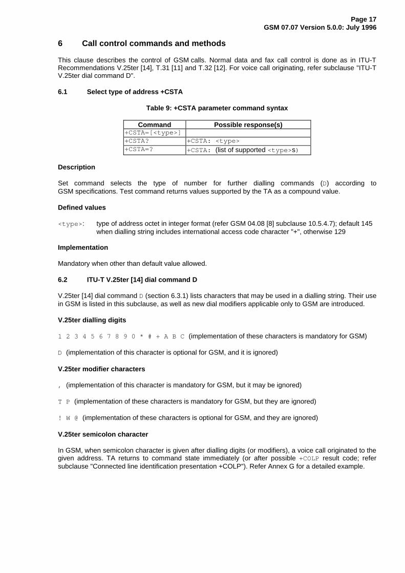
6.1 Select type of address +CSTA
Table 9: +CSTA parameter command syntax
Command Possible response(s)+CSTA=[<type>]+CSTA? +CSTA: <type>+CSTA=? +CSTA: (list of supported <type> s)
Description
Set command selects the type of number for further dialling commands (D) according toGSM specifications. Test command returns values supported by the TA as a compound value.
Defined values
<type> : type of address octet in integer format (refer GSM 04.08 [8] subclause 10.5.4.7); default 145 when dialling string includes international access code character "+", otherwise 129
Implementation
Mandatory when other than default value allowed.
6.2 ITU-T V.25ter [14] dial command D
V.25ter [14] dial command D (section 6.3.1) lists characters that may be used in a dialling string. Their usein GSM is listed in this subclause, as well as new dial modifiers applicable only to GSM are introduced.
V.25ter dialling digits
1 2 3 4 5 6 7 8 9 0 * # + A B C (implementation of these characters is mandatory for GSM)
D (implementation of this character is optional for GSM, and it is ignored)
V.25ter modifier characters
, (implementation of this character is mandatory for GSM, but it may be ignored)
T P (implementation of these characters is mandatory for GSM, but they are ignored)
! W @ (implementation of these characters is optional for GSM, and they are ignored)
V.25ter semicolon character
In GSM, when semicolon character is given after dialling digits (or modifiers), a voice call originated to thegiven address. TA returns to command state immediately (or after possible +COLP result code; refersubclause "Connected line identification presentation +COLP"). Refer Annex G for a detailed example.

Page 18GSM 07.07 Version 5.0.0: July 1996
GSM modifier characters
> (refer subclause "Direct dialling from phonebooks")
I or i (override the CLIR supplementary service subscription default value for this call; refer subclause"Calling line identification restriction +CLIR")
G or g (control the CUG supplementary service information for this call; uses index and info values setwith command +CCUG; refer subclause "Closed user group +CCUG")
6.3 Direct dialling from phonebooks
GSM ME and SIM can contain phonebooks which have a phone number and an alphanumeric field foreach phonebook entry location. The use of V.25ter [14] dialling command ensures that direct dialling fromME and SIM phonebook is possible through ordinary communications software which just gives the phonenumber field to be filled and then use the D command to originate the call. Available memories may bequeried with Select Phonebook Storage test command +CPBS=?, and location range for example withRead Phonebook Entries test command +CPBR=?.
Execute commands
1. D><str>[I][G][;] originate call to phone number which corresponding alphanumeric field is<str> (if possible, all available memories should be searched for the correctentry)
2. D>mem<n>[I][G][;] originate call to phone number in memory mem entry location <n> (availablememories may be queried with Select Phonebook Storage test command+CPBS=?; mem could be e.g. ME or SIM)
3. D><n>[I][G][;] originate call to phone number in entry location <n> (it is manufacturer specificwhich memory storage of ME, SIM and TA is used; command SelectPhonebook Memory Storage +CPBS setting is recommended to be used)
Semicolon character shall be added when voice call is originated. CLIR and CUG per call base modifiersmay also be present.
Responses
Possible error responses include +CME ERROR: <err> when error is related to ME functionality. Refersubclause 9.2 for possible error values. Otherwise TA responses can have values defined by V.25ter [14]and commands Service Reporting Control +CR and Connected Line Identification Presentation +COLP.Detailed error report of an unsuccessful originated call failed in a GSM network error can be obtained withcommand Extended Error Report +CEER (if implemented).
Defined values
<str> : string type value, which should equal to an alphanumeric field in at least one phonebook entry in the searched memories; used character set should be the one selected with SelectTE Character Set +CSCS
<n>: integer type memory location should be in the range of locations available in the memory used
Implementation
Mandatory when direct dialling is implemented. Also phonebook commands implementation is required.

Page 19GSM 07.07 Version 5.0.0: July 1996
6.4 Call mode +CMOD
Table 10: +CMOD parameter command syntax
Command Possible response(s)+CMOD=[<mode>]+CMOD? +CMOD: <mode>+CMOD=? +CMOD: (list of supported <mode>s)
Description
Set command selects the call mode of further dialling commands (D) or for next answering command (A).Mode can be either single or alternating (in this ETS, terms "alternating mode" and "alternating call" referto all GSM bearer and teleservices that incorporate more than one basic service (voice, data, fax) withinone call). When single mode is selected the call originating and hangup procedures are similar toprocedures specified in ITU-T Recommendations V.25ter [14], T.31 [11] and T.32 [12]. In GSM there canbe voice followed by data (refer GSM 02.02 [1]), alternating voice/data (refer GSM 02.02 [1]) andalternating voice/fax calls (refer GSM 02.03 [2]). Refer next two subclauses for alternating call controlmethods.
Test command returns values supported by the TA as a compound value.
NOTE: +CMOD shall be set to zero after a successfully completed alternating mode call. It shallbe set to zero also after a failed answering. The power-up, factory (&F) and user resets(Z) shall also set the value to zero. This reduces the possibility that alternating modecalls are originated or answered accidentally.
Defined values
<mode>:0 single mode1 alternating voice/fax (teleservice 61)2 alternating voice/data (bearer service 61)3 voice followed by data (bearer service 81)also all other values below 128 are reserved by this ETS
Implementation
Mandatory when alternating mode calls are implemented in the TA.
6.5 Hangup call +CHUP
Table 11: +CHUP action command syntax
Command Possible response(s)+CHUP+CHUP=?
Description
Execution command causes the TA to hangup the current GSM call of the ME.
NOTE: The purpose of this command is not to replace the V.25ter [14] command H, but togive an assured procedure to terminate an alternating mode call. Refer nextsubclause.

Page 20GSM 07.07 Version 5.0.0: July 1996
Implementation
Mandatory when alternating mode calls implemented in the TA.
6.6 Alternating mode call control method
This subclause describes the procedure to handle alternating mode calls with AT commands. Proceduresare mandatory when alternating mode calls are implemented in the TA.
Voice followed by data call (bearer service 81)
Figure 4 shows commands to start the call, to switch from voice to data (In-Call Modification) and to hangup the call. +CMOD and +FCLASS commands indicate the current settings before dialling or answeringcommand, not that they shall be given just before D or A command. Refer subclause "Cellular result codes+CRC" for possible +CRING result code values. Refer Annex F for a detailed example.
VOICE DATA
HANGUP
ATH ordrop DTR orAT+CHUP orremote initiated hangup
ATD or ATA orremote initiated
ATDxxx;
AT+CMOD=3AT+FCLASS=0
TA sets +CMOD=0
+CRING: VOICE/XXXAT+CMOD=3;+FCLASS=0
MTMO
ATH ordrop DTR orAT+CHUP orremote initiated hangup
ATA
Figure 4: Voice followed by data call

Page 21GSM 07.07 Version 5.0.0: July 1996
Voice/ data call (bearer service number 61)
Figure 5 shows the commands to start the call, to switch between modes (In-Call Modification) and tohang up the call. +CMOD and +FCLASS commands indicate the current settings before dialling oranswering command, not that they shall be given just before D or A command. Refer subclause "Cellularresult codes +CRC" for possible +CRING result code values. Refer Annex E for a detailed example.
VOICE DATA
HANGUP
AT+CHUP orremote initiated hangup
ATH ordrop DTR orAT+CHUP orremote initiated hangup
ATD or ATA orremote initiated
ATH or drop DTR orremote initiated
ATDxxxATDxxx;
AT+CMOD=2AT+FCLASS=0
TA sets +CMOD=0
+CRING: ALT VOICE/XXXAT+CMOD=2;+FCLASS=0
+CRING: ALT XXX/VOICEAT+CMOD=2;+FCLASS=0
MT voice first MT data firstMO
ATA ATA
Figure 5: Alternating voice and data call
Voice/ fax call (teleservice number 61)
Figure 6 shows the commands to start the call, to switch between modes (In-Call Modification) and tohang up the call. +CMOD and +FCLASS commands indicate the current settings before dialling oranswering command, not that they shall be given just before D or A command. The parameter "x" of+FCLASS command can be 1, 1.0, 2 or 2.0.
NOTE: The transition from fax mode to voice mode is for further study.
VOICE FAX
HANGUP
ATH ordrop DTR orAT+CHUP orremote initiated hangup
ATD orremote initiated
ATDxxxATDxxx;
AT+CMOD=1AT+FCLASS=x
TA sets +CMOD=0
+CRING: ALT VOICE/FAXAT+CMOD=1;+FCLASS=x
+CRING: ALT FAX/VOICEAT+CMOD=1;+FCLASS=x
MT voice first MT fax firstMO
ATA ATA
refer ITU-T T.31 [11] and T.32 [12]for different hangup possibilities(also AT+CHUP shall hangup)
Figure 6: Alternating voice and fax call

Page 22GSM 07.07 Version 5.0.0: July 1996
6.7 Select bearer service type +CBST
Table 12: +CBST parameter command syntax
Command Possible response(s)+CBST=[<speed>[,<name>[,<ce>]]]+CBST? +CBST: <speed>[,<name>,<ce>]+CBST=? +CBST: (list of supported <speed> s), (list of
supported <name>s), (list of supported <ce> s)
Description
Set command selects the bearer service <name> with data rate <speed> , and the connection element<ce> to be used when data calls are originated (refer GSM 02.02 [1]).
Test command returns values supported by the TA as compound values.
Defined values
<speed> :0 autobauding (automatic selection of the speed)1 300 bps (V.21)2 1200 bps (V.22)3 1200/75 bps (V.23)4 2400 bps (V.22bis)5 2400 bps (V.26ter)6 4800 bps (V.32)7 9600 bps (V.32)8 unknown or network specific (no speed specification needed)9 7200 bps (V.32bis)10 12000 bps (V.32bis)11 14400 bps (V.32bis)12 9600 bps (V.34)13 12000 bps (V.34)14 14400 bps (V.34)15 19200 bps (V.34)16 28800 bps (V.34)65 300 bps (V.110)66 1200 bps (V.110)68 2400 bps (V.110)70 4800 bps (V.110)71 9600 bps (V.110)74 12000 bps (V.110)75 14400 bps (V.110)79 19200 bps (V.110)81 38400 bps (V.110)also all other values below 128 are reserved by this ETS
<name>:0 asynchronous modem1 synchronous modem2 PAD Access (asynchronous)3 Packet Access (synchronous)also all other values below 128 are reserved by this ETS
<ce> :0 transparent1 non-transparent
Implementation
Mandatory when data calls implemented.

Page 23GSM 07.07 Version 5.0.0: July 1996
6.8 Radio link protocol +CRLP
Table 13: +CRLP parameter command syntax
Command Possible response(s)+CRLP=[<iws>[,<mws>[,<T1>[,<N2>]]]]+CRLP? +CRLP: <iws>,<mws>,<T1>,<N2>+CRLP=? +CRLP: (list of supported <iws> s), (list of supported
<mws>s), (list of supported <T1>s), (list of supported <N2>s)
Description
Radio link protocol parameters may be altered with set command.
NOTE: If radio link protocol is not used, but some other error correcting protocol, V.25ter [14]Error Control Selection test command +ES=? may be used to indicate the presence ofthe protocol.
Test command returns values supported by the TA as a compound value.
Defined values
<iws> , <mws>, <T1>, <N2>: IWF to MS window size (default 61), MS to IWF window size (default 61),acknowledgement timer T1 (default 48), and retransmission attempts N2 (default 6) in integerformat (refer GSM 04.22 [18] subclause 5.4.3)
Implementation
Mandatory when RLP implemented.
6.9 Service reporting control +CR
Table 14: +CR parameter command syntax
Command Possible response(s)+CR=[<mode>]+CR? +CR: <mode>+CR=? +CR: (list of supported <mode>s)
Description
Set command controls whether or not intermediate result code +CR: <serv> is returned from the TA tothe TE. If enabled, the intermediate result code is transmitted at the point during connect negotiation atwhich the TA has determined which speed and quality of service will be used, before any error control ordata compression reports are transmitted, and before any final result code (e.g. CONNECT) is transmitted.
NOTE: This command replaces V.25ter [14] command Modulation Reporting Control +MR,which is not appropriate for use in the GSM network. Possible error control (other thanradio link protocol) and data compression reporting can be enabled with V.25tercommands Error Control Reporting +ER and Data Compression Reporting +DR.
Test command returns values supported by the TA as a compound value.
Page 24GSM 07.07 Version 5.0.0: July 1996
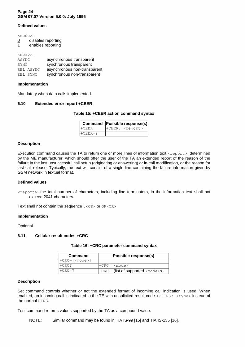
Defined values
<mode>:0 disables reporting1 enables reporting
<serv> :ASYNC asynchronous transparentSYNC synchronous transparentREL ASYNC asynchronous non-transparentREL SYNC synchronous non-transparent
Implementation
Mandatory when data calls implemented.
6.10 Extended error report +CEER
Table 15: +CEER action command syntax
Command Possible response(s)+CEER +CEER: <report>+CEER=?
Description
Execution command causes the TA to return one or more lines of information text <report> , determinedby the ME manufacturer, which should offer the user of the TA an extended report of the reason of thefailure in the last unsuccessful call setup (originating or answering) or in-call modification, or the reason forlast call release. Typically, the text will consist of a single line containing the failure information given byGSM network in textual format.
Defined values
<report> : the total number of characters, including line terminators, in the information text shall notexceed 2041 characters.
Text shall not contain the sequence 0<CR> or OK<CR>
Implementation
Optional.
6.11 Cellular result codes +CRC
Table 16: +CRC parameter command syntax
Command Possible response(s)+CRC=[<mode>]+CRC? +CRC: <mode>+CRC=? +CRC: (list of supported <mode>s)
Description
Set command controls whether or not the extended format of incoming call indication is used. Whenenabled, an incoming call is indicated to the TE with unsolicited result code +CRING: <type> instead ofthe normal RING.
Test command returns values supported by the TA as a compound value.
NOTE: Similar command may be found in TIA IS-99 [15] and TIA IS-135 [16].

Page 25GSM 07.07 Version 5.0.0: July 1996
Defined values
<mode>:0 disables extended format1 enables extended format
<type> :ASYNC asynchronous transparentSYNC synchronous transparentREL ASYNC asynchronous non-transparentREL SYNC synchronous non-transparentFAX facsimile (TS 62)VOICE normal voice (TS 11)VOICE/ XXX voice followed by data (BS 81) (XXX is ASYNC, SYNC, REL ASYNC or REL SYNC)ALT VOICE/ XXX alternating voice/data, voice first (BS 61)ALT XXX/VOICE alternating voice/data, data first (BS 61)ALT VOICE/FAX alternating voice/fax, voice first (TS 61)ALT FAX/VOICE alternating voice/fax, fax first (TS 61)
Implementation
Mandatory when data or fax calls implemented.
6.12 ITU-T V.25ter [14] call control commands
Table 17: V.25ter call control commands
Command Section Impl. Use in GSMD[<dial_string>][;]
6.3.1 mand. originates a call
T 6.3.2 mand. ignored (select tone dialling)P 6.3.3 mand. ignored (select pulse dialling)A 6.3.5 mand. answer a callH[<value>] 6.3.6 mand. hang-up a single mode call; for alternate mode call refer
subclause "Hangup call +CHUP" (only value equal to zeroneeded)
O[<value>] 6.3.7 mand. returns TA to online data state from online command mode (onlyvalue equal to zero needed)
S0=[<value>] 6.3.8 mand. sets the number of call indications (rings) before automaticallyanswering the call; value equalling zero disables automaticanswering and is the default
S6=[<value>] 6.3.9 mand. ignored (pause before blind dialling)S7=[<value>] 6.3.10 mand. sets number of seconds to wait for completion of call answering or
originating procedure before giving up and disconnectingS8=[<value>] 6.3.11 mand. sets number of seconds to wait when comma dial modifier
encountered in dial string of D command (default is 2 seconds)S10=[<value>] 6.3.12 mand. sets number of tenths of seconds to wait before disconnecting
after TA has indicated the absence of received line signalL[<value>] 6.3.13 mand. ignored (monitor speaker loudness)M[<value>] 6.3.14 mand. ignored (monitor speaker mode)

Page 26GSM 07.07 Version 5.0.0: July 1996
6.13 ITU-T V.25ter [14] data compression commands
Table 18: V.25ter data compression commands
Command Section Impl. Use in GSM+DS=[<dir>[,<neg>[,<P1>[,<P2>]]]]
6.6.1 mand.whenV.42bis
controls ITU-T Recommendation V.42bis datacompression functions; for subparameter defaults inGSM refer GSM 04.22 [18]
+DR=[<value>] 6.6.2 mand.whenV.42bis
determines whether the use of V.42bis is informed usingintermediate result code +DR: <type> before goingonline data state after call answering or originating
6.14 Informative examples
Two major areas covered in this subclause are the alternating mode call handling (voice and fax, or voiceand data) and the data call setup. The definition of the commands is made such that the dialling commandof V.25ter [14] (D) still always originates a call. The purpose is to support all current TE applications usingthe dialling command as default. Fax calls are controlled following the rules of ITU-T T.31 [11] andT.32 [12] standards.
An example where a voice call is originated:
ATD+1 812 555673I; (type of address defaults to 145, CLIR subscription is overridden for this call)OK (call setup was successful)
An example where a voice call is attempted from a phonebook:
ATD="Doe Joe"G; (enable CUG control for this call)+CME ERROR: 22 (entry "Doe Joe" is not found)
Also supplementary services can be controlled using dial command according to GSM 02.30 [19]. Anexample of Call Forwarding on no reply for telephony with the adjustment of the no reply condition timeron 25 seconds:
ATD**61*+1812555673*11*25#OK (modification was successful)
Two new commands are created for controlling the alternating mode calls. First one, Call Mode (+CMOD),selects between single and alternating mode. Because this is a crucial command, it is defined that thevalue is set back to zero (single mode) after every successfully originated alternating mode call. Also onpower-up and factory or user resets, the value is set to zero. The second new command, Hangup Call(+CHUP), is not a replacement of V.25ter [14] command H, but a command which reliably disconnects thecall in GSM network. This is defined because the H command is used to switch from fax or data mode tovoice mode.
The setting of GSM bearer service (data circuit duplex asynchronous and synchronous, PAD accesscircuit asynchronous, or data packet duplex synchronous), is done with Select Bearer Service Type(+CBST). It chooses one of the four mentioned bearer services, the data rate of the service (or actually themodulation when modem IWFs are used), and enables or disables RLP. Command Radio Link Protocol(+CRLP) is used to set the RLP parameters in the radio path.

Page 27GSM 07.07 Version 5.0.0: July 1996
Service Reporting Control command (+CR) is defined similarly as the reporting of modulation, V.18, errorcontrol, and data compression which are V.25ter [14] features used to show information about the type ofthe established connection before the CONNECT intermediate result code. +CR command has onesubparameter which specifies whether the intermediate result code +CR: <serv> is returned or not. Theresult code should be returned before any V.25ter [14] reporting result codes. An example of setting up anasynchronous 9600 bit/s modem connection with service reporting:
AT+CBST=7,0,1 (asynchronous modem 9600 bit/s and RLP)OKAT+CR=1 (enable reporting)OKATD1234567890+CR: REL ASYNCCONNECT 9600
As GSM network offers more information about the reason of the failure in call originating and answeringthan normal PSTN, it is useful to add an extra command to return this information to the TE. Thisinformation should not be returned always after unsuccessful call originating or answering, because manyTE applications look for just the regular NO CARRIER, BUSY, NO ANSWER and CONNECT messages.Action command Extended Error Report (+CEER) does not have any subparameters, and it returns thecause of the latest call setup failure. This information may be the textual presentation of the GSM networkfailure code (refer GSM specification 04.08 [8] Annex H), or some other information defined by the TAmanufacturer.
7 Network service related commands
This clause describes GSM network related commands, which are not covered in call control clause ofthis ETS. Commands include GSM supplementary service handling, MSISDN query, ME and networkfacility locking, and network registration information query.
7.1 Subscriber number +CNUM
Table 19: +CNUM action command syntax
Command Possible response(s)+CNUM +CNUM: [<alpha1>],<number1>,<type1>[,<speed>,<service>[,<itc>]]
[<CR><LF>+CNUM: [<alpha2>],<number2>,<type2>[,<speed>,<service> [,<itc>]][...]]+CME ERROR: <err>
+CNUM=?
Description
Action command returns the MSISDNs related to the subscriber (this information can be stored in the SIMor in the ME). If subscriber has different MSISDN for different services, each MSISDN is returned in aseparate line. Refer subclause 9.2 for possible <err> values.

Page 28GSM 07.07 Version 5.0.0: July 1996
Defined values
<alpha x>: optional alphanumeric string associated with <number x>; used character set should be theone selected with command Select TE Character Set +CSCS
<number x>: string type phone number of format specified by <type x>
<type x>: type of address octet in integer format (refer GSM 04.08 [8] subclause 10.5.4.7)
<speed> : as defined in subclause 6.7
<service> (service related to the phone number):0 asynchronous modem1 synchronous modem2 PAD Access (asynchronous)3 Packet Access (synchronous)4 voice5 faxalso all other values below 128 are reserved by this ETS
<itc> (information transfer capability):0 3.1 kHz1 UDI
Implementation
Optional.
7.2 Network registration +CREG
Table 20: +CREG parameter command syntax
Command Possible response(s)+CREG=[<n>]+CREG? +CREG: <n>,<stat>[,<lac>,<ci>]
+CME ERROR: <err>+CREG=? +CREG: ( list of supported <n>s)
Description
Set command controls the presentation of an unsolicited result code +CREG: <stat> when <n>=1 andthere is a change in the ME network registration status, or code +CREG: <stat>[,<lac>,<ci>] when<n>=2 and there is a change of the network cell.
Read command returns the status of result code presentation and an integer <stat> which showswhether the network has currently indicated the registration of the ME. Location information elements<lac> and <ci> are returned only when <n>=2 and ME is registered in the network. Refer subclause 9.2for possible <err> values.
Defined values
<n>:0 disable network registration unsolicited result code1 enable network registration unsolicited result code +CREG: <stat>2 enable network registration and location information unsolicited result code +CREG:
<stat>[,<lac>,<ci>]
<stat> :0 not registered, ME is not currently searching a new operator to register to1 registered, home network2 not registered, but ME is currently searching a new operator to register to

Page 29GSM 07.07 Version 5.0.0: July 1996
3 registration denied4 unknown5 registered, roaming
<lac> : string type; two byte location area code in hexadecimal format (e.g. "00C3" equals 193 in decimal)
<ci> : string type; two byte cell ID in hexadecimal format
Implementation
Optional.
7.3 Operator selection +COPS
Table 21: +COPS parameter command syntax
Command Possible response(s)+COPS=[<mode>[,<format>[,<oper>]]] +CME ERROR: <err>+COPS? +COPS: <mode>[,<format>,<oper>]
+CME ERROR: <err>+COPS=? +COPS: list of supported (<stat>, long alphanumeric
<oper>, short alphanumeric <oper>, numeric <oper>) s+CME ERROR: <err>
Description
Set command forces an attempt to select and register the GSM network operator. <mode> is used toselect whether the selection is done automatically by the ME or is forced by this command to operator<oper> (it shall be given in format <format> ). If the selected operator is not available, no other operatorshall be selected (except <mode>=4). The selected operator name format shall apply to further readcommands (+COPS?) also. <mode>=2 forces an attempt to deregister from the network. The selectedmode affects to all further network registration (e.g. after <mode>=2, ME shall be unregistered until<mode>=0 or 1 is selected). Refer subclause 9.2 for possible <err> values. This command should beabortable when registration/deregistration attempt is made.
Read command returns the current mode and the currently selected operator. If no operator is selected,<format> and <oper> are omitted.
Test command returns a list of quadruplets, each representing an operator present in the network.Quadruplet consists of an integer indicating the availability of the operator <stat> , long and shortalphanumeric format of the name of the operator, and numeric format representation of the operator. Anyof the formats may be unavailable and should then be an empty field. The list of operators shall be inorder: home network, networks referenced in SIM, and other networks.
Defined values
<mode>:0 automatic (<oper> field is ignored)1 manual (<oper> field shall be present)2 deregister from network3 set only <format> (for read command +COPS?), do not attempt registration/deregistration
(<oper> field is ignored); this value is not applicable in read command response4 manual/automatic (<oper> field shall be present); if manual selection fails, automatic mode
(<mode>=0) is entered
<format> :0 long format alphanumeric <oper>1 short format alphanumeric <oper>2 numeric <oper>

Page 30GSM 07.07 Version 5.0.0: July 1996
<oper> : string type; <format> indicates if the format is alphanumeric or numeric; long alphanumericformat can be up to 16 characters long and short format up to 8 characters (refer GSM MoUSE.13 [9]); numeric format is the GSM Location Area Identification number (refer GSM 04.08 [8]subclause 10.5.1.3) which consists of a three BCD digit country code coded as in ITU-T E.212Annex A [10], plus a two BCD digit network code, which is administration specific; returned <oper>shall not be in BCD format, but in IRA characters converted from BCD; hence the number hasstructure: (country code digit 3)(country code digit 2)(country code digit 1)(network code digit2)(network code digit 1)
<stat> :0 unknown1 available2 current3 forbidden
Implementation
Optional.
7.4 Facility lock +CLCK
Table 22: +CLCK action command syntax
Command Possible response(s)+CLCK=<fac>,<mode>[,<passwd>[,<class>]]
+CME ERROR: <err>when <mode>=2 and command successful:+CLCK: <status>[,<class1>[<CR><LF>+CLCK: <status>,<class2>[...]]
+CLCK=? +CLCK: (list of supported <fac> s)+CME ERROR: <err>
Description
Execute command is used to lock, unlock or interrogate a ME or a network facility <fac> . Password isnormally needed to do such actions. Refer subclause 9.2 for possible <err> values. This commandshould be abortable when network facilities are set or interrogated.
Call barring facilities are based on GSM supplementary services (refer GSM 02.88 [6]). The interaction ofthese with other commands based on other GSM supplementary services is described in theGSM standard.
Test command returns facility values supported by the TA as a compound value.
Defined values
<fac> values reserved by this ETS:"CS" CNTRL (lock CoNTRoL surface (e.g. phone keyboard))"PS" PH-SIM (lock PHone to SIM card) (ME asks password when other than current SIM card
inserted)"SC" SIM (lock SIM card) (SIM asks password in ME power-up and when this lock command issued)"AO" BAOC (Barr All Outgoing Calls) (refer GSM 02.88 [6] clause 1)"OI" BOIC (Barr Outgoing International Calls) (refer GSM 02.88 [6] clause 1)"OX" BOIC-exHC (Barr Outgoing International Calls except to Home Country) (refer GSM 02.88 [6]
clause 1)"AI" BAIC (Barr All Incoming Calls) (refer GSM 02.88 [6] clause 2)"IR" BIC-Roam (Barr Incoming Calls when Roaming outside the home country) (refer GSM 02.88 [6]
clause 2)"NT" barr incoming calls from numbers Not stored to TA memory"NM" barr incoming calls from numbers Not stored to ME memory"NS" barr incoming calls from numbers Not stored to SIM memory

Page 31GSM 07.07 Version 5.0.0: July 1996
"NA" barr incoming calls from numbers Not stored in Any memory"AB" All Barring services (refer GSM 02.30 [19])"AG" All outGoing barring services (refer GSM 02.30 [19])"AC" All inComing barring services (refer GSM 02.30 [19])"FD" SIM fixed dialling memory feature (if PIN2 authentication has not been done during the current
session, PIN2 is required as <passwd> )
<mode>:0 unlock1 lock2 query status
<status> :0 not active1 active
<passwd> : string type; shall be the same as password specified for the facility from the ME user interfaceor with command Change Password +CPWD
<class x> is a sum of integers each representing a class of information (default 7 equals to all classes):1 voice2 data4 faxalso all other values below 128 are reserved by this ETS
Implementation
Optional.
7.5 Change password +CPWD
Table 23: +CPWD action command syntax
Command Possible response(s)+CPWD=<fac>,<oldpwd>,<newpwd> +CME ERROR: <err>+CPWD=? +CPWD: list of supported (<fac>,<pwdlength>) s
+CME ERROR: <err>
Description
Action command sets a new password for the facility lock function defined by command Facility Lock+CLCK. Refer subclause 9.2 for possible <err> values.
Test command returns a list of pairs which present the available facilities and the maximum length of theirpassword.
Defined values
<fac> :"P2" SIM PIN2 refer Facility Lock +CLCK for other values
<oldpwd> , <newpwd>: string type; <oldpwd> shall be the same as password specified for the facilityfrom the ME user interface or with command Change Password +CPWD and <newpwd> is the newpassword; maximum length of password can be determined with <pwdlength>
<pwdlength> : integer type maximum length of the password for the facility
Implementation
Optional.

Page 32GSM 07.07 Version 5.0.0: July 1996
7.6 Calling line identification presentation +CLIP
Table 24: +CLIP parameter command syntax
Command Possible response(s)+CLIP=[<n>]+CLIP? +CLIP: <n>,<m>+CLIP=? +CLIP: (list of supported <n>s)
Description
This command refers to the GSM supplementary service CLIP (Calling Line Identification Presentation)that enables a called subscriber to get the calling line identity (CLI) of the calling party when receiving amobile terminated call. Set command enables or disables the presentation of the CLI at the TE. It has noeffect on the execution of the supplementary service CLIP in the network.
When the presentation of the CLI at the TE is enabled (and calling subscriber allows), +CLIP:<number>,<type>[,<subaddr>,<satype>[,<alpha>]] response is returned after every RING (or+CRING: <type> ; refer subclause "Cellular result codes +CRC") result code sent from TA to TE. It ismanufacturer specific if this response is used when normal voice call is answered.
Read command gives the status of <n>, and also triggers an interrogation of the provision status of theCLIP service according GSM 02.81 [3] (given in <m>).Test command returns values supported by the TAas a compound value.
Defined values
<n> (parameter sets/shows the result code presentation status in the TA):0 disable1 enable
<m> (parameter shows the subscriber CLIP service status in the network):0 CLIP not provisioned1 CLIP provisioned2 unknown (e.g. no network, etc.)
<number> : string type phone number of format specified by <type>
<type> : type of address octet in integer format (refer GSM 04.08 [8] subclause 10.5.4.7)
<subaddr> : string type subaddress of format specified by <satype>
<satype> : type of subaddress octet in integer format (refer GSM 04.08 [8] subclause 10.5.4.8)
<alpha> : optional string type alphanumeric representation of <number> corresponding to the entry foundin phonebook; used character set should be the one selected with command Select TE CharacterSet +CSCS
Implementation
Optional.
7.7 Calling line identification restriction +CLIR
Table 25: +CLIR parameter command syntax
Command Possible response(s)+CLIR=[<n>]+CLIR? +CLIR: <n>,<m>+CLIR=? +CLIR: (list of supported <n>s)

Page 33GSM 07.07 Version 5.0.0: July 1996
Description
This command refers to CLIR-service according to GSM 02.81 [3] that allows a calling subscriber toenable or disable the presentation of the CLI to the called party when originating a call.
Set command overrides the CLIR subscription (default is restricted or allowed) when temporary mode isprovisioned as a default adjustment for all following outgoing calls. This adjustment can be revoked byusing the opposite command.. If this command is used by a subscriber without provision of CLIR inpermanent mode the network will act according GSM 02.81 [3].
Read command gives the default adjustment for all outgoing calls (given in <n>), and also triggers aninterrogation of the provision status of the CLIR service (given in <m>). Test command returns valuessupported by the TA as a compound value.
NOTE: On a per call base CLIR functionality is explained in subclause "ITU-T V.25ter [14] dialcommand".
Defined values
<n> (parameter sets the adjustment for outgoing calls):0 presentation indicator is used according to the subscription of the CLIR service1 CLIR invocation2 CLIR suppression
<m> (parameter shows the subscriber CLIR service status in the network):0 CLIR not provisioned1 CLIR provisioned in permanent mode2 unknown (e.g. no network, etc.)3 CLIR temporary mode presentation restricted4 CLIR temporary mode presentation allowed
Implementation
Optional.
7.8 Connected line identification presentation +COLP
Table 26: +COLP parameter command syntax
Command Possible response(s)+COLP=[<n>]+COLP? +COLP: <n>,<m>+COLP=? +COLP: (list of supported <n>s)
Description
This command refers to the GSM supplementary service COLP (Connected Line IdentificationPresentation) that enables a calling subscriber to get the connected line identity (COL) of the called partyafter setting up a mobile originated call. The command enables or disables the presentation of the COL atthe TE. It has no effect on the execution of the supplementary service COLR in the network.
When enabled (and called subscriber allows), +COLP:<number>,<type>[,<subaddr>,<satype> [,<alpha>]] intermediate result code is returned fromTA to TE before any +CR or V.25ter [14] responses. It is manufacturer specific if this response is usedwhen normal voice call is established.
Read command gives the status of <n>, and also triggers an interrogation of the provision status of theCOLP service according GSM 02.81 [3] (given in <m>).
Test command returns values supported by the TA as a compound value.

Page 34GSM 07.07 Version 5.0.0: July 1996
Defined values
<n> (parameter sets/shows the result code presentation status in the TA):0 disable1 enable
<m> (parameter shows the subscriber COLP service status in the network):0 COLP not provisioned1 COLP provisioned2 unknown (e.g. no network, etc.)
<number> , <type> , <subaddr> , <satype> , <alpha> : refer +CLIP
Implementation
Optional.
7.9 Closed user group +CCUG
Table 27: +CCUG parameter command syntax
Command Possible response(s)+CCUG=[<n>[,<index>[,<info>]]]+CCUG? +CCUG: <n>,<index>,<info>+CCUG=?
Description
This command allows control of the Closed User Group supplementary service (refer GSM 02.85 [21]).Set command enables the served subscriber to select a CUG index, to suppress the Outgoing Access(OA), and to suppress the preferential CUG.
Set command with <n>=1 enables to control the CUG information on the air interface as a defaultadjustment for all following outgoing calls. The interaction of this command with other commands basedon other GSM supplementary services is described in the GSM standard.
NOTE: On a per call base CUG functionality is explained in subclause "ITU-T V.25ter [14] dialcommand".
Defined values
<n>:0 disable CUG temporary mode1 enable CUG temporary mode
<index> :0...9 CUG index10 no index (preferred CUG taken from subscriber data)
<info> :0 no information1 suppress OA2 suppress preferential CUG3 suppress OA and preferential CUG
Implementation
Optional.

Page 35GSM 07.07 Version 5.0.0: July 1996
7.10 Call forwarding number and conditions +CCFC
Table 28: +CCFC action command syntax
Command Possible response(s)+CCFC=<reason>,<mode>[,<number>[,<type>[,<class>[,<subaddr>[,<satype>[,<time>]]]]]]
+CME ERROR: <err>when <mode>=2 and command successful:+CCFC: <status>,<class1>[,<number>,<type>[,<subaddr>,<satype>[,<time>]]][<CR><LF>+CCFC: <status>,<class2>[,<number>,<type>[,<subaddr>,<satype>[,<time>]]][...]]
+CCFC=? +CCFC: (list of supported <reason> s)
Description
This command allows control of the call forwarding supplementary service according to GSM 02.82 [4].Registration, erasure, activation, deactivation, and status query are supported.
Test command returns reason values supported by the TA as a compound value.
Defined values
<reason> :0 unconditional1 mobile busy2 no reply3 not reachable4 all call forwarding (refer GSM 02.30 [19])5 all conditional call forwarding (refer GSM 02.30 [19])
<mode>:0 disable1 enable2 query status3 registration4 erasure
<number> : string type phone number of forwarding address in format specified by <type>
<type> : type of address octet in integer format (refer GSM 04.08 [8] subclause 10.5.4.7); default 145 when dialling string includes international access code character "+", otherwise 129
<subaddr> :string type subaddress of format specified by <satype>
<satype> : type of subaddress octet in integer format (refer GSM 04.08 [8] subclause 10.5.4.8); default 128
<class x> is a sum of integers each representing a class of information (default 7 equals to all classes):1 voice2 data4 faxalso all other values below 128 are reserved by this ETS
<time> :1...30 when "no reply" is enabled or queried, this gives the time in seconds to wait before call is forwarded,
default value 20
<status> :0 not active1 active

Page 36GSM 07.07 Version 5.0.0: July 1996
Implementation
Optional.
7.11 Call waiting +CCWA
Table 29: +CCWA parameter command syntax
Command Possible response(s)+CCWA=[<n>[,<mode>[,<class>]]] +CME ERROR: <err>
when <mode>=2 and command successful+CCWA: <status>,<class1>[<CR><LF>+CCWA: <status>,<class2>[...]]
+CCWA? +CCWA: <n>+CCWA=? +CCWA: (list of supported <n>s)
Description
This command allows control of the Call Waiting supplementary service according to GSM 02.83 [5].Activation, deactivation and status query are supported. Parameter <n> is used to disable/enable thepresentation of an unsolicited result code +CCWA: <number>,<type>,<class>[,<alpha>] to the TEwhen call waiting service is enabled. Command should be abortable when network is interrogated.
The interaction of this command with other commands based on other GSM supplementary services isdescribed in the GSM standard.
Test command returns values supported by the TA as a compound value.
Defined values
<n> (sets/shows the result code presentation status in the TA):0 disable1 enable
<mode> (when <mode> parameter is not given, network is not interrogated):0 disable1 enable2 query status
<class x> is a sum of integers each representing a class of information (default 7 equals to all classes):1 voice2 data4 faxalso all other values below 128 are reserved by this ETS
<status> :0 not active1 active
<number> : string type phone number of calling address in format specified by <type>
<type> : type of address octet in integer format (refer GSM 04.08 [8] subclause 10.5.4.7)
<alpha> : optional string type alphanumeric representation of <number> corresponding to the entry foundin phonebook; used character set should be the one selected with command Select TE CharacterSet +CSCS
Implementation
Optional.

Page 37GSM 07.07 Version 5.0.0: July 1996
7.12 Call hold and multiparty +CHLD
Table 30: +CHLD parameter command syntax
Command Possible response(s)+CHLD=[<n>] +CME ERROR: <err>+CHLD=?
Description
This refers to a service that allows a call to be temporarily disconnected from the ME but the connection tobe retained by the network, and to a service that allows multiparty conversation. Calls can be put on hold,recovered, released, and added to conversation similarly as defined in GSM 02.30 [19].. Refer subclause9.2 for possible <err> values.
This is based on the GSM supplementary services HOLD (Call Hold) (refer GSM 02.83 [5] clause 2) andMPTY (MultiParty; refer GSM 02.84 [22]). The interaction of this command with other commands basedon other GSM supplementary services is described in the GSM standard.
NOTE: Call Hold and MultiParty are only applicable to teleservice 11.
Defined values
<n>: integer type; equals to numbers entered before SEND button in GSM 02.30 [19] subclause 4.5.5.1
NOTE: The "directory number" case shall be handled with dial command D, and the END casewith hangup command H (or +CHUP).
Implementation
Optional.
7.13 Call transfer +CTFR
Table 31: +CTFR action command syntax
Command Possible response(s)+CTFR=<number>[,<type>] +CME ERROR: <err>+CTFR=?
Description
This refers to a service that causes the present or incoming call to be forwarded to a specified number.Action command does this. Refer subclause 9.2 for possible <err> values.
NOTE: Call Transfer is only applicable to teleservice 11.
Defined values
<number> : string type phone number of format specified by <type>
<type> : type of address octet in integer format (refer GSM 04.08 [8] subclause 10.5.4.7); default 145 when dialling string includes international access code character "+", otherwise 129
Implementation
Optional.

Page 38GSM 07.07 Version 5.0.0: July 1996
7.14 Unstructured supplementary service data +CUSD
Table 32: +CUSD parameter command syntax
Command Possible response(s)+CUSD=[<n>[,<str>[,<dcs>]]] +CUSD: <m>[,<str>,<dcs>]
+CME ERROR: <err>+CUSD? +CUSD: <n>+CUSD=? +CUSD: (list of supported <n>s)
Description
This command allows control of the Unstuctured Supplementary Service Data (USSD) according toGSM 02.90 [23]. Both network and mobile initiated operations are supported. Parameter <n> is used todisable/enable the presentation of an unsolicited result code (network initiated operation) +CUSD:<m>,<str>,<dcs> to the TE.
When <str> is given, a mobile initiated USSD-string or a response USSD-string to a network initiatedoperation is sent to the network. In case of successful mobile initiated operation, the responseUSSD-string from the network is returned before final result code. The set command should be abortablewhen network is interrogated.
The interaction of this command with other commands based on other GSM supplementary services isdescribed in the GSM standard.
Test command returns values supported by the TA as a compound value.
Defined values
<n> (sets/shows the result code presentation status in the TA):0 disable1 enable
<str> : string type USSD-string (when <str> parameter is not given, network is not interrogated):- if <dcs> indicates that GSM 03.38 [25] default alphabet is used:
- if TE character set other than "HEX" (refer command Select TE Character Set+CSCS): ME/TA converts GSM alphabet into current TE character set accordingto rules of GSM 07.05 [24] Annex A
- if TE character set is "HEX" : ME/TA converts each 7-bit character ofGSM alphabet into two IRA character long hexadecimal number (e.g. characterΠ (GSM 23) is presented as 17 (IRA 49 and 55))
- if <dcs> indicates that 8-bit data coding scheme is used: ME/TA converts each 8-bitoctet into two IRA character long hexadecimal number (e.g. octet with integer value 42is presented to TE as two characters 2A (IRA 50 and 65))
<dcs> : GSM 03.38 [25] Cell Broadcast Data Coding Scheme in integer format (default 0)
<m>:0 no further user action required (network initiated USSD-Notify, or no further information needed
after mobile initiated operation)1 further user action required (network initiated USSD-Request, or further information needed after
mobile initiated operation)
Implementation
Optional.

Page 39GSM 07.07 Version 5.0.0: July 1996
7.15 Advice of Charge +CAOC
Table 33: +CAOC action command syntax
Command Possible response(s)+CAOC +CAOC: <ccm>
+CME ERROR: <err>+CAOC=?
Description
This refers to Advice of Charge supplementary service (GSM 02.24 [26] and GSM 02.86 [27]) that enablessubscriber to get information about the cost of calls. The execute command returns the current call metervalue from the ME. Refer subclause 9.2 for possible <err> values.
NOTE: Advice of Charge values stored in the SIM (ACM, ACMmax, PUCT) can be accessedwith generic SIM access command +CSIM.
Defined values
<ccm>: string type; three bytes of the current call meter value in hexadecimal format (e.g. "00001E" indicates decimal value 30); value is in home units and bytes are similarly coded as ACMmaxvalue in the SIM
Implementation
Optional.
7.16 Supplementary service notifications +CSSN
Table 34: +CSSN parameter command syntax
Command Possible response(s)+CSSN=[<n>[,<m>]]+CSSN? +CSSN: <n>,<m>+CSSN=? +CSSN: (list of supported <n>s), (list of supported <m>s)
Description
This command refers to supplementary service related network initiated notifications. The set commandenables/disables the presentation of notification result codes from TA to TE.
When <n>=1 and a supplementary service notification is received after a mobile originated call setup,intermediate result code +CSSI: <code1>[,<index>] is sent to TE before any other MO call setupresult codes presented in this ETS or in V.25ter [14]. When several different <code1> s are received fromthe network, each of them shall have its own +CSSI result code.
When <m>=1 and a supplementary service notification is received during a mobile terminated call setup orduring a call, or when a forward check supplementary service notification is received, unsolicited resultcode +CSSU: <code2>[,<index>] is sent to TE. In case of MT call setup, result code is sent afterevery +CLIP result code (refer command "Calling line identification presentation +CLIP") and whenseveral different <code2> s are received from the network, each of them shall have its own +CSSU resultcode.
Test command returns values supported by the TA as a compound value.

Page 40GSM 07.07 Version 5.0.0: July 1996
Defined values
<n> (parameter sets/shows the +CSSI result code presentation status in the TA):0 disable1 enable
<m> (parameter sets/shows the +CSSU result code presentation status in the TA):0 disable1 enable
<code1> (it is manufacturer specific, which of these codes are supported):0 unconditional call forwarding is active1 some of the conditional call forwardings are active2 call has been forwarded3 call is waiting4 this is a CUG call (also <index> present)5 outgoing calls are barred6 incoming calls are barred7 CLIR suppression rejected
<index> : refer "Closed user group +CCUG"
<code2> (it is manufacturer specific, which of these codes are supported):0 this is a forwarded call (MT call setup)1 this is a CUG call (also <index> present) (MT call setup)2 call has been put on hold (during a voice call)3 call has been retrieved (during a voice call)4 multiparty call entered (during a voice call)5 call on hold has been released (this is not a SS notification) (during a voice call)6 forward check SS message received (can be received whenever)
Implementation
Optional.
7.17 Informative examples
This subclause includes all the GSM supplementary service related commands, additional commands tolock ME and SIM capabilities, and commands to check the network registration status.
An example where MSISDNs of a ME are queried, calls are forwarded to different numbers when mobileis busy (CFB) or when it does not answer (CFNRy). The status of CFNRy is read:
AT+CNUM+CNUM: ,"+358501234567",145,,4 (voice number)OKAT+CCFC=1,1,"931123456" (enable CFB)OKAT+CCFC=2,1,"921654321" (enable CFNRy)OKAT+CCFC=1,2 (query CFNRy)+CCFC: 1,7,"+35821654321",145,,,20 (forward after 20 seconds)OK

Page 41GSM 07.07 Version 5.0.0: July 1996
An example of Call Waiting (+CCWA), Call Hold and Multiparty (+CHLD), and Connected Line IdentificationPresentation (+COLP) usage:
AT+CCWA=1,1;+COLP=1 (enable call waiting and COLP result codes)OKATD9311234567; (originate a voice call)+COLP: "+358311234567",145OK...conversation...+CCWA: "+358317654321",145 (another call is waiting)AT+CHLD=2 (put first call on hold and answer the second one)OK...conversation...AT+CHLD=1 (release the second (active) call and recover the first (held) call)OKATH (release the first call)OK
Call barring supplementary services are combined in one command, Facility Lock (+CLCK), which is alsoused to restrict ME and SIM functionality Some of the facilities require a password when enabled ordisabled. An additional command, Change Password (+CPWD), is defined for changing the password ofdifferent barring and restriction facilities. An example where locking status of outgoing international calls isinterrogated and then barred, and the password of the SIM card lock (Personal Identity Number, PIN) ischanged:
AT+CLCK="OI",2+CLCK: 0,7OKAT+CLCK="OI",1,"1234"OKAT+CPWD="SC","4321","1234"OK
Operator Selection (+COPS) command is used for querying the status of all GSM operators detected in thearea, and switching between operators.
Following example illustrates the current operator situation in Finland. Two operators networks are found,the status of Tele is unknown and Radiolinja is currently selected. Read command shows that automaticselection mode is on and that Radiolinja is selected. Then an attempt is made to access Tele, but it isdenied (shown by +CME ERROR).
AT+COPS=?+COPS: (2,"RADIOLINJA","RL","24405"),(0,"TELE","TELE","24491")OKAT+COPS?+COPS: 0,0,"RADIOLINJA"OKAT+COPS=1,0,"TELE"+CME ERROR: 3

Page 42GSM 07.07 Version 5.0.0: July 1996
When a terminal wanders between countries (i.e. networks), an application may follow this e.g. with thefollowing scenario:
AT+CREG=1 (enable +CREG: <stat> unsolicited result code)OKAT+CREG?+CREG: 1,1 (ME is registered in home PLMN)OKAT+COPS=3,2;+COPS?;+COPS=3,0;+COPS?+COPS: 0,2,"24405" (get the country...+COPS: 0,0,"RADIOLINJA" ...and operator name)OK...user wanders to another PLMN...+CREG: 2 (deregistered, roaming ongoing)+CREG: 5 (registered again, not home PLMN)AT+COPS=3,2;+COPS?;+COPS=3,0;+COPS?+COPS: 0,2,"24001" (get the country...+COPS: 0,0,"TELIA MOBITEL" ...and operator name)OK...user loses connection, no other PLMNs around...+CREG: 0
8 Mobile Equipment control and status commands
This clause includes commands for ME keypad, display and indicator handling. Also commands forselecting, reading and writing of phonebooks are specified.
Figure 7 illustrates the effect of these commands. Command Phone Activity Status +CPAS indicates thecurrent general activity status of the ME. Command Set Phone Functionality +CFUN is used to set the MEto different power consumption states. Command Enter PIN +CPIN is used to enter ME passwords whichare needed before any other functionality of the ME can be used (e.g. SIM PIN, PUK). Commands BatteryCharge +CBC and Signal Quality +CSQ are same as in TIA IS-135 [16] and they are used to query thebattery charge of the ME and the current RSSI of the ME. Command Mobile Equipment Control Mode+CMEC is used to select the controlling unit of ME keypad, display and indicators. Controlling commandsfor the TE are Keypad Emulation +CKPD, Display Control +CDIS and Indicator Control +CIND. Ifcorresponding event reporting is enabled with command Mobile Equipment Event Reporting +CMER,+CKEV is the result code of a keypad event, +CDEV is the result code of a display event, and +CIEV is theresult code of an indicator event. Phonebook commands are Select Phonebook Memory Storage +CPBS,Read Phonebook Entries +CPBR, Find Phonebook Entries +CPBF and Write Phonebook Entry +CPBW.Additional command Clock +CCLK can be used to control the real-time clock of the ME if available.Command Alarm +CALA sets possible alarm clock facilities of the ME.

Page 43GSM 07.07 Version 5.0.0: July 1996
KEYPAD
ME TA
+CKPD
+CMER
+CKEV
+CIEV
+CDIS
+CIND
DISPLAY
INDICATORS
+CDEV
+CMEC
PHONE-BOOKS
+CPBS
+CPBW
+CPBR, +CPBF
TE
+CFUN
+CPAS
+CCLK, +CALA
+CBC
+CSQ
+CPINPINFACILITIES
Figure 7: Mobile equipment control and status commands

Page 44GSM 07.07 Version 5.0.0: July 1996
8.1 Phone activity status +CPAS
Table 35: +CPAS action command syntax
Command Possible response(s)+CPAS +CPAS: <pas>
+CME ERROR: <err>+CPAS=? +CPAS: (list of supported <pas> s)
+CME ERROR: <err>
Description
Execution command returns the activity status <pas> of the ME. It can be used to interrogate the MEbefore requesting action from the phone. Refer subclause 9.2 for possible <err> values.
Test command returns values supported by the ME as a compound value.
Defined values
<pas> :0 ready (ME allows commands from TA/TE)1 unavailable (ME does not allow commands from TA/TE)2 unknown (ME is not guaranteed to respond to instructions)3 ringing (ME is ready for commands from TA/TE, but the ringer is active)4 call in progress (ME is ready for commands from TA/TE, but a call is in progress)5 asleep (ME is unable to process commands from TA/TE because it is in a low functionality state)also all other values below 128 are reserved by this ETS
Implementation
Mandatory when ME can be operated from TE (refer subclause "Mobile Equipment control mode+CMEC").
8.2 Set phone functionality +CFUN
Table 36: +CFUN parameter command syntax
Command Possible response(s)+CFUN=[<fun>[,<rst>]] +CME ERROR: <err>+CFUN? +CFUN: <fun>
+CME ERROR: <err>+CFUN=? +CFUN: (list of supported <fun> s), (list of supported <rst> s)
+CME ERROR: <err>
Description
Set command selects the level of functionality <fun> in the ME. Level "full functionality" is where thehighest level of power is drawn. "Minimum functionality" is where minimum power is drawn. Level offunctionality between these may also be specified by manufacturers. When supported by manufacturers,ME resetting with <rst> parameter may be utilized. Refer subclause 9.2 for possible <err> values.
NOTE: It is manufacturer specific does this command affect network registration. CommandOperator Selection +COPS is used to force registration/deregistration.
Test command returns values supported by the ME as a compound value.
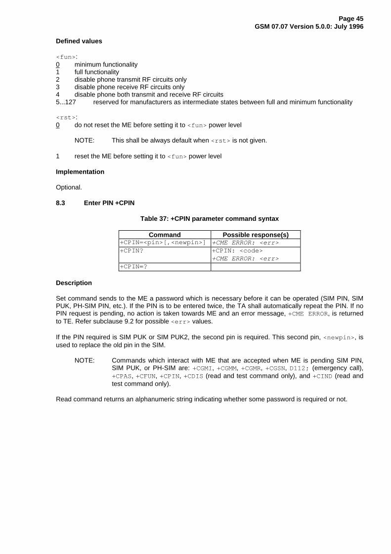
Page 45GSM 07.07 Version 5.0.0: July 1996
Defined values
<fun> :0 minimum functionality1 full functionality2 disable phone transmit RF circuits only3 disable phone receive RF circuits only4 disable phone both transmit and receive RF circuits5...127 reserved for manufacturers as intermediate states between full and minimum functionality
<rst> :0 do not reset the ME before setting it to <fun> power level
NOTE: This shall be always default when <rst> is not given.
1 reset the ME before setting it to <fun> power level
Implementation
Optional.
8.3 Enter PIN +CPIN
Table 37: +CPIN parameter command syntax
Command Possible response(s)+CPIN=<pin>[,<newpin>] +CME ERROR: <err>+CPIN? +CPIN: <code>
+CME ERROR: <err>+CPIN=?
Description
Set command sends to the ME a password which is necessary before it can be operated (SIM PIN, SIMPUK, PH-SIM PIN, etc.). If the PIN is to be entered twice, the TA shall automatically repeat the PIN. If noPIN request is pending, no action is taken towards ME and an error message, +CME ERROR, is returnedto TE. Refer subclause 9.2 for possible <err> values.
If the PIN required is SIM PUK or SIM PUK2, the second pin is required. This second pin, <newpin> , isused to replace the old pin in the SIM.
NOTE: Commands which interact with ME that are accepted when ME is pending SIM PIN,SIM PUK, or PH-SIM are: +CGMI, +CGMM, +CGMR, +CGSN, D112; (emergency call),+CPAS, +CFUN, +CPIN, +CDIS (read and test command only), and +CIND (read andtest command only).
Read command returns an alphanumeric string indicating whether some password is required or not.

Page 46GSM 07.07 Version 5.0.0: July 1996
Defined values
<pin> , <newpin> : string type values
<code> values reserved by this ETS:READY ME is not pending for any passwordSIM PIN ME is waiting SIM PIN to be givenSIM PUK ME is waiting SIM PUK to be givenPH-SIM PIN ME is waiting PHone-to-SIM card password to be givenSIM PIN2 ME is waiting SIM PIN2 to be given (this <code> is recommended to be returned only
when the last executed command resulted in PIN2 authentication failure (i.e. +CMEERROR: 17 ); if PIN2 is not entered right after the failure, it is recommended that MEdoes not block its operation)
SIM PUK2 ME is waiting SIM PUK2 to be given (this <code> is recommended to be returned onlywhen the last executed command resulted in PUK2 authentication failure (i.e. +CMEERROR: 18 ); if PUK2 and new PIN2 are not entered right after the failure, it isrecommended that ME does not block its operation)
Implementation
Optional.
8.4 Battery charge +CBC
Table 38: +CBC action command syntax
Command Possible response(s)+CBC +CBC: <bcs>,<bcl>
+CME ERROR: <err>+CBC=? +CBC: ( list of supported <bcs> s),( list of supported <bcl> s)
Description
Execution command returns battery connection status <bcs> and battery charge level <bcl> of the ME.Refer subclause 9.2 for possible <err> values.
Test command returns values supported by the TA as compound values.
Defined values
<bcs> :0 ME is powered by the battery1 ME has a battery connected, but is not powered by it2 ME does not have a battery connected3 Recognized power fault, calls inhibited
<bcl> :0 battery is exhausted, or ME does not have a battery connected1...100 battery has 1-100 percent of capacity remaining
Implementation
Optional.

Page 47GSM 07.07 Version 5.0.0: July 1996
8.5 Signal quality +CSQ
Table 39: +CSQ action command syntax
Command Possible response(s)+CSQ +CSQ: <rssi>,<ber>
+CME ERROR: <err>+CSQ=? +CSQ: ( list of supported <rssi> s),( list of supported <ber> s)
Description
Execution command returns received signal strength indication <rssi> and channel bit error rate <ber>from the ME. Refer subclause 9.2 for possible <err> values.
Test command returns values supported by the TA as compound values.
Defined values
<rssi> :0 -113 dBm or less1 -111 dBm2...30 -109... -53 dBm31 -51 dBm or greater99 not known or not detectable
<ber> (in percent):0...7 as RXQUAL values in the table in GSM 05.08 [20] subclause 8.2.499 not known or not detectable
Implementation
Optional.
8.6 Mobile Equipment control mode +CMEC
Table 40: +CMEC parameter command syntax
Command Possible response(s)+CMEC=[<keyp>[,<disp>[,<ind>]]] +CME ERROR: <err>+CMEC? +CMEC: <keyp>,<disp>,<ind>+CMEC=? +CMEC: ( list of supported <keyp> s),( list of
supported <disp> s),( list of supported <ind> s)
Description
Set command selects the equipment, which operates ME keypad, writes to ME display and sets MEindicators. If operation mode is not allowed by the ME, +CME ERROR: <err> is returned. Refersubclause 9.2 for <err> values.
Test command returns the modes supported by the TA as compound values.

Page 48GSM 07.07 Version 5.0.0: July 1996
Defined values
<keyp> :0 ME can be operated only through its keypad (execute command of +CKPD cannot be used)1 ME can be operated only from TE (with command +CKPD)2 ME can be operated from both ME keypad and TE
<disp> :0 only ME can write to its display (command +CDIS can only be used to read the display)1 only TE can write to ME display (with command +CDIS)2 ME display can be written by both ME and TE
<ind> :0 only ME can set the status of its indicators (command +CIND can only be used to read the
indicators)1 only TE can set the status of ME indicators (with command +CIND)2 ME indicators can be set by both ME and TE
Implementation
Mandatory when any of keypad, display or indicator commands is implemented.
8.7 Keypad control +CKPD
Table 41: +CKPD action command syntax
Command Possible response(s)+CKPD=<keys>[,<time>[,<pause>]] +CME ERROR: <err>+CKPD=?
Description
Execution command emulates ME keypad by giving each keystroke as a character in a string <keys> .<time> *0.1 seconds is the time to stroke each key and <pause> *0.1 seconds is the length of pausebetween two strokes. If emulating fails in an ME error, +CME ERROR: <err> is returned. Refersubclause 9.2 for <err> values. This command should be accepted (OK returned) before actually startingto press the keys. Thus unsolicited result codes of key pressings and display events can be returned(refer subclause "Mobile Equipment event reporting +CMER").
Defined values
<keys> : string of characters representing keys as listed in the following table (based on PCCAXANX-101-I table I-3). Colon character (IRA 58) followed by one character can be used to indicatea manufacturer specific key not listed here. All characters from a semicolon character (IRA 59) tothe next single semicolon character are treated as alpha entries and are not converted to keyequivalents. All semicolon characters inside alpha entries should be duplicated in the TE andstripped to one before entering to the ME. Pause character (IRA 87 or 119) can be used to pausebetween key pressings for a time specified by <pause> . All IRA values not listed here are reserved.

Page 49GSM 07.07 Version 5.0.0: July 1996
Table 42: Character codes
Char IRA (dec) Comment (+ some known key symbols)# 35 hash (number sign)% 37 percent sign (P)* 42 star (*)0... 9 48... 57 number keys: 58 escape character for manufacturer specific keys; 59 escape character for string entering< 60 left arrow> 62 right arrow@ 64 alpha key (α/ABC)A/a 65/97 channel A (A)B/b 66/98 channel B (B)C/c 67/99 clear display (C/CLR)D/d 68/100 volume downE/e 69/101 connection end (END)F/f 70/102 function (FCN)L/l 76/108 phone lock (LOCK)M/m 77/109 menu (MENU)P/p 80/112 power (PWR)Q/q 81/113 quiet/mute (MUTE)R/r 82/114 recall last number (R/RCL/MR)S/s 83/115 connection start (SEND)T/t 84/116 store/ memory (STO/M/M+)U/u 85/117 volume upV/v 86/118 down arrowW/w 87/119 pause characterX/x 88/120 auxiliary (AUX)Y/y 89/121 delete last character (C)[ 91 soft key 1] 93 soft key 2^ 94 up arrow
<time> , <pause> :0...255 0... 25.5 seconds (default values are manufacturer specific, but should be so long that a
normal ME can handle keystrokes correctly)
Implementation
Optional.
8.8 Display control +CDIS
Table 43: +CDIS parameter command syntax
Command Possible response(s)+CDIS=[<text>[,<text>[,...]]] +CME ERROR: <err>+CDIS? +CDIS: <text>[,<text>[,...]]
+CME ERROR: <err>+CDIS=? +CDIS: <length>[,<length>[,...]]
+CME ERROR: <err>
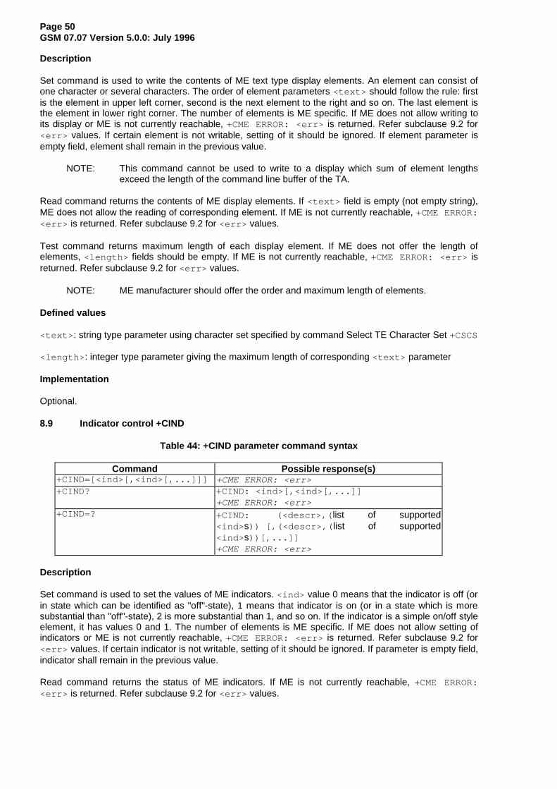
Page 50GSM 07.07 Version 5.0.0: July 1996
Description
Set command is used to write the contents of ME text type display elements. An element can consist ofone character or several characters. The order of element parameters <text> should follow the rule: firstis the element in upper left corner, second is the next element to the right and so on. The last element isthe element in lower right corner. The number of elements is ME specific. If ME does not allow writing toits display or ME is not currently reachable, +CME ERROR: <err> is returned. Refer subclause 9.2 for<err> values. If certain element is not writable, setting of it should be ignored. If element parameter isempty field, element shall remain in the previous value.
NOTE: This command cannot be used to write to a display which sum of element lengthsexceed the length of the command line buffer of the TA.
Read command returns the contents of ME display elements. If <text> field is empty (not empty string),ME does not allow the reading of corresponding element. If ME is not currently reachable, +CME ERROR:<err> is returned. Refer subclause 9.2 for <err> values.
Test command returns maximum length of each display element. If ME does not offer the length ofelements, <length> fields should be empty. If ME is not currently reachable, +CME ERROR: <err> isreturned. Refer subclause 9.2 for <err> values.
NOTE: ME manufacturer should offer the order and maximum length of elements.
Defined values
<text> : string type parameter using character set specified by command Select TE Character Set +CSCS
<length> : integer type parameter giving the maximum length of corresponding <text> parameter
Implementation
Optional.
8.9 Indicator control +CIND
Table 44: +CIND parameter command syntax
Command Possible response(s)+CIND=[<ind>[,<ind>[,...]]] +CME ERROR: <err>+CIND? +CIND: <ind>[,<ind>[,...]]
+CME ERROR: <err>+CIND=? +CIND: (<descr>,( list of supported
<ind> s)) [,(<descr>,( list of supported<ind> s))[,...]]+CME ERROR: <err>
Description
Set command is used to set the values of ME indicators. <ind> value 0 means that the indicator is off (orin state which can be identified as "off"-state), 1 means that indicator is on (or in a state which is moresubstantial than "off"-state), 2 is more substantial than 1, and so on. If the indicator is a simple on/off styleelement, it has values 0 and 1. The number of elements is ME specific. If ME does not allow setting ofindicators or ME is not currently reachable, +CME ERROR: <err> is returned. Refer subclause 9.2 for<err> values. If certain indicator is not writable, setting of it should be ignored. If parameter is empty field,indicator shall remain in the previous value.
Read command returns the status of ME indicators. If ME is not currently reachable, +CME ERROR:<err> is returned. Refer subclause 9.2 for <err> values.

Page 51GSM 07.07 Version 5.0.0: July 1996
Test command returns pairs, where string value <descr> is a maximum 16 character description of theindicator and compound value is the allowed values for the indicator. If ME is not currently reachable,+CME ERROR: <err> is returned. Refer subclause 9.2 for <err> values.
NOTE: ME manufacturer should offer the description of supported indicators not listed hereand their value ranges and default values.
Defined values
<ind> : integer type value, which shall be in range of corresponding <descr>
<descr> values reserved by this ETS and their <ind> ranges:"battchg" battery charge level (0-5)"signal" signal quality (0-5)"service" service availability (0-1)"sounder" sounder activity (0-1)"message" message received (0-1)"call" call in progress (0-1)"vox" transmit activated by voice activity (0-1)"roam" roaming indicator (0-1)"smsfull" a short message memory storage in the MT has become full (1), or memory locations are
available (0); i.e. the range is (0-1)
Implementation
Optional.
8.10 Mobile Equipment event reporting +CMER
Table 45: +CMER parameter command syntax
Command Possible response(s)+CMER=[<mode>[,<keyp>[,<disp>[,<ind>[,<bfr>]]]]]
+CME ERROR: <err>
+CMER? +CMER: <mode>,<keyp>,<disp>,<ind>,<bfr>+CMER=? +CMER: ( list of supported <mode>s),( list of supported
<keyp> s),( list of supported <disp> s),( list of supported<ind> s),( list of supported <bfr> s)
Description
Set command enables or disables sending of unsolicited result codes from TA to TE in the case of keypressings, display changes, and indicator state changes. <mode> controls the processing of unsolicitedresult codes specified within this command. <bfr> controls the effect on buffered codes when <mode> 1,2 or 3 is entered. If setting is not supported by the ME, +CME ERROR: <err> is returned. Refersubclause 9.2 for <err> values.
Test command returns the modes supported by the TA as compound values.
Defined values
<mode>:0 buffer unsolicited result codes in the TA; if TA result code buffer is full, codes can be buffered in
some other place or the oldest ones can be discarded1 discard unsolicited result codes when TA-TE link is reserved (e.g. in on-line data mode); otherwise
forward them directly to the TE2 buffer unsolicited result codes in the TA when TA-TE link is reserved (e.g. in on-line data mode)
and flush them to the TE after reservation; otherwise forward them directly to the TE3 forward unsolicited result codes directly to the TE; TA-TE link specific inband technique used to
embed result codes and data when TA is in on-line data mode

Page 52GSM 07.07 Version 5.0.0: July 1996
<keyp> :0 no keypad event reporting1 keypad event reporting using result code +CKEV: <key>,<press> . <key> indicates the key
(refer IRA values defined in table in subclause "Keypad control +CKPD") and <press> if the key ispressed or released (1 for pressing and 0 for releasing). Only those key pressings, which are notcaused by +CKPD shall be indicated by the TA to the TE.
NOTE: When this mode is enabled, corresponding result codes of all keys currently pressedshould be flushed to the TA regardless of <bfr> setting.
2 keypad event reporting using result code +CKEV: <key>,<press> . All key pressings shall bedirected from TA to TE.
NOTE: When this mode is enabled, corresponding result codes of all keys currently pressedshould be flushed to the TA regardless of <bfr> setting.
<disp> :0 no display event reporting1 display event reporting using result code +CDEV: <elem>,<text> . <elem> indicates the element
order number (as specified for +CDIS) and <text> is the new value of text element. Only thosedisplay events, which are not caused by +CDIS shall be indicated by the TA to the TE. Characterset used in <text> is as specified by command Select TE Character Set +CSCS
2 display event reporting using result code +CDEV: <elem>,<text> . All display events shall bedirected from TA to TE. Character set used in <text> is as specified by command Select TECharacter Set +CSCS
<ind> :0 no indicator event reporting1 indicator event reporting using result code +CIEV: <ind>,<value> . <ind> indicates the
indicator order number (as specified for +CIND) and <value> is the new value of indicator. Onlythose indicator events, which are not caused by +CIND shall be indicated by the TA to the TE
2 indicator event reporting using result code +CIEV: <ind>,<value> . All indicator events shall bedirected from TA to TE
<bfr> :0 TA buffer of unsolicited result codes defined within this command is cleared when <mode> 1...3 is
entered1 TA buffer of unsolicited result codes defined within this command is flushed to the TE when
<mode> 1...3 is entered (OK response shall be given before flushing the codes)
Implementation
Mandatory when any of the keypad, display, or indicator result codes is implemented.
8.11 Select phonebook memory storage +CPBS
Table 46: +CPBS parameter command syntax
Command Possible response(s)+CPBS=<storage> +CME ERROR: <err>+CPBS? +CPBS: <storage>[,<used>,<total>]
+CME ERROR: <err>+CPBS=? +CPBS: ( list of supported <storage> s)

Page 53GSM 07.07 Version 5.0.0: July 1996
Description
Set command selects phonebook memory storage <storage> , which is used by other phonebookcommands. If setting fails in an ME error, +CME ERROR: <err> is returned. Refer subclause 9.2 for<err> values.
Read command returns currently selected memory, and when supported by manufacturer, number ofused locations and total number of locations in the memory.
Test command returns supported storages as compound value.
Defined values
<storage> values reserved by this ETS:"FD" SIM fixdialling-phonebook"LD" SIM last-dialling-phonebook"ME" ME phonebook"MT" combined ME and SIM phonebook"SM" SIM phonebook"TA" TA phonebook
<used> : integer type value indicating the number of used locations in selected memory
<total> : integer type value indicating the total number of locations in selected memory
Implementation
Mandatory when phonebook read, find or write command, or direct dialling (refer subclause "Direct diallingfrom phonebooks") is implemented.
8.12 Read phonebook entries +CPBR
Table 47: +CPBR action command syntax
Command Possible response(s)+CPBR=<index1>[,<index2>] +CPBR: <index1>,<number>,<type>,<text>[[...]
<CR><LF>+CPBR: <index2>,<number>,<type>,<text>]+CME ERROR: <err>
+CPBR=? +CPBR: ( list of supported <index> s),<nlength>,<tlength>+CME ERROR: <err>
Description
Execution command returns phonebook entries in location number range <index1> ... <index2> fromthe current phonebook memory storage selected with +CPBS. If <index2> is left out, only location<index1> is returned. Entry fields returned are location number <index n>, phone number stored there<number> (of format <type> ) and text <text> associated with the number. If listing fails in an ME error,+CME ERROR: <err> is returned. Refer subclause 9.2 for <err> values.
Test command returns location range supported by the current storage as a compound value and themaximum lengths of <number> and <text> fields. If ME is not currently reachable, +CME ERROR:<err> is returned. Refer subclause 9.2 for <err> values.
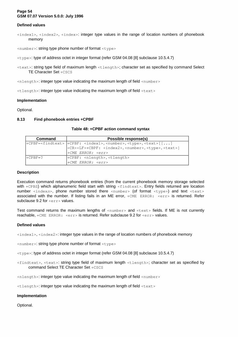
Page 54GSM 07.07 Version 5.0.0: July 1996
Defined values
<index1> , <index2> , <index> : integer type values in the range of location numbers of phonebookmemory
<number> : string type phone number of format <type>
<type> : type of address octet in integer format (refer GSM 04.08 [8] subclause 10.5.4.7)
<text> : string type field of maximum length <tlength> ; character set as specified by command SelectTE Character Set +CSCS
<nlength> : integer type value indicating the maximum length of field <number>
<tlength> : integer type value indicating the maximum length of field <text>
Implementation
Optional.
8.13 Find phonebook entries +CPBF
Table 48: +CPBF action command syntax
Command Possible response(s)+CPBF=<findtext> +CPBF: <index1>,<number>,<type>,<text>[[...]
<CR><LF>+CBPF: <index2>,<number>,<type>,<text>]+CME ERROR: <err>
+CPBF=? +CPBF: <nlength>,<tlength>+CME ERROR: <err>
Description
Execution command returns phonebook entries (from the current phonebook memory storage selectedwith +CPBS) which alphanumeric field start with string <findtext> . Entry fields returned are locationnumber <index n>, phone number stored there <number> (of format <type> ) and text <text>associated with the number. If listing fails in an ME error, +CME ERROR: <err> is returned. Refersubclause 9.2 for <err> values.
Test command returns the maximum lengths of <number> and <text> fields. If ME is not currentlyreachable, +CME ERROR: <err> is returned. Refer subclause 9.2 for <err> values.
Defined values
<index1> , <index2> : integer type values in the range of location numbers of phonebook memory
<number> : string type phone number of format <type>
<type> : type of address octet in integer format (refer GSM 04.08 [8] subclause 10.5.4.7)
<findtext> , <text> : string type field of maximum length <tlength> ; character set as specified bycommand Select TE Character Set +CSCS
<nlength> : integer type value indicating the maximum length of field <number>
<tlength> : integer type value indicating the maximum length of field <text>
Implementation
Optional.

Page 55GSM 07.07 Version 5.0.0: July 1996
8.14 Write phonebook entry +CPBW
Table 49: +CPBW action command syntax
Command Possible response(s)+CPBW=[<index>][,<number> [,<type>[,<text>]]]
+CME ERROR: <err>
+CPBW=? +CPBW: ( list of supported <index> s),<nlength>,( listof supported <type> s),<tlength>+CME ERROR: <err>
Description
Execution command writes phonebook entry in location number <index> in the current phonebookmemory storage selected with +CPBS. Entry fields written are phone number <number> (in the format<type> ) and text <text> associated with the number. If those fields are omitted, phonebook entry isdeleted. If <index> is left out, but <number> is given, entry is written to the first free location in thephonebook (the implementation of this feature is manufacturer specific). If writing fails in an ME error,+CME ERROR: <err> is returned. Refer subclause 9.2 for <err> values.
Test command returns location range supported by the current storage as a compound value, themaximum length of <number> field, supported number formats of the storage, and the maximum lengthof <text> field. If ME is not currently reachable, +CME ERROR: <err> is returned. Refer subclause 9.2for <err> values. If storage does not offer format information, the format list should be emptyparenthesis.
Defined values
<index> : integer type values in the range of location numbers of phonebook memory
<number> : string type phone number of format <type>
<type> : type of address octet in integer format (refer GSM 04.08 [8] subclause 10.5.4.7) ; default 145 when dialling string includes international access code character "+", otherwise 129
<text> : string type field of maximum length <tlength> ; character set as specified by command Select TE Character Set +CSCS
<nlength> : integer type value indicating the maximum length of field <number>
<tlength> : integer type value indicating the maximum length of field <text>
Implementation
Optional.
8.15 Clock +CCLK
Table 50: +CCLK parameter command syntax
Command Possible response(s)+CCLK=<time> +CME ERROR: <err>+CCLK? +CCLK: <time>
+CME ERROR: <err>+CCLK=?

Page 56GSM 07.07 Version 5.0.0: July 1996
Description
Set command sets the real-time clock of the ME. If setting fails in an ME error, +CME ERROR: <err> isreturned. Refer subclause 9.2 for <err> values.
Read command returns the current setting of the clock.
Defined values
<time> : string type value; format is "yy/MM/dd,hh:mm:ss±zz", where characters indicate year (two lastdigits), month, day, hour, minutes, seconds and time zone (indicates the difference, expressed in quarters of an hour, between the local time and GMT; range -47...+48). E.g. 6th of May 1994, 22:10:00 GMT+2 hours equals to "94/05/06,22:10:00+08"
Implementation
Optional.
8.16 Alarm +CALA
Table 51: +CALA parameter command syntax
Command Possible response(s)+CALA=<time>[,<n>[,<type>[,<text>]]] +CME ERROR: <err>+CALA? +CALA: <time>,<n>,<type>,<text>
[<CR><LF>+CALA: <time>,<n>,<type>,<text>[...]]+CME ERROR: <err>
+CALA=? +CALA: ( list of supported <n>s),( list of supported<type> s),<tlength>+CME ERROR: <err>
Description
Set command sets an alarm time in the ME. There can be an array of different types of alarms, and eachalarm may cause different text to be displayed in the ME display. If setting fails in an ME error, +CMEERROR: <err> is returned. Refer subclause 9.2 for <err> values.
Read command returns the list of current alarm settings in the ME.
Test command returns supported array index values, alarm types, and maximum length of the text to bedisplayed.
Defined values
<time> : refer +CCLK
<n>: integer type value indicating the index of the alarm; default is manufacturer specific
<type> : integer type value indicating the type of the alarm (e.g. sound, volume, LED); values and default are manufacturer specific
<text> : string type value indicating the text to be displayed when alarm time is reached; maximum length <tlength>
<tlength> : integer type value indicating the maximum length of <text>
Implementation
Optional.

Page 57GSM 07.07 Version 5.0.0: July 1996
8.17 Generic SIM access +CSIM
Table 52: +CSIM action command syntax
Command Possible response(s)+CSIM=<length>,<command> +CSIM: <length>,<response>
+CME ERROR: <err>+CSIM=?
Description
Set command transmits to the ME the <command> it then shall send as it is to the SIM. In the samemanner the SIM <response> shall be sent back by the ME to the TA as it is. Refer subclause 9.2 for<err> values.
This command allows a direct control of the SIM by an distant application on the TE. The TE shall thentake care of processing SIM information within the frame specified by GSM.
Defined values
<length> : integer type; length of the characters that are sent to TE in <command> or <response> (two times the actual length of the command or response)
<command> : command passed on by the ME to the SIM in the format as described in TS GSM 11.11 (hexadecimal character format; refer +CSCS)
<response> : response to the command passed on by the SIM to the ME in the format as described in TS GSM 11.11 (hexadecimal character format; refer +CSCS)
Implementation
Optional.
8.18 Informative examples
Phone Activity Status (+CPAS) is a general command used to detect the presence of the ME, if there is anincoming call, or if there is a call in progress. This command should be used before trying to operate theME from the TE. Note that the activity status may change at any time after the execution of +CPAS, andhence the returned value may be obsolete. Detachment of the ME from the TA is indicated with a specialfinal result code that indicates all errors related to the operation of the ME. Result code is +CME ERROR:<err> , where <err> is an integer or verbose value giving useful information about the reason for thecommand failure (refer subclause "Mobile Equipment error result code +CME ERROR").
Set Phone Functionality (+CFUN) can be used to reset the ME or set the power consumption level of theME by disabling certain parts of the ME (e.g. the transmit and receive RF circuits). Mobile EquipmentControl Mode (+CMEC) is a command which manages access sharing between the ME and the TE tooperate the user interface of the ME. It has three subparameters which describe the access to keypad,display and indicators. Each subparameter has values for restricting the operation of the correspondinguser interface part only to the ME or only to the TE, or to give the access for both of them.
Keypad Control command (+CKPD) is used to operate the keypad of the ME. Here lies the problem ofdifferent keypad types between manufacturers, and also between their ME models. The keypresses aresent to the ME as a string type subparameter of this command. Each character in that string represents akey which will be logically pressed. A special character (colon) followed by any character can be used bymanufacturers (or TE application programmers) to represent a key which is not defined in this profile. Anescape character (semicolon) for direct string entering is also defined. All text between single semicoloncharacters is treated as an alphanumeric entry and is not converted to keypressings. All semicoloncharacters inside the text shall be duplicated in the TE and stripped back to one before entering them tothe ME. Command has also optional second and third parameters which can be used to alter the time tostrike each key, and the pause to wait between keystrokes (in tenths of a second). A special pausecharacter (W or w) may be added in the string type subparameter for an extra pause of the same length

Page 58GSM 07.07 Version 5.0.0: July 1996
as given by the third subparameter. In the following example alphanumeric mode is entered and a personpredefined in the ME phonebook, "Ilkka", is called; each key is struck for half a second and pausesbetween strokes are a tenth of a second:
AT+CKPD="@:Ilkka:S",5,1OK
Display Control command (+CDIS) is used both for writing to the display text fields and for reading thecurrent status of the fields. Mobile equipment usually have a character set of their own, so the TA shall beable to do a conversion between the TE and the ME character sets. TE can have several character setsand the TA must be informed of the character set in use before starting to write or read the display.Character set is set with general command Select TE Character Set +CSCS. The +CDIS=? querycommand is a way to get information about the length of the fields. In the following example an ME is firstqueried about the supported conversions and the lengths of the fields. The response shows there arethree ten character long and two six character long fields. Then the TE character set is set to be IRA andthe current status of the display is read. The last command writes the text "Hello, I'm writing to display" inthe three fields, and keeps the contents of the two other fields same (the last two commas could also beleft out).
AT+CSCS=?;+CDIS=?+CSCS: ("IRA","PCCP850","8859-1")+CDIS: 10,10,10,6,6OKAT+CSCS="IRA"OKAT+CDIS?+CDIS: "RADIOLINJA","","","Menu","Memory"OKAT+CDIS="IRA","Hello, I'm","writing to","display",,OK
The writing is possible only when it is permitted by the Mobile Equipment Control Mode command (and bythe manufacturer). If a certain field is not writable (but is readable), writing to it should be ignored. Theorder of the text fields should be determined by manufacturers and follow the rule: first field is in the upperleft corner, second in the next field to the right, and so on, until to the last field in the lower right corner.
Indicators can be handled with Indicator Control command (+CIND). Its query command returns a shortdescription (abbreviation) of the purpose of the indicators and the supported values for each indicator. Thesetting and reading is done similarly as with Display Control command. In the following example theindicators of a phone are queried, their current value is read, and the value of message indicator is tried toset (but it is forbidden). Although the battery charge indicator has only four different states, five areemulated by giving two integers for the two most charged states.
AT+CIND=?+CIND: ("memory",(0-2)),("call",(0,1)),("data",(0,1)),("roam",(0,1)),("alpha",(0,1)),("message",(0,1)),("index1",(0-11)),("index2",(0-11)),("index3",(0-11)),("signal",(0-5)),("service",(0,1)),("sel1",(0,1)),("sel2",(0,1)),("sel3",(0,1)),("battchg",(0-5))OKAT+CIND?+CIND: 1,0,0,0,0,1,0,0,0,3,1,0,0,0,5OKAT+CIND=,,,,,0+CME ERROR: 10
The subparameter order in the command is defined by the query command order, not by the actualdisplay order. The zero value of an indicator means that it is off (or in state which can be identified as"off"-state), value one means that the indicator is on (or in a state which is more substantial than"off"-state), value two is more substantial than one, and so on.
To this point, only operating through the TE is covered. But when ME can be operated also through itskeypad, or there are changes in the status of the display elements, the information about these actionsshall be given to the TE also. This can be solved only with unsolicited result codes which return keypad,display text and indicator events. Each event group has a result code of its own: +CKEV returns the keycode and if the key pressed (1) or released (0), +CDEV returns the display text field running number (as

Page 59GSM 07.07 Version 5.0.0: July 1996
specified by command +CDIS) and the new status of the field, and +CIEV returns the running number ofthe indicator (refer +CIND) and the new value of it. In the following example number key 1 is pressed,updated on the display, released, and signal strength changes its state to five:
+CKEV: 49,1+CDEV: 1,"1"+CKEV: 49,0+CIND: 10,5
Mobile Equipment Event Reporting command (+CMER) has been specified for the purpose of controllingthe sending of these unsolicited result codes to the TE. Four ways are provided to handle the buffering ofthe result codes (see figure 8). The first is to buffer them always. The second possibility is to discard themwhen in on-line data mode and otherwise forward them directly to the TE. The third possibility is to bufferthem in data mode and otherwise forward them to the TE. The last possibility is to send them always tothe TE (some inband technique shall be used in data mode to send the result codes within the data). Thisis the first subparameter of +CMER command. Next three subparameters are used to enable or disableeach of the keypad, text field and indicator result codes. Sending codes can be enabled either so that onlyevents generated from the ME user interface are returned, or so that also events caused by Keypad,Display and Indicator Control commands are returned. The fifth subparameter controls the flushing of thebuffer when the value of the first subparameter is changed to a value from one to three.
COMMAND MODE
DATA MODE
Buffer
TE
ME
TA
ME events (inband)
0
1
2
3
+CMER firstsubparameter
Figure 8: Mobile equipment event reporting
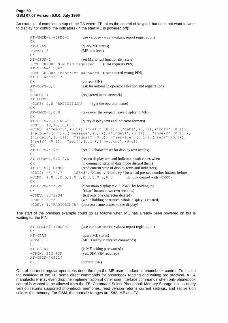
Page 60GSM 07.07 Version 5.0.0: July 1996
An example of complete setup of the TA where TE takes the control of keypad, but does not want to writeto display nor control the indicators (in the start ME is powered off):
AT+CMEE=2;+CREG=1 (use verbose <err> values; report registration)OKAT+CPAS (query ME status)+CPAS: 5 (ME is asleep)OKAT+CFUN=1 (set ME to full functionality state)+CME ERROR: SIM PIN required (SIM requests PIN)AT+CPIN="1234"+CME ERROR: incorrect password (user entered wrong PIN)AT+CPIN="4321"OK (correct PIN)AT+COPS=0,0 (ask for automatic operator selection and registration)OK+CREG: 1 (registered in the network)AT+COPS?+COPS: 0,0,"RADIOLINJA" (get the operator name)OKAT+CMEC=1,0,0 (take over the keypad, leave display to ME)OKAT+CDIS=?;+CIND=? (query display text and indicator formats)+CDIS: 10,10,10,6,6+CIND: ("memory",(0-2)),("call",(0,1)),("data",(0,1)),("roam",(0,1)),("alpha",(0,1)),("message",(0,1)),("index1",(0-11)),("index2",(0-11)),("index3",(0-11)),("signal",(0-5)),("service",(0,1)),("sel1",(0,1)),("sel2",(0,1)),("sel3",(0,1)),("battchg",(0-5))OKAT+CSCS="IRA" (set TE character set for display text results)OKAT+CMER=1,0,2,2,0 (return display text and indicator result codes whenOK in command state, in data mode discard them)AT+CDIS?;+CIND? (read current state of display texts and indicators)+CDIS: "",""," 12345","Menu","Memory" (user had pressed number buttons before+CIND: 1,0,0,0,0,1,0,0,0,3,1,0,0,0,5 TE took control with +CMEC)OKAT+CKPD="C",20 (clear main display text "12345" by holding theOK "clear" button down two seconds)+CDEV: 3,"1234" (first only one character deleted)+CDEV: 3,"" (while holding continues, whole display is cleared)+CDEV: 1,"RADIOLINJA" (operator name comes to the display)
The start of the previous example could go as follows when ME has already been powered on but iswaiting for the PIN:
AT+CMEE=2;+CREG=1 (use verbose <err> values; report registration)OKAT+CPAS (query ME status)+CPAS: 0 (ME is ready to receive commands)OKAT+CPIN? (is ME asking passwords?)+CPIN: SIM PIN (yes, SIM PIN required)AT+CPIN="4321"OK (correct PIN)
One of the most regular operations done through the ME user interface is phonebook control. To lessenthe workload of the TE, some direct commands for phonebook reading and writing are practical. A TAmanufacturer may even drop the implementation of other user interface commands when only phonebookcontrol is wanted to be allowed from the TE. Command Select Phonebook Memory Storage +CPBS queryversion returns supported phonebook memories, read version returns current settings, and set versionselects the memory. For GSM, the normal storages are SIM, ME and TA.
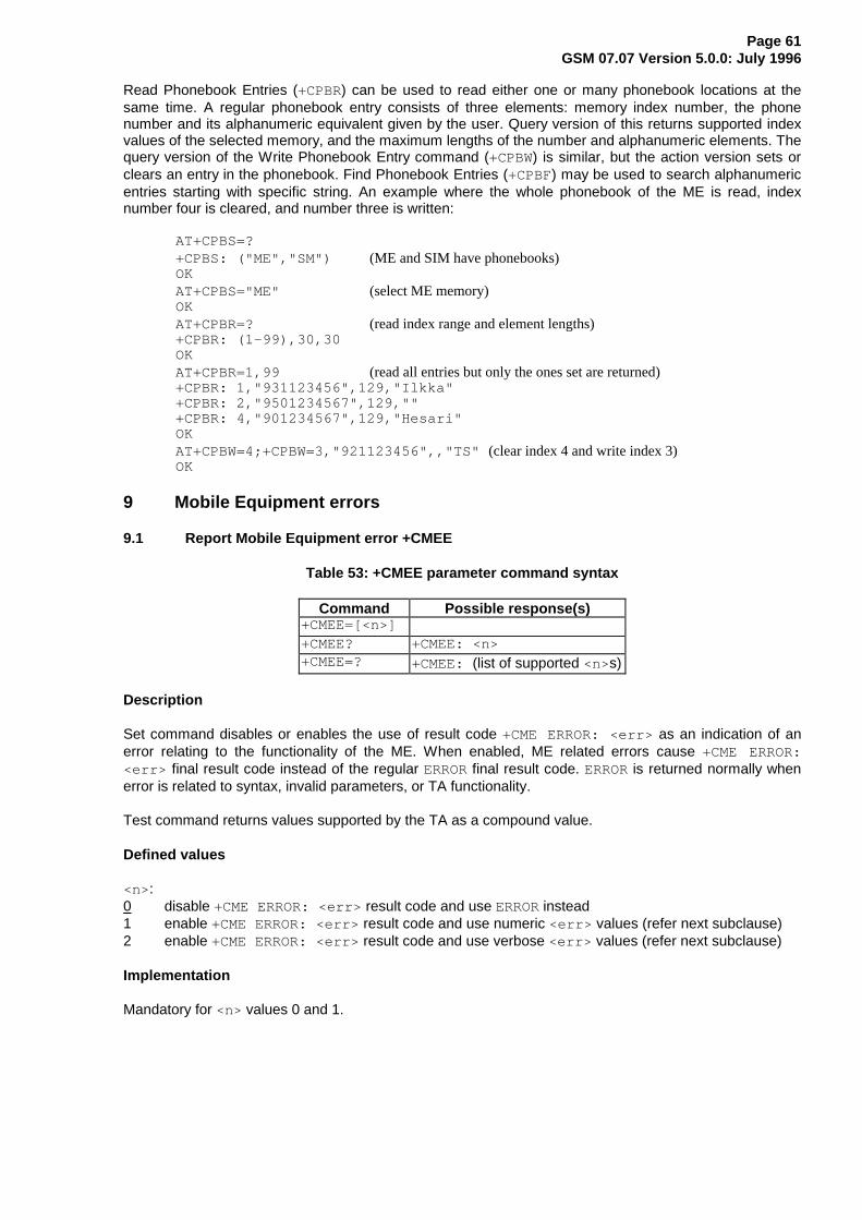
Page 61GSM 07.07 Version 5.0.0: July 1996
Read Phonebook Entries (+CPBR) can be used to read either one or many phonebook locations at thesame time. A regular phonebook entry consists of three elements: memory index number, the phonenumber and its alphanumeric equivalent given by the user. Query version of this returns supported indexvalues of the selected memory, and the maximum lengths of the number and alphanumeric elements. Thequery version of the Write Phonebook Entry command (+CPBW) is similar, but the action version sets orclears an entry in the phonebook. Find Phonebook Entries (+CPBF) may be used to search alphanumericentries starting with specific string. An example where the whole phonebook of the ME is read, indexnumber four is cleared, and number three is written:
AT+CPBS=?+CPBS: ("ME","SM") (ME and SIM have phonebooks)OKAT+CPBS="ME" (select ME memory)OKAT+CPBR=? (read index range and element lengths)+CPBR: (1-99),30,30OKAT+CPBR=1,99 (read all entries but only the ones set are returned)+CPBR: 1,"931123456",129,"Ilkka"+CPBR: 2,"9501234567",129,""+CPBR: 4,"901234567",129,"Hesari"OKAT+CPBW=4;+CPBW=3,"921123456",,"TS" (clear index 4 and write index 3)OK
9 Mobile Equipment errors
9.1 Report Mobile Equipment error +CMEE
Table 53: +CMEE parameter command syntax
Command Possible response(s)+CMEE=[<n>]+CMEE? +CMEE: <n>+CMEE=? +CMEE: (list of supported <n>s)
Description
Set command disables or enables the use of result code +CME ERROR: <err> as an indication of anerror relating to the functionality of the ME. When enabled, ME related errors cause +CME ERROR:<err> final result code instead of the regular ERROR final result code. ERROR is returned normally whenerror is related to syntax, invalid parameters, or TA functionality.
Test command returns values supported by the TA as a compound value.
Defined values
<n>:0 disable +CME ERROR: <err> result code and use ERROR instead1 enable +CME ERROR: <err> result code and use numeric <err> values (refer next subclause)2 enable +CME ERROR: <err> result code and use verbose <err> values (refer next subclause)
Implementation
Mandatory for <n> values 0 and 1.

Page 62GSM 07.07 Version 5.0.0: July 1996
9.2 Mobile Equipment error result code +CME ERROR
The operation of +CME ERROR: <err> result code is similar to the regular ERROR result code: if +CMEERROR: <err> is the result code for any of the commands in a command line, none of the followingcommands in the same command line is executed (neither ERROR nor OK result code shall be returned asa result of a completed command line execution). The format of <err> can be either numeric or verbose.This is set with command +CMEE (refer previous subclause).
NOTE: ITU-T V.25ter [14] command V does not affect the format of this result code.
<err> values (numeric format followed by verbose format):0 phone failure1 no connection to phone2 phone-adaptor link reserved3 operation not allowed4 operation not supported5 PH-SIM PIN required10 SIM not inserted11 SIM PIN required12 SIM PUK required13 SIM failure14 SIM busy15 SIM wrong16 incorrect password17 SIM PIN2 required18 SIM PUK2 required20 memory full21 invalid index22 not found23 memory failure24 text string too long25 invalid characters in text string26 dial string too long27 invalid characters in dial string30 no network service31 network timeout100 unknownalso all other values below 256 are reserved by this ETS
Implementation
Mandatory for numeric format codes applicable to implemented command set.
9.3 Informative examples
An example of TA responses with all three +CMEE values when ME manufacturer identification isrequested but ME is not connected to the TA:
AT+CMEE=0 (+CME ERROR shall not be used)OKAT+CGMIERRORAT+CMEE=1 (use numeric <err> )OKAT+CGMI+CME ERROR: 1AT+CMEE=2 (use verbose <err> )OKAT+CGMI+CME ERROR: no connection to phone

Page 63GSM 07.07 Version 5.0.0: July 1996
Annex A (normative): Summary of commands from other standards
Summary of ITU-T Recommendation V.25ter [14] commands applicable to GSM:
Table A.1: V.25ter commands applicable to GSM
Name V.25tersection
Description Subclauses in thisETS
&C 6.2.8 Circuit 109 (Received line signal detector) Behaviour 4.3.&D 6.2.9 Circuit 108 (Data terminal ready) Behaviour 4.3.&F 6.1.2 Set to Factory-defined Configuration 5.6./ 3.+DR 6.6.2 Data Compression Reporting 6.13.+DS 6.6.1 Data Compression 6.13.+GCAP 6.1.9 Request Complete Capabilities List 5.6.+GCI 6.1.10 Country of Installation 5.6.+GMI 6.14 Request Manufacturer Identification 5.6./ 5.1.+GMM 6.1.5 Request Model Identification 5.6./ 5.2.+GMR 6.1.6 Request Revision Identification 5.6./ 5.3.+GOI 6.1.8 Request Global Object Identification 5.6.+GSN 6.1.7 Request Product Serial Number Identification 5.6./ 5.4.+ICF 6.2.11 DTE-DCE Character Framing 4.3.+IFC 6.2.12 DTE-DCE Local Flow Control 4.3.+ILRR 6.2.13 DTE-DCE Local Rate Reporting 4.3.+IPR 6.2.10 Fixed DTE Rate 4.3.A 6.3.5 Answer 6.12./ 6.6.D 6.3.1 Dial 6.1.-6.4./ 6.6.E 6.2.4 Command Echo 4.3.H 6.3.6 Hook Control 6.12./ 6.5./ 6.6.I 6.1.3 Request Identification Information 5.6.L 6.3.13 Monitor Speaker Loudness 6.12.M 6.3.14 Monitor Speaker Mode 6.12.O 6.3.7 Return to Online Data State 6.12.P 6.3.3 Select Pulse Dialling 6.12.Q 6.2.5 Result Code Suppression 4.3.S0 6.3.8 Automatic Answer 6.12.S10 6.3.12 Automatic Disconnect Delay 6.12.S3 6.2.1 Command Line Termination Character 4.3.S4 6.2.2 Response Formatting Character 4.3.S5 6.2.3 Command Line Editing Character 4.3.S6 6.3.9 Pause Before Blind Dialling 6.12.S7 6.3.10 Connection Completion Timeout 6.12.S8 6.3.11 Comma Dial Modifier Time 6.12.T 6.3.2 Select Tone Dialling 6.12.V 6.2.6 DCE Response Format 4.3./ 3./ 4.1./ 4.2.X 6.2.7 Result Code Selection and Call Progress Monitoring Control 4.3.Z 6.1.1 Reset To Default Configuration 5.6.
The use of ITU-T Recommendation V.42 error control protocol is not specified for GSM, but if amanufacturer chooses to implement it over transparent data service, +E prefixed commands ofV.25ter [14] shall be used.
ITU-T T.31 [11] and T.32 [12] may be used as facsimile TA-TE protocols without deletions or additions tothe command set.

Page 64GSM 07.07 Version 5.0.0: July 1996
TIA IS-99 [15] commands referenced in this ETS:
Table A.2: TIA IS-99 commands in this ETS
Command IS-99section
Description Subclause inthis ETS
+CBC 5.6.5 Battery Charge 8.4.+CGMI 5.6.10 Request Manufacturer Identification 5.1.+CGMM 5.6.10 Request Model Identification 5.2.+CGMR 5.6.10 Request Revision Identification 5.3.+CGSN 5.6.10 Request Product Serial Number Identification 5.4.+CRC 5.6.7 Cellular Result Codes 6.11.
TIA IS-135 [16]commands referenced in this ETS:
Table A.3: TIA IS-135 commands in this ETS
Command IS-135section
Description Subclause inthis ETS
+CBC 4.1.24 Battery Charge 8.4.+CRC 4.1.29 Cellular Result Codes 6.11.+CSQ 4.1.31 Signal Quality 8.5.
PCCA STD-101 commands referenced in this ETS:
Table A.4: PCCA STD-101 commands in this ETS
Command STD-101section
Description Subclause inthis ETS
+WS46 5.2.47 WDS-side Stack Selection 5.7.
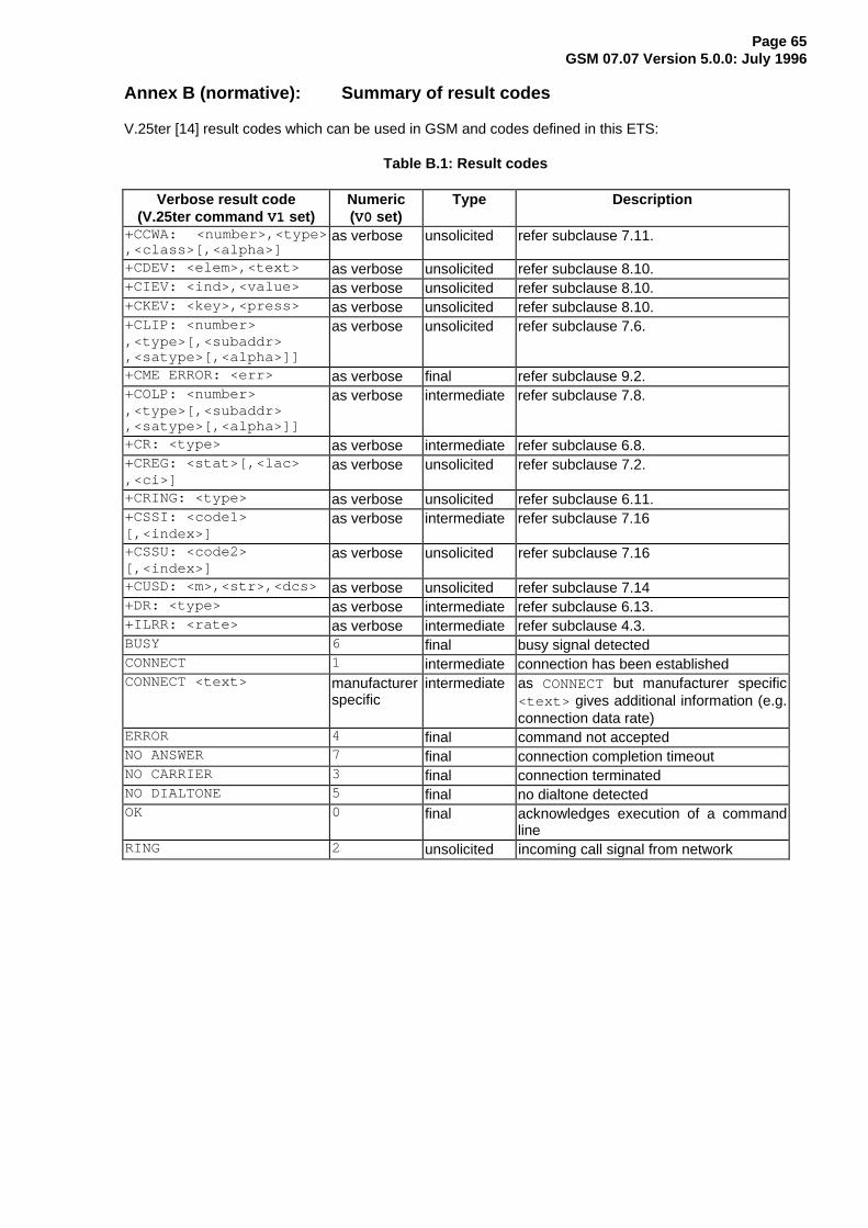
Page 65GSM 07.07 Version 5.0.0: July 1996
Annex B (normative): Summary of result codes
V.25ter [14] result codes which can be used in GSM and codes defined in this ETS:
Table B.1: Result codes
Verbose result code(V.25ter command V1 set)
Numeric(V0 set)
Type Description
+CCWA: <number>,<type>,<class>[,<alpha>]
as verbose unsolicited refer subclause 7.11.
+CDEV: <elem>,<text> as verbose unsolicited refer subclause 8.10.+CIEV: <ind>,<value> as verbose unsolicited refer subclause 8.10.+CKEV: <key>,<press> as verbose unsolicited refer subclause 8.10.+CLIP: <number>,<type>[,<subaddr>,<satype>[,<alpha>]]
as verbose unsolicited refer subclause 7.6.
+CME ERROR: <err> as verbose final refer subclause 9.2.+COLP: <number>,<type>[,<subaddr>,<satype>[,<alpha>]]
as verbose intermediate refer subclause 7.8.
+CR: <type> as verbose intermediate refer subclause 6.8.+CREG: <stat>[,<lac>,<ci>]
as verbose unsolicited refer subclause 7.2.
+CRING: <type> as verbose unsolicited refer subclause 6.11.+CSSI: <code1>[,<index>]
as verbose intermediate refer subclause 7.16
+CSSU: <code2>[,<index>]
as verbose unsolicited refer subclause 7.16
+CUSD: <m>,<str>,<dcs> as verbose unsolicited refer subclause 7.14+DR: <type> as verbose intermediate refer subclause 6.13.+ILRR: <rate> as verbose intermediate refer subclause 4.3.BUSY 6 final busy signal detectedCONNECT 1 intermediate connection has been establishedCONNECT <text> manufacturer
specificintermediate as CONNECT but manufacturer specific
<text> gives additional information (e.g.connection data rate)
ERROR 4 final command not acceptedNO ANSWER 7 final connection completion timeoutNO CARRIER 3 final connection terminatedNO DIALTONE 5 final no dialtone detectedOK 0 final acknowledges execution of a command
lineRING 2 unsolicited incoming call signal from network

Page 66GSM 07.07 Version 5.0.0: July 1996
Annex C (informative): Commands from TIA IS-101
C.1 Introduction
The "Voice Control Interim Standard for Asynchronous DCE", TIA IS-101, contains some commands thatare useful when passing audio "data" (that is, data which represents audio information) between thecomputer and the TA.
Some of the following subsections describe commands from IS-101 which are central to this TAapplication. However, with the exception of necessary extensions, these descriptions are not intended toreplace the definitions found in IS-101. Other novel commands from the interim standard are not includedbecause they are peripheral to TA operation.
NOTE: IS-101 also uses V.25ter [14] AT commands, but these are not mentioned here.
The standard specifies the following modes:
- command mode, where there is no transfer of audio "data" between the TA and the computer. Incommand mode, the computer is neither sending audio data to the TA nor receiving audio datafrom the TA.
- transmit mode, where audio "data" is being transferred from the computer to the TA. No audio"data" is transferred from the TA to the computer in this state. A transition back to command modeoccurs when an embedded command indicates "end of play" or "flush data", or an inactivity timertimes out.
- receive mode, where audio "data" is being transferred from the TA to the computer. No audio"data" is transferred from the computer to the TA in this state. A transition back to command modeoccurs when any command is sent from the computer, or an inactivity timer times out. During thereceive mode, the TA embeds result codes into the audio "data". These result codes indicatepermanent events such as "silence detected", "busy detected", and so on.
Strictly, the standard specifies another mode (translation), but this is not directly of interest here.
NOTE: The TA "knows" the type of an incoming call (whether it is voice, data, fax, whatever),and certain POTS events cannot occur. Hence some standard result codes forindication of events and discrimination of call type are unnecessary.
There are three possible levels of service:
- a TA supporting level A performs the following operations and detects the following events: audiotransmit, audio receive, DTMF detection, DTMF generation and single tone generation. Thefollowing indications are supported:
Event Description Handset state3 ring idle4 DTMF received idle5 receive buffer overrun receive6 unsolicited fax request idle8 phone on/off hook idle9 presumed hangup receive10 presumed end of message receive18 ringback idle19 busy idle23 playback buffer underrun transmit25 fax or data request acknowledged idle
- a TA supporting level B performs the operations and events of level A, and also supports DTMFdetection while in the transmit state.
- a TA supporting level C performs the operations and events of level B, and also supports doubleDTMF tone generation.

Page 67GSM 07.07 Version 5.0.0: July 1996
Since DTMF detection and generation cannot be guaranteed over current digital networks, it follows thatnone of the three levels of service can be supported.
C.2 Commands
C.2.1 Select mode +FCLASS
This command puts the TA into a particular mode of operation (data, fax, voice etc.). This causes the TAto process information in a manner suitable for that type of information (rather than for other types ofinformation). The values and meanings of parameter <n> are specified in the following table.
<n> Mode0 data1 fax class 1 (TIA-578-A)1.0 fax class 1 (ITU-T T.31 [11])2 fax (manufacturer specific)2.0 fax class 2 (ITU-T T.32 [12] and TIA-592)3...7 reserved for other fax modes8 voice9...15 reserved for other voice modes16..79 reserved80 VoiceView (Radish)81..255 reserved
Table C.1: +FCLASS
Command Return+FCLASS=<n>+FCLASS? <n>+FCLASS=? (list of supported <n>s)
Voice mode is of particular interest here, and has an additional result code +VCON. Specifically, +VCONindicates that the TA is entering the voice command mode and there is a voice connection to at least oneaudio input or output. This presupposes that some mechanism has previously initiated a connection tothat audio I/O.
C.2.2 Buffer threshold setting +VBT
This refers to integers <lo> and <hi> that indicate levels within the TA transmit buffer at which flowcontrol is asserted and deasserted. The buffer is used for averaging out the irregular timing of data fromthe computer, so that the data becomes synchronous and may be sent to some audio device.
Table C.2: +VBT
Command Return+VBT=<lo>,<hi>+VBT? <lo>,<hi>+VBT=? ( list of supported <lo> s),( list of supported <hi> s),( buffer size)

Page 68GSM 07.07 Version 5.0.0: July 1996
C.2.3 Calling number ID presentation +VCID
The command refers to an integer that allows a called party to enable or disable (<n>=0) the reporting ofthe ID of calling parties, and specifies the method of presentation of the ID. This is basically the same asGSM supplementary service CLIP (Calling Line Identification Presentation). The presentation may beeither formatted (<n>=1) or unformatted (<n>=2):
- Formatted presentation : data items are reported in the form of <tag>=<value> pairs.
<tag> <value>DATE MMDD (month, day)TIME HHMM (hour, minute)NMBR calling number or P or O (P = number is private, O = number is unavailable)NAME subscription listing nameMESG data from other (unknown) tags
- Unformatted presentation : here the data is presented in ASCII hex as printable numbers.
Table C.3: +VCID
Command Return+VCID=<n>+VCID? <n>+VCID=? (0-2)
C.2.4 Receive gain selection +VGR
This refers to the amplification by the TA of audio samples sent from the TA to the computer. Thecommand operates on an integer <n>, range 0...255. Values larger than 128 indicate a larger gain thannominal. Values less than 128 indicate a smaller gain than nominal. The entire range of 0...255 does nothave to be provided. A value of zero implies the use of automatic gain control by the TA.
Table C.4: +VGR
Command Return+VGR=<n>+VGR? <n>+VGR=? ( list of supported <n>s)
C.2.5 Transmit gain selection +VGT
This refers to the amplification by the TA of audio samples sent from the computer to the TA. Thecommand operates on an integer <n>, range 0...255. Values larger than 128 indicate a larger gain thannominal. Values less than 128 indicate a smaller gain than nominal. The entire range of 0...255 does nothave to be provided. A value of zero implies the uses of automatic gain control by the TA.
Table C.5: +VGT
Command Return+VGT=<n>+VGT? <n>+VGT=? ( list of supported <n>s)
C.2.6 Initialise voice parameters +VIP
This recalls manufacturer determined settings <n> of voice parameters. The command is write only. Theeffect of the command is manufacturer specific.

Page 69GSM 07.07 Version 5.0.0: July 1996
Table C.6: +VIP
Command Return+VIP=<n>+VIP=? ( list of supported <n>s)
C.2.7 Inactivity timer +VIT
This refers to the value of the inactivity timer in the TA. It is used to monitor activity on the connectionbetween the computer and the TA when the computer is in "transmit" mode and sending audio data to theTA. When the connection has been inactive for the time set by this command, the TA leaves "transmit"mode and reverts to command mode. An integer <n> different than zero implies a time of <n>/10seconds. A value of zero disables the timer.
Table C.7: +VIT
Command Return+VIT=<n>+VIT? <n>+VIT=? ( list of supported <n>s)
C.2.8 Line selection +VLS
This determines the selection of sources and destinations of audio samples. An integer is used to label aparticular combination of sources and destinations. The integer is defined in an entry in IS-101 whichassumes as a model a TA, a local phone and a phone line. Two additional "manufacturer specific"configurations (16,17) are defined.
- label=0: this is the idle state - the phone is not connected to the radio network and no audio pathsare used.
- label=1: the phone is connected to the radio network and no audio paths involving the internalmicrophone or internal loudspeaker are selected. This allows the computer to transmit audio dataover the radio transmitter by selecting "transmit mode":
Table C.8: +VLS label 1a
loudspeaker computer i/p transmit stagemicrophone -->computer o/p --> *receiver stage -->
This also allows the computer to receive audio data from the radio receiver by selecting "receivemode":
Table C.9: +VLS label 1b
loudspeaker computer i/p transmit stagemicrophone -->computer o/p -->receiver stage --> *
- label=4: the phone is not connected to the radio network but there is an audio path to the internalspeaker. This allows the computer to play sound by selecting "transmit mode".
Table C.10: +VLS label 4
loudspeaker computer i/p transmit stagemicrophone -->computer o/p --> *receiver stage -->

Page 70GSM 07.07 Version 5.0.0: July 1996
- label=6: the phone is not connected to the radio network but there is an audio path to the internalmicrophone. This allows the computer to record sound by selecting "receive mode".
Table C.11: +VLS label 6
loudspeaker computer i/p transmit stagemicrophone --> *computer o/p -->receiver stage -->
- label=7: the phone is connected to the radio network. The internal microphone is connected to theradio transmitter. The radio receiver is connected to the internal loudspeaker. This allows thecomputer to enable normal phone operation (a human holding a conversation) by selectingcommand mode.
Table C.12: +VLS label 7
loudspeaker computer i/p transmit stagemicrophone --> *computer o/p -->receiver stage --> *
Table C.13: +VLS
Command Return+VLS=<n> +VCON+VLS? <n>+VLS=? complex; refer IS-101
+VCON is returned if an audio path is established or if a connection is made to the radio network.
Manufacturer specific extension (reserved as such by IS-101)
- label=16: the phone is connected to the radio network. There is a path to the internal microphone,which is also connected to the radio transmitter. There is a path to the radio receiver, which is alsoconnected to the internal loudspeaker. This allows the computer to record the sum of transmittedand received audio by selecting "receive mode".
Table C.14: +VLS label 16
loudspeaker computer i/p transmit stagemicrophone --> * *computer o/p -->receiver stage --> * *
- label=17: the phone is connected to the radio system and there is a path to the internal loudspeakerand to the radio transmitter. This allows the computer to simultaneously play sound and send audioover the radio by selecting "transmit mode".
Table C.15: +VLS label 17
loudspeaker computer i/p transmit stagemicrophone -->computer o/p --> * *receiver stage -->
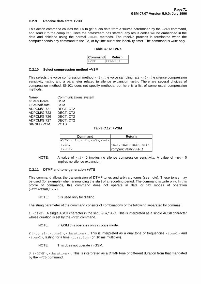
Page 71GSM 07.07 Version 5.0.0: July 1996
C.2.9 Receive data state +VRX
This action command causes the TA to get audio data from a source determined by the +VLS command,and send it to the computer. Once the datastream has started, any result codes will be embedded in thedata and shielded using the normal <DLE> methods. The receive process is terminated when thecomputer sends any command to the TA, or by time-out of the inactivity timer. The command is write only.
Table C.16: +VRX
Command Return+VRX CONNECT
C.2.10 Select compression method +VSM
This selects the voice compression method <n1> , the voice sampling rate <n2> , the silence compressionsensitivity <n3> , and a parameter related to silence expansion <n4> . There are several choices ofcompression method. IS-101 does not specify methods, but here is a list of some usual compressionmethods:
Name Communications systemGSM/full-rate GSMGSM/half-rate GSMADPCM/G.721 DECT, CT2ADPCM/G.723 DECT, CT2ADPCM/G.726 DECT, CT2ADPCM/G.727 DECT, CT2SIGNED PCM POTS
Table C.17: +VSM
Command Return+VSM=<n1>,<n2>,<n3>,<n4>+VSM? <n1>,<n2>,<n3>,<n4>+VSM=? complex; refer IS-101
NOTE: A value of <n3>=0 implies no silence compression sensitivity. A value of <n4>=0implies no silence expansion.
C.2.11 DTMF and tone generation +VTS
This command allows the transmission of DTMF tones and arbitrary tones (see note). These tones maybe used (for example) when announcing the start of a recording period. The command is write only. In thisprofile of commands, this command does not operate in data or fax modes of operation(+FCLASS=0,1,2-7).
NOTE: D is used only for dialling.
The string parameter of the command consists of combinations of the following separated by commas:
1. <DTMF>. A single ASCII character in the set 0-9, #,*,A-D. This is interpreted as a single ACSII characterwhose duration is set by the +VTD command.
NOTE: In GSM this operates only in voice mode.
2. [<tone1>,<tone2>,<duration>] . This is interpreted as a dual tone of frequencies <tone1> and<tone2> , lasting for a time <duration> (in 10 ms multiples).
NOTE: This does not operate in GSM.
3. {<DTMF>,<duration>} . This is interpreted as a DTMF tone of different duration from that mandatedby the +VTD command.
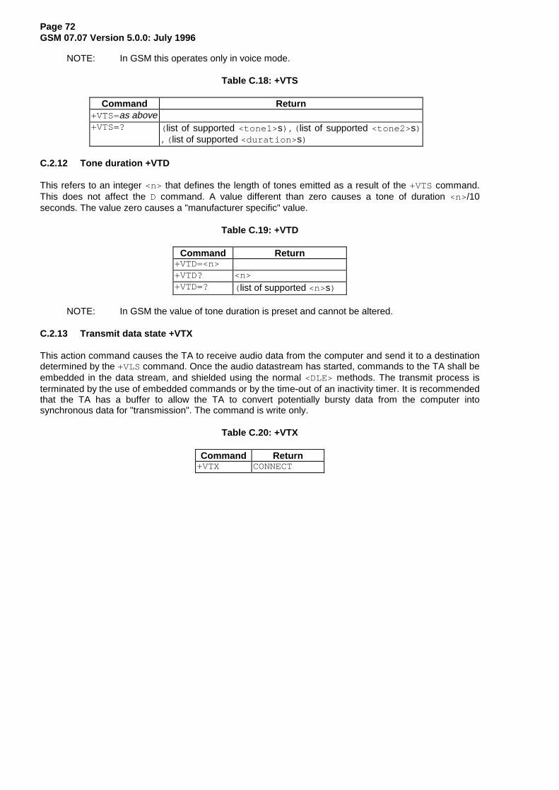
Page 72GSM 07.07 Version 5.0.0: July 1996
NOTE: In GSM this operates only in voice mode.
Table C.18: +VTS
Command Return+VTS=as above+VTS=? ( list of supported <tone1> s),( list of supported <tone2> s)
,( list of supported <duration> s)
C.2.12 Tone duration +VTD
This refers to an integer <n> that defines the length of tones emitted as a result of the +VTS command.This does not affect the D command. A value different than zero causes a tone of duration <n>/10seconds. The value zero causes a "manufacturer specific" value.
Table C.19: +VTD
Command Return+VTD=<n>+VTD? <n>+VTD=? ( list of supported <n>s)
NOTE: In GSM the value of tone duration is preset and cannot be altered.
C.2.13 Transmit data state +VTX
This action command causes the TA to receive audio data from the computer and send it to a destinationdetermined by the +VLS command. Once the audio datastream has started, commands to the TA shall beembedded in the data stream, and shielded using the normal <DLE> methods. The transmit process isterminated by the use of embedded commands or by the time-out of an inactivity timer. It is recommendedthat the TA has a buffer to allow the TA to convert potentially bursty data from the computer intosynchronous data for "transmission". The command is write only.
Table C.20: +VTX
Command Return+VTX CONNECT

Page 73GSM 07.07 Version 5.0.0: July 1996
Annex D (informative): Bibliography
Informative references:
1) IrDA Serial Infrared Physical Layer Specification
IrDA Serial Infrared MAC and Link Protocol
IrDA Serial Infrared Link Access Protocol
2) PCCA XANX-101-I Data Transmission Systems and Equipment - SerialAsynchronous Automatic Dialling and Control for Character Mode DCE onWireless Data Services - Annex I: Command Extensions for Analog CellularData Modems
3) TIA IS-101 Facsimile Digital Interfaces - Voice Control Interim Standard forAsynchronous DCE
4) TIA-578-A Facsimile Digital Interfaces - Asynchronous Facsimile DCE ControlStandard, Service Class 1
5) TIA-592 Facsimile Digital Interfaces - Asynchronous Facsimile DCE ControlStandard, Service Class 2
6) TIA-617 Data Transmission Systems and Equipment - In-Band DCE Control

Page 74GSM 07.07 Version 5.0.0: July 1996
Annex E (informative): Mobile originated alternating voice/data call example
Figure E.1 illustrates the possible transitions in MO BS 61 call. Responses and result codes generated byTA are in bold face. In this example, data part of the call is asynchronous non-transparent 9600 bpsservice.
VOICE
ATD (or ATA)
remote initiatedin-call modificationsuccessful
ATH(or AT+CHUP or drop DTR)
remotehangup
DATA
ATH (or drop DTR)
remote initiatedin-call modificationsuccessful
AT+CHUPremotehangup
(V.24 circuit 109 ON)
OFF-LINE
TA sets +CMOD=0
AT+CBST=7,0,1OKAT+COLP=1; +CR=1; +DR=1; +ILRR=1OKAT+CMOD=2; +FCLASS=0OK
OFF-LINE
ATD12345; ATD12345
success+COLP: +35812345,145+CR: REL ASYNC+DR: NONE+ILRR: 19200OK
success+COLP: +35812345,145+CR: REL ASYNC+DR: NONE+ILRR: 19200CONNECT 19200
RLP negotiation failure+COLP: +35812345,145+CR: REL ASYNCNO CARRIER
connection failureNO CARRIERAT+CEER+CEER: failure causeOKremote busyBUSYremote does not answerNO ANSWERgeneral failureERROR
in-call modification successCONNECT 9600
in-call modification failureERRORAT+CEER+CEER: failure causeOK
in-call modification failureERRORAT+CEER+CEER: failure causeOK
CONNECT 9600
in-call modification successOK
OK
OK OK
NO CARRIERNO CARRIER
Figure E.1: MO BS 61 call

Page 75GSM 07.07 Version 5.0.0: July 1996
Annex F (informative): Mobile terminated voice followed by data call example
Figure F.1 illustrates the possible transitions in MT BS 81 call. Responses and result codes generated byTA are in bold face. In this example, data part of the call is asynchronous non-transparent 9600 bpsservice.
VOICE
ATD (or ATA)
remote initiatedin-call modificationsuccessful
ATH(or AT+CHUP or drop DTR)
remotehangup
DATA
remotehangup
(V.24 circuit 109 ON)
OFF-LINE
TA sets +CMOD=0
AT+CLIP=1; +CR=1; +DR=1; +ILRR=1; +CRC=1OK
+CRING: VOICE/REL ASYNC
+CLIP: +35812345,145
AT+CMOD=3; +FCLASS=0; A
OFF-LINE
success+CR: REL ASYNC+DR: NONE+ILRR: 19200OK
connection failureNO CARRIERAT+CEER+CEER: failure causeOKgeneral failureERROR
in-call modification successCONNECT 9600
in-call modification failureERRORAT+CEER+CEER: failure causeOK
CONNECT 9600
ATH(or AT+CHUP or drop DTR)
OK OK
NO CARRIERNO CARRIER
Figure F.1: MT BS 81 call

Page 76GSM 07.07 Version 5.0.0: July 1996
Annex G (informative): Voice call example
Figure G.1 illustrates the possible transitions in both MT and MO TS 11 calls. Responses and result codesgenerated by TA are in bold face.
VOICE call active
ATH(or AT+CHUP or drop DTR)
remotehangup
AT+CLIP=1; +CRC=1OK
+CRING: VOICE
+CLIP: +35812345,145
ATA
MT
successOK
connection failureNO CARRIERAT+CEER+CEER: failure causeOKremote busyBUSYgeneral failureERROR
OKNO CARRIER
AT+COLP=1OKATD12345;
MO with COLP
AT+COLP=0OKATD12345;
MO without COLP
connection failureNO CARRIERAT+CEER+CEER: failure causeOK
success+COLP: +35812345,145OK
(remote ring orother networkgenerated tones)
general failureERROR
call setup started OK
connection failureNO CARRIERAT+CEER+CEER: failure causeOK
(no indicationon successfulcall setup)
Figure G.1: TS 11 calls

Page 77GSM 07.07 Version 5.0.0: July 1996
History
Document history
July 1996 Publication of version 5.0.0
ISBN 2-7437-0826-3Dépôt légal : Juillet 1996


![U10 Hardware Design V1 - Quectel Wireless Solutions3] 3GPP TS 27.007 (GSM 07.07) AT command set for User Equipment (UE) [4] 3GPP TS 27.060 (GSM 07.60) Mobile Station (MS) supporting](https://static.fdocuments.in/doc/165x107/5ebf7fd75218c92d632a0c6f/u10-hardware-design-v1-quectel-wireless-solutions-3-3gpp-ts-27007-gsm-0707.jpg)