GSE Model 675 - scale service€¦ · · 2018-03-044 CHAPTER 2: CONFIGURATION The GSE 675...
48
GSE Model 675 Precision Counting Scale USERS GUIDE Version 2.0
-
Upload
vuongnguyet -
Category
Documents
-
view
214 -
download
0
Transcript of GSE Model 675 - scale service€¦ · · 2018-03-044 CHAPTER 2: CONFIGURATION The GSE 675...
GSE Model 675 Precision Counting Scale
USERS GUIDE Version 2.0


Model 675
USERS GUIDE Version 2.0

GSE 675 Precision Parts Counter Quick Reference Guide Copyright © 2004 GSE Scale Systems. All rights reserved. Published by: GSE Scale Systems 42860 Nine Mile Road Novi, MI 48375 USA Information in this Users Guide is subject to change without notice due to correction or enhancement. The information described in this manual is solely the property of GSE. No part of this manual may be reproduced or transmitted in any form or by any means, electronic or mechanical, including photocopying and recording and sold for any monetary figure without the express written permission of GSE.
GSE Locations
GSE Scale Systems 42860 Nine Mile Road Novi, MI 48375 U.S.A. Phone: (800) 755-7875 www.gse-inc.com
GSE Canada, Inc. 617 East Lake Road Airdrie, Alberta Canada T4B 2B8 Phone:(403) 948-9921 Fax: (403) 948-1449

i
TABLE OF CONTENTS
CHAPTER 1: REFERENCE........................................................................................... 1 KEYPAD FUNCTIONS ........................................................................................................ 1 BACK PANEL CONNECTIONS ............................................................................................ 2
CHAPTER 2: CONFIGURATION................................................................................. 4 F1 SOFT KEY- QUICK COUNT .......................................................................................... 4 F2 SOFT KEY- GSE CUSTOM........................................................................................... 5
Apw Lookup ................................................................................................................ 5 F3 SOFT KEY- GSE DEFAULT ......................................................................................... 6 QUICK COUNT CONFIGURATION SETUP MENU ................................................................ 7
Setup............................................................................................................................ 7 Setup Menus ................................................................................................................ 8 CAL (Calibration)....................................................................................................... 8 Display Style ............................................................................................................... 8 Preset Printouts .......................................................................................................... 9
APW LOOKUP CONFIGURATION SETUP MENU .............................................................. 10 Setup.......................................................................................................................... 11 Setup Menus .............................................................................................................. 11 CAL (Calibration)..................................................................................................... 11 Display Style ............................................................................................................. 12 Print Menu ................................................................................................................ 13 Preset Printouts ........................................................................................................ 14 Advanced Setup Menu............................................................................................... 15 Time/Date.................................................................................................................. 16 Setup Mode Access (Setup) ....................................................................................... 16
CHAPTER 3: OPERATION ......................................................................................... 17 QUICK COUNT................................................................................................................ 17
Without Auto Tare ................................................................................................ 18 APW LOOKUP ............................................................................................................... 19
Sample and Count ..................................................................................................... 19 Without Auto Tare ................................................................................................ 19
Store a New Part Number ......................................................................................... 20 Update a Part Number.............................................................................................. 20 Recall a Part Number ............................................................................................... 20 Delete a Part Number ............................................................................................... 21
SIMPLE KEYPAD SAMPLE............................................................................................... 21 Without Auto Tare ................................................................................................ 22
CHAPTER 4: CALIBRATION..................................................................................... 23
CALIBRATION METHODS................................................................................................ 23 General Notes on Calibration................................................................................... 23
New Zero .............................................................................................................. 24

ii
Last Zero ............................................................................................................... 25 Temporary Zero .................................................................................................... 26 Only Zero .............................................................................................................. 27 Calibration Reset................................................................................................... 27 Known Loadcell Output........................................................................................ 28 Multi - Scale Calibration....................................................................................... 29
CHAPTER 5: LEGAL FOR TRADE ........................................................................... 30 NTEP REQUIREMENTS .................................................................................................. 30
NTEP Custom Setup.................................................................................................. 31 Accessing the Custom Setup List ......................................................................... 31 Custom Setup Parameters ..................................................................................... 31 Additional Conformance Considerations.............................................................. 32
SEALING AND AUDIT TRAILS......................................................................................... 32 Physical Seal............................................................................................................. 33 Audit Trails ............................................................................................................... 33
OIML Audit Trail ................................................................................................. 34 Calibration Audit Trail.......................................................................................... 34 Setup Audit Trail................................................................................................... 34 Viewing Audit Trail Parameters ........................................................................... 34
OMIL REQUIREMENTS .................................................................................................. 34 Enabling OIML Operation.................................................................................... 35
OTHER REQUIREMENTS.................................................................................................. 35
CHAPTER 6: TROUBLESHOOTING ........................................................................ 36 OPERATIONAL ERRORS .................................................................................................. 36 SETUP MODE ERRORS.................................................................................................... 36 HARDWARE ERRORS ...................................................................................................... 37 CALIBRATION ERRORS................................................................................................... 38 COMMUNICATION ERRORS............................................................................................. 38

iii

1
CHAPTER 1: REFERENCE This chapter describes the function of the keypad. Also tables show the connections for the second scale and comm ports.
Keypad Functions All of the keys perform different functions. Some keys have more than one function.
Act as soft keys which will perform a specific function. Refer to the text on the display for the function of each soft key.
Subtracts the weight of the tare from the displayed weight. Commonly used for removing the weight of a container.
Performs a gross zero and displays the gross mode.
Performs a sample for an accurate parts counting and calculates an average piece weight.
Toggles the units of measure between lb, kg, g, ounce, etc.
Selects between all enabled scales. Will display current scale number.
Print data from a specified communication port.
Select among modes such as Gross, Net, Tare, Quantity and Average Piece Weight.
Clear the entry buffer or answer “NO” to a question.

2
Enter data or answer “YES” to a question.
Enter alpha or numeric characters or a combination of both depending on the ALPHA key parameter configuration..
Turn the scale on or off.
- , Numeric keys used to manually enter a value for tare weight, average piece weight, sample size etc.
Back Panel Connections Connections for a second scale, Com1 and Com 2 ports are standard with the Model 675. Connector pin outs are provided in the tables below. Refer to Table 2 below for the pin of Com 3 and Com 4 ports (optional). Table 1: Scale 2 DB 9 Connector Pin Out
If a load cell with a 4 wire cable is being used jumpers will need to be installed between the sense and excitation. The jumpers will be installed on the DB9 connector being installed on the load cell cable. Refer to Table 1 for pin number designation.
DB9 pin designation Function Load Cell Cable 1 + Signal 4 or 6 wire 2 - Signal 4 or 6 wire 3 + Sense 4 wire (connect a wire jumper to pin 8) 4 - Sense 4 wire (connect a wire jumper to pin 9) 5 - Excitation 4 or 6 wire 6 + Excitation 4 or 6 wire 7 Chassis Ground 4 or 6 wire 8 + Excitation 4 wire (connect a wire jumper to pin 3) 9 - Excitation 4 wire (connect a wire jumper to pin 4)

3
Table 2: Communication Ports 1 -4 Pin Out
DB9 pin designation
Function Com 1
Function Com 2
Function Com 3
Function Com 4
1 No connection TTL No connection No connection 2 RXD RXD RXD RXD 3 TXD TXD TXD TXD 4 + 5V + 5V + 5V + 5V 5 ISO Ground Ground Ground Ground 6 Ground Ground Ground Ground 7 RTS RTS No connection No connection 8 CTS CTS CTS No connection 9 Remote Key 1 Remote Key 2 No connection No connection

4
CHAPTER 2: CONFIGURATION The GSE 675 Precision Counting Scale comes from the factory with the Application Menu enabled. This is where you will choose the preferred method of parts counting. See the explanations of each method below. After each counting method are the instructions for setting up that method.
Refer to Chapter 3: Operation for operating instructions of each method.
Figure 1: Counting Method Choices
F1 Soft Key- Quick Count The QUICK COUNT mode is designed for performing a quick sample and count. The soft keys are used in secession from left to right to increase speed and ease of parts counting. Basic functionality is offered to simplify operation. Below are the available soft keys and an explanation of their purpose in the QUICK COUNT mode.
Sample – Uses default sample size and prompts user to add that many pieces
Count – Gives access to the quantity mode.
Accum (accumulate) – Maintains a total of quantity accumulations. The current quantity is added to this total each time an accumulation is done.
Print – Send specific information to a printer, computer or other peripheral devices.
Setup – Access setup menus, see page 7 for further details.
F1
F2
F5
F3
F4

5
Setup the QUICK COUNT Mode
1. Press from the APPLICATION MENU. The display will come up with an explanation of the QUICK COUNT menu.
2. At this time you can choose the QUICK COUNT mode by pressing the
(YES) or return to the APPLICATION MENU by pressing the softkey
(Exit) or (NO).
3. The QUICK COUNT file will load automatically and return to the QUICK COUNT mode.
F2 Soft Key- GSE Custom Presently APW LOOKUP is the only application offered under GSE Custom. New modes will be added in the near future. Please check out the GSE website gse-inc.com for new updates.
The APW LOOKUP offers the flexibility of storing and recalling part numbers. The average piece weight and part description will be stored and recalled with the part number.
APW LOOKUP Sample - Uses default sample size and prompts user to add that many pieces.
Store – Store a part number with average piece weight and description.
Rec/New – Add a new part number or recall a part number from the database.
Desc – Add a part description.
Setup - Access setup menus, see page 10 for further details.
F2
F4
F5
F3
F1

6
Setup the APW LOOKUP Mode
1. Press the from the APPLICATION MENU. The display will come up with an explanation of the APW LOOKUP menu.
2. At this time you can choose the APW LOOKUP mode by pressing the
(YES) or return to the menu choices by pressing the softkey (Exit) or (NO).
3. The APW LOOKUP file will load and will return to the APW LOOKUP mode.
F3 Soft Key- GSE Default If the preprogrammed applications are not going to be used, than the Model 675 should be factory defaulted. This mode will reset the Model 675 to GSE factory default status. The preset applications will be lost but can be reestablished at parameter 65002 (See technical reference manual for more details).
The Model 675 can still be used as a parts counter after it is factory defaulted. Refer to page 21 for more details on simple counting.
Setup the GSE DEFAULT Mode 1. Press from the APPLICATION MENU prompt. The display will give an
explanation of the GSE DEFAULT.
2. Press (YES) to accept the choice of GSE DEFAULT and continue or press
to cancel the default and return to the APPLICATION MENU.
3. If you chose to continue with the default in step 2 the display will ask ARE YOU
SURE? Either press (YES) to default the unit or press to cancel the default and return to the APPLICATION MENU.

7
Quick Count Configuration Setup Menu Use the F5 Setup key from the QUICK COUNT screen to gain access to different menus.
SETUP This menu was designed for accessing the items that will need to be changed the most often. Below is an explanation of the choices in the menu. Follow the instructions on the display for each key.
PARAMETER DESCRIPTION DEFAULT SETTING KEYPRESSES
CHANGE SAMPLE
Change the default sample size
10 Key in new sample size and press Enter to accept or F5 to escape
CLEAR TOTALS
Clears the accumulation registers
Not applicable Press Enter to clear totals or Clr to escape
KEY-IN APW Key in an average piece weight for sample
0 Key in new average piece weight and press Enter or F5 to escape
SETUP MENUS Continues on to the Setup Menus
Not applicable
Change Sample
Clear Totals
Key-In APW
Setup Menus
Exit
F1 F2 F3 F4 F5
Cal Display Style
Print Formats
Advance Setup
Exit
F1 F2 F3 F4 F5
See page 15 for complete details on the Advanced Setup Menu.
The YES key is the NO key is .
Setup F5

8
SETUP MENUS This is the next level of menus, which offer more advanced setup.
PARAMETER DESCRIPTION DEFAULT SETTING KEYPRESSES
CAL Calibration any of the enabled scales
Not applicable Key in access code and press Enter or press F5 to escape
DISPLAY STYLE
Chose how the display will appear
Display Style 2 Press either F1 or F2 to chose the desired display style or F5 to escape
PRINT FORMATS
Chose a preformatted printout
Print Style 1 Use F3 and F4 to view print format choices. Press F5 to save the format
ADVANCE SETUP
Continues on to the Advanced Setup Menu
Not applicable See page 15
CAL (CALIBRATION) Refer to Chapter 4: Calibration on page 23 for complete instructions on calibrating the Model 675.
DISPLAY STYLE Choose one of the display types and press (EXIT) to save the change and return to the main menu. STYLE 1 – This is the classic GSE 2x5 display. The weight or quantity will be displayed in larger font while the prompts will be to the right of the weight display. STYLE 2 – This style incorporates the classic GSE 2x5 display along with two smaller
displays which will show other parameters. Press the key from the QUICK COUNT to toggle through the different parameter choices.
Large display Small Display Small Display Gross Net Tare Quantity Net Tare Quantity Net Piece Weight Quantity Tare Piece Weight Quantity Accuracy Piece Weight Quantity Accuracy Sample Size Quantity Sample Size Piece Weight Quantity Quantity Total Number of Accums

9
PRESET PRINTOUTS The preset print formats are viewable on the LCD display. Use the left arrow and
right arrow keys to view all transmit styles. Chose the desired format by viewing it
on the screen. Press the (EXIT) key to save the format and return to the main menu. Choice 1 Choice 2
Choice 3 Choice 4
Choice 5 Choice 6
Choice 7
Quantity: 30 APW: 0.1234 Tare: 1.515 lb
Quantity: 30 APW: 0.1234 Tare: 1.515 10:10:00 07/10/2003
Quantity: 30 Tare: 1.515 Scale # 2
Part#: Quantity 55 APW 0.4481 Tare 1.623
10.025 lb Gross 2.500 lb Tare 7.525 lb Net
Quantity: 55 QTY Total: 510 Total Accums: 10
Part#: Quantity 55 APW 0.4481 Tare 1.623 10:10:00 07/10/2003

10
APW Lookup Configuration Setup Menu Use the F5 Setup key from the APW LOOKUP screen to gain access to different menus.
Change Sample
Delete Part#
Key-In APW
Setup Menus
Exit
F1 F2 F3 F4 F5
Cal Display Style
Print Menu
Advance Setup
Exit
F1 F2 F3 F4 F5
Print Part#s
D-Load Part#s
Print Formats
Exit
F1 F2 F3 F4 F5
See page 15 for complete details.
Comm 1
Comm 2
Display Exit
F1 F2 F3 F4 F5
Comm 1
Comm 2
Exit
F1 F2 F3 F4 F5
SetupF5

11
SETUP This menu was designed for accessing the items that will need to be changed the most often. Below is an explanation of the choices in the menu. Follow the instructions on the display for each key.
PARAMETER DESCRIPTION DEFAULT SETTING KEYPRESSES
CHANGE SAMPLE
Change the default sample size
10 Key in new sample size and press Enter to accept or F5 to escape
DELETE PART #
Delete specified part number
Will not show until a part number is established
Key in part # and press F3. Press F5 to enter the setup. Press F2 to delete part #.
KEY-IN APW Key in an average piece weight for sample
0 Key in new average piece weight and press Enter or F5 to escape
SETUP MENUS Continues on to the Setup Menus
Not applicable Press F4 to continue
SETUP MENUS This is the next level of menus, which offer more advanced setup.
PARAMETER DESCRIPTION DEFAULT SETTING KEYPRESSES
CAL Calibration any of the enabled scales
Not applicable Key in access code and press Enter or press F5 to escape
DISPLAY STYLE
Chose how the display will appear
Style 2 Press either F1 – F4 to chose the desired display style or F5 to escape
PRINT MENU Choose what information to print out
Not applicable Continues on to the Print Menu selections
ADVANCE SETUP
Continues on to the Advanced Setup Menu
Not applicable See page 15
CAL (CALIBRATION) Refer to Chapter 4: Calibration on page 23 for complete instructions on calibrating the Model 675.
The YES key is the NO key is .
12
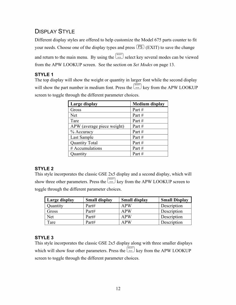
DISPLAY STYLE Different display styles are offered to help customize the Model 675 parts counter to fit
your needs. Choose one of the display types and press (EXIT) to save the change
and return to the main menu. By using the select key several modes can be viewed from the APW LOOKUP screen. See the section on Set Modes on page 13.
STYLE 1 The top display will show the weight or quantity in larger font while the second display
will show the part number in medium font. Press the key from the APW LOOKUP screen to toggle through the different parameter choices.
STYLE 2 This style incorporates the classic GSE 2x5 display and a second display, which will
show three other parameters. Press the key from the APW LOOKUP screen to toggle through the different parameter choices.
STYLE 3 This style incorporates the classic GSE 2x5 display along with three smaller displays
which will show four other parameters. Press the key from the APW LOOKUP screen to toggle through the different parameter choices.
Large display Medium display Gross Part # Net Part # Tare Part # APW (average piece weight) Part # % Accuracy Part # Last Sample Part # Quantity Total Part # # Accumulations Part # Quantity Part #
Large display Small display Small display Small Display Quantity Part# APW Description Gross Part# APW Description Net Part# APW Description Tare Part# APW Description
13
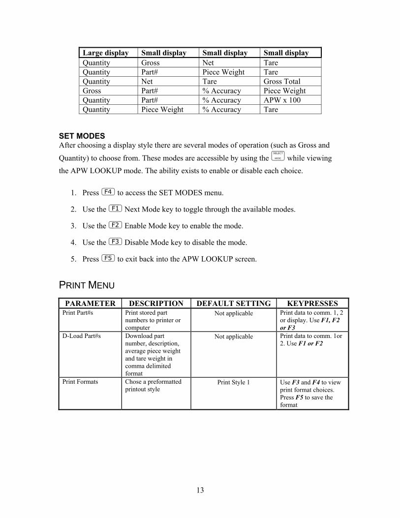
SET MODES After choosing a display style there are several modes of operation (such as Gross and
Quantity) to choose from. These modes are accessible by using the while viewing the APW LOOKUP mode. The ability exists to enable or disable each choice.
1. Press to access the SET MODES menu.
2. Use the Next Mode key to toggle through the available modes.
3. Use the Enable Mode key to enable the mode.
4. Use the Disable Mode key to disable the mode.
5. Press to exit back into the APW LOOKUP screen.
PRINT MENU
Large display Small display Small display Small display Quantity Gross Net Tare Quantity Part# Piece Weight Tare Quantity Net Tare Gross Total Gross Part# % Accuracy Piece Weight Quantity Part# % Accuracy APW x 100 Quantity Piece Weight % Accuracy Tare
PARAMETER DESCRIPTION DEFAULT SETTING KEYPRESSES Print Part#s Print stored part
numbers to printer or computer
Not applicable Print data to comm. 1, 2 or display. Use F1, F2 or F3
D-Load Part#s Download part number, description, average piece weight and tare weight in comma delimited format
Not applicable Print data to comm. 1or 2. Use F1 or F2
Print Formats Chose a preformatted printout style
Print Style 1 Use F3 and F4 to view print format choices. Press F5 to save the format

14
PRESET PRINTOUTS The preset print formats are viewable on the LCD display. Use the left arrow and
right arrow keys to view all transmit styles. Chose the desired format by viewing it
on the screen. Press the (EXIT) key to save the format and return to the main menu. Print# 1 Print# 2
Print# 3 Print# 4
Print# 5 Print# 6
Print# 7 Print# 8
P/N: ABCD123WXYZ Qty: 30
P/N: ABCD123WXYZ Qty: 30 Tare: 1.02 lb 10:10:00 09/13/2003
P/N: ABCD123WXYZ Qty: 30 Tare: 1.515 lb 10:10:00 09/13/2003
P/N: ABCD123WXYZ Qty: 30 APW: 0.0123456 Tare: 1.515 lb 10:10:00 09/13/2003
P/N: ABCD123WXYZ Qty: 30 APW: 0.0123456 Gross 26.456 lb Tare: 1.515 lb Net: 24.941 lb 10:10:00 09/13/2003
Quantity: 55 #3 Tot: 165
P/N: ABCD123WXYZ Desc: Red Cable Ties APW: 0.0123456 Sc#:1 Sampled 2 %Accy 98.555 10:10:00 09/13/2003
P/N: ABCD123WXYZ Desc: Red Cable Ties Qty: 30 10:10:00 09/13/2003

15
Print# 9
Custom
ADVANCED SETUP MENU The advanced menu will allow access to the time/date, setup mode and application files. Use the arrow keys to navigate to the desired tab. This is common on the preprogrammed methods of counting such as QUICK COUNT and APW LOOKUP.
Figure 2: Advanced Setup Menu
Reserved for future use.
CREATE A CUSTOM TRANSMIT FORMAT!
See the Tech Manual for details
Create and load as transmit #130
Your custom transmit will appear in place of this instruction tab.

16
TIME/DATE 1. From the time/date tab, press to access the configuration screen. The time
can be changed with the key. The date can be changed with the key.
2. Key in the time or date by following the format on the display and press to accept the entry.
3. Press (EXIT) to return to the main menu.
SETUP MODE ACCESS (SETUP) This tab allows access to the setup mode to make changes to parameters such as full scale, count accuracy and baud rate etc. Please refer to the 675 Series Technical Reference Manual for details on more advanced setups and configurations. An access code is required to enter the Model 675 setup mode.

17
CHAPTER 3: OPERATION This chapter will give detailed operation instructions on how to use each preprogrammed mode.
The Model 675 is designed to operate from the 5 soft keys or the dedicated keys of the keypad. The advantage of using the soft keys is they are placed in succession for easy operation.
Quick Count Auto Tare Method 1. Sampling Pieces:
(a) If a container is used: (i) Place an empty container on scale and press the Sample or
key. The scale will automatically tare the container. - or -
(b) If a container is not used:
(i) Press the Sample or key without the sample pieces on the scale. The scale will tare to establish a net zero reference.
2. Add the sample pieces and press the Accept key to accept the sample.
3. Continue to add pieces to count.
4. Press to accumulate the current quantity to the total quantity.
5. Press to print to a computer, printer or another peripheral device.
TIP Bypass the GSE splash screen on power up by pressing the key when the splash screen appears.

18
Without Auto Tare 1. Sampling pieces:
(a) If the sample size is known and a container is used:
(i) Place an empty container on the scale and press key.
(ii) Place the sample in the container.
(iii) Key in the sample size and then press the Sample or key. The scale will accept the current weights as a sample and will display the quantity.
-or-
(b) If the sample size is known and no container is used: (i) Place the sample on the scale.
(ii) Key in the sample size and then press the Sample or key. The scale will accept the current weights as a sample and will display the quantity.
Example: or
After accumulating, the weight must return to zero before another accumulation will be added. The display will show CLEAR WGHT! if the weight is not within the zero threshold. Remove weight and try again. This feature is necessary to avoid double accumulations.
Use the key to check other modes such as the Tare weight and Average Piece
Weight. The (Count) can be pressed to return to the count mode at any time.

19
APW Lookup Follow the steps below to perform a sample and count parts.
SAMPLE AND COUNT Auto Tare Method
1. Sampling Pieces:
(a) If a container is used: (i) Place container on scale and press the Sample or key.
The scale will automatically tare the container. - or -
(b) If a container is not used: (i) Press the Sample or key without the sample pieces on the
scale. The scale will tare to establish a net zero reference.
2. Add the sample pieces and press the Accept key to accept the sample.
3. Continue to add pieces to count.
Without Auto Tare
1) If the sample size is known and a container is used:
a. Place an empty container on the scale and press key.
b. Place the sample in the container.
c. Key in the sample size and then press the Sample or key. The scale will accept the current weights as a sample and will display the quantity.
-or-

20
1) If the sample size is known and no container is used: a. Place the sample on the scale.
b. Key in the sample size and then press the Sample or key. The scale will accept the current weights as a sample and will display the quantity.
Example: or
STORE A NEW PART NUMBER Part numbers can be stored in a database and can be recalled later with necessary data such as the average piece weight and description.
1. Key in the new part number and press the (Rec/New) key. The other data fields will be cleared.
2. Follow the directions for sample and count above.
3. If you want to add a part description key in the description and press (Desc.). Skip this step if the description is not necessary.
4. Press to store the part number, APW, and description.
UPDATE A PART NUMBER It is possible to update the data that is stored with a part number.
1. While viewing the part number and data press (Store). The data will be updated in the database.
RECALL A PART NUMBER A part number that was stored previously can be recalled to count parts without having to sample the part.
1. Key in the part number to recall and press (Rec/New). 2. Place pieces on the platform to count.
21
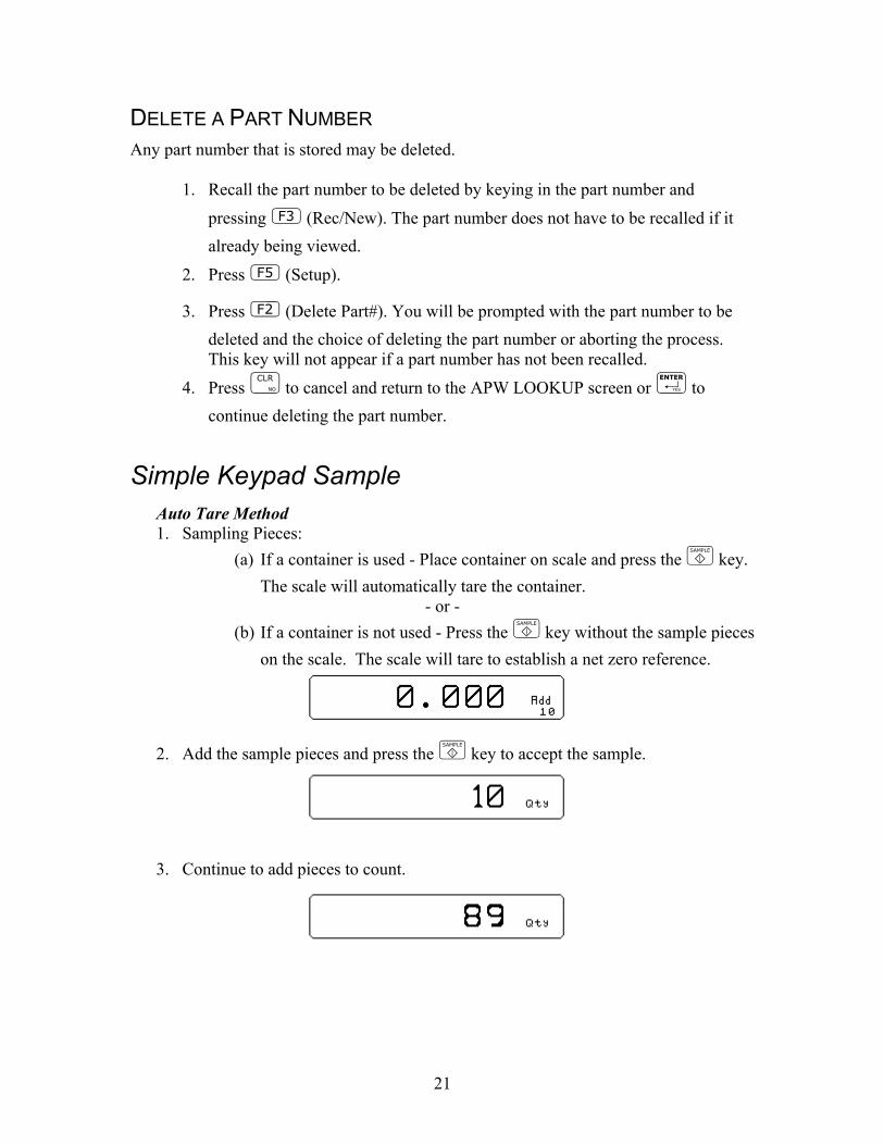
DELETE A PART NUMBER Any part number that is stored may be deleted.
1. Recall the part number to be deleted by keying in the part number and
pressing (Rec/New). The part number does not have to be recalled if it already being viewed.
2. Press (Setup).
3. Press (Delete Part#). You will be prompted with the part number to be deleted and the choice of deleting the part number or aborting the process. This key will not appear if a part number has not been recalled.
4. Press to cancel and return to the APW LOOKUP screen or to continue deleting the part number.
Simple Keypad Sample Auto Tare Method 1. Sampling Pieces:
(a) If a container is used - Place container on scale and press the key. The scale will automatically tare the container.
- or - (b) If a container is not used - Press the key without the sample pieces
on the scale. The scale will tare to establish a net zero reference.
2. Add the sample pieces and press the key to accept the sample.
3. Continue to add pieces to count.

22
Without Auto Tare
1) If the sample size is known and a container is used:
a. Place an empty container on the scale and press key.
b. Place the sample in the container.
c. Key in the sample size and then press the key. The scale will accept the current weights as a sample and will display the quantity.
-or-
1) If the sample size is known and no container is used: a. Place the sample on the scale.
b. Key in the sample size and then press the key. The scale will accept the current weights as a sample and will display the quantity.
Example:

23
CHAPTER 4: CALIBRATION The calibration mode is accessible through the configuration menu or from the weigh mode. Access Calibration from the configuration menu
1. From the main menu press the (Setup) key.
2. Press (Setup Menus) key.
3. Press (CAL) key.
4. Enter the access code and press
Calibration Methods There are six methods of calibration. Press to select a calibration method. Press to begin the calibration method selected. Refer to the appropriate section for calibration instructions.
• New Zero - Establishes a new zero (no load) and span (test load) calibration reference.
• Last Zero - Performs a span re-calibration without removing the test load. (This selection is not available with linearization enabled.)
• Temp Zero - Performs a calibration without removing the current gross weight. The zero reference determined during the last calibration is maintained. (This selection is not available with linearization enabled.)
• Only Zero - Establishes a new zero reference without affecting span.
• Cal Reset - Adjusts the zero and gain factors of the A/D amplifier to default values for maximum sensitivity.
• Known LCOut - Calibrates without the use of test weights. The mV/V value and full scale capacity of each load cell must be known.
GENERAL NOTES ON CALIBRATION
• Pressing at any point in the calibration routine moves back one step.
• Pressing at the New Zero? prompt exits calibration mode.

24
• A calibration weight can be applied before or after entering the calibration weight value. The display prompts you to Keyin CalWt (key in calibration weight) or Add CalWT (add calibration weight) at the appropriate time.
• The digital filter is automatically set to 4 seconds during calibration.
• A motion delay is enforced during zero and span calibration.
• New calibration values are not permanently saved until the calibration mode is exited and changes are saved by pressing at the ENTER=SAVE prompt. If power is lost during calibration, the previously saved calibration values will be in effect when power is restored.
• If replacing one indicator with another, it is possible to set the total gain value (P61108) of the new indicator with that of the original. This will optimize the coarse and fine gain values, greatly increasing the likelihood of a successful calibration on the first attempt.
New Zero The most common calibration procedure, New Zero establishes a new zero (no load) and span (test load) calibration reference. Use this method for first-time calibration and complete re-calibration.
TO PERFORM A NEW ZERO CALIBRATION: 1. Remove all weight from the scale. 2. Enter calibration as described on page 23. 3. Select the New Zero calibration method as described in Calibration Methods on
page 23. 4. Press at the New Zero? prompt to establish the new zero reference. 5. After establishing the zero reference, the default calibration units are displayed
momentarily followed by the Keyin CalWt prompt. 6. Apply the calibration weight, key in the calibration weight value in terms of the
default calibration units and press to establish span. If the calibration weight value was entered before the weight was applied, the display will prompt Add CalWT. Add the calibration weight and press .
7. After establishing span, CAL OK? is displayed suggesting that the calibration is acceptable, or ReCal??? is displayed suggesting that the calibration procedure should be repeated.
8. Accept the calibration by pressing at the CAL OK? prompt or at the ReCal??? prompt. ~ or ~ Repeat the calibration by pressing at the CAL OK? prompt or at the ReCal??? prompt.

25
9. Once the calibration is accepted in step 6, press at the ENTER=SAVE prompt and again at the ENTER=EXIT prompt to save the new calibration and exit the calibration mode. ~ or ~ To exit the calibration mode without saving the new calibration, press at theENTER=SAVE prompt. Then press at the ENTER=UNDO prompt and again at the ENTER=EXIT prompt to exit the calibration mode.
Last Zero Last Zero allows span re-calibration without removing the applied test weight. The last zero established by pressing from the weigh mode will be used as the zero reference. This procedure is especially useful when performing routine tolerance checks on large capacity scales. A scale found to be out-of-tolerance can be easily calibrated without having to remove the test weights to reestablish a zero reference.
TO PERFORM A LAST ZERO CALIBRATION: 1. Remove all weight from the scale. 2. Press to zero the scale in the weigh mode.
3. Apply the calibration test weight. 4. Access the calibration mode as described on page 23. 5. Select the Last Zero calibration method as described in Calibration Methods on
page 23 . 6. Press at the Last Zero? prompt to display the Keyin CalWT prompt.
7. Key in the calibration weight value in terms of the default calibration units and press to establish span.
8. After establishing span, CAL OK? is displayed suggesting that the calibration is acceptable, or ReCal??? is displayed suggesting that the calibration procedure should be repeated. Accept the calibration by pressing at the CAL OK? prompt or at the ReCal??? prompt. ~ or ~ Repeat the calibration by pressing at the CAL OK? prompt or at the ReCal??? prompt.
9. Once the calibration is accepted in step 6, press at the ENTER=SAVE prompt and again at the ENTER=EXIT prompt to save the new calibration and exit the calibration mode. ~ or ~ To exit the calibration mode without saving the new calibration, press at the ENTER=SAVE prompt. Then press at the ENTER=UNDO prompt and again at the ENTER=EXIT prompt to exit the calibration mode.

26
Temporary Zero
Temp Zero is used to calibrate without establishing a new zero. Calibration can be performed without removing the currently applied gross load. A temporary zero is established so that test weights can be added during calibration. The original zero reference determined during the previous calibration is not affected. This procedure is commonly used to calibrate hopper scales where it is impractical to empty the product before calibrating.
TO PERFORM A TEMP ZERO CALIBRATION: 1. Access the calibration mode as described on page 23. 2. Select the Temp Zero calibration method as described in Calibration Methods on
page 23. 3. Press at the Temp Zero? prompt to establish a temporary zero reference.
4. After establishing the temporary zero reference, the default calibration units are displayed momentarily followed by the Keyin CalWT prompt.
5. Apply the calibration weight, key in the calibration weight value in terms of the default calibration units and press to establish span. If the calibration weight value was entered before the weight was applied, the display will prompt Add CalWT. Add the calibration weight and press .
6. After establishing span, CAL OK? is displayed suggesting that the calibration is acceptable, or ReCal??? is displayed suggesting that the calibration procedure should be repeated. Accept the calibration by pressing at the CAL OK? prompt or at the ReCal??? prompt. ~ or ~ Repeat the calibration by pressing at the CAL OK? prompt or at the ReCal??? prompt.
7. Once the calibration is accepted in step 6, press at the ENTER=SAVE prompt and again at the ENTER=EXIT prompt to save the new calibration and exit the calibration mode. ~ or ~ To exit the calibration mode without saving the new calibration, press at the ENTER=SAVE prompt. Then press at the ENTER=UNDO prompt and again at the ENTER=EXIT prompt to exit the calibration mode.
If you choose to “undo” the calibration when exiting the setup mode, you will also undo any unsaved changes made to the setup parameters.

27
Only Zero Only Zero is used for zero calibration only. This calibration procedure is primarily used for the zero reference after changing a scale’s dead-load, such as adding safety rails to a scale deck or installing a mixer motor on a hopper scale. Because the full scale capacity is referenced from the last zero calibration, performing a zero calibration helps to ensure that the full scale over-load will not occur prematurely due to the additional dead-load.
TO PERFORM AN ONLY ZERO CALIBRATION: 1. Remove all weight from the scale. 2. Access the calibration mode as described on page 23. 3. Select the Only Zero calibration method as described in Calibration Methods on
page 23. 4. Press at the Only Zero? prompt to establish the new zero reference. 5. After establishing zero, CAL OK? is displayed suggesting that the calibration is
acceptable. Accept the calibration by pressing at the CAL OK? prompt.
~ or ~ Repeat the calibration by pressing at the CAL OK? prompt.
6. Once the calibration is accepted in step 5, press at the ENTER=SAVE prompt and again at the ENTER=EXIT prompt to save the new calibration and exit the calibration mode. ~ or ~ To exit the calibration mode without saving the new calibration, press at the ENTER=SAVE prompt. Then press at the ENTER=UNDO prompt and again at the ENTER=EXIT prompt to exit the calibration mode.
Calibration Reset Cal Reset sets the gain factors of the A/D amplifier to minimum values and clears the A/D’s zero offset. These gain values are stored in the Information Parameters at P61104
P61107 (see the Calibration Parameters section). A Cal Reset should be performed if calibration is not possible due to an over-load condition, or if the displayed weight value does not change when the test weight is applied.
TO PERFORM A CALIBRATION RESET: 1. Access the calibration mode as described on page 23.
2. Select the Cal Reset calibration method as described in Calibration Methods on page23.
If you choose to “undo” the calibration when exiting the setup mode, you will also undo any unsaved changes made to the setup parameters.

28
3. Press at the Cal Reset prompt reset the A/D amplifier.
4. The display prompts New Zero?. Proceed with calibration.
Known Loadcell Output Known LCOut is used to calibrate without test weights. The exact full scale mV/V rating must be known for each load cell. All load cells must be of the same full scale capacity. This procedure works best for hopper scales where weight is evenly distributed and signal trimming is not required.
TO PERFORM A KNOWN LOADCELL OUTPUT CALIBRATION: 1. Access the calibration mode as described on page 23. 2. Select the Known LCOut calibration method as described in Calibration Methods
on page 23. 3. Press at the Known LCOut prompt to display #of LC.
The number of load cells specified during the last calibration will also be displayed. A value of zero (0) indicates that this calibration method has not yet been performed.
4. Key in the number of load cells (8 maximum) and press .
~ or ~ Press to accept the displayed value.
5. The display prompts LC#x mVv (where ‘x’ is the load cell number) and then shows the mV/V value (0.1 5.0) last entered for this load cell.
6. Key in the load cell’s mV/V value and press .
~ or ~ Press to accept the displayed value.
7. Steps 5-6 will be repeated for as many load cells as specified in step 4. 8. The display prompts LC FS showing the value last entered for the load cell full
scale. 9. Key in the full scale capacity for the load cell(s) and press .
~ or ~ Press to accept the displayed value.
10. The display briefly shows Updtg Gains as it updates the gain values, then prompts CurWt Zero?.
11. Press to establish the current input signal as the zero reference.
~ or ~
If an over-load condition exists at the time of calibration, the calibration method prompts are replaced by an
Over load! message. Press to proceed directly to the Cal Reset procedure.

29
Press to display Zero=0mVv?. Press to use a 0mV/V output as the zero reference. ~ or ~ Press to display Keyin CurWt. Key in the known gross weight already applied to the scale and press .
~ or ~ Press to bypass the zeroing option.
12. The display shows CAL OK? suggesting that the calibration is acceptable. Accept the calibration by pressing at the CAL OK? prompt.
~ or ~ Repeat the calibration by pressing at the CAL OK? prompt.
13. Once the calibration is accepted in step5, press at the ENTER=SAVE prompt and again at the ENTER=EXIT prompt to save the new calibration and exit the calibration mode. ~ or ~ To exit the calibration mode without saving the new calibration, press at the ENTER=SAVE prompt. Then press at the ENTER=UNDO prompt and again at the ENTER=EXIT prompt to exit the calibration mode.
Multi - Scale Calibration When more than one scale is enabled, the prompt Keyin Scl# appears before accessing the calibration method selections. Key in the scale number to be calibrated and press . Proceed with a calibration method as described in Calibration Methods on page 23. After completing a calibration, the Keyin Scl# appears once again. Enter the next scale number to be calibrated, or press to exit the calibration mode and save the new calibration data.

30
CHAPTER 5: LEGAL FOR TRADE The Model 675 default parameter setup does not ensure compliance with legal-for-trade installations as mandated by local weights and measures authorities. This chapter contains information on NTEP and OIML regulations, sealing and audit trails, and other requirements.
Since legal-for-trade requirements may vary, you must ensure that the Model 675 installed in accordance with all local regulations.
NTEP Requirements The National Type Evaluation Program (NTEP) is a widely accepted weights and measures standard in the United States, with most states abiding by some or all of the NTEP requirements. A complete list of these regulations is available in the “Handbook 44” publication distributed by the National Institute of Standards and Technology (NIST). For more information, call (301) 975-3058, or visit http://www.nist.gov.
The Model 675 NTEP Certificate of Conformance (C.O.C.) is pending.
In order to configure the Model 675 to comply with NTEP requirements, parameter P440 (NTEP) must be enabled. This ensures the following:
• Serial data will not be received while in the Setup Mode. • Weight values that exceed the minimum width specified at P240 will be
transmitted as dashes “-------“. • Pressing with a gross weight of zero (0) pressing 0 will not
automatically switch to the net mode. • Printing using the key is only possible from the gross, net or quantity
mode. • Numeric tare entries cannot be received through the serial port. • Pressing with a gross weight of zero (0) will not automatically switch
to the net mode. • Negative tare values are not accepted regardless of the selection for the
“Negative Tare Enable” parameter (P162). • Tare values are automatically rounded regardless of the selection for the
“Tare Rounding Enable” parameter (P163). • Accumulations using the method can only be performed from the
gross, net or quantity mode.
Where applicable, enabling the restrict parameter will over-ride the current setting of other parameters.

31
If the counting feature is enabled, NTEP requires a label on the front of the indicator stating “The counting feature is not legal for trade”. See Other Requirements on page 35 for other application specific considerations.
NTEP CUSTOM SETUP The “Custom Setup” parameter, P60205 of the information parameters, displays a list of parameters which, if configured improperly, could facilitate fraud in a legal-for-trade installation. A weights & measures inspector might check this parameter and inquire about the configuration of any parameters that appear in this list. Accessing the Custom Setup List DO NOT ATTEMPT TO ACCESS THE CUSTOM SETUP LIST DURING CRITICAL WEIGHT PROCESSING! It is important to note that all functions of the operating mode will be suspended immediately upon accessing the information parameters. This includes suspension of weight conversions, deactivation of all setpoints and cancellation of custom transmits. The “Custom Setup” list may be accessed from the weigh mode as shown in the example – Accessing the NTEP Custom Setup List. An access code is not required to view this list. To access the custom setup list:
1. From the weigh mode, key in . 2. The Custom Setup list begins scrolling through each parameter to check. If
there are no parameters to check, Std. Setup is displayed. 3. The Custom Setup list may be repeated by pressing at P60205.
4. Press to return to the weigh mode.
Custom Setup Parameters A setup parameter that appears in the “Custom Setup” does not imply that it is improperly configured. Consider the application and refer to the following descriptions to determine if the parameter is configured appropriately.
P205 – Receive Mode If the receive mode is enabled for any of the four communication ports, any device connected to that port should not be used to transmit data to the indicator which could facilitate fraud. P205 will appear in the “Custom Setup” list for each receive port enabled. For example, if the receive mode is enabled for all four ports, the list will display P205—, P205˜, P205™, and P205š.

32
P240 – Minimum Transmit Width A weight value that cannot be displayed due to the 6-digit limitation of the standard VF display may not be printed. To ensure this is not possible, P240 must be set to a width of not greater than 7 (6 digits and a decimal point). NTEP must also be enabled at P440. Any weight value that exceeds the minimum width specified will be printed as dashes "-------".
P440 – NTEP Enable P440 appears in the “Custom Setup” list if disabled.
P9990 – Macro Instance Selection P9990 appears in the “Custom Setup” list if at least one macro is configured. Macro operation should be checked to verify its conformance to all regulations. Additional Conformance Considerations Several parameters must be considered on an individual basis as their configuration may vary with different applications. These parameters include, but are not limited to those listed in Table 3.
Table 3: Additional Conformance Parameters
PARAMETER DESCRIPTION COMMENT
P110 Full Scale Capacity Verify proper scale capacity.
P111 Division Size Verify allowable scale divisions.
P112 Zero Track Verify required selection.
P114 Motion Verify required selection.
P118 Zero Range Verify required selection.
P212 Print Stability Verify required selection.
P126 P130 Multi-Range Verify proper configuration.
P131 P134 Unit selection Verify certifiable unit selection. †
P151 P154 Custom Units Verify name and conversion factor.
P600 P646 Rename Parameters Verify acceptable names.
† Custom units must be site approved. Lb/oz is not approved for legal-for-trade installations.
Sealing And Audit Trails Most legal-for-trade installations will require the Model 675 to be sealed. A sealed indicator cannot be accessed for setup or calibration changes without breaking a physical seal or incrementing an event counter, thus providing evidence of tampering. The Model 675 has two types of sealing provisions, a physical seal and a three event audit trail counter. Check with your local weights and measures authority to determine your requirements.

33
PHYSICAL SEAL The most common sealing method is a lead-wire seal. The Model 675 provides an easy means of applying this type of seal as shown in Figure 4. Before applying a wire seal, move the program jumper to the ‘NO’ position as shown in Figure 3. This will prevent access to the Setup and Calibration Modes.
Figure 3: Program Jumper
Figure 4: Physical Seal
AUDIT TRAILS Three separate incrementing, non-resetable audit trail parameters are used by the Model 675 to indicate changes to various parameters, P60201 – OIML, P60203 – Calibration , and P60204 – Setup. An audit trail counter will increment only once upon exiting the Setup Mode and saving changes regardless of how many settings were changed.

34
OIML Audit Trail Changes to any of the following parameters will increment the OIML (Euro) audit trail at P60201:
• P109 – P119 (Scale Setup) • P122 (Return to Zero) • P131 – P134 (Units) • P150 – P154 (Calibration and Custom Units) • P162, P163 (Negative Tare Enable, Tare Rounding Enable) • P300 – P309 (Selectable Modes) • P410, P412 (OIML Enable, Preset Enable) • P420 (Standard VF Display Mode) • P600 – P646 (Rename Parameters) • P800 – P820 (Key Functions) • P989 – P4999 (Custom Transmit) • P61101 – 61140 (Calibration and Linearization) • P65001, P65002 (Default All, Default –Cal)
Calibration Audit Trail Any changes to the existing calibration will increment the Calibration (CAL) audit trail at P60203. This includes any changes to P60101 – P61140 of the information parameters.
Setup Audit Trail Changes to any of the Setup Mode parameters will increment the setup audit trail at P60204.
Viewing Audit Trail Parameters Audit trail parameters may be viewed at any time.
To view audit trail parameters:
1. Press .
DISPLAY READS Audit ~ Trail~CAL. ~ 00001
2. Press again to view the Setup Audit Trail parameter.
DISPLAY READS Audit ~ Trail~Setup. ~ 00003
3. Press to return to the Weigh Mode.
DISPLAY READS 0.00
OMIL Requirements The International Organization of Legal Metrology is an inter-governmental body which harmonizes the national metrology regulations of its worldwide members. A list of

35
regulation publications can be obtained from the Bureau International de Métrologie Légale (BIML) in Paris, France.
In order to configure the indicator to comply with OIML requirements, P410 must be enabled in the setup mode. Doing this will ensure the following:
• An over-load condition will result when the gross weight exceeds nine (9) graduations over the full scale capacity.
• Full scale capacity is always referenced from the last zero calibration reference, not the last zero acquired by pressing .
• Presettable parameters will give indication that a value has been entered manually
Most NTEP requirements will also apply. See the NTEP section of this chapter for additional considerations. Enabling OIML Operation See the Model 675 Technical Reference Manual for details on enabling the OIML parameters.
Other Requirements Several parameters must be considered on an individual basis as their configuration may vary with different applications. These parameters include, but are not limited to:
Parameter Description COMMENT P110 Full Scale Capacity Verify proper scale capacity. P111 Division Size Verify that the maximum allowable number of scale divisions are not exceeded. P112 Zero Track Verify required selection. P114 Stability Verify required selection. P118 Zero Range Verify required selection. P212 Print Stability Verify required selection.

CHAPTER 6: TROUBLESHOOTING
Operational Errors MESSAGE DESCRIPTION
Code02 UnderLoad!
Input signal less than negative full scale. If this is due to excessive loading, reduce the load. Otherwise check the load cell connections. If a 4 wire load cell cable is being used, check that the sense jumpers are in place. Verify that the capacity selection P110 is correct. Use the information parameters, especially P61103 and P61104, to check the setup and input signal.
CoDE03 Over-Load!
Input signal is greater than positive full scale. Use same check as for underload.
CoDE04 #>
Dsply
Number to be displayed will not fit within 6 digits. This will not normally occur for the Gross, Net or Tare Weights but may result while displaying the accumulated totals if the amount exceeds 999,999. Either clear the totals or settle for only being able to transmit the totals.
CoDE05 Zero>
Max.!
An attempt was made to zero out more than allowed per P118 selection. Use the key for subtracting off container weights or if large dead-load is always to be present, apply this dead-load during the No Load? prompt during calibration to permanently eliminate the offset.
CoDE06 Tare>
F.S.! Tare entry was greater than full scale. Most likely the entered tare value was incorrect.
CoDE07 Tare<
0!
Negative tare attempted, but not allowed per P162. For auto-tares, the GROSS Weight must be greater than zero unless P162 is changed to allow negative tares.
CoDE08 Check
Conn
The signal into the A/D is greater than +/- 2 times the expected full scale signal. For example if the full scale capacity at P110 is 100, then the error message will be displayed at +/- 208 taking into consideration the 4% overload. This error usually indicates a defective or incorrectly wired load cell.
Setup Mode Errors MESSAGE DESCRIPTION
CoDE10 Entry
>Max!
An entry was made which had more characters than allowed. The most likely cause is making an entry for an ID that is longer than the programmed size of that ID.
CoDE11 WRONG
CODE!
The incorrect access code was entered, thus preventing changes. In order to access the Setup Mode, either the proper code must be entered or the key must be pressed alone (to view selections without making changes).
CoDE12 No
Mods! The Setup Mode is being accessed, but changes are prevented.
CoDE13 Outof
Range
An entry made for a selection was beyond the range of valid choices. Also, an out of range error will occur during the execution of a macro utilizing the “%m” command. For example, If the command wants to strip out characters 5 through 8 and the string is only set for 2 characters, this error will occur.

MESSAGE DESCRIPTION
CoDE14 Must
Keyin The choice for the current parameter must be keyed in.
CoDE15 Size
>Max!
The size of one of the input interpreter, macro or custom transmit tables has exceeded it’s limit. Input interpreter size is limited to 198 for 660 Series, 98 for all other products; macro size is limited to 9996; custom transmit size is limited to 3997.
CoDE16 CHECK
JUMPR
A programming operation was attempted when the program jumper is installed. Installation of this jumper will prohibit any programming changes.
Hardware Errors MESSAGE DESCRIPTION
No
Macro
An attempt was made to abort a macro when no macros were defined.
Macro
error An error occurred during macro execution. Check for proper syntax. Analyze the macro debug buffer to help determine the cause of the error.
No
Start
A serial or A/D database collection command (%’ or %*) was executed prior to the “start collection” command.
Must Free
A serial or database start collection command (S%’ or S%*) was issued without first freeing memory with the F%’ or F%* command.
Wrongparm
The parameter specified for data collection using the %* command was invalid or not of type float.
CoDE81 Macro
Stack
The maximum number of macros pushed onto the stack has been exceeded. This error usually indicates that macros are being invoked faster than they can be executed (for example, macros invoked by continuous, short-interval input setpoints, multiple macro “calls”, etc.) The maximum number of macros on the stack is 200.
CoDE82 Macro
Abort A macro was aborted from within a macro via one of the macro abort operations or from the front keypad by pressing +
CoDE83 Macro
UnDef A call or similar reference to an undefined macro occurred. Make sure the intended macro is configured beginning at P9990.
CoDE84 Math
error
An incorrect math operation has been performed. This could be caused by trying to divide by zero or any other non-acceptable algebraic operation. This message will also occur if trying to take the negative or zero modulus of a number.
CoDE85 Syntx
Error
An error occurred during macro execution as the result of invalid syntax. Re-check the macro or analyze the macro debug table to find out where the error occurred. Refer to Chapter 9 for proper macro syntax.
CoDE86 Macro Brace
The number of opening and closing braces within a macro are different. When nesting conditional statements or grouping conditional Boolean statements, make sure the proper use the %{ and %} brace commands.
CoDE87 NoTag Found
An attempt was made to jump to an undefined tag. When using simple jump-tag commands, make sure the intended tag is properly specified and that the tag command is executed before the jump. When using macro-independent jump-tag commands, make sure the correct macro number is specified and that the jump text matches that of the tag.

Calibration Errors MESSAGE DESCRIPTION
Code92 „Stpt
Setup
A parameter entry is required for a setpoint’s Activation Limit, Deactivation Limit, or Compare parameter. Pressing any key will automatically select the offending parameter and allow you to correct it.
CoDE95 SyErrNvRam
The EEPROM size is too small to allocate the database requested.
CoDE95 SyErrHSR00
An error occurred at startup or during operation. Contact GSE.
CoDE95 SyErrTyp04
An error occurred at startup. Contact GSE.
Code96 EraseBoot!
An attempt was made to enter an instrument serial number or board serial number with the flash already programmed.
CoDE99 Can't
Set!
An attempt to enter a value for a parameter which is not field changeable, such as the serial numbers or the audit trail counter results in this message.
P___ InvldMode!
An attempt was made to access a non-existent parameter. Key in a valid parameter and press , or press only or to proceed to the nearest lower valid parameter.
Mode <100!
An attempt was made to access a weigh mode parameter from within the setup mode. Valid setup mode parameters contain three or more digits.
Press Enter
The key was pressed at a “pick instance” prompt. You must press
to select an instance, or to abort the instance entry.
Okay?#####
This is not an error. Press to acknowledge your entry, or to re-enter.
Cksum
error
Upon each power-up, the indicator tests the integrity of its firmware. If the result is not correct this message is displayed and the indicator is not usable. ReFlash the indicator.
MdBus Max!
An attempt was made to modify the modbus parameter map past its limit of P6999.
Communication Errors MESSAGE DESCRIPTION
prtyX
error
The parity of a received character did not match the parity specified in the setup mode at P202. This could also result if the baud rate (P200) or the number of data bits (P201) are incorrect. The ‘X’ in the error message represents the COMM port number on which the problem occurred.
ovrnX
error
An overrun error occurred where additional characters were received while the receive buffer was full. The additional characters will be lost. The ‘X’ in the error message represents the COMM port number on which the problem occurred.
frmgX
error
The stop bit of a received character did not occur when it was expected. This could be the result of an incorrect baud rate (P200), incorrect number of data bits (P201), or incorrect parity setting (P202). The ‘X’ in the error message represents the COMM port number on which the problem occurred.

MESSAGE DESCRIPTION
portX
error
The indicator did not check its receive data register in time, thus missing a character. To prevent the problem, try reducing the baud rate (P200). The ‘X’ in the error message represents the COMM port number on which the problem occurred.
NoTxX
Allow
Associated with Modbus. This is selected at P205. This message indicates that a transmission out the specified port was attempted. This is not acceptable if the port is set for Modbus. The ‘X’ in the error message represents the COMM port number on which the problem occurred.
tx on
hold
Occurs if a data transmission is held up for two seconds of more due to a deasserted handshake. Refer to the description of parameter P209 for more information.
tx
abort
Occurs if the key is pressed when the tx on hold error message is shown or if P209 is set for abort and the transmit buffer becomes full.
tx
Con'd Appear briefly when the handshake is re-asserted after the tx on hold message occurs.
BadTx
Port Appears briefly after an attempt was made to put a byte in an invalid comm port receive buffer.
Wrong
Comm#
An invalid communication port number was specified.


Part Number 39-10-40879