Gruvlok Catalog 2012
268
B U I L D I N G C O N N E C T I O N S T H A T L A S T Mechanical Piping Products July 2012 For the most current product/pricing information on Anvil products, please visit our website at www.anvilintl.com.
description
util
Transcript of Gruvlok Catalog 2012

b u i l d i n g c o n n e c t i o n s t h a t l a s t
Mechanical P
iping Products C
atalogA
nv
il intern
Ation
Al
#040/Printed in USA/© Copyright 2012Revision Date: 6.19.12
MechanicalPiping Products
7/12
July 2012For the most current product/pricing information on Anvil products, please visit our website at www.anvilintl.com.
europe And middle eAstTel: +31-53-5725570 • Fax: +31-53-5725579International Customer ServiceTel: +1-708-885-3000 • Fax: +1-708-534-5441
mexico, puerto rico And lAtin AmericAInternational Customer ServiceTel: +1-708-885-3000 • Fax: +1-708-534-5441
corporAte offices2 Holland WayExeter, NH 03833Tel: 603-422-8000 • Fax: 603-422-8033E-mail: [email protected]
customer service centers
www.anvilintl.com
b u i l d i n g c o n n e c t i o n s t h a t l a s t
united stAtesUniversity Park, ILTel: 708-885-3000 • Fax: 708-534-5441 Toll Free: 1-800-301-2701
Irving, TXTel: 972-871-1206 • Fax: 972-641-8946 Toll Free: 1-800-451-4414
cAnAdASimcoe, OntarioTel: 519-426-4551 • Fax: 519-426-5509
u.s. reGionAl distriBution centers
universitY pArK750 Central Avenue University Park, IL 60484
irvinG1401 Valley View Lane, Suite 150Irving, TX 75061
columBiA800 Malleable RoadColumbia, PA 17512
ontArio1470 S. Vintage AvenueOntario, CA 91761
Engineered Pipe SupportsCustomer Service Center160 Frenchtown RoadNorth Kingstown, RI 02852Tel: 401-886-3000 Fax: 401-886-3010Toll Free: 1-877-406-3108
Anvil eps
additional inventorY locAtions*
united stAtes: Arizona, Colorado, Georgia, Indiana, Massachusetts, Minnesota, Missouri, New York, Tennessee, Texas, Washington and Wisconsin
internAtionAl: Ontario, Canada and Waalwijk, Netherlands
*Inventory varies at locations

Anvil® product lines include malleable and cast iron fittings, unions and flanges; seamless and welded steel pipe nipples; steel pipe couplings; universal anvilets; forged steel fittings and unions; pipe hangers and supports; threaded rod; and engineered hangers.
The Gruvlok® product line consists of couplings for grooved and plain-end fittings, butterfly valves and check valves; flanges; pump protection components; pipe grooving tools; as well as copper and stainless steel system components.
Anvil-Strut™ products include a complete line of channel in stock lengths of 10 and 20 feet, with custom lengths available upon request. A variety of fittings and accessories are also offered. All products can be ordered in an assortment of finishes and material choices including SupR-Green™, Zinc Trivalent Chromium, pre-galvanized, hot-dip galvanized, electro-galvanized, aluminum, plain, and stainless steel.
JB Smith™ is the leading manufacturer of oil country tubular fittings, swages and bull plugs – all meeting API specifications. Offering tubing nipples, casing nipples as well as a full line of traditional line pipe and oil country threads in every schedule, JB Smith is the resource for all your oilfield needs.
Catawissa™ NACE and API approved wing unions for Standard Service are offered in non-pressure seal ends as well as threaded and butt weld, and are interchangeable with most leading union manufacturers. Fully traceable and available with complete mill certifications, Catawissa’s oilfield wing union product line includes the standard ball-and-cone design plus our unique Figure 300 Flat Face design, where space and pipe line separation are a consideration.
B u i l d i n G c o n n e c t i o n s t h At l A s t
For over 150 years, Anvil has worked diligently to build a strong, vibrant tradition of making connections — pipe to pipe and people to people.
We pride ourselves in providing the finest-quality pipe products and
services with integrity and dedication to superior customer service at all levels.
We provide expertise and product solutions for a wide range of applications,
from plumbing, mechanical, HVAC, industrial and fire protection to mining,
oil and gas. Our comprehensive line of products includes: grooved pipe
couplings, grooved and plain-end fittings, valves, cast and malleable iron fittings,
forged steel fittings, steel pipe nipples and couplings, pipe hangers and supports,
channel and strut fittings, mining and oil field fittings, along with much more.
As an additional benefit to our customers, Anvil offers a complete and
comprehensive Design Services Analysis for mechanical equipment rooms, to
help you determine the most effective and cost-efficient piping solutions.
At Anvil, we believe that responsive and accessible customer support is
what makes the difference between simply delivering products —
and delivering solutions.
B r A n d s o f A n v i l i n t e r n At i o n A l
The SPF/Anvil™ product line includes a variety of internationally sourced products such as grooved couplings, fittings and flanges, cast iron, malleable iron and ductile iron threaded fittings, steel pipe nipples, as well as o’lets.
The Merit® product line includes a variety of tee-lets, drop nipples, and steel welding flanges for fire protection applications. Most Merit products are UL/ULC Listed, FM Approved, and rated from 175 to 300 psi.
Steel pipe nipples and steel pipe couplings are manufactured in accordance with the ASTM A733 Standard Specification for Welded and Seamless Carbon Steel and Stainless Steel Pipe Nipples. Steel pipe couplings are manufactured in accordance with the ASTM A865 Standard Specification for Threaded Couplings, Steel, Black or Zinc-Coated (Galvanized) Welded or Seamless, for Use in Steel Pipe Joints. API couplings are manufactured in accordance with the API Specification for line pipe.
Canvil® manufactures low pressure hexagon reducer bushings, as well as plugs and hex caps up to 1” in diameter in various finishes including Oil Treat, Phosphate and Electro Galvanized. In addition, Canvil manufactures A105 hex or round material in class 3000 and 6000 pound, forged steel couplings and bar stock products offered as either as normalized (A105N) or non-normalized (A105) that are fully traceable for mechanicals and chemistry through our MTR program.
Anvil EPS-Engineered Pipe Supports are products used to support piping systems under thermal, seismic, and other dynamic loading conditions. The product line encompasses variable spring hangers, constant supports, sway struts and snubbers as well as standard and special design clamps. Anvil EPS brings the highest quality products and innovative engineering solutions to common and uncommon piping system problems.
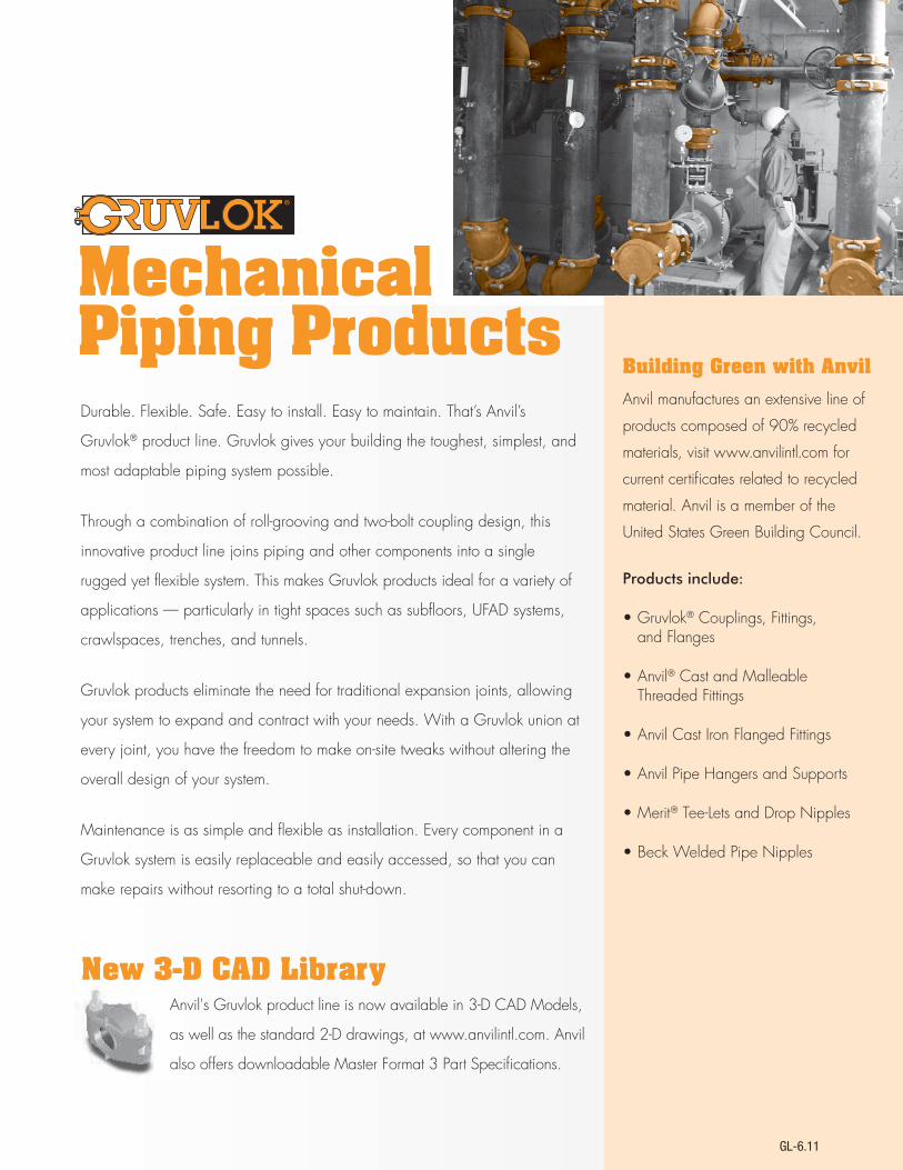
Durable. Flexible. Safe. Easy to install. Easy to maintain. That’s Anvil’s
Gruvlok® product line. Gruvlok gives your building the toughest, simplest, and
most adaptable piping system possible.
Through a combination of roll-grooving and two-bolt coupling design, this
innovative product line joins piping and other components into a single
rugged yet flexible system. This makes Gruvlok products ideal for a variety of
applications — particularly in tight spaces such as subfloors, UFAD systems,
crawlspaces, trenches, and tunnels.
Gruvlok products eliminate the need for traditional expansion joints, allowing
your system to expand and contract with your needs. With a Gruvlok union at
every joint, you have the freedom to make on-site tweaks without altering the
overall design of your system.
Maintenance is as simple and flexible as installation. Every component in a
Gruvlok system is easily replaceable and easily accessed, so that you can
make repairs without resorting to a total shut-down.
Building Green with Anvil
Anvil manufactures an extensive line of
products composed of 90% recycled
materials, visit www.anvilintl.com for
current certificates related to recycled
material. Anvil is a member of the
United States Green Building Council.
Products include:
•Gruvlok® Couplings, Fittings, and Flanges
•Anvil® Cast and Malleable Threaded Fittings
•AnvilCastIronFlangedFittings
•AnvilPipeHangersandSupports
•Merit® Tee-Lets and Drop Nipples
•BeckWeldedPipeNipples
MechanicalPiping Products
7000 Coupling 7001 Coupling 7003 Coupling
7010 Coupling 7011 Coupling 7012 Coupling
Anvil's Gruvlok product line is now available in 3-D CAD Models,
as well as the standard 2-D drawings, at www.anvilintl.com. Anvil
alsooffersdownloadableMasterFormat3PartSpecifications.
New 3-D CAD Library
GL-6.11

IntroductIon
www.anvilintl.com4
Gruvlok di-lok® nipple & di-electric pipe connection
Fig. 7091 - CTS Groove by IPS Groove ..............127
table of contentsintroduction
Gruvlok® Pictorial Parts Index ..................................6-12Agency Approvals ...............................................................13Gruvlok – The Engineered Coupling ....................... 14The Gruvlok Piping Method ..........................................15Gruvlok Couplings for Grooved-End Pipe ............ 16Coupling Data Chart Notes ...........................................17
couplinGs for Grooved-end pipe
Fig. 7401 Rigidlok® Coupling .................................... 18-19Fig. 7401-2 Rigidlok® Coupling.....................................20Fig. 7001 Standard Coupling ...................................21-22Fig. 7001-2 Standard Coupling .....................................23Fig. 7011 Standard Coupling....................................24-25Fig. 7000 Lightweight Coupling ......................... 26-27Fig. 7400 Rigidlite® Coupling ................................28-29Fig. 7003 Hingelok® Coupling ................................ 30-31Fig. 7010 Reducing Coupling ................................. 32-33Fig. 7012 Gruvlok Flange ..........................................34-36Fig. 7013 Gruvlok Flange ........................................... 37-39Fig. 7240 Expansion Joint ........................................40-41
branch outlets
Fig. 7042 Outlet Coupling ......................................42-43Fig. 7045 Clamp-T, FPT Branch .............................44-46Fig. 7046 Clamp-T, Grooved Branch ................. 47-48Fig. 7047, Fig. 7048 & Fig. 7049 Clamp-T, Cross ...49Fig. 7044 Branch Outlet .................................................50
fittinGs for Grooved-end pipe
Technical Data ......................................................................51Fig. 7050 90˚ Elbow ..........................................................52Fig. 7051 45˚ Elbow ............................................................52Fig. 7052 221/2˚ Elbow ......................................................52Fig. 7052i 221/2˚ Elbow .....................................................52Fig. 7053 111/4˚ Elbow ........................................................53Fig. 7050LR 90˚ Long Radius Elbow .........................53Fig. 7051LR 45˚ Long Radius Elbow ...........................53Fig. 7063 Tee with Threaded Branch ....................... 54Fig. 7061 Reducing Tee Standard ............................... 54Fig. 7064 Reducing Tee with Threaded Branch ..55Fig. 7060 Tee .........................................................................55Fig. 7076 Gr x Thd Concentric Reducer................. 56Fig. 7073 & Fig. 7097 Eccentric Reducer ................ 56Fig. 7077, Fig. 7078 & Fig. 7079 Swaged Nipple ...57Fig. 7072 Gr x Gr Concentric Reducer.................... 58Fig. 7072i Gr x Gr Concentric Reducer .................. 58Fig. 7069 45˚ Lateral ......................................................... 59Fig. 7070 45˚ Reducing Lateral ................................... 59Fig. 7066 Tee Wye .............................................................60 Fig. 7067 Reducing Tee Wye ........................................60Fig. 7071 True Wye ............................................................60
Fig. 7087 Gr x FPT Female Thread Adapter .......... 61 Fig. 7055 Gr x MPT 90˚ Adapter Elbow .................. 61 Fig. 7056 Gr x MPT 45˚ Adapter Elbow .................. 61 Fig. 7050RF Grooved x 150# Flanged (GxF) .......... 62Fig. 7084 Groove x Class 150 Flange Nipple ....... 62Fig. 7085 Groove x Class 300 Flange Nipple ...... 62Fig. 7074 Cap .........................................................................63Fig. 7075 Bull Plug ...............................................................63Fig. 7068 Cross .....................................................................63Fig. 7086 Gr x Hose Nipple ..........................................64Fig. 7080 Gr x Gr ................................................................64Fig. 7081 Gr x MPT .............................................................64Fig. 7082 Gr x Bev ..............................................................64Fig. 7062 Bullhead Tee Specialty Tee (Gr x Gr x FPT) . 65Fig. 7065 Standpipe Tee (Gr x Gr x FPT) ................ 65Fig. 7050DR 90˚ Drain Elbow ...................................... 65Fig. 7450 90˚ Short Pattern Elbow ............................66
Fig. 7460 Short Pattern Tee ..........................................66
FIG. 7050-3D LONG RADIUS ELBOWSFig. 7050-3D 90˚ Elbow ...................................................67Fig. 7057-3D 60˚ Elbow ...................................................67Fig. 7051-3D 45˚ Elbow .....................................................67Fig. 7058-3D 30˚ Elbow ...................................................67Fig. 7052-3D 221/2˚ Elbow ..............................................67
Fig. 7053-3D 111/4˚ Elbow.................................................67
FIG. 7050-5D LONG RADIUS ELBOWSFig. 7050-5D 90˚ Elbow ..................................................68Fig. 7057-5D 60˚ Elbow ..................................................68Fig. 7051-5D 45˚ Elbow ....................................................68Fig. 7058-5D 30˚ Elbow ..................................................68Fig. 7052-5D 221/2˚ Elbow .............................................68
Fig. 7053-5D 111/4˚ Elbow ...............................................68
FIG. 7050-6D LONG RADIUS ELBOWSFig. 7050-6D 90˚ Elbow ................................................. 69Fig. 7057-6D 60˚ Elbow .................................................. 69Fig. 7051-6D 45˚ Elbow ................................................... 69Fig. 7058-6D 30˚ Elbow .................................................. 69Fig. 7052-6D 221/2˚ Elbow ............................................. 69Fig. 7053-6D 111/4˚ Elbow ............................................... 69
valves & accessories
KNX Model CA – CBV Accessory......................90-94KNX Model AU – Accessory Union .........90-92, 95KNX Model UV – Integral Ball Valve Union..90-92, 96KNX Model SV – Integral Ball Valve Strainer ..90-92, 97KNX Series Configuration Options ..........................98Model FTV-S & FTV-A Tri-Service Valves ...99-100Fig. 7260 Tee Strainer ............................................ 101-102Model 758G Grooved-End "Wye" Strainer .........103Model 768G Grooved-End "Wye" Strainer ........ 104Fig. 7250 Suction Diffuser .................................. 105-106Model GAV-15 Automatic Air Vent ........................107
Model GAV-30 Automatic Air Vent ...................... 108
ANVILFLEX™ FLEX CONNECTORSFig. AF21-GG Grooved Ends Connector .............. 109Fig. AF21-GF Gr x Class 150 Flanged Flex Connector .................................................................... 110Fig. AF21-FF Class 150 Flanged x Class 150 Flanged Flex Connector........................................................... 110Fig. AF21-RFF Class 150 Flanged x Class 150 Flanged Reducing Flex Connector .....................111Fig. AF21-RGF Gr x Class 150 Flanged Reducing Flex Connector............................................................112
hiGh pressure systems
HIGH PRESSURE COUPLINGSFig. 7004 Coupling .................................................... 114-115Fig. 7004 Coupling with EG® Gasket ............... 116-117
HIGH PRESSURE FITTINGSFig. 7050 EG High Pressure 90˚ LR Elbow .............118Fig. 7051 EG High Pressure 45˚ LR Elbow ...............118Fig. 7060 EG High Pressure Tee ..................................119Fig. 7662 EG High Pressure Header Tee ..................119Fig. 7068 EG High Pressure Cross ..............................119
Series 7700 Butterfly Valve....................................70-74Series 7600 Butterfly Valve ...........................................75Series 8000GR Butterfly Valve ............................76-78Series 171N & 1715 Brass Ball Valve .....................79-80Series 7500 Ball Valve ...............................................81-82Fig. 400G Grooved-End Silent Check Valve ....... 83Series 7800 Check Valve ........................................84-86Series GBV-G & GBV-A Balancing Valves .......87-88Series GBV-S & GBV-T Globe Valves .......................89KNX Model CU – CBV Union ..............................90-94
Gruvlok® cts copper systemTechnical Data .................................................................. 120
Fig. 6400 Rigid Coupling ...............................................121
CTS COPPER SYSTEM FITTINGSFig. 6050 90˚ Elbow ...................................................122Fig. 6051 45˚ Elbow .....................................................122Fig. 6060 Tee ..................................................................122Fig. 6074 End Caps ......................................................122Fig. 6061 (Gr x Gr x Gr) Reducing Tee ...............123Fig. 6064 (Gr x Gr x Cup) Reducing Tee ...........123Fig. 6072 (Gr x Gr) Concentric Reducer .......... 124Fig. 6075 (Gr x Cup) Reducing Adapter .......... 124 Fig. 6084 Flange Adapter ....................................... 124Series 6700 CTS Copper Butterfly Valve ..125-126
GL-7.12

IntroductIon
www.anvilintl.com 5
Intro
duct
ion
Coup
lings
Outle
tsFi
tting
sVa
lves
&
Acce
ssor
ies
High
Pres
sure
DI-L
OK®
Nipp
les
Plai
n-En
dFi
tting
sHD
PECo
uplin
gsSo
ck-It
®
Fitti
ngs
Stai
nles
sSt
eel M
etho
dRo
ll Gr
oove
rsIn
stal
latio
n&
Ass
embl
ySp
ecia
lCo
atin
gsDe
sign
Serv
ices
Tech
nica
lDa
taM
aste
r For
mat
3 Pa
rt Sp
ecs.
Pict
oria
lIn
dex
CTS
Copp
er
Syst
em
table of contentsGruvlok plain end fittinGs
Fig. 7005 Roughneck® Coupling .......................... 128
PLAIN-END FITTINGSTechnical Data ............................................................. 129Fig. 7050P 90˚ Elbow ................................................ 129Fig. 7051P 45˚ Elbow .................................................. 129Fig. 7060P Tee ............................................................... 129Fig. 7068P Cross........................................................... 130Fig. 7061P Reducing Tee .......................................... 130Fig. 7069P 45˚ Lateral................................................ 130Fig. 7071P 90˚ True Wye .......................................... 130Fig. 7050LRP 90˚ LR Elbow .................................... 130Fig. 7051LRP 45˚ LR Elbow ........................................131Fig. 7084P & Fig. 7085P (Plain-End x Class 150 or 300) Flange Nipple .........................................131
Fig. 7075P Bull Plug ......................................................131
ADAPTER NIPPLESFig. 7080P Plain x Grooved .....................................132Fig. 7081P Plain x Thread ..........................................132Fig. 7082P Plain x Bevel .............................................132
Fig. 7077P Swaged Nipple .......................................132
hdpe couplinGs
Fig. 7305 HDPE Coupling .................................133-134Fig. 7307 HDPE Transition Coupling ......... 135-136
Fig. 7312 HDPE Flange Adapter .....................137-138
sock-it® pipinG method fittinGs
Technical Data ..............................................................139Fig. 7100 90˚ Elbow ....................................................139Fig. 7101 90˚ Reducing Elbow ...............................140Fig. 7103 Straight Tee ................................................140Fig. 7107 Coupling ......................................................140Fig. 7105 Reducing Outlet Tee .............................. 141Fig. 7106 Reducing Tee .............................................. 141
stainless steel method
Fig. 7400SS Rigidlite® Coupling ............................142
GRUVLOK STAINLESS STEEL FITTINGSTechnical Data ..............................................................143
TYPE 304 FITTINGSFig. A7050-SS04 90˚ Stainless Steel Elbow .. 144Fig. A7051-SS04 45˚ Stainless Steel Elbow .... 144Fig. A7060-SS04 Stainless Steel Tee ................ 144 Fig. A7074-SS04 Stainless Steel Caps .............. 144Fig. A7061-SS04 Stainless Steel Reducing Tee .145
Fig. A7072-SS04 Stainless Steel Concentric Reducer .145
TYPE 316 FITTINGSFig. 7050SS 90˚ Stainless Steel Elbow ............. 146Fig. 7051SS 45˚ Stainless Steel Elbow ............... 146Fig. 7060SS Stainless Steel Tee ........................... 146
roll GrooversModel 1007 & 3007 Roll Groovers .......... 148-149
Model 3006 Roll Groover ..............................150-151
couplinG installation & assemblySpecified Bolt Torque ...............................................152Fig. 7401 Rigidlok® Coupling ...................................153Fig. 7001 Standard Coupling ..................................154Fig. 7001-2 & Fig. 7401-2 Two Piece Large Dia. Couplings ....................155Fig. 7011 Standard Coupling................................... 156Fig. 7000 Lightweight Coupling ..........................157Fig. 7400 Rigidlite® Coupling ................................ 158Fig. 6400 Rigid Coupling ........................................ 159Fig. 7003 Hingelok® Coupling ...............................160Fig. 7010 Reducing Coupling ................................. 161Fig. 7012 Gruvlok Flange (2"-12") .................. 162-163Fig. 7012 Gruvlok Flange (14"-24") ........................ 164Fig. 7042 Outlet Coupling ..................................... 165Fig. 7045 & Fig. 7046 Clamp-T® Branch Outlets...................................................... 166Fig. 7044 Branch Outlet ...........................................167Fig. 7005 Roughneck® Coupling .......................... 168Fig. 7004 High Pressure Coupling ...................... 169Fig. 7004 Coupling with End Guard Gasket . 170Fig. 7305 HDPE Coupling ......................................... 171Fig. 7307 HDPE Transition Coupling ..................172Fig. 7312 HDPE Flange Adapter .............................173Gruvlok Sock-It® Fitting ...........................................174Model FTV Tri-Service Valve ....................... 175-178Series GBV-S & GBV-T Circuit Balancing Valves............................................179-181AnvilFlex™ Flex Connectors ................................... 182
desiGn servicesBasic & Extended Services ..................................... 184Drawing Examples ..............................................185-187
pictorial indexPipe Fittings Products ....................................239-248Pipe Hanger Products ..................................... 249-253Anvil-Strut™ Products .................................... 254-260
indexNumeric Index ............................................................. 261
Section 15050 .......................................................214-219Section 15300 ......................................................219-223Section 15400 .....................................................223-228Section 15500 ..................................................... 228-232Section 15600 ......................................................232-238
master format3 part specification
terms & conditionsProduct Terms & Conditions ................................262
Anvil Special Coatings ..............................................183
special coatinGs
technical dataTable of Contents ...................................................... 188Gruvlok® Lubricants .............................................. 189Specified Bolt Torque ...........................................190Design Factors..........................................................190
cross referenceGruvlok Product Cross Reference .....................263
GL-7.12
Gruvlok Flow Control Components .............. 191Gruvlok Gasket Styles .......................................... 192Gasket Grade Index ............................................... 193Gruvlok Gasket Recommendations ......194-195Movement-Applications .............................196-197Coupling Working Pressure Rating on Light Wall Roll Grooved Steel Pipe ........ 198Coupling Working Pressure Rating on Roll Grooved ISO Steel Pipe ...................... 199Coupling & Flange Working Pressure Rating on 304 & 316 Stainless Steel Roll Grooved Pipe ..200Pipe Support ....................................................201-203Coupling Flexibility .................................... 204-205Drafting Symbols for Gruvlok Piping Systems...206Pipe Preparation ........................................... 207-208Roll Groove Specifications ...............................209Cut Groove Specifications .................................210Cut Groove End Guard® Specification .......... 211Roll Groove End Guard® Specification.......... 211Gruvlok CTS Copper System Roll Groove Specification .............................. 212Fig. 7240 Order Form .............................................213
Fig. 7074SS Stainless Steel Caps ......................... 146Fig. 7061SS Stainless Steel Reducing Tee............147Fig. 7072SS Stainless Steel Concentric Reducer ..147Fig. 7073SS Stainless Steel Eccentric Reducer..147Fig. 7084SS Stainless Steel Flange Adapter Type 304 (Groove x Class 150) .....................147

IntroductIon
www.anvilintl.com6
Gruvlok® pictorial parts index
couplinGsFig. 7401 Pages 18-19
Rigidlok® Coupling
Size Range: 11/2" - 14" Size Range: 16" Size Range: 18" - 24"
Fig. 7011 Pages 24-25
Standard CouplingSize 30"
Fig. 7400 Pages 28-29
300 PSI Rigidlite® CouplingSize Range: 1" - 8"
Fig. 7000 Pages 26-27
Lightweight CouplingSize Range: 1" - 8"
Fig. 7003 Pages 30-31
Hingelok® CouplingSize Range: 1" - 4" and5" - 8"
Fig. 7010 Pages 32-33
Reducing CouplingSize Range: 2" x 11/2" thru8"x 6"
Fig. 7013 Pages 37-39
Gruvlok Flanges(#300 Flange)Size Range: 2" - 12"
Fig. 7012 Pages 34-36
Gruvlok Flanges
Size Range: 2" - 12" Size Range: 14" - 24"
Fig. 7240 Pages 40-41
Expansion JointsSize Range: 2" - 12"
NIPPLE COUPLING END ADAPTER
RG
VU
OLK
007 .GIF ''4
0
RG
VU
OLK
007 .GIF ''4
0
RG
VU
OLK
0 07 .GIF ''4
0
RG
VU
OLK
007 .GIF '' 4
0
RG
VU
OLK
0 07 .GIF ' '4
0
branch outletsFig. 7042 Pages 42-43
Outlet CouplingSize Range: 11/2" - 6"
Fig. 7042FFemale IPS Outlet
Fig. 7042MMale IPS Outlet
Fig. 7042GGrooved Outlet
Clamp-T, FPT BranchSize Range: 3" x 11/4" thru
8" x 4"
(U-Bolt)Size Range: 21/2" x 1/2" thru
4" x 1"
Fig. 7046 Pages 47-48
Clamp-T, Grooved BranchSize Range: 3" x 11/4" thru
8" x 4"
(U-Bolt)Size Range: 21/2" x 11/4" thru
21/2" x 11/2"
Fig. 7047, Fig. 7048 & Fig. 7049 Page 49
Clamp-T CrossSize Range: 2" x 1/2" thru 8" x 4"
Fig. 7047Thread x Thread
Fig. 7048Groove x Groove
Fig. 7049Groove x Thread
GL-7.12
Fig. 7001 Pages 21-22
Standard Coupling
Size Range: 1" - 14" Size Range: 16" - 24" Size Range: 28" - 30"
Fig. 7401-2 Page 20
Rigidlok® CouplingSize Range: 14" - 24"
Fig. 7001-2 Page 23
Standard CouplingSize Range: 14" - 24"
Fig. 7044 Page 50Fig. 7045 Pages 44-46
Branch OutletSize Range: 11/4" x 1/2" thru
21/2" x 1"

IntroductIon
www.anvilintl.com 7
Intro
duct
ion
Coup
lings
Outle
tsFi
tting
sVa
lves
&
Acce
ssor
ies
High
Pres
sure
DI-L
OK®
Nipp
les
Plai
n-En
dFi
tting
sHD
PECo
uplin
gsSo
ck-It
®
Fitti
ngs
Stai
nles
sSt
eel M
etho
dRo
ll Gr
oove
rsIn
stal
latio
n&
Ass
embl
ySp
ecia
lCo
atin
gsDe
sign
Serv
ices
Tech
nica
lDa
taM
aste
r For
mat
3 Pa
rt Sp
ecs.
Pict
oria
lIn
dex
CTS
Copp
er
Syst
em
Fig. 7060 Page 55
TeeSize Range: 1" - 24"
Grooved fittinGsFig. 7050 Page 52
90˚ ElbowSize Range: 1" - 24"
Fig. 7051 Page 52
45˚ ElbowSize Range: 1" - 24"
Fig. 7052 Page 52
221/2˚ ElbowSize Range: 1" - 24"
Fig. 7053 Page 53
111/4˚ ElbowSize Range: 1" - 24"
Fig. 7050LR Page 53
90˚ Long Radius ElbowSize Range: 1" - 24"
Fig. 7051LR Page 53
45˚ Long Radius ElbowSize Range: 1" - 24"
Fig. 7063 Page 54
Tee with Threaded BranchSize Range: 1" - 12"
Fig. 7061 Page 54
Reducing Tee StandardSize Range: 11/4" x 11/4" x 1"thru 24" x 24" x 20"
Fig. 7064 Page 55
Reducing Tee with Threaded BranchSize Range: 2" x 2" x 3/4"thru 24" x 24" x 12"
Fig. 7076 Page 56
Gr x Thd Concentric ReducerSize Range: 11/2" x 1" thru 6" x 5"
Fig. 7072 Page 58
Gr x Gr Concentric ReducerSize Range: 11/4" x 1" thru 24" x 20"
Fig. 7073 & Fig. 7097 Page 56
Eccentric ReducersSize Range: 11/4" x 1" thru 24" x 20"
Fig. 7073Groove x Groove
Fig. 7097Groove x Thread
Fig. 7077, 7078 & 7079 Page 57
Swaged NipplesSize Range: 2" x 1" thru 6" x 5"
Fig. 7077Groove x Groove
Fig. 7078Groove x Thread
Fig. 7079Groove x Bevel
Fig. 7069 Page 59
45˚ LateralSize Range: 1" - 24"
Fig. 7070 Page 59
45˚ Reducing LateralSize Range: 3" x 3" x 2" thru 24" x 24" x 20"
Fig. 7071 Page 60
True WyeSize Range: 1" - 24"
Fig. 7066 Page 60
Tee WyeSize Range: 2" x 2" x 2" thru 12" x 12" x 12"
Fig. 7067 Page 60
Reducing Tee WyeSize Range: 4" x 3" x 3" thru 8" x 6" x 8"
Fig. 7087 Page 61
Female Thread AdapterSize Range: 1" - 4"
Fig. 7055 Page 61
90˚ Adapter ElbowSize Range: 1" - 6"
Fig. 7056 Page 61
45˚ Adapter ElbowSize Range: 1" - 6"
Fig. 7050RF Page 62
Reducing BaseSupport ElbowGroove x 150# Flange (GxF) Size Range: 6" x 4" thru 12" x 10"
Fig. 7084 Page 62
Groove x Class 150Flange NippleSize Range: 1" - 24"
Fig. 7085 Page 62
Groove x Class 300Flange NippleSize Range: 3" - 8"
Fig. 7074 Page 63
CapSize Range: 11/4" - 24"
Fig. 7075 Page 63
Bull PlugSize Range: 2" - 6"
Fig. 7068 Page 63
CrossSize Range: 1" - 24"
Fig. 7086 Page 64
Groove x Hose NippleSize Range: 1" - 12"
Fig. 7065 Page 65
Standpipe Tee (Gr x Gr x FPT)Size Range: 4" x 4" x 21/2" thru 6" x 6" x 21/2"
Fig. 7062 Page 65
Bullhead Tee Specialty Tees (Gr x Gr x FPT)Size Range: 5" x 5" x 8" thru 6" x 6" x 8"
Fig. 7050DR Page 65
90˚ Drain ElbowSize Range: 11/4" - 12"
GL-7.12
Fig. 7072i Page 58
Gr x Gr Concentric ReducerSize Range: 11/4" x 1" thru 10" x 8"
Fig. 7052i Page 52
221/2˚ ElbowSize Range: 1" - 12"

IntroductIon
www.anvilintl.com8
Grooved fittinGsFig. 7050-3D Page 67
Long Radius ElbowsSize Range: 2" - 24"
Fig. 7050-3D90˚ Elbow
Fig. 7057-3D60˚ Elbow
Fig. 7051-3D45˚ Elbow
Fig. 7058-3D30˚ Elbow
Fig. 7052-3D221/2˚ Elbow
Fig. 7053-3D111/4˚ Elbow
Fig. 7050-5D Page 68
Long Radius ElbowsSize Range: 2" - 24"
Fig. 7050-5D90˚ Elbow
Fig. 7057-5D60˚ Elbow
Fig. 7051-5D45˚ Elbow
Fig. 7058-5D30˚ Elbow
Fig. 7052-5D221/2˚ Elbow
Fig. 7053-5D111/4˚ Elbow
Fig. 7050-6D Page 69
Long Radius ElbowsSize Range: 2" - 24"
Fig. 7050-6D90˚ Elbow
Fig. 7057-6D60˚ Elbow
Fig. 7051-6D45˚ Elbow
Fig. 7058-6D30˚ Elbow
Fig. 7052-6D221/2˚ Elbow
Fig. 7053-6D111/4˚ Elbow
Fig. 7080,Fig. 7081 &Fig. 7082 Page 64
NipplesSize Range: 1" - 12"
Fig. 7080Groove x Groove
Fig. 7081Groove x MPT
Fig. 7082Groove x Bevel
valves & accessoriesSeries 7700 Pages 70-74
Butterfly ValveSize Range: 2" - 12"
AN-7722-3Series 7700
Butterfly Valvewith Gear Operator
AN-7721-3Series 7700
Butterfly Valvewith 10 Position Lever Lock
Series 7600 Page 75
Butterfly ValveSize Range: 2" - 6"
Series 8000GRPages 76-78
Butterfly ValveSize Range: 14" - 24"
Series 171 & 1715 Pages 79-80
Brass Ball Valve171N – Size Range: 1/4" - 4"1715 – Size Range: 1/2" - 4"
Series 7500Pages 81-82
Ball ValveSize Range: 2" - 6"
Fig. 400G Page 83
Grooved-EndSilent Check ValveSize Range: 2" - 10"
Series 7800Pages 84-86
Check Valvefor use in Grooved-End Piping SystemsSize Range: 2" - 12"
GBV-G Page 87
Balancing ValveDuctile Iron, Grooved-End StraightSize Range: 21/2" - 12"
GBV-A Page 88
Balancing ValveDuctile Iron, Grooved-End AngleSize Range: 21/2" - 12"
GBV-S & GBV-TPage 89
Globe ValvesCast Bronze, Solder (GBV-S)Cast Bronze, Threaded (GBV-T)Size Range: 1/2" - 2"
GL-7.12
Fig. 7450 Page 66
90˚ Short Pattern ElbowSize Range: 2" - 8"
Fig. 7460 Page 66
Short Pattern TeeSize Range: 2" - 8"

IntroductIon
www.anvilintl.com 9
Intro
duct
ion
Coup
lings
Outle
tsFi
tting
sVa
lves
&
Acce
ssor
ies
High
Pres
sure
DI-L
OK®
Nipp
les
Plai
n-En
dFi
tting
sHD
PECo
uplin
gsSo
ck-It
®
Fitti
ngs
Stai
nles
sSt
eel M
etho
dRo
ll Gr
oove
rsIn
stal
latio
n&
Ass
embl
ySp
ecia
lCo
atin
gsDe
sign
Serv
ices
Tech
nica
lDa
taM
aste
r For
mat
3 Pa
rt Sp
ecs.
Pict
oria
lIn
dex
CTS
Copp
er
Syst
em
valves & accessories
FTV-S Pages 99-100
Tri-Service Valve (Straight)Size Range: 21/2" - 12"
FTV-A Pages 99-100
Tri-Service Valve(Angle Body)Size Range: 21/2" - 12"
Fig. 7260 Pages 101-102
Gruvlok Tee StrainerSize Range: 2" - 18"
Model 758G Page 103
Grooved-End"Wye" StrainerSize Range: 2" - 12"
Model 768G Page 104
Grooved-End"Wye" StrainerSize Range: 2" - 12"
Fig. 7250 Pages 105-106
Suction DiffuserSize Range: 21/2" x 21/2" thru 16" x 14"
FIG. 7250
Model GAV-15Page 107
Automatic Air Ventfor Ultimate PerformanceSize Range: 1/2" - 1"
Model GAV-30Page 108
Automatic Air Ventfor Ultimate PerformanceSize Range: 1/2" - 3/4"
AnvilFlex™ AF21 Series Pages 109-112
Flex ConnectorsSize Range: 2" - 12"
Fig. AF21-GGGrooved Ends
Fig. AF21-GFGrooved x Class
150 Flanged
Fig. AF21-FFClass 150 Flanged xClass 150 Flanged
Fig. AF21-RFFReducing Class 150
Flanged xClass 150 Flanged
Fig. AF21-RGFReducing Grooved xClass 150 Flanged
hiGh pressure systems
Fig. 7004Pages 114-115
CouplingSize Range: 2" - 12"
Fig. 7004 with EG® GasketPages 116-117
Coupling with EG GasketSize Range: 2" - 12"
GL-7.12
Fig. 7050 EG Page 118
High Pressure 90˚ LR ElbowSize Range: 2" - 12"
Fig. 7051 EG Page 118
High Pressure 45˚ LR ElbowSize Range: 2" - 6"
Fig. 7662 EG Page 119
High Pressure Header TeeSize: 2"
Fig. 7060 EG Page 119
High Pressure TeeSize Range: 2" - 6"
Fig. 7068 EG Page 119
High Pressure CrossSize Range: 2" - 6"
KNX Model CU Pages 90-94
CBV UnionSize Range: 1/2" - 2"
KNX Model CA Pages 90-94
CBV AccessorySize Range: 1/2" - 2"
KNX Model AU Pages 90-92, 95
Accessory UnionSize Range: 1/2" - 2"
KNX Model UV Pages 90-92, 96
Integral Ball Valve UnionSize Range: 1/2" - 2"
KNX Model SV Pages 90-92, 97
Integral Ball Valve StrainerSize Range: 1/2" - 2"

IntroductIon
www.anvilintl.com10
di-lok® nippleFig. 7091 Page 127
Gruvlok DI-LOK® Nipple Di-Electric Pipe ConnectionCTS Groove x IPS GrooveSize Range: 3/4" - 6"
Fig. 7068P Page 130
CrossSize Range: 2" - 8"
Fig. 7069P Page 130
45˚ LateralSize Range: 2" - 8"
Fig. 7071P Page 130
90˚ True WyeSize Range: 2" - 8"
Fig. 7084P & Fig. 7085P Page 131
Flange Nipples
Plain-End x Class 150Size Range: 2" - 8"
Plain-End x Class 300Size Range: 2" - 8"
Fig. 7075P Page 131
Bull PlugSize Range: 2" - 8"
plain-end fittinGsFig. 7005 Page 128
Roughneck® CouplingSize Range: 2" - 16"
Fig. 7050P, Fig. 7051P & Fig. 7060P Page 129
Gruvlok Plain-End FittingsSize Range: 2" - 8"
Fig. 7050P90˚ Elbow
Fig. 7051P45˚ Elbow
Fig. 7060PTee
Fig. 7061P Page 130
Reducing TeeSize Range: 3" x 3" x 2" thru 12" x 12" x 10"
Fig. 7050LRPPage 130
90˚ LR ElbowSize Range: 2" - 8"
Fig. 7051LRPPage 131
45˚ LR ElbowSize Range: 2" - 8"
Fig. 7080P, Fig. 7081P & Fig. 7082P Page 132
Adapter NipplesSize Range: 2" - 8"
Fig. 7077P Page 132
Swaged NippleSize Range: 21/2" x 2" thru 8" x 6"
Fig. 7080PPlain x Groove
Fig. 7081PPlain x Thread
Fig. 7082PPlain x Bevel
hdpe couplinGsFig. 7305 Pages 133-134
HDPE CouplingSize Range: 2" - 12"
Fig. 7307 Pages 135-136
HDPE Transition CouplingSize Range: 2" - 12"
Fig. 7312 Pages 137-138
HDPE Flange AdapterSize Range: 4" - 8"
GL-7.12
cts copper systemFig. 6400 Page 121
Rigid CouplingSize Range: 2" - 8"
Fig. 6064 Page 123
Reducing Tee (Gr x Gr x Cup)Size Range: 2" x 2" x 3/4" thru 4" x 4" x 11/2"
Fig. 6074 Page 122
End CapSize Range: 2" - 6"
Fig. 6075 Page 124
Reducing Adapter (Gr x Cup)Size Range: 2" x 1" thru4" x 2"
Fig. 6084 Page 124
Flange AdapterSize Range: 2" - 6"
Series 6700 CTS Copper Butterfly Valve Pages 125-126
Size Range: 21/2" - 6"
Fig. 6050 Page 122
90˚ ElbowSize Range: 2" - 8"
Fig. 6051 Page 122
45˚ ElbowSize Range: 2" - 8"
Fig. 6060 Page 122
TeeSize Range: 2" - 8"
Fig. 6061 Page 123
Reducing Tee (Gr x Gr x Gr)Size Range: 21/2" x 21/2" x 2" thru 6" x 6" x 5"
Fig. 6072 Page 124
Concentric Reducer (Gr x Gr)Size Range: 21/2"x 2" thru 8" x 6"

IntroductIon
www.anvilintl.com 11
Intro
duct
ion
Coup
lings
Outle
tsFi
tting
sVa
lves
&
Acce
ssor
ies
High
Pres
sure
DI-L
OK®
Nipp
les
Plai
n-En
dFi
tting
sHD
PECo
uplin
gsSo
ck-It
®
Fitti
ngs
Stai
nles
sSt
eel M
etho
dRo
ll Gr
oove
rsIn
stal
latio
n&
Ass
embl
ySp
ecia
lCo
atin
gsDe
sign
Serv
ices
Tech
nica
lDa
taM
aste
r For
mat
3 Pa
rt Sp
ecs.
Pict
oria
lIn
dex
CTS
Copp
er
Syst
em
sock-it® methodFig. 7100 Page 139
90˚ Elbow(Sock-It x Sock-It)Size Range: 1" - 2"
Fig. 7101 Page 140
90˚ Reducing Elbow(Sock-It x NPT)Size Range: 1" x 1/2" thru 11/2" x 1"
Fig. 7103 Page 140
Straight Tee(Sock-It x Sock-It x Sock-It)Size Range: 1" - 2"
Fig. 7105 Page 141
Reducing Outlet Tee(Sock-It x Sock-It x NPT)Size Range: 1" x 1" x 1/2" thru 21/2 x 21/2 x 1"
Fig. 7106 Page 141
Reducing Tee(Sock-It x Sock-It x NPT)Size Range: 11/4" x 1" x 1/2" thru 2 x 11/2 x 1"
Fig. 7107 Page 140
Coupling(Sock-It x Sock-It)Size Range: 1" - 2"
stainless steel method
Fig. 7400SS Page 142
Rigidlite® CouplingSize Range: 11/4" - 8"
Fig. 7060-SS04Page 144
Stainless Steel TeeSize Range: 11/4" - 12"
Fig. 7074-SS04Page 144
Stainless Steel CapSize Range: 11/4" - 12"
Fig. 7084SSPage 147
Stainless Steel Flange AdapterSize Range: 2" - 12"
Fig. 7050-SS04Page 144
90˚ Stainless Steel ElbowSize Range: 11/4" - 12"
Fig. 7051-SS04Page 144
45˚ Stainless Steel ElbowSize Range: 11/4" - 12"
Fig. 7061-SS04Page 145
Stainless Steel Reducing TeeSize Range: 11/2" x 11/4" thru 12" x 10"
Fig. 7072-SS04Page 145
Stainless Steel Concentric ReducerSize Range: 11/2" x 11/4" thru 12" x 10"
ss type 304 fittinGs
ss type 316 fittinGsFig. 7060SSPage 146
Stainless Steel TeeSize Range:11/4" - 12"
Fig. 7074SSPage 146
Stainless Steel CapSize Range: 11/4" - 12"
Fig. 7061SSPage 147
Stainless Steel Reducing TeeSize Range: 11/2" x 11/2" x 3/4" thru 8" x 8" x 6"
Fig. 7072SSPage 147
Stainless Steel Concentric ReducerSize Range: 11/2" x 1" thru 8" x 6"
Fig. 7050SSPage 146
90˚ Stainless Steel ElbowSize Range:11/4" - 12"
Fig. 7051SSPage 146
45˚ Stainless Steel ElbowSize Range:11/4" - 12"
Fig. 7073SSPage 147
Stainless Steel Eccentric ReducerSize Range: 11/2" x 1" thru 8" x 6"
GL-7.12

IntroductIon
www.anvilintl.com12GL-6.11
roll GrooversGruvlok roll grooving technology is protected byU.S. Patents 5450738, 5570603, 5778715 and others pending.
Model 1007 Pages 148-149
Roll GrooverGroover Capability: 2" - 16"
Model 3007 Pages 148-149
Roll GrooverGroover Capability: 2" - 16"
Model 3006 Pages 150-151
Roll GrooverGroover Capability: 2" - 12"

IntroductIon
www.anvilintl.com 13
Intro
duct
ion
Coup
lings
Outle
tsFi
tting
sVa
lves
&
Acce
ssor
ies
High
Pres
sure
DI-L
OK®
Nipp
les
Plai
n-En
dFi
tting
sHD
PECo
uplin
gsSo
ck-It
®
Fitti
ngs
Stai
nles
sSt
eel M
etho
dRo
ll Gr
oove
rsIn
stal
latio
n&
Ass
embl
ySp
ecia
lCo
atin
gsDe
sign
Serv
ices
Tech
nica
lDa
taM
aste
r For
mat
3 Pa
rt Sp
ecs.
Pict
oria
lIn
dex
CTS
Copp
er
Syst
em
products for Grooved pipinG systemThe Gruvlok® System has been manufactured since the late 1960’s. The Gruvlok product line has grown from standard couplings and fittings to today’s extensive range of grooved product, plain-end product, butterfly valves, check valves, pump protection components, pipe preparation tools and various accessories.
AnSI American National Standards Institute
API American Petroleum Institute: API Std. 5L, Sect. 7.5
ASHrAE American Society of Heating, Refrigerating and Air Conditioning Engineers
ASME American Society of Mechanical Engineers: Power Piping, B 31.1; Chemical Plant and Petroleum Refinery Piping, B 31.3; Refrigeration Piping, B 31.5; Building Services Piping, B 31.9; Slurry Pipelines, B 31.11
AStM American Society of Testing and Materials: F 1476, F 1387
AWWA American Water Works Association: C 606
BV Bureau Veritas
cdF California State Fire Marshal
coE Corps of Engineers: CEGS 15000
cSA Canadian Standards Association: B 242
dnV Det Norske Veritas
Hong Kong Fire Services Board
New Zealand Insurance Council
New Zealand Building Act. (1991)
Gruvlok is part of our overall commitment to provide today’s piping industry with tomorrow’s products.
InduStrY & GoVErnMEnt StAndArdS & APProVALS
FAA Federal Aviation Administration: HVAC, Plumbing, Fire Protection
FHA Federal Housing Administration
FM Factory Mutual Engineering Corp.
GSA General Services Administration: 15000 Series
IAPMo International Association of Plumbing & Mechanical Officials
LPc Loss Prevention Council
MEA Materials & Equipment Acceptance
MIL Military Specifications: MILP-10388 Fittings; MIL-C-10387 Couplings; MIL-P-11087A(CE) Steel Pipe, Grooved MIL-I-45208 Inspection Procedure
nASA National Aeronautics and Space Administration: 15000 Series
nAVFAc Naval Facilities Engineering Command: NFGS 15000 Series
nFPA National Fire Protection Association
nIH National Institute of Health (Dept. of Health): 15000 Series
nSF NSF International
nY-BSA New York Board of Standards and Appeals
nYc New York City
tVA Tennessee Valley Authority: Fire protection, storm drains
uL Underwriter’s Laboratories, Inc.
uLc Underwriter’s Laboratories of Canada
Bureau of Marine Inspection: Salt and fresh water, oil transfer
Bureau of Public Roads; Div. of Bridges: Drain lines and bridge crossings
Canadian Coast Guard
U.S. Coast Guard –Approves each vessel individually
uSGBc United States Green Building Council
VA Veterans Affairs : 15000 Series
VdS Verband der Sachversicherer e.V.
AGEncY APProVALS
note: Please refer to product specific pages for exact listings and approvals related to a specific size for a specific product.
GL-7.12
For Listings/Approval Details and Limitations, visit our website at www.anvilintl.com or contact an Anvil® Sales Representative.
VdS
9001:20089001:2008ISO ISO

IntroductIon
www.anvilintl.com14
Gruvlok® – the enGineered couplinGHouSInG (A) FLEXIBLE or rIGIdThe Gruvlok Coupling housing is designed to self-center around the pipe. The housing encircles and retains the gasket against the application of internal system pressure or vacuum.
The housing key sections fit into and engage the pipe-end grooves around the entire pipe circumference, thus restraining the pipe ends from separation due to the application of internal pressure.
Flexible Couplings provide designed-in clearances between the housing key sections and the pipe grooves to permit both angular and longitudinal movement of the pipe. Rigid couplings grip the pipe and lock the joint into position.
All housings are coated with paint for general service applications. The paint serves to provide protection against normal atmospheric corrosion. However, for couplings used in corrosive environments, hot-dip galvanizing, and stainless steel are available.
GASKEt (B)The unique single piece “C” style design of the gasket has been engineered to provide a pressure responsive, leak-tight seal in both pressure and vacuum applications without the aid of external forces. The “lips” of the gasket are molded so that upon installation onto the pipe ends they provide compression against the pipe surface to establish the leak-tight seal.
The gasket cavity functions as a “pressure reservoir”. Pressure within the pipe system is applied to the internal surfaces of the gasket which increases the sealing force and enhances the leak-tight seal. In vacuum systems, non-pressure-responsive seals tend to “lift off” the pipe, producing leak paths. However, the Gruvlok gasket reacts to the negative pressure (higher outside atmospheric pressure) as to improve the sealing capability of the gasket.
GasketReactionto Pressure
GasketReactionto Vacuum
BoLtS And nutS (c) Heat treated oval neck track head bolts serve to connect and secure the housing segments together. The oval neck design prevents turning of the bolt while tightening the hex nut with a single wrench. The bolt size and corresponding wrench (or socket) size for the hex nuts are shown in the chart below.
A
B
D
C
GrooVEd PIPE EndS (d) The ends of the pipe must have a groove in them which may be either cut grooved or roll grooved. The grooved pipe ends engage the coupling keys, thus, providing a self-restraining, mechanical joint capable of resisting the separation of the pipe ends due to the application of system pressure. The groove diameters must be dimensionally accurate to obtain the maximum benefit of the Gruvlok Coupling.
GL-6.11

IntroductIon
www.anvilintl.com 15
Intro
duct
ion
Coup
lings
Outle
tsFi
tting
sVa
lves
&
Acce
ssor
ies
High
Pres
sure
DI-L
OK®
Nipp
les
Plai
n-En
dFi
tting
sHD
PECo
uplin
gsSo
ck-It
®
Fitti
ngs
Stai
nles
sSt
eel M
etho
dRo
ll Gr
oove
rsIn
stal
latio
n&
Ass
embl
ySp
ecia
lCo
atin
gsDe
sign
Serv
ices
Tech
nica
lDa
taM
aste
r For
mat
3 Pa
rt Sp
ecs.
Pict
oria
lIn
dex
CTS
Copp
er
Syst
em
The flexibility designed into the Gruvlok coupling will accommodate misalignments caused by imprecise locationof pipe opening through walls and floors, will provide pitch for drainage piping systems and facilitate laying pipe on uneven terrain, thus permitting deflection in any direction.
the Gruvlok® pipinG methodGruvlok couplings and grooved-end fittings are widely used for joining pipe in a wide variety of piping systems. Gruvlok couplings for grooved-end pipe are designed to provide a self-centering joint which accommodates the application of pressure, vacuum and other external forces, while limiting the burdensome need for special supports, expansion joints, etc.
The Gruvlok piping method offers many mechanical design features which benefit the design engineer, the contractor, and the end user. Utilization of the functional characteristics of the Gruvlok coupling will aid in pipe system design and must be considered for proper installation, assembly and performance.
The design factors presented in the Gruvlok technical data section should always be referenced to when designing any grooved piping system to obtain the maximum benefit of the Gruvlok piping method.
GruVLoK FEAturES
riGidity or flexibilityCouplings are available where rigid connections are required. Couplings with flexible design allow for pipe expansion and contractions with temperature changes. The need for an expansion joint is minimized or eliminated.
self restrained jointThe couplings engage the pipe around the entire circumference and restrain the pipe ends from separation due to pressure and other forces, up to the maximum coupling rated working pressure.
ENDLOAD
ENDLOAD
union at every jointGruvlok couplings can be disassembled easily permitting maintenance and servicing of the piping system. It will facilitate periodic rotation of pipe to distribute internal wear from slurries or other abrasive media.
stress-free systemFlexibility designed in the Gruvlok coupling absorbs and eliminates stress from settlement of buried pipe or those induced by seismic tremors.
minimizes noise & vibrationThe resilient elastomeric gasket and pre-designed gap of the Gruvlok coupling help isolate and absorb noise and vibration, this minimizes vibration transmission.
accommodates misaliGnment and joint deflection
GL-6.11
IntroductIon
www.anvilintl.com16
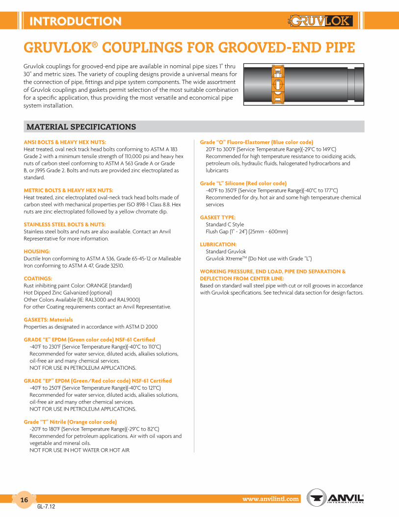
Gruvlok® couplinGs for Grooved-end pipeGruvlok couplings for grooved-end pipe are available in nominal pipe sizes 1" thru 30" and metric sizes. The variety of coupling designs provide a universal means for the connection of pipe, fittings and pipe system components. The wide assortment of Gruvlok couplings and gaskets permit selection of the most suitable combination for a specific application, thus providing the most versatile and economical pipe system installation.
material specifications
AnSI BoLtS & HEAVY HEX nutS:Heat treated, oval neck track head bolts conforming to ASTM A 183 Grade 2 with a minimum tensile strength of 110,000 psi and heavy hex nuts of carbon steel conforming to ASTM A 563 Grade A or Grade B, or J995 Grade 2. Bolts and nuts are provided zinc electroplated as standard.
MEtrIc BoLtS & HEAVY HEX nutS:Heat treated, zinc electroplated oval-neck track head bolts made of carbon steel with mechanical properties per ISO 898-1 Class 8.8. Hex nuts are zinc electroplated followed by a yellow chromate dip.
StAInLESS StEEL BoLtS & nutS:Stainless steel bolts and nuts are also available. Contact an AnvilRepresentative for more information.
HouSInG:Ductile Iron conforming to ASTM A 536, Grade 65-45-12 or Malleable Iron conforming to ASTM A 47, Grade 32510.
coAtInGS:Rust inhibiting paint Color: ORANGE (standard)Hot Dipped Zinc Galvanized (optional)Other Colors Available (IE: RAL3000 and RAL9000)For other Coating requirements contact an Anvil Representative.
GASKEtS: MaterialsProperties as designated in accordance with ASTM D 2000
GrAdE “E” EPdM (Green color code) nSF-61 certified-40°F to 230°F (Service Temperature Range)(-40°C to 110°C)Recommended for water service, diluted acids, alkalies solutions, oil-free air and many chemical services.
NOT FOR USE IN PETROLEUM APPLICATIONS.
GrAdE “EP” EPdM (Green/red color code) nSF-61 certified-40°F to 250°F (Service Temperature Range)(-40°C to 121°C)Recommended for water service, diluted acids, alkalies solutions, oil-free air and many other chemical services.NOT FOR USE IN PETROLEUM APPLICATIONS.
Grade “t” nitrile (orange color code)-20°F to 180°F (Service Temperature Range)(-29°C to 82°C)Recommended for petroleum applications. Air with oil vapors andvegetable and mineral oils.NOT FOR USE IN HOT WATER OR HOT AIR
Grade “o” Fluoro-Elastomer (Blue color code)20°F to 300°F (Service Temperature Range)(-29°C to 149°C)Recommended for high temperature resistance to oxidizing acids,petroleum oils, hydraulic fluids, halogenated hydrocarbons and lubricants
Grade “L” Silicone (red color code)-40°F to 350°F (Service Temperature Range)(-40°C to 177°C)Recommended for dry, hot air and some high temperature chemical services
GASKEt tYPE:Standard C StyleFlush Gap (1" - 24") (25mm - 600mm)
LuBrIcAtIon:Standard GruvlokGruvlok XtremeTM (Do Not use with Grade “L”)
WorKInG PrESSurE, End LoAd, PIPE End SEPArAtIon & dEFLEctIon FroM cEntEr LInE:Based on standard wall steel pipe with cut or roll grooves in accordance with Gruvlok specifications. See technical data section for design factors.
GL-7.12

IntroductIon
www.anvilintl.com 17
Intro
duct
ion
Coup
lings
Outle
tsFi
tting
sVa
lves
&
Acce
ssor
ies
High
Pres
sure
DI-L
OK®
Nipp
les
Plai
n-En
dFi
tting
sHD
PECo
uplin
gsSo
ck-It
®
Fitti
ngs
Stai
nles
sSt
eel M
etho
dRo
ll Gr
oove
rsIn
stal
latio
n&
Ass
embl
ySp
ecia
lCo
atin
gsDe
sign
Serv
ices
Tech
nica
lDa
taM
aste
r For
mat
3 Pa
rt Sp
ecs.
Pict
oria
lIn
dex
CTS
Copp
er
Syst
em
Gruvlok Couplings are identified by either the nominal ANSI pipe size in inches or pipe O.D. in millimeters (see column 2).
Nominal Outside Diameter of Pipe.
Maximum line pressure, including surge, to which a joint can be subjected. Working pressure ratings are based on standard wall steel pipe with standard cut or roll grooves in accordance with Gruvlok specifications. For Performance Data on other than standard wall pipe, refer to Technical data section. notE: For one time field test only the maximum joint working pressure may be increased to 1.5 times the figure shown.
Maximum end load from all interior and/or exterior forces to which the joint can be subjected are based on standard wall steel pipe with standard cut or roll grooves in accordance with Gruvlok specifications.
Range of pipe end separation for roll grooved pipe, Double values shown when using cut groove pipe; see page 190 for details.
Maximum allowable angular deflection values from centerline when using standard roll grooved pipe; Double values shown when using cut groove pipe; see page 190 for details.
“X”, “Y”, and “Z” are external dimensions for reference purposes only.
The quantity of bolts per coupling.
Nuts must be tightened alternating and evenly to the specified bolt torque. See individual product installation instructions for additional important information.
Approximate weight for a fully assembled coupling with gasket, bolts, and nuts.
couplinG data chart notes
couPLInG dAtA cHArt notES
Nominal Size O.D. Max. Work.
PressureMax. End
LoadRange of Pipe End
Separation
Deflection from CL Coupling Dimensions Coupling Bolts Specified Torque Approx. Wt. Ea.Per Coupling of Pipe X Y Z Qty. Size Min. Max.
In./DN(mm) In./mm PSI/bar Lbs./kN In./mm Degrees(˚)-Minutes(') In./ft-mm/m In./mm In./mm In./mm In./mm Ft.-Lbs/N-m Lbs./kg
1 2 3 4 5 6 7 8 9 10
1
2
3
4
5
6
7
8
9
10
GL-7.12

couPLInGS For GrooVEd-End PIPE
www.anvilintl.com18
For Listings/Approval Details and Limitations,visit our website at www.anvilintl.com orcontact an Anvil® Sales Representative.
fiG. 7401Rigidlok® Coupling
material specifications
AnSI BoLtS & HEAVY HEX nutS:Heat treated, oval neck track head bolts conforming to ASTM A 183 Grade 2 with a minimum tensile strength of 110,000 psi and heavy hex nuts of carbon steel conforming to ASTM A 563 Grade A or Grade B, or J995 Grade 2. Bolts and nuts are provided zinc electroplated as standard.
MEtrIc BoLtS & HEAVY HEX nutS:Heat treated, zinc electroplated oval-neck track head bolts made of carbon steel with mechanical properties per ISO 898-1 Class 8.8. Hex nuts are zinc electroplated followed by a yellow chromate dip.
StAInLESS StEEL BoLtS & nutS:Stainless steel bolts and nuts are also available. Contact an AnvilRepresentative for more information.
HouSInG:Ductile Iron conforming to ASTM A 536, Grade 65-45-12
coAtInGS:Rust inhibiting paint – Color: ORANGE (standard)Hot Dipped Zinc Galvanized (optional)Other Colors Available (IE: RAL3000 and RAL9000)For other Coating requirements contact an Anvil Representative.
GASKEtS: MaterialsProperties as designated in accordance with ASTM D 2000
Grade “E” EPDM (Green color code)-40°F to 230°F (Service Temperature Range)(-40°C to 110°C)Recommended for water service, diluted acids, alkalies solutions, oil-free air and many other chemical services.NOT FOR USE IN PETROLEUM APPLICATIONS.
Grade “EP” EPDM (Green and Red color code)-40°F to 250°F (Service Temperature Range)(-40°C to 121°C)Recommended for water service, diluted acids, alkalies solutions, oil-free air and many other chemical services.NOT FOR USE IN PETROLEUM APPLICATIONS.
For hot water applications the use of Gruvlok Extreme Temperature lubricant is recommended. NSF-61 Certified for cold and hot water applications up through 12".
Grade “T” Nitrile (Orange color code)-20°F to 180°F (Service Temperature Range)(-29°C to 82°C)Recommended for petroleum applications. air with oil vapors andvegetable and mineral oils.NOT FOR USE IN HOT WATER OR HOT AIR
Grade “O” Fluoro-Elastomer (Blue color code)20°F to 300°F (Service Temperature Range)(-29°C to 149°C)Recommended for high temperature resistance to oxidizing acids,petroleum oils, hydraulic fluids, halogenated hydrocarbons and lubricants.
Grade “L” Silicone (Red color code)-40°F to 350°F (Service Temperature Range)(-40°C to 177°C)Recommended for dry, hot air and some high temperature chemicalservices. Contact an Anvil Representative for availability.
GASKEt tYPE:C Style (Standard 1" - 12")Flush Gap (Standard 14" - 24", Available 1" - 12")
LuBrIcAtIon:StandardGruvlok XtremeTM (Do Not use with Grade “L”)
The Fig. 7401 Rigidlok Coupling from Gruvlok provides a rigid pipe connection. Rigidity is attained simply; it is designed in.
The Fig. 7401 Rigidlok coupling utilizes a technologically advanced housing design that conforms to and grips the pipe. With the Fig. 7401 there emerges a new generation of rigid couplings.
Coupling installation is fast and easy, remove only one nut and swing the housing over the gasket and into the grooves. The exclusive Guidelok® feature automatically separates the grooved pipe ends and guides the coupling into position as the bolts are tightened. Precisely sized and oriented tines in the housing key section firmly grip the pipe. The combination of these designed in features produce a secure, rigid pipe joint connection.
This coupling is an ideal connector for service and applications that require a rigid connection.
The Fig. 7401 Rigidlok Coupling is designed for use with roll grooved or cut grooved standard weight and roll grooved lightweight pipe, as well as with grooved-end fittings and valves. The Rigidlok Coupling maintains a rigid connection with
support and hanging in conformance with applicable ANSI B31.1 Power Piping Code, ANSI B31.9 Building Service Pipe Code as well as NFPA 13 sprinkler systems.
The Fig. 7401 Rigidlok Coupling allows for working pressure ratings to 750 psi (51.7 bar) when used on standard wall roll or cut grooved pipe.
GL-7.12

couPLInGS For GrooVEd-End PIPE
Intro
duct
ion
Coup
lings
Outle
tsFi
tting
sVa
lves
&
Acce
ssor
ies
High
Pres
sure
DI-L
OK®
Nipp
les
Plai
n-En
dFi
tting
sHD
PECo
uplin
gsSo
ck-It
®
Fitti
ngs
Stai
nles
sSt
eel M
etho
dRo
ll Gr
oove
rsIn
stal
latio
n&
Ass
embl
ySp
ecia
lCo
atin
gsDe
sign
Serv
ices
Tech
nica
lDa
taM
aste
r For
mat
3 Pa
rt Sp
ecs.
Pict
oria
lIn
dex
CTS
Copp
er
Syst
em
www.anvilintl.com 19
SIzES 1 1/2" - 14" SIzE 16" SIzES 18" - 24"
fiG. 7401Rigidlok® Coupling
FIGurE 7401 rIGIdLoK couPLInG
Nominal Size O.D. Max. Working
PressureMax.
End Load
Range of Pipe End
Separation
Coupling Dimensions Coupling Bolts* Specified Torque § Approx. Wt. Ea.X Y Z Qty. Size Min. Max.
In./DN(mm) In./mm PSI/bar Lbs./kN In./mm In./mm In./mm In./mm In./mm Ft.-Lbs/N-M Lbs./kg
11⁄2 1.900 750 2,126 0-1⁄32 3 51⁄8 17⁄8 2 3⁄8 x 21⁄4 30 45 1.840 48.3 51.7 9.46 0-0.79 76 130 48 M10 x 57 40 60 0.8
2 2.375 750 3,323 0-1⁄32 31⁄2 55⁄8 17⁄8 2 3⁄8 x 21⁄2 30 45 2.450 60.3 51.7 14.78 0-0.79 89 143 48 M10 x 63 40 60 1.1
21⁄2 2.875 750 4,869 0-1⁄32 4 61⁄8 17⁄8 2 3⁄8 x 21⁄2 30 45 2.965 73.0 51.7 21.66 0-0.79 102 156 48 M10 x 63 40 60 1.3
3 O.D. 2.996 750 5,207 0-1⁄32 41⁄8 61⁄8 17⁄8 2 3⁄8 x 21⁄2 80 100 3.476.1 76.1 51.7 23.52 0-0.79 105 156 48 M10 x 63 110 150 1.5
3 3.500 750 7,216 0-1⁄32 43⁄4 71⁄4 17⁄8 2 1⁄2 x 3 80 100 3.680 88.9 51.7 32.10 0-0.79 121 184 48 M12 x 76 110 150 1.6
4 4.500 750 11,928 0-3⁄32 57⁄8 83⁄8 21⁄8 2 1⁄2 x 3 80 100 5.0100 114.3 51.7 53.06 0-2.38 149 213 54 M12 x 76 110 150 2.3
51⁄2 O.D. 5.500 750 17,819 0-3⁄32 7 93⁄4 21⁄8 2 5⁄8 x 31⁄2 100 130 6.9139.7 139.7 51.7 79.26 0-2.38 178 248 54 M16 x 85 135 175 3.1
5 5.563 750 18,229 0-3⁄32 7 10 21⁄8 2 5⁄8 x 31⁄2 100 130 6.9125 141.3 51.7 81.09 0-2.38 178 254 54 M16 x 85 135 175 3.1
61⁄2 O.D. 6.500 750 24,887 0-3⁄32 8 11 21⁄8 2 5⁄8 x 31⁄2 100 130 7.6165.1 165.1 51.7 110.70 0-2.38 203 279 54 M16 x 85 135 175 3.4
6 6.625 750 25,854 0-3⁄32 81⁄8 111⁄8 21⁄8 2 5⁄8 x 31⁄2 100 130 7.9150 168.3 51.7 115.00 0-2.38 206 283 54 M16 x 85 135 175 3.6
8 8.625 600 35,056 0-3⁄32 101⁄2 141⁄8 25⁄8 2 3⁄4 x 41⁄2 130 180 15.9200 219.1 41.4 155.94 0-2.38 267 359 67 M20 x 110 175 245 7.2
10 10.750 500 45,381 0-3⁄32 127⁄8 171⁄2 25⁄8 2 1 x 6 200 250 25.6250 273.1 34.5 201.87 0-2.38 327 445 67 M24 x 150 270 340 11.6
12 12.750 400 51,070 0-3⁄32 15 191⁄2 25⁄8 2 7⁄8 x 6 180 220 30.5300 323.9 27.6 227.17 0-2.38 381 495 67 M22 x 150 245 300 13.8
14 14.000 300 46,181 0-3⁄32 161⁄4 193⁄4 3 2 7⁄8 x 51⁄2 180 220 36.1350 355.6 20.7 205.43 0-2.38 413 502 76 M22 x 140 245 300 16.4
16 16.000 300 60,319 0-3⁄32 181⁄8 221⁄4 3 3 7⁄8 x 51⁄2 180 220 42.0400 406.4 20.7 268.31 0-2.38 460 565 76 M22 x 140 245 300 19.1
18 18.000 300 76,341 0-3⁄32 201⁄2 243⁄8 31⁄8 4 1 x 4 200 250 51.6450 457.2 20.7 339.58 0-2.38 521 619 79 M24 x 100 270 340 23.4
20 20.000 300 94,248 0-3⁄32 23 267⁄8 31⁄8 4 1 x 4 200 250 68.3500 508.0 20.7 419.23 0-2.38 581 683 79 M24 x 100 270 340 31.0
24 24.000 250 113,097 0-3⁄32 271⁄8 307⁄8 31⁄8 4 1 x 4 200 250 89.3600 609.6 17.2 503.08 0-2.38 689 784 79 M24 x 100 270 340 40.5
Y Z
X
YZ
X
Y Z
X
GL-7.12
For additional details see “Coupling Data Chart Notes” on page 17.* Available in ANSI or metric bolt sizes only as indicated.§ – For additional Bolt Torque information, see page 190.See Installation & Assembly directions on page 153.Not for use in copper systems.
NOTE:Range of Pipe End Seperation values are for roll grooved pipe and may be doubled for cut groove pipe.

couPLInGS For GrooVEd-End PIPE
www.anvilintl.com20
fiG. 7401-2Rigidlok® Coupling
GL-7.12
FIGurE 7401-2 rIGIdLoK couPLInG
Nominal Size O.D.
Max. Working Pressure
Max. End Load
Range of Pipe End
Separation
Coupling Dimensions Coupling Bolts* Specified Torque § Approx. Wt. Ea.X Y Z Qty. Size Min. Max.
In./DN(mm) In./mm PSI/bar Lbs./kN In./mm In./mm In./mm In./mm In./mm Ft.-Lbs/N-M Lbs./kg
14 14.000 350 53,878 0-3⁄32 161⁄4 193⁄4 3 2 7⁄8 x 51⁄2 180 220 36.5350 355.6 24.1 239.66 0-2.38 413 502 76 – 245 300 16.616 16.000 350 70,372 0-3⁄32 185⁄16 22 3 2 1 x 51⁄2 250 300 46.0400 406.4 24.1 313.03 0-2.38 465 558 76 – 340 408 20.918 18.000 350 89,064 0-3⁄32 203⁄4 241⁄4 31⁄8 2 1 x 51⁄2 250 300 62.5450 457.2 24.1 396.18 0-2.38 527 615 79 – 340 408 28.320 20.000 350 109,956 0-3⁄32 23 271⁄8 31⁄8 2 11⁄8 x 51⁄2 375 425 73.5500 508.0 24.1 489.11 0-2.38 582 691 79 – 510 578 33.324 24.000 350 158,336 0-3⁄32 271⁄4 311⁄8 33⁄16 2 11⁄8 x 51⁄2 375 425 90.5600 609.6 24.1 704.31 0-2.38 688 791 81 – 510 578 41.1
Range of Pipe End Separation values are for roll grooved pipe and may be doubled for cut groove pipe.See Installation & Assembly directions on page 155.
Z
X
Y
Gruvlok® introduces new 2-piece large diameter standard groove couplings in both rigid and flexible styles
• Uses standard grooves (conforming to AWWA C-606)• No special grooves or grooving tools needed• Pressures to 350 P.S.I. on cut or roll grooved pipe with a wall
thickness of 0.250" or greater• No special fittings needed• No special valves needed• Up to 23% less weight than competitive models• Sizes: 14" through 24" in Rigid: Figure 7401-2
material specifications
AnSI BoLtS & HEAVY HEX nutS:Heat treated, oval neck track head bolts conforming to ASTM A 183 Grade 2 with a minimum tensile strength of 110,000 psi and heavy hex nuts of carbon steel conforming to ASTM A 563 Grade A or Grade B, or J995 Grade 2. Bolts and nuts are provided zinc electroplated as standard.
StAInLESS StEEL BoLtS & nutS:Stainless steel bolts and nuts are also available. Contact an AnvilRepresentative for more information.
HouSInG:Ductile Iron conforming to ASTM A 536, Grade 65-45-12
coAtInGS:Rust inhibiting paint – Color: ORANGE (standard)Hot Dipped Zinc Galvanized (optional)Other Colors Available (IE: RAL3000 and RAL9000)For other Coating requirements contact an Anvil Representative.
GASKEtS: MaterialsProperties as designated in accordance with ASTM D 2000
Grade “EP” EPDM (Green and Red color code) Standard-40°F to 250°F (Service Temperature Range)(-40°C to 121°C)Recommended for water service, diluted acids, alkalies solutions, oil-free air and many other chemical services.NOT FOR USE IN PETROLEUM APPLICATIONS.
For hot water applications the use of Gruvlok Extreme Temperature lubricant is recommended.
Grade “T” Nitrile (Orange color code)-20°F to 180°F (Service Temperature Range)(-29°C to 82°C)Recommended for petroleum applications. Air with oil vapors andvegetable and mineral oils.NOT FOR USE IN HOT WATER OR HOT AIR
Grade “O” Fluoro-Elastomer (Blue color code)20°F to 300°F (Service Temperature Range)(-29°C to 149°C)Recommended for high temperature resistance to oxidizing acids,petroleum oils, hydraulic fluids, halogenated hydrocarbons and lubricants.
GASKEt tYPE:Flush Gap (Standard)
LuBrIcAtIon:StandardGruvlok XtremeTM
WorKInG PrESSurE, End LoAd & PIPE End SEPArAtIon:Based on standard wall steel pipe with cut or roll grooves in accordance with Gruvlok specifications. See technical data section for design factors.

couPLInGS For GrooVEd-End PIPE
Intro
duct
ion
Coup
lings
Outle
tsFi
tting
sVa
lves
&
Acce
ssor
ies
High
Pres
sure
DI-L
OK®
Nipp
les
Plai
n-En
dFi
tting
sHD
PECo
uplin
gsSo
ck-It
®
Fitti
ngs
Stai
nles
sSt
eel M
etho
dRo
ll Gr
oove
rsIn
stal
latio
n&
Ass
embl
ySp
ecia
lCo
atin
gsDe
sign
Serv
ices
Tech
nica
lDa
taM
aste
r For
mat
3 Pa
rt Sp
ecs.
Pict
oria
lIn
dex
CTS
Copp
er
Syst
em
www.anvilintl.com 21
The Gruvlok® Fig. 7001 Standard Coupling forms a flexible grooved end pipe joint connection with the versatility for a wide range of applications. Services include mechanical and plumbing, process piping, mining and oil field piping, and many others. The coupling design supplies optimum strength for working pressures to 1000 PSl (69 bar) without excessive casting weight.
The flexible design eases pipe and equipment installation while providing the designed-in benefit of reducing pipeline noise and vibration transmission without the addition of special components. To ease coupling handling and assembly and to assure consistent quality, sizes 1" through 14" couplings have two 180° segment housings, 16" have three 120˚ segment housings, and 18" through 24" sizes have four 90° segment housings, while the 28" O.D. and 30" O.D. couplings have six 60° segment housings. The 28" O.D. and 30" O.D. are weld-ring couplings.
For Listings/Approval Details and Limitations,visit our website at www.anvilintl.com orcontact an Anvil® Sales Representative.
fiG. 7001Standard Coupling
material specifications
AnSI BoLtS & HEAVY HEX nutS:Heat treated, oval neck track head bolts conforming to ASTM A 183 Grade 2 with a minimum tensile strength of 110,000 psi and heavy hex nuts of carbon steel conforming to ASTM A 563 Grade A or Grade B, or J995 Grade 2. Bolts and nuts are provided zinc electroplated as standard.
MEtrIc BoLtS & HEAVY HEX nutS:Heat treated, zinc electroplated oval-neck track head bolts made of carbon steel with mechanical properties per ISO 898-1 Class 8.8. Hex nuts are zinc electroplated followed by a yellow chromate dip.
StAInLESS StEEL BoLtS & nutS:Stainless steel bolts and nuts are also available. Contact an AnvilRepresentative for more information.
HouSInG:Ductile Iron conforming to ASTM A 536, Grade 65-45-12 or Malleable Iron conforming to ASTM A 47, Grade 32510.
coAtInGS:Rust inhibiting paint – Color: ORANGE (standard)Hot Dipped Zinc Galvanized (optional)Other Colors Available (IE: RAL3000 and RAL9000)For other Coating requirements contact an Anvil Representative.
GASKEtS: MaterialsProperties as designated in accordance with ASTM D 2000
Grade “E” EPDM (Green color code)-40°F to 230°F (Service Temperature Range)(-40°C to 110°C)Recommended for water service, diluted acids, alkalies solutions, oil-free air and many other chemical services.NOT FOR USE IN PETROLEUM APPLICATIONS.
Grade “EP” EPDM (Green and Red color code)-40°F to 250°F (Service Temperature Range)(-40°C to 121°C)Recommended for water service, diluted acids, alkalies solutions, oil-free air and many other chemical services.NOT FOR USE IN PETROLEUM APPLICATIONS.
For hot water applications the use of Gruvlok Extreme Temperature lubricant is recommended. NSF-61 Certified for cold and hot water applications up through 12".
Fig. 7001 withFlush Gap Gasket
Fig. 7001 withStandard Gasket
Grade “T” Nitrile (Orange color code)-20°F to 180°F (Service Temperature Range)(-29°C to 82°C)Recommended for petroleum applications. Air with oil vapors andvegetable and mineral oils.NOT FOR USE IN HOT WATER OR HOT AIR
Grade “O” Fluoro-Elastomer (Blue color code)20°F to 300°F (Service Temperature Range)(-29°C to 149°C)Recommended for high temperature resistance to oxidizing acids,petroleum oils, hydraulic fluids, halogenated hydrocarbons and lubricants.
Grade “L” Silicone (Red color code)-40°F to 350°F (Service Temperature Range)(-40°C to 177°C)Recommended for dry, hot air and some high temperature chemical services. Contact an Anvil Representative for availability.
GASKEt tYPE:C Style (Standard 1" - 12")Flush Gap (Standard 14" - 24", Available 1" - 12")
LuBrIcAtIon:StandardGruvlok XtremeTM (Do Not use with Grade “L”)
WorKInG PrESSurE, End LoAd, PIPE End SEPArAtIon & dEFLEctIon FroM cEntEr LInE:Based on standard wall steel pipe with cut or roll grooves in accordance with Gruvlok specifications. See technical data section for design factors.
GL-7.12

couPLInGS For GrooVEd-End PIPE
www.anvilintl.com22
fiG. 7001Standard Coupling
SIzES 1" - 14" SIzES 16" - 24" SIzES 28" - 30"
FIGurE 7001 StAndArd couPLInG
Nominal Size O.D. Max. Work.
PressureMax. End
LoadRange of Pipe End
Separation
Deflection from CL Coupling Dimensions Bolt Dimensions* Specified Torque § Approx. Wt. Ea.Per Coupling of Pipe X Y Z Qty. Size Min. Max.
In./DN(mm) In./mm PSI/bar Lbs./kN In./mm Degrees(˚)-Minutes(') In./ft-mm/m In./mm In./mm In./mm In./mm Ft.-Lbs/N-m Lbs./kg
1 1.315 1000 1,358 0-1⁄32 1° 22' 0.29 21⁄2 41⁄2 17⁄8 2 3⁄8 x 21⁄4 30 45 1.325 33.4 68.9 6.04 0-0.79 23.8 64 114 48 M10 x 57 40 60 0.611⁄4 1.660 1000 2,164 0-1⁄32 1° 5' 0.23 23⁄4 41⁄2 17⁄8 2 3⁄8 x 21⁄4 30 45 1.432 42.2 68.9 9.63 0-0.79 18.8 70 114 48 M10 x 57 40 60 0.611⁄2 1.900 1000 2,835 0-1⁄32 0° 57' 0.20 3 45⁄8 17⁄8 2 3⁄8 x 21⁄4 30 45 1.540 48.3 68.9 12.61 0-0.79 16.5 76 117 48 M10 x 57 40 60 0.72 2.375 1000 4,430 0-1⁄32 0° 45' 0.16 35⁄8 61⁄8 17⁄8 2 1⁄2 x 3 80 100 3.150 60.3 68.9 19.71 0-0.79 13.1 92 156 48 M12 x 76 110 150 1.421⁄2 2.875 1000 6,492 0-1⁄32 0° 37' 0.13 41⁄4 61⁄2 17⁄8 2 1⁄2 x 3 80 100 3.765 73.0 68.9 28.88 0-0.79 10.9 108 165 48 M12 x 76 110 150 1.7
3 O.D. 2.996 1000 7,050 0-1⁄32 0° 36' 0.13 41⁄4 63⁄4 17⁄8 2 1⁄2 x 3 80 100 4.376.1 76.1 68.9 31.36 0-0.79 10.4 108 171 48 M12 x 76 110 150 2.0
3 3.500 1000 9,621 0-1⁄32 0° 31' 0.11 47⁄8 71⁄8 17⁄8 2 1⁄2 x 3 80 100 4.380 88.9 68.9 42.80 0-0.79 8.9 124 181 48 M12 x 76 110 150 2.031⁄2 4.000 1000 12,566 0-1⁄32 0° 27' 0.09 51⁄4 81⁄4 17⁄8 2 5⁄8 x 31⁄2 100 130 5.190 101.6 68.9 55.90 0-0.79 7.8 133 210 48 M16 x 89 135 175 2.34 4.500 1000 15,904 0-3⁄32 1° 12' 0.25 61⁄4 83⁄4 2 2 5⁄8 x 31⁄2 100 130 6.8
100 114.3 68.9 70.75 0-2.38 20.8 159 222 51 M16 x 89 135 175 3.15 5.563 1000 24,306 0-3⁄32 0° 58' 0.20 71⁄4 111⁄4 2 2 3⁄4 x 41⁄2 130 180 9.6
125 141.3 68.9 108.12 0-2.38 16.8 184 286 51 M20 x 110 175 245 4.461⁄2 O.D. 6.500 1000 33,183 0-3⁄32 0° 50' 0.17 81⁄4 113⁄4 2 2 3⁄4 x 41⁄2 130 180 11.8165.1 165.1 68.9 147.61 0-2.38 14.4 210 298 51 M20 x 110 175 245 5.4
6 6.625 1000 34,472 0-3⁄32 0° 49' 0.17 85⁄8 113⁄4 2 2 3⁄4 x 41⁄2 130 180 11.8150 168.3 68.9 153.34 0-2.38 14.1 219 298 51 M20 x 110 175 245 5.48 8.625 800 46,741 0-3⁄32 0° 37' 0.13 11 143⁄8 23⁄8 2 7⁄8 x 51⁄2 180 220 21.7
200 219.1 55.2 207.91 0-2.38 10.9 279 365 60 M22 x 140 245 300 9.810 10.750 800 72,610 0-3⁄32 0° 30' 0.11 131⁄8 165⁄8 25⁄8 2 7⁄8 x 51⁄2 180 220 27.0250 273.0 55.2 322.99 0-2.38 8.7 333 422 67 M22 x 140 245 300 12.212 12.750 800 102,141 0-3⁄32 0° 25' 0.09 151⁄2 185⁄8 25⁄8 2 7⁄8 x 6 180 220 35.0300 323.9 55.2 454.35 0-2.38 7.3 394 473 67 M22 x 150 245 300 15.914 14.000 300 46,181 0-3⁄32 0° 23' 0.08 161⁄8 201⁄2 3 2 7⁄8 x 51⁄2 180 220 37.0350 355.6 20.7 205.43 0-2.38 6.7 410 521 76 M22 x 140 245 300 16.816 16.000 300 60,319 0-3⁄32 0° 20' 0.07 181⁄8 227⁄8 3 4 1 x 4 200 250 50.0400 406.4 20.7 268.31 0-2.38 5.9 460 581 76 * - - 22.718 18.000 300 76,341 0-3⁄32 0° 18' 0.06 211⁄8 253⁄8 31⁄8 4 1 x 4 200 250 72.0450 457.2 20.7 339.58 0-2.38 5.2 537 645 79 * - - 32.720 20.000 300 94,248 0-3⁄32 0° 16' 0.06 23 281⁄4 31⁄8 4 11⁄8 x 41⁄2 225 275 82.0500 508.0 20.7 419.23 0-2.38 4.7 584 718 79 * - - 37.224 24.000 300 135,717 0-3⁄32 0° 13' 0.05 27 323⁄8 31⁄8 4 11⁄8 x 41⁄2 225 275 90.0600 609.6 20.7 603.70 0-2.38 3.9 686 822 79 * - - 40.8
28" O.D. 28.875 150 98,226 0-3⁄32 0° 11' 0.04 331⁄2 351⁄2 31⁄8 6 1 x 51⁄2 200 250 105.0733.4 733.4 10.3 436.93 0-2.38 3.2 851 902 79 * - - 47.6
30" I.D. 31.00 150 113,215 0-3⁄32 0° 10' 0.04 333⁄4 381⁄4 35⁄8 6 1 x 51⁄2 200 250 137.0787.4 787.4 10.3 503.61 0-2.38 3.0 857 972 92 * - - 62.1
Y
X
Z
Y
X
Z
Y
X
Z
* Available in ANSI or metric bolt sizes only as indicated.For additional details see “Coupling Data Chart Notes” on page 17.§ – For additional Bolt Torque information, see page 190.See Installation & Assembly directions on page 154.Not for use in copper systems.
NOTES:Range of Pipe End Separation and Angular Deflection values are for roll grooved pipe and may be doubled for cut groove pipe. See page 190 for details. Refer to page 196 for Misalignment & Deflection Calculations and page 197 for Curve Layout Calculations.
GL-7.12

couPLInGS For GrooVEd-End PIPE
Intro
duct
ion
Coup
lings
Outle
tsFi
tting
sVa
lves
&
Acce
ssor
ies
High
Pres
sure
DI-L
OK®
Nipp
les
Plai
n-En
dFi
tting
sHD
PECo
uplin
gsSo
ck-It
®
Fitti
ngs
Stai
nles
sSt
eel M
etho
dRo
ll Gr
oove
rsIn
stal
latio
n&
Ass
embl
ySp
ecia
lCo
atin
gsDe
sign
Serv
ices
Tech
nica
lDa
taM
aste
r For
mat
3 Pa
rt Sp
ecs.
Pict
oria
lIn
dex
CTS
Copp
er
Syst
em
www.anvilintl.com 23
fiG. 7001-2Standard Coupling
GL-7.12
FIGurE 7001-2 StAndArd couPLInG
Nominal Size O.D.
Max. Work.
Pressure
Max. End Load
Range of Pipe End
Separation
Deflection from CLCoupling
DimensionsBolt
Dimensions*SpecifiedTorque § Approx.
Wt. Ea.Per Coupling of Pipe X Y Z Qty. Size Min. Max.
In./DN(mm) In./mm PSI/bar Lbs./kN In./mm Degrees(˚)-Minutes(') In./ft-mm/m In./mm In./mm In./mm In./mm Ft.-Lbs/N-m Lbs./kg
14 14.000 350 53,878 0-3⁄32 0° 23' 0.08 161⁄4 193⁄4 3 2 7⁄8 x 51⁄2 180 220 36.0350 355.6 24.1 239.66 0-2.38 6.7 413 502 76 – 245 300 16.316 16.000 350 70,372 0-3⁄32 0° 20' 0.07 185⁄16 22 3 2 1 x 51⁄2 250 300 45.0400 406.4 24.1 313.03 0-2.38 5.9 465 558 76 – 340 408 20.418 18.000 350 89,064 0-3⁄32 0° 18' 0.06 203⁄4 241⁄4 31⁄8 2 1 x 51⁄2 250 300 60.0450 457.2 24.1 396.18 0-2.38 5.2 527 615 79 – 340 408 27.220 20.000 350 109,956 0-3⁄32 0° 16' 0.06 23 271⁄8 31⁄8 2 11⁄8 x 51⁄2 375 425 72.5500 508.0 24.1 489.11 0-2.38 4.7 582 691 79 – 510 578 32.924 24.000 350 158,336 0-3⁄32 0° 13' 0.05 271⁄4 311⁄8 33⁄16 2 11⁄8 x 51⁄2 375 425 90.0600 609.6 24.1 704.31 0-2.38 3.9 688 791 81 – 510 578 40.8
Range of Pipe End Separation and Angular Deflection values are for roll grooved pipe and may be doubled for cut groove pipe.See Installation & Assembly directions on page 155.
material specifications
AnSI BoLtS & HEAVY HEX nutS:Heat treated, oval neck track head bolts conforming to ASTM A 183 Grade 2 with a minimum tensile strength of 110,000 psi and heavy hex nuts of carbon steel conforming to ASTM A 563 Grade A or Grade B, or J995 Grade 2. Bolts and nuts are provided zinc electroplated as standard.
StAInLESS StEEL BoLtS & nutS:Stainless steel bolts and nuts are also available. Contact an AnvilRepresentative for more information.
HouSInG:Ductile Iron conforming to ASTM A 536, Grade 65-45-12
coAtInGS:Rust inhibiting paint – Color: ORANGE (standard)Hot Dipped Zinc Galvanized (optional)Other Colors Available (IE: RAL3000 and RAL9000)For other Coating requirements contact an Anvil Representative.
GASKEtS: MaterialsProperties as designated in accordance with ASTM D 2000
Grade “EP” EPDM (Green and Red color code) Standard-40°F to 250°F (Service Temperature Range)(-40°C to 121°C)Recommended for water service, diluted acids, alkalies solutions, oil-free air and many other chemical services.NOT FOR USE IN PETROLEUM APPLICATIONS.
For hot water applications the use of Gruvlok Extreme Temperature lubricant is recommended.
Grade “T” Nitrile (Orange color code)-20°F to 180°F (Service Temperature Range)(-29°C to 82°C)Recommended for petroleum applications. Air with oil vapors andvegetable and mineral oils.NOT FOR USE IN HOT WATER OR HOT AIR
Grade “O” Fluoro-Elastomer (Blue color code)20°F to 300°F (Service Temperature Range)(-29°C to 149°C)Recommended for high temperature resistance to oxidizing acids,petroleum oils, hydraulic fluids, halogenated hydrocarbons and lubricants.
GASKEt tYPE:Flush Gap (Standard)
LuBrIcAtIon:StandardGruvlok XtremeTM
WorKInG PrESSurE, End LoAd, PIPE End SEPArAtIon & dEFLEctIon FroM cEntEr LInE:Based on standard wall steel pipe with cut or roll grooves in accordance with Gruvlok specifications. See technical data section for design factors.
Z
X
Y
Gruvlok® introduces new 2-piece large diameter standard groove couplings in both rigid and flexible styles
• Uses standard grooves (conforming to AWWA C-606)• No special grooves or grooving tools needed• Pressures to 350 P.S.I. on cut or roll grooved pipe with a wall
thickness of 0.250" or greater• No special fittings needed• No special valves needed• Up to 23% less weight than competitive models• Sizes: 14" through 24" in Flexible: Figure 7001-2

couPLInGS For GrooVEd-End PIPE
www.anvilintl.com24
fiG. 7011Standard Coupling
The Gruvlok® Figure 7011 Standard Coupling is a flexible coupling designed to join roll grooved or cut grooved 30" O.D. pipe for a wide range of applications, including Commercial/Industrial Construction, Mining, Process Piping and many others. This coupling’s operating temperature ranges from –40°F to 230°F (-40°C to 110°C) with the Grade E EPDM gasket and –20°F to 180°F (-29°C to 82°C) with the Grade T Nitrile gasket. The operating pressure ranges 15" of Hg. vacuum to 300 psig on standard wall steel pipe.
material specifications
HouSInG dESIGn:This six-segment coupling housing is cast in ductile iron per ASTM A 536 Grade 65-45-12. Each housing segment is machined to assure a close dimensional fit with pipe ends that are prepared in accordance with Gruvlok “Large Diameter Roll and Cut Groove Specifications.”
GASKEt dESIGn:The gasket design is a “C” Style cross section and features a larger cross section to provide optimal sealing throughout the range of pipe dimensional variations andoperating conditions. The gasket is available in EPDM and Nitrile, to facilitate use in a wide range of applications. For Gruvlok gasket material recommendations see the Gruvlok catalog.
BoLtS & HEAVY HEX nutS:Heat treated, oval neck track bolts of carbon steel conforming to ASTM A 183 Grade 2, with a minimum tensile strength of 110,000 psi and heavy hex nuts of carbon steel conforming to ASTM A 563. Bolts and nuts are zinc plated per ASTM B 633 as standard.
PIPE End PrEPArAtIon:Pipe grooving is simple, easy and quick. It is critical that the pipe ends be prepared in accordance with the Gruvlok “Large Diameter Roll and Cut Groove Specifications.”For roll grooved pipe, grinding the weld seam on the interior and exterior of the pipe may be required. Not performing this operation may result in improper assembly of the coupling, gasket leakage and damage to the roll grooving machine.
GL-7.12

couPLInGS For GrooVEd-End PIPE
Intro
duct
ion
Coup
lings
Outle
tsFi
tting
sVa
lves
&
Acce
ssor
ies
High
Pres
sure
DI-L
OK®
Nipp
les
Plai
n-En
dFi
tting
sHD
PECo
uplin
gsSo
ck-It
®
Fitti
ngs
Stai
nles
sSt
eel M
etho
dRo
ll Gr
oove
rsIn
stal
latio
n&
Ass
embl
ySp
ecia
lCo
atin
gsDe
sign
Serv
ices
Tech
nica
lDa
taM
aste
r For
mat
3 Pa
rt Sp
ecs.
Pict
oria
lIn
dex
CTS
Copp
er
Syst
em
www.anvilintl.com 25
T B
D C
OD
A TB
DC
OD
Fla
re
A
NOTE:Working pressure and end load values are for standard wall pipe.Range of pipe end separation values are for cut grooved pipe.Roll and Cut Grooving Specifications can be found in the technical data section.
• Pipe O.D. must be within specified dimensions.• Gasket Seat must be free from scores, seams, chips, rust or other scale, which may
interfere with proper sealing of the gasket. Gasket Seat width, dimension A, is to be measured from the pipe end to the vertical flank in the groove.
• Groove width, dimension B, is to be measured between the vertical flank of the groove side walls.• Groove depth must be uniform depth around the entire pipe circumference. (Reference
column 6.)• Maximum Flare Diameter is to be measured at the most extreme pipe end.• Out of Roundness: Difference between the maximum and minimum pipe O.D. measured
at 90° must not exceed the total pipe O.D. tolerance listed ( Reference column 2).
• The maximum allowable tolerance from square cut ends is .125” measured from a true square line.
• Beveled end pipe in conformance with ANSI B16.25 (371⁄2° ) is acceptable, however square cut is preferred.
SPECIAL ROLL GROOVING INSTRUCTION:• Weld seams must be ground flush with the pipe O.D. and I.D. prior to roll grooving.
Failure to do so may result in damage to the roll grooving machine and unacceptable roll grooves may be produced.
fiG. 7011Standard Coupling
Roll Groove Cut Groove
FIGurE 7011 StAndArd couPLInG
Nominal Size O.D.
Max.WorkingPressure
Max.EndLoad
Range of Pipe End Separation
Deflection from CL Coupling Dimensions Coupling Bolts* Specified Torque § Approx. Wt. Ea.Per Coupling of Pipe X Y Z Qty. Size Min. Max.
In./DN(mm) In./mm PSI/bar Lbs./kN In./mm Degrees(˚)-Minutes(') In./ft-mm/m In./mm In./mm In./mm In./mm Ft.-Lbs./N-m Lbs./Kg
30 O.D. 30.000 300 212,058 0-9⁄64 0° 16' 0.06 34 391⁄2 5 6 11⁄4 x 43⁄8 600 800 200750 762.0 20.7 943.2 0-3.57 4.7 864 1003 127 – - - 90.9
LArGE dIAMEtEr PIPE roLL & cut GrooVE SPEcIFIcAtIonS
Nominal IPS Pipe Size
O.D. Gasket Seat “A” +.030/-.060 +.77/-1.54
Groove Width “B” ±.030 ±.77
Groove Diameter “C” Groove Depth “D” (Ref. Only)
Min. Wall Thickness “T” Max. Flare Dia.Actual Tolerance Actual Tol +0.000 Roll Groove Cut Groove
In./DN(mm) In./mm +In./mm -In./mm In./mm In./mm In./mm -In./mm In./mm In./mm In./mm In./mm
30 O.D. 30.000 0.093 0.031 1.750 0.625 29.500 0.063 0.250 0.250 0.625 30.200
750 762.0 2.36 0.79 44.45 15.88 749.30 1.60 6.35 6.35 15.88 767.1
ZY
X
GL-7.12
For additional details see “Coupling Data Chart Notes” on page 17.* Available in ANSI or metric bolt sizes only as indicated.§ – For additional Bolt Torque information,see page 190.See Installation & Assembly directions on page 156.

couPLInGS For GrooVEd-End PIPE
www.anvilintl.com26
fiG. 7000Lightweight Flexible Coupling
The Fig. 7000 Lightweight Flexible Coupling is designed for applications where system flexibility is desired.
The Fig. 7000 Coupling is approximately 30% lighter in weight than the Fig. 7001 Coupling, and allows for working pressure ratings up to 600 psi (41.4 bar).
The Figure 7000 Lightweight Flexible Coupling is intended for use in several applications. See gasket Grade Index for gasket recommendations.
See technical data section for design factors.
material specifications
AnSI BoLtS & HEAVY HEX nutS:Heat treated, oval neck track head bolts conforming to ASTM A 183 Grade 2 with a minimum tensile strength of 110,000 psi and heavy hex nuts of carbon steel conforming to ASTM A 563 Grade A or Grade B, or J995 Grade 2. Bolts and nuts are provided zinc electroplated as standard.
MEtrIc BoLtS & HEAVY HEX nutS:Heat treated, zinc electroplated oval-neck track head bolts made of carbon steel with mechanical properties per ISO 898-1 Class 8.8. Hex nuts and bolts are zinc electroplated followed by a yellow chromate dip.
StAInLESS StEEL BoLtS & nutS:Stainless steel bolts and nuts are also available. Contact an AnvilRepresentative for more information.
HouSInG:Ductile Iron conforming to ASTM A 536, Grade 65-45-12
coAtInGS:Rust inhibiting paint – Color: ORANGE (standard)Hot Dipped Zinc Galvanized (optional)Other Colors Available (IE: RAL3000 and RAL9000)For other Coating requirements contact an Anvil Representative.
GASKEtS: MaterialsProperties as designated in accordance with ASTM D 2000
Grade “E” EPDM (Green color code)-40°F to 230°F (Service Temperature Range)(-40°C to 110°C)Recommended for water service, diluted acids, alkalies solutions, oil-free air and many other chemical services.NOT FOR USE IN PETROLEUM APPLICATIONS.
Grade “EP” EPDM (Green and Red color code)-40°F to 250°F (Service Temperature Range)(-40°C to 121°C)Recommended for water service, diluted acids, alkalies solutions, oil-free air and many other chemical services.NOT FOR USE IN PETROLEUM APPLICATIONS.
For hot water applications the use of Gruvlok Extreme Temperature lubricant is recommended. NSF-61 Certified for cold and hot water applications up through 12".
Grade “T” Nitrile (Orange color code)20°F to 180°F (Service Temperature Range)(-29°C to 82°C)Recommended for petroleum applications. air with oil vapors andvegetable and mineral oils.NOT FOR USE IN HOT WATER OR HOT AIR
Grade “O” Fluoro-Elastomer (Blue color code)-20°F to 300°F (Service Temperature Range)(-29°C to 149°C)Recommended for high temperature resistance to oxidizing acids,petroleum oils, hydraulic fluids, halogenated hydrocarbons and lubricants.
Grade “L” Silicone (Red color code)-40°F to 350°F (Service Temperature Range)(-40°C to 177°C)Recommended for dry, hot air and some high temperature chemicalservices.
GASKEt tYPE:Standard C StyleFlush Gap (1" - 8")
LuBrIcAtIon:Standard GruvlokGruvlok XtremeTM (Do Not use with Grade “L”)
GL-7.12
For Listings/Approval Details and Limitations,visit our website at www.anvilintl.com orcontact an Anvil® Sales Representative.

couPLInGS For GrooVEd-End PIPE
Intro
duct
ion
Coup
lings
Outle
tsFi
tting
sVa
lves
&
Acce
ssor
ies
High
Pres
sure
DI-L
OK®
Nipp
les
Plai
n-En
dFi
tting
sHD
PECo
uplin
gsSo
ck-It
®
Fitti
ngs
Stai
nles
sSt
eel M
etho
dRo
ll Gr
oove
rsIn
stal
latio
n&
Ass
embl
ySp
ecia
lCo
atin
gsDe
sign
Serv
ices
Tech
nica
lDa
taM
aste
r For
mat
3 Pa
rt Sp
ecs.
Pict
oria
lIn
dex
CTS
Copp
er
Syst
em
www.anvilintl.com 27
fiG. 7000Lightweight Flexible Coupling
FIGurE 7000 couPLInG
Nominal Size O.D.
Max. Working Pressure
Max. End Load
Range of Pipe End
Separation
Deflection from CL Coupling Dimensions Coupling Bolts Specified Torque § Approx. Wt. Ea. Per Coupling of Pipe X Y Z Qty. Size Min. Max.
In./DN(mm) In./mm PSI/bar Lbs./kN In./mm Degrees(˚)-Minutes(') In./ft-mm/m In./mm In./mm In./mm In./mm Ft.-Lbs./N-m Lbs./Kg
1 1.315 600 815 0-1⁄32 1° 22' 0.29 23⁄8 41⁄4 13⁄4 2 3⁄8 x 21⁄4 30 45 1.325 33.4 41.4 3.62 0-0.79 23.8 60 108 44 M10 x 57 40 60 0.6
11⁄4 1.660 600 1,299 0-1⁄32 1° 5' 0.23 23⁄4 43⁄8 13⁄4 2 3⁄8 x 21⁄4 30 45 1.432 42.2 41.4 5.78 0-0.79 18.8 70 111 44 M10 x 57 40 60 0.6
11⁄2 1.900 600 1,701 0-1⁄32 0° 57' 0.20 3 45⁄8 13⁄4 2 3⁄8 x 21⁄4 30 45 1.540 48.3 41.4 7.57 0-0.79 16.5 76 117 44 M10 x 57 40 60 0.7
2 2.375 600 2,658 0-1⁄32 0° 45' 0.16 31⁄2 51⁄2 13⁄4 2 3⁄8 x 21⁄4 30 45 1.750 60.3 41.4 11.82 0-0.79 13.1 89 140 44 M10 x 57 40 60 0.8
21⁄2 2.875 600 3,895 0-1⁄32 0° 37' 0.13 4 53⁄4 13⁄4 2 3⁄8 x 21⁄4 30 45 1.965 73.0 41.4 17.33 0-0.79 10.9 102 146 44 M10 x 57 40 60 0.9
3 O.D. 2.996 600 4,230 0-1⁄32 0° 36' 0.13 4 61⁄8 13⁄4 2 3⁄8 x 21⁄4 30 45 2.3
76.1 76.1 41.4 18.82 0-0.79 10.4 102 156 44 M10 x 57 40 60 1.03 3.500 600 5,773 0-1⁄32 0° 31' 0.11 45⁄8 63⁄4 13⁄4 2 1⁄2 x 23⁄4 80 100 2.980 88.9 41.4 25.68 0-0.79 8.9 117 171 44 M12 x 70 110 150 1.3
31⁄2 4.000 600 7,540 0-1⁄32 0° 27' 0.09 51⁄8 75⁄8 13⁄4 2 1⁄2 x 3 80 100 3.190 101.6 41.4 33.54 0-0.79 7.8 130 194 44 M12 x 76 110 150 1.4
41⁄4 O.D. 4.250 600 8,512 0-3⁄32 1° 16' 0.26 51⁄2 73⁄4 2 2 1⁄2 x 3 80 100 4.0
108.0 108.0 41.4 37.86 0-2.38 22.0 140 197 51 M12 x 76 110 150 1.84 4.500 600 9,543 0-3⁄32 1° 12' 0.25 57⁄8 81⁄8 2 2 1⁄2 x 3 80 100 4.6
100 114.3 41.4 42.45 0-2.38 20.8 149 206 51 M12 x 76 110 150 2.1
51⁄4 O.D. 5.236 500 10,766 0-3⁄32 1° 2' 0.21 61⁄2 91⁄8 2 2 5⁄8 x 31⁄2 100 130 5.7
133.0 133.0 34.5 47.89 0-2.38 17.9 165 232 51 M16 x 85 135 175 2.651⁄2 O.D. 5.500 500 11,879 0-3⁄32 0° 59' 0.20 63⁄4 93⁄8 2 2 5⁄8 x 31⁄2 100 130 6
139.7 139.7 34.5 52.84 0-2.38 17.0 171 238 51 M16 x 85 135 175 2.75 5.563 500 12,153 0-3⁄32 0° 58' 0.20 7 95⁄8 2 2 5⁄8 x 31⁄2 100 130 6.1
125 141.3 34.5 54.06 0-2.38 16.8 178 244 51 M16 x 85 135 175 2.8
61⁄4 O.D. 6.259 500 15,384 0-3⁄32 0° 51' 0.18 71⁄2 103⁄8 2 2 5⁄8 x 31⁄2 100 130 6.7
159.0 159.0 34.5 68.43 0-2.38 14.9 191 264 51 M16 x 85 135 175 3.061⁄2 O.D. 6.500 500 16,592 0-3⁄32 0° 50' 0.17 73⁄4 103⁄4 2 2 5⁄8 x 31⁄2 100 130 7.0
165.1 165.1 34.5 73.80 0-2.38 13.1 197 273 51 M16 x 85 135 175 3.26 6.625 500 17,236 0-3⁄32 0° 49' 0.17 8 11 2 2 5⁄8 x 31⁄2 100 130 8.1
150 168.3 34.5 76.67 0-2.38 14.1 203 279 51 M16 x 85 135 175 3.7
8 8.625 500 29,213 0-3⁄32 0° 37' 0.13 101⁄2 1213⁄16 21⁄2 2 3⁄4 x 41⁄2 130 180 14.2200 219.1 34.5 129.95 0-2.38 10.9 264 337 60 M20 x 110 175 245 6.4
YZ
X
GL-6.11
For additional details see “Coupling Data Chart Notes” on page 17.§ – For additional Bolt Torque information, see page 190.See Installation & Assembly directions on page 157.Not for use in copper systems.
NOTES:Range of Pipe End Separation and Angular Deflection values are for roll grooved pipe and may be doubled for cut groove pipe. See page 190 for details. Refer to page 196 for Misalignment & Deflection Calculations and page 197 for Curve Layout Calculations.

couPLInGS For GrooVEd-End PIPE
www.anvilintl.com28
fiG. 7400Rigidlite® Coupling
The Fig. 7400 Rigidlite Coupling from Gruvlok is specially designed to provide a rigid, locked-in pipe connection to meet the specific demands of rigid design steel pipe systems. Fast and easy swing-over installation of the rugged lightweight housing produces a secure, rigid pipe joint.
The Fig. 7400 Rigidlite Coupling is UL/ULC Listed and FM Approved for 300 psi (20.7 bar) with roll grooved or cut grooved steel pipe prepared in accordance with Gruvlok grooving specifications.
material specifications
AnSI BoLtS & HEAVY HEX nutS:Heat treated, oval neck track head bolts conforming to ASTM A 183 Grade 2 with a minimum tensile strength of 110,000 psi and heavy hex nuts of carbon steel conforming to ASTM A 563 Grade A or Grade B, or J995 Grade 2. Bolts and nuts are provided zinc electroplated as standard.
MEtrIc BoLtS & HEAVY HEX nutS:Heat treated, zinc electroplated oval-neck track head bolts made of carbon steel with mechanical properties per ISO 898-1 Class 8.8. Hex nuts and bolts are zinc electroplated followed by a yellow chromate dip.
StAInLESS StEEL BoLtS & nutS:Stainless steel bolts and nuts are also available. Contact an AnvilRepresentative for more information.
HouSInG:Ductile Iron conforming to ASTM A 536, Grade 65-45-12.
coAtInGS:Rust inhibiting paint – Color: ORANGE (standard)Hot Dipped Zinc Galvanized (optional)Other Colors Available (IE: RAL3000 and RAL9000)For other Coating requirements contact an Anvil Representative.
GASKEtS: MaterialsProperties as designated in accordance with ASTM D 2000
Grade “E” EPDM (Green color code)-40°F to 230°F (Service Temperature Range)(-40°C to 110°C)Recommended for water service, diluted acids, alkalies solutions, oil-free air and many other chemical services.NOT FOR USE IN PETROLEUM APPLICATIONS.
Grade “EP” EPDM (Green and Red color code)-40°F to 250°F (Service Temperature Range)(-40°C to 121°C)Recommended for water service, diluted acids, alkalies solutions, oil-free air and many other chemical services.NOT FOR USE IN PETROLEUM APPLICATIONS.
For hot water applications the use of Gruvlok Extreme Temperature lubricant is recommended. NSF-61 Certified for cold and hot water applications up through 12".
Grade “T” Nitrile (Orange color code)-20°F to 180°F (Service Temperature Range)(-29°C to 82°C)Recommended for petroleum applications. air with oil vapors and vegetable and mineral oils.NOT FOR USE IN HOT WATER OR HOT AIR
Grade “O” Fluoro-Elastomer (Blue color code)20°F to 300°F (Service Temperature Range)(-29°C to 149°C)Recommended for high temperature resistance to oxidizing acids,petroleum oils, hydraulic fluids, halogenated hydrocarbons and lubricants.
Grade “L” Silicone (Red color code)-40°F to 350°F (Service Temperature Range)(-40°C to 177°C)Recommended for dry, hot air and some high temperature chemicalservices.
GASKEt tYPE:Standard C StyleFlush Gap (1" - 8")
LuBrIcAtIon:Standard GruvlokGruvlok XtremeTM (Do Not use with Grade “L”)
DN 50 and DN 200sizes are VdS approved.
GL-7.12
For Listings/Approval Details and Limitations,visit our website at www.anvilintl.com orcontact an Anvil® Sales Representative.

couPLInGS For GrooVEd-End PIPE
Intro
duct
ion
Coup
lings
Outle
tsFi
tting
sVa
lves
&
Acce
ssor
ies
High
Pres
sure
DI-L
OK®
Nipp
les
Plai
n-En
dFi
tting
sHD
PECo
uplin
gsSo
ck-It
®
Fitti
ngs
Stai
nles
sSt
eel M
etho
dRo
ll Gr
oove
rsIn
stal
latio
n&
Ass
embl
ySp
ecia
lCo
atin
gsDe
sign
Serv
ices
Tech
nica
lDa
taM
aste
r For
mat
3 Pa
rt Sp
ecs.
Pict
oria
lIn
dex
CTS
Copp
er
Syst
em
www.anvilintl.com 29
fiG. 7400Rigidlite® Coupling
FIGurE 7400 rIGIdLItE couPLInG
Nominal Size O.D. Max. Wk.
PressureMax. End
Load
Range of Pipe End
Separation
Coupling Dimensions Coupling Bolts Specified Torque § Approx. Wt. Ea.X Y Z Qty. Size Min. Max.
In./DN(mm) In./mm PSI/bar Lbs./kN In./mm In./mm In./mm In./mm In./mm Ft.-Lbs./N-m Lbs./Kg
1 1.315 300 407 0-1⁄32 21⁄4 41⁄2 13⁄4 2 3⁄8 x 21⁄4 30 45 1.225 33.4 20.7 1.81 0-0.79 57 114 44 M10 x 57 40 60 0.5
11⁄4 1.660 300 649 0-1⁄32 25⁄8 43⁄4 13⁄4 2 3⁄8 x 21⁄4 30 45 1.332 42.2 20.7 2.89 0-0.79 67 121 44 M10 x 57 40 60 0.6
11⁄2 1.900 300 851 0-1⁄32 27⁄8 47⁄8 13⁄4 2 3⁄8 x 21⁄4 30 45 1.440 48.3 20.7 3.78 0-0.79 73 124 44 M10 x 57 40 60 0.6
2 2.375 300 1,329 0-1⁄32 31⁄4 51⁄2 13⁄4 2 3⁄8 x 21⁄4 30 45 1.650* 60.3 20.7 5.91 0-0.79 83 140 44 M10 x 57 40 60 0.7
21⁄2 2.875 300 1,948 0-1⁄32 37⁄8 6 13⁄4 2 3⁄8 x 21⁄4 30 45 1.965 73.0 20.7 8.66 0-0.79 98 152 44 M10 x 57 40 60 0.9
3 O.D. 2.996 300 2,115 0-1⁄32 4 5 7⁄8 13⁄4 2 3⁄8 x 21⁄4 30 45 1.9
76.1 76.1 20.7 9.41 0-0.79 102 149 44 M10 x 57 40 60 0.93 3.500 300 2,886 0-1⁄32 41⁄2 63⁄4 13⁄4 2 3⁄8 x 23⁄4 30 45 2.180 88.9 20.7 12.84 0-0.79 114 171 44 M10 x 70 40 60 1.0
4 4.500 300 4,771 0-3⁄32 55⁄8 73⁄4 17⁄8 2 3⁄8 x 23⁄4 30 45 3.1100 114.3 20.7 21.22 0-2.38 143 197 48 M10 x 70 40 60 1.4
51⁄2 O.D. 5.500 300 7,127 0-3⁄32 63⁄4 91⁄4 2 2 1⁄2 x 3 80 100 4.5
139.7 139.7 20.7 31.70 0-2.38 171 235 51 M12 x 76 110 150 2.05 5.563 300 7,292 0-3⁄32 67⁄8 91⁄4 2 2 1⁄2 x 3 80 100 4.6
125 141.3 20.7 32.44 0-2.38 175 235 51 M12 x 76 110 150 2.161⁄2 O.D. 6.500 300 9,955 0-3⁄32 73⁄4 103⁄8 2 2 1⁄2 x 3 80 100 5.5
165.1 165.1 20.7 44.28 0-2.38 200 264 51 M12 x 76 110 150 2.56 6.625 300 10,341 0-3⁄32 77⁄8 103⁄8 2 2 1⁄2 x 3 80 100 5.5
150 168.3 20.7 46.00 0-2.38 200 264 51 M12 x 76 110 150 2.5
8 8.625 300 17,528 0-3⁄32 101⁄4 123⁄4 23⁄8 2 1⁄2 x 3 80 100 8.4200* 219.1 20.7 77.97 0-2.38 260 324 60 M12 x 76 110 150 3.8
YZ
X
GL-6.11
For additional details see “Coupling Data Chart Notes” on page 17.* DN 50 and DN 200 sizes are VdS approved.§ – For additional Bolt Torque information, see page 190.See Installation & Assembly directions on page 158.
NOTE:Range of Pipe End Seperation values are for roll grooved pipe and may be doubled for cut groove pipe.Other sizes available, contact an Anvil Representative for more information.

couPLInGS For GrooVEd-End PIPE
www.anvilintl.com30
fiG. 7003Hingelok® Coupling
The Fig. 7003 Hingelok Coupling is specially designed for applications requiring a quick connection and/or disconnection of a pipe joint. The Fig. 7003 Hingelok Coupling is ideal for those applications where frequent pipe removal is required for maintenance or any other reason. Fig. 7003 Hingelok Coupling provides for system working pressure ratings up to 300 psi (20.7 bar).
The Fig. 7003 Hingelok Coupling halves are permanently hinged to provide an assembly that eases handling and installation. The two coupling halves are hinged for ease of handling and are secured by a cam-action handle. Sizes 1" to 4" use toggle link plates and sizes 5" to 8" use a toggle bolt to attach the cam-action handle to the housings. The cam-action locking handle permits rapid installation without the need for additional tools and maintains secure closure of the coupling into the pipe grooves. Final assembly of the locking pin to the Hingelok Coupling adds an extra measure of security required in critical pipe joint applications.
material specifications
HouSInG:Ductile Iron conforming to ASTM A 536, Grade 65-45-12.
coAtInGS:Rust inhibiting paint Color: ORANGE (standard)Hot Dipped Zinc Galvanized (optional)Other Colors Available (IE: RAL3000 and RAL9000)For other Coating requirements contact an Anvil Representative.
HAndLE:Sizes 1" - 4": Cold Rolled Carbon Steel HandlesSizes 5” - 8": Cast Ductile Iron Handles
LInKS:Sizes 1" - 4": Cold Rolled Carbon Steel LinksSizes 5" - 8": Heat Treated Steel Links
LocKInG PIn:Locking Pin: Spring Steel
GASKEtS: MaterialsProperties as designated in accordance with ASTM D 2000
Grade “EP” EPDM (Green and Red color code)-40°F to 250°F (Service Temperature Range)(-40°C to 121°C)Recommended for water service, diluted acids, alkalies solutions, oil-free air and many other chemical services.NOT FOR USE IN PETROLEUM APPLICATIONS.
For hot water applications the use of Gruvlok Extreme Temperature lubricant is recommended. NSF-61 Certified for cold and hot water applications up through 12".
Grade “E” EPDM (Green color code)-40°F to 230°F (Service Temperature Range)(-40°C to 110°C)Recommended for water service, diluted acids, alkalies solutions, oil-free air and many other chemical services.NOT FOR USE IN PETROLEUM APPLICATIONS.
Grade “T” Nitrile (Orange color code)-20°F to 180°F (Service Temperature Range)(-29°C to 82°C)Recommended for petroleum applications. air with oil vapors andvegetable and mineral oils.NOT FOR USE IN HOT WATER OR HOT AIR.
Grade “O” Fluoro-Elastomer (Blue color code)20°F to 300°F (Service Temperature Range)(-29°C to 149°C)Recommended for high temperature resistance to oxidizing acids,petroleum oils, hydraulic fluids, halogenated hydrocarbons and lubricants.
Grade “L” Silicone (Red color code)-40°F to 350°F (Service Temperature Range)(-40°C to 177°C)Recommended for dry, hot air and some high temperature chemicalservices.DO NOT USE GRUVLOK XTREME LUBRICANT WITH GRADE “L”SILICONE GASKET.
GASKEt tYPE:Standard C StyleFlush Gap (1" - 8")
LuBrIcAtIon:Standard GruvlokGruvlok XtremeTM (Do Not use with Grade “L”)
SIzES 1" - 4"
SIzES 5" - 8"
GL-7.12

couPLInGS For GrooVEd-End PIPE
Intro
duct
ion
Coup
lings
Outle
tsFi
tting
sVa
lves
&
Acce
ssor
ies
High
Pres
sure
DI-L
OK®
Nipp
les
Plai
n-En
dFi
tting
sHD
PECo
uplin
gsSo
ck-It
®
Fitti
ngs
Stai
nles
sSt
eel M
etho
dRo
ll Gr
oove
rsIn
stal
latio
n&
Ass
embl
ySp
ecia
lCo
atin
gsDe
sign
Serv
ices
Tech
nica
lDa
taM
aste
r For
mat
3 Pa
rt Sp
ecs.
Pict
oria
lIn
dex
CTS
Copp
er
Syst
em
www.anvilintl.com 31
fiG. 7003Hingelok® Coupling
FIGurE 7003 HInGELoK couPLInG
Nominal Size O.D. Max. Wk.
PressureMax. End
LoadRange of Pipe End
Separation
Deflection from CL Coupling Dimensions Approx. Wt. Ea.Per Coupling of Pipe X Y Z
In./DN(mm) In./mm PSI/bar Lbs./kN In./mm Degrees(˚)-Minutes(') In./ft-mm/m In./mm In./mm In./mm Lbs./Kg
1 1.315 300 407 0-1⁄32 1° 22' 0.29 3 4 13⁄4 1.425 33.4 20.7 1.81 0-0.79 23.8 76 101 44 0.6
11⁄4 1.660 300 649 0-1⁄32 1° 5' 0.23 37⁄16 47⁄16 17⁄8 1.532 42.2 20.7 2.89 0-0.79 18.8 87 113 48 0.7
11⁄2 1.900 300 851 0-1⁄32 0° 57' 0.20 35⁄8 41⁄4 17⁄8 1.740 48.3 20.7 3.78 0-0.79 16.5 92 108 48 0.8
2 2.375 300 1,329 0-1⁄32 0° 45' 0.16 41⁄4 47⁄8 17⁄8 2.250 60.3 20.7 5.91 0-0.79 13.1 108 124 48 1.0
21⁄2 2.875 300 1,948 0-1⁄32 0° 37' 0.13 51⁄4 57⁄8 17⁄8 3.265 73.0 20.7 8.66 0-0.79 10.9 133 149 48 1.5
3 3.500 300 2,886 0-1⁄32 0° 31' 0.11 55⁄8 61⁄2 17⁄8 3.680 88.9 20.7 12.84 0-0.79 8.9 143 165 48 1.6
4 4.500 300 4,771 0-3⁄32 1° 12' 0.25 7 73⁄4 2 5.1100 114.3 20.7 21.22 0-2.38 20.8 178 197 51 2.3
5 5.563 300 7,292 0-3⁄32 0° 58' 0.20 85⁄8 91⁄2 21⁄8 9.5125 141.3 20.7 32.44 0-2.38 16.8 219 241 54 4.3
6 6.625 300 10,341 0-3⁄32 0° 49' 0.17 97⁄8 107⁄8 21⁄8 11.2150 168.3 20.7 46.00 0-2.38 14.14 251 276 54 5.1
8 8.625 300 17,528 0-3⁄32 0° 37' 0.13 12 131⁄8 21⁄2 18.1200 219.1 20.7 77.97 0-2.38 10.9 305 333 64 8.2
Y
X
Z
GL-7.12
For additional details see “Coupling Data Chart Notes” on page 17.See Installation & Assembly directions on page 160.Not for use in copper systems.
NOTES:Range of Pipe End Separation and Angular Deflection values are for roll grooved pipe and may be doubled for cut groove pipe. See page 190 for details. Refer to page 196 for Misalignment & Deflection Calculations and page 197 for Curve Layout Calculations.
SPECIAL NOTE:Fig. 7003 Hingelok Couplings are not designed for eccentric loading and therefore are not recommended for use at the end of concrete pumping booms or vertical risers above 30 feet (9.1 meters). Shockload must be considered and is to be included in the maximum working pressure listed above. Coupling keys, gasket cavity, and pipe grooves must be kept free of all foreign matter. Proper anchoring practice must always be exercised.
CAUTION:Hammering or banging on the handle or coupling housing could cause serious damage to the locking device and coupling assembly. The result may be an unsuitable pipe joint and unusable coupling assembly.When re-using, always check for gasket damage, housing hinge and handle for looseness, distortion, bending or any other damage.
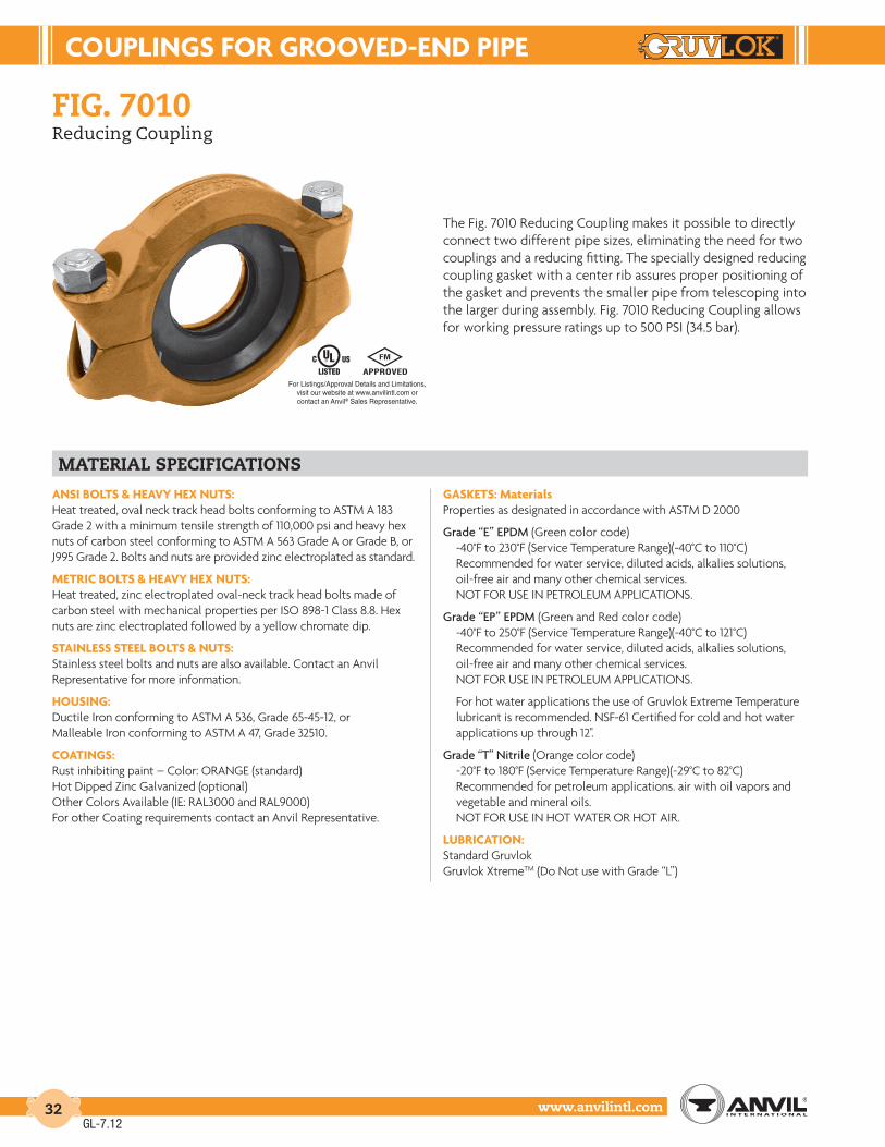
couPLInGS For GrooVEd-End PIPE
www.anvilintl.com32
fiG. 7010Reducing Coupling
The Fig. 7010 Reducing Coupling makes it possible to directly connect two different pipe sizes, eliminating the need for two couplings and a reducing fitting. The specially designed reducing coupling gasket with a center rib assures proper positioning of the gasket and prevents the smaller pipe from telescoping into the larger during assembly. Fig. 7010 Reducing Coupling allows for working pressure ratings up to 500 PSI (34.5 bar).
material specifications
AnSI BoLtS & HEAVY HEX nutS:Heat treated, oval neck track head bolts conforming to ASTM A 183 Grade 2 with a minimum tensile strength of 110,000 psi and heavy hex nuts of carbon steel conforming to ASTM A 563 Grade A or Grade B, or J995 Grade 2. Bolts and nuts are provided zinc electroplated as standard.
MEtrIc BoLtS & HEAVY HEX nutS:Heat treated, zinc electroplated oval-neck track head bolts made of carbon steel with mechanical properties per ISO 898-1 Class 8.8. Hex nuts are zinc electroplated followed by a yellow chromate dip.
StAInLESS StEEL BoLtS & nutS:Stainless steel bolts and nuts are also available. Contact an AnvilRepresentative for more information.
HouSInG:Ductile Iron conforming to ASTM A 536, Grade 65-45-12, orMalleable Iron conforming to ASTM A 47, Grade 32510.
coAtInGS:Rust inhibiting paint – Color: ORANGE (standard)Hot Dipped Zinc Galvanized (optional)Other Colors Available (IE: RAL3000 and RAL9000)For other Coating requirements contact an Anvil Representative.
GASKEtS: MaterialsProperties as designated in accordance with ASTM D 2000
Grade “E” EPDM (Green color code)-40°F to 230°F (Service Temperature Range)(-40°C to 110°C)Recommended for water service, diluted acids, alkalies solutions, oil-free air and many other chemical services.NOT FOR USE IN PETROLEUM APPLICATIONS.
Grade “EP” EPDM (Green and Red color code)-40°F to 250°F (Service Temperature Range)(-40°C to 121°C)Recommended for water service, diluted acids, alkalies solutions, oil-free air and many other chemical services.NOT FOR USE IN PETROLEUM APPLICATIONS.
For hot water applications the use of Gruvlok Extreme Temperature lubricant is recommended. NSF-61 Certified for cold and hot water applications up through 12".
Grade “T” Nitrile (Orange color code)-20°F to 180°F (Service Temperature Range)(-29°C to 82°C)Recommended for petroleum applications. air with oil vapors andvegetable and mineral oils.NOT FOR USE IN HOT WATER OR HOT AIR.
LuBrIcAtIon:Standard GruvlokGruvlok XtremeTM (Do Not use with Grade “L”)
GL-7.12
For Listings/Approval Details and Limitations,visit our website at www.anvilintl.com orcontact an Anvil® Sales Representative.

couPLInGS For GrooVEd-End PIPE
Intro
duct
ion
Coup
lings
Outle
tsFi
tting
sVa
lves
&
Acce
ssor
ies
High
Pres
sure
DI-L
OK®
Nipp
les
Plai
n-En
dFi
tting
sHD
PECo
uplin
gsSo
ck-It
®
Fitti
ngs
Stai
nles
sSt
eel M
etho
dRo
ll Gr
oove
rsIn
stal
latio
n&
Ass
embl
ySp
ecia
lCo
atin
gsDe
sign
Serv
ices
Tech
nica
lDa
taM
aste
r For
mat
3 Pa
rt Sp
ecs.
Pict
oria
lIn
dex
CTS
Copp
er
Syst
em
www.anvilintl.com 33
fiG. 7010Reducing Coupling
FIGurE 7010 rEducInG couPLInG
Nominal Size
Larger O.D.
Smaller O.D.
Max. Working Pressure
Max. End Load
Range of Pipe End
Separation
Deflection from CL Coupling Dimensions Coupling Bolts Specified Torque § Approx. Wt. Ea.Per Coupling of Pipe X Y Z Qty. Size Min. Max.
In./DN(mm) In./mm In./mm PSI/bar Lbs./kN In./mm Degrees(˚)-Minutes(') In./ft-mm/m In./mm In./mm In./mm In./mm Ft.-Lbs./N-m Lbs./Kg
2 x 11⁄2 2.375 1.900 500 2,215 0-1⁄32 0° 45' 0.16 35⁄8 57⁄8 17⁄8 2 1⁄2 x 23⁄4 80 100 2.050 x 40 60.3 48.3 34.5 9.85 0-0.79 13.1 92 149 48 M12 x 70 110 150 0.9
21⁄2 x 2 2.875 2.375 500 3,246 0-1⁄32 0° 37' 0.13 41⁄4 63⁄8 17⁄8 2 1⁄2 x 23⁄4 80 100 3.565 x 50 73.0 60.3 34.5 14.44 0-0.79 10.9 108 162 48 M12 x 70 110 150 1.6
3 x 2 3.500 2.375 500 4,811 0-1⁄32 0° 31' 0.11 47⁄8 71⁄8 17⁄8 2 1⁄2 x 23⁄4 80 100 4.480 x 50 88.9 60.3 34.5 21.40 0-0.79 8.9 124 181 48 M12 x 70 110 150 2.0
3 x 21⁄2 3.500 2.875 500 4,811 0-1⁄32 0° 31' 0.11 47⁄8 71⁄8 17⁄8 2 1⁄2 x 23⁄4 80 100 4.180 x 65 88.9 73.0 34.5 21.40 0-0.79 8.9 124 181 48 M12 x 70 110 150 1.9
4 x 2 4.500 2.375 500 7,952 0-3⁄32 1° 12' 0.25 61⁄4 87⁄8 2 2 5⁄8 x 31⁄2 100 130 8.9100 x 50 114.3 60.3 34.5 35.37 0-2.38 20.8 159 225 51 M16 x 85 135 175 4.0
4 x 21⁄2 4.500 2.875 500 7,952 0-3⁄32 1° 12' 0.25 61⁄4 87⁄8 2 2 5⁄8 x 31⁄2 100 130 7.9100 x 65 114.3 73.0 34.5 35.37 0-2.38 20.8 159 225 51 M16 x 85 135 175 3.6
4 x 3 4.500 3.500 500 7,952 0-3⁄32 1° 12' 0.25 61⁄4 87⁄8 2 2 5⁄8 x 31⁄2 100 130 6.7100 x 80 114.3 88.9 34.5 35.37 0-2.38 20.8 159 225 51 M16 x 85 135 175 3.0
5 x 4 5.563 4.500 500 12,153 0-3⁄32 1° 58' 0.20 71⁄4 105⁄8 21⁄8 2 3⁄4 x 41⁄2 130 180 11.4125 x 100 141.3 114.3 34.5 54.06 0-2.38 16.8 184 270 54 M20 x 110 175 245 5.2
6 x 4 6.625 4.500 500 17,236 0-3⁄32 0° 49' 0.17 81⁄4 115⁄8 21⁄8 2 3⁄4 x 41⁄2 130 180 13.4150 x 100 168.3 114.3 34.5 76.67 0-2.38 14.1 210 295 54 M20 x 110 175 245 6.1
6 x 5 6.625 5.562 500 17,236 0-3⁄32 0° 49' 0.17 81⁄2 115⁄8 21⁄8 2 3⁄4 x 41⁄2 130 180 13.5150 x 125 168.3 141.3 34.5 76.67 0-2.38 14.1 216 295 54 M20 x 110 175 245 6.1
8 x 6 8.625 6.625 500 29,213 0-3⁄32 0° 37' 0.13 101⁄2 14 21⁄4 2 3⁄4 x 41⁄2 130 180 17.7200 x 150 219.1 168.3 34.5 129.95 0-2.38 10.9 267 356 57 M20 x 110 175 245 8.0
Fig. 7010Coupling with Gasket
GL-6.11
NOTES:Fig. 7010 Reducing Coupling should not be used with end caps in systems where a vacuum may be developed. Contact your Anvil Representative for details.Range of Pipe End Separation and Angular Deflection values are for roll grooved pipe and may be doubled for cut groove pipe. See page 190 for details. Refer to page 196 for Misalignment & Deflection Calculations and page 197 for Curve Layout Calculations.
For additional details see “Coupling Data Chart Notes” on page 17.§ – For additional Bolt Torque information, see page 190.See Installation & Assembly directions on page 161.Not for use in copper systems.
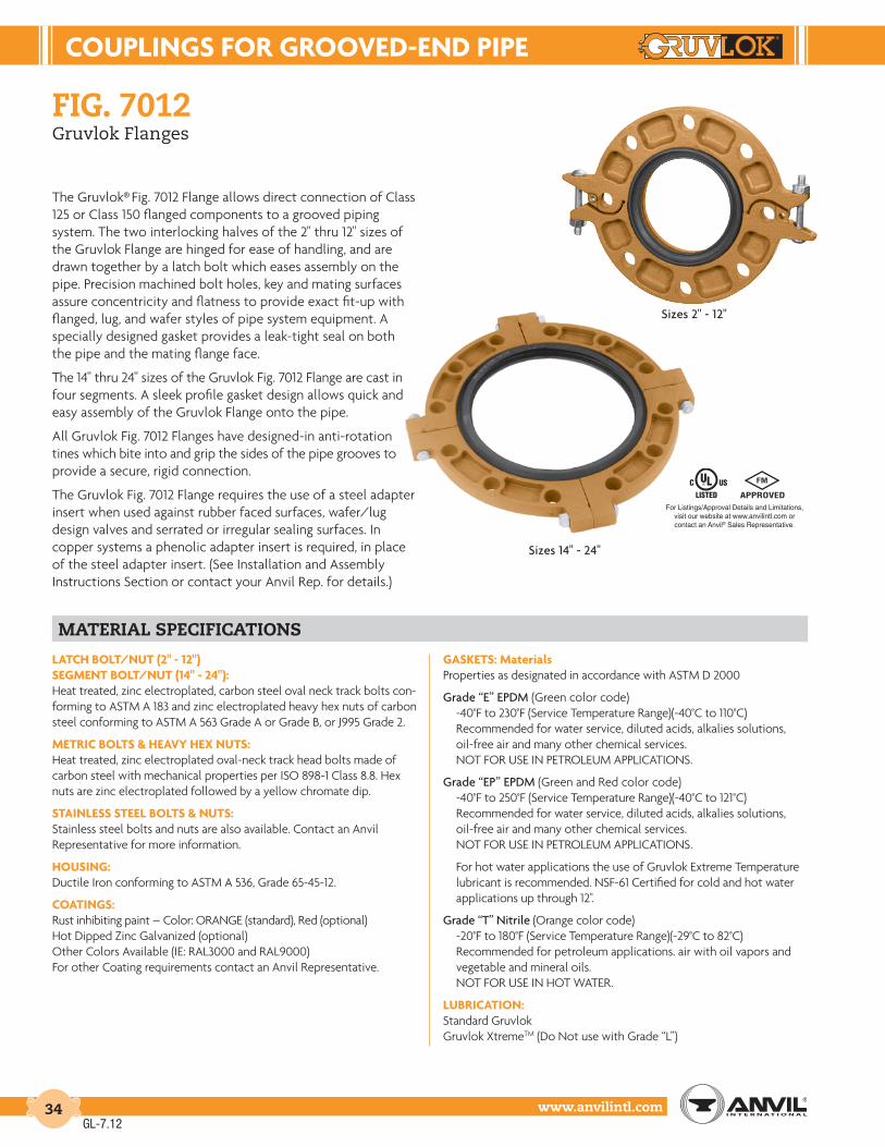
couPLInGS For GrooVEd-End PIPE
www.anvilintl.com34
fiG. 7012Gruvlok Flanges
The Gruvlok® Fig. 7012 Flange allows direct connection of Class 125 or Class 150 flanged components to a grooved piping system. The two interlocking halves of the 2" thru 12" sizes of the Gruvlok Flange are hinged for ease of handling, and are drawn together by a latch bolt which eases assembly on the pipe. Precision machined bolt holes, key and mating surfaces assure concentricity and flatness to provide exact fit-up with flanged, lug, and wafer styles of pipe system equipment. A specially designed gasket provides a leak-tight seal on both the pipe and the mating flange face.
The 14" thru 24" sizes of the Gruvlok Fig. 7012 Flange are cast in four segments. A sleek profile gasket design allows quick and easy assembly of the Gruvlok Flange onto the pipe.
All Gruvlok Fig. 7012 Flanges have designed-in anti-rotation tines which bite into and grip the sides of the pipe grooves to provide a secure, rigid connection.
The Gruvlok Fig. 7012 Flange requires the use of a steel adapter insert when used against rubber faced surfaces, wafer/lug design valves and serrated or irregular sealing surfaces. In copper systems a phenolic adapter insert is required, in place of the steel adapter insert. (See Installation and Assembly Instructions Section or contact your Anvil Rep. for details.)
material specifications
LAtcH BoLt/nut (2" - 12") SEGMEnt BoLt/nut (14" - 24"):Heat treated, zinc electroplated, carbon steel oval neck track bolts con-forming to ASTM A 183 and zinc electroplated heavy hex nuts of carbon steel conforming to ASTM A 563 Grade A or Grade B, or J995 Grade 2.
MEtrIc BoLtS & HEAVY HEX nutS:Heat treated, zinc electroplated oval-neck track head bolts made of carbon steel with mechanical properties per ISO 898-1 Class 8.8. Hex nuts are zinc electroplated followed by a yellow chromate dip.
StAInLESS StEEL BoLtS & nutS:Stainless steel bolts and nuts are also available. Contact an AnvilRepresentative for more information.
HouSInG:Ductile Iron conforming to ASTM A 536, Grade 65-45-12.
coAtInGS:Rust inhibiting paint – Color: ORANGE (standard), Red (optional)Hot Dipped Zinc Galvanized (optional)Other Colors Available (IE: RAL3000 and RAL9000)For other Coating requirements contact an Anvil Representative.
GASKEtS: MaterialsProperties as designated in accordance with ASTM D 2000
Grade “E” EPDM (Green color code)-40°F to 230°F (Service Temperature Range)(-40°C to 110°C)Recommended for water service, diluted acids, alkalies solutions, oil-free air and many other chemical services.NOT FOR USE IN PETROLEUM APPLICATIONS.
Grade “EP” EPDM (Green and Red color code)-40°F to 250°F (Service Temperature Range)(-40°C to 121°C)Recommended for water service, diluted acids, alkalies solutions, oil-free air and many other chemical services.NOT FOR USE IN PETROLEUM APPLICATIONS.
For hot water applications the use of Gruvlok Extreme Temperature lubricant is recommended. NSF-61 Certified for cold and hot water applications up through 12".
Grade “T” Nitrile (Orange color code)-20°F to 180°F (Service Temperature Range)(-29°C to 82°C)Recommended for petroleum applications. air with oil vapors and vegetable and mineral oils.NOT FOR USE IN HOT WATER.
LuBrIcAtIon:Standard GruvlokGruvlok XtremeTM (Do Not use with Grade “L”)
Sizes 2" - 12"
Sizes 14" - 24"
GL-7.12
For Listings/Approval Details and Limitations,visit our website at www.anvilintl.com orcontact an Anvil® Sales Representative.

couPLInGS For GrooVEd-End PIPE
Intro
duct
ion
Coup
lings
Outle
tsFi
tting
sVa
lves
&
Acce
ssor
ies
High
Pres
sure
DI-L
OK®
Nipp
les
Plai
n-En
dFi
tting
sHD
PECo
uplin
gsSo
ck-It
®
Fitti
ngs
Stai
nles
sSt
eel M
etho
dRo
ll Gr
oove
rsIn
stal
latio
n&
Ass
embl
ySp
ecia
lCo
atin
gsDe
sign
Serv
ices
Tech
nica
lDa
taM
aste
r For
mat
3 Pa
rt Sp
ecs.
Pict
oria
lIn
dex
CTS
Copp
er
Syst
em
www.anvilintl.com 35
fiG. 7012Gruvlok Flanges
2"-12" sizes 14"-24" sizes
GruVLoK FIGurE 7012 FLAnGE: AnSI cLASS 150 or ISo Pn10 or Pn16 BoLt PAttErnS
Nominal Size O.D.
Max. Working
Pressure▼
Max. End Load▼
Latch Bolt Dimensions Sealing Surface Mating Flange BoltsApprox. Wt. Ea.Latch Bolt Size*
Specified Torque §X Y Z A Max. B Min.
Mating Flange Bolts Bolt Circle Diameter
Bolt Hole Diameter
Specified Torque §
Min. Max. Qty. ANSI Size (ANSI) Min. Max.
In./DN(mm) In./mm PSI/bar Lbs./kN In./mm Ft.-Lbs/N-m In./mm In./mm In./mm In./mm In./mm PN10 (16) in. (ISO) mm In./mm In./mm Ft.-Lbs/N-m Lbs./Kg
2 2.375 300 1,329 3⁄8 x 23⁄4 30 45 61⁄4 83⁄8 3⁄4 23⁄8 37⁄16 4 5⁄8 x 23⁄4 43⁄4 3⁄4 110 140 4.250 60.3 20.7 5.91 M10 x 70 40 60 159 213 19 60 87 4 M16 x 70 120.7 19.1 149 190 1.9
21⁄2 2.875 300 1,948 3⁄8 x 23⁄4 30 45 7 91⁄2 3⁄4 27⁄8 4 4 5⁄8 x 23⁄4 51⁄2 3⁄4 110 140 4.665 73.0 20.7 8.66 M10 x 70 40 60 178 241 19 73 102 - M16 x 70 139.7 19.1 149 190 2.1
3 O.D. 2.996 300 2,115 - 30 45 7 1⁄4 9 3⁄4 3⁄4 3 4 1⁄8 - - - - 110 140 4.8
76.1 76.1 20.7 9.41 M10 x 70 40 60 184 248 19 76 105 4 M16 x 70 - - 149 190 2.23 3.500 300 2,886 3⁄8 x 23⁄4 30 45 77⁄8 101⁄2 3⁄4 31⁄2 49⁄16 4 5⁄8 x 23⁄4 6 3⁄4 110 140 6.0
88.9 88.9 20.7 12.84 M10 x 70 40 60 200 267 19 89 116 8 M16 x 70 152.4 19.1 149 190 2.7
4 4.500 300 4,771 3⁄8 x 23⁄4 30 45 9 111⁄2 3⁄4 41⁄2 59⁄16 8 5⁄8 x 23⁄4 71⁄2 3⁄4 110 140 6.3100 114.3 20.7 21.22 M10 x 70 40 60 229 292 19 114 141 8 M16 x 70 190.5 19.1 149 190 2.9
51⁄2 O.D. 5.500 300 7,127 - 30 45 9 7⁄8 12 7⁄8 7⁄8 5 9⁄16 6 3⁄4 - - - - 220 250 15.6
139.7 139.7 20.7 31.70 M10 x 70 40 60 251 327 22 141 171 8 M16 x 75 - - 298 339 7.15 5.563 300 7,292 3⁄8 x 23⁄4 30 45 10 121⁄2 7⁄8 59⁄16 63⁄4 8 3⁄4 x 27⁄8 81⁄2 7⁄8 220 250 8.8
125 141.3 20.7 32.44 M10 x 70 40 60 254 318 22 141 171 - - 215.9 22.2 298 339 4.0
61⁄2 O.D. 6.500 300 9,955 - 30 45 111⁄4 14 7⁄8 6 5⁄8 7 13⁄16 - - - - 220 250 9.7
165.1 165.1 20.7 44.28 M10 x 70 40 60 286 356 22 168 198 8 M20 x 80 - - 298 339 4.46 6.625 300 10,341 3⁄8 x 23⁄4 30 45 11 14 7⁄8 65⁄8 713⁄16 8 3⁄4 x 31⁄8 91⁄2 7⁄8 220 250 9.6
150 168.3 20.7 46.00 M10 x 70 40 60 279 356 22 168 198 8 M20 x 80 241.1 22.2 298 339 4.4
8 8.625 300 17,528 3⁄8 x 23⁄4 30 45 131⁄2 161⁄2 1 85⁄8 10 8 3⁄4 x 31⁄4 113⁄4 7⁄8 220 250 15.6200 219.1 20.7 77.97 M10 x 70 40 60 343 419 25 219 254 8 (12) M20 x 80 298.5 22.2 298 339 7.1
10 10.750 300 27,229 3⁄8 x 23⁄4 30 45 16 19 1 103⁄4 121⁄8 12 7⁄8 x 31⁄2 141⁄4 1 320 400 18.2250 273.1 20.7 121.12 M10 x 70 40 60 406 483 25 273 308 12 M20 x 90 362.0 25.4 439 542 8.3
12 12.750 300 38,303 3⁄8 x 23⁄4 30 45 19 213⁄4 11⁄4 123⁄4 141⁄8 12 7⁄8 x 33⁄4 17 1 320 400 29.9300 323.9 20.7 170.38 M10 x 70 40 60 483 552 32 324 359 12 - 431.8 25.4 439 542 13.6
12 (PN) 12.750 300 38,303 - 30 45 18 1⁄8 21 1⁄4 1 12 3⁄4 14 1⁄8 12 - - - 320 400 20.9
300 323.9 20.7 170.38 M10 x 70 40 60 460 540 25 324 359 12 M20 x 90 ✛ - - 439 542 9.514 14.000 300 46,181 5⁄8 x 41⁄4 100 130 21 24 11⁄2 14 16 12 1 x 41⁄4 183⁄4 11⁄8 360 520 52.5350 355.6 20.7 205.43 - 136 176 533 610 38 356 406 - - 476.3 28.6 488 705 23.8
16 16.000 300 60,319 5⁄8 x 41⁄4 100 130 231⁄2 261⁄2 11⁄2 16 18 16 1 x 41⁄4 211⁄4 11⁄8 360 520 67.0400 406.4 20.7 268.31 - 136 176 597 673 38 406 457 - - 539.8 28.6 488 705 30.4
18 18.000 300 76,341 3⁄4 x 5 130 180 25 29 15⁄8 18 20 16 11⁄8 x 43⁄4 223⁄4 11⁄4 450 725 82.5450 457.2 20.7 339.58 - 176 244 635 737 41 457 508 - – 577.9 31.8 610 983 37.4
20 20.000 300 94,248 3⁄4 x 5 130 180 271⁄2 311⁄2 13⁄4 20 22 20 11⁄8 x 43⁄4 25 11⁄4 450 725 106.5500 508.0 20.7 419.23 - 176 244 699 800 44 508 559 - – 635.0 31.8 610 983 48.3
24 24.000 250 113,097 7⁄8 x 51⁄2 180 220 32 361⁄2 17⁄8 24 26 20 11⁄4 x 51⁄2 291⁄2 13⁄8 620 1,000 138.5600 609.6 17.2 503.08 - 244 298 813 927 48 610 660 - - 749.3 34.92 841 1,356 62.8
Mating Flange
GL-6.11
NOTES:The Gruvlok Flange bolt hole pattern conforms to ANSI Class 150 and Class 125 flanges.To avoid interference issues, flanges cannot be assembled directly to Series 7700 butterfly valve. Flange can be assembled to one side of series 7500 and 7600 valve only.Mating flange bolts must be at least Intermediate Strength Bolting per ASME B16.5. Bolts with material properties equal or greater than SAE J429 Grade 5 are acceptable.Refer to Gruvlok Products Catalog or Anvil’s web site for more information on installing this flange.
For additional details see “Coupling Data Chart Notes” on page 17.+ PN 16 uses M24 x 90 (PN) Dimensions for bolt circle PN 10 & 16 Flange.* Available in ANSI or metric bolt sizes only as indicated.▼ Based on use with standard wall pipe.§ – For additional Bolt Torque information, see page 190.See Installation & Assembly directions on page 162-163.

couPLInGS For GrooVEd-End PIPE
www.anvilintl.com36
fiG. 7012Gruvlok Flanges
A. The sealing surfaces A Max. to B Min. of the mating flange must be free from gouges, undulations and deformities of any type to ensure proper sealing of the gasket.
B. Gruvlok Flanges are to be assembled on butterfly valves so as not to interfere with actuator or handle operation.
C. Do not use Gruvlok Flanges within 90 degrees of one another on standard fittings because the outside dimensions may cause interference.
D. Gruvlok Flanges should not be used as anchor points for tierods across non-restrained joints.
E. Fig. 7012 Gruvlok Flange sealing gaskets require a hard flat surface for adequate sealing. The use of a Gruvlok Flange Adapter Insert is required for applications against rubber faced valves or other equipment. The Gruvlok Flange Adapter Insert is installed between the Gruvlok Flange sealing gasket and the mating flange or surface to provide a good sealing surface area.
F. Gruvlok Flanges are not recommended for use against formed rubber flanges.
G. Contact an Anvil Representative for Di-Electric Flange connections.
Applications which require a Gruvlok Flange Adapter Insert:
1. When mating to a wafer valve (lug valve), if the valve is rubber faced in the area designated by the sealing surface dimensions (A Max. to B Min.), place the Gruvlok Flange Adapter Insert between the valve and the Gruvlok flange.
2. When mating to a rubber-faced metal flange, the Gruvlok Flange Adapter Insert is placed between the Gruvlok Flange and the rubber-faced flange.
3. When mating to a serrated flange surface, a standard full-faced flange gasket is installed against the serrated flange face and the Gruvlok Flange Adapter Insert is placed between the Gruvlok Flange and the standard Flange gasket.
4. When mating to valves or other component equipment where the flange face has an insert, use procedure described in note 3.
Rubber Su r fac e
Mating Flange Component with Serrated Face
Mating Flange Gruvlok Figure 7012 Flange
B min. A max.
Grooved Pipe Flange Adapter Insert Flange Adapter Insert
Flange Gasket
Gruvlok Figure 7012 Flange
Grooved Pipe
Mating Flange
GL-7.12

couPLInGS For GrooVEd-End PIPE
Intro
duct
ion
Coup
lings
Outle
tsFi
tting
sVa
lves
&
Acce
ssor
ies
High
Pres
sure
DI-L
OK®
Nipp
les
Plai
n-En
dFi
tting
sHD
PECo
uplin
gsSo
ck-It
®
Fitti
ngs
Stai
nles
sSt
eel M
etho
dRo
ll Gr
oove
rsIn
stal
latio
n&
Ass
embl
ySp
ecia
lCo
atin
gsDe
sign
Serv
ices
Tech
nica
lDa
taM
aste
r For
mat
3 Pa
rt Sp
ecs.
Pict
oria
lIn
dex
CTS
Copp
er
Syst
em
www.anvilintl.com 37
fiG. 7013Gruvlok Flanges (300# Flange)
The Gruvlok Fig. 7013 300# Flange allows direct connection of Class 250 or Class 300 flanged components to a Gruvlok piping system. The two halves of the 2" thru 12" sizes of both Gruvlok Flanges are drawn together by a latch bolt which eases assembly on the pipe. A specially designed gasket provides a leak-tight seal on both the pipe and the mating flange face.
Gruvlok Flanges have designed-in anti-rotation tines which bite into and grip the side of the pipe groove to provide a secure, rigid connection.
Gruvlok flange adapter insert required when mating to rubber surfaces or serrated faced mating flanges.
* the 7013 Gruvlok adapter flange should not be used with the 78FP or 7800 check valve.
material specifications
AnSI BoLtS & HEAVY HEX nutS:Heat treated, oval neck track head bolts conforming to ASTM A 183 Grade 2 with a minimum tensile strength of 110,000 psi and heavy hex nuts of carbon steel conforming to ASTM A 563 Grade A or Grade B, or J995 Grade 2. Bolts and nuts are provided zinc electroplated as standard.
MEtrIc BoLtS & HEAVY HEX nutS:Heat treated, zinc electroplated oval-neck track head bolts made of carbon steel with mechanical properties per ISO 898-1 Class 8.8. Hex nuts are zinc electroplated followed by a yellow chromate dip.
StAInLESS StEEL BoLtS & nutS:Stainless steel bolts and nuts are also available. Contact an AnvilRepresentative for more information.
HouSInG:Ductile Iron conforming to ASTM A 536, Grade 65-45-12.
coAtInGS:Rust inhibiting paint – Color: ORANGE (standard)Hot Dipped Zinc Galvanized (optional)Other Colors Available (IE: RAL3000 and RAL9000)For other Coating requirements contact an Anvil Representative.
GASKEtS: MaterialsProperties as designated in accordance with ASTM D 2000
Grade “E” EPDM (Green color code)-40°F to 230°F (Service Temperature Range)(-40°C to 110°C)Recommended for water service, diluted acids, alkalies solutions, oil-free air and many other chemical services.NOT FOR USE IN PETROLEUM APPLICATIONS.
Grade “EP” EPDM (Green and Red color code)-40°F to 250°F (Service Temperature Range)(-40°C to 121°C)Recommended for water service, diluted acids, alkalies solutions, oil-free air and many other chemical services.NOT FOR USE IN PETROLEUM APPLICATIONS.
For hot water applications the use of Gruvlok Extreme Temperature lubricant is recommended. NSF-61 Certified for cold and hot water applications up through 12".
Grade “T” Nitrile (Orange color code)-20°F to 180°F (Service Temperature Range)(-29°C to 82°C)Recommended for petroleum applications. air with oil vapors and vegetable and mineral oils.NOT FOR USE IN HOT WATER OR HOT AIR.
LuBrIcAtIon:Standard GruvlokGruvlok XtremeTM (Do Not use for Grade “L”)
GL-7.12
For Listings/Approval Details and Limitations,visit our website at www.anvilintl.com orcontact an Anvil® Sales Representative.

couPLInGS For GrooVEd-End PIPE
www.anvilintl.com38
fiG. 7013Gruvlok Flanges (300# Flange)
GruVLoK FIGurE 7013 FLAnGE: AnSI cLASS 250 And 300 BoLt PAttErn
Nominal Size O.D.
Max. Wk. Pressure
▼
Max. End Load ▼
Latch* Bolt Size
Specified Torque § Dimensions Sealing Surface Mating Flange Bolts Approx. Wt. Ea.Min. Max. X Y Z A Max. B Min. Qty. ANSI Size (ANSI) in. Bolt Circle Dia. Bolt Hole Dia.
In./DN(mm) In./mm PSI/bar Lbs./kN In. Ft.-Lbs/N-m In./mm In./mm In./mm In./mm In./mm (ISO) mm In./mm In./mm Lbs./Kg
2 2.375 750 3,323 3⁄8 x 21⁄2 30 45 61⁄2 8 1 23⁄8 37⁄16 8 5⁄8 x 3 5 3⁄4 5.050 60.3 51.7 14.78 - - - 165 203 25 60 87 - - 127.0 19.1 2.3
21⁄2 2.875 750 4,869 3⁄8 x 21⁄2 30 45 71⁄2 91⁄8 1 27⁄8 4 8 3⁄4 x 31⁄4 57⁄8 7⁄8 6.965 73.0 51.7 21.66 - - - 191 232 25 73 102 - - 149.2 22.2 3.1
3 3.500 750 7,216 3⁄8 x 21⁄2 30 45 81⁄4 97⁄8 11⁄8 31⁄2 49⁄16 8 3⁄4 x 31⁄2 65⁄8 7⁄8 9.480 88.9 51.7 32.10 - - - 210 251 29 89 116 - - 168.3 22.2 4.3
4 4.500 750 11,928 3⁄8 x 21⁄2 30 45 10 113⁄8 11⁄4 41⁄2 55⁄8 8 3⁄4 x 33⁄4 77⁄8 7⁄8 14.4100 114.3 51.7 53.06 - - - 254 289 32 114 143 - - 200.0 22.2 6.5
5 5.563 750 18,229 3⁄8 x 21⁄2 30 45 11 125⁄8 13⁄8 59⁄16 63⁄4 8 3⁄4 x 41⁄2 91⁄4 7⁄8 18.3125 141.3 51.7 81.09 - - - 279 321 35 141 171 - - 235.0 22.2 8.3
6 6.625 750 25,854 3⁄8 x 21⁄2 30 45 121⁄2 141⁄8 11⁄2 65⁄8 713⁄16 12 3⁄4 x 41⁄2 105⁄8 7⁄8 24.9150 168.3 51.7 115.00 - - - 318 359 38 168 198 - - 269.9 22.2 11.3
8 8.625 750 43,820 1⁄2 x 31⁄2 80 100 15 167⁄8 15⁄8 85⁄8 10 12 7⁄8 x 43⁄4 13 1 35.4200 219.1 51.7 194.92 - - - 381 429 41 219 254 - - 330.2 25.4 16.1
10 10.750 750 68,072 1⁄2 x 31⁄2 80 100 171⁄2 193⁄8 17⁄8 103⁄4 121⁄8 16 1 x 5 151⁄4 11⁄8 54.0250 273.1 51.7 302.80 - - - 445 492 48 273 308 - - 387.4 28.6 24.5
12 12.750 750 95,757 1⁄2 x 31⁄2 80 100 201⁄2 221⁄2 2 123⁄4 143⁄16 16 11⁄8 x 53⁄4 173⁄4 11⁄4 74.8300 323.9 51.7 425.95 - - - 521 572 51 324 360 - - 450.9 31.8 33.9
XY Z
Mating Flange
GL-7.12
NOTES:Effective sealing area of mating flange must be free from gouges, undulations or deformities of any type to ensure proper sealing of the gasket.Flange cannot be assembled directly to Series 7700 butterfly valve. Flange can be assembled to one side of series 7500 and 7600 valve.
For additional details see “Coupling Data Chart Notes” on page 17.* Available in ANSI or metric bolt sizes only as indicated.▼ Based on use with standard wall pipe.§ – For additional Bolt Torque information, see page 190.See Installation & Assembly directions or contact your Anvil RepresentativeNot for use with copper systems.

couPLInGS For GrooVEd-End PIPE
Intro
duct
ion
Coup
lings
Outle
tsFi
tting
sVa
lves
&
Acce
ssor
ies
High
Pres
sure
DI-L
OK®
Nipp
les
Plai
n-En
dFi
tting
sHD
PECo
uplin
gsSo
ck-It
®
Fitti
ngs
Stai
nles
sSt
eel M
etho
dRo
ll Gr
oove
rsIn
stal
latio
n&
Ass
embl
ySp
ecia
lCo
atin
gsDe
sign
Serv
ices
Tech
nica
lDa
taM
aste
r For
mat
3 Pa
rt Sp
ecs.
Pict
oria
lIn
dex
CTS
Copp
er
Syst
em
www.anvilintl.com 39
fiG. 7013Gruvlok Flanges (300# Flange)
A. The sealing surfaces A Max. to B Min. of the mating flange must be free from gouges, undulations and deformities of any type to ensure proper sealing of the gasket.
B. Gruvlok Flanges are to be assembled on butterfly valves so as not to interfere with actuator or handle operation.
C. Do not use Gruvlok Flanges within 90 degrees of one another on standard fittings because the outside dimensions may cause interference.
D. Gruvlok Flanges should not be used as anchor points for tierods across non-restrained joints.
E. Fig. 7013 Gruvlok Flange sealing gaskets require a hard flat surface for adequate sealing. The use of a Gruvlok Flange Adapter Insert is required for applications against rubber faced valves or other equipment. The Gruvlok Flange Adapter Insert is installed between the Gruvlok Flange sealing gasket and the mating flange or surface to provide a good sealing surface area.
F. Gruvlok Flanges are not recommended for use against formed rubber flanges.
G. Contact an Anvil Representative for Di-Electric Flange connections.
Applications which require a Gruvlok Flange Adapter Insert:
1. When mating to a wafer valve (lug valve), if the valve is rubber faced in the area designated by the sealing surface dimensions (A Max. to B Min.), place the Gruvlok Flange Adapter Insert between the valve and the Gruvlok flange.
2. When mating to a rubber-faced metal flange, the Gruvlok Flange Adapter Insert is placed between the Gruvlok Flange and the rubber-faced flange.
3. When mating to a serrated flange surface, a standard fullfaced flange gasket is installed against the serrated flange face and the Gruvlok Flange Adapter Insert is placed between the Gruvlok Flange and the standard Flange gasket.
4. When mating to valves or other component equipment where the flange face has an insert, use procedure described in note 3.
Rubber Surface
Gruvlok Figure 7013 Flange
B min.A max.
Grooved Pipe Gruvlok Flange Adapter Insert Gruvlok Flange Adapter Insert
Flange Gasket
Gruvlok Figure 7013 Flange
Grooved Pipe
Mating Flange Component
Serrated Face Mating Flange
Mating Flange
GL-7.12

couPLInGS For GrooVEd-End PIPE
www.anvilintl.com40
NIPPLE COUPLING END ADAPTER
L
GR
UV
LOK
4'
' FI
G.
7000
GR
UV
LOK
4'
' FI
G.
7000
GR
UV
LOK
4'
' FI
G.
7000
GR
UV
LOK
4'
' FI
G.
7000
GR
UV
LOK
4'
' FI
G.
7000
fiG. 7240Expansion Joints
The Gruvlok® Figure 7240 Expansion Joints take advantage of the axial expansion capabilities of the Gruvlok flexible couplings to produce a reliable grooved end expansion joint. The expansion joints are comprised of the Gruvlok Figure 7000 or 7001 flexible couplings and precision machined grooved end pipe nipples. Ties are used to custom preset the expansion joints in the expanded, compressed or intermediate position to provide for the desired expansion and/or contraction compensation.
Installation is easy, simply follow the Gruvlok coupling installation and assembly instructions to install the expansion joint in the system and after installation is complete, remove the ties.
The expansion joints can be used as flexible connectors, however, they will not simultaneously provide for full axial expansion and angular deflection. Expansion joints require pipe anchoring capable of restraining the maximum system pressure end load.
The service conditions are the same as the service conditions for coupling and gasket used in the expansions joint. Unless otherwise requested, this product will contain a silicone based lubricant. Refer to the Gruvlok catalog for coupling performance capabilities and material specifications. To order please provide the order form on the page 213.
NOTE: The Gruvlok Figure 7240 Expansion Joint is also available in stainless steel for use in grooved copper systems.
NOTE: Expansion joint shown with shipping support. Contact an Anvil representative for proper installation support requirements.
FIGurE 7240 PErForMAncE dAtA (IncHES)
Nominal Size O.D. Coupling
Figure X Y Compressed Length L
Expanded Length L
Coupling Movement Capability
Number of Couplings
Total Movement Capability
In./DN(mm) In./mm In./mm In./mm In./mm In./mm In./mm In./mm
2 2.375 7000 31⁄2 51⁄2 30 311⁄4 1⁄8 10 11⁄450 60.3 89 125 762 794 3.2 31.821⁄2 2.875 7000 4 53⁄4 30 311⁄4 1⁄8 10 11⁄465 73.0 100 146 762 794 3.2 31.83 3.500 7000 45⁄8 63⁄4 30 311⁄4 1⁄8 10 11⁄480 88.9 117 171 762 794 3.2 31.84 4.500 7000 57⁄8 81⁄8 171⁄2 183⁄4 1⁄4 5 11⁄4
100 114.3 149 206 445 476 6.4 31.85 5.562 7000 7 95⁄8 19 201⁄4 1⁄4 5 11⁄4
125 141.3 178 244 483 514 6.4 31.86 6.625 7000 8 11 19 201⁄4 1⁄4 5 11⁄4
150 168.3 200 279 483 514 6.4 31.88 8.625 7000 103⁄8 131⁄4 221⁄2 233⁄4 1⁄4 5 11⁄4
200 219.0 264 337 572 603 6.4 31.810 10.750 7001 127⁄8 171⁄2 231⁄2 243⁄4 1⁄4 5 11⁄4250 273.1 327 445 597 629 6.4 31.812 12.750 7001 15 191⁄2 231⁄2 243⁄4 1⁄4 5 11⁄4300 323.9 381 495 597 629 6.4 31.8
X
Y
GL-7.12

couPLInGS For GrooVEd-End PIPE
Intro
duct
ion
Coup
lings
Outle
tsFi
tting
sVa
lves
&
Acce
ssor
ies
High
Pres
sure
DI-L
OK®
Nipp
les
Plai
n-En
dFi
tting
sHD
PECo
uplin
gsSo
ck-It
®
Fitti
ngs
Stai
nles
sSt
eel M
etho
dRo
ll Gr
oove
rsIn
stal
latio
n&
Ass
embl
ySp
ecia
lCo
atin
gsDe
sign
Serv
ices
Tech
nica
lDa
taM
aste
r For
mat
3 Pa
rt Sp
ecs.
Pict
oria
lIn
dex
CTS
Copp
er
Syst
em
www.anvilintl.com 41
fiG. 7240Expansion Joints
hanGer details
AnchorAnchor
Existing Piping System Existing Piping System
Guide Guide
Guide
Anchor
vertical support horizontal support
Grooved Connection toExisting Piping System
Existing Piping System
Gruvlok Fig. 7240 ExpansionJoint and Trough Hanger
Existing Piping System
Grooved Connection toExisting Piping System
trough and hanger
GL-6.11

BrAncH outLEtS
www.anvilintl.com42
fiG. 7042Outlet Coupling
The Gruvlok Fig. 7042 Outlet Coupling is designed to join two sections of grooved end pipe and form a reducing outlet connection. The outlet couplings are available for the 1 1⁄2" through 6" IPS or ISO run pipe sizes with the outlet pipe sizes ranging from 1⁄2" through 2".
Assembly of the coupling will create a gap between the pipe ends allowing the space required for the introduction of an outlet connection. The outlet connections are available grooved (Fig. 7042G), FPT (Fig. 7042F) and MPT (Fig. 7042M).
The gaskets are available in EPDM and Nitrile to suit a wide range of applications. The gasket design is a unique pressure responsive design that provides a higher sealing force as pressure is increased. The outlet gasket seal is reinforced by a steel ring and is mated to a machined housing surface to assure a leak-tight outlet seal. Center ribs inside the gasket ease positioning of the pipe during installation and provide additional support to the gasket. The outlet couplings are NOT recommended for vacuum applications.
material specifications
AnSI BoLtS & HEAVY HEX nutS:Heat treated, oval neck track head bolts conforming to ASTM A 183 Grade 2 with a minimum tensile strength of 110,000 psi and heavy hex nuts of carbon steel conforming to ASTM A 563 Grade A or Grade B, or J995 Grade 2. Bolts and nuts are provided zinc electroplated as standard.
MEtrIc BoLtS & HEAVY HEX nutS:Heat treated, zinc electroplated oval-neck track head bolts made of carbon steel with mechanical properties per ISO 898-1 Class 8.8. Hex nuts are zinc electroplated followed by a yellow chromate dip.
StAInLESS StEEL BoLtS & nutS:Stainless steel bolts and nuts are also available. Contact an AnvilRepresentative for more information.
HouSInG:Ductile Iron conforming to ASTM A 536, Grade 65-45-12.
coAtInGS:Rust inhibiting paint – Color: ORANGE (standard)Hot Dipped Zinc Galvanized (optional)Other Colors Available (IE: RAL3000 and RAL9000)For other Coating requirements contact an Anvil Representative.
GASKEtS: MaterialsProperties as designated in accordance with ASTM D 2000
Grade “E” EPDM (Green color code)-40°F to 150°F (Service Temperature Range)(-40°C to 66°C)Recommended for water service, diluted acids, alkalies solutions, oil-free air and many other chemical services.NOT FOR USE IN PETROLEUM APPLICATIONS.
Grade “T” Nitrile (Orange color code)-20°F to 150°F (Service Temperature Range)(-29°C to 66°C)Recommended for petroleum applications. air with oil vapor and vegetable and mineral oils.NOT FOR USE IN HOT WATER OR HOT AIR.
LuBrIcAtIon:Standard GruvlokGruvlok XtremeTM(Do Not use with Grade “L”)
The Figure 7074 Cast Caps are NOT recommended for use on run connections. Figure 7075 Bull Plugs must be used on end of line run connections. Figure 7074 Cast Caps may be used on Figure 7042G outlet connections. Flow into the outlet connection of the Figure 7042 Outlet Couplings must not exceed 7 ft./sec.
GL-7.12

BrAncH outLEtS
Intro
duct
ion
Coup
lings
Outle
tsFi
tting
sVa
lves
&
Acce
ssor
ies
High
Pres
sure
DI-L
OK®
Nipp
les
Plai
n-En
dFi
tting
sHD
PECo
uplin
gsSo
ck-It
®
Fitti
ngs
Stai
nles
sSt
eel M
etho
dRo
ll Gr
oove
rsIn
stal
latio
n&
Ass
embl
ySp
ecia
lCo
atin
gsDe
sign
Serv
ices
Tech
nica
lDa
taM
aste
r For
mat
3 Pa
rt Sp
ecs.
Pict
oria
lIn
dex
CTS
Copp
er
Syst
em
www.anvilintl.com 43
fiG. 7042Outlet Coupling
Female IPS Outlet- 7042F Male IPS Outlet - 7042M Grooved Outlet - 7042G
FIGurE 7042 - outLEt couPLInG
Nominal Pipe SizeWorking Pressure
Max. Run End Load
Range of Pipe End Separation
Coupling DimensionsBolt Size Approx .
Wt. Each RunOutlet
X Y Z FPT F MPT M Grv. GFPT F MPT/Grv. M/G
In./DN(mm) In./mm In./mm PSI/bar Lbs./kN In./mm In./mm In./mm In./mm In./mm In./mm In./mm In./mm Lbs./Kg
11⁄240
1⁄2 — 500 1418 3⁄4-11⁄16 215⁄16 43⁄4 23⁄4 21⁄16 — — 3⁄8 x 21⁄8 2.615 — 34.5 6.31 19-27 75 121 70 52 — — - 1.23⁄4 — 500 1418 3⁄4-11⁄16 215⁄16 43⁄4 23⁄4 21⁄16 — — 3⁄8 x 21⁄8 2.620 — 34.5 6.31 19-27 75 121 70 52 — — - 1.2
1 — 500 1418 3⁄4-11⁄16 215⁄16 43⁄4 23⁄4 115⁄16 — — 3⁄8 x 21⁄8 2.925 — 34.5 6.31 19-27 75 121 70 49 — — - 1.3
250
1⁄2 — 500 2215 11⁄16-1 37⁄16 51⁄4 23⁄4 25⁄16 — — 3⁄8 x 21⁄8 3.115 — 34.5 9.85 17-25 87 133 70 59 — — - 1.43⁄4 — 500 2215 11⁄16-1 37⁄16 51⁄4 23⁄4 25⁄16 — — 3⁄8 x 21⁄8 3.120 — 34.5 9.85 17-25 87 133 70 59 — — - 1.4
1 1 500 2215 11⁄16-1 37⁄16 51⁄4 23⁄4 23⁄16 27⁄8 31⁄2 3⁄8 x 21⁄8 3.325 25 34.5 9.85 17-25 87 133 70 56 73 89 - 1.5
21⁄265
1⁄2 — 500 3246 13⁄16-11⁄2 43⁄16 61⁄2 31⁄4 29⁄16 — — 1⁄2 x 23⁄8 4.815 — 34.5 14.44 30-38 106 165 83 65 — — - 2.23⁄4 — 500 3246 13⁄16-11⁄2 43⁄16 61⁄2 31⁄4 29⁄16 — — 1⁄2 x 23⁄8 4.620 — 34.5 14.44 30-38 106 165 83 65 — — - 2.1
1 — 500 3246 13⁄16-11⁄2 43⁄16 61⁄2 31⁄4 27⁄16 — — 1⁄2 x 23⁄8 4.425 — 34.5 14.44 30-38 106 165 83 62 — — - 2.2
— 11⁄4 500 3246 13⁄16-11⁄2 43⁄16 61⁄2 31⁄4 — 35⁄8 35⁄8 1⁄2 x 23⁄8 5.1— 32 34.5 14.44 30-38 106 165 83 — 92 92 - 2.3
— 11⁄2 500 3246 13⁄16-11⁄2 43⁄16 61⁄2 31⁄4 — 35⁄8 35⁄8 1⁄2 x 23⁄8 5.9— 40 34.5 14.44 30-38 106 165 83 — 92 92 - 2.4
380
3⁄4 — 500 4811 13⁄16-11⁄2 43⁄4 71⁄4 31⁄4 213⁄16 — — 1⁄2 x 3 5.920 — 34.5 21.40 30-38 121 184 83 72 — — - 2.7
1 1 500 4811 13⁄16-11⁄2 43⁄4 71⁄4 31⁄4 23⁄4 33⁄8 4 1⁄2 x 3 6.225 25 34.5 21.40 30-38 121 184 83 70 86 102 - 2.8
— 11⁄2 500 4811 13⁄16-11⁄2 43⁄4 71⁄4 31⁄4 — 4 4 1⁄2 x 3 6.4— 40 34.5 21.40 30-38 121 184 83 — 102 102 - 2.9
4100
3⁄4 — 500 7952 19⁄16-17⁄8 63⁄16 87⁄8 35⁄8 311⁄16 — — 5⁄8 x 31⁄2 9.220 — 34.5 35.37 40-48 157 225 92 94 — — - 4.2
1 — 500 7952 19⁄16-17⁄8 63⁄16 87⁄8 35⁄8 39⁄16 — — 5⁄8 x 31⁄2 9.525 — 34.5 35.37 40-48 157 225 92 91 — — - 4.3
— 11⁄2 500 7952 19⁄16-17⁄8 63⁄16 87⁄8 35⁄8 — 47⁄8 47⁄8 5⁄8 x 31⁄2 9.5— 40 34.5 35.37 40-48 157 225 92 — 124 124 - 4.3
— 2 500 7952 19⁄16-17⁄8 63⁄16 87⁄8 35⁄8 — 47⁄8 47⁄8 5⁄8 x 31⁄2 9.9— 50 34.5 35.37 40-48 157 225 92 — 124 124 - 4.5
6150
1 — 500 17236 15⁄8-115⁄16 81⁄8 111⁄4 311⁄16 43⁄4 — — 5⁄8 x 31⁄2 13.225 — 34.5 76.66 41-51 206 286 94 121 — — - 6.0
11⁄2 11⁄2 500 17236 15⁄8-115⁄16 81⁄8 111⁄4 311⁄16 43⁄4 6 6 5⁄8 x 31⁄2 13.640 40 34.5 76.66 41-51 206 286 94 121 154 152 - 6.2
— 2 500 17236 15⁄8-115⁄16 81⁄8 111⁄4 311⁄16 — 6 6 5⁄8 x 31⁄2 14.3— 50 34.5 76.66 41-51 206 286 94 — 154 152 - 6.5
GL-6.11
For additional details see “Coupling Data Chart Notes” on page 17.See Installation & Assembly directions on page 165.Not for use in copper systems.
NOTES:Pipe ends must be prepared in accordance with Gruvlok “Roll or Cut Groove Specifications for Steel and Other IPS or ISO size Pipe”.Pressure and end load ratings are for use with standard wall steel pipe.For a one-time field test only, the maximum working pressure may be increased 11⁄2 times the figure shown.

BrAncH outLEtS
www.anvilintl.com44
fiG. 7045Clamp-T, FPT Branch
The Gruvlok Clamp-T provides a quick and easy outlet at any location along the pipe. A hole drilled or cut in the pipe to receive the locating collar of the Clamp-T is all that is required. The full, smooth outlet area provides for optimum flow characteristics.
The Clamp-T housing is specially engineered to conform to the pipe O.D. and the Clamp-T gasket providing a leak tight reliable seal in both positive pressure and vacuum conditions. The maximum working pressure for all sizes is 500 PSI (34.5 bar) when assembled on standard wall steel pipe.
The Gruvlok Clamp-T provides for a branch or cross connection in light wall or standard wall steel pipe.
The Fig. 7045 Clamp-T female pipe thread branch is available with NPT or ISO 7/1 connection and the Fig. 7046 Clamp-T has grooved-end branch connection.
Clamp-T cross connections are available in various sizes allowing greater versatility in piping design.
NOTE: Variable End Configurations are Possible — Thd x Thd and Gr. x Thd. Sizes — 2" x 1/2" through 8" x 4"
material specifications
AnSI BoLtS & HEAVY HEX nutS:Heat treated, oval neck track head bolts conforming to ASTM A 183 Grade 2 with a minimum tensile strength of 110,000 psi and heavy hex nuts of carbon steel conforming to ASTM A 563 Grade A or Grade B, or J995 Grade 2. Bolts and nuts are provided zinc electroplated as standard.
MEtrIc BoLtS & HEAVY HEX nutS:Heat treated, zinc electroplated oval-neck track head bolts made of carbon steel with mechanical properties per ISO 898-1 Class 8.8. Hex nuts are zinc electroplated followed by a yellow chromate dip.
u-BoLt:Cold drawn steel and zinc plated.
StAInLESS StEEL BoLtS & nutS:Stainless steel bolts and nuts are also available. Contact an AnvilRepresentative for more information.
HouSInG:Ductile Iron conforming to ASTM A 536, Grade 65-45-12
coAtInGS:Rust inhibiting paint – Color: ORANGE (standard)Hot Dipped Zinc Galvanized (optional)Other Colors Available (IE: RAL3000 and RAL9000)For other Coating requirements Contact an Anvil Representative for more information.
GASKEtS: MaterialsProperties as designated in accordance with ASTM D 2000
Grade “E” EPDM (Green color code)-40°F to 230°F (Service Temperature Range)(-40°C to 110°C)Recommended for water service, diluted acids, alkalies solutions, oil-free air and many other chemical services.NOT FOR USE IN PETROLEUM APPLICATIONS.
Grade “EP” EPDM (Green and Red color code)-40°F to 250°F (Service Temperature Range)(-40°C to 121°C)Recommended for water service, diluted acids, alkalies solutions, oil-free air and many other chemical services.NOT FOR USE IN PETROLEUM APPLICATIONS.
For hot water applications the use of Gruvlok Extreme Temperature lubricant is recommended. NSF-61 Certified for cold and hot water applications up through 12".
Grade “T” Nitrile (Orange color code)-20°F to 180°F (Service Temperature Range)(-29°C to 82°C)Recommended for petroleum applications. air with oil vapors and vegetable and mineral oils.NOT FOR USE IN HOT WATER OR HOT AIR.
LuBrIcAtIon:Standard GruvlokGruvlok XtremeTM (Do Not use with Grade “L”)
cLAMP-t FLoW dAtA (FrIctIonAL rESIStAncE)
Branch Size Inches
Fig. 7045 Threaded Branch
C.V. Value Equiv. Pipe Length Feet
DN/mm Meters
1/2 22 1.015 - 0.33/4 25 2.020 - 0.6
1 44 2.025 - 0.6
11/4 76 2.532 - 0.8
11/2 89 4.040 - 1.2
2 164 3.550 - 1.1
21/2 152 12.565 - 3.8
3 318 8.580 - 2.6
4 536 8.0100 - 2.4
GL-7.12
For Listings/Approval Details and Limitations,visit our website at www.anvilintl.com orcontact an Anvil® Sales Representative.
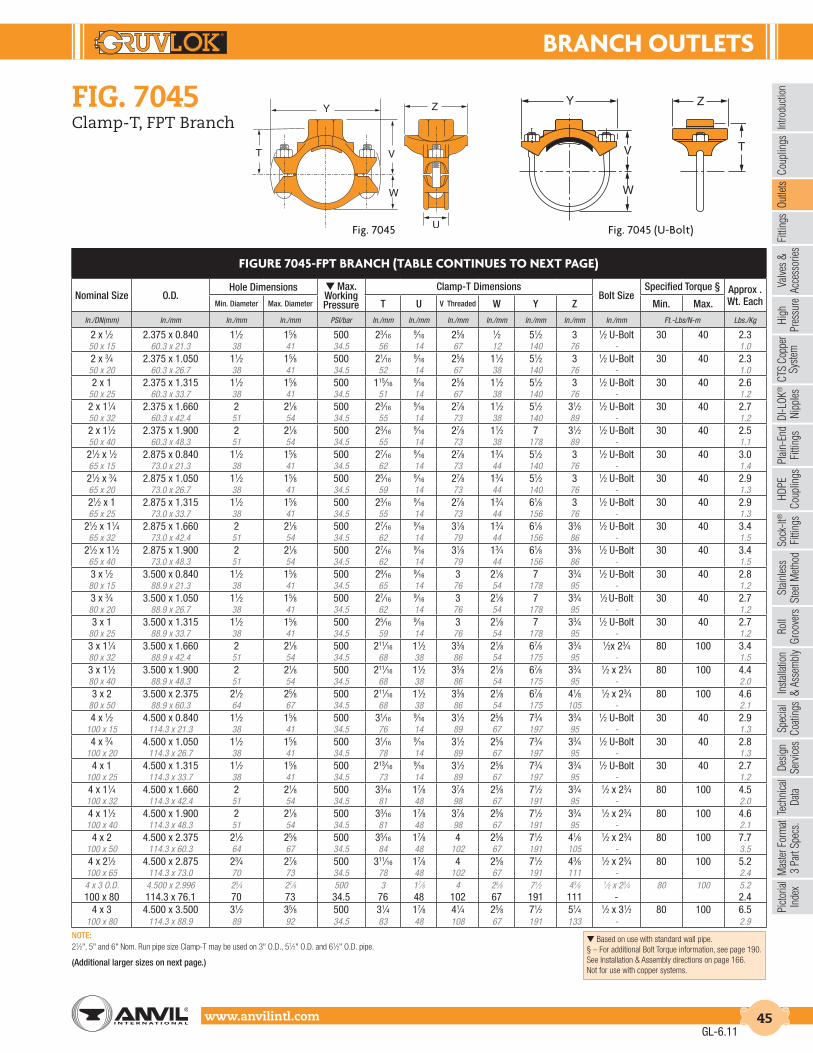
BrAncH outLEtS
Intro
duct
ion
Coup
lings
Outle
tsFi
tting
sVa
lves
&
Acce
ssor
ies
High
Pres
sure
DI-L
OK®
Nipp
les
Plai
n-En
dFi
tting
sHD
PECo
uplin
gsSo
ck-It
®
Fitti
ngs
Stai
nles
sSt
eel M
etho
dRo
ll Gr
oove
rsIn
stal
latio
n&
Ass
embl
ySp
ecia
lCo
atin
gsDe
sign
Serv
ices
Tech
nica
lDa
taM
aste
r For
mat
3 Pa
rt Sp
ecs.
Pict
oria
lIn
dex
CTS
Copp
er
Syst
em
www.anvilintl.com 45
fiG. 7045Clamp-T, FPT Branch
FIGurE 7045-FPt BrAncH (tABLE contInuES to nEXt PAGE)
Nominal Size O.D.Hole Dimensions ▼ Max.
Working Pressure
Clamp-T DimensionsBolt Size
Specified Torque § Approx . Wt. Each Min. Diameter Max. Diameter T U V Threaded W Y Z Min. Max.
In./DN(mm) In./mm In./mm In./mm PSI/bar In./mm In./mm In./mm In./mm In./mm In./mm In./mm Ft.-Lbs/N-m Lbs./Kg
2 x 1⁄2 2.375 x 0.840 11⁄2 15⁄8 500 23⁄16 9⁄16 25⁄8 1⁄2 51⁄2 3 1⁄2 U-Bolt 30 40 2.350 x 15 60.3 x 21.3 38 41 34.5 56 14 67 12 140 76 - 1.02 x 3⁄4 2.375 x 1.050 11⁄2 15⁄8 500 21⁄16 9⁄16 25⁄8 11⁄2 51⁄2 3 1⁄2 U-Bolt 30 40 2.350 x 20 60.3 x 26.7 38 41 34.5 52 14 67 38 140 76 - 1.02 x 1 2.375 x 1.315 11⁄2 15⁄8 500 115⁄16 9⁄16 25⁄8 11⁄2 51⁄2 3 1⁄2 U-Bolt 30 40 2.6
50 x 25 60.3 x 33.7 38 41 34.5 51 14 67 38 140 76 - 1.22 x 11⁄4 2.375 x 1.660 2 21⁄8 500 23⁄16 9⁄16 27⁄8 11⁄2 51⁄2 31⁄2 1⁄2 U-Bolt 30 40 2.750 x 32 60.3 x 42.4 51 54 34.5 55 14 73 38 140 89 - 1.22 x 11⁄2 2.375 x 1.900 2 21⁄8 500 23⁄16 9⁄16 27⁄8 11⁄2 7 31⁄2 1⁄2 U-Bolt 30 40 2.550 x 40 60.3 x 48.3 51 54 34.5 55 14 73 38 178 89 - 1.121⁄2 x 1⁄2 2.875 x 0.840 11⁄2 15⁄8 500 27⁄16 9⁄16 27⁄8 13⁄4 51⁄2 3 1⁄2 U-Bolt 30 40 3.065 x 15 73.0 x 21.3 38 41 34.5 62 14 73 44 140 76 - 1.421⁄2 x 3⁄4 2.875 x 1.050 11⁄2 15⁄8 500 25⁄16 9⁄16 27⁄8 13⁄4 51⁄2 3 1⁄2 U-Bolt 30 40 2.965 x 20 73.0 x 26.7 38 41 34.5 59 14 73 44 140 76 - 1.321⁄2 x 1 2.875 x 1.315 11⁄2 15⁄8 500 23⁄16 9⁄16 27⁄8 13⁄4 61⁄8 3 1⁄2 U-Bolt 30 40 2.965 x 25 73.0 x 33.7 38 41 34.5 55 14 73 44 156 76 - 1.3
21⁄2 x 11⁄4 2.875 x 1.660 2 21⁄8 500 27⁄16 9⁄16 31⁄8 13⁄4 61⁄8 33⁄8 1⁄2 U-Bolt 30 40 3.465 x 32 73.0 x 42.4 51 54 34.5 62 14 79 44 156 86 - 1.5
21⁄2 x 11⁄2 2.875 x 1.900 2 21⁄8 500 27⁄16 9⁄16 31⁄8 13⁄4 61⁄8 33⁄8 1⁄2 U-Bolt 30 40 3.465 x 40 73.0 x 48.3 51 54 34.5 62 14 79 44 156 86 - 1.53 x 1⁄2 3.500 x 0.840 11⁄2 15⁄8 500 29⁄16 9⁄16 3 21⁄8 7 33⁄4 1⁄2 U-Bolt 30 40 2.880 x 15 88.9 x 21.3 38 41 34.5 65 14 76 54 178 95 - 1.23 x 3⁄4 3.500 x 1.050 11⁄2 15⁄8 500 27⁄16 9⁄16 3 21⁄8 7 33⁄4 1⁄2 U-Bolt 30 40 2.780 x 20 88.9 x 26.7 38 41 34.5 62 14 76 54 178 95 - 1.23 x 1 3.500 x 1.315 11⁄2 15⁄8 500 25⁄16 9⁄16 3 21⁄8 7 33⁄4 1⁄2 U-Bolt 30 40 2.7
80 x 25 88.9 x 33.7 38 41 34.5 59 14 76 54 178 95 - 1.23 x 11⁄4 3.500 x 1.660 2 21⁄8 500 211⁄16 11⁄2 33⁄8 21⁄8 67⁄8 33⁄4 1⁄2x 23⁄4 80 100 3.480 x 32 88.9 x 42.4 51 54 34.5 68 38 86 54 175 95 - 1.53 x 11⁄2 3.500 x 1.900 2 21⁄8 500 211⁄16 11⁄2 33⁄8 21⁄8 67⁄8 33⁄4 1⁄2 x 23⁄4 80 100 4.480 x 40 88.9 x 48.3 51 54 34.5 68 38 86 54 175 95 - 2.03 x 2 3.500 x 2.375 21⁄2 25⁄8 500 211⁄16 11⁄2 33⁄8 21⁄8 67⁄8 41⁄8 1⁄2 x 23⁄4 80 100 4.6
80 x 50 88.9 x 60.3 64 67 34.5 68 38 86 54 175 105 - 2.14 x 1⁄2 4.500 x 0.840 11⁄2 15⁄8 500 31⁄16 9⁄16 31⁄2 25⁄8 73⁄4 33⁄4 1⁄2 U-Bolt 30 40 2.9
100 x 15 114.3 x 21.3 38 41 34.5 76 14 89 67 197 95 - 1.34 x 3⁄4 4.500 x 1.050 11⁄2 15⁄8 500 31⁄16 9⁄16 31⁄2 25⁄8 73⁄4 33⁄4 1⁄2 U-Bolt 30 40 2.8
100 x 20 114.3 x 26.7 38 41 34.5 78 14 89 67 197 95 - 1.34 x 1 4.500 x 1.315 11⁄2 15⁄8 500 213⁄16 9⁄16 31⁄2 25⁄8 73⁄4 33⁄4 1⁄2 U-Bolt 30 40 2.7
100 x 25 114.3 x 33.7 38 41 34.5 73 14 89 67 197 95 - 1.24 x 11⁄4 4.500 x 1.660 2 21⁄8 500 33⁄16 17⁄8 37⁄8 25⁄8 71⁄2 33⁄4 1⁄2 x 23⁄4 80 100 4.5100 x 32 114.3 x 42.4 51 54 34.5 81 48 98 67 191 95 - 2.04 x 11⁄2 4.500 x 1.900 2 21⁄8 500 33⁄16 17⁄8 37⁄8 25⁄8 71⁄2 33⁄4 1⁄2 x 23⁄4 80 100 4.6100 x 40 114.3 x 48.3 51 54 34.5 81 48 98 67 191 95 - 2.1
4 x 2 4.500 x 2.375 21⁄2 25⁄8 500 35⁄16 17⁄8 4 25⁄8 71⁄2 41⁄8 1⁄2 x 23⁄4 80 100 7.7100 x 50 114.3 x 60.3 64 67 34.5 84 48 102 67 191 105 - 3.54 x 21⁄2 4.500 x 2.875 23⁄4 27⁄8 500 311⁄16 17⁄8 4 25⁄8 71⁄2 43⁄8 1⁄2 x 23⁄4 80 100 5.2100 x 65 114.3 x 73.0 70 73 34.5 78 48 102 67 191 111 - 2.44 x 3 O.D. 4.500 x 2.996 23⁄4 27⁄8 500 3 17⁄8 4 25⁄8 71⁄2 43⁄8 1⁄2 x 23⁄4 80 100 5.2100 x 80 114.3 x 76.1 70 73 34.5 76 48 102 67 191 111 - 2.4
4 x 3 4.500 x 3.500 31⁄2 35⁄8 500 31⁄4 17⁄8 41⁄4 25⁄8 71⁄2 51⁄4 1⁄2 x 31⁄2 80 100 6.5100 x 80 114.3 x 88.9 89 92 34.5 83 48 108 67 191 133 - 2.9
Fig. 7045 (U-Bolt)
Z
V T
Y
W
Fig. 7045
GL-6.11
▼ Based on use with standard wall pipe.§ – For additional Bolt Torque information, see page 190.See Installation & Assembly directions on page 166.Not for use with copper systems.
NOTE:21⁄2", 5" and 6" Nom. Run pipe size Clamp-T may be used on 3" O.D., 51⁄2" O.D. and 61⁄2" O.D. pipe.
(Additional larger sizes on next page.)

BrAncH outLEtS
www.anvilintl.com46
Fig. 7045 (U-Bolt)
Z
V T
Y
W
Fig. 7045
fiG. 7045Clamp-T, FPT Branch
FIGurE 7045-FPt BrAncH (contInuEd FroM PrEVIouS PAGE)
Nominal Size O.D.Hole Dimensions ▼ Max.
Working Pressure
Clamp-T DimensionsBolt Size
Specified Torque § Approx . Wt. Each Min. Diameter Max. Diameter T U V Threaded W Y Z Min. Max.
In./DN(mm) In./mm In./mm In./mm PSI/bar In./mm In./mm In./mm In./mm In./mm In./mm In./mm Ft.-Lbs/N-m Lbs./Kg
5 x 11⁄4 5.563 x 1.660 2 21⁄8 500 311⁄16 17⁄8 43⁄8 31⁄4 91⁄8 33⁄4 5⁄8 x 31⁄4 100 130 5.4125 x 32 141.3 x 42.4 51 54 34.5 94 48 111 83 232 95 - 2.4
5 x 11⁄2 5.563 x 1.900 2 21⁄8 500 311⁄16 17⁄8 43⁄8 31⁄4 91⁄8 33⁄4 5⁄8 x 31⁄4 100 130 5.5125 x 40 141.3 x 48.3 51 54 34.5 94 48 111 83 232 95 - 2.5
5 x 2 5.563 x 2.375 21⁄2 25⁄8 500 313⁄16 17⁄8 41⁄2 31⁄4 91⁄8 41⁄8 5⁄8 x 31⁄4 100 130 5.7125 x 50 141.3 x 60.3 64 67 34.5 97 48 114 83 232 105 - 2.6
5 x 21⁄2 5.563 x 2.875 23⁄4 27⁄8 500 313⁄16 17⁄8 43⁄4 31⁄4 91⁄8 43⁄8 5⁄8 x 31⁄4 100 130 7.0125 x 65 141.3 x 73.0 70 73 34.5 97 48 121 83 232 111 - 3.2
5 x 3 O.D. 5.563 x 2.996 23⁄4 27⁄8 500 33⁄4 17⁄8 43⁄4 31⁄4 91⁄8 43⁄8 5⁄8 x 31⁄4 130 180 7.0
125 x 80 141.3 x 76.1 70 73 34.5 95 48 121 83 232 111 - 3.25 x 3 5.563 x 3.500 31⁄2 35⁄8 500 4 17⁄8 5 31⁄4 91⁄8 51⁄4 5⁄8 x 31⁄4 100 130 8.7
125 x 80 141.3 x 88.9 89 92 34.5 102 48 127 83 232 133 - 3.9
6 x 11⁄4 6.625 x 1.660 2 21⁄8 500 43⁄16 2 47⁄8 37⁄8 101⁄8 33⁄4 5⁄8 x 41⁄4 100 130 7.8150 x 32 168.3 x 42.4 51 54 34.5 106 51 124 98 257 95 - 3.5
6 x 11⁄2 6.625 x 1.900 2 21⁄8 500 43⁄16 2 47⁄8 37⁄8 101⁄8 33⁄4 5⁄8 x 41⁄4 100 130 7.8150 x 40 168.3 x 48.3 51 54 34.5 106 51 124 98 257 95 - 3.5
6 x 2 6.625 x 2.375 21⁄2 25⁄8 500 43⁄16 2 47⁄8 37⁄8 101⁄8 41⁄8 5⁄8 x 41⁄4 100 130 7.8150 x 50 168.3 x 60.3 64 67 34.5 106 51 124 98 257 105 - 3.5
6 x 21⁄2 6.625 x 2.875 23⁄4 27⁄8 500 43⁄16 2 51⁄8 37⁄8 101⁄8 43⁄8 5⁄8 x 41⁄4 100 130 8.4150 x 65 168.3 x 73.0 70 73 34.5 106 51 130 98 257 111 - 3.8
6 x 3 O.D. 6.625 x 2.996 23⁄4 27⁄8 500 41⁄8 2 51⁄8 37⁄8 101⁄8 43⁄8 5⁄8 x 41⁄4 100 130 8.4
150 x 80 168.3 x 76.1 70 73 34.5 105 51 130 98 257 111 - 3.86 x 3 6.625 x 3.500 31⁄2 35⁄8 500 43⁄8 2 53⁄8 37⁄8 101⁄8 51⁄4 5⁄8 x 41⁄4 100 130 9.6
150 x 80 168.3 x 88.9 89 92 34.5 111 51 137 98 257 133 - 4.4
6 x 4 6.625 x 4.500 41⁄2 45⁄8 500 43⁄8 2 51⁄2 37⁄8 101⁄8 61⁄2 5⁄8 x 41⁄4 100 130 10.5150 x 100 168.3 x 114.3 114 117 34.5 111 51 140 98 257 165 - 4.8
8 x 2 8.625 x 2.750 21⁄2 25⁄8 500 53⁄16 21⁄4 57⁄8 5 123⁄4 41⁄8 3⁄4 x 41⁄4 130 180 11.3200 x 50 219.1 x 70.0 64 67 34.5 132 57 149 127 324 105 - 5.1
8 x 21⁄2 8.625 x 2.875 23⁄4 27⁄8 500 55⁄16 21⁄4 61⁄4 5 123⁄4 43⁄8 3⁄4 x 41⁄2 130 180 11.1200 x 65 219.1 x 73.0 70 73 34.5 134 57 159 127 324 111 - 5.0
8 x 3 O.D. 8.625 x 2.996 23⁄4 27⁄8 500 51⁄4 21⁄4 61⁄4 5 123⁄4 43⁄8 3⁄4 x 41⁄2 130 180 11.1
200 x 80 219.1 x 76.1 70 73 34.5 133 57 159 127 324 111 - 5.08 x 3 8.625 x 3.500 31⁄2 35⁄8 500 53⁄8 21⁄4 63⁄8 5 123⁄4 51⁄4 3⁄4 x 41⁄2 130 180 13.0
200 x 80 219.1 x 88.9 89 92 34.5 137 57 162 127 324 133 - 5.9
8 x 4 8.625 x 4.500 41⁄2 45⁄8 500 53⁄8 21⁄4 61⁄2 5 123⁄4 61⁄2 3⁄4 x 41⁄2 130 180 16.2200 x 100 219.1 x 114.3 114 117 34.5 137 57 165 127 324 165 - 7.3
GL-7.12
▼ Based on use with standard wall pipe.§ – For additional Bolt Torque information, see page 190.See Installation & Assembly directions on page 166.Not for use with copper systems.
NOTE:21⁄2", 5" and 6" Nom. Run pipe size Clamp-T may be used on 3" O.D., 51⁄2" O.D. and 61⁄2" O.D. pipe.
(Additional smaller sizes on previous page.)

BrAncH outLEtS
Intro
duct
ion
Coup
lings
Outle
tsFi
tting
sVa
lves
&
Acce
ssor
ies
High
Pres
sure
DI-L
OK®
Nipp
les
Plai
n-En
dFi
tting
sHD
PECo
uplin
gsSo
ck-It
®
Fitti
ngs
Stai
nles
sSt
eel M
etho
dRo
ll Gr
oove
rsIn
stal
latio
n&
Ass
embl
ySp
ecia
lCo
atin
gsDe
sign
Serv
ices
Tech
nica
lDa
taM
aste
r For
mat
3 Pa
rt Sp
ecs.
Pict
oria
lIn
dex
CTS
Copp
er
Syst
em
www.anvilintl.com 47
fiG. 7046Clamp-T, Grooved Branch
material specifications
AnSI BoLtS & HEAVY HEX nutS:Heat treated, oval neck track head bolts conforming to ASTM A 183 Grade 2 with a minimum tensile strength of 110,000 psi and heavy hex nuts of carbon steel conforming to ASTM A 563 Grade A or Grade B, or J995 Grade 2. Bolts and nuts are provided zinc electroplated as standard.
MEtrIc BoLtS & HEAVY HEX nutS:Heat treated, zinc electroplated oval-neck track head bolts made of carbon steel with mechanical properties per ISO 898-1 Class 8.8. Hex nuts are zinc electroplated followed by a yellow chromate dip.
u-BoLt:Cold drawn steel and zinc plated.
StAInLESS StEEL BoLtS & nutS:Stainless Steel Bolts and Nuts are also available. Contact an AnvilRepresentative for more information.
HouSInG:Ductile Iron conforming to ASTM A 536, Grade 65-45-12
coAtInGS:Rust inhibiting paint – Color: ORANGE (standard)Hot Dipped Zinc Galvanized (optional)Other Colors Available (IE: RAL3000 and RAL9000)For other Coating requirements contact an Anvil Representative formore information.
GASKEtS: MaterialsProperties as designated in accordance with ASTM D 2000
Grade “E” EPDM (Green color code)-40°F to 230°F (Service Temperature Range)(-40°C to 110°C)Recommended for water service, diluted acids, alkalies solutions, oil-free air and many other chemical services.NOT FOR USE IN PETROLEUM APPLICATIONS.
Grade “EP” EPDM (Green and Red color code)-40°F to 250°F (Service Temperature Range)(-40°C to 121°C)Recommended for water service, diluted acids, alkalies solutions, oil-free air and many other chemical services.NOT FOR USE IN PETROLEUM APPLICATIONS.
For hot water applications the use of Gruvlok Extreme Temperature lubricant is recommended. NSF-61 Certified for cold and hot water applications up through 12".
Grade “T” Nitrile (Orange color code)-20°F to 180°F (Service Temperature Range)(-29°C to 82°C)Recommended for petroleum applications. air with oil vapors and vegetable and mineral oils.NOT FOR USE IN HOT WATER OR HOT AIR.
LuBrIcAtIon:Standard GruvlokGruvlok XtremeTM (Do Not use with Grade “L”)
The Gruvlok Clamp-T provides a quick and easy outlet at any location along the pipe. A hole drilled or cut in the pipe to receive the locating collar of the Clamp-T is all that is required. The full, smooth outlet area provides for optimum flow characteristics.
The Clamp-T housing is specially engineered to conform to the pipe O.D. and the Clamp-T gasket providing a leak-tight reliable seal in both positive pressure and vacuum conditions. The maximum working pressure for all sizes is 500 PSI (34.5 bar) when assembled on standard wall steel pipe.
The Gruvlok Clamp-T provides for a branch or cross connection in light wall or standard wall steel pipe.
Clamp-T cross connections are available in most sizes allowing greater versatility in piping design.
cLAMP-t FLoW dAtA (FrIctIonAL rESIStAncE)
Branch SizeFig. 7046 Grooved Branch
C.V. Value Equiv. Pipe Length
In./DN/mm Ft./Meters
11/4 5.4 5.0
32 1.5
11/2 95 3.5
40 1.1
2 148 4.5
50 1.4
21/2 205 7.0
65 2.1
3 294 9.5
80 2.9
4 571 7.0
100 2.1
GL-7.12
For Listings/Approval Details and Limitations,visit our website at www.anvilintl.com orcontact an Anvil® Sales Representative.

BrAncH outLEtS
www.anvilintl.com48
Z
V
Y
W
fiG. 7046Clamp-T, Grooved Branch
Fig. 7046Fig. 7046 (U-Bolt)
FIGurE 7046-Gr BrAncH
Nominal Size O.D.
Hole Dimensions ▼ Max. Working Pressure
Clamp-T Dimensions Bolt Size
Specified Torque § Approx. Wt. Each Min. Diameter Max. Diameter U V Grooved W Y Z Min. Max.
In./DN(mm) In./mm In./mm In./mm PSI/bar In./mm In./mm In./mm In./mm In./mm In./mm Ft.-Lbs/N-m Lbs./Kg
21⁄2 x 11⁄4• 2.875 x 1.660 2 21⁄8 500 9⁄16 31⁄8 13⁄4 61⁄8 31⁄2 1⁄2 U-Bolt 30 40 3.465 x 32 73.0 x 42.4 51 54 34.5 14 79 44 156 89 - 1.5
21⁄2 x 11⁄2 2.875 x 1.900 2 21⁄8 500 9⁄16 31⁄8 13⁄4 61⁄8 31⁄2 1⁄2 U-Bolt 30 40 3.465 x 40 73.0 x 48.3 51 54 34.5 14 79 44 156 89 - 1.53 x 11⁄4 3.500 x 1.660 2 21⁄8 500 11⁄2 31⁄2 21⁄8 67⁄8 33⁄4 1⁄2 x 23⁄4 80 100 3.480 x 32 88.9 x 42.4 51 54 34.5 38 89 54 175 95 - 1.53 x 11⁄2 3.500 x 1.900 2 21⁄8 500 11⁄2 31⁄2 21⁄8 67⁄8 33⁄4 1⁄2 x 23⁄4 80 100 4.480 x 40 88.9 x 48.3 51 54 34.5 38 89 54 175 95 - 2.03 x 2 3.500 x 2.375 21⁄2 25⁄8 500 11⁄2 31⁄2 21⁄8 67⁄8 41⁄8 1⁄2 x 23⁄4 80 100 4.6
80 x 50 88.9 x 60.3 64 67 34.5 38 89 54 175 105 - 2.14 x 11⁄4 4.500 x 1.660 2 21⁄8 500 17⁄8 4 25⁄8 71⁄2 33⁄4 1⁄2 x 23⁄4 80 100 4.2100 x 32 114.3 x 42.4 51 54 34.5 48 102 67 191 95 - 1.94 x 11⁄2 4.500 x 1.900 2 21⁄8 500 17⁄8 4 25⁄8 71⁄2 33⁄4 1⁄2 x 23⁄4 80 100 4.3100 x 40 114.3 x 48.3 51 54 34.5 48 102 67 191 95 - 2.0
4 x 2 4.500 x 2.375 21⁄2 25⁄8 500 17⁄8 4 25⁄8 71⁄2 41⁄8 1⁄2 x 23⁄4 80 100 4.6100 x 50 114.3 x 60.3 64 67 34.5 48 102 67 191 105 - 2.14 x 21⁄2 4.500 x 2.875 23⁄4 27⁄8 500 17⁄8 4 25⁄8 71⁄2 43⁄8 1⁄2 x 23⁄4 80 100 5.0100 x 65 114.3 x 73.0 70 73 34.5 48 102 67 191 111 - 2.34 x 3 O.D. 4.500 x 2.996 23⁄4 27⁄8 500 17⁄8 4 25⁄8 71⁄2 43⁄8 1⁄2 x 23⁄4 80 100 5.0100 x 80 114.3 x 76.1 70 73 34.5 48 102 67 191 111 - 2.3
4 x 3 4.500 x 3.500 31⁄2 35⁄8 500 17⁄8 4 25⁄8 71⁄2 51⁄4 1⁄2 x 31⁄2 80 100 5.6100 x 80 114.3 x 88.9 89 92 34.5 48 102 67 191 133 - 2.55 x 11⁄4 5.563 x 1.660 2 21⁄8 500 17⁄8 41⁄4 31⁄4 91⁄8 33⁄4 1⁄2 x 23⁄4 80 100 5.6125 x 32 141.3 x 42.4 51 54 34.5 48 108 83 232 95 - 2.55 x 11⁄2 5.563 x 1.900 2 21⁄8 500 17⁄8 41⁄4 31⁄4 91⁄8 33⁄4 5⁄8 x 31⁄4 100 130 5.6125 x 40 141.3 x 48.3 51 54 34.5 48 108 83 232 95 - 2.5
5 x 2 5.563 x 2.375 21⁄2 25⁄8 500 17⁄8 41⁄4 31⁄4 91⁄8 41⁄8 5⁄8 x 31⁄4 100 130 5.5125 x 50 141.3 x 60.3 64 67 34.5 48 108 83 232 105 - 2.55 x 21⁄2 5.563 x 2.875 23⁄4 27⁄8 500 17⁄8 41⁄4 31⁄4 91⁄8 43⁄8 5⁄8 x 31⁄4 100 130 5.8125 x 65 141.3 x 73.0 70 73 34.5 48 108 83 232 111 - 2.6
5 x 3 5.563 x 3.500 31⁄2 35⁄8 500 17⁄8 45⁄8 31⁄4 91⁄8 51⁄4 5⁄8 x 31⁄4 100 130 7.1125 x 80 141.3 x 88.9 89 92 34.5 48 117 83 232 133 - 3.26 x 11⁄2 6.625 x 1.900 2 21⁄8 500 2 5 37⁄8 101⁄8 33⁄4 5⁄8 x 41⁄4 100 130 7.2150 x 40 168.3 x 48.3 51 54 34.5 51 127 98 257 95 * 3.3
6 x 2 6.625 x 2.375 21⁄2 25⁄8 500 2 5 37⁄8 101⁄8 41⁄8 5⁄8 x 41⁄4 100 130 7.8150 x 50 168.3 x 60.3 64 67 34.5 51 127 98 257 105 * 3.56 x 21⁄2 6.625 x 2.875 23⁄4 27⁄8 500 2 51⁄8 37⁄8 101⁄8 43⁄8 5⁄8 x 41⁄4 100 130 7.6150 x 65 168.3 x 73.0 70 73 34.5 51 130 98 257 111 * 3.46 x 3 O.D. 6.625 x 2.996 23⁄4 27⁄8 500 2 51⁄8 37⁄8 101⁄8 43⁄8 5⁄8 x 41⁄4 100 130 7.6150 x 80 168.3 x 76.1 70 73 34.5 51 130 98 257 111 * 3.4
6 x 3 6.625 x 3.500 31⁄2 35⁄8 500 2 51⁄8 37⁄8 101⁄8 51⁄4 5⁄8 x 41⁄4 100 130 8.0150 x 80 168.3 x 88.9 89 92 34.5 51 130 98 257 133 * 3.6
6 x 4 6.625 x 4.500 41⁄2 45⁄8 500 2 51⁄4 37⁄8 101⁄8 61⁄2 5⁄8 x 41⁄4 100 130 10.4150 x 100 168.3 x 114.3 114 117 34.5 51 133 98 257 165 * 4.7
8 x 2 8.625 x 2.375 21⁄2 25⁄8 500 21⁄4 61⁄8 5 123⁄4 41⁄4 3⁄4 x 41⁄2 130 180 10.4200 x 50 219.1 x 60.3 64 67 34.5 57 156 127 324 108 - 4.78 x 21⁄2 8.625 x 2.875 23⁄4 27⁄8 500 21⁄4 61⁄8 5 123⁄4 43⁄8 3⁄4 x 41⁄2 130 180 10.6200 x 65 219.1 x 73.0 70 73 34.5 57 156 127 324 111 M20 x 110 175 245 4.8
8 x 3 8.625 x 3.500 31⁄2 35⁄8 500 21⁄4 61⁄8 5 123⁄4 51⁄4 3⁄4 x 41⁄2 130 180 11.5200 x 80 219.1 x 88.9 89 92 34.5 57 156 127 324 133 M20 x 110 175 245 5.2
8 x 4 8.625 x 4.500 41⁄2 45⁄8 500 21⁄4 61⁄4 5 123⁄4 61⁄2 3⁄4 x 41⁄2 130 180 16.2200 x 100 219.1 x 114.3 114 117 34.5 57 159 127 324 165 M20 x 110 175 245 7.3
GL-6.11
▼ Based on use with standard wall pipe.§ – For additional Bolt Torque information, see page 190.See Installation & Assembly directions on page 166.Not for use with copper systems.
NOTES:21⁄2", 5" and 6" Nom. Run pipe size Clamp-T may be used on 3" O.D., 51⁄2" O.D. and 61⁄2" O.D. pipe.• Cannot be used in cross configuration.

BrAncH outLEtS
Intro
duct
ion
Coup
lings
Outle
tsFi
tting
sVa
lves
&
Acce
ssor
ies
High
Pres
sure
DI-L
OK®
Nipp
les
Plai
n-En
dFi
tting
sHD
PECo
uplin
gsSo
ck-It
®
Fitti
ngs
Stai
nles
sSt
eel M
etho
dRo
ll Gr
oove
rsIn
stal
latio
n&
Ass
embl
ySp
ecia
lCo
atin
gsDe
sign
Serv
ices
Tech
nica
lDa
taM
aste
r For
mat
3 Pa
rt Sp
ecs.
Pict
oria
lIn
dex
CTS
Copp
er
Syst
em
www.anvilintl.com 49
fiG. 7047, fiG. 7048 & fiG. 7049Clamp-T, Cross
material specifications
AnSI BoLtS & HEAVY HEX nutS:Heat treated, oval neck track head bolts conforming to ASTM A 183 Grade 2 with a minimum tensile strength of 110,000 psi and heavy hex nuts of carbon steel conforming to ASTM A 563 Grade A or Grade B, or J995 Grade 2. Bolts and nuts are provided zinc electroplated as standard.
MEtrIc BoLtS & HEAVY HEX nutS:Heat treated, zinc electroplated oval-neck track head bolts made of carbon steel with mechanical properties per ISO 898-1 Class 8.8. Hex nuts are zinc electroplated followed by a yellow chromate dip.
StAInLESS StEEL BoLtS & nutS:Stainless steel bolts and nuts are also available. Contact an AnvilRepresentative for more information.
HouSInG:Ductile Iron conforming to ASTM A 536, Grade 65-45-12 or Malleable Iron conforming to ASTM A 47, Grade 32510.
coAtInGS:Rust inhibiting paint – Color: ORANGE (standard)Hot Dipped Zinc Galvanized (optional)Other Colors Available (IE: RAL3000 and RAL9000)For other Coating requirements contact an Anvil Representative for more information.
GASKEtS: MaterialsProperties as designated in accordance with ASTM D 2000
Grade “E” EPDM (Green color code)-40°F to 230°F (Service Temperature Range)(-40°C to 110°C)Recommended for water service, diluted acids, alkalies solutions, oil-free air and many other chemical services.NOT FOR USE IN PETROLEUM APPLICATIONS.
Grade “EP” EPDM (Green and Red color code)-40°F to 250°F (Service Temperature Range)(-40°C to 121°C)Recommended for water service, diluted acids, alkalies solutions, oil-free air and many other chemical services.NOT FOR USE IN PETROLEUM APPLICATIONS.
For hot water applications the use of Gruvlok Extreme Temperature lubricant is recommended. NSF-61 Certified for cold and hot water applications up through 12".
Grade “T” Nitrile (Orange color code)-20°F to 180°F (Service Temperature Range)(-29°C to 82°C)Recommended for petroleum applications. air with oil vapors and vegetable and mineral oils.NOT FOR USE IN HOT WATER OR HOT AIR.
LuBrIcAtIon:Standard GruvlokGruvlok XtremeTM (Do Not use with Grade “L”)
Not for use in copper systems.
The Gruvlok Clamp-T provides a branch or cross connection in light wall or standard wall steel pipe.
The Fig. 7045 Clamp-T female pipe thread branch is available with NPT or ISO 7/1 connection and the Fig. 7046 Clamp-T has grooved-end branch connection.
Clamp-T cross connections are available allowing greater versatility in piping design.
NOTE: 2 1⁄2" x 1 1/4" Figure 7046 cannot be used in cross configuration.Fig. 7047 Fig. 7048 Fig. 7049
Fig. 7047 - Thread x Thread Fig. 7048 - Groove x Groove Fig. 7049 - Groove x Thread
Z Y
V
V T
Y Z
V
V
Y Z
V
V
GL-7.12
For Listings/Approval Details and Limitations,visit our website at www.anvilintl.com orcontact an Anvil® Sales Representative.

BrAncH outLEtS
www.anvilintl.com50
fiG. 7044Branch Outlet
The Gruvlok Fig. 7044 Branch Outlet is for direct connection of sprinkler heads and drop nipples. Just cut a hole, saddle up and fasten it with the U-bolt. The branch outlet provides an economical, quick, and easy outlet at any location along a pipe. Specially engineered to conform to the pipe O.D., the Fig. 7044 provides a leak tight reliable seal in both positive pressure and vacuum conditions. Ductile iron housings with Grade E gasket and carbon steel U-bolt (3⁄8" dia.) with flanged nuts. Ductile iron housings is available black.
The maximum working pressure for all sizes is 175 PSI (12.1 bar).
material specifications
GASKEtS: MaterialsProperties as designated in accordance with ASTM D 2000
Grade “E” EPDM (Green color code)-40°F to 150°F (Service Temperature Range)(-40°C to 66°C) Recommended for waterservice, diluted acids, alkalies solutions, oil-freeair and many chemical services.NOT FOR USE IN PETROLEUM APPLICATIONS.
HouSInG:Ductile Iron conforming to ASTM A 536,Grade 65-45-12.
u-BoLt:Plated U-bolt conforming to ASTM A 307 with plated hex nuts conforming to ASTM A 563.
LuBrIcAtIon:Standard GruvlokGruvlok XtremeTM
Not for use in copper systems.§ – For additional Bolt Torque information, see page 190.See Installation & Assembly directions on page 167.
FIGurE 7044 BrAncH outLEt
Nominal Size O.D.
Hole Diameter Dimensions Specified Torque § Approx. Wt. EachMin. Dia. Max. Dia. A B C Take-out T Min. Max.
In./DN(mm) In./mm In./mm In./mm In./mm In./mm In./mm In./mm Ft.-Lbs./N-m Lbs./Kg
11⁄4 x 1⁄2 1.660 x 0.840 13⁄16 11⁄4 21⁄16 31⁄2 27⁄32 13⁄8 27 33 0.8
32 x 15 42.4 x 21.3 30 32 53 89 56 35 - - 0.4
11⁄4 x 3⁄4 1.660 x 1.050 13⁄16 11⁄4 21⁄16 31⁄2 27⁄32 13⁄8 27 33 0.8
32 x 20 42.4 x 26.7 30 32 53 89 56 35 - - 0.4
11⁄4 x 1 1.660 x 1.315 13⁄16 11⁄4 23⁄16 31⁄2 27⁄32 11⁄2 27 33 0.9
32 x 25 42.4 x 33.7 30 32 56 89 56 38 - - 0.4
11⁄2 x 1⁄2 1.900 x 0.840 13⁄16 11⁄4 25⁄32 31⁄2 27⁄32 13⁄8 27 33 0.8
40 x 15 48.3 x 21.3 30 32 55 89 56 35 - - 0.4
11⁄2 x 3⁄4 1.900 x 1.050 13⁄16 11⁄4 25⁄32 31⁄2 27⁄32 13⁄8 27 33 0.8
40 x 20 48.3 x 26.7 30 32 55 89 56 35 - - 0.4
11⁄2 x 1 1.900 x 1.315 13⁄16 11⁄4 29⁄32 31⁄2 27⁄32 11⁄2 27 33 0.9
40 x 25 48.3 x 33.7 30 32 58 89 56 38 - - 0.4
2 x 1⁄2 2.375 x 0.840 13⁄16 11⁄4 21⁄2 37⁄8 27⁄32 15⁄8 27 33 0.8
50 x 15 60.3 x 21.3 30 32 64 98 56 42 - - 0.4
2 x 3⁄4 2.375 x 1.050 13⁄16 11⁄4 21⁄2 37⁄8 27⁄32 15⁄8 27 33 0.8
50 x 20 60.3 x 26.7 30 32 64 98 56 42 - - 0.4
2 x 1 2.375 x 1.315 13⁄16 11⁄4 25⁄8 37⁄8 27⁄32 13⁄4 27 33 0.9
50 x 25 60.3 x 33.7 30 32 67 98 56 45 - - 0.4
21⁄2 x 1⁄2 2.875 x 0.840 13⁄16 11⁄4 211⁄16 43⁄8 27⁄32 2 27 33 0.8
65 x 15 73.0 x 21.3 30 32 69 111 56 51 - - 0.4
21⁄2 x 3⁄4 2.875 x 1.050 13⁄16 11⁄4 211⁄16 43⁄8 27⁄32 2 27 33 0.9
65 x 20 73.0 x 26.7 30 32 69 111 56 51 - - 0.4
21⁄2 x 1 2.875 x 1.315 13⁄16 11⁄4 213⁄16 43⁄8 27⁄32 21⁄8 27 33 1.0
65 x 25 73.0 x 33.7 30 32 72 111 56 54 - - 0.5
For Listings/Approval Details and Limitations,visit our website at www.anvilintl.com orcontact an Anvil® Sales Representative.
GL-7.12

GruVLoK FIttInGS
Intro
duct
ion
Coup
lings
Outle
tsFi
tting
sVa
lves
&
Acce
ssor
ies
High
Pres
sure
DI-L
OK®
Nipp
les
Plai
n-En
dFi
tting
sHD
PECo
uplin
gsSo
ck-It
®
Fitti
ngs
Stai
nles
sSt
eel M
etho
dRo
ll Gr
oove
rsIn
stal
latio
n&
Ass
embl
ySp
ecia
lCo
atin
gsDe
sign
Serv
ices
Tech
nica
lDa
taM
aste
r For
mat
3 Pa
rt Sp
ecs.
Pict
oria
lIn
dex
CTS
Copp
er
Syst
em
www.anvilintl.com 51
Gruvlok fittinGs for Grooved-end pipe
material specifications
cASt FIttInGS:Ductile iron conforming to ASTM A 536, Grade 65-45-12Malleable iron conforming to ASTM A 47
FABrIcAtEd FIttInGS:1-6" Carbon steel, Schedule 40, conforming to ASTM A 53, Grade B8-12" Carbon steel, Schedule 30, conforming to ASTM A 53, Grade B14-24" Carbon steel, 0.375 wall, conforming to ASTM A 53, Grade B
coAtInGS:Rust inhibiting paint – Color: ORANGE (standard)Hot Dipped Zinc Galvanized conforming to ASTM A 153 (optional)Other Colors Available (IE: RAL3000 and RAL9000)
The Fitting Size Chart is used to determine theO.D. of the pipe that the fittings is to be used with.Gruvlok Fittings are identified by either the Nominalsize in inches or the Pipe O.D. in/mm.
Nominal Size O.D.
In./DN(mm) In./mm
1 1.31525 33.411⁄4 1.66032 42.411⁄2 1.90040 48.32 2.37550 60.321⁄2 2.87565 73.0
3 O.D. 2.99676.1 76.1
3 3.50080 88.931⁄2 4.00065 101.6
41⁄4 O.D. 4.250108.0 108.0
4 4.500100 114.3
51⁄4 O.D. 5.236133.0 133.0
51⁄2 O.D. 5.500139.7 139.7
Nominal Size O.D.
In./DN(mm) In./mm
5 5.563140 141.3
61⁄4 O.D. 6.259159.0 159.0
61⁄2 O.D. 6.500165.1 165.1
6 6.625150 168.38 8.625
200 219.110 10.750250 273.012 12.750300 323.914 14.000350 355.616 16.000400 406.418 18.000450 457.220 20.000500 508.024 24.000600 609.6
FIttInG SIZE
For the reducing tee and branches, use the value that is corresponding to the branch size. For example: for 6" x 6" x 3" tee, the branch value of 3" is 12.8 ft (3.9).
FLoW dAtA – FrIctIonAL rESIStAncE (EXPrESSEd AS EQuIVALEnt StrAIGHt PIPE)
Nom. Size O.D. Pipe Wall
ThicknessElbow Tee
90° 45° Branch Run
In./DN(mm) In./mm In./mm Ft./m Ft./m Ft./m Ft./m
1 1.315 0.133 1.7 0.9 4.4 1.725 33.4 3.4 0.5 0.3 1.3 0.511⁄4 1.660 0.140 2.3 1.2 5.8 2.332 42.2 3.6 0.7 0.4 1.8 0.711⁄2 1.900 0.145 2.7 1.3 6.7 2.740 48.3 3.7 0.8 0.4 2.0 0.82 2.375 0.154 3.4 1.7 8.6 3.450 60.3 3.9 1.0 0.5 2.6 1.021⁄2 2.875 0.203 4.1 2.1 10.3 4.165 73.0 5.2 1.2 0.6 3.1 1.2
3 O.D. 2.996 0.197 4.3 2.2 10.8 4.376.1 76.1 5.0 1.3 0.7 3.3 1.3
3 3.500 0.216 5.1 2.6 12.8 5.180 88.9 5.5 1.6 0.8 3.9 1.6
41⁄4 O.D. 4.250 0.220 6.4 3.2 16.1 6.4108.0 108.0 5.6 2.0 1.0 4.9 2.0
4 4.500 0.237 6.7 3.4 16.8 6.7100 114.3 6.0 2.0 1.0 5.1 2.0
51⁄4 O.D. 5.236 0.248 8.0 4.0 20.1 8.0133.0 133.0 6.3 2.4 1.2 6.1 2.4
51⁄2 O.D. 5.500 0.248 8.3 4.2 20.9 8.3139.7 139.7 6.3 2.5 1.3 6.4 2.5
5 5.563 0.258 8.4 4.2 21.0 8.4125 141.3 6.6 2.6 1.3 6.4 2.6
61⁄4 O.D. 6.259 0.280 9.7 4.9 24.3 9.7159.0 159.0 7.1 3.0 1.5 7.4 3.0
61⁄2 O.D. 6.500 0.280 10.0 5.0 24.9 10.0165.1 165.1 7.1 3.0 1.5 7.6 3.0
6 6.625 0.280 10.1 5.1 25.3 10.1150 168.3 7.1 3.1 1.6 7.7 3.18 8.625 0.322 13.3 6.7 33.3 13.3
200 219.1 8.2 4.1 2.0 10.1 4.110 10.750 0.365 16.7 8.4 41.8 16.7250 273.1 9.3 5.1 2.6 12.7 5.112 12.750 0.375 20.0 10.0 50.0 20.0300 323.9 9.5 6.1 3.0 15.2 6.114 14.000 0.375 22.2 17.7 64.2 22.9350 355.6 9.5 6.8 5.4 19.6 7.016 16.000 0.375 25.5 20.4 73.9 26.4400 406.4 9.5 7.8 6.2 22.5 8.018 18.000 0.375 28.9 23.1 87.2 31.1450 457.2 9.5 8.8 7.0 26.6 9.520 20.000 0.375 32.2 25.7 97.3 34.8500 508.0 9.5 9.8 7.8 29.7 10.624 24.000 0.375 38.9 31.1 113.0 40.4600 609.6 9.5 11.9 9.5 34.4 12.3
Gruvlok fittings are available through 24" nominal pipe size in a variety of styles. Use the Fitting Size Table to convert nominal pipe size to corresponding pipe O.D.
These fittings are designed to provide minimum pressure drop and uniform strength.
Depending on styles and size, Gruvlok fittings are provided in various materials including malleable iron, ductile iron, forged steel or fabricated steel.
Pressure ratings of Gruvlok standard fittings conform to those of Fig. 7001 Gruvlok coupling.
Not for use in copper systems.For Listings/Approval Details and Limitations,
visit our website at www.anvilintl.com orcontact an Anvil® Sales Representative.
GL-7.12

GruVLoK FIttInGS
www.anvilintl.com52
C to E O.D.
fiG. 705090° Elbow*
fiG. 705145° Elbow*
fiG. 705222 1⁄2° Elbow
fiG. 7052i22 1⁄2° Elbow
C - Cast malleable or ductile iron, all others are fabricated steel.* 14”-24” Standard Radius 90° & 45° Elbows are 1 1⁄2.Center to end dimensions and weights may differ from those shown in chart, contact an Anvil Representative for more information.
FIGurE 7050 90° ELBoW*
Nominal Size O.D. Center
to EndApprox. Wt. Ea.
In./DN(mm) In./mm In./mm Lbs./Kg
1 1.315 21⁄4 C 0.625 33.4 57 0.311⁄4 1.660 23⁄4 C 1.032 42.2 70 0.511⁄2 1.900 23⁄4 C 1.240 48.3 70 0.52 2.375 31⁄4 C 1.750 60.3 83 0.821⁄2 2.875 33⁄4 C 2.665 73.0 95 1.2
3 O.D. 2.996 4 C 3.676.1 76.1 102 1.6
3 3.500 41⁄4 C 4.080 88.9 108 1.831⁄2 4.000 41⁄2 C 5.590 101.6 114 2.5
41⁄4 O.D. 4.250 43⁄4 C 7.7108.0 108.0 121 3.5
4 4.500 5 C 7.7100 114.3 127 3.5
51⁄4 O.D. 5.236 51⁄4 C 10.4133.0 133.0 133 4.7
51⁄2 O.D. 5.500 51⁄4 C 10.9139.7 139.7 133 4.9
5 5.563 51⁄2 C 11.1125 141.3 140 5.0
61⁄4 O.D. 6.259 6 C 15.2159.0 159.0 152 6.9
61⁄2 O.D. 6.500 61⁄2 C 17.4165.1 165.1 165 7.9
6 6.625 61⁄2 C 16.5150 168.3 165 7.58 8.625 73⁄4 C 30.6
200 219.1 197 13.910 10.750 9 C 53.5250 273.1 229 24.312 12.750 10 C 82300 323.9 254 37.214 14.000 21 169.0350 355.6 533 76.716 16.000 24 222.0400 406.4 610 100.718 18.000 27 280.0450 457.2 686 127.020 20.000 30 344.0500 508.0 762 156.024 24.000 36 490.0600 609.6 914 222.3
FIGurE 7051 45° ELBoW*
Nominal Size O.D. Center
to EndApprox. Wt. Ea.
In./DN(mm) In./mm In./mm Lbs./Kg
1 1.315 13⁄4 C 0.525 33.4 44 0.211⁄4 1.660 13⁄4 C 0.732 42.2 44 0.311⁄2 1.900 13⁄4 C 0.940 48.3 44 0.42 2.375 2 C 1.550 60.3 51 0.721⁄2 2.875 21⁄4 C 1.965 73.0 57 0.9
3 O.D. 2.996 21⁄2 C 2.276.1 76.1 64 1.0
3 3.500 21⁄2 C 3.380 88.9 64 1.531⁄2 4.000 23⁄4 C 4.390 101.6 70 2.0
41⁄4 O.D. 4.250 27⁄8 C 4.4108.0 108.0 83 2.0
4 4.500 3 C 5.4100 114.3 76 2.4
51⁄4 O.D. 5.236 31⁄4 C 7.3133.0 133.0 83 3.3
51⁄2 O.D. 5.500 31⁄4 C 7.8139.7 139.7 83 3.5
5 5.563 31⁄4 C 9.0125 141.3 83 4.1
61⁄4 O.D. 6.259 31⁄2 C 10.1159.0 159.0 89 4.6
61⁄2 O.D. 6.500 31⁄2 C 11.1165.1 165.1 89 5.0
6 6.625 31⁄2 C 11.2150 168.3 89 5.18 8.625 41⁄4 C 19.8
200 219.1 108 9.010 10.750 43⁄4 C 34.3250 273.1 121 15.612 12.750 51⁄4 C 50.0300 323.9 133 22.714 14.000 83⁄4 92.0350 355.6 222 41.716 16.000 10 117.0400 406.4 254 53.118 18.000 111⁄4 146.0450 457.2 286 66.220 20.000 121⁄2 179.0500 508.0 317 81.224 24.000 15 255.0600 609.6 381 115.7
FIGurE 7052 221⁄2° ELBoW*
Nominal Size O.D. Center
to EndApprox. Wt. Ea.
In./DN(mm) In./mm In./mm Lbs./Kg
1 1.315 31⁄4 0.525 33.4 83 0.211⁄4 1.660 13⁄4 0.732 42.2 44 0.311⁄2 1.900 13⁄4 0.840 48.3 44 0.42 2.375 17⁄8 C 1.550 60.3 48 0.721⁄2 2.875 2 1.965 73.0 51 0.93 3.500 21⁄4 C 3.280 88.9 57 1.531⁄2 4.000 21⁄2 4.090 101.6 64 1.84 4.500 25⁄8 C 5.3
100 114.3 67 2.45 5.563 27⁄8 7.2
125 141.3 73 3.36 6.625 31⁄8 C 8.2
150 168.3 79 3.78 8.625 37⁄8 C 17.8
200 219.1 98 8.110 10.750 43⁄8 30.0250 273.1 111 13.612 12.750 47⁄8 40.4300 323.9 124 18.314 14.000 5 46.0350 355.6 127 20.916 16.000 5 52.2400 406.4 127 23.718 18.000 51⁄2 65.0450 457.2 140 29.520 20.000 6 80.0500 508.0 152 36.324 24.000 7 112.0600 609.6 178 50.8
FIGurE 7052i 221⁄2° ELBoW*
Nominal Size O.D. Center
to EndApprox. Wt. Ea.
In./DN(mm) In./mm In./mm Lbs./Kg
1 1.315 15⁄8 0.525 33.4 41.28 0.22711⁄4 1.675 13⁄4 1.032 42.2 44.45 0.45411⁄2 1.900 13⁄4 1.040 48.3 44.45 0.4542 2.375 17⁄8 1.550 60.3 47.63 0.68021⁄2 2.875 2 2.065 73.0 50.8 0.907
3 O.D. 2.996 2 2.076.1 76.1 50.8 0.907
3 3.500 21⁄4 2.580 88.9 57.15 1.1344 4.5 25⁄8 5.0
100 114.3 66.68 2.26851/2 O.D. 5.500 27⁄8 7.0139.7 139.7 73.03 3.175
5 5.563 27⁄8 7.5125 141.3 73.03 3.402
61/2 O.D. 6.500 31⁄8 10.0165.1 165.1 79.38 4.536
6 6.625 31/8 10.0150 168.3 79.38 4.5368 8.625 37/8 18.5
200 219.1 98.43 8.39110 10.75 43/8 32.5250 237.1 111.13 14.74112 12.75 47/8 48.0300 323.9 123.83 21.772
Cast Fabricated
C to E
O.D. C to E O.D. C to E
O.D.
For Listings/Approval Details and Limitations,visit our website at www.anvilintl.com orcontact an Anvil® Sales Representative.
C to EO.D.
All 7052i fittings are cast ductile iron.
GL-6.11

GruVLoK FIttInGS
Intro
duct
ion
Coup
lings
Outle
tsFi
tting
sVa
lves
&
Acce
ssor
ies
High
Pres
sure
DI-L
OK®
Nipp
les
Plai
n-En
dFi
tting
sHD
PECo
uplin
gsSo
ck-It
®
Fitti
ngs
Stai
nles
sSt
eel M
etho
dRo
ll Gr
oove
rsIn
stal
latio
n&
Ass
embl
ySp
ecia
lCo
atin
gsDe
sign
Serv
ices
Tech
nica
lDa
taM
aste
r For
mat
3 Pa
rt Sp
ecs.
Pict
oria
lIn
dex
CTS
Copp
er
Syst
em
www.anvilintl.com 53
fiG. 7050lr90° Long Radius Elbow*
fiG. 7051lr45° Long Radius Elbow*
C - Cast malleable or ductile iron, all others are fabricated steel.* 14"-24" Standard Radius 90° & 45° Elbows are 1 1⁄ 2.Center to end dimensions and weights may differ from those shown in chart, Contact an Anvil Representative for more information.
FIGurE 7050 Lr LonG rAdIuS 90° ELBoW*
Nominal Size O.D. Center
to EndApprox. Wt. Ea.
In./DN(mm) In./mm In./mm Lbs./Kg
1 1.315 31⁄2 0.925 33.4 89 0.4
11⁄4 1.660 37⁄8 1.332 42.2 98 0.6
11⁄2 1.900 41⁄4 1.740 48.3 108 0.8
2 2.375 43⁄8 2.550 60.3 136 1.1
21⁄2 2.875 53⁄4 4.965 73.0 146 2.2
3 3.500 57⁄8 6.580 88.9 181 2.9
31⁄2 4.000 71⁄4 9.790 101.6 184 4.4
4 4.500 71⁄2 11.5100 114.3 191 5.2
5 5.563 91⁄2 20.9125 141.3 241 9.5
6 6.625 103⁄4 29.1150 168.3 273 13.2
8 8.625 15 59.2200 219.1 381 26.9
10 10.750 18 104.0250 273.1 457 47.2
12 12.750 21 147.0300 323.9 533 66.7
14 14.000 21 169.0350 355.6 533 76.7
16 16.000 24 222.0400 406.4 610 100.7
18 18.000 27 280.0450 457.2 686 127.0
20 20.000 30 344.0500 508.0 762 156.0
24 24.000 36 490.0600 609.6 914 222.3
FIGurE 7051 Lr LonG rAdIuS 45° ELBoW*
Nominal Size O.D. Center
to EndApprox. Wt. Ea.
In./DN(mm) In./mm In./mm Lbs./Kg
1 1.315 21⁄2 0.725 33.4 64 0.3
11⁄4 1.660 21⁄2 1.032 42.2 64 0.5
11⁄2 1.900 21⁄2 1.240 48.3 64 0.5
2 2.375 23⁄4 1.750 60.3 70 0.8
21⁄2 2.875 3 2.965 73.0 76 1.3
3 3.500 33⁄8 4.380 88.9 86 2.0
31⁄2 4.000 31⁄2 5.390 101.6 89 2.4
4 4.500 4 7.2100 114.3 102 3.3
5 5.563 5 12.2125 141.3 127 5.5
6 6.625 51⁄2 17.4150 168.3 140 7.9
8 8.625 71⁄4 34.0200 219.1 184 15.4
10 10.750 81⁄2 57.4250 273.1 216 26.0
12 12.750 10 82.6300 323.9 254 37.5
14 14.000 83⁄4 92.0350 355.6 222 41.7
16 16.000 10 117.0400 406.4 254 53.1
18 18.000 111⁄4 146.0450 457.2 286 66.2
20 20.000 121⁄2 179.0500 508.0 317 81.2
24 24.000 15 255.0600 609.6 381 115.7
C to E
O.D.
C to E O.D.
For Listings/Approval Details and Limitations,visit our website at www.anvilintl.com orcontact an Anvil® Sales Representative.
fiG. 705311 1⁄4° Elbow
FIGurE 7053 111⁄4° ELBoW*
NominalSize O.D. Center
to EndApprox.Wt. Ea.
In./DN(mm) In./mm In./mm Lbs./Kg
1 1.315 13⁄8 0.325 33.4 35 0.1
11⁄4 1.660 13⁄8 0.532 42.2 35 0.2
11⁄2 1.900 13⁄8 0.740 48.3 35 0.3
2 2.375 13⁄8 0.950 60.3 35 0.4
21⁄2 2.875 11⁄2 1.565 73.0 38 0.7
3 3.500 11⁄2 2.080 88.9 38 0.9
31⁄2 4.000 13⁄4 2.890 101.6 44 1.3
4 4.500 13⁄4 3.3100 114.3 44 1.5
5 5.563 2 5.0125 141.3 51 2.3
6 6.625 2 6.5150 168.3 51 2.9
8 8.625 2 10.0200 219.1 51 4.5
10 10.750 21⁄8 14.5250 273.1 54 6.6
12 12.750 21⁄4 18.7300 323.9 57 8.5
14 14.000 31⁄2 32.1350 355.6 89 14.6
16 16.000 4 42.0400 406.4 102 19.1
18 18.000 41⁄2 53.2450 457.2 114 24.1
20 20.000 5 65.7500 508.0 127 29.8
24 24.000 6 96.0600 609.6 152 43.5
C to E O.D.
GL-7.12

GruVLoK FIttInGS
www.anvilintl.com54
CastFabricated
C to E
C to E
O.D.
C to E
O.D.
C to E
fiG. 7063Tee w/ Threaded Branch
fiG. 7061Reducing Tee Standard
C - Cast malleable or ductile iron, all others are fabricated steel.
Center to end dimensions and weights may differ from those shown in chart, contact an Anvil Representative for more information.See Fitting Size chart on page 51 for O.D.
FIGurE 7063 tEE WItH tHrEAdEd BrAncH
Nominal Size O.D. C to
GEC to TE
Approx. Wt. Ea.
In./DN(mm) In./mm In./mm In./mm Lbs./Kg
1 1.315 21⁄4 21⁄4 0.925 33.4 57 57 0.4
11⁄4 1.660 23⁄4 23⁄4 1.432 42.2 70 70 0.6
11⁄2 1.900 23⁄4 23⁄4 1.740 48.3 70 70 0.8
2 2.375 31⁄4 41⁄4 2.950 60.3 83 108 1.3
21⁄2 2.875 33⁄4 33⁄4 4.765 73.0 95 95 2.1
3 3.500 41⁄4 6 8.180 88.9 108 152 3.7
31⁄2 4.000 41⁄2 41⁄2 8.890 101.6 114 114 4.0
4 4.500 5 71⁄4 13.5100 114.3 127 184 6.1
5 5.563 51⁄2 51⁄2 16.7125 140 140 140 7.6
6 6.625 61⁄2 61⁄2 25.6150 168.3 165 165 11.6
8 8.625 73⁄4 73⁄4 45.0200 219.1 197 197 20.4
10 10.750 9 9 73.0250 273.1 229 229 33.1
12 12.750 10 10 98.0300 323.9 254 254 44.5
Nominal Size Center to End
Approx. Wt. Ea.
In./DN(mm) In./mm Lbs./Kg
11⁄4 x 11⁄4 x 1 23⁄4 1.532 x 32 x 25 70 0.7
11⁄2 x 11⁄2 x 1 23⁄4 1.840 x 40 x 25 70 0.8
11⁄2 x 11⁄2 x 11⁄4 23⁄4 1.840 x 40 x 32 70 0.82 x 2 x 1 31⁄4 C 2.6
50 x 50 x 25 83 1.22 x 2 x 11⁄4 31⁄4 1.750 x 50 x 32 83 0.82 x 2 x 11⁄2 31⁄4 C 2.750 x 50 x 40 83 1.2
21⁄2 x 21⁄2 x 1 33⁄4 4.165 x 65 x 25 95 1.9
21⁄2 x 21⁄2 x 11⁄4 33⁄4 4.265 x 65 x 32 95 1.9
21⁄2 x 21⁄2 x 11⁄2 33⁄4 4.365 x 65 x 40 95 2.0
21⁄2 x 21⁄2 x 2 33⁄4 4.465 x 65 x 50 95 2.03 x 3 x 1 41⁄4 C 7.0
80 x 80 x 25 108 3.23 x 3 x 11⁄4 41⁄4 5.880 x 80 x 32 108 2.63 x 3 x 11⁄2 41⁄4 5.980 x 80 x 40 108 2.73 x 3 x 2 41⁄4 C 5.5
80 x 80 x 50 108 2.53 x 3 x 21⁄2 41⁄4 6.380 x 80 x 65 108 2.94 x 4 x 1 33⁄4 7.0
100 x 100 x 25 95 3.24 x 4 x 11⁄4 5 9.6
100 x 100 x 32 127 4.44 x 4 x 11⁄2 5 10.2
100 x 100 x 40 127 4.64 x 4 x 2 5 C 10.2
100 x 100 x 50 127 4.64 x 4 x 21⁄2 5 C 11.2
100 x 100 x 65 127 5.14 x 4 x 3 5 C 11.4
100 x 100 x 80 127 5.25 x 5 x 1 51⁄2 13.6
125 x 125 x 25 140 6.25 x 5 x 11⁄2 51⁄2 13.8
125 x 125 x 40 140 6.35 x 5 x 2 51⁄2 14
125 x 125 x 50 140 6.45 x 5 x 21⁄2 51⁄2 14.3
125 x 125 x 65 140 6.55 x 5 x 3 51⁄2 14.6
125 x 125 x 80 140 6.65 x 5 x 4 51⁄2 C 17.9
125 x 125 x 100 140 8.16 x 6 x 1 61⁄2 20.5
150 x 150 x 25 165 9.36 x 6 x 11⁄2 61⁄2 21.0
150 x 150 x 40 165 9.56 x 6 x 2 61⁄2 C 26.4
150 x 150 x 50 165 12.0
Nominal Size Center to End
Approx. Wt. Ea.
In./DN(mm) In./mm Lbs./Kg
6 x 6 x 21⁄2 61⁄2 C 26.5150 x 150 x 65 165 12.0
6 x 6 x 3 61⁄2 C 26.5150 x 150 x 80 165 12.0
6 x 6 x 4 61⁄2 C 26.5150 x 150 x 100 165 12.0
6 x 6 x 5 61⁄2 C 28.0150 x 150 x 125 165 12.7
8 x 8 x 11⁄2 73⁄4 33.0200 x 200 x 40 197 15.0
8 x 8 x 2 73⁄4 32.7200 x 200 x 50 197 14.8
8 x 8 x 21⁄2 73⁄4 33.0200 x 200 x 65 197 15.0
8 x 8 x 3 73⁄4 33.5200 x 200 x 80 197 15.2
8 x 8 x 4 73⁄4 C 50.0200 x 200 x 100 197 22.7
8 x 8 x 5 73⁄4 34.7200 x 200 x 125 197 15.7
8 x 8 x 6 73⁄4C 54.0200 x 200 x 150 197 24.510 x 10 x 11⁄2 9 52.0250 x 250 x 40 229 23.610 x 10 x 2 9 52.2
250 x 250 x 50 229 23.710 x 10 x 21⁄2 9 52.6250 x 250 x 65 229 23.910 x 10 x 3 9 53.0
250 x 250 x 80 229 24.010 x 10 x 4 9 53.6
250 x 250 x 100 229 24.310 x 10 x 5 9 54.2
250 x 250 x 125 229 24.610 x 10 x 6 9 55.0
250 x 250 x 150 229 24.910 x 10 x 8 9 64.7
250 x 250 x 200 229 29.312 x 12 x 1 10 77.0
300 x 300 x 25 254 34.912 x 12 x 2 10 80.0
300 x 300 x 50 254 36.312 x 12 x 21⁄2 10 78.0300 x 300 x 65 254 35.412 x 12 x 3 10 74.6
300 x 300 x 80 254 33.812 x 12 x 4 10 75.1
300 x 300 x 100 254 34.112 x 12 x 5 10 75.6
300 x 300 x 125 254 34.312 x 12 x 6 10 76.2
300 x 300 x 150 254 34.612 x 12 x 8 10 76.3
300 x 300 x 200 254 34.612 x 12 x 10 10 77.6
300 x 300 x 250 254 35.214 x 14 x 4 11 100.0
350 x 350 x 100 279 45.414 x 14 x 6 11 101
350 x 350 x 150 279 45.8
Nominal Size Center to End
Approx. Wt. Ea.
In./DN(mm) In./mm Lbs./Kg
14 x 14 x 8 11 103350 x 350 x 200 279 46.714 x 14 x 10 11 104
350 x 350 x 250 279 47.214 x 14 x 12 11 105
350 x 350 x 300 279 47.616 x 16 x 4 12 126
400 x 400 x 100 305 57.216 x 16 x 6 12 127
400 x 400 x 150 305 57.616 x 16 x 8 12 128
400 x 400 x 200 305 58.116 x 16 x 10 12 129
400 x 400 x 250 305 58.516 x 16 x 12 12 130
400 x 400 x 300 305 59.016 x 16 x 14 12 132
400 x 400 x 350 305 59.918 x 18 x 4 151⁄2 188
450 x 450 x 100 394 85.318 x 18 x 6 151⁄2 190
450 x 450 x 150 394 86.218 x 18 x 8 151⁄2 192
450 x 450 x 200 394 87.118 x 18 x 10 151⁄2 194
450 x 450 x 250 394 88.018 x 18 x 12 151⁄2 196
450 x 450 x 300 394 88.918 x 18 x 14 151⁄2 201
450 x 450 x 350 394 91.218 x 18 x 16 151⁄2 203
450 x 450 x 400 394 92.120 x 20 x 6 171⁄4 240
500 x 500 x 150 438 108.920 x 20 x 8 171⁄4 242
500 x 500 x 200 438 109.820 x 20 x 10 171⁄4 244
500 x 500 x 250 438 110.720 x 20 x 12 171⁄4 246
500 x 500 x 300 438 111.620 x 20 x 14 171⁄4 248
500 x 500 x 350 438 112.520 x 20 x 16 171⁄4 250
500 x 500 x 400 438 113.420 x 20 x 18 171⁄4 252
500 x 500 x 450 438 114.324 x 24 x 8 20 327
600 x 600 x 200 508 148.324 x 24 x 10 20 330
600 x 600 x 250 508 149.724 x 24 x 12 20 334
600 x 600 x 300 508 151.524 x 24 x 14 20 340
600 x 600 x 350 508 154.224 x 24 x 16 20 342
600 x 600 x 400 508 155.124 x 24 x 18 20 345
600 x 600 x 450 508 156.524 x 24 x 20 20 347
600 x 600 x 500 508 157.4
FIGurE 7061 StAndArd rEducInG tEE
C to TE
C to GE
O.D.
For Listings/Approval Details and Limitations,visit our website at www.anvilintl.com orcontact an Anvil® Sales Representative.
GL-6.11

GruVLoK FIttInGS
Intro
duct
ion
Coup
lings
Outle
tsFi
tting
sVa
lves
&
Acce
ssor
ies
High
Pres
sure
DI-L
OK®
Nipp
les
Plai
n-En
dFi
tting
sHD
PECo
uplin
gsSo
ck-It
®
Fitti
ngs
Stai
nles
sSt
eel M
etho
dRo
ll Gr
oove
rsIn
stal
latio
n&
Ass
embl
ySp
ecia
lCo
atin
gsDe
sign
Serv
ices
Tech
nica
lDa
taM
aste
r For
mat
3 Pa
rt Sp
ecs.
Pict
oria
lIn
dex
CTS
Copp
er
Syst
em
www.anvilintl.com 55
C to E
C to E
O.D.
C to E
C to E
O.D.
fiG. 7064Reducing Tee w/ Threaded Branch
fiG. 7060Tee
Cast Fabricated Cast Fabricated
C - Cast malleable or ductile iron, all others are fabricated steel.See Fitting Size chart on page 51 for O.D.
Nominal Size
Center to End
Approx. Wt. Ea.
In./DN(mm) In./mm Lbs/Kg
2 x 2 x 3⁄4 31⁄4 1.650 x 50 x 20 83 0.72 x 2 x 1 31⁄4 C 2.6
50 x 50 x 25 83 1.22 x 2 x 11⁄4 31⁄4 1.750 x 50 x 32 83 0.82 x 2 x 11⁄2 31⁄4 C 2.750 x 50 x 40 83 1.2
21⁄2 x 21⁄2 x 1 33⁄4 4.165 x 65 x 25 95 1.9
21⁄2 x 21⁄2 x 11⁄2 33⁄4 4.365 x 65 x 40 95 2
21⁄2 x 21⁄2 x 2 33⁄4 4.465 x 65 x 50 95 23 x 3 x 3⁄4 41⁄4 5.7
80 x 80 x 20 108 2.63 x 3 x 1 41⁄4 C 7.0
80 x 80 x 25 108 3.23 x 3 x 11⁄2 41⁄4 5.380 x 80 x 40 108 2.43 x 3 x 2 41⁄4 5.5
80 x 80 x 50 108 2.53 x 3 x 21⁄2 41⁄4 5.880 x 80 x 65 108 2.64 x 4 x 3⁄4 33⁄4 7.2
100 x 100 x 20 95 3.34 x 4 x 1 33⁄4 7.0
100 x 100 x 25 95 3.24 x 4 x 11⁄2 5 9.2
100 x 100 x 40 127 4.24 x 4 x 2 5 10.2
100 x 100 x 50 127 4.64 x 4 x 21⁄2 5 11.2
100 x 100 x 65 127 5.14 x 4 x 3 5 11.4
100 x 100 x 80 127 5.25 x 5 x 2 51⁄2 14.5
125 x 125 x 50 140 6.65 x 5 x 3 51⁄2 16.1
125 x 125 x 80 140 7.35 x 5 x 4 51⁄2 17.9
125 x 125 x 100 140 8.16 x 6 x 2 61⁄2 26.4
150 x 150 x 50 165 126 x 6 x 21⁄2 61⁄2 26.5
150 x 150 x 65 165 126 x 6 x 3 61⁄2 26.5
150 x 150 x 80 165 126 x 6 x 4 61⁄2 26.5
150 x 150 x 100 165 126 x 6 x 5 61⁄2 28.0
150 x 150 x 125 165 12.78 x 8 x 2 73⁄4 37.5
200 x 200 x 50 197 178 x 8 x 3 73⁄4 38.7
200 x 200 x 80 197 17.6
Nominal Size
Center to End
Approx. Wt. Ea.
In./DN(mm) In./mm Lbs/Kg
8 x 8 x 4 73⁄4 50.0200 x 200 x 100 197 22.7
8 x 8 x 5 73⁄4 41.0200 x 200 x 125 197 18.6
8 x 8 x 6 73⁄4 54.0200 x 200 x 150 197 24.5
10 x 10 x 2 9 61.8250 x 250 x 50 229 28.010 x 10 x 3 9 63.0
250 x 250 x 80 229 28.610 x 10 x 4 9 64.0
250 x 250 x 100 229 29.010 x 10 x 5 9 65.1
250 x 250 x 125 229 29.510 x 10 x 6 9 55.0
250 x 250 x 150 229 24.910 x 10 x 8 9 64.7
250 x 250 x 200 229 29.312 x 12 x 3 10 84.9
300 x 300 x 80 254 38.512 x 12 x 4 10 85.8
300 x 300 x 100 254 38.912 x 12 x 5 10 87.0
300 x 300 x 125 254 39.512 x 12 x 6 10 88.3
300 x 300 x 150 254 40.112 x 12 x 8 10 91.2
300 x 300 x 200 254 41.412 x 12 x 10 10 94.8
300 x 300 x 250 254 43.014 x 14 x 8 11 110.0
350 x 350 x 200 279 49.714 x 14 x 10 11 114.0
350 x 350 x 250 279 51.514 x 14 x 12 11 117.0
350 x 350 x 300 279 52.816 x 16 x 8 12 135.0
400 x 400 x 200 305 61.216 x 16 x 10 12 139.0
400 x 400 x 250 305 63.016 x 16 x 12 12 142.0
400 x 400 x 300 305 64.418 x 18 x 10 151⁄2 204.0
450 x 450 x 250 394 92.518 x 18 x 12 151⁄2 209.0
450 x 450 x 300 394 94.818 x 18 x 14 151⁄2 211.0
450 x 450 x 350 0 95.718 x 18 x 16 151⁄2 216.0
450 x 450 x 400 0 98.024 x 24 x 8 20 334.0
600 x 600 x 200 508 15224 x 24 x 10 20 342.0
600 x 600 x 250 508 15524 x 24 x 12 20 349.0
600 x 600 x 300 508 158
FIGurE 7064 rEducInG tEE WItH tHrEAdEd BrAncH FIGurE 7060 – tEE
Nominal Size O.D. Center
to EndApprox. Wt. Ea.
In./DN(mm) In./mm In./mm Lbs./Kg
1 1.315 21⁄4 C 0.925 33.4 57 0.411⁄4 1.660 23⁄4 C 1.532 42.2 70 0.711⁄2 1.900 23⁄4 C 1.840 48.3 70 0.82 2.375 31⁄4 C 2.450 60.3 83 1.121⁄2 2.875 33⁄4 C 4.065 73.0 95 1.8
3 O.D. 2.996 4 C 4.676.1 76.1 101 2.1
3 3.500 41⁄4 C 5.880 88.9 108 2.631⁄2 4.000 41⁄2 C 9.890 101.6 114 4.4
41⁄4 O.D. 4.250 43⁄4 C 9.3108.0 108.0 121 4.2
4 4.500 5 C 10.3100 114.3 127 4.7
51⁄4 O.D. 5.236 51⁄4 C 14.1133.0 133.0 133 6.4
51⁄2 O.D. 5.500 51⁄2 C 16.1139.7 139.7 140 7.3
5 5.563 51⁄2 C 16.2125 141.3 140 7.3
61⁄4 O.D. 6.259 6 C 20.8159.0 159.0 152 9.4
61⁄2 O.D. 6.500 61⁄2 C 24.4165.1 165.1 165 11.1
6 6.625 61⁄2 C 25.7150 168.3 165 11.78 8.625 73⁄4 C 41.1
200 219.1 197 18.610 10.750 9 C 74.5250 273.1 229 33.812 12.750 10 C 94.7300 323.9 254 43.014 14.000 11 118.0350 355.6 279 53.516 16.000 12 146.0400 406.4 305 66.218 18.000 151⁄2 218.0450 457.2 394 98.920 20.000 171⁄4 275.0500 508.0 438 12524 24.000 20 379.0600 609.6 508 172
C to E
C to E
O.D. O.D.
C to E
C to E
For Listings/Approval Details and Limitations,visit our website at www.anvilintl.com orcontact an Anvil® Sales Representative.
GL-6.11

GruVLoK FIttInGS
www.anvilintl.com56
All are Fabricated Steel.See Fitting Size chart on page 51 for O.D.
fiG. 7076Gr x Thd
Concentric Reducers
fiG. 7073 & fiG. 7097Eccentric Reducers
Fig. 7073– Gr. x Gr. Fig. 7097 – Gr. x Thd.
FabricatedFabricated
Fabricated Steel *Figure 7097 is available in sizes 11⁄4 x 1 through 12 x 10.Center to end dimensions may differ from those shown above. Contact an Anvil Representative for more information.See Fitting Size chart on page 51 for O.D.
See Fitting Size chart on page 51 for O.D.
FIGurE 7076 – concEntrIc rEducEr
GrooVE BY tHrEAd
Nominal Size End to End
Approx. Wt. Ea.
In./DN(mm) In./mm Lbs./Kg
11⁄2 x 1 21⁄2 0.640 x 25 6 4 0.32 x 3⁄4 21⁄2 1.050 x 80 64 0.52 x 1 21⁄2 0.8
50 x 25 64 0.42 x 11⁄4 21⁄2 1.350 x 32 64 0.62 x 11⁄2 21⁄2 1.350 x 40 64 0.621⁄2 x 1 21⁄2 1.065 x 25 64 0.5
21⁄2 x 11⁄4 21⁄2 1.065 x 32 64 0.5
21⁄2 x 11⁄2 21⁄2 1.365 x 40 64 0.621⁄2 x 2 21⁄2 1.265 x 50 64 0.53 x 3⁄4 21⁄2 1.280 x 80 64 0.53 x 1 21⁄2 1.2
80 x 25 64 0.53 x 11⁄2 21⁄2 1.380 x 40 64 0.63 x 2 21⁄2 1.3
80 x 50 64 0.63 x 21⁄2 21⁄2 1.580 x 65 64 0.731⁄2 x 3 3 1.890 x 80 76 0.84 x 1 3 2.2
100 x 25 76 1.04 x 11⁄2 3 2.3100 x 40 76 1.0
4 x 2 3 2.3100 x 50 76 1.04 x 21⁄2 3 2.3100 x 65 76 1.0
4 x 3 3 2.6100 x 80 76 1.24 x 31⁄2 3 2.5100 x 90 76 1.1
5 x 4 31⁄2 4.5125 x 100 89 2.0
6 x 1 4 6.0150 x 25 102 2.7
6 x 2 4 6.0150 x 50 102 2.7
6 x 3 4 6.0150 x 80 102 2.7
6 x 4 4 5.9150 x 100 102 2.7
6 x 5 4 5.8150 x 125 102 2.6
Nominal Size
End to End
Approx. Wt. Ea.
In./DN(mm) In./mm Lbs./Kg
11⁄4 x 1 81⁄2 1.532 x 25 216 0.711⁄2 x 3⁄4 81⁄2 1.640 x 20 216 0.711⁄2 x 1 81⁄2 1.740 x 25 216 0.8
11⁄2 x 11⁄4 81⁄2 4.540 x 32 216 2.02 x 3⁄4 9 2.150 x 80 229 1.02 x 1 9 2.2
50 x 25 229 1.02 x 11⁄4 9 2.450 x 32 229 1.12 x 11⁄2 9 2.550 x 40 229 1.121⁄2 x 1 91⁄2 3.265 x 25 241 1.5
21⁄2 x 11⁄4 91⁄2 3.465 x 32 241 1.5
21⁄2 x 11⁄2 91⁄2 3.665 x 40 241 1.621⁄2 x 2 91⁄2 4.065 x 50 241 1.83 x 1 91⁄2 4.0
80 x 25 241 1.83 x 11⁄4 91⁄2 4.380 x 32 241 2.03 x 11⁄2 91⁄2 4.580 x 40 241 2.03 x 2 91⁄2 4.8
80 x 50 241 2.23 x 21⁄2 91⁄2 5.680 x 65 241 2.531⁄2 x 3 91⁄2 6.690 x 80 241 3.04 x 1 10 5.9
100 x 25 254 2.74 x 11⁄4 10 6.3100 x 32 254 2.94 x 11⁄2 10 6.4100 x 40 254 2.9
4 x 2 10 6.7100 x 50 254 3.04 x 21⁄2 10 7.3100 x 65 254 3.3
4 x 3 10 7.9100 x 80 254 3.6
Nominal Size
End to End
Approx. Wt. Ea.
In./DN(mm) In./mm Lbs./Kg
4 x 31⁄2 10 8.5100 x 90 254 3.9
5 x 2 11 9.3125 x 50 279 4.25 x 21⁄2 11 9.9125 x 65 279 4.5
5 x 3 11 10.7125 x 80 279 4.9
5 x 4 11 11.9125 x 100 279 5.4
6 x 1 111⁄2 12.0150 x 25 292 5.46 x 11⁄2 111⁄2 12.1150 x 40 292 5.5
6 x 2 111⁄2 12.2150 x 50 292 5.56 x 21⁄2 111⁄2 12.8150 x 65 292 5.8
6 x 3 111⁄2 13.6150 x 80 292 6.2
6 x 4 111⁄2 14.9150 x 100 292 6.8
6 x 5 111⁄2 16.2150 x 125 292 7.3
8 x 3 12 17.9200 x 80 305 8.1
8 x 4 12 19.7200 x 100 305 8.9
8 x 5 12 21.4200 x 125 305 9.7
8 x 6 12 23.2200 x 150 305 10.5
10 x 4 13 29.7250 x 100 330 13.5
10 x 5 13 31.7250 x 125 330 14.4
10 x 6 13 34.0250 x 150 330 15.4
10 x 8 13 34.4250 x 200 330 15.6
12 x 4 14 44.8300 x 100 356 20.3
12 x 6 14 45.2300 x 150 356 20.5
12 x 8 14 47.7300 x 200 356 21.612 x 10 14 52.0
300 x 250 356 23.6
Nominal Size
End to End
Approx. Wt. Ea.
In./DN(mm) In./mm Lbs./Kg
14 x 6 13 78350 x 150 330 35.4
14 x 8 13 80350 x 200 330 36.314 x 10 13 84
350 x 250 330 38.114 x 12 13 88
350 x 300 330 39.916 x 8 14 91
400 x 200 356 41.316 x 10 14 96
400 x 250 356 43.516 x 12 14 99
400 x 300 356 44.916 x 14 14 104
400 x 350 356 47.218 x 10 15 110
450 x 250 381 49.918 x 12 15 113
450 x 300 381 51.318 x 14 15 117
450 x 350 381 53.118 x 16 15 121
450 x 400 381 54.920 x 10 20 145
500 x 250 508 65.820 x 12 20 149
500 x 300 508 67.620 x 14 20 152
500 x 350 508 68.920 x 16 20 156
500 x 400 508 70.820 x 18 20 160
500 x 450 508 72.624 x 10 20 174
600 x 250 508 78.924 x 12 20 179
600 x 300 508 81.224 x 14 20 184
600 x 350 508 83.524 x 16 20 189
600 x 400 508 85.724 x 18 20 194
600 x 450 508 8824 x 20 20 199
600 x 500 508 90.3
FIGurE 7073 & 7097 EccEntrIc rEducEr
E to E
O.D.
E to E
O.D.
E to E
O.D.
For Listings/Approval Details and Limitations,visit our website at www.anvilintl.com orcontact an Anvil® Sales Representative.
GL-6.11

GruVLoK FIttInGS
Intro
duct
ion
Coup
lings
Outle
tsFi
tting
sVa
lves
&
Acce
ssor
ies
High
Pres
sure
DI-L
OK®
Nipp
les
Plai
n-En
dFi
tting
sHD
PECo
uplin
gsSo
ck-It
®
Fitti
ngs
Stai
nles
sSt
eel M
etho
dRo
ll Gr
oove
rsIn
stal
latio
n&
Ass
embl
ySp
ecia
lCo
atin
gsDe
sign
Serv
ices
Tech
nica
lDa
taM
aste
r For
mat
3 Pa
rt Sp
ecs.
Pict
oria
lIn
dex
CTS
Copp
er
Syst
em
www.anvilintl.com 57
fiG. 7077, fiG. 7078 & fiG. 7079Swaged Nipples
Fig. 7077Gr x Gr
Fig. 7078Gr x Thd
Fig. 7079Gr x Bev
This product is not ULC Listed.See Fitting Size chart on page 51 for O.D.
Nominal Size
End to End
Approx. Wt. Ea.
In./DN(mm) In./mm Lbs./Kg
2 x 1 61⁄2 C 2.050 x 25 165 0.92 x 11⁄4 61⁄2 2.050 x 32 165 0.92 x 11⁄2 61⁄2 2.050 x 40 165 0.921⁄2 x 1 7 3.565 x 25 178 1.6
21⁄2 x 11⁄4 7 3.565 x 32 178 1.6
21⁄2 x 11⁄2 7 3.565 x 40 178 1.621⁄2 x 2 7 3.565 x 50 178 1.63 x 1 8 5.0
80 x 25 203 2.33 x 11⁄4 8 5.080 x 32 203 2.33 x 11⁄2 8 5.080 x 40 203 2.33 x 2 8 5.0
80 x 50 203 2.33 x 21⁄2 8 5.080 x 65 203 2.331⁄2 x 3 8 7.090 x 80 203 3.24 x 1 9 8.0
100 x 25 229 3.64 x 11⁄4 9 8.0100 x 32 229 3.64 x 11⁄2 9 8.0100 x 40 229 3.6
4 x 2 9 8.0100 x 50 229 3.6
Nominal Size
End to End
Approx. Wt. Ea.
In./DN(mm) In./mm Lbs./Kg
4 x 21⁄2 9 8.0100 x 65 229 3.6
4 x 3 9 8.0100 x 80 229 3.64 x 31⁄2 9 8.0100 x 90 229 3.6
5 x 2 11 12.0125 x 50 279 5.45 x 21⁄2 11 12.0125 x 65 279 5.4
5 x 3 11 12.0125 x 80 279 5.4
5 x 4 11 12.0125 x 100 279 5.4
6 x 1 12 19.0150 x 25 305 8.66 x 11⁄4 12 19.0150 x 32 305 8.66 x 11⁄2 12 19.0150 x 40 305 8.6
6 x 2 12 19.0150 x 50 305 8.66 x 21⁄2 12 19.0150 x 65 305 8.6
6 x 3 12 19.0150 x 80 305 8.66 x 31⁄2 12 17.0150 x 90 305 7.7
6 x 4 12 19.0150 x 100 305 8.6
6 x 5 12 19.0150 x 125 305 8.6
FIGurE 7077, 7078 & 7079 SWAGEd nIPPLES
E to E
O.D.
E to E
O.D.
E to E
O.D.
For Listings/Approval Details and Limitations,visit our website at www.anvilintl.com orcontact an Anvil® Sales Representative.
GL-6.11

GruVLoK FIttInGS
www.anvilintl.com58
E to E
O.D.-1 O.D.-2
E to E
O.D.-1 O.D.-2
Sizes 11/4" x 1" to 80mm x 76.1mm Sizes 4" x 1" and larger
fiG. 7072i – Gr x Gr Concentric Reducer
FIGurE 7072i concEntrIc rEducEr
For Listings/Approval Details and Limitations,visit our website at www.anvilintl.com orcontact an Anvil® Sales Representative.
Nominal Size O.D. End
to EndApprox. Wt. Ea.
In./DN(mm) In./mm In./mm Lbs/Kg
11⁄4 x 1 1.660 x 1.315 21⁄2 0.532 x 25 42.2 x 33.4 63.5 0.227
11⁄2 x 1 1.900 x 1.315 21⁄2 0.540 x 25 48.3 x 33.4 63.5 0.227
11⁄2 x 11⁄4 1.900 x 1.660 21⁄2 1.040 x 32 48.3 x 42.2 63.5 .454
2 x 1 2.375 x 1.315 21⁄2 1.050 x 25 60.3 x 33.4 63.5 .454
2 x 11⁄4 2.375 x 1.660 21⁄2 1.050 x 32 60.3 x 42.2 63.5 .454
2 x 11⁄2 2.375 x 1.900 21⁄2 1.050 x 40 60.3 x 48.3 63.5 .454
21⁄2 x 1 2.875 x 1.315 21⁄2 1.565 x 25 73.0 x 33.4 63.5 0.680
21⁄2 x 11⁄4 2.875 x 1.660 21⁄2 1.565 x 32 73.0 x 42.2 63.5 0.680
21⁄2 x 11⁄2 2.875 x 1.900 21⁄2 1.565 x 40 73.0 x 48.3 63.5 0.680
21⁄2 x 2 2.875 x 2.375 21⁄2 1.565 x 50 73.0 x 60.3 63.5 0.680
3 O.D. x 1 2.996 x 1.315 21⁄2 1.576.1 x 25 76.1 x 33.4 63.5 0.6803 O.D. x 11/4 2.996 x 1.660 21⁄2 1.576.1 x 32 76.1 x 42.2 63.5 0.6803 O.D. x 11/2 2.996 x 1.900 21⁄2 1.576.1 x 40 76.1 x 48.3 63.5 0.6803 O.D. x 2 2.996 x 2.375 21⁄2 1.576.1 x 50 76.1 x 60.3 63.5 0.6803 x 11⁄2 3.500 x 1.900 21⁄2 1.580 x 40 88.9 x 48.3 63.5 0.680
3 x 2 3.500 x 2.375 21⁄2 2.080 x 50 88.9 x 60.3 63.5 0.907
3 x 21⁄2 3.500 x 2.875 21⁄2 2.080 x 65 88.9 x 73.0 63.5 0.907
3 x 3 O.D. 3.500 x 2.996 21⁄2 2.080 x 76.1 88.9 x 76.1 63.5 0.907
4 x 1 4.500 x 1.315 3 2.5100 x 25 114.3 x 33.4 76.2 1.134
4 x 11⁄2 4.500 x 1.900 3 2.5100 x 40 114.3 x 48.3 76.2 1.134
4 x 2 4.500 x 2.375 3 2.5100 x 50 114.3 x 60.3 76.2 1.134
4 x 21⁄2 4.500 x 2.875 3 2.5100 x 65 114.3 x 73.0 76.2 1.1344 x 3 O.D. 4.500 x 2.996 3 2.5
100 x 76.1 114.3 x 76.1 76.2 1.1344 x 3 4.500 x 3.500 3 2.5
100 x 80 114.3 x 88.9 76.2 1.13451/2 O.D. x 3 O.D. 5.500 x 2.996 31⁄2 4.0139.7 x 76.1 139.7 x 76.1 88.9 1.814
E to E
O.D.
E to E
O.D.
Cast Fabricated
fiG. 7072 – Gr x Gr Concentric Reducer
C - Cast malleable or ductile iron, all others are fabricated steel.
Nominal Size
End to End
Approx. Wt. Ea.
In./DN(mm) In./mm Lbs/Kg
11⁄4 x 1 21⁄2 0.632 x 25 64 0.311⁄2 x 1 21⁄2 0.640 x 25 64 0.3
11⁄2 x 11⁄4 21⁄2 0.640 x 32 64 0.32 x 1 21⁄2 0.8
50 x 25 64 0.42 x 11⁄4 21⁄2 C 1.350 x 32 64 0.62 x 11⁄2 21⁄2 C 1.350 x 40 64 0.621⁄2 x 1 21⁄2 1.065 x 25 64 0.5
21⁄2 x 11⁄4 21⁄2 1.065 x 32 64 0.5
21⁄2 x 11⁄2 21⁄2 1.365 x 40 64 0.621⁄2 x 2 21⁄2 C 1.665 x 50 64 0.73 x 1 21⁄2 1.2
80 x 25 64 0.53 x 11⁄4 21⁄2 1.380 x 32 64 0.63 x 11⁄2 21⁄2 1.380 x 40 64 0.63 x 2 21⁄2 C 1.4
80 x 50 64 0.63 x 21⁄2 21⁄2 C 1.580 x 65 64 0.731⁄2 x 3 3 1.890 x 80 76 0.84 x 1 3 2.2
100 x 25 76 1.04 x 11⁄4 3 2.2100 x 32 76 1.04 x 11⁄2 3 2.3100 x 40 76 1.0
4 x 2 3 C 2.4100 x 50 76 1.14 x 21⁄2 3 C 2.6100 x 65 76 1.2
4 x 3 3 C 3.2100 x 80 76 1.54 x 31⁄2 3 3.6100 x 90 76 1.6
5 x 2 31⁄2 4.6125 x 50 89 2.15 x 21⁄2 31⁄2 4.5125 x 65 89 2.0
5 x 3 31⁄2 4.4125 x 80 89 2.0
5 x 4 31⁄2 C 4.5125 x 100 89 2.0
6 x 1 4 6.8150 x 25 102 3.16 x 11⁄2 4 6.9150 x 40 102 3.1
6 x 2 4 C 6.0150 x 50 102 2.76 x 21⁄2 4 6.0150 x 65 102 2.7
6 x 3 4 C 5.4150 x 80 102 2.4
6 x 4 4 C 5.6150 x 100 102 2.5
6 x 5 4 C 6.0150 x 125 102 2.7
8 x 3 5 12.0200 x 80 127 5.5
Nominal Size
End to End
Approx. Wt. Ea.
In./DN(mm) In./mm Lbs/Kg
8 x 4 5 C 9.0200 x 100 127 4.1
8 x 5 5 11.5200 x 125 127 5.2
8 x 6 5 C 10.6200 x 150 127 4.8
10 x 4 6 20250 x 100 152 9.1
10 x 5 6 20250 x 125 152 9.1
10 x 6 6 C 20250 x 150 152 9.1
10 x 8 6 23.9250 x 200 152 10.8
12 x 4 7 25300 x 100 178 11.3
12 x 6 7 29300 x 150 178 13.2
12 x 8 7 29300 x 200 178 13.212 x 10 7 32.4
300 x 250 178 14.714 x 6 13 54.3
350 x 150 330 24.614 x 8 13 54.5
350 x 200 330 24.714 x 10 13 55.7
350 x 250 330 25.314 x 12 13 57.3
350 x 300 330 26.016 x 8 14 65.4
400 x 200 356 29.716 x 10 14 66.7
400 x 250 356 30.316 x 12 14 68.1
400 x 300 356 30.916 x 14 14 71.0
400 x 350 356 32.218 x 10 15 82.3
450 x 250 381 37.318 x 12 15 83.6
450 x 300 381 37.918 x 14 15 86.2
450 x 350 381 39.118 x 16 15 87.2
450 x 400 381 39.620 x 10 20 123.0
500 x 250 508 55.820 x 12 20 125.0
500 x 300 508 56.720 x 14 20 129.0
500 x 350 508 58.520 x 16 20 131.0
500 x 400 508 59.420 x 18 20 133.0
500 x 450 508 60.324 x 10 20 147.0
600 x 250 508 66.724 x 12 20 149.0
600 x 300 508 67.624 x 14 20 152.0
600 x 350 508 68.924 x 16 20 153.0
600 x 400 508 69.424 x 18 20 154.0
600 x 450 508 69.924 x 20 20 155.0
600 x 500 508 70.3
FIGurE 7072 concEntrIc rEducEr
Nominal Size O.D. End
to EndApprox. Wt. Ea.
In./DN(mm) In./mm In./mm Lbs/Kg
51/2 O.D. x 3 5.500 x 3.500 31⁄2 4.0139.7 x 80 139.7 x 88.9 88.9 1.81451/2 O.D. x 4 5.500 x 4.500 31⁄2 4.0
139.7 x 100 139.7 x 114.3 88.9 1.8145 x 2 5.563 x 2.375 31⁄2 4.0
125 x 50 141.3 x 60.3 88.9 1.814
5 x 21⁄2 5.563 x 2.875 31⁄2 4.0125 x 65 141.3 x 73.0 88.9 1.814
5 x 3 5.563 x 3.500 31⁄2 4.0125 x 80 141.3 x 88.9 88.9 1.814
5 x 4 5.563 x 4.5 31⁄2 5.0125 x 100 141.3 x 114.3 88.9 2.041
61/2 O.D. x 3 O.D. 6.500 x 2.996 4 5.0165.1 x 76.1 165.1 x 76.1 101.6 2.268
61/2 O.D. x 3 6.500 x 3.500 4 5.5165.1 x 80 165.1 x 88.9 101.6 2.49561/2 O.D. x 4 6.500 x 4.500 4 6.0
165.1 x 100 165.1 x 114.3 101.6 2.72061/2 O.D. x 51/2 O.D. 6.500 x 5.500 4 6.5165.1 x 139.7 165.1 x 139.7 101.6 2.948
6 x 2 6.625 x 2.375 4 5.0150 x 50 168.3 x 60.3 101.6 2.268
6 x 21⁄2 6.625 x 2.875 4 5.5150 x 65 168.3 x 73.0 101.6 2.4956 x 3 O.D. 6.625 x 2.996 4 5.5
150 x 76.1 168.3 x 76.1 101.6 2.4956 x 3 6.625 x 3.500 4 5.5
150 x 80 168.3 x 88.9 101.6 2.495
6 x 4 6.625 x 4.500 4 6.5150 x 100 168.3 x 114.3 101.6 2.948
6 x 51/2 O.D. 6.625 x 5.500 4 6.5150 x 139.7 168.3 x 139.7 101.6 2.948
6 x 5 6.625 x 5.563 4 6.0150 x 125 168.3 x 141.3 101.6 2.720
6 x 61/2 O.D. 6.625 x 6.500 4 7.5150 x 165.1 168.3 x 165.1 101.6 3.402
8 x 4 8.625 x 4.500 5 10.0200 x 100 219.1 x 114.3 127.0 4.536
8 x 61/2 O.D. 8.625 x 6.500 5 11.0200 x 165.1 219.1 x 165.1 127.0 4.990
8 x 6 8.625 x 6.625 5 11.0200 x 150 219.1 x 168.3 127.0 4.990
10 x 8 10.750 x 8.675 6 19.5250 x 200 273.1 x 219.1 152.4 8.845
All 7072i fittings are cast ductile iron.
GL-7.12

GruVLoK FIttInGS
Intro
duct
ion
Coup
lings
Outle
tsFi
tting
sVa
lves
&
Acce
ssor
ies
High
Pres
sure
DI-L
OK®
Nipp
les
Plai
n-En
dFi
tting
sHD
PECo
uplin
gsSo
ck-It
®
Fitti
ngs
Stai
nles
sSt
eel M
etho
dRo
ll Gr
oove
rsIn
stal
latio
n&
Ass
embl
ySp
ecia
lCo
atin
gsDe
sign
Serv
ices
Tech
nica
lDa
taM
aste
r For
mat
3 Pa
rt Sp
ecs.
Pict
oria
lIn
dex
CTS
Copp
er
Syst
em
www.anvilintl.com 59
fiG. 706945° Lateral
fiG. 707045° Reducing Lateral
See Fitting Size chart on page 51 for O.D.
FIGurE 7069 LAtErAL
Nominal Size O.D. Center to
Long EndCenter to Short End
Approx. Wt. Ea.
In./DN(mm) In./mm In./mm In./mm Lbs./Kg
1 1.315 5 21⁄4 1.525 33.4 127 57 0.711⁄4 1.660 53⁄4 21⁄2 2.532 42.2 146 64 1.111⁄2 1.900 61⁄4 23⁄4 3.540 48.3 159 70 1.62 2.375 7 23⁄4 4.550 60.3 178 70 2.021⁄2 2.875 73⁄4 3 10.065 73.0 197 76 4.53 3.500 81⁄2 31⁄4 11.080 88.9 216 83 5.031⁄2 4.000 10 31⁄2 14.090 101.6 254 89 6.44 4.500 101⁄2 33⁄4 18.3
100 114.3 267 95 8.35 5.563 121⁄2 4 30.0
125 141.3 318 102 13.66 6.625 14 41⁄2 46.6
150 168.3 356 114 21.18 8.625 18 6 82.8
200 219.1 457 152 37.610 10.750 201⁄2 61⁄2 127250 273.1 521 165 57.412 12.750 23 7 165300 323.9 584 178 74.814 14.000 261⁄2 71⁄2 215350 355.6 673 191 97.516 16.000 29 8 345400 406.4 737 203 15718 18.000 32 81⁄2 425450 457.2 813 216 19320 20.000 35 9 517500 508.0 889 229 23524 24.000 40 10 940600 609.6 1016 254 426
Nominal Size
Center to Long End
Center to Short End
Approx. Wt. Ea.
In./DN(mm) In./mm In./mm Lbs./Kg
3 x 3 x 2 81⁄2 31⁄4 9.880 x 80 x 50 216 83 4.43 x 3 x 21⁄2 81⁄2 31⁄4 11.580 x 80 x 65 216 83 5.24 x 4 x 2 101⁄2 33⁄4 15.5
100 x 100 x 50 267 95 7.04 x 4 x 21⁄2 101⁄2 33⁄4 17.0
100 x 100 x 65 267 95 7.74 x 4 x 3 101⁄2 33⁄4 18.5
100 x 100 x 80 267 95 8.45 x 5 x 2 121⁄2 4 22.5
125 x 125 x 50 318 102 10.25 x 5 x 3 121⁄2 4 26.5
125 x 125 x 80 318 102 12.05 x 5 x 4 121⁄2 4 30.5
125 x 125 x 100 318 102 13.86 x 6 x 2 14 41⁄2 33.0
150 x 150 x 50 356 114 15.06 x 6 x 3 14 41⁄2 37.0
150 x 150 x 80 356 114 16.86 x 6 x 4 14 41⁄2 40.0
150 x 150 x 100 356 114 18.16 x 6 x 5 14 41⁄2 45.0
150 x 150 x 125 356 114 20.48 x 8 x 4 18 6 59.6
200 x 200 x 100 457 152 27.08 x 8 x 5 18 6 68.0
200 x 200 x 125 457 152 30.88 x 8 x 6 18 6 75.0
200 x 200 x 150 457 152 34.010 x 10 x 4 201⁄2 61⁄2 83.0
250 x 250 x 100 521 165 37.610 x 10 x 5 201⁄2 61⁄2 100.0
250 x 250 x 125 521 165 45.410 x 10 x 6 201⁄2 61⁄2 105.0
250 x 250 x 150 521 165 47.610 x 10 x 8 201⁄2 61⁄2 116.0
250 x 250 x 200 521 165 52.612 x 12 x 4 23 7 137.0
300 x 300 x 100 584 178 62.112 x 12 x 6 23 7 140.0
300 x 300 x 150 584 178 63.512 x 12 x 8 23 7 147.0
300 x 300 x 200 584 178 66.7
Nominal Size
Center to Long End
Center to Short End
Approx. Wt. Ea.
In./DN(mm) In./mm In./mm Lbs./Kg
12 x 12 x 10 23 7 168300 x 300 x 250 584 178 76.2
14 x 14 x 4 261⁄2 71⁄2 173350 x 350 x 100 673 191 78.5
14 x 14 x 6 261⁄2 71⁄2 185350 x 350 x 150 673 191 83.9
14 x 14 x 8 261⁄2 71⁄2 195350 x 350 x 200 673 191 88.514 x 14 x 10 261⁄2 71⁄2 223
350 x 350 x 250 673 191 10114 x 14 x 12 261⁄2 71⁄2 240
350 x 350 x 300 673 191 10916 x 16 x 6 29 8 235
400 x 400 x 150 737 203 10716 x 16 x 8 29 8 250
400 x 400 x 200 737 203 11316 x 16 x 10 29 8 263
400 x 400 x 250 737 203 11916 x 16 x 12 29 8 283
400 x 400 x 300 737 203 12816 x 16 x 14 29 8 307
400 x 400 x 350 737 203 13918 x 18 x 6 32 81⁄2 275
450 x 450 x 150 813 216 12518 x 18 x 8 32 81⁄2 306
450 x 450 x 200 813 216 13918 x 18 x 10 32 81⁄2 321
450 x 450 x 250 813 216 14618 x 18 x 12 32 81⁄2 333
450 x 450 x 300 4813 216 15118 x 18 x 14 32 81⁄2 358
450 x 450 x 350 813 216 16218 x 18 x 16 32 81⁄2 382
450 x 450 x 400 813 216 17320 x 20 x 12 35 9 390
500 x 500 x 300 889 229 17720 x 20 x 14 35 9 410
500 x 500 x 350 889 229 18620 x 20 x 16 35 9 440
500 x 500 x 400 889 229 20024 x 24 x 16 40 10 725
600 x 600 x 400 1016 254 32924 x 24 x 20 40 10 785
600 x 600 x 500 1016 254 356
FIGurE 7070 rEducInG LAtErAL
C to LE
O.D.
C to SE
C to LE
C to LE
O.D.
C to SE
C to LE
For Listings/Approval Details and Limitations,visit our website at www.anvilintl.com orcontact an Anvil® Sales Representative.
GL-7.12

gruvlok Fittings
www.anvilintl.com60
FIG. 7066 – Tee Wye FIG. 7067 – Reducing Tee Wye FIG. 7071 – True Wye
See Fitting Size chart on page 51 for O.D.
FigurE 7066 tEE WYE
Nominal Size G H E1 E2 Approx.
Wt. Ea.
In./DN(mm) In./mm In./mm In./mm In./mm Lbs./Kg
2 x 2 x 2 23⁄4 7 9 45⁄8 6.450 x 50 x 50 70 178 229 117 2.9
21⁄2 x 21⁄2 x 21⁄2 3 73⁄4 101⁄2 53⁄4 11.565 x 65 x 65 76 197 267 146 5.23 x 3 x 3 31⁄4 81⁄2 111⁄2 61⁄2 16.5
80 x 80 x 80 83 216 292 165 7.531⁄2 x 31⁄2 x 31⁄2 31⁄2 10 13 73⁄4 22
90 x 90 x 90 89 254 330 197 10.04 x 4 x 3 33⁄4 101⁄2 127⁄8 77⁄8 23
100 x 100 x 80 95 267 327 200 10.44 x 4 x 4 33⁄4 101⁄2 135⁄8 81⁄8 26
100 x 100 x 100 95 267 346 206 11.85 x 5 x 3 4 121⁄2 141⁄4 91⁄4 32
125 x 125 x 80 102 318 362 235 14.55 x 5 x 4 4 121⁄2 151⁄8 95⁄8 35
125 x 125 x 100 102 318 384 244 15.95 x 5 x 5 4 121⁄2 161⁄8 10 40
125 x 125 x 125 102 318 410 254 18.16 x 6 x 3 41⁄2 14 155⁄16 105⁄16 50
150 x 150 x 80 114 356 389 262 22.76 x 6 x 4 41⁄2 14 161⁄4 103⁄4 55
150 x 150 x 100 114 356 413 273 24.96 x 6 x 5 41⁄2 14 171⁄4 111⁄8 58
150 x 150 x 125 114 356 438 283 26.36 x 6 x 6 41⁄2 14 181⁄4 111⁄2 60.5
150 x 150 x 150 114 356 464 292 27.48 x 8 x 3 6 18 183⁄16 133⁄16 100
200 x 200 x 80 152 457 462 335 45.48 x 8 x 4 6 18 19 131⁄2 110
200 x 200 x 100 152 457 483 343 49.98 x 8 x 5 6 18 20 137⁄8 111
200 x 200 x 125 152 457 508 352 50.38 x 8 x 6 6 18 211⁄8 143⁄8 112
200 x 200 x 150 152 457 537 365 50.88 x 8 x 8 6 18 231⁄4 151⁄4 120
200 x 200 x 200 152 457 591 387 54.410 x 10 x 3 61⁄2 201⁄2 197⁄8 147⁄8 130
250 x 250 x 80 165 521 505 378 59.010 x 10 x 4 61⁄2 201⁄2 203⁄4 151⁄4 135
250 x 250 x 100 165 521 527 387 61.210 x 10 x 5 61⁄2 201⁄2 217⁄8 153⁄4 140
250 x 250 x 125 165 521 556 400 63.510 x 10 x 6 61⁄2 201⁄2 227⁄8 161⁄8 145
250 x 250 x 150 165 521 581 410 65.810 x 10 x 8 61⁄2 201⁄2 271⁄4 191⁄4 150
250 x 250 x 200 165 521 692 489 68.010 x 10 x 10 61⁄2 201⁄2 271⁄4 18 190
250 x 250 x 250 165 521 692 457 86.212 x 12 x 3 7 23 203⁄4 153⁄4 140
300 x 300 x 80 178 584 527 400 63.512 x 12 x 4 7 23 211⁄2 16 145
300 x 300 x 100 178 584 546 406 65.812 x 12 x 6 7 23 233⁄4 17 165
300 x 300 x 150 178 584 603 432 74.812 x 12 x 8 7 23 26 18 175
300 x 300 x 200 178 584 660 457 79.412 x 12 x 10 7 23 28 183⁄4 200
300 x 300 x 250 178 584 711 476 90.712 x 12 x 12 7 23 31 201⁄2 240
300 x 300 x 300 178 584 787 521 109
FigurE 7067 rEDuCing tEE WYE
Nominal Size G H E1 E2 Approx.
Wt. Ea.
In./DN(mm) In./mm In./mm In./mm In./mm Lbs./Kg
4 x 3 x 3 15⁄8 73⁄8 103⁄4 55⁄8 16.0100 x 80 x 80 41 187 273 143 7.3
4 x 3 x 4 33⁄4 101⁄2 135⁄8 81⁄8 27.0100 x 80 x 100 95 267 346 206 12.2
5 x 3 x 3 11⁄4 93⁄4 111⁄2 61⁄2 25.0125 x 80 x 80 32 248 292 165 11.3
5 x 3 x 5 4 121⁄2 161⁄8 10 44.0125 x 80 x 125 102 318 410 254 20.0
5 x 4 x 3 17⁄8 91⁄8 117⁄8 67⁄8 21.0125 x 100 x 80 48 232 302 175 9.5
5 x 4 x 4 17⁄8 91⁄8 123⁄4 71⁄4 25.0125 x 100 x 100 48 232 324 184 11.3
6 x 4 x 6 41⁄2 14 181⁄4 111⁄2 61.0150 x 100 x 150 114 356 464 292 27.7
6 x 5 x 3 11⁄4 103⁄4 13 8 27.0150 x 125 x 80 32 273 330 203 12.2
6 x 5 x 4 11⁄4 103⁄4 137⁄8 83⁄8 31.0150 x 125 x 100 32 273 352 213 14.1
8 x 6 x 4 1 12 143⁄4 91⁄4 45.0200 x 150 x 100 25 305 375 235 20.4
8 x 6 x 8 6 18 231⁄4 151⁄4 95.0200 x 150 x 200 152 457 591 387 43.1
FigurE 7071 truE WYE
Nominal Size O.D. Center to
Long EndCenter to Short End
Approx. Wt. Ea.
In./DN(mm) In./mm In./mm In./mm Lbs./Kg
1 1.315 21⁄4 21⁄4 1.125 33.4 57 57 0.511⁄4 1.660 23⁄4 21⁄2 1.532 42.2 70 64 0.711⁄2 1.900 23⁄4 23⁄4 1.840 48.3 70 70 0.82 2.375 31⁄4 23⁄4 2.350 60.3 83 70 1.021⁄2 2.875 33⁄4 3 5.065 73.0 95 76 2.33 3.500 41⁄4 31⁄4 6.180 88.9 108 83 2.831⁄2 4.000 41⁄2 31⁄2 8.390 101.6 114 89 3.84 4.500 5 33⁄4 10.5
100 114.3 127 95 4.85 5.563 51⁄2 4 15
125 141.3 140 102 6.86 6.625 61⁄2 41⁄2 21.6
150 168.3 165 114 9.88 8.625 73⁄4 6 36.0
200 219.1 197 152 16.310 10.750 9 61⁄2 51.0250 273.1 229 165 23.112 12.750 10 7 160.0300 323.9 254 178 72.614 14.000 11 71⁄2 136.0350 355.6 279 191 61.716 16.000 12 8 166.0400 406.4 305 203 75.318 18.000 151⁄2 81⁄2 234450 457.2 394 216 10620 20.000 171⁄4 9 281500 508.0 438 229 12824 24.000 20 10 523600 609.6 508 254 237
E1
H
G
E2
O.D.
E1
H
G
E2
O.D.
C to LE
C to SE
O.D.
For Listings/Approval Details and Limitations,visit our website at www.anvilintl.com orcontact an Anvil® Sales Representative.
GL-7.12

GruVLoK FIttInGS
Intro
duct
ion
Coup
lings
Outle
tsFi
tting
sVa
lves
&
Acce
ssor
ies
High
Pres
sure
DI-L
OK®
Nipp
les
Plai
n-En
dFi
tting
sHD
PECo
uplin
gsSo
ck-It
®
Fitti
ngs
Stai
nles
sSt
eel M
etho
dRo
ll Gr
oove
rsIn
stal
latio
n&
Ass
embl
ySp
ecia
lCo
atin
gsDe
sign
Serv
ices
Tech
nica
lDa
taM
aste
r For
mat
3 Pa
rt Sp
ecs.
Pict
oria
lIn
dex
CTS
Copp
er
Syst
em
www.anvilintl.com 61
FIGurE 7055 90° AdAPtEr ELBoW
Nominal Size
Fitting O.D.
Center to Grooved
End
Center to Threaded
End
Approx. Wt. Ea.
In./DN(mm) In./mm In./mm In./mm Lbs./Kg
1 1.315 21⁄4 21⁄4 0.625 33.4 57 57 0.3
11⁄4 1.660 23⁄4 23⁄4 1.032 42.2 70 70 0.5
11⁄2 1.900 23⁄4 23⁄4 1.240 48.3 70 70 0.5
2 2.375 31⁄4 41⁄4 2.350 60.3 83 108 1.0
21⁄2 2.875 33⁄4 33⁄4 3.765 73.0 95 95 1.7
3 3.500 41⁄4 6 6.580 88.9 108 152 2.9
31⁄2 4.000 41⁄2 61⁄4 8.290 101.6 114 159 3.7
4 4.500 5 71⁄4 11100 114.3 127 184 5.0
6 6.625 61⁄2 61⁄2 19.8150 168.3 165 165 9.0
fiG. 7087 Gr x fptFemale Thread Adapter
fiG. 7055 Gr x mpt90° Adapter Elbow
fiG. 7056 Gr x mpt45° Adapter Elbow
FIGurE 7087 FEMALE tHrEAd AdAPtEr
Nominal Size
Grooved End O.D.
End to End
Approx. Wt. Ea.
In./DN(mm) In./mm In./mm Lbs./Kg
1 1.315 21⁄16 0.725 33.4 52 0.3
11⁄4 1.660 25⁄16 1.432 42.2 59 0.6
11⁄2 1.900 25⁄16 1.540 48.3 59 0.7
2 2.375 21⁄2 1.650 60.3 64 0.7
21⁄2 2.875 – 1.665 73.0 – 0.7
3 3.500 23⁄4 2.580 88.9 70 1.1
4 4.500 31⁄4 4.5100 114.3 83 2.0
FIGurE 7056 45° AdAPtEr ELBoW
Nominal Size
Fitting O.D.
Center to Grooved
End
Center to Threaded
End
Approx. Wt. Ea.
In./DN(mm) In./mm In./mm In./mm Lbs./Kg
1 1.315 13⁄4 13⁄4 0.625 33.4 44 44 0.3
11⁄4 1.660 13⁄4 13⁄4 0.732 42.2 44 44 0.3
11⁄2 1.900 13⁄4 13⁄4 0.840 48.3 44 44 0.4
2 2.375 2 3 1.650 60.3 51 76 0.7
21⁄2 2.875 21⁄4 21⁄4 2.265 73.0 57 57 1.0
3 3.500 21⁄2 41⁄4 4.380 88.9 64 108 2.0
31⁄2 4.000 23⁄4 23⁄4 4.290 101.6 70 70 1.9
4 4.500 3 51⁄4 7.5100 114.3 76 133 3.4
6 6.625 31⁄2 31⁄2 11.1150 168.3 89 89 5.0
E to E
O.D.C to TE
C to GE
O.D.
C to GE
C to TE
O.D.
This product is not UL/ULC Listed or FM Approved.
For Listings/Approval Details and Limitations,visit our website at www.anvilintl.com orcontact an Anvil® Sales Representative.
GL-7.12

GruVLoK FIttInGS
www.anvilintl.com62
reducinG base support elbowfiG. 7050rf – Grooved x 150# Flanged (GxF)
* Contact an Anvil Representative for dimensions & weights.
FIGurE 7050 rF rEducInG BASE SuPPort ELBoW
Nominal Size
Grooved End O.D.
Center to End H B Dia.
ThreadedApprox. Wt.
Ea. GxF
In./DN(mm) In./mm In./mm In./mm NPSC Lbs./Kg
6 x 4 6.625 12 21⁄2 11⁄2 38.5150 x 100 168.3 305 64 38 17.5
6 x 5 6.625 121⁄2 21⁄2 11⁄2 45.4150 x 125 168.3 318 64 38 20.6
8 x 5 8.625 16 3 11⁄2 65.5200 x 125 219.1 406 76 38 29.7
8 x 6 8.625 16 3 11⁄2 73200 x 150 219.1 406 76 38 33.1
10 x 6 10.750 19 31⁄2 11⁄2 100250 x 150 273.1 483 89 38 45.4
10 x 8 10.750 19 31⁄2 11⁄2 127250 x 200 273.1 483 89 38 57.6
12 x 8 12.750 22 4 11⁄2 155300 x 200 323.9 559 102 38 70.3
12 x 10 12.750 22 4 11⁄2 186300 x 250 323.9 559 102 38 84.4
FIGurE 7084 GrooVE X cLASS 150
FLAnGE nIPPLE
Nominal Size O.D. End
to EndApprox. Wt. Ea.
In./DN(mm) In./mm In./mm Lbs./Kg
1 1.315 3 2.525 33.4 76 1.111⁄4 1.660 4 3.832 42.2 102 1.711⁄2 1.900 4 4.140 48.3 102 1.92 2.375 4 6.050 60.3 102 2.721⁄2 2.875 4 9.265 73.0 102 4.23 3.500 4 10.480 88.9 102 4.731⁄2 4.000 4 14.090 101.6 102 6.44 4.500 6 19.1
100 114.3 152 8.75 5.563 6 23.0
125 141.3 152 10.46 6.625 6 29.5
150 168.3 152 13.48 8.625 6 43.5
200 219.1 152 19.710 10.750 8 68.2250 273.1 203 30.912 12.750 8 96.1300 323.9 203 43.614 14.000 * *350 355.6 * *16 16.000 * *400 406.4 * *18 18.000 * *450 457.2 * *20 20.000 * *500 508.0 * *24 24.000 * *600 609.6 * *
FIGurE 7085 GrooVE X cLASS 300
FLAnGE nIPPLE
End to End
Approx. Wt. Ea.
In./mm Lbs./Kg
3 3.676 1.64 4.6
102 2.14 7.1
102 3.24 8.2
102 3.74 11.9
102 5.44 15.5
102 7.04 21.0
102 9.56 28.0
152 12.76 35.0
152 15.96 50.0
152 22.76 72.0
152 32.78 *
203 *8 *
203 ** ** ** ** ** ** ** ** ** ** *
C to E
E to E
H
B Dia.
O.D. E to E
O.D.
Grooved flanGe nipples
fiG. 7084 – Groove x Class 150 Flange Nipple
fiG. 7085 – Groove x Class 300 Flange Nipple
This product is not UL/ULC Listed or FM Approved.
This product is not UL/ULC Listed or FM Approved.
For Listings/Approval Details and Limitations,visit our website at www.anvilintl.com orcontact an Anvil® Sales Representative.
GL-7.12

GruVLoK FIttInGS
Intro
duct
ion
Coup
lings
Outle
tsFi
tting
sVa
lves
&
Acce
ssor
ies
High
Pres
sure
DI-L
OK®
Nipp
les
Plai
n-En
dFi
tting
sHD
PECo
uplin
gsSo
ck-It
®
Fitti
ngs
Stai
nles
sSt
eel M
etho
dRo
ll Gr
oove
rsIn
stal
latio
n&
Ass
embl
ySp
ecia
lCo
atin
gsDe
sign
Serv
ices
Tech
nica
lDa
taM
aste
r For
mat
3 Pa
rt Sp
ecs.
Pict
oria
lIn
dex
CTS
Copp
er
Syst
em
www.anvilintl.com 63
E to E
O.D.
E to E
O.D.
C to E
O.D.
fiG. 7074Cap
fiG. 7075Bull Plug
fiG. 7068Cross
* Machined CapC - Cast Malleable or Ductile Iron
FIGurE 7074 cAP
Nominal Size O.D. End
to EndApprox. Wt. Ea.
In./DN(mm) In./mm In./mm Lbs./Kg
1C 1.315 11⁄4 0.325 33.4 32 0.1
11⁄4 C 1.660 11⁄4 0.432 42.2 32 0.2
11⁄2 C 1.900 11⁄4 0.540 48.3 32 0.22 C 2.375 1 0.550 60.3 25 0.2
21⁄2 C 2.875 1 0.765 73.0 25 0.3
3 O.D. C 2.996 1 0.876.1 76.1 25 0.43 C 3.500 1 1.180 88.9 25 0.5
31⁄2 C 4.000 1 1.490 101.6 25 0.6
41⁄4 O.D. C 4.250 11⁄8 2.0108.0 108.0 29 0.94 C 4.500 11⁄8 2.8100 114.3 29 1.3
51⁄4 O.D. C 5.236 11⁄8 3.2133.0 133.0 29 1.5
51⁄2 O.D. C 5.500 11⁄8 4.0139.7 139.7 29 1.85 C 5.563 11⁄8 4.0125 141.3 29 1.8
61⁄4 O.D. C 6.259 11⁄8 5.1159.0 159.0 29 2.3
61⁄2 O.D. C 6.500 11⁄8 6.0165.1 165.1 29 2.76 C 6.625 15⁄16 6.0150 168.3 33 2.78 C 8.625 11⁄2 12.5200 219.1 38 5.710 C 10.750 11⁄2 21.9250 273.1 38 9.912 C 12.750 11⁄2 33.8300 323.9 38 15.314* 14.000 81⁄2 40350 355.6 216 18.116* 16.000 9 45400 406.4 229 20.418* 18.000 10 58450 457.2 254 26.320* 20.000 11 79500 508.0 279 35.824* 24.000 121⁄2 100600 609.6 318 45.4
FIGurE 7075 BuLL PLuG
Nominal Size O.D. End
to EndApprox. Wt. Ea.
In./DN(mm) In./mm In./mm Lbs./Kg
2 2.375 4 2.550 60.3 102 1.121⁄2 2.875 5 3.165 73.0 127 1.43 3.500 6 4.480 88.9 152 2.04 4.500 7 7.4
100 114.3 178 3.45 5.563 * *
125 141.3 * *6 6.625 10 18.5
150 168.3 254 8.4
FIGurE 7068 croSS
Nominal Size O.D. Center
to EndApprox. Wt. Ea.
In./DN(mm) In./mm In./mm Lbs./Kg
1 1.315 21⁄4 1.325 33.4 57 0.611⁄4 1.660 23⁄4 2.132 42.2 70 1.011⁄2 1.900 23⁄4 2.540 48.3 70 1.12 2.375 31⁄4 2.950 60.3 83 1.321⁄2 2.875 33⁄4 5.265 73.0 95 2.43 3.500 41⁄4 7.580 88.9 108 3.431⁄2 4.000 41⁄2 9.890 101.6 114 4.44 4.500 5 12.2
100 114.3 127 5.55 5.563 51⁄2 17.6
125 141.3 140 8.06 6.625 61⁄2 28.3
150 168.3 165 12.88 8.625 73⁄4 48.0
200 219.1 197 21.810 10.750 9 70.0250 273.1 229 31.812 12.750 10 110300 323.9 254 49.914 14.000 11 140350 355.6 279 63.516 16.000 12 170400 406.4 305 77.118 18.000 151⁄2 260450 457.2 394 11820 20.000 171⁄4 320500 508.0 438 14524 24.000 20 585600 609.6 508 265
* Contact an Anvil Representative for dimensions & weights.This product is not UL/ULC Listed or FM Approved.
For Listings/Approval Details and Limitations,visit our website at www.anvilintl.com orcontact an Anvil® Sales Representative.
GL-6.11

GruVLoK FIttInGS
www.anvilintl.com64
FIGurES 7080, 7081 & 7082 AdAPtEr nIPPLE
Nominal Size O.D. End
to EndApprox. Wt. Ea.
In./DN(mm) In./mm In./mm Lbs./Kg
1 1.315 3 0.425 33.4 76 0.2
11⁄4 1.660 4 0.832 42.2 102 0.4
11⁄2 1.900 4 0.940 48.3 102 0.4
2 2.375 4 1.250 60.3 102 0.5
21⁄2 2.875 4 1.965 73.0 102 0.9
3 3.500 4 2.580 88.9 102 1.1
31⁄2 4.000 4 3.190 101.6 102 1.4
4 4.500 6 5.5100 114.3 152 2.5
5 5.563 6 7.4125 141.3 152 3.4
6 6.625 6 9.5150 168.3 152 4.3
8 8.625 6 14.2200 219.1 152 6.4
10 10.750 8 27.0250 273.1 203 12.2
12 12.750 8 33.0300 323.9 203 15.0
FIGurE 7086 HoSE nIPPLE
Nominal Size O.D. End
to EndApprox. Wt. Ea.
In./DN(mm) In./mm In./mm Lbs./Kg
1 1.315 31⁄4 0.425 33.4 83 0.2
11⁄4 1.660 35⁄8 0.732 42.2 92 0.3
11⁄2 1.900 4 0.840 48.3 102 0.4
2 2.375 45⁄8 1.350 60.3 117 0.6
21⁄2 2.875 51⁄2 2.165 73.0 140 1.0
3 3.500 6 3.380 88.9 152 1.5
4 4.500 71⁄4 5.5100 114.3 184 2.5
5 5.563 93⁄4 8.1125 141.3 248 3.7
6 6.625 11 13.2150 168.3 279 6.0
8 8.625 121⁄2 24.0200 219.1 318 10.9
10 10.750 14 29.0250 273.1 356 13.2
12 12.750 16 46.0300 323.9 406 20.9
nipples
fiG. 7086GR x HOSE Nipple
fiG. 7080GR x GR
fiG. 7081GR x MPT
fiG. 7082GR x BEV
This product is not ULC Listed.
E to E
O.D.
E to E
O.D.
E to E
O.D.
E to E
O.D.
This product is not UL/ULC Listed or FM Approved.
For Listings/Approval Details and Limitations,visit our website at www.anvilintl.com orcontact an Anvil® Sales Representative.
GL-7.12

GruVLoK FIttInGS
Intro
duct
ion
Coup
lings
Outle
tsFi
tting
sVa
lves
&
Acce
ssor
ies
High
Pres
sure
DI-L
OK®
Nipp
les
Plai
n-En
dFi
tting
sHD
PECo
uplin
gsSo
ck-It
®
Fitti
ngs
Stai
nles
sSt
eel M
etho
dRo
ll Gr
oove
rsIn
stal
latio
n&
Ass
embl
ySp
ecia
lCo
atin
gsDe
sign
Serv
ices
Tech
nica
lDa
taM
aste
r For
mat
3 Pa
rt Sp
ecs.
Pict
oria
lIn
dex
CTS
Copp
er
Syst
em
www.anvilintl.com 65
FIGurE 7065 StAndPIPE tEE (Gr x Gr x FPt)
Nominal Size O.D. Center to End
of RunCenter to End
of BranchApprox. Wt. Ea.
In./DN(mm) In./mm In./mm In./mm Lbs./Kg
4 x 4 x 21⁄2 4.500 31⁄4 4 7.6100 x 100 x 65 114.3 83 102 3.4
6 x 6 x 21⁄2 6.625 31⁄4 51⁄8 11.2150 x 150 x 65 168.3 83 130 5.1
FIGurE 7062 BuLLHEAd tEE (Gr x Gr x FPt)
Nominal Size
Center to End of Run
Center to End of Branch
Approx. Wt. Ea.
In./DN(mm) In./mm In./mm Lbs./Kg
5 x 5 x 8 73⁄4 51⁄2 31.0125 x 125 x 200 197 140 14.1
6 x 6 x 8 73⁄4 61⁄2 37.6150 x 150 x 200 197 165 17.1
fiG. 7062Bullhead Tee (GR x GR x FPT)
fiG. 7065Standpipe Tee (GR x GR x FPT)
See Fitting Size chart on page 51 for O.D.
These fittings are designed to provide minimal pressure drop and uniform strength. Pressure ratings of Gruvlok Fittings conforms to those of Fig. 7001 Gruvlok Standard Coupling.
See Fitting Size chart on page 51 for O.D.
These fittings are designed to provide minimal pressure drop and uniform strength. Pressure ratings of Gruvlok Fittings conforms to those of Fig. 7001 Gruvlok Standard Coupling.
fiG. 7050dr90° Drain elbow
Available fabricated Schedule 10 only.Drain elbow has a standard 1" female NPT outlet.
FIGurE 7050dr 90° drAIn ELBoW
Nominal Size O.D.
Max Working Pressure
Dimensions Approx. Wt. Ea.C to E H
In./DN(mm) In./mm PSI/bar In./mm In./mm Lbs./Kg
11⁄4 1.660 300 23⁄4 13⁄4 0.732 42.2 20.7 69 44 0.3
11⁄2 1.900 300 23⁄4 13⁄4 1.740 48.3 20.7 69 44 0.8
2 2.375 300 31⁄4 13⁄4 2.050 60.3 20.7 83 44 0.9
21⁄2 2.875 300 33⁄4 17⁄8 2.565 73.0 20.7 95 48 1.1
3 3.500 300 41⁄4 2 3.280 88.9 20.7 108 51 1.5
4 4.500 300 5 21⁄4 4.6100 114.3 20.7 127 57 2.1
5 5.583 300 51⁄2 23⁄8 11.5125 141.3 20.7 140 60 5.2
6 6.625 300 61⁄2 23⁄8 9.6150 168.3 20.7 165 60 4.4
8 8.625 300 73⁄4 21⁄2 15.8200 219.1 20.7 197 64 7.2
10 10.750 300 9 23⁄4 48.5250 273.1 20.7 229 69 22.0
12 12.750 300 10 23⁄4 66.0300 323.9 20.7 254 69 29.0
C to EOR
C to EOB
O.D.
C to EOB
C to EOR
O.D.
H
C to E
O.D.
For Listings/Approval Details and Limitations,visit our website at www.anvilintl.com orcontact an Anvil® Sales Representative.
GL-7.12

GruVLoK FIttInGS
www.anvilintl.com66
FIGurE 7450 90° ELBoW
Nominal Size O.D. Center
to EndApprox. Wt. Ea.
In./DN(mm) In./mm In./mm Lbs./Kg
2 2.375 23⁄4 1.750 60.3 70 0.8
21⁄2 2.875 3 2.665 73.0 76 1.2
3 3.500 33⁄8 3.580 88.9 86 1.6
4 4.500 4 6.5100 114.3 102 3.0
6 6.625 51⁄2 14.8150 168.3 140 6.7
8 8.625 67⁄8 25.6200 219.1 175 11.6
Gruvlok® fire-rite™ short pattern fittinGs
fiG. 745090° Short Pattern Elbow
The Gruvlok® Fire-Rite™ short pattern 90° elbows has a 2" to 8" size range and a 300 psi pressure rating.
Fire-Rite™ fittings are painted to industry specification and are available galvanized for more corrosive environments.
CAD design increases internal diameters and provides superior flow capability.
fiG. 7460Short Pattern Tee
The Gruvlok® Fire-Rite™ short pattern tee has a 2" to 8" size range and a 300 psi pressure rating.
Fire-Rite™ fittings are painted to industry specification and are available galvanized for more corrosive environments.
CAD design increases internal diameters and provides superior flow capability.
FIGurE 7460 tEE
Nominal Size O.D. Center
to EndApprox. Wt. Ea.
In./DN(mm) In./mm In./mm Lbs./Kg
2 2.375 23⁄4 2.550 60.3 70 1.1
21⁄2 2.875 3 3.565 73.0 76 1.6
3 3.500 33⁄8 4.880 88.9 86 2.2
4 4.500 4 8.1100 114.3 102 3.7
6 6.625 51⁄2 19.1150 168.3 140 8.7
8 8.625 67⁄8 35.2200 219.1 175 16.0
C TO E
O.D.
C TO E
C TO E
O.D.
18
16
14
12
10
8
6
4
2
0 5 10 15 20
Flow Rate (ft./sec.)
Pre
ssu
re D
rop
(f
t. o
f S
ched
ule
40
pip
e) 8 inch
6 inch 4 inch 3 inch 21/2 inch 2 inch
FIGurE 7450 90˚ ELBoW SHort PAttErn FIttInG – PrESSurE droP
Gruvlok short pattern fittings exceed the headloss requirements of NFPA 13.
For Fig. 7450 90˚ grooved end elbows use the value shown.Note: Above values are shown for Schedule 40 pipe to be consistent with industry practices.
18
16
14
12
10
8
6
4
2
0 5 10 15 20
Flow Rate (ft./sec.)
Pre
ssu
re D
rop
(f
t. o
f S
ched
ule
40
pip
e) 8 inch
6 inch 4 inch 3 inch 21/2 inch 2 inch
FIGurE 7460 tEE SHort PAttErn FIttInG – PrESSurE droP
Gruvlok short pattern fittings exceed the headloss requirements of NFPA 13.
For Fig. 7460 Tee branch use 21/2 times the value shown.For Fig. 7460 Tee run use the value shown.Note: Above values are shown for Schedule 40 pipe to be consistent with industry practices.
All are Ductile Iron.
All are Ductile Iron.
For Listings/Approval Details and Limitations,visit our website at www.anvilintl.com orcontact an Anvil® Sales Representative.
GL-7.12

GruVLoK FIttInGS
Intro
duct
ion
Coup
lings
Outle
tsFi
tting
sVa
lves
&
Acce
ssor
ies
High
Pres
sure
DI-L
OK®
Nipp
les
Plai
n-En
dFi
tting
sHD
PECo
uplin
gsSo
ck-It
®
Fitti
ngs
Stai
nles
sSt
eel M
etho
dRo
ll Gr
oove
rsIn
stal
latio
n&
Ass
embl
ySp
ecia
lCo
atin
gsDe
sign
Serv
ices
Tech
nica
lDa
taM
aste
r For
mat
3 Pa
rt Sp
ecs.
Pict
oria
lIn
dex
CTS
Copp
er
Syst
em
www.anvilintl.com 67
FIGurE 7050-3d 90° ELBoW
Nominal Size O.D. Center
to EndApprox. Wt. Ea.
In./DN(mm) In./mm In./mm Lbs./Kg
2 2.375 10 5.350 60.3 254 2.421⁄2 2.875 111⁄2 9.565 73 292 4.33 3.500 13 14.080 88.9 330 6.431⁄2 4.000 141⁄2 18.690 101.6 368 8.44 4.500 16 24.1
100 114.3 406 10.95 5.563 20 40.9
125 141.3 508 18.66 6.625 24 63.7
150 168.3 610 28.98 8.625 32 127.8
200 219.1 813 58.010 10.750 40 226.4250 273.1 1016 102.712 12.750 48 332.7300 323.9 1219 150.914 14.000 56 427.3350 355.6 1422 193.816 16.000 64 560.1400 406.4 1626 254.118 18.000 72 710.7450 457.2 1829 322.420 20.000 80 879.3500 508 2032 398.824 24.000 96 1270.3600 609.6 2438 576.2
fiG. 7050 3dLong Radius Elbows
1. 3D long radius elbows are available in sizes up to 24". Sizes 4" and below are provided with a 4" (101.6 mm) long integral tangent. Remaining sizes are provided with integral tangents with lengths equal to the nominal pipe size.
2. Grooved or plain-end available - specify choice on order.
3. Material: standard wall steel pipe to ASTM A 53, Grade B. (Other materials available on request).
4. Bends to conform to above radii.
5. C to E tolerances: 2" through 6" ± 1⁄8" (3.2 mm); 8" through 16" ± 1⁄4" (6.4 mm); 18" through 24" + 3⁄8" (9.5 mm).
6. All weights are approximate, based on calculated weight of pipe.
FIG. 7057-3d 60° ELBoW
Center to End
Approx. Wt. Ea.
In./mm Lbs./Kg
71⁄2 4.3191 2.081⁄4 7.7210 3.591⁄4 11.0235 5.010 14.4254 6.511 18.5279 8.4133⁄4 31.3349 14.2161⁄2 48.8419 22.122 97.9559 44.4271⁄4 173.4692 78.7323⁄4 254.8832 115.6381⁄4 327.3972 148.5433⁄4 429.01111 194.6491⁄4 544.41251 246.9543⁄4 673.51391 305.5651⁄2 973.01664 441.3
FIG. 7051-3d 45° ELBoW
Center to End
Approx. Wt. Ea.
In./mm Lbs./Kg
61⁄2 3.9165 1.871⁄4 6.7184 3.073⁄4 9.5197 4.381⁄2 12.3216 5.69 15.7
229 7.1111⁄4 26.5286 12.0131⁄2 41.3343 18.718 82.9457 37.6221⁄2 146.9572 66.627 215.9686 97.9311⁄2 227.3800 103.136 363.5914 164.9401⁄2 461.31029 209.245 540.7
1143 245.3533⁄4 824.41365 373.9
FIG. 7058-3d 30° ELBoW
Center to End
Approx. Wt. Ea.
In./mm Lbs./Kg
53⁄4 3.4146 1.56 5.8
152 2.661⁄2 8.0165 3.663⁄4 10.2171 4.671⁄4 12.8184 5.89 21.8
229 9.9103⁄4 33.9273 15.4141⁄2 68.0368 30.818 120.5457 54.7213⁄4 177.0552 80.3251⁄4 227.3641 103.129 297.9737 135.1321⁄2 378.1826 171.536 467.8914 212.2431⁄4 675.71099 304.1
FIG. 7052-3d 221⁄2° ELBoW
Center to End
Approx. Wt. Ea.
In./mm Lbs./Kg
51⁄4 3.2133 1.551⁄2 5.3140 2.453⁄4 7.3146 3.36 9.2
152 4.261⁄2 11.4165 5.28 19.4
203 8.891⁄2 30.1241 13.7123⁄4 60.5324 27.416 107.2406 48.6191⁄4 157.5489 71.4221⁄2 202.3572 91.8251⁄2 265.2648 120.3283⁄4 336.5730 152.632 416.3813 188.8381⁄4 601.4972 272.8
FIG. 7053-3d 111⁄4° ELBoW
Center to End
Approx. Wt. Ea.
In./mm Lbs./Kg
41⁄2 2.8114 1.343⁄4 4.6121 2.15 6.2
127 2.85 7.6
127 3.451⁄4 9.3133 4.261⁄2 15.8165 7.273⁄4 24.6197 11.2101⁄2 49.3267 22.413 87.3330 39.6151⁄2 128.3394 58.2181⁄4 164.8464 74.8203⁄4 216.0527 98.0
23.35 274.1593 124.326 339.2660 153.931 490.0787 222.3
Fig. 7050-3D,90° Elbow
D3=R
Fig. 7057-3D,60° Elbow
R=3D
Fig. 7051-3D,45° Elbow
R=3D
Fig. 7058-3D,30° Elbow
R=3D
Fig. 7052-3D,221⁄2° Elbow
R=3D
Fig. 7053-3D,111⁄4° Elbow
R=3D
O.D. O.D.O.D.
O.D.O.D. O.D.
GL-7.12

gruvlok Fittings
www.anvilintl.com68
FigurE 7050-5D 90° ElBoW
Nominal Size O.D. Center
to EndApprox. Wt. Ea.
In./DN(mm) In./mm In./mm Lbs./Kg
2 2.375 14 7.250 60.3 356 3.321⁄2 2.875 161⁄2 13.365 73 419 6.03 3.500 19 19.980 88.9 483 9.031⁄2 4.000 211⁄2 26.990 101.6 546 12.24 4.500 24 35.4
100 114.3 610 16.15 5.563 30 60.0
125 141.3 762 27.26 6.625 36 93.5
150 168.3 914 42.48 8.625 48 187.6
200 219.1 1219 85.110 10.750 60 332.4250 273.1 1524 150.812 12.750 72 488.4300 323.9 1829 221.514 14.000 84 627.4350 355.6 2134 284.616 16.000 96 822.2400 406.4 2438 372.918 18.000 108 1,043.4450 457.2 2743 473.320 20.000 120 1,290.9500 508 3048 585.524 24.000 144 1,864.8600 609.6 3658 845.9
FIG. 7050 5DLong Radius Elbows
1. 5D long radius elbows are available in sizes up to 24". Sizes 4" and below are provided with a 4" (101.6 mm) long integral tangent. Remaining sizes are provided with integral tangents with lengths equal to the nominal pipe size.
2. Grooved or plain-end available.
3. Material: standard wall steel pipe to ASTM A 53, Grade B. (Other materials available on request).
4. Bends to conform to above radii.
5. C to E tolerances: 2" through 6" ± 1⁄8" (3.2 mm); 8" through 16" ± 1⁄4" (6.4 mm); 18" through 24" + 3⁄8" (9.5 mm).
6. All weights are approximate, based on calculated weight of pipe.
Fig. 7057-5D 60° ElBoW
Center to End
Approx. Wt. Ea.
In./mm Lbs./Kg
93⁄4 5.6248 2.5111⁄4 10.2286 4.6123⁄4 15.0324 6.8121⁄4 20.0311 9.1151⁄2 26.0394 11.8191⁄2 44.1495 20.0231⁄4 68.6591 31.131 137.7787 62.539 244.1991 110.7463⁄4 358.61187 162.7541⁄2 460.71384 209.0621⁄4 603.81581 273.970 766.2
1778 347.5773⁄4 947.91975 430.0931⁄4 1,369.32369 621.1
Fig. 7051-5D 45° ElBoW
Center to End
Approx. Wt. Ea.
In./mm Lbs./Kg
81⁄4 4.8210 2.291⁄4 8.6235 3.9101⁄4 12.5260 5.7111⁄4 16.5286 7.5121⁄2 21.3318 9.7151⁄2 36.1394 16.4181⁄2 56.2470 25.5241⁄2 112.8622 51.2303⁄4 199.9781 90.737 293.7940 133.243 377.3
1092 171.1491⁄4 494.51251 224.3551⁄4 627.61403 284.7611⁄2 776.41562 352.2733⁄4 1,121.61873 508.7
Fig. 7058-5D 30° ElBoW
Center to End
Approx. Wt. Ea.
In./mm Lbs./Kg
63⁄4 4.0171 1.871⁄2 7.0191 3.28 10.0
203 4.583⁄4 13.0222 5.991⁄2 16.6241 7.5113⁄4 28.1298 12.714 43.8356 19.9183⁄4 87.9476 39.9231⁄2 155.8597 70.728 228.9711 103.8323⁄4 294.0832 133.4371⁄2 385.3953 174.8421⁄4 489.01073 221.8463⁄4 605.01187 274.4561⁄4 873.91429 396.4
Fig. 7052-5D 221⁄2° ElBoW
Center to End
Approx. Wt. Ea.
In./mm Lbs./Kg
6 3.6152 1.661⁄2 6.2165 2.87 8.8
178 4.071⁄2 11.3191 5.18 14.3
203 6.510 24.1254 10.912 37.6305 17.116 75.4406 34.220 133.7508 60.624 196.4610 89.128 252.3711 114.432 330.7813 150.036 419.7914 190.440 519.2
1016 235.548 750.1
1219 340.2
Fig. 7053-5D 111⁄4° ElBoW
Center to End
Approx. Wt. Ea.
In./mm Lbs./Kg
5 3.0127 1.451⁄4 5.0133 2.351⁄2 6.9140 3.153⁄4 8.7146 3.96 10.7
152 4.971⁄2 18.2191 8.39 28.3
229 12.812 56.8305 25.815 100.6381 45.618 147.8457 67.021 189.8533 86.124 248.8610 112.927 315.7686 143.230 390.6762 177.2353⁄4 564.3908 256.0
Fig. 7050-5D,90° Elbow
D5=R
Fig. 7057-5D,60° Elbow
R=5D
Fig. 7051-5D,45° Elbow
R=5D
Fig. 7058-5D,30° Elbow
R=5D
Fig. 7052-5D,221⁄2° Elbow
R=5D
Fig. 7053-5D,111⁄4° Elbow
R=5D
O.D. O.D.O.D.
O.D.O.D. O.D.
GL-7.12

gruvlok fittings
Intro
duct
ion
Coup
lings
Outle
tsFi
tting
sVa
lves
&
Acce
ssor
ies
High
Pres
sure
DI-L
OK®
Nipp
les
Plai
n-En
dFi
tting
sHD
PECo
uplin
gsSo
ck-It
®
Fitti
ngs
Stai
nles
sSt
eel M
etho
dRo
ll Gr
oove
rsIn
stal
latio
n&
Ass
embl
ySp
ecia
lCo
atin
gsDe
sign
Serv
ices
Tech
nica
lDa
taM
aste
r For
mat
3 Pa
rt Sp
ecs.
Pict
oria
lIn
dex
CTS
Copp
er
Syst
em
www.anvilintl.com 69
figurE 7050-6D 90° ElBoW
Nominal Size O.D. Center
to EndApprox. Wt. Ea.
In./DN(mm) In./mm In./mm Lbs./Kg
2 2.375 16 8.250 60.3 406 3.721⁄2 2.875 19 15.265 73 483 6.93 3.500 22 22.980 88.9 559 10.431⁄2 4.000 25 31.190 101.6 635 14.14 4.500 28 41.1
100 114.3 711 18.65 5.563 35 69.6
125 141.3 889 31.66 6.625 42 108.4
150 168.3 1067 49.28 8.625 56 217.5
200 219.1 1422 98.710 10.750 70 385.4250 273.1 1778 174.812 12.750 84 566.2300 323.9 2134 256.814 14.000 98 727.4350 355.6 2489 329.916 16.000 112 953.3400 406.4 2845 432.418 18.000 126 1,209.7450 457.2 3200 548.720 20 140 1,496.6500 508 3556 678.824 24 168 2,162.0600 609.6 4267 980.7
FIG. 7050 6DLong Radius Elbows
1. 6D long radius elbows are available in sizes up to 24". Sizes 4" and below are provided with a 4" (101.6 mm) long integral tangent. Remaining sizes are provided with integral tangents with lengths equal to the nominal pipe size.
2. Grooved or plain-end available.
3. Material: standard wall steel pipe to ASTM A 53, Grade B. (Other materials available on request).
4. Bends to conform to above radii.
5. C to E tolerances: 2" through 6" ± 1⁄8" (3.2 mm); 8" through 16" ± 1⁄4" (6.4 mm); 18" through 24" + 3⁄8" (9.5 mm).
6. All weights are approximate, based on calculated weight of pipe.
fig. 7057-6D 60° ElBoW
Center to End
Approx. Wt. Ea.
In./mm Lbs./Kg
11 6.3279 2.9123⁄4 11.4324 5.2141⁄2 17.0368 7.7161⁄4 22.8413 10.318 29.8457 13.5221⁄4 50.5565 22.9263⁄4 78.6679 35.7353⁄4 157.7908 71.5443⁄4 279.41137 126.7531⁄2 410.51359 186.2621⁄2 527.31588 239.2711⁄2 691.11816 313.5801⁄2 877.12045 397.8891⁄4 1,085.12267 492.2
1071⁄4 1,567.52724 711.0
fig. 7051-6D 45° ElBoW
Center to End
Approx. Wt. Ea.
In./mm Lbs./Kg
9 5.3229 2.4101⁄4 9.5260 4.3111⁄2 14.0292 6.4123⁄4 18.6324 8.414 24.1356 10.9171⁄2 40.9445 18.621 63.7533 28.928 127.8711 58.035 226.4889 102.7413⁄4 332.71060 150.9483⁄4 427.31238 193.8553⁄4 560.11416 254.1623⁄4 710.71594 322.4693⁄4 879.31772 398.8833⁄4 1,270.32127 576.2
fig. 7058-6D 30° ElBoW
Center to End
Approx. Wt. Ea.
In./mm Lbs./Kg
71⁄4 4.3184 2.08 7.7
203 3.583⁄4 11.0222 5.093⁄4 14.4248 6.5101⁄2 18.5267 8.413 31.3330 14.2153⁄4 48.8400 22.121 97.9533 44.426 173.4660 78.7311⁄4 254.8794 115.6361⁄2 327.3927 148.5413⁄4 429.01060 194.647 544.4
1194 246.9521⁄4 673.51327 305.5621⁄2 973.01588 441.3
fig. 7052-6D 221⁄2° ElBoW
Center to End
Approx. Wt. Ea.
In./mm Lbs./Kg
61⁄2 3.9165 1.87 6.7
178 3.071⁄2 9.5191 4.381⁄4 12.3210 5.683⁄4 15.7222 7.111 26.5279 12.0131⁄4 41.3337 18.7171⁄2 82.9445 37.622 146.9559 66.6261⁄4 215.9667 97.9303⁄4 277.3781 125.8351⁄4 363.5895 164.9391⁄2 461.31003 209.244 570.7
1118 258.952.34 824.41329 373.9
fig. 7053-6D 111⁄4° ElBoW
Center to End
Approx. Wt. Ea.
In./mm Lbs./Kg
51⁄4 3.2133 1.551⁄2 5.3140 2.453⁄4 7.3146 3.36 9.2
152 4.261⁄2 11.4165 5.28 19.4
203 8.891⁄2 30.1241 13.7123⁄4 60.5324 27.416 107.2406 48.619 157.5483 71.4221⁄4 202.3565 91.8251⁄2 265.2648 120.3283⁄4 336.5730 152.6313⁄4 416.3806 188.8381⁄4 601.4972 272.8
Fig. 7050-6D,90° Elbow
D6=R
Fig. 7057-6D,60° Elbow
R=6D
Fig. 7051-6D,45° Elbow
R=6D
Fig. 7058-6D,30° Elbow
R=6D
Fig. 7052-6D,221⁄2° Elbow
R=6D
Fig. 7053-6D,111⁄4° Elbow
R=6D
O.D. O.D.O.D.
O.D.O.D. O.D.
GL-7.12
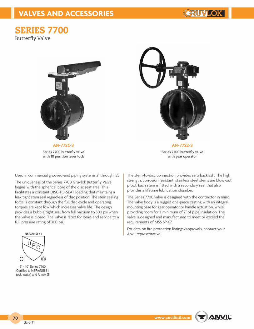
VALVES And AccESSorIES
www.anvilintl.com70
series 7700Butterfly Valve
an-7721-3Series 7700 butterfly valvewith 10 position lever lock
an-7722-3Series 7700 butterfly valve
with gear operator
Used in commercial grooved-end piping systems 2" through 12".
The uniqueness of the Series 7700 Gruvlok Butterfly Valve begins with the spherical bore of the disc seat area. This facilitates a constant DISC-TO-SEAT loading that maintains a leak tight stem seal regardless of disc position. The stem sealing force is constant through the full disc cycle and operating torques are kept low which increases valve life. The design provides a bubble tight seal from full vacuum to 300 psi when the valve is closed. The valve is rated for dead-end service to a full pressure rating of 300 psi.
The stem-to-disc connection provides zero backlash. The high strength, corrosion resistant, stainless steel stems are blow-out proof. Each stem is fitted with a secondary seal that also provides a lifetime lubrication chamber.
The Series 7700 valve is designed with the contractor in mind. The valve body is a rugged one-piece casting with an integral mounting base for gear operator or handle actuation, while providing room for a minimum of 2" of pipe insulation. The valve is designed and manufactured to meet or exceed the requirements of MSS SP-67.
For data on fire protection listings/approvals, contact your Anvil representative.
2" - 10" Series 7700Certified to NSF/ANSI 61(cold water) and Annex G
NSF/ANSI 61
GL-6.11

VALVES & AccESSorIES
Intro
duct
ion
Coup
lings
Outle
tsFi
tting
sVa
lves
&
Acce
ssor
ies
High
Pres
sure
DI-L
OK®
Nipp
les
Plai
n-En
dFi
tting
sHD
PECo
uplin
gsSo
ck-It
®
Fitti
ngs
Stai
nles
sSt
eel M
etho
dRo
ll Gr
oove
rsIn
stal
latio
n&
Ass
embl
ySp
ecia
lCo
atin
gsDe
sign
Serv
ices
Tech
nica
lDa
taM
aste
r For
mat
3 Pa
rt Sp
ecs.
Pict
oria
lIn
dex
CTS
Copp
er
Syst
em
www.anvilintl.com 71
5
4
1
3
5
6
7
7
2
series 7700Butterfly Valve
1. BODY: Ductile Iron conforming to ASTM A 536, Grade 65-45-12 Body Coating: Nylon: +230°F (+110°C) maximum service temperature
2. DISC: Ductile Iron conforming to ASTM A 536 Grades 65-45-12 Disc Encapsulation: Properties as specified in accordance with ASTM D 2000. ❏ Grade E (EPDM): Service Temperature Range -40°F to +230°F (-40°C to +110°C) Recommended for water service, dilute acids, alkalies, oil-free air and many chemical services. NOT FOR USE IN PETROLEUM SERVICES.
❏ Grade T (Nitrile): Service Temperature Range -20°F to +180°F (-29°C to +82°C) Recommended for petroleum products, air with oil vapors, vegetable oils and mineral oils. NOT FOR USE IN HOT WATER SERVICES.
3, 4. UPPER AND LOWER SHAFT: Type 416 Stainless Steel
5. O-RINGS: Compatible with disc coating
6, 7. TOP AND BOTTOM BRONzE SLEEVE BUSHINGS: 8", 10", & 12" Valve only
material specifications
* Special Options -Call an Anvil Representative for
pricing and availability.E- Silicone Free
NOTE: For operator safety, hand levers on 8" valves are limited to applications with a 25 PSI (1.7 bar) maximum pressure. For operator safety, hand levers on 10" and 12" valves are not available.
GruVLoK ButtErFLY VALVE SErIES 7700 (ordErInG InForMAtIon)
Sample Part Number 8" AN7721-3* ––>
8" A N 77 2 1 - 3*Size Body Style Body Coating Series Disc Coating Operator Stem
2" - 12" A N - Nylon 77-77XX 1 - Nitrile (Grade T) 0 - None 3 - 416 S.S.
2 - EPDM (Grade E) 1 - 10 Pos. L/Lock
2 - Gear Operator
D - Infinite Pos. w/Memory Stop
4 - Short 10 Pos. L/lock Operator
GL-6.11

VALVES And AccESSorIES
www.anvilintl.com72
series 7700Butterfly Valve
Note: 3" or 5" handwheels may be included on valves sizes 2" - 4". Contact your Anvil Rep. for additional information.
SErIES 7700 ButtErFLY VALVE dIMEnSIonS
DimensionsValve Size (ANSI/DN)
2 21⁄2 3 4 5 6 8 10 12In./mm 50 65 80 100 125 150 200 250 300
O.D. 23⁄8 27⁄8 31⁄2 41⁄2 59⁄16 65⁄8 85⁄8 103⁄4 123⁄4In./mm 60.3 73.0 88.9 114.3 141.3 168.3 219.1 273.1 323.9
A33⁄16 313⁄16 313⁄16 45⁄8 513⁄16 513⁄16 51⁄4 61⁄4 61⁄281.0 96.8 96.8 117.3 147.6 147.6 133.4 158.8 165.1
B3 33⁄16 313⁄16 41⁄4 5 51⁄2 615⁄16 8 9
75.4 80.8 96.5 108.5 126.5 138.9 175.8 202.9 229.4
C43⁄16 43⁄8 51⁄16 53⁄8 57⁄8 63⁄8 73⁄4 91⁄2 101⁄2105.9 111.3 129.0 136.7 149.4 161.8 196.9 240.3 266.7
D11⁄16 11⁄16 11⁄16 11⁄16 11⁄16 11⁄16 15⁄8 15⁄8 15⁄826.9 26.9 26.9 26.9 26.9 26.9 41.1 41.1 41.1
E7⁄16 7⁄16 7⁄16 7⁄16 7⁄16 7⁄16 3⁄4 3⁄4 3⁄4
11.1 11.1 11.1 11.1 11.1 11.1 19.1 19.1 19.1
F3 3 3 3 3 3 5 5 5
76.2 76.2 76.2 76.2 76.2 76.2 127.0 127.0 127.0
G9⁄16 9⁄16 9⁄16 9⁄16 7⁄8 7⁄8 1 11⁄4 11⁄4
14.3 14.3 14.3 14.3 22.2 22.2 25.4 31.8 31.8
H7⁄16 7⁄16 7⁄16 7⁄16 7⁄16 7⁄16 1⁄2 1⁄2 1⁄2
11.1 11.1 11.1 11.1 11.1 11.1 13.5 13.5 13.5
J- - - - - 1⁄8 13⁄8 17⁄8 23⁄4- - - - - 3.3 34.8 47.0 70.1
K3 3 3 3 3 3 5 5 5
76.2 76.2 76.2 76.2 76.2 76.2 127.0 127.0 127.0
L55⁄16 51⁄2 61⁄4 61⁄2 7 71⁄2 97⁄16 - -135.1 140.5 158.2 165.9 178.6 191.0 240.3 - -
M101⁄2 101⁄2 101⁄2 101⁄2 101⁄2 101⁄2 15 - -266.7 266.7 266.7 266.7 266.7 266.7 381.0 - -
N713⁄16 8 811⁄16 9 91⁄2 10 1415⁄16 165⁄8 2011⁄16
198.0 203.3 221.1 228.7 241.4 253.9 379.2 422.7 525.3
P4 4 4 4 4 4 81⁄16 81⁄16 115⁄8
102.1 102.1 102.1 102.1 102.1 102.1 204.5 204.5 295.4
R11⁄2 11⁄2 11⁄2 11⁄2 11⁄2 11⁄2 25⁄16 25⁄16 29⁄16
38.2 38.2 38.2 38.2 38.2 38.2 58.5 58.5 65.5
S2 2 2 2 2 2 25⁄8 25⁄8 31⁄4
51.0 51.0 51.0 51.0 51.0 51.0 66.0 66.0 83.0
T65⁄16 65⁄16 65⁄16 65⁄16 65⁄16 65⁄16 1013⁄16 1013⁄16 1313⁄16
160.3 160.3 160.3 160.3 160.3 160.3 275.3 275.3 350.3
U5 5 5 5 5 5 12 12 18
127.0 127.0 127.0 127.0 127.0 127.0 304.8 304.8 457.2
GL-6.11

VALVES & AccESSorIES
Intro
duct
ion
Coup
lings
Outle
tsFi
tting
sVa
lves
&
Acce
ssor
ies
High
Pres
sure
DI-L
OK®
Nipp
les
Plai
n-En
dFi
tting
sHD
PECo
uplin
gsSo
ck-It
®
Fitti
ngs
Stai
nles
sSt
eel M
etho
dRo
ll Gr
oove
rsIn
stal
latio
n&
Ass
embl
ySp
ecia
lCo
atin
gsDe
sign
Serv
ices
Tech
nica
lDa
taM
aste
r For
mat
3 Pa
rt Sp
ecs.
Pict
oria
lIn
dex
CTS
Copp
er
Syst
em
www.anvilintl.com 73
HEAdLoSS EQuIVALEnt LEnGtH oF PIPE
Valve Size O.D.
Equivalent Feet of Pipe* C=120
Max. Insulating ThicknessSch. 10 Sch. 30 Sch. 40
In./mm In./mm Ft./m In./mm
2 2.375 5.8 - 4.7 250 60.3 1.8 - 1.4 5021⁄2 2.875 5.1 - 3.7 21⁄265 73.0 1.6 - 1.1 653 3.500 9.6 - 7.2 280 88.9 2.9 - 2.2 504 4.500 7.5 - 5.7 21⁄2
100 114.3 2.3 - 1.7 655 5.563 7.0 - 5.6 21⁄2
125 141.3 2.1 - 1.7 656 6.625 6.1 - 4.8 21⁄2
150 168.3 1.9 - 1.5 658 8.625 6.3 5.7 - 21⁄2
200 219.1 1.9 1.7 - 6510 10.750 11.3 10.2 - 3250 273.1 3.4 3.1 - 8012 12.750 8.4 7.4 - 31⁄2300 323.9 2.6 2.3 - 90
cV VALuES
Valve Size O.D.
Disc Position (degrees open)
25° 30° 40° 50° 60° 70° 80° 90°In./mm In./mm
2 2.375 4 7 19 44 48 80 111 15850 60.3 0.3 0.5 1.3 3.0 3.3 5.5 7.7 10.9
21⁄2 2.875 9 14 34 78 84 142 196 28065 73.0 0.6 1.0 2.3 5.4 5.8 9.8 13.5 19.3
3 3.500 14 20 50 112 128 215 285 40080 88.9 1.0 1.4 3.4 7.7 8.8 14.8 19.7 27.6
4 4.500 29 41 100 239 250 420 582 826100 114.3 2.0 2.8 6.9 16.5 17.2 29.0 40.1 57.0
5 5.563 62 76 182 415 445 780 1,100 1,480125 141.3 4.3 5.2 12.5 28.6 30.7 53.8 75.8 102.0
6 6.625 96 141 325 755 809 1,370 1,920 2,678150 168.3 6.6 9.7 22.4 52.1 55.8 94.5 132.4 184.6
8 8.625 172 252 592 1,365 1,460 2,430 3,410 4,819200 219.1 11.9 17.4 40.8 94.1 100.7 167.5 235.1 332.3
10 10.750 230 328 792 1,825 1,962 3,260 4,590 6,431250 273.1 15.9 22.6 54.6 125.8 135.3 224.8 316.5 443.4
12 12.750 418 604 1,440 3,350 3,590 5,980 8,750 11,947300 323.9 28.8 41.6 99.3 231.0 247.5 412.3 603.3 823.7
series 7700Butterfly Valve Performance DataMaximum Working Pressure Rating: 300 PSI
(Commercial Applications - Sizes 2" thru 12")
* The equivalent feet of pipe is based on the Hazen and Williams formula and the flow rates typically used with each size valve.
† These values are valid for water and lubricating fluid service only. Contact Anvil for information on torques for dry and non-lubricating fluid service.* Weights may vary based on valve options selected.
2 I
NC
H V
ALV
E
2
1 /2 I
NC
H V
ALV
E
3 I
NC
H V
ALV
E
4 I
NC
H V
ALV
E
5 I
NC
H V
ALV
E
6 I
NC
H V
ALV
E
8 I
NC
H V
ALV
E
10 I
NC
H V
ALV
E
12 I
NC
H V
ALV
E
100 200 300 400 500 700 1000 2000 3000 4000 5000 7000 10000
FLOW RATE IN GALLONS PER MINUTE (GPM)
NO
MIN
AL
PR
ES
SU
RE
DR
OP
IN
PO
UN
DS
PE
R S
QU
AR
E I
NC
H (
PS
I)
5.0
4.0
3.0
2.0
1.0 0.9 0.8
0.7
0.6
0.5
0.4
0.3
0.2
0.1
PrESSurE droP (PSI) VS. (GPM)VALVE WEIGHt And torQuE VALuES
Valve Size O.D. * Approx.
Wt. Ea.Operating Pressure
50 PSIG 100 PSIG 150 PSIG 200 PSIG 300 PSIGIn./mm In./mm Lbs./Kg †Breakaway Torque (In. - Lbs) / N-m
2 2.375 5 65 72 75 80 8550 60.3 2.3 7.3 8.1 8.5 9.0 9.621⁄2 2.875 10 75 82 82 90 9465 73.0 4.5 8.5 9.3 9.3 10.2 10.63 3.500 11 75 85 95 115 12080 88.9 5.0 8.5 9.6 10.7 13.0 13.64 4.500 15 180 195 200 205 220
100 114.3 6.8 20.3 22.0 22.6 23.2 24.95 5.563 20 224 307 320 347 452
125 141.3 9.0 25.3 34.7 36.2 39.2 51.16 6.625 46 276 376 404 428 599
150 168.3 20.9 31.2 42.5 45.6 48.4 67.78 8.625 68 613 694 794 880 1,067
200 219.1 30.8 69.3 78.4 89.7 99.4 120.610 10.750 78 742 864 1,160 1,452 1,680250 273.1 35.4 83.8 97.6 131.1 164.1 189.812 12.750 91 2,220 2,633 2,917 3,210 4,200300 323.9 41.3 250.8 297.5 329.6 362.7 474.5
GL-6.11

VALVES And AccESSorIES
www.anvilintl.com74
series 7700Butterfly ValveResistance to various chemicals, as a function of temperature ˚F (Fahrenheit)
nylon coatinGCoating Condition after 18 months immersion
rESIStAncE68˚F 104˚F 140˚F 176˚F
Alcoholsbenzyl alcohol L P P Pbutanol G*** L Pethanol (pure) G*** G Lglycerine (pure) G G L Pglycol G G G Pmethanol (pure) G*** L PChlorinated solventscarbon tetrachloride Pmethyl bromide G Pmethyl chloride G Pperchloroethylene G G Ltrichloroethane L Ptrichloreothylene G LPhenols
P P P PVarious Organic Compoundsanethole Gcarbon disulphide G*** L** Pdiacetone alcohol G G*** L Pdimethyl formamide G G Lethylene chlorhydrin P Pethylene oxide G G L Pfurfurol G G*** L Pglucose G G G Gtetraethyl lead Gtetrahydrofurare G G LSalts, esters, ethersamyl acetate G G G Lbutyl acetate G G G Ldiethyl ether Gdioctylphosphate G G G Ldioctylphthalate G G G Lethyl acetate G G Gfatty acid esters G G G Gmethyl acetate G G Gmethyl sulfate G Ltributylphosphaate G G G Ltricresylphosphate GG G G LVarious Productsbeer Gcider Gcrude petroleum G G G***diesel fuel G G G***fruit juices G Gfuel-oil G G Ggreases G G G Gground nut oil G Ghigh octane gasoline G G G***kerosene (paraffin) G G G***linseed cake G G G Gmilk G G G Gmustard Gnormal gasoline G G G***oils G G G G
LEGEnd* = Slight Yellowing
** = Yellowing*** = Swelling observed
G = GoodL = LimitedP = Poor
rESIStAncE68˚F 104˚F 140˚F 176˚F
Various Products (cont’d.)solutions or emulsions of D.D.T. or lindane hudroxy-quinoline (agricultural sprays)
G
soap solution Gstearin G G Gsolvent naptha G G G***natural gas G Gturpentine G G G***vinegar Gwine GInorganic Acidschromic acid (10%) P P P Phydrochlorhic acid (1%) G L P Phydrochlorhic acid (10%) G L P Pnitric acid (all concentrations) P P P Pphosphoric acid (50%) G L P Psulphuric acid (1%) G L L Psulphuric acid (10%) G L P Psulphur trioxide L P P POther Inorganic productsagriculture sprays G Gbleach solutions L P P Pbromine P Pchlorine P P P Pfluorine P P P Phydrogen G G G Ghydrogen peroxide (20 volumes) G Lmercury G G G Goxygen G G L Pozone L P P Ppotassium permanganate (5%) P Psea water G G Gsoda water G G G Gsulphur G Gwater G G G GAldehydes & Ketonesacetaldehyde G L Pacetone G G*** L Pbenzaldehyde G L Pcyclohexanone G L Pformaldehyde (technical grade) G L Pmethylethylketone (MEK) G G L Pmethylethylketone (MIBK) G G L PHydrocarbonsacetylene G G G Gbenzene G G*** Lbutane G G Gcyclohexane G G G Ldecaline G G G LHFA (Forane®) Ghexane G G Gmethane G G Gnaphthalene G G G Lpropane G G Gstyrene G G***
rESIStAncE68˚F 104˚F 140˚F 176˚F
Hydrocarbons (cont’d.)tulene G G*** L Lxylene G G*** L LInorganic Basesammonium hydroxide (concentrated) G G G Gammonia (liquid or gas) G Glime-wash G G Gpotassium hydroxide (50%) G L P Psodium hydroxide (5%) G G Lsodium hydroxide (10%) G L Lsodium hydroxide (50%) G L P POrganic acids & anhydridesacetic acid L P P Pacetic anhydrie L P P Pcitric acid G G L Pformic acid P P P Plactic acid G G G Loleic acid G G G Loxalic acid G G L Ppicric acid L P P Ptartaric acid (saturated solution) G G G Luric acid G G G LInorganic Saltsalum G G Galuminium sulphate G G G Gammonium nitrate G G Gbarium chloride G G G G
calcium arsenate (concentrated solutions or slurries) G G G
calcium chloride G G G Gcalcium sulphate G G Lcopper sulphate G G G Gdiammonium phosphate G G Lmagnesium chloride (50%) G G G Gpotassium ferrocyanide G G Gpotassium nitrate G* L* P Ppotassium sulphate G G G Gsodium carbonate G G L Psodium chloride (saturated) G G G Gsodium silicate G G Gsodium sulphide G L Ltrisodium phosphate G G G GOrganic basesaniline (pure) L P P Pdiethanolamine (20%) G G*** G*** Lpyridine (pure) L P P Purea G G L L
GL-6.11
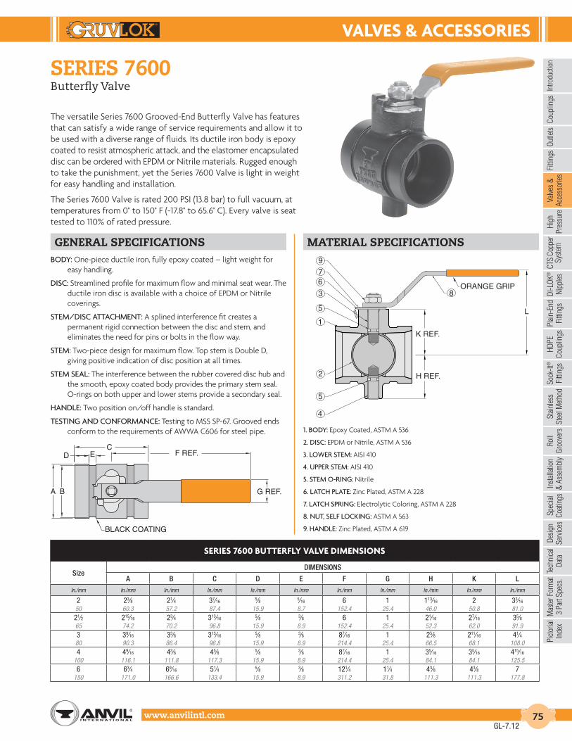
VALVES & AccESSorIES
Intro
duct
ion
Coup
lings
Outle
tsFi
tting
sVa
lves
&
Acce
ssor
ies
High
Pres
sure
DI-L
OK®
Nipp
les
Plai
n-En
dFi
tting
sHD
PECo
uplin
gsSo
ck-It
®
Fitti
ngs
Stai
nles
sSt
eel M
etho
dRo
ll Gr
oove
rsIn
stal
latio
n&
Ass
embl
ySp
ecia
lCo
atin
gsDe
sign
Serv
ices
Tech
nica
lDa
taM
aste
r For
mat
3 Pa
rt Sp
ecs.
Pict
oria
lIn
dex
CTS
Copp
er
Syst
em
www.anvilintl.com 75
series 7600Butterfly Valve
The versatile Series 7600 Grooved-End Butterfly Valve has features that can satisfy a wide range of service requirements and allow it to be used with a diverse range of fluids. Its ductile iron body is epoxy coated to resist atmospheric attack, and the elastomer encapsulated disc can be ordered with EPDM or Nitrile materials. Rugged enough to take the punishment, yet the Series 7600 Valve is light in weight for easy handling and installation.
The Series 7600 Valve is rated 200 PSI (13.8 bar) to full vacuum, at temperatures from 0° to 150° F (-17.8° to 65.6° C). Every valve is seat tested to 110% of rated pressure.
General specifications material specificationsBODY: One-piece ductile iron, fully epoxy coated – light weight for
easy handling.
DISC: Streamlined profile for maximum flow and minimal seat wear. The ductile iron disc is available with a choice of EPDM or Nitrile coverings.
STEM/DISC ATTACHMENT: A splined interference fit creates a permanent rigid connection between the disc and stem, and eliminates the need for pins or bolts in the flow way.
STEM: Two-piece design for maximum flow. Top stem is Double D, giving positive indication of disc position at all times.
STEM SEAL: The interference between the rubber covered disc hub and the smooth, epoxy coated body provides the primary stem seal. O-rings on both upper and lower stems provide a secondary seal.
HANDLE: Two position on/off handle is standard.
TESTING AND CONFORMANCE: Testing to MSS SP-67. Grooved ends conform to the requirements of AWWA C606 for steel pipe. 1. BODY: Epoxy Coated, ASTM A 536
2. DISC: EPDM or Nitrile, ASTM A 536
3. LOWER STEM: AISI 410
4. UPPER STEM: AISI 410
5. STEM O-RING: Nitrile
6. LATCH PLATE: Zinc Plated, ASTM A 228
7. LATCH SPRING: Electrolytic Coloring, ASTM A 228
8. NUT, SELF LOCKING: ASTM A 563
9. HANDLE: Zinc Plated, ASTM A 619
SErIES 7600 ButtErFLY VALVE dIMEnSIonS
SizeDIMENSIONS
A B C D E F G H K LIn./mm In./mm In./mm In./mm In./mm In./mm In./mm In./mm In./mm In./mm In./mm
2 23⁄8 21⁄4 37⁄16 5⁄8 5⁄16 6 1 113⁄16 2 33⁄16
50 60.3 57.2 87.4 15.9 8.7 152.4 25.4 46.0 50.8 81.021⁄2 215⁄16 23⁄4 313⁄16 5⁄8 3⁄8 6 1 21⁄16 27⁄16 35⁄865 74.2 70.2 96.8 15.9 8.9 152.4 25.4 52.3 62.0 91.93 39⁄16 33⁄8 313⁄16 5⁄8 3⁄8 87⁄16 1 25⁄8 211⁄16 41⁄480 90.3 86.4 96.8 15.9 8.9 214.4 25.4 66.5 68.1 108.04 49⁄16 43⁄8 45⁄8 5⁄8 3⁄8 87⁄16 1 35⁄16 35⁄16 415⁄16
100 116.1 111.8 117.3 15.9 8.9 214.4 25.4 84.1 84.1 125.56 63⁄4 69⁄16 51⁄4 5⁄8 3⁄8 121⁄4 11⁄4 43⁄8 43⁄8 7
150 171.0 166.6 133.4 15.9 8.9 311.2 31.8 111.3 111.3 177.8
9
76
3
5
1
2
5
4
8ORANGE GRIP
K REF.
H REF.
L
G REF.
F REF.C
ED
A B
BLACK COATING
GL-7.12

VALVES And AccESSorIES
www.anvilintl.com76
FIGurE 8000Gr - WEIGHt
Valve Size ANSI O.D.
WeightValve Only Valve with Gear Operator
In./DN(mm) In./mm Lbs./Kg. Lbs./Kg.
14 14 354 378350 355.6 160.6 171.516 16 428 452400 406.4 194.1 205.018 18 524 548450 457.2 237.7 248.620 20 704 728500 508.0 319.3 330.224 24 1,027 1,097600 609.6 465.8 497.6
series 8000GrButterfly ValveFor use in Grooved-End Piping Systems 14" to 24"
features• Up to 200 psig (13.8 bar) WOG (non-shock)
• Outstanding flow characteristics
• Low torque operation
• Superior flow control
• Streamline profile disc
• Suitable for HVAC applications
• Vacuum service to 29.5” (750 mm) Hg
• End-of-line service capabilities
butterfly valve performance data
PRESSURE RATINGS: 150 PSIG (10.3 bar) WOG (non-shock) 200 PSIG (13.8 bar) WOG (non-shock)Special order - available upon request.29.5” (750 mm) Hg Vacuum Service
TEMPERATURE RATINGS: Grade E (EPDM): -40°F to 230°F (-40°C to 110°C) (Service Temperature Range) Recommended for water service, dilute acids, alkaline, oil-free air and many chemical services. NOT FOR USE IN PETROLEUM SERVICES.
Grade T (Nitrile) -20°F to 180°F (Service Temperature Range) (-29°C to 82°C) Recommended for petroleum products, air with oil vapors, vegetable oils and mineral oils. NOT FOR USE IN HOT WATER SERVICES.
GL-6.11

VALVES & AccESSorIES
Intro
duct
ion
Coup
lings
Outle
tsFi
tting
sVa
lves
&
Acce
ssor
ies
High
Pres
sure
DI-L
OK®
Nipp
les
Plai
n-En
dFi
tting
sHD
PECo
uplin
gsSo
ck-It
®
Fitti
ngs
Stai
nles
sSt
eel M
etho
dRo
ll Gr
oove
rsIn
stal
latio
n&
Ass
embl
ySp
ecia
lCo
atin
gsDe
sign
Serv
ices
Tech
nica
lDa
taM
aste
r For
mat
3 Pa
rt Sp
ecs.
Pict
oria
lIn
dex
CTS
Copp
er
Syst
em
www.anvilintl.com 77
series 8000GrButterfly Valve
material specificationsBODY: Cast Iron - ASTM A 126 CL.B
EXTENSION BODY: Pipe - ASTM A 53 Steel Flange - ANSI B16.5 Forged Steel
LINER: Grade E (EPDM), GRADE T (Nitrile)
DISC: Stainless Steel - ASTM A 351 Aluminum Bronze - ASTM B 148 C95400 Ductile Iron - ASTM A 536 Grade 65-45-12
DRIVE SHAFT: Stainless Steel - ASTM A 582 Type 416 Stainless Steel - ASTM A 276 Type 316
BOTTOM SHAFT: Stainless Steel - ASTM A 582 Type 416 Stainless Steel - ASTM A 276 Type 316
RETAINING SCREW: Steel
THRUST WASHER: Acetal
PLUG: Cast Iron - ASTM A 126 CL.B
UPPER BEARING: Teflon (Reinforced)
LOWER BEARING: Teflon (Reinforced)
SErIES 8000Gr ButtErFLY VALVES - dIMEnSIonS
Valve Size ANSI O.D. A B C D E F G J K L M N P R
In./DN(mm) In./mm In./mm In./mm In./mm In./mm In./mm In./mm In./mm In./mm In./mm In./mm In./mm In./mm In./mm In./mm
14 14.000 261⁄4 131⁄4 21 21⁄4 11⁄2 2 3⁄8 x 3⁄8 6 1⁄2 131⁄16 103⁄4 5 1715⁄16 10350 356 667 337 533 57 38 51 87 152 13 332 273 127 456 25416 16.000 291⁄2 143⁄4 231⁄2 21⁄4 11⁄2 2 3⁄8 x 3⁄8 6 1⁄2 145⁄16 121⁄2 5 197⁄16 10400 406 749 375 597 57 38 51 87 152 13 364 318 127 494 25418 18.000 323⁄4 153⁄4 25 3 13⁄4 23⁄8 3⁄8 x 3⁄8 63⁄4 1⁄2 153⁄8 14 5 207⁄16 10450 457 832 400 635 76 44 60 87 171 13 391 356 127 519 25420 20.000 34 161⁄4 271⁄2 3 13⁄4 25⁄8 3⁄8 x 3⁄8 63⁄4 1⁄2 163⁄8 15 5 2015⁄16 10500 508 864 413 699 76 44 66 87 171 13 416 381 127 532 25424 24.000 393⁄8 191⁄8 32 3 21⁄4 31⁄4 1⁄2 x 1⁄2 91⁄2 13⁄16 181⁄4 163⁄4 61⁄2 243⁄8 101⁄4600 610 1,000 486 813 76 57 83 116 241 21 464 425 165 619 260
K DIA. HOLE
N DIA.
BOLTHOLE
G SIZE
OF KEY
J DIA.
E DIA.
C DIA.
A
B
D
L
M
F
R
P
POSITION INDICATOR
GEAR OPERATOR (Shown 90 ° out
of Position)
SErIES 8000Gr ButtErFLY VALVES (ordErInG InForMAtIon)
Sample Part Number18" GC-8282-6 ––>
18" G C - 8 2 8 2 6ValveSize
Body Style
Body Material
Series Seat Material
Disc Material
Operator Stem
14" - 24" G - Grooved End
C - Cast Iron
8 - 8000 1 - Nitrile 0 - Nickel Plate Ductile Iron
0 - None 6 - 416 S.S. w/ RTFE Bearing
2 - EPDM 7 - 316 S.S 2 - Gear Operator 7 - 316 S.S. w/ RTFE Bearing
8 - Bronze (Al-Brz.) 3 - Pneumatic4 - Electric5 - Spring Return Pneumatic
6 - Square Nut (with Gear Operator)
7 - Chain Wheel (with Gear)
GL-6.11
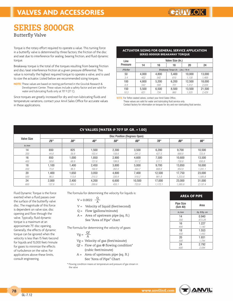
VALVES And AccESSorIES
www.anvilintl.com78
ArEA oF PIPE
Pipe Size (Sch 40) Area
In./mm Sq. ft/Sq. cm
14 0.940350 873.2916 1.227400 1,14018 1.553450 1,44320 1.931500 1,79424 2.792600 2,594
series 8000GrButterfly Valve
Torque is the rotary effort required to operate a value. This turning force in a butterfly valve is determined by three factors; the friction of the disc and seat due to interference for sealing, bearing friction, and fluid dynamic torque.
Breakaway torque is the total of the torques resulting from bearing friction and disc/seat interference friction at a given pressure differential. This value is normally the highest required torque to operate a valve, and is used to size the actuator. Listed below are recommended sizing torques.
notE: These values are based on testing performed in the Gruvlok Research & Development Center. These values include a safety factor and are valid for water and lubricating fluids only at 70° F (21° C).
Since torques are greatly increased for dry and non-lubricating fluids and temperature variations, contact your Anvil Sales Office for accurate values in these applications.
NOTE: For Teflon seated valves, contact your Anvil Sales Office. These values are valid for water and lubricating fluid service only.
Contact factory for information on torques for dry and non-lubricating fluid service.
Fluid Dynamic Torque is the force exerted when a fluid passes over the surface of the butterfly valve disc. The magnitude of this force is dependent on valve size, disc opening and flow through the valve. Typically, fluid dynamic torque is a maximum at an approximate 75° disc opening. Generally, the effects of dynamic torque can be ignored when the velocity is less than 15 feet/second for liquids and 15,000 feet/minute for gases to minimize the effects of turbulence on the valve. For applications above these limits, consult engineering.
The formula for determining the velocity for liquids is:
The formula for determining the velocity of gases:
* Flowing condition means at temperature and pressure of gas stream in the valve
V = 0.0022
V = Velocity of liquid (feet/second)
Q = Flow (gallons/minute)
A = Area of upstream pipe (sq. ft.)
See “Area of Pipe” chart
QA
Vg =
Vg = Velocity of gas (feet/minute)
Qf = Flow of gas @ flowing condition*
(cubic feet/minute)
A = Area of upstream pipe (sq. ft.)
See “Area of Pipe” Chart
QfA
ActuAtor SIZInG For GEnErAL SErVIcE APPLIcAtIonSErIES 8000Gr BrEAKAWAY torQuE
Line Pressure
Valve Size (In.)
14 16 18 20 24(PSI)/Bar Breakaway Torque (In. - Lbs.) / N-m
50 4,000 4,800 5,400 10,000 13,0003.4 452 542 610 1,130 1,469
100 4,800 5,200 6,200 12,500 18,0006.9 542 588 701 1,412 2,034
150 5,500 6,500 8,500 13,500 21,50010.3 621 734 960 1,525 2,429
cV VALuES (WAtEr @ 70°F SP. Gr. = 1.00)
Valve SizeDisc Position (Degrees Open)
25° 30° 40° 50° 60° 70° 80° 90°In./mm
14 650 825 1,500 2,300 3,500 6,200 9,700 10,500350 44.8 56.9 103.4 158.6 241.3 427.5 668.8 723.9
16 850 1,000 1,850 2,900 4,600 7,500 10,600 13,500400 58.6 68.9 127.6 199.9 317.2 517.1 730.8 930.8
18 1,100 1,400 2,450 3,800 5,000 9,700 13,850 18,000450 75.8 96.5 168.9 262.0 344.7 668.8 954.9 1,241.1
20 1,400 1,650 3,050 4,800 7,400 12,500 17,750 23,000500 96.5 113.8 210.3 330.9 510.2 861.8 1,223.8 1,585.8
24 2,000 2,400 4,200 6,600 10,500 17,000 23,000 31,000600 137.9 165.5 289.6 455.1 723.9 1,172.1 1,585.8 2,137.4
GL-7.12

VALVES & AccESSorIES
Intro
duct
ion
Coup
lings
Outle
tsFi
tting
sVa
lves
&
Acce
ssor
ies
High
Pres
sure
DI-L
OK®
Nipp
les
Plai
n-En
dFi
tting
sHD
PECo
uplin
gsSo
ck-It
®
Fitti
ngs
Stai
nles
sSt
eel M
etho
dRo
ll Gr
oove
rsIn
stal
latio
n&
Ass
embl
ySp
ecia
lCo
atin
gsDe
sign
Serv
ices
Tech
nica
lDa
taM
aste
r For
mat
3 Pa
rt Sp
ecs.
Pict
oria
lIn
dex
CTS
Copp
er
Syst
em
www.anvilintl.com 79
MEMorY StoPSize A
In./DN(mm) In./mm1⁄4 - 3⁄8 - 1⁄2 3.88 - 10 - 15 97.0
3⁄4 - 1 4.820 - 25 121.5
11⁄4 - 11⁄2 5.932 - 40 151.0
2 6.450 162.0
StEM EXtEnSIon (BrASS)Size A B
In./DN(mm) In./mm In./mm1⁄4 - 3⁄8 - 1⁄2 3.8 2.48 - 10 - 15 97.0 60.5
3⁄4 - 1 4.8 2.620 - 25 121.5 67.0
11⁄4 - 11⁄2 5.9 2.632 - 40 151.0 67.0
2 6.4 2.650 162.0 67.0
21⁄2 - 3 8.0 2.665 - 80 203.2 67.0
4 10.2 2.6100 259.1 67.0
fiG. 171n & fiG. 1715International Brass Ball Valves
material specificationsBODY: Brass CW 617N UNI EN 12165RETAINER: Brass CW 617N UNI EN 12165BALL: Brass CW 617N UNI EN 12165STEM: Brass CW 614N UNI EN 12164SEAT RING: PTFEPACKING: PTFEPACKING NUT: Steel 6SPACKING GLAND: Brass CW 614N UNI EN 12164FRICTION WASHER: PTFESTEM O-RING: NBRHANDLE: Steel, Zinc Plated to 2", Aluminum to 4"HANDLE COVER: Yellow PVC Coated to 2", Yellow Enamel to 4"HANDLE NUT: Steel, Zinc Plated
AVAILABLE OPTIONS*LEVER HANDLE: 1⁄4" - 4"LOCK DEVICE: 1⁄4" - 4"MEMORY STOP: 1⁄4" - 2"STEM EXTENSION: 1⁄4" - 4"“T” HANDLE: 1⁄4" - 1"* Not all options available for all sizes. Please contact your Anvil Representative for assistance.
“t” HAndLESize A B
In./DN(mm) In./mm In./mm1⁄4 - 3⁄8 - 1⁄2 2.0 1.088 - 10 - 15 50 27.5
3⁄4 - 1 2.5 1.3020 - 25 64 33.0
The Anvil Figure 171N and 1715 Brass Ball Valves have a rugged, dependable design, meeting rigid specification for world wide use. Every valve is individually tested in an open and closed position at 80 psi (5.5 bar). The two piece 1715 and 171N full port design are available in sizes 1⁄4" - 4". A “T” handled version of the 171N is also available as Figure 171N-T in sizes 3⁄8" - 1". All valves conform to MSS-SP-110, MSS-SP-25 and Federal Specification WW-V-35B Type II, Class A Style 3.
Features of these valves include triple stem seal, hard chrome plated ball, blowout proof stem, adjustable packing gland, a bubble tight shut off and a floating ball for an economical solution for residential, commercial and industrial applications.
Anvil’s Brass Ball Valves are available in full port threaded end (Figure 171N), and full port soldered end (Figure 1715). Size Range: 1⁄4" - 4"
For Listings/Approval Details and Limitations,visit our website at www.anvilintl.com orcontact an Anvil® Sales Representative.
Pressure Rating from full vacuum to:600 psi (41.4 bar) WOG150 psi (10.3 bar) WSP
For Listings/Approval Details and Limitations,visit our website at www.anvilintl.com orcontact an Anvil® Sales Representative.For Listings/Approval Details and Limitations, visit our website
at www.anvilintl.com or contact an Anvil® Sales Representative.
UL Listed Sizes:171N 1/4 - 2" (250psi)
FM Approved Sizes:171N 1/4 - 2" (600psi)
Figure 171N
LocK dEVIcESize A
In./DN(mm) In./mm1⁄4 - 3⁄8 - 1⁄2 1.288 - 10 - 15 32.5
3⁄4 - 1 1.5720 - 25 40.0
11⁄4 - 11⁄2 1.9132 - 40 48.5
2 1.9550 49.5
21⁄2 - 3 3.9065 - 80 99.1
4 4.10100 104.1
171N
GL-7.12

VALVES And AccESSorIES
www.anvilintl.com80
dIMEnSIonS
Valve Code Size Port
Dia. A C D Cv Approx. Wt. Ea.
In./mm In./mm In./mm In./mm In./mm Lbs./Kg
171N FULL PORT
THREADED END
1⁄4 3⁄8 2 37⁄8 13⁄4 6 0.38 10 51 98 45 0.1
3⁄8 3⁄8 2 37⁄8 13⁄4 7 0.310 10 51 98 45 0.11⁄2 9⁄16 27⁄16 37⁄8 17⁄8 19 0.415 14 62 98 48 0.23⁄4 3⁄4 211⁄16 413⁄16 21⁄4 35 0.720 19 68 122 57 0.3
1 15⁄16 31⁄16 413⁄16 27⁄16 50 1.025 24 78 122 62 0.5
11⁄4 11⁄4 37⁄16 6 31⁄16 104 2.032 32 87 152 78 0.9
11⁄2 19⁄16 37⁄8 6 35⁄16 268 3.140 40 98 152 84 1.4
2 115⁄16 45⁄16 63⁄8 313⁄16 309 4.250 49 110 162 97 1.9
21⁄2 29⁄16 59⁄16 81⁄16 5 629 8.065 65 141 205 127 3.7
3 31⁄8 67⁄16 85⁄16 57⁄16 1018 12.080 79 164 205 138 5.9
4 315⁄16 75⁄8 101⁄4 65⁄16 1622 22.0100 100 194 260 160 10.0
1715 FULL PORT
SOLDERED END
1⁄2 9⁄16 21⁄2 37⁄8 17⁄8 19 0.515 14 64 98 48 0.23⁄4 3⁄4 3 413⁄16 25⁄16 35 0.720 19 76 122 59 0.3
1 1 39⁄16 413⁄16 21⁄2 50 1.125 25 91 122 64 0.5
11⁄4 11⁄4 41⁄16 6 31⁄8 104 2.032 32 103 152 79 0.9
11⁄2 19⁄16 49⁄16 6 33⁄8 268 2.740 40 116 152 86 1.2
2 115⁄16 57⁄16 67⁄16 311⁄16 309 3.950 49 138 164 94 1.8
21⁄2 29⁄16 67⁄8 81⁄16 5 629 9.465 65 175 205 127 4.3
3 31⁄8 83⁄16 81⁄16 57⁄16 1018 14.580 79 208 205 138 6.6
4 315⁄16 105⁄16 101⁄4 65⁄16 1622 24.7100 100 262 260 160 11.2
fiG. 171n & fiG. 1715International Brass Ball Valves
pressure vs. temperature
NOTES
1. Dimensions of solder joint ends conform to ANSI B16.22. Solder end valves are designed to be used with solders not exceeding a melting point of 470°F/250°C. Higher temperatures may damage the seal material.
2. For solder joint valves, the pressure/temperature rating is dependent on the solder material used. Please refer to the limitations listed in ANSI B16.18.
3. Rate of Flow Calculations for liquids: To determine the flow rate of a liquid passing through a valve, use the following formula:
Where: QL = flow of liquid in gallons per minute (GPM) CV = flow coefficient ∆P = pressure drop (PSI) SL = specific gravity of liquid
TEMPERATURE
PR
ES
SU
RE
PSIG BAR
45
40
30
20
10
0 0
0 100 150 200 250 °C 50
5 100 150 200 250 300 350 400 450 500° F-20
-28
700
600
500
400
300
200
100
0
A
OPO R T
C
D
GL-7.12

VALVES & AccESSorIES
Intro
duct
ion
Coup
lings
Outle
tsFi
tting
sVa
lves
&
Acce
ssor
ies
High
Pres
sure
DI-L
OK®
Nipp
les
Plai
n-En
dFi
tting
sHD
PECo
uplin
gsSo
ck-It
®
Fitti
ngs
Stai
nles
sSt
eel M
etho
dRo
ll Gr
oove
rsIn
stal
latio
n&
Ass
embl
ySp
ecia
lCo
atin
gsDe
sign
Serv
ices
Tech
nica
lDa
taM
aste
r For
mat
3 Pa
rt Sp
ecs.
Pict
oria
lIn
dex
CTS
Copp
er
Syst
em
www.anvilintl.com 81
PRESSURE-RATING: 740 psig CWP (51 bar) in ASTM A 395 Ductile Iron
series 7500Ball-valves
The Series 7500 grooved-end ball valve line consists of a 2" to 6" standard port, two piece design, and is available in configurations to address a broad spectrum of application requirements.
The Series 7500 has generous factors of safety for pressure retention and stem torsional strength. In addition, it has a blow-out proof stem design, low operating torque, and
high Cv.
The Series 7500 is compliant with NACE MR01-75 when stainless steel trim is specified.
Grooved ends conform to the requirements of AWWA C606 for steel pipe.
For special configurations, contact your Anvil representative.
For stainless steel, see the stainless steel section.
fiGure 7500 material specifications
DUCTILE IRON/CARBON STEEL
BODY: Ductile Iron ASTM A 395
ENDPLATE: Ductile Iron ASTM A 395
BALL: Carbon Steel Chrome Plated
STEM: Carbon Steel Chrome Plated
THRUST WASHER: RTFE
STEM SEAL: Flouroelastomer
RETAINING RING: Carbon Steel
HANDLE: Carbon Steel Zinc Plated
HANDLE NUT: Carbon Steel Zinc Plated
SEAT: RTFE
BODY SEAL: Flouroelastomer
LOCK PLATE*: 300 Series Stainless Steel
* Optional
DUCTILE IRON/STAINLESS STEEL
BODY: Ductile Iron ASTM A 395
ENDPLATE: Ductile Iron ASTM A 395
BALL: Stainless Steel ASTM A 351 Grade CF8M
STEM: 316 Stainless Steel
THRUST WASHER: RTFE
STEM SEAL: Flouroelastomer
RETAINING RING: Carbon Steel
HANDLE: Carbon Steel Zinc Plated
HANDLE NUT: 300 Series Stainless Steel
SEAT: RTFE
BODY SEAL: Flouroelastomer
LOCK PLATE*: 300 Series Stainless Steel
* Optional
GL-6.11

VALVES And AccESSorIES
www.anvilintl.com82
series 7500Ball-valves
* Bare Stem
6" is available bare stem or with gear actuator.
7500 BALL VALVE
Size ANSI O.D.
Dimensions Approx. Wt. Ea.A B C D E F Cv
In./DN(mm) In./mm In./mm In./mm In./mm In./mm In./mm In./mm Lbs./Kg
2 2.375 51⁄2 23⁄4 81⁄4 313⁄16 115⁄16 41⁄8 165 850 60.3 140 70 209 81 49 105 3.6
3 3.500 63⁄4 33⁄8 10 413⁄16 27⁄8 413⁄16 310 1880 88.9 171 85 254 122 74 121 8.2
4 4.500 81⁄4 41⁄8 16 65⁄16 313⁄16 6 815 38100 114.3 210 105 406 176 97 152 17.2
6 * 6.625 101⁄8 51⁄16 28 87⁄16 511⁄16 75⁄8 1500 106150 168.3 257 128 711 215 144 194 48.1
7500 BALL VALVE WItH GEAr ActuAtor
Size ANSI O.D.
Dimensions Approx. Wt. Ea.A B C D E F G H J K L
In./DN(mm) In./mm In./mm In./mm In./mm In./mm In./mm In./mm In./mm In./mm In./mm In./mm In./mm Lbs./Kg
6 6.625 65⁄8 41⁄4 87⁄16 51⁄2 101⁄4 51⁄16 81⁄8 12 131⁄2 113⁄16 1 9.6150 168.3 168.7 107.4 214.6 140.5 260.4 128.0 206.4 304.8 342.9 45.2 25.4 4.4
A
F
D
ValvePipe O.D.
E
CB
OPEN
CLOSED
AB
E
H
G
J
B
F
CL
K
D
6" - 7500Ball Valve withGear Actuator
SErIES 7500 BALL VALVES (ordErInG InForMAtIon)
Sample Part Number4" GI-7512-1 ––>
4" G I - 75 1 2 - 1Size Configuration Body/End
MaterialSeries Ball and Stem
MaterialSeat
Material Operator
2" - 6" G - 2 Way Grooved End
I - Ductile Iron ASTM A395
75 - 7500 1 - Chrome Plated Carbon Steel
2 - RTFE / Flouroelastomer
1 - 2 Position Handle
2 - 316 Stainless Steel Special Requirements
2 - 2 Position Locking Handle
X - Write on Order 3 - Bare Stem
4 - Gear Actuator (6" Only)
GL-6.11

VALVES & AccESSorIES
Intro
duct
ion
Coup
lings
Outle
tsFi
tting
sVa
lves
&
Acce
ssor
ies
High
Pres
sure
DI-L
OK®
Nipp
les
Plai
n-En
dFi
tting
sHD
PECo
uplin
gsSo
ck-It
®
Fitti
ngs
Stai
nles
sSt
eel M
etho
dRo
ll Gr
oove
rsIn
stal
latio
n&
Ass
embl
ySp
ecia
lCo
atin
gsDe
sign
Serv
ices
Tech
nica
lDa
taM
aste
r For
mat
3 Pa
rt Sp
ecs.
Pict
oria
lIn
dex
CTS
Copp
er
Syst
em
www.anvilintl.com 83
FIGurE 400G GrooVEd-End SILEnt cHEcK VALVE
Valve Size O.D. Model A B Cv
Flow *Approx. Wt. Each
In./mm In./mm Number In./mm In./mm Lbs./Kg
2 2.375 402G 6 6 66 1250 60.3 152 152 1,676 5.4
21⁄2 2.875 4025G 61⁄4 7 88 1565 73.0 159 178 2,235 6.8
3 3.500 403G 67⁄16 71⁄2 130 2080 88.9 164 191 3,302 9.1
4 4.500 404G 81⁄8 9 228 36100 114.3 206 229 5,791 16.3
5 5.563 405G 111⁄4 10 350 50125 141.3 286 254 8,890 22.7
6 6.625 406G 121⁄4 11 520 68150 168.3 311 279 13,208 30.8
8 8.625 408G 133⁄4 131⁄2 900 140200 219.1 349 343 22,860 63.5
10 10.750 410G 16 16 1,450 198250 273.1 406 406 36,830 89.8
MAX. non-SHocK WorKInG PSI125# AnSI B16.1 FLAnGE rAtInG
Size Temperature
2" - 10"
150˚F 200˚F65°C 90°C
200 PSI 190 PSI13.8 bar 13.1 bar
material specifications
fiG. 400GGrooved-End Silent Check ValveAvailable in Sizes 2" thru 10"
The 400G is a center guided, spring loaded, silent check valve. Designed and engineered for silent operation with low head loss, the valve disc will close prior to the reversal of flow, thereby preventing or minimizing water hammer and damaging shock.
• The 400G can be used in any HVAC, industrial or commercial grooved piping systems.
• The valve is designed for liquid service with any pipe orientation, flow up or down.
• Bronze metal seats are standard, with Stainless Steel or resilient seats available as an option.
• Flow coefficients for this valve are some of the lowest in the industry and are listed for each size on the drawing.
NOTE: Valve is designed for liquid service only. Install 3 to 4 pipe diameters downstream from pump discharge or elbows to avoid flow turbulence.
STANDARD MATERIALS:Cast Iron body ASTM A 48, Class 35Bronze Disc and Seat ASTM B 584 Alloy 838Ductile Iron Grooved-Ends ASTM A 395
OPTIONAL TRIM MATERIALS:Bronze with Nitrile seatsStainless Steel seatsStainless with Nitrile seats
1. BODY: Cast Iron ASTM A 48, Class 35
2. SEAT: Bronze ASTM B 584, Copper Alloy 838
3. PLUG: Bronze ASTM B 584, Copper Alloy 838
4. SPRING: Stainless Steel T304, ASTM A 313
5. BUSHING: Bronze ASTM B 584, Copper Alloy 836
6. SCREWS: Stainless Steel T304, ASTM A 276
7. GROOVED-END: Ductile Iron ASTM A 395
8. GASKET: Non Asbestos
For gasket grade recommendations see the Technical Data section
9. BOLTS: Carbon Steel
Other materials and resilient seats are available...
contact your Anvil representative. A
B
9
1
2
3
4
5
6
78
8
Cv FLOW
* Flow coefficient is the number of U.S. gallons/minute of 60˚ F (16˚ C) water that will flow through a valve with 1 psi (0.069 bar) of pressure drop across the valve.
GL-6.11

VALVES And AccESSorIES
www.anvilintl.com84
series 7800Check ValvesFor use in Grooved-End Piping Systems
The Gruvlok Series 7800 Check Valve is a compact, cost effective valve offering low pressure-drop, non-slam performance. The Series 7800 Check Valve assembly is lighter and faster to install, and costs less than flanged and wafer valve assemblies.
In the fully open position the Series 7800 swing clapper is held tightly against the valve body, out of the flow stream, to provide maximum flow area and prevention of clapper flutter. The clapper design produces quick, non-slam closure before flow reversal can occur, while meeting FM requirements for an anti-water hammer valve rating.
Each valve is hydrostatically tested for leak tightness to 500 PSI. The clapper-seat design permits leak free sealing of back pressures in service conditions ranging from 300 PSI (20.7 bar) to as low as 1 PSI (0.07 bar) (head pressure: 28").
performance:Pressure Rating: Commercial Applications - Sizes 2" thru 12" inclusive, 300 psi (20.7 bar) maximum working pressure.
material specifications
BODY: Ductile iron conforming to ASTM A 536, Grade 65-45-12
COATING: Rust inhibiting paint on exterior and interior – color: black enamel
CLAPPER: 2”- 5” Type 304 or 302 stainless steel to ASTM A 167 6"-12" Ductile iron conforming to ASTM A 536, Grade 65-45-12
CLAPPER FACING:Grade E EPDM: -40° to 230°F (-40° to 110°C) Service Temperature Range
Recommended for water service, dilute acids, alkaline, oil-free air and many chemical services. NOT FOR USE IN PETROLEUM SERVICES.
Grade T Nitrile: -20° to 180°F (-29° to 80°C) Service Temperature Range Recommended for petroleum products, air with oil vapors, vegetable oils and mineral oils. NOT FOR USE IN HOT WATER SERVICES.
SEAT RING: Type 304 stainless steel to ASTM A 123, ASTM A 213, ASTM A 312 or ASTM A 269
SPRING: Type 302 stainless steel to ASTM A 313
HINGE PIN: Type 304 or 302 stainless steel to ASTM A 580
HINGE PIN BUSHINGS: Sintered bronze to ASTM B 438
HINGE PIN PLUGS & DRAIN PLUGS: Cast iron to ASTM A 126 Class A
Spring
Bushings (2)
Hinge Pin
Hinge Pin Plug (2) DrainConnections
ClapperAssembly
Seat Ring
Body
For Listings/Approval Details and Limitations,visit our website at www.anvilintl.com orcontact an Anvil® Sales Representative.
GL-7.12

VALVES & AccESSorIES
Intro
duct
ion
Coup
lings
Outle
tsFi
tting
sVa
lves
&
Acce
ssor
ies
High
Pres
sure
DI-L
OK®
Nipp
les
Plai
n-En
dFi
tting
sHD
PECo
uplin
gsSo
ck-It
®
Fitti
ngs
Stai
nles
sSt
eel M
etho
dRo
ll Gr
oove
rsIn
stal
latio
n&
Ass
embl
ySp
ecia
lCo
atin
gsDe
sign
Serv
ices
Tech
nica
lDa
taM
aste
r For
mat
3 Pa
rt Sp
ecs.
Pict
oria
lIn
dex
CTS
Copp
er
Syst
em
www.anvilintl.com 85
FLoW dAtA - FrIctIon LoSS (Ft. oF PIPE)
Valve Size O.D.C=100 C=120
Sch. 10 Sch. 30 Sch. 40 Sch. 10 Sch. 30 Sch. 40In./mm In./mm Ft./m Ft./m Ft./m Ft./m Ft./m Ft./m
2 2.375 10 — 8 14 — 1150 60.3 3.0 — 2.4 4.3 — 3.4
21⁄2 2.875 14 — 10 20 — 1565 73.0 4.3 — 3.0 6.1 — 4.6
3 3.500 17 — 12 23 — 1780 88.9 5.2 — 3.7 7.0 — 5.2
4 4.500 17 — 13 23 — 18100 114.3 5.2 — 4.0 7.0 — 5.5
5 5.563 14 — 11 20 — 15125 141.3 4.3 — 3.4 6.1 — 4.6
6 6.625 23 — 19 33 — 26150 168.3 7.0 — 5.8 10.1 — 7.9
8 8.625 35 32 30 50 45 43200 219.1 10.7 9.8 9.1 15.2 13.7 13.1
10 10.750 28 25 24 40 36 34250 273.1 8.5 7.6 7.3 12.2 11.0 10.4
12 12.750 31 28 26 44 39 37300 323.9 9.4 8.5 7.9 13.4 11.9 11.3
series 7800Check ValvesFor use in Grooved-End Piping Systems
FLoW dAtA:
The approximate frictionlosses, based on the Hazen andWilliams formula, expressedin equivalent length of pipe isgiven below. The friction losseshave been calculated on thebasis of flow rates typicallyused with each size valve.
IMPORTANT NOTE:Check valve life may be shortened and system damage may occur if check valves are installed too close to a source of unstable flow. Check valves must be installed at a reasonable distance away from pumps, elbows, expanders, reducers or other similar devices. Sound piping practices dictate a minimum of five (5) times the pipe diameter for general use. Distances between three (3) and five (5) diameters are allowable provided the flow velocity is less than 8 feet per second. Distances less than 3 diameters are not recommended.This valve may be installed vertically or horizontally. In a horizontal installation, the hinge pin is to be located on top.Not for use in copper systems.
100 200 300 400 500 700 1000 2000 3000 4000 5000 7000 10000
1.0
1.5
0.9 0.8 0.7
0.6
0.5
2.0
3.0
4.0
5.0
6.0 7.0 8.0 9.0
1.0
1.5
0.9 0.8 0.7
0.6
0.5
2.0
3.0
4.0
5.0
6.0 7.0 8.0 9.0
NO
MIN
AL P
RES
SUR
E D
RO
P IN
PO
UN
DS
PER
SQ
UAR
E IN
CH (P
SI)
NO
MIN
AL P
RES
SUR
E D
RO
P IN
PO
UN
DS
PER
SQ
UAR
E IN
CH (P
SI)
FLOW RATE IN GALLONS PER MINUTE (GPM)
Friction Loss Series 7800 Check Valve (Water at 65˚F)
2" Va
lve
2 1/
2" V
alve
3" V
alve
4" V
alve
5" V
alve
6" V
alve
8" V
alve
12" V
alve
10" V
alve
GL-7.12

VALVES And AccESSorIES
www.anvilintl.com86
FIGurE 7800 cHEcK VALVE
Nominal Size O.D.
Nominal Dimensions Approx. Wt. Ea.A B C D E F G
In./DN(mm) In./mm In./mm In./mm In./mm In./mm In./mm In./mm In./mm Lbs./Kg.
2 2.375 63⁄4 23⁄8 17⁄16 13⁄4 41⁄2 33⁄16 43⁄8 7.550 60.3 171 60 36 44 114 81 111 3.4
21⁄2 2.875 71⁄4 27⁄16 19⁄16 13⁄4 313⁄16 35⁄8 41⁄2 10.565 73.0 184 61 39 44 96 92 114 4.8
3 3.500 73⁄4 25⁄8 2 13⁄16 41⁄16 311⁄16 415⁄16 11.580 88.9 197 67 51 46 103 93 125 5.2
4 4.500 81⁄8 31⁄8 21⁄4 21⁄2 51⁄16 41⁄4 6 13.5100 114.3 206 79 57 64 128 108 152 6.1
5 5.563 93⁄4 31⁄2 23⁄4 27⁄16 513⁄16 45⁄8 63⁄4 19.0125 141.3 248 89 70 61 147 117 171 8.6
6 6.625 123⁄4 41⁄4 35⁄16 31⁄8 61⁄4 63⁄4 81⁄2 33.5150 168.3 324 108 84 79 159 171 216 15.2
8 8.625 143⁄8 51⁄16 315⁄16 4 515⁄16 8 101⁄4 59.0200 219.1 365 128 100 102 150 203 260 26.8
10 10.750 18 65⁄16 415⁄16 49⁄16 67⁄8 93⁄16 1211⁄16 130.0250 273.1 457 160 125 115 175 233 322 59.0
12 12.750 21 75⁄16 6 51⁄16 71⁄4 103⁄8 143⁄4 183.0300 323.9 533 185 152 128 184 264 375 83.0
series 7800Check ValvesFor use in Grooved-End Piping Systems
* Contact an Anvil representative for more information.
material specifications
G
Hinge Pin Plug
1/2" NPT
1/2"NPT
Lifting Eyebolt(10" and 12" Valves Only)
A
F
BC
ED
SErIES 7800 cHEcK VALVES (ordErInG InForMAtIon)
Sample Part Number4" 7811––>
4" 78 1 1 XSize Series Clapper Facing Material Body Finish Special Configuration
2" - 12" 78 - 7800 1 - EPDM (Std) 1 - Painted (Std) 2 - Other*
2 - Nitrile (Std)
GL-7.12

VALVES & AccESSorIES
Intro
duct
ion
Coup
lings
Outle
tsFi
tting
sVa
lves
&
Acce
ssor
ies
High
Pres
sure
DI-L
OK®
Nipp
les
Plai
n-En
dFi
tting
sHD
PECo
uplin
gsSo
ck-It
®
Fitti
ngs
Stai
nles
sSt
eel M
etho
dRo
ll Gr
oove
rsIn
stal
latio
n&
Ass
embl
ySp
ecia
lCo
atin
gsDe
sign
Serv
ices
Tech
nica
lDa
taM
aste
r For
mat
3 Pa
rt Sp
ecs.
Pict
oria
lIn
dex
CTS
Copp
er
Syst
em
www.anvilintl.com 87
FIGurE GBV-G GrooVEd-End StrAIGHt BALAncInG VALVESductILE Iron, GrooVEd-End or FLAnGEd-End StrAIGHt
Nominal Size O.D. A B
Open C E FFlange Diameter Approx.
Wt. EachG Flange 125#
G Flange 250#
In./DN(mm) In./mm In./mm In./mm In./mm In./mm In./mm In./mm In./mm Lbs./Kg
21⁄2 2.875 12 95⁄8 23⁄4 1 29⁄16 7 71⁄2 25
65 73.0 305 244 70 25 65 178 191 11.3
3 3.500 12 101⁄2 27⁄16 1 3 71⁄2 81⁄4 28
80 88.9 305 267 61 25 76 191 210 12.7
4 4.500 14 109⁄16 3 11⁄4 37⁄16 91⁄4 10 41
100 114.3 356 268 76 32 87 235 254 18.6
5 5.563 171⁄2 131⁄16 35⁄8 11⁄4 415⁄16 10 11 90
125 141.3 445 331 92 32 125 254 279 40.8
6 6.625 2011⁄16 133⁄4 47⁄16 2 57⁄8 11 121⁄2 130
150 168.3 525 349 112 51 149 279 318 59.0
8 8.625 283⁄16 245⁄8 511⁄16 21⁄4 77⁄8 131⁄2 15 310
200 219.1 716 625 144 57 200 343 381 140.6
10 10.750 30 261⁄2 69⁄16 21⁄4 915⁄32 16 171⁄2 460
250 273.1 762 673 166 57 240 406 445 208.7
12 12.750 381⁄16 287⁄16 75⁄8 21⁄4 125⁄8 19 201⁄2 870
300 323.9 966 722 194 57 321 483 521 394.6
Gbv-G, Gbv-a & Gbv-fBalancing ValvesDuctile Iron ASTM A536, Grade 65-45-12
The Series GBV is a multi-turn, Y-style globe valve designed for accurate determination and control of fluid flow to circuits requiring precise balancing.
Max. Working Pressure 300 PSI / 20.7 bar (PN20)
Max. Working Temperature 300°F (150°C)
features & benefits material specifications• Pressure differential ports on both sides of the valve
• Convertible design, straight to 90° angle by removing and replacing four set screws
• Positive shutoff for equipment servicing
• Multi-turn adjustment
• Ergodynamically designed handwheel
• Micrometer type adjustment scale
• Tamper-proof hidden memory stop
BODY, BONNET: Ductile Iron ASTM A536, Grade 65-45-12
STEM & DISC: Brass Alloy B16
ELASTOMERS: EPDM
HANDWHEEL: Reinforced Nylon; ABS
Gbv-G – Balancing Valve2 1⁄2" to 12" Ductile Iron, Grooved-End or Flanged-End Straight
Straight Shown
GB
FE
C
A
NOTE: Grooved-Ends are for connection of components with dimensions conforming to Gruvlok® standard grooved specifications for IPS pipe.
GL-7.12

VALVES And AccESSorIES
www.anvilintl.com88
FIGurE GBV-A GrooVEd-End AnGLE BALAncInG VALVESductILE Iron, GrooVEd-End or FLAnGEd-End AnGLE
Nominal Size O.D. A B
Open C D E FFlange Diameter Approx.
Wt. EachG Flange 125#
G Flange 250#
In./DN(mm) In./mm In./mm In./mm In./mm In./mm In./mm In./mm In./mm In./mm Lbs./Kg
21⁄2 2.875 73⁄8 95⁄8 23⁄4 45⁄8 1 29⁄16 7 71⁄2 25
65 73.0 187 244 70 117 25 65 178 191 11.3
3 3.500 83⁄16 101⁄2 27⁄16 37⁄8 1 3 71⁄2 81⁄4 28
80 88.9 213 267 61 98 25 76 191 210 12.7
4 4.500 95⁄8 109⁄16 3 43⁄8 11⁄4 37⁄16 91⁄4 10 41
100 114.3 244 268 76 111 32 87 235 254 18.6
5 5.563 12 131⁄16 35⁄8 51⁄2 11⁄4 415⁄16 10 11 90
125 141.3 305 331 92 140 32 125 254 279 40.8
6 6.625 141⁄8 133⁄4 47⁄16 65⁄8 2 57⁄8 11 121⁄2 130
150 168.3 359 349 112 168 51 149 279 318 59.0
8 8.625 1815⁄16 245⁄8 511⁄16 93⁄16 21⁄4 77⁄8 131⁄2 15 310
200 219.1 481 625 144 233 57 200 343 381 140.6
10 10.750 205⁄16 261⁄2 69⁄16 93⁄4 21⁄4 915⁄32 16 171⁄2 460
250 273.1 515 673 166 248 57 240 406 445 208.7
12 12.750 241⁄16 287⁄16 75⁄8 14 21⁄4 125⁄8 19 201⁄2 870
300 323.9 611 722 194 356 57 321 483 521 394.6
Gbv-G, Gbv-a & Gbv-fBalancing ValvesDuctile Iron, Grooved-End and Cast Bronze, Solder & Threaded GBV
Gbv-a – Balancing Valve21⁄2" to 12" Ductile Iron, Grooved-End or Flanged-End Angle
G
B
F
E
CA
D
NOTE: Grooved-Ends are for connection of components with dimensions conforming to Gruvlok® standard grooved specifications for IPS pipe.See www.anvilintl.com for installation instructions and flow data.
GL-7.12

VALVES & AccESSorIES
Intro
duct
ion
Coup
lings
Outle
tsFi
tting
sVa
lves
&
Acce
ssor
ies
High
Pres
sure
DI-L
OK®
Nipp
les
Plai
n-En
dFi
tting
sHD
PECo
uplin
gsSo
ck-It
®
Fitti
ngs
Stai
nles
sSt
eel M
etho
dRo
ll Gr
oove
rsIn
stal
latio
n&
Ass
embl
ySp
ecia
lCo
atin
gsDe
sign
Serv
ices
Tech
nica
lDa
taM
aste
r For
mat
3 Pa
rt Sp
ecs.
Pict
oria
lIn
dex
CTS
Copp
er
Syst
em
www.anvilintl.com 89
ModEL: GBV-t 1⁄2" - 2"
Model Nominal Size A B C Approx.
Wt. Ea.In./DN(mm) In./mm In./mm In./mm Lbs./Kg
GBV050VT 1⁄2" 3 45⁄8 23⁄4 1.115 80 117 70 0.5
GBV075VT 3⁄4" 31⁄4 47⁄8 23⁄4 1.220 83 125 70 0.6
GBV100VT 1" 313⁄16 51⁄4 23⁄4 1.925 97 135 70 0.8
GBV125VT 11⁄4" 45⁄16 55⁄8 23⁄4 2.332 110 143 70 1.1
GBV150VT 11⁄2" 51⁄16 57⁄8 23⁄4 3.540 129 150 70 1.6
GBV200VT 2" 6 611⁄16 23⁄4 6.050 153 170 70 2.5
ModEL: GBV-S 1⁄2" - 2"
Model Nominal Size A B C Approx.
Wt. Ea.In./DN(mm) In./mm In./mm In./mm Lbs./Kg
GBV050VS 1⁄2" 33⁄16 49⁄16 23⁄4 1.115 81 116 70 0.5
GBV075VS 3⁄4" 39⁄16 49⁄16 23⁄4 1.120 93 118 70 0.5
GBV100VS 1" 41⁄4 415⁄16 23⁄4 1.725 108 126 70 0.8
GBV125VS 11⁄4" 415⁄16 53⁄8 23⁄4 2.332 125 137 70 1.0
GBV150VS 11⁄2" 511⁄16 55⁄8 23⁄4 3.240 144 142 70 1.5
GBV200VS 2" 7 63⁄8 23⁄4 5.450 179 162 70 2.5
Gbv-s & Gbv-tFive Turn Circuit Balancing ValvesSolder (GBV-S) & NPT Threaded (GBV-T)
The Series GBV is a multi-turn, Y-style globe valve designed for accurate determination and control of fluid flow to circuits requiring precise balancing.
• Multi-turn adjustment
• Pressure differential ports on both sides of the valve
• Positive shutoff for equipment servicing
• Micrometer type handwheel adjustment
• Tamper-proof memory stop
• Precision instrument function and performance
• Easiest and fastest field balancing
features & benefits
BALANCED CIRCUITSMany systems tend to be overdesigned, causing some circuits to havetoo much flow, or insufficient flow, depending on their proximity to thesource of the flow. The benefits of a balanced circuit:• Save energy• Make occupied spaces more comfortable• Ensure that pumps operate against the lowest possible pressure• Reduce capital and maintenance costs• Ensure that the system operates according to the intent of the design1⁄2" - 2" CAST BRONzE, SOLDER & THREADED GBV’S• Sweat and Threaded 1⁄2" to 2"• Unique flow control plug - Precision contoured channels - High strength accurately molded resin• Ergodynamically designed handwheel• Micrometer type adjustment scale• Tamper-proof hidden memory stop
THROTTLING PERFORMANCE• Ball valves adapted for balancing have only a 90° range from open
to closed. A small adjustment in the ball opening can mean a huge change in flow. GBV sweat and threaded balancing valves in Cast Bronze from 1⁄2" to 2" have four full turns, providing 16 times finer adjustment than a ball valve.
See pages 179-181 for installation instructions.
GBV-S GBV-T
GL-6.11
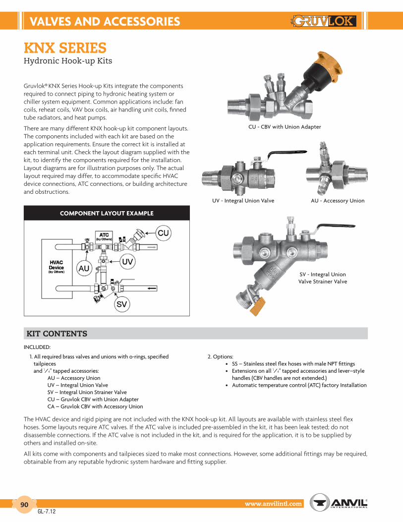
VALVES And AccESSorIES
www.anvilintl.com90
knx seriesHydronic Hook-up Kits
Gruvlok® KNX Series Hook-up Kits integrate the components required to connect piping to hydronic heating system or chiller system equipment. Common applications include: fan coils, reheat coils, VAV box coils, air handling unit coils, finned tube radiators, and heat pumps.
There are many different KNX hook-up kit component layouts.The components included with each kit are based on the application requirements. Ensure the correct kit is installed at each terminal unit. Check the layout diagram supplied with the kit, to identify the components required for the installation. Layout diagrams are for illustration purposes only. The actual layout required may differ, to accommodate specific HVAC device connections, ATC connections, or building architecture and obstructions.
kit contents
CU - CBV with Union Adapter
AU - Accessory UnionUV - Integral Union Valve
SV - Integral Union Valve Strainer Valve
coMPonEnt LAYout EXAMPLE
INCLUDED:
1. All required brass valves and unions with o-rings, specified tailpieces and 1/4" tapped accessories: AU – Accessory Union UV – Integral Union Valve SV – Integral Union Strainer Valve CU – Gruvlok CBV with Union Adapter CA – Gruvlok CBV with Accessory Union
2. Options: • SS – Stainless steel flex hoses with male NPT fittings
• Extensions on all 1/4" tapped accessories and lever–style handles (CBV handles are not extended.) • Automatic temperature control (ATC) factory Installation
The HVAC device and rigid piping are not included with the KNX hook-up kit. All layouts are available with stainless steel flex hoses. Some layouts require ATC valves. If the ATC valve is included pre-assembled in the kit, it has been leak tested; do not disassemble connections. If the ATC valve is not included in the kit, and is required for the application, it is to be supplied by others and installed on-site.
All kits come with components and tailpieces sized to make most connections. However, some additional fittings may be required, obtainable from any reputable hydronic system hardware and fitting supplier.
GL-7.12

VALVES & AccESSorIES
Intro
duct
ion
Coup
lings
Outle
tsFi
tting
sVa
lves
&
Acce
ssor
ies
High
Pres
sure
DI-L
OK®
Nipp
les
Plai
n-En
dFi
tting
sHD
PECo
uplin
gsSo
ck-It
®
Fitti
ngs
Stai
nles
sSt
eel M
etho
dRo
ll Gr
oove
rsIn
stal
latio
n&
Ass
embl
ySp
ecia
lCo
atin
gsDe
sign
Serv
ices
Tech
nica
lDa
taM
aste
r For
mat
3 Pa
rt Sp
ecs.
Pict
oria
lIn
dex
CTS
Copp
er
Syst
em
www.anvilintl.com 91
knx seriesHydronic Hook-up Kits
components
The following components are used in KNX hydronic hook-up kits. The layout illustration supplied with the kit indicates the components used for that particular installation. (Flex hoses are not shown on the images. If supplied, these are installed in place of rigid connections between the components and the HVAC device.)
au – Accessory UnionThe AU accessory union combines an o-ring style union with two tapped ports for accessory connection. Tapped ports are located 90° apart. By default, tapped ports are fitted with a PT Port and Manual Air Vent. Ensure the air vent is mounted vertically. Otherwise, where no accessory is required, the corresponding port is plugged.
uv – Union ValveThe UV integral ball valve union combines a full port ball valve, o-ring styleunion, and multiple tapped ports for accessory connection. By default, onetapped port is fitted with a PT Port. Otherwise, where no accessory isspecified, the corresponding port is plugged.
sv – Strainer ValveThe SV integral ball valve strainer combines a full port ball valve, o-ring style union, wye-pattern strainer, a bypass port, and multiple tapped ports for accessory connection. By default, one tapped port is fitted with a PT Port and another with a hose end drain valve. Otherwise, where no accessory or bypass is specified, the corresponding port is plugged.
cu and ca cbv – Circuit Balancing ValvesThe CU and CA models combine an Gruvlok® CBV with an o-ring style union. The Gruvlok CBV is a multi-turn, wye-pattern, globe-style valve that is equipped with an integral modified venturi and two PT ports. These units enable precise pressure drop measurement, fixed Cv flow correlation, and flow adjustment. The CA model includes two 1/4" NPT tapped ports, located 90° apart, for accessory connection. Tapped ports that are not used are fitted with a brass plug.
Refer to the Installation and Operating Instructions supplied with the Gruvlok Five Turn CBV Venturi Circuit Balancing Valve.
CU - CBV with Union Adapter CA - CBV with Accessory Union
SS Stainless Steel Flex HosesSS flex hoses enable fast and reliable hook-up to hydronic system coils and heat pumps. Installation speed is increased by avoiding the need for precise rigid run-out pipe length measurement and termination. System reliability is improved by reducing connection fatigue due to rigid pipe expansion and contraction. Hose connections are made on-site with customer supplied sealant and adapters, as required.
TailpiecesTailpieces are joined to the corresponding KNX component with a union nut. The union o-ring is compressed in the component o-ring groove to produce a liquid-tight seal when the union nut is tightened.
The tailpiece connection may be the same size as the valve body or reduced by one or more sizes.
GL-7.12

VALVES And AccESSorIES
www.anvilintl.com92
knx seriesHydronic Hook-up Kits
KNX Layout DefaultsUse this table to determine which KNX Layout most closely resembles your application requirements
linear radiator
wild coil
2-way atc
3-way atc, bypass n.o.
3-way atc, bypass n.c.
HD
UV UV
KNX - 1 Layout
HDUVCU
KNX - 2 Layout
UV 2A/2C AU HD CU
KNX - 3 Layout
KNX - 5 Layout KNX - 6 LayoutUV
HDUV
KNX - 4 Layout
UV
CA
HD
CA
HD SV
KNX - 8 Layout KNX - 9 LayoutKNX - 7 Layout
CU2A/2CAUHD
SV
CUAUHD
2A/2C
SV
2A/2C
CAHD
AU SV
KNX - 11 Layout KNX - 12 LayoutKNX - 10 Layout
AU NC
HD
2A/2CNO
AO
SV
CCU
HD
AU NCNO
C
2A/2C
VO SV
CUNO
CNC
2A/2CAU
HD
CU
CO
SV
KNX - 14 Layout KNX - 15 LayoutKNX - 13 Layout
HD
AU
AC
NC
2A/2C NO
CCU
SV
HD
AU
VC
NC
3A/3C NO
CCU
SV
HDAU
CC
NC
3A/3C NO
CCU
SV
GL-7.12

VALVES & AccESSorIES
Intro
duct
ion
Coup
lings
Outle
tsFi
tting
sVa
lves
&
Acce
ssor
ies
High
Pres
sure
DI-L
OK®
Nipp
les
Plai
n-En
dFi
tting
sHD
PECo
uplin
gsSo
ck-It
®
Fitti
ngs
Stai
nles
sSt
eel M
etho
dRo
ll Gr
oove
rsIn
stal
latio
n&
Ass
embl
ySp
ecia
lCo
atin
gsDe
sign
Serv
ices
Tech
nica
lDa
taM
aste
r For
mat
3 Pa
rt Sp
ecs.
Pict
oria
lIn
dex
CTS
Copp
er
Syst
em
www.anvilintl.com 93
knx series - cu (cbv union), ca (cbv accessory)HVAC Hook-up Kits
CU - CBV with Union Adapter
Gruvlok® KNX Series Hook-up Kits integrate the components required to connect piping to hydronic heating system or chiller system equipment. These kits are available in 1/2" to 2" device sizes and are configured to the system designer’s specifications. Each kit is tested, bagged, tagged and delivered to the building site ready for installation.
The CU and CA models combine a Gruvlok CBV with an o-ring style union. The Gruvlok CBV is a multi-turn, wye-pattern, globe-style valve that is equipped with an integral modified venturi and two PT ports. These units enable precise pressure drop measurement, fixed Cv flow correlation and flow adjustment. The CA model also includes two 1/4" NPT tapped ports, located 90° apart, for accessory connection. Tapped ports that are not used are fitted with a brass plug.
technical data material specificationsMAX. WORKING PRESSURE: 300 psi (20 bar)MIN. WORKING PRESSURE: -5 psi (-0.35 bar)MAX. FLUID TEMPERATURE: 300˚F (150˚C) Non-BoilingMIN. FLUID TEMPERATURE: -4˚F (-20˚C) Non-FreezingFLOW DIRECTION: per Flow Direction Arrow
BODY: BrassSTEM & DISC: BrassELASTOMERS: EPDMHANDLE: Reinforced Nylon; ABS
model cu
model ca
GruVLoK KnX cA and cu (ordErInG InForMAtIon)
Sample Part Number ––> CA2-S-T2M1-MV-PO-0-SF-R
(Default)
CA 2- S- T2M1- MV- PO- 0- SF- RGruvlok KNX Body Size Body Type Tailpiece Option 1 Option 2 Extensions Flow Range Application Orientation
CA 1 F TXXX AV AV 0 (default) LF R (default)CU 2 (default) S (default) MV (default) MV 1 SF (default)
3 PT PT4 DV DV5 PO PO (default)6 00 (CU) 00 (CU)
KnX SErIES cu & cA dIMEnSIonS
Model SizeA
B Weight21⁄2 3
In./mm In./mm In./mm In./mm Lbs./Kg
CU11⁄2 3.9 4.9 4.6 1.715 99 124 117 0.77
CU23⁄4 4.1 5.5 4.9 2.020 104 140 124 0.91
CU3 1 4.8 6.3 5.3 3.025 122 160 135 1.36
CU4 11⁄4 5.4 7.0 5.6 3.832 137 178 142 1.72
CU5 11⁄2 6.7 8.5 5.9 5.040 170 216 150 2.27
CU6 2 7.7 9.8 6.7 8.050 196 249 170 3.63
CA11⁄2 5.5 6.5 4.6 2.015 140 165 117 0.91
CA23⁄4 5.6 7.0 4.9 2.420 142 178 124 1.09
CA3 1 6.2 7.7 5.3 3.525 157 196 135 1.59
CA4 11⁄4 7.0 8.7 5.6 4.532 178 221 142 2.04
CA5 11⁄2 7.7 9.5 5.9 6.540 196 241 150 2.95
CA6 2 8.9 11.0 6.7 11.050 226 279 170 4.99
Option 2
See Configuration Options on page 98.
GL-7.12

VALVES And AccESSorIES
www.anvilintl.com94
knx series - circuit balancinG valvesHVAC Hook-up Kits
300
250
200
150
100
50
Pre
ssur
e -
psi
0-18
5010
10038
15066
20093
250121
300 (˚F)149 (˚C)
Temperature
3.4
6.9
10.3
13.8
17.2
20.7
Pre
ssur
e -
bar
dEZIncIFIcAtIon rESIStAntNOTE: These instructions pertain only to Dezincification Resistant models having red and blue PT Port cap retainers. For other models, please see our website.
typical applications
Gruvlok® circuit balancing valves are used to regulate the flow of hydronic fluid in heating and chiller system piping circuits. When the minimum design flow requirement of each circuit is met, with the system operating at maximum design flow, the system is considered, "balanced". Suitable liquids include
water, and up to 50/50 water/glycol mixtures (both ethylene and propylene glycol).adjustment. The CA model also includes two 1/4" NPT tapped ports, located 90° apart, for accessory connection. Tapped ports that are not used are fitted with a brass plug.
maximum operatinG parameters technical dataCONNECTION: Model CBV-VS Solder Joint, Model CBV-VT Threaded Joint, Model CBV-VB Threaded BSPPMAX. WORKING PRESSURE: 300 psi/20 bar (PN20)OPERATING TEMPERATURE RANGE: -4˚F to 300˚F (-20˚C to 150˚C)
material specificationsBODY, BONNET, STEM AND DISK: Brass alloy CW602N Dezincification Resistant (DZR) to EN12165 per ISO-6509ELASTOMERS: EPDMHANDWHEEL: Reinforced Nylon; ABS
FLoW rAtE rAnGES
Valve Size Minimum Flowrate
Maximum Flowrate
FlowrateCoefficients
Model In./mm gpm/lps gpm/lps Cv/Kv
CBV050V(X)CR-LF1⁄2" LF 0.26 1.98 0.69
DN15 LF 0.02 0.12 0.59
CBV075V(X)CR-LF3⁄4" LF 0.41 3.11 1.08
DN20 LF 0.03 0.20 0.93
CBV050V(X)CR1⁄2" 1.22 9.57 3.20
DN15 0.08 0.60 2.74
CBV075V(X)CR3⁄4" 1.99 13.76 5.21
DN20 0.13 0.87 4.47
CBV100V(X)CR1" 4.57 22.97 12.01
DN25 0.29 1.45 10.29
CBV125V(X)CR11⁄4" 4.98 41.02 13.07DN32 0.31 2.58 11.20
CBV150V(X)CR11⁄2" 9.02 50.07 23.69DN40 0.57 3.15 20.30
CBV200V(X)CR2" 15.05 81.92 40.70
DN50 0.98 5.16 34.88
note: In model number, (X) = Connection Type. S = Sweat, T = NPT, B = BSPP (ISO-228)
GL-7.12

VALVES & AccESSorIES
Intro
duct
ion
Coup
lings
Outle
tsFi
tting
sVa
lves
&
Acce
ssor
ies
High
Pres
sure
DI-L
OK®
Nipp
les
Plai
n-En
dFi
tting
sHD
PECo
uplin
gsSo
ck-It
®
Fitti
ngs
Stai
nles
sSt
eel M
etho
dRo
ll Gr
oove
rsIn
stal
latio
n&
Ass
embl
ySp
ecia
lCo
atin
gsDe
sign
Serv
ices
Tech
nica
lDa
taM
aste
r For
mat
3 Pa
rt Sp
ecs.
Pict
oria
lIn
dex
CTS
Copp
er
Syst
em
www.anvilintl.com 95
knx series - au (accessory union)HVAC Hook-up Kits
Gruvlok® KNX Series Hook-up Kits integrate the components required to connect piping to hydronic heating system or chiller system equipment. These kits are available in 1/2" to 2" device sizes and are configured to the system designer’s specifications. Each kit is tested, bagged, tagged and delivered to the building site ready for installation.
The AU accessory union combines an o-ring style union with two tapped ports for accessory connection. Tapped ports are located 90° apart on a rotational axis. By default, tapped ports are fitted with a PT Port and Manual Air Vent. Otherwise, where no accessory is required, the corresponding port is plugged.
technical data material specificationsMAX. WORKING PRESSURE: 600 psi (41 bar)MIN. WORKING PRESSURE: -5 psi (-0.35 bar)MAX. FLUID TEMPERATURE: 300˚F (150˚C) Non-BoilingMIN. FLUID TEMPERATURE: -4˚F (-20˚C) Non-FreezingFLOW DIRECTION: Bi-directional
BODY: BrassELASTOMERS: EPDM
GruVLoK KnX Au (ordErInG InForMAtIon)
Sample Part Number ––> AU2-S-T2M1-MV-PT-0-S
(Default)
AU 2- S- T2M1- MV- PT- 0- SGruvlok KNX Body Size Body Type Tailpiece Option 1 Option 2 Extensions Application Orientation
AU 1 M TXXX AV AV 0 (default) S (default)2 (default) F MV (default) MV 1 R3 S (default) PT PT (default)4 DV DV5 PO PO6
KnX SErIES Au dIMEnSIonS
Model SizeA
B WeightMPT FPT Sweat
In./mm In./mm In./mm In./mm In./mm Lbs./Kg
AU11⁄2 2.1 2.0 2.1 1.4 1.015 53 51 53 36 0.45
AU23⁄4 2.5 2.1 2.2 1.8 1.220 64 53 56 46 0.54
AU31 2.6 2.2 2.4 1.9 1.625 66 56 61 48 0.73
AU411⁄4 3.0 2.3 3.0 2.5 2.232 76 58 76 64 1.00
AU511⁄2 3.1 2.6 3.0 3.0 3.040 79 66 76 76 1.36
AU62 3.4 2.8 3.0 3.8 4.550 86 71 76 97 2.04
Both option ports are 1/4" NPT tapped. If an air vent is specified, it is installed in the Option 1 position. If a PT Port is specified, it is installed in the Option 2 position.
See Configuration Options on page 98.
GL-7.12

VALVES And AccESSorIES
www.anvilintl.com96
knx series - uv (inteGral ball valve union)HVAC Hook-up Kits
Gruvlok® KNX Series Hook-up Kits integrate the components required to connect piping to hydronic heating system or chiller system equipment. These kits are available in 1/2" to 2" device sizes and are configured to the system designer’s specifications. Each kit is tested, bagged, tagged and delivered to the building site ready for installation.
The UV integral ball valve union combines a full port ball valve, o-ring style union and multiple tapped ports for accessory connection. By default, one tapped port is fitted with a PT Port. Otherwise, where no accessory is specified, the corresponding port is plugged.
technical data material specificationsMAX. WORKING PRESSURE: 600 psi (41 bar)MIN. WORKING PRESSURE: -5 psi (-0.35 bar)MAX. FLUID TEMPERATURE: 300˚F (150˚C) Non-BoilingMIN. FLUID TEMPERATURE: -4˚F (-20˚C) Non-FreezingFLOW DIRECTION: Bi-directional
BODY: BrassBALL VALVE: Chrome Plated Brass, Full PortVALVE SEAT: PTFEELASTOMERS: EPDMHANDLE: Chrome Plated Steel, Plastisol Coated
GruVLoK KnX uV (ordErInG InForMAtIon)
Sample Part Number ––> UV2-S-T2S2-PT-PO-PO-0-S
(Default)
UV 2- S- T2S2- PT- PO- PO- 0- SGruvlok KNX Body Size Body Type Tailpiece Option 1 Option 2 Option 3 Extensions Application Orientation
UV 1 F TXXX AV AV AV 0 (default) S (default)2 (default) S (default) MV MV MV 1 R3 PT (default) PT PT4 DV DV DV5 PO PO (default) PO (default)6
KnX SErIES uV dIMEnSIonS
Model SizeA
B WeightFPT Sweat
In./mm In./mm In./mm In./mm Lbs./Kg
UV11⁄2 2.9 3.2 1.7 1.615 74 81 43 1.73
UV23⁄4 3.3 3.7 2.2 1.920 84 94 56 0.86
UV31 3.6 4.1 2.2 3.025 91 104 56 1.36
UV411⁄4 4.6 5.2 2.9 3.932 117 132 74 1.77
UV511⁄2 5.1 5.8 3.5 5.340 130 147 89 2.40
UV62 6.0 6.8 4.0 7.750 152 173 102 3.49
All option ports are ¼" NPT tapped. If an air vent is specified, it is installed in the Option 1 position. If a drain valve is specified, it is installed in the Option 2 position.
See Configuration Options on page 98.
GL-7.12

VALVES & AccESSorIES
Intro
duct
ion
Coup
lings
Outle
tsFi
tting
sVa
lves
&
Acce
ssor
ies
High
Pres
sure
DI-L
OK®
Nipp
les
Plai
n-En
dFi
tting
sHD
PECo
uplin
gsSo
ck-It
®
Fitti
ngs
Stai
nles
sSt
eel M
etho
dRo
ll Gr
oove
rsIn
stal
latio
n&
Ass
embl
ySp
ecia
lCo
atin
gsDe
sign
Serv
ices
Tech
nica
lDa
taM
aste
r For
mat
3 Pa
rt Sp
ecs.
Pict
oria
lIn
dex
CTS
Copp
er
Syst
em
www.anvilintl.com 97
knx series - sv (inteGral ball valve strainer)HVAC Hook-up Kits
Gruvlok® KNX Series Hook-up Kits integrate the components required to connect piping to hydronic heating system or chiller system equipment. These kits are available in 1/2" to 2" device sizes and are configured to the system designer’s specifications. Each kit is tested, bagged, tagged and delivered to the building site ready for installation.
The SV integral ball valve strainer combines a full port ball valve, o-ring style union, wye-pattern strainer and multiple tapped ports for accessory connection. By default, one tapped port is fitted with a PT Port and another with a hose end drain valve. Otherwise, where no accessory or bypass is specified, the corresponding port is plugged.
technical data material specificationsMAX. WORKING PRESSURE: 600 psi (41 bar)MIN. WORKING PRESSURE: -5 psi (-0.35 bar)MAX. FLUID TEMPERATURE: 300˚F (150˚C) Non-BoilingMIN. FLUID TEMPERATURE: -4˚F (-20˚C) Non-FreezingFLOW DIRECTION: Body to Union Connection
BODY: BrassSTRAINER: 20 Mesh Stainless SteelBALL VALVE: Chrome Plated Brass, Full PortVALVE SEAT: PTFEELASTOMERS: EPDMHANDLE: Chrome Plated Steel, Plastisol Coated
GruVLoK KnX SV (ordErInG InForMAtIon)
Sample Part Number ––>SV2-S-T2S2-PT-DV-PO-P0- P1-0-S
(Default)
SV 2- S- T2S2- PT- DV- PO- PO- P1- 0- SGruvlok
KNXBodySize
BodyType Tailpiece Option 1 Option 2 Option 3 Option 4 Bypass Extensions Application
OrientationSV 1 F TXXX AV DV (default) PT PT 00 0 (default) S (default)
2 (default) S (default) MV PO PO (default) PO (default) P1 (default) 13 PT (default) P24 PO56
KnX SErIES SV dIMEnSIonS
Model SizeA
BC Bypass
Port WeightFPT Sweat
In./mm In./mm In./mm In./mm In. Lbs./Kg
SV11⁄2 5.0 5.2 5.5
0.50 FPT1.6
15 127 132 140 1.73
SV23⁄4 5.2 5.6 5.8
0.50 FPT1.9
20 132 142 147 0.86
SV31 6.7 7.3 6.9
0.50 FPT3.0
25 170 185 175 1.36
SV411⁄4 7.1 7.7 7.3
0.75 FPT3.9
32 180 196 185 1.77
SV511⁄2 8.7 9.4 8.4
0.75 FPT5.3
40 221 239 213 2.40
SV62 9.4 10.3 8.8
1.00 FPT7.7
50 239 262 224 3.49
All option ports are 1/4" NPT tapped. See Dimensions and Weights for the bypass portsize. If an air vent is specified, it is installed in the Option 1 position. If a drain valve isspecified, it is installed in the Option 2 position.
See Configuration Options on page 98.
GL-7.12

VALVES And AccESSorIES
www.anvilintl.com98
knx series - confiGuration optionsHVAC Hook-up Kits
BodY SIZESize Description
In./mm
11⁄213
23⁄4 (default)
19
3125
411⁄432
511⁄238
6250
BodY tYPEType Description
F Female NPTS Sweat (default)
oPtIon / BYPASSType Description
In.
AV Automatic Air VentMV Manual Air VentPT PT Port (default)DV Drain Valve with Hose End and Retained CapP0 1⁄4" Brass Plug (default)P1 1⁄2" Brass PlugP2 3⁄4" Brass Plug
EXtEnSIonSType Description
In.
0 No Extensions (default)
1 Handle / Options extended 13⁄4" foraccess through Insulation APPLIcAtIon orIEntAtIon
Type Description
R Body connects to ReturnS Body connects to Supply (default)00 Not Applicable
tAILPIEcE
Model A (Body) B C (MPT) Model A (Body) B C (Sweat) Model A (Body) B C (FPT)number In. In. In. number In. In. In. number In. In. In.
T1M1 1⁄2 1.563 1⁄2 T1S0 1⁄2 0.430 3⁄8 T1F1 1⁄2 0.650 1⁄2
T2M1 3⁄4 1.563 1⁄2 T1S1 1⁄2 0.650 1⁄2 T2F1 3⁄4 1.110 1⁄2
T2M2 3⁄4 1.760 3⁄4 T1S2 1⁄2 0.800 3⁄4 T2F2 3⁄4 0.800 3⁄4
T3M1 1 2.000 1⁄2 T2S0 3⁄4 0.452 3⁄8 T3F1 1 1.800 1⁄2
T3M2 1 2.000 3⁄4 T2S1 3⁄4 0.750 1⁄2 T3F2 1 1.250 3⁄4
T3M3 1 2.000 1 T2S2 3⁄4 0.790 3⁄4 T3F3 1 0.900 1
T4M1 11⁄4 1.775 1⁄2 T3S1 1 0.940 1⁄2 T4F2 11⁄4 1.800 3⁄4
T4M2 11⁄4 2.000 3⁄4 T3S2 1 0.850 3⁄4 T4F3 11⁄4 1.990 1
T4M3 11⁄4 2.000 1 T3S3 1 1.005 1 T4F4 11⁄4 1.000 11⁄4
T4M4 11⁄4 2.000 11⁄4 T4S2 11⁄4 1.170 3⁄4 T5F3 11⁄2 2.500 1
T5M2 11⁄2 1.890 3⁄4 T4S3 11⁄4 1.330 1 T5F4 11⁄2 2.500 11⁄4
T5M3 11⁄2 2.500 1 T4S4 11⁄4 1.100 11⁄4 T5F5 11⁄2 1.250 11⁄2
T5M4 11⁄2 2.500 11⁄4 T5S3 11⁄2 1.380 1 T6F4 2 3.000 11⁄4
T5M5 11⁄2 2.500 11⁄2 T5S4 11⁄2 1.460 11⁄4 T6F5 2 3.000 11⁄2
T6M3 2 2.047 1 T5S5 11⁄2 1.225 11⁄2 T6F6 2 1.160 2
T6M4 2 3.000 11⁄4 T6S4 2 1.520 11⁄4
T6M5 2 3.000 11⁄2 T6S5 2 1.620 11⁄2
T6M6 2 3.000 2 T6S6 2 1.446 2
GL-7.12

VALVES & AccESSorIES
Intro
duct
ion
Coup
lings
Outle
tsFi
tting
sVa
lves
&
Acce
ssor
ies
High
Pres
sure
DI-L
OK®
Nipp
les
Plai
n-En
dFi
tting
sHD
PECo
uplin
gsSo
ck-It
®
Fitti
ngs
Stai
nles
sSt
eel M
etho
dRo
ll Gr
oove
rsIn
stal
latio
n&
Ass
embl
ySp
ecia
lCo
atin
gsDe
sign
Serv
ices
Tech
nica
lDa
taM
aste
r For
mat
3 Pa
rt Sp
ecs.
Pict
oria
lIn
dex
CTS
Copp
er
Syst
em
www.anvilintl.com 99
ftv-s (straight) & ftv-a (angle body)Tri-Service Valve
SErVIcE rEcoMMEndAtIonS:The Model FTV-S & FTV-A Tri-Service Valve is primarily designed for installation in pump discharge piping where it functions as a spring loaded silent check valve, flow control valve and shut off valve.
oPErAtIon:The Model FTV Tri-Service Valve operates automatically and silently. Line pressure of approximately 1⁄4 PSI will open the disc. The spring closes the disc as the line flow approaches zero in order to prevent flow reversal & water hammer. The flow through the valve can be adjusted from bubble tight shut off to full flow by the threaded rising stem.
FEAturES:The unique convertible body design permits the valve to be changed on site from the straight to the angle configuration.
Flow measurement (where an approximate indication is acceptable) is obtained by flow measuring ports on each side of the valve seat. Pressure differential is easily recorded using differential pressure measurement devices. If precision accuracy is required, we recommend that a Gruvlok® Circuit Balancing Valve be installed downstream from the FTV valve.
features & benefits
• Three functions, one valve — 1. Spring-closure design, 2. Non-slam check valve, 3. Flow throttling valve
• Reduced field installation and material cost
• Stainless steel spring
• High-strength resin seat EPDM for 8" and larger
• Anti-rotation lugs on the inlet and outlet. These lugs, combined with the Gruvlok 7401 Rigidlok Coupling or the Gruvlok flange adapter provides for a ridged rotation free installation
• Flow measurement and pump throttling capabilities
• Temperature measurement capability
• Spring-closure design check valve prevents gravity or reverse circulation when pump is not operating
• Bonnet “O” Ring can be replaced under full system pressure by back seating of valve stem
• Suitable for maximum working pressure to 375 psi (26 bar) and temperatures to 230°F. (110°C).
• Valve seat can be changed in the field without use of special tools
• Low pressure drop due to “Y” pattern valve design
• Valve Cv designed to ASHRAE flow recommendations for quiet system operation
• Drip-tight shut off valve smoke development rating of 50 or less
See pages 175-178 for installation instructions and flow data.
GL-7.12

VALVES And AccESSorIES
www.anvilintl.com100
ModEL FtV-A (AnGLE)
Connection Size A
B (fully open)
C D E F
Flange 125/150
PSI G
Flange 250/300
PSI G
Approx. Wt.
Each
In./mm In./mm In./mm In./mm In./mm In./mm In./mm In./mm In./mm Lbs./Kg
21/2 73/8 7 23/4 45/8 1 29/16 7 71/2 1965 187 178 70 117 25 65 178 191 9
3 83/16 713/16 27/16 37/8 1 3 71/2 81/4 2480 208 198 62 98 25 80 191 210 11
4 95/8 8 3 43/8 11/4 37/16 91/4 10 42100 244 203 80 111 32 87 235 254 19
5 12 101/8 35/8 51/2 11/4 415/16 10 11 81125 305 257 92 140 32 125 254 279 37
6 141/8 103/8 47/16 65/8 2 57/8 11 121/2 120150 359 264 113 168 51 149 279 318 54
8 1815/16 183/4 511/16 93/16 21/4 77/8 131/2 15 300200 481 476 144 233 57 200 343 381 136
10 205/16 24 69/16 93/4 21/4 915/32 16 171/2 450250 516 610 167 248 57 241 409 445 204
12 241/16 261/4 75/8 14 21/4 125/8 19 201/2 860300 611 667 194 356 57 321 483 521 390
ModEL FtV-S (StrAIGHt)
Connection Size
AB
(fully open)
C E F
Flange 125/150
PSI G
Flange 250/300
PSI G
Approx. Wt.
Each
In./mm In./mm In./mm In./mm In./mm In./mm In./mm In./mm Lbs./Kg
21/2 12 7 23/4 1 29/16 7 71/2 1965 305 178 70 25 65 178 191 9
3 12 713/16 27/16 1 3 71/2 81/4 2480 305 198 62 25 80 191 210 11
4 14 8 3 11/4 37/16 91/4 10 42100 356 203 80 32 87 235 254 19
5 171/2 101/8 35/8 11/4 415/16 10 11 81125 445 257 92 32 125 254 279 37
6 2011/16 103/8 47/16 2 57/8 11 121/2 120150 525 264 113 51 149 279 318 54
8 283/16 2213/16 511/16 21/4 77/8 131/2 15 300200 716 579 144 57 200 343 381 136
10 30 285/8 69/16 21/4 915/32 16 171/2 450250 762 727 167 57 241 409 445 204
12 381/16 325/8 75/8 21/4 125/8 19 201/2 850300 967 829 194 57 321 483 521 390
ftv-s (straight) & ftv-a (angle body)Tri-Service Valve
See Page 51 for O.D. SizeSee Page 51 for O.D. Size
material specifications
BODY: Ductile Iron ASTM A 536 Grade 65-45-12
DISC: Bronze ASTM B 584 C-84400
STEM: Stainless Steel ASTM A 582 Type 416
SEAT: High Strength Engineered Resin
SPRING: Stainless Steel ASTM A 302
“O” RINGS: BUNA
COUPLINGS/FLANGES: Ductile Iron ASTM A 536 Grade 65-45-12 with EPDM2 Gaskets (Optional)
INSULATION: Optional1
NOTE 1: Optional pre-formed insulation is available to meet ASTM D 1784 Class 14253-C, MEA #7-87, ASTM E 136 with a flame spread rating of 25 or less and a smoke development rating of 50 or less.
NOTE 2: EPDM is not suitable for oil service.
NOTE: For temperatures between 230°F and 300°F (110°C and 149°C) specify Viton Elastomers
B
E (diameter)
C
A
G
F
B D
A
C
E (diameter) F
G
GruvlokAnti-Rotation Lugs
GruvlokAnti-Rotation Lugs
Flow Indicator Scale
Bonnet “O” Ring
Stainless Steel Stem
Stainless Steel Spring
High Strength Resin SealEDPM for 8" and larger
Bronze Disc
Flow/TemperatureMeasurement PortsDrain Connections(on opposite side)
GL-6.11

VALVES & AccESSorIES
Intro
duct
ion
Coup
lings
Outle
tsFi
tting
sVa
lves
&
Acce
ssor
ies
High
Pres
sure
DI-L
OK®
Nipp
les
Plai
n-En
dFi
tting
sHD
PECo
uplin
gsSo
ck-It
®
Fitti
ngs
Stai
nles
sSt
eel M
etho
dRo
ll Gr
oove
rsIn
stal
latio
n&
Ass
embl
ySp
ecia
lCo
atin
gsDe
sign
Serv
ices
Tech
nica
lDa
taM
aste
r For
mat
3 Pa
rt Sp
ecs.
Pict
oria
lIn
dex
CTS
Copp
er
Syst
em
www.anvilintl.com 101
fiG. 7260Tee Strainer
The Fig. 7260 Tee Strainer provides an economical, compact and hydraulically efficient means of protecting valuable piping system components. The in-line, twin-fold strainer basket provides more than 100% of the projected pipe area for open flow through the strainer screen which results in excellent flow performance across the strainer.
Gruvlok Strainers are designed and tested to ensure long term, reliable service in working pressures up to 750 psi (51.7 bar), depending on size and the pressure rating of the connecting coupling.
material specificationsBODY:2" - 12" Ductile iron conforming to ASTM A 536, Grade 65-45-12
14" - 18" Carbon steel pipe conforming to ASTM A 53
STRAINER BASKET:Stainless steel type 304 bar and woven wire screen. 12 mesh in sizes 2" - 3" and 6 mesh in sizes 4" - 18". Other mesh sizes available on request.
ACCESS COUPLING & END CAP:
2" - 12" Ductile iron conforming to ASTM A 536, Grade 65-45-12
14" - 18" Low carbon steel conforming to ASTM A 53
BOLTS & NUTS:Heat treated, oval-neck track head bolts conforming to ASTM A 183 Grade 2 with a minimum tensile strength of 110,000 psi and heavy hex nuts of carbon steel conforming to ASTM A 563. Bolts and nuts are provided zinc electroplated as standard.
COUPLING GASKETS:Elastomer properties as designated by ASTM D 2000 Grade “E” EPDM -40°F to +230°F (service temp. range)Grade “EP” EPDM -40°F to +250°F (service temp. range)Other options available upon request.
DRAIN PLUG: Carbon steel square head plug conforming to ASME B16.11
TAP SIzES: 2"-4" – 1⁄2 NPT, 5"-8" – 3⁄4 NPT, 10"-18" – 1 NPT,
COATING:2" - 12" - Rust-inhibiting paint — color: orange (standard)Hot Dip Galvanized conforming to ASTM A 153 (optional)Other Colors Available (IE: RAL3000 and RAL9000)For other Coating requirements contact an Anvil Representative.
NOTE: Most U.S. piping engineers specify system startup instructions for new systems which include removing and cleaning the strainer screen after system flushing of main piping before the system is put into normal operation. After flushing, replace the strainer screen. Flow data values are based on flow of clean water at ambient temperatures. The pressure drop across a strainer, 50% clogged, is approximately twice as great as that of a clean strainer. Strainer baskets need a routine maintenance program to maintain efficiency and to prevent excess pressure drop caused by a clogged screen.
FLOW (GPM)
FLOW CHARACTERISTICS
ISP - PO
RD E
RUSSE
RP
GL-7.12
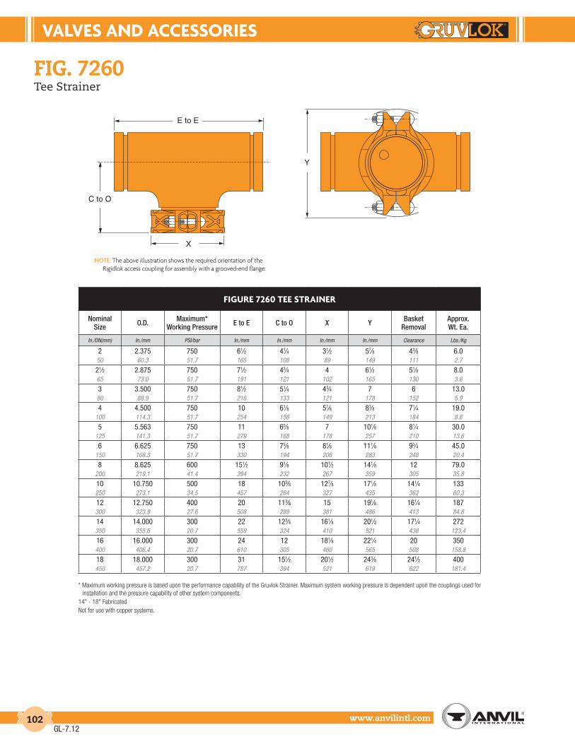
VALVES And AccESSorIES
www.anvilintl.com102
X
E to E
C to O
Y
fiG. 7260Tee Strainer
NOTE: The above illustration shows the required orientation of the Rigidlok access coupling for assembly with a grooved-end flange.
* Maximum working pressure is based upon the performance capability of the Gruvlok Strainer. Maximum system working pressure is dependent upon the couplings used for installation and the pressure capability of other system components.
14" - 18" FabricatedNot for use with copper systems.
FIGurE 7260 tEE StrAInEr
Nominal Size O.D. Maximum*
Working Pressure E to E C to O X Y Basket Removal
Approx. Wt. Ea.
In./DN(mm) In./mm PSI/bar In./mm In./mm In./mm In./mm Clearance Lbs./Kg
2 2.375 750 61⁄2 41⁄4 31⁄2 57⁄8 43⁄8 6.050 60.3 51.7 165 108 89 149 111 2.7
21⁄2 2.875 750 71⁄2 43⁄4 4 61⁄2 51⁄8 8.065 73.0 51.7 191 121 102 165 130 3.6
3 3.500 750 81⁄2 51⁄4 43⁄4 7 6 13.080 88.9 51.7 216 133 121 178 152 5.9
4 4.500 750 10 61⁄8 57⁄8 83⁄8 71⁄4 19.0100 114.3 51.7 254 156 149 213 184 8.6
5 5.563 750 11 65⁄8 7 101⁄8 81⁄4 30.0125 141.3 51.7 279 168 178 257 210 13.6
6 6.625 750 13 75⁄8 81⁄8 111⁄8 93⁄4 45.0150 168.3 51.7 330 194 206 283 248 20.4
8 8.625 600 151⁄2 91⁄8 101⁄2 141⁄8 12 79.0200 219.1 41.4 394 232 267 359 305 35.8
10 10.750 500 18 103⁄8 127⁄8 171⁄8 141⁄4 133250 273.1 34.5 457 264 327 435 362 60.3
12 12.750 400 20 113⁄8 15 191⁄8 161⁄4 187300 323.9 27.6 508 289 381 486 413 84.8
14 14.000 300 22 123⁄4 161⁄8 201⁄2 171⁄4 272350 355.6 20.7 559 324 410 521 438 123.4
16 16.000 300 24 12 181⁄8 221⁄4 20 350400 406.4 20.7 610 305 460 565 508 158.8
18 18.000 300 31 151⁄2 201⁄2 243⁄8 241⁄2 400450 457.2 20.7 787 394 521 619 622 181.4
GL-7.12

VALVES & AccESSorIES
Intro
duct
ion
Coup
lings
Outle
tsFi
tting
sVa
lves
&
Acce
ssor
ies
High
Pres
sure
DI-L
OK®
Nipp
les
Plai
n-En
dFi
tting
sHD
PECo
uplin
gsSo
ck-It
®
Fitti
ngs
Stai
nles
sSt
eel M
etho
dRo
ll Gr
oove
rsIn
stal
latio
n&
Ass
embl
ySp
ecia
lCo
atin
gsDe
sign
Serv
ices
Tech
nica
lDa
taM
aste
r For
mat
3 Pa
rt Sp
ecs.
Pict
oria
lIn
dex
CTS
Copp
er
Syst
em
www.anvilintl.com 103
FIGurE 758 G GrooVEd-End “WYE” StrAInEr
Nominal Size O.D.
Dimensions Approx. Wt. EachA B C
Plug Size D
In./DN(mm) In./mm In./mm In./mm In./mm In./mm Lbs./Kg
2 2.375 77⁄8 51⁄4 1⁄2 7 12.050 60.3 200 133 25 178 5.4
21⁄2 2.875 10 61⁄2 1 93⁄4 18.065 73.0 254 165 25 248 8.2
3 3.500 101⁄8 7 1 10 23.080 88.9 257 178 25 254 10.4
4 4.500 121⁄8 81⁄4 11⁄2 12 42.0100 114.3 308 210 38 305 19.1
5 5.563 155⁄8 111⁄4 2 17 80.0125 141.3 396 286 51 432 36.3
6 6.625 181⁄2 131⁄2 2 20 112.0150 168.3 470 343 51 508 50.8
8 8.625 215⁄8 151⁄2 2 223⁄4 205.0200 219.1 549 394 51 577 93.0
10 10.750 253⁄4 181⁄2 2 28 277.0250 273.1 654 470 51 711 125.6
12 12.750 30 213⁄4 2 30 470.0300 323.9 762 552 51 762 213.2
model 758GGrooved-End “Wye” Strainer
SErVIcE rEcoMMEndAtIonSFor use in water, oil and gas piping to provide economical protection for pumps, meters, valves, compressors, traps and similar equipment.
ScrEEnSStandard screens for Y-Strainer are perforated 304 Stainless Steel with spot welded seam. Mesh lining is available in all alloys for extra fine straining. Recommended standard perforations are listed below in the material specifications.
GruVLoK StrAInEr BASKEtFurnished as standard in sizes 8" (43 mm) and larger. A one-quarter turn securely locks the screen in its seat and frees the serviceman for securing the cover flange to the body of the strainer.Contact an Anvil Representative for other applications.
conStructIonAll covers have an NPT blowoff outlet at location “C”. A recessed seat in the cover ensures accurate screen alignment. Bosses at the inlet and outlet flanges are provided for gauge taps.
Self-cleaning is done by opening the valve or plug connected to the blowoff outlet. (When ordering, advise when strainers are to be mounted in vertical piping, the cover can be rotated to position the blowoff at the lowest point.)
BLoWoFF outLEtSTapped NPT size specified in the dimension table. Blowoff outlets are not normally furnished with plugs.
INDIVIDUALLY HYDROSTATICALLY TESTED
Working Pressures Non-Shock 640 PSI @ 150°F (45 Bar @ 65°C)
flow data:NOTE 1. Most U.S. piping engineers specify system startup instructions for new systems which
include removing the pre-filter screen after system flushing of the main piping before the system is put into normal operation. Flow data values are based on flow of clean water at ambient temperatures. The pressure drop across the diffuser basket strainer, 50% clogged, is approximately twice as great as that of a clean strainer.
NOTE 2. Suction Diffuser baskets need a routine maintanence program to maintain system efficiency.
material specificationsBODY & COVER: Ductile Iron ASTM A 395 Grade 60-40-18
FLAT GASKETS: Non-asbestos
SCREEN: 2" - 4" Type 304 Stainless Steel 1⁄16" (1.6mm) dia. holes 5" - 12" Type 304 Stainless Steel 1⁄8" (3.2mm) dia. holes.
COUPLING: Ductile iron ASTM A 536 Grade 65-45-12
* Maximum working pressure is based upon the performance capability of the Gruvlok® Strainer. Maximum system working pressure is dependant upon the couplings used for installation and the pressure capacity of other system components.
Not for use with copper systems.
.1
2
3
456789
2
3
45678910
2 3 4 5 6 7 8 910
11⁄2 21⁄22 3 4 5 6 8 10 12
Cv
PO
RD
ER
US
SE
RP
.i.s.p -
FLOW RATE - g.p.m.
GROOVED END “Y” TYPE STRAINERSSIZE (inches)
100 2 3 4 5 6 7 8 9 1000 2 3 4 5 6 7
1.0
B
C (NPT)
D Screen
Removal
A
GL-7.12

VALVES And AccESSorIES
www.anvilintl.com104
FIGurE 768 G GrooVEd-End “WYE” StrAInEr
Nominal Size O.D. Working
Pressure
Dimensions Cv Values
Approx. Wt. EachA B C D
Plug Size
In./DN(mm) In./mm PSI/bar In./mm In./mm In./mm In./mm Lbs./Kg
2 2.375 300 93⁄4 71⁄8 49⁄16 1⁄2 59 9.350 60.3 20.7 248 192 116 12 4.2
21⁄2 2.875 300 103⁄4 713⁄16 413⁄16 1⁄2 92 13.265 73.0 20.7 273 211 122 12 6.0
3 3.500 300 113⁄4 811⁄16 51⁄16 1 162 18.080 88.9 20.7 298 231 129 25 8.2
4 4.500 300 141⁄4 105⁄8 65⁄8 1 284 26.4100 114.3 20.7 362 281 168 25 12.0
5 5.563 300 161⁄2 13 103⁄16 1 410 46.4125 141.3 20.7 419 330 258 25 22.0
6 6.625 300 181⁄2 141⁄16 85⁄8 11⁄2 770 70.4150 168.3 20.7 470 357 219 38 32.0
8 8.625 300 24 177⁄8 113⁄16 11⁄2 1010 121.0200 219.1 20.7 610 454 284 38 55.0
10 10.750 300 27 209⁄16 125⁄8 11⁄2 1800 182.6250 273.1 20.7 686 522 320 38 83.0
12 12.750 300 30 24 143⁄8 11⁄2 2800 277.2300 323.9 20.7 762 609 366 38 126.0
14 14.000 300 40 2915⁄16 187⁄8 11⁄2 4600 418.0350 355.6 20.7 1016 760 480 38 190.0
16 16.000 300 42 309⁄16 19 11⁄2 5800 495.0400 406.4 20.7 1067 777 483 38 225.0
material specifications
model 768GGlobally Sourced Grooved-end “Wye” Strainer
The Grooved-end Wye-Strainers are designed to strain debris and foreign matter from piping systems and thus provide inexpensive protection for costly pumps, meters and other components. The Strainer can be installed quickly and easily with two mechanical couplings and the straight flow through design provides for lower pressure drop. This strainer features a stainless steel screen that is secured with an end cap and mechanical coupling. Cleaning and maintenance of the screen can be accomplished easily by removing the coupling. The Strainer is suitable for vertical and horizontal installations.
BODY: Ductile iron ASTM A 536 Grade 65-45-12
END CAP: Ductile iron ASTM A 536 Grade 65-45-12
SCREEN:* 2" - 3" Type 304 Stainless Steel to ASTM A 240 - 1⁄16" (1.6 mm) perforations 4" - 12" Type 304 Stainless Steel to ASTM A 240 - 1⁄8" (3.2 mm) perforations Other perforations are available upon request
COUPLING: Ductile iron ASTM A 536 Grade 65-45-12
GASKET:* EPDM Temperature range -40°F - +230°F (-40° to 110°C) Nitrile Temperature range -20°F to 180°F (-29° to 82°C)
BLOW DOWN PORT: 2" & 21⁄2": 1⁄2" tapped with plug, 3" & 4": 1" tapped with plug, 6" - 12": 11⁄2" tapped with plug
* Custom screens and/or gaskets are available upon request. Strainer baskets need a routine maintenance program to maintain efficiencyand to prevent excess pressure drop caused by a clogged screen.
Not for use in copper systems.• Pressure ratings listed are CWP (cold water pressure) or maximum working pressure within the service temperature
range of the gasket used in the coupling. This rating may occasionally differ from maximum working pressures listed and/or approved by UL, ULC, and/or FM as testing conditions and test pipes differ.
• Maximum working pressure and end loads listed are total of internal and external pressures and loads based on Sch. 40 steel pipe with roll grooves to ANSI C606-97 specifications.
• For one time field test only the maximum joint working pressure may be increased 11⁄2 times the figures shown.• Warning: Piping systems must always be depressurized and drained before attempting disassembly and or removal of
any components.
Values for flow of water at +60°F (+16°C)
Where: Q = Flow (GPM) CV = flow coefficient ∆P = Pressure drop (PSI)
B
DPlug Size
A
CScreen
Removal
GL-7.12

VALVES & AccESSorIES
Intro
duct
ion
Coup
lings
Outle
tsFi
tting
sVa
lves
&
Acce
ssor
ies
High
Pres
sure
DI-L
OK®
Nipp
les
Plai
n-En
dFi
tting
sHD
PECo
uplin
gsSo
ck-It
®
Fitti
ngs
Stai
nles
sSt
eel M
etho
dRo
ll Gr
oove
rsIn
stal
latio
n&
Ass
embl
ySp
ecia
lCo
atin
gsDe
sign
Serv
ices
Tech
nica
lDa
taM
aste
r For
mat
3 Pa
rt Sp
ecs.
Pict
oria
lIn
dex
CTS
Copp
er
Syst
em
www.anvilintl.com 105
The Fig. 7250 Gruvlok Suction Diffuser protects your pump and saves youmoney on your overall installed cost while offering you these advantages:
SAVES SPAcE:Mounts directly to the pump inlet.
SAVES LABor And MAtErIAL:The lightweight compact design is easily installed with no need for welding.
IMProVES PuMP PErForMAncE:The one-piece diffuser vane and strainer design reduces flow turbulence, streamlines the flow,and traps any hazardous foreign material to better protect your pump.
PIPE SuPPort LuG StAndArd
fiG. 7250Suction Diffuser
material specificationsANSI BOLTS & HEAVY HEX NUTS:Heat treated, oval neck track head bolts conforming to ASTM A 183 Grade 2 with a minimum tensile strength of 110,000 psi and heavy hex nuts of carbon steel conforming to ASTM A 563. Bolts and nuts are provided zinc electroplated as standard.
METRIC BOLTS & HEAVY HEX NUTS:Heat treated, zinc electroplated oval-neck track head bolts made of carbon steel with mechanical properties per ISO 898-1 Class 8.8. Hex nuts and bolts are zinc electroplated followed by a yellow chromate dip.
STAINLESS STEEL BOLTS & NUTS:Stainless steel bolts and nuts are also available. Contact an Anvil Representative for more information
HOUSING:Sizes 21 ⁄2" x 2 1⁄2" through 10" x 8":
Carbon steel Schedule 40 conforming to ASTM A 53, Grade B.Sizes 10" x 10" through 16" x 14":
Carbon steel .375" standard weight wall conforming to ASTM A 53, Grade B.
DIFFUSER BASKET:Stainless steel type 304, #16 perforated plate with 3⁄16” diameter holes. (51% open area). Pre-Filter: Stainless steel type 304 screen - 16 mesh. (removable).
COUPLINGS:Ductile Iron conforming to ASTM A 536, Grade 65-45-12.
FLANGES:Carbon steel class 150# conforming to ASME B 16.5.
DRAIN & GAGE PLUGS:Carbon steel square head plugs conforming to ASME B16.11.
COATINGS:Rust inhibiting paint Color: ORANGE (standard) Hot Dipped Zinc Galvanized (optional) Other Colors Available (IE: RAL3000 and RAL9000) For other Coating requirements contact an Anvil Representative.
GASKETS: MaterialsProperties as designated in accordance with ASTM D 2000
Grade “E” EPDM (Green color code)-40°F to 230°F (Service Temperature Range)(-40°C to 110°C)Recommended for water service, diluted acids, alkalies solutions, oil-free air and many other chemical services.NOT FOR USE IN PETROLEUM APPLICATIONS.
Grade “EP” EPDM (Green and Red color code)-40°F to 250°F (Service Temperature Range)(-40°C to 121°C)Recommended for water service, diluted acids, alkalies solutions, oil-free air and many other chemical services.NOT FOR USE IN PETROLEUM APPLICATIONS.
For hot water applications the use of Gruvlok Extreme Temperature lubricant is recommended. NSF-61 Certified for cold and hot water applications up through 12".
Grade “T” Nitrile (Orange color code) -20°F to 180°F(Service Temperature Range)(-29°C to 82°C)Recommended for petroleum applications. air with oil vapors and vegetable and mineral oils.NOT FOR USE IN HOT WATER OR HOT AIR.
FLOW THROUGH SUCTION-DIFFUSER GPM
FLOW CHARACTERISTICS
ISP NI P
OR
D ER
USSERP
TF NI SS
OL DAE
H F
O .A
WRET
10060 200 400 600 1000 2000 40000.2
0.4
0.6
0.8
1.0
2.0
0.46
0.69
0.92
1.38
1.85
4.62
2.31
"2/1 1 x "2/1 2 & "2/1 2 x "3
"3 x "4 & "3 x "3
"4 x "4
"4 x "6 & "4 x "5
"5 x "6 & "5 x "5
"6 x "8 & "8 x "6
"8 x "01 & "8 x "8
"01 x "21 & "01 x "01
"21 x "21 & "21 x "41
"41 x "61
FLoW dAtA:NOTE 1. Most U.S. piping engineers specify system
startup instructions for new systems which include removing the pre-filter screen after system flushing of the main piping before the system is put into normal operation. Flow data values are based on flow of clean water at ambient temperatures. The pressure drop across the diffuser basket strainer, 50% clogged, is approximately twice as great as that of a clean strainer.
NOTE 2. Suction Diffuser baskets need a routine maintanence program to maintain system efficiency.
GL-7.12

VALVES And AccESSorIES
www.anvilintl.com106
FIGurE 7250 SuctIon dIFFuSEr
Nominal Size O.D.
System Side
(Grooved)
Pump Side
(Flanged)C-E C-O OAL OAH
OAWFlange
O.D.CLR T-O
Orifice Cylinder
Open Area
Max. Working Pressure
Approx. Wt. Each
In./DN(mm) In./mm In./DN(mm) In./DN(mm) In./mm In./mm In./mm In./mm In./mm In./mm In./mm In. Sq./cm. Sq. PSI/bar Lbs./Kg
21⁄2 x 21⁄2 2.875 x 2.875 21⁄2 21⁄2 5 8 131⁄2 9 7 131⁄2 21⁄4 48 300 3265 x 65 73.0 x 73.0 65 65 127 203 343 229 178 343 57 310 20.7 14.53 x 2 3.500 x 2.375 3 2 5 8 131⁄2 9 6 131⁄2 21⁄4 42 300 34
80 x 50 88.9 x 60.3 80 50 127 203 343 229 152 343 57 271 20.7 15.43 x 21⁄2 3.500 x 2.875 3 21⁄2 5 8 131⁄2 9 7 131⁄2 21⁄4 48 300 3480 x 65 88.9 x 73.0 80 65 127 203 343 229 178 343 57 310 20.7 15.43 x 3 3.500 x 3.500 3 3 5 8 131⁄2 9 71⁄2 101⁄4 213⁄16 58 300 35
80 x 80 88.9 x 88.9 80 80 127 203 343 229 191 260 71 374 20.7 15.94 x 21⁄2 4.500 x 2.875 4 21⁄2 5 8 131⁄2 9 7 131⁄2 21⁄4 48 300 36100 x 65 114.3 x 2.875 100 65 127 203 343 229 178 343 57 310 20.7 16.3
4 x 3 4.500 x 3.500 4 3 5 8 131⁄2 9 71⁄2 101⁄4 213⁄16 58 300 37100 x 80 114.3 x 88.9 100 80 127 203 343 229 191 260 71 374 20.7 16.8
4 x 4 4.500 x 4.500 4 4 61⁄2 101⁄2 171⁄2 113⁄4 9 131⁄2 35⁄16 94 300 70100 x 100 114.3 x 114.3 100 100 165 267 445 298 229 343 84 607 20.7 31.8
5 x 4 5.563 x 4.500 5 4 61⁄2 101⁄2 171⁄2 113⁄4 9 131⁄2 35⁄16 94 300 72125 x 100 141.3 x 114.3 125 100 165 267 445 298 229 343 84 607 20.7 32.7
5 x 5 5.563 x 5.563 5 5 61⁄2 101⁄2 171⁄2 133⁄4 10 131⁄2 45⁄16 117 300 75125 x 125 141.3 x 141.3 125 125 165 267 445 349 254 343 110 755 20.7 34.0
6 x 3 6.625 x 3.500 6 3 61⁄2 101⁄2 171⁄2 113⁄4 71⁄2 131⁄2 35⁄16 94 300 72150 x 80 168.3 x 88.9 150 80 165 267 445 298 191 343 84 607 20.7 34.0
6 x 4 6.625 x 4.500 6 4 61⁄2 101⁄2 171⁄2 113⁄4 9 131⁄2 35⁄16 94 300 73150 x 100 168.3 x 114.3 150 100 165 267 445 298 229 343 84 607 20.7 33.1
6 x 5 6.625 x 5.563 6 5 61⁄2 101⁄2 171⁄2 133⁄4 10 131⁄2 45⁄16 117 300 75150 x 125 168.3 x 141.3 150 125 165 267 445 349 254 343 110 755 20.7 34.0
6 x 6 6.625 x 6.625 6 6 73⁄4 131⁄4 211⁄2 143⁄4 11 161⁄4 45⁄16 167 300 120150 x 150 168.3 x 168.3 150 150 197 337 546 375 279 413 110 1,077 20.7 54.4
8 x 5 8.625 x 5.563 8 5 73⁄4 131⁄4 211⁄2 143⁄4 10 161⁄4 45⁄16 167 300 128200 x 125 219.1 x 141.3 200 125 197 337 546 375 254 413 110 1,077 20.7 58.1
8 x 6 8.625 x 6.625 8 6 73⁄4 131⁄4 211⁄2 143⁄4 11 161⁄4 45⁄16 167 300 130200 x 150 219.1 x 168.3 200 150 197 337 546 375 279 413 110 1,077 20.7 59.0
8 x 8 8.625 x 8.625 8 8 9 151⁄4 241⁄2 173⁄4 131⁄2 193⁄4 53⁄8 266 300 190200 x 200 219.1 x 219.1 200 200 229 387 622 451 343 502 137 1,716 20.7 86.2
10 x 8 10.750 x 8.625 10 8 9 151⁄4 241⁄2 171⁄2 131⁄2 193⁄4 53⁄8 266 300 200250 x 200 273.1 x 219.1 250 200 229 387 622 445 343 502 137 1,716 20.7 90.710 x 10 10.750 x 10.750 10 10 10 171⁄4 28 195⁄8 16 233⁄4 63⁄8 384 300 225
250 x 250 273.1 x 273.1 250 250 254 438 711 498 406 603 162 2,477 20.7 102.112 x 10 12.750 x 10.750 12 10 10 171⁄4 28 195⁄8 16 233⁄4 63⁄8 384 300 230
300 x 250 323.9 x 273.1 300 250 254 438 711 498 406 603 162 2,477 20.7 104.312 x 12 12.750 x 12.750 12 12 11 241⁄4 36 201⁄2 19 341/4 8 695 300 382
300 x 300 323.9 x 323.9 300 300 279 616 914 521 483 870 203 4,484 20.7 173.314 x 10 14.000 x 10.750 14 10 11 241⁄4 36 201⁄2 16 341/4 8 695 300 382
350 x 250 355.6 x 273.1 350 250 279 616 914 521 406 870 203 4,484 20.7 173.314 x 12 14.000 x 12.750 14 12 11 241⁄4 36 201⁄2 19 341/4 8 695 300 382
350 x 300 355.6 x 323.9 350 300 279 616 914 521 483 870 203 4,484 20.7 173.314 x 14 14.000 x 14.000 14 14 12 261⁄4 39 23 21 36 9 817 300 467
350 x 350 355.6 x 355.6 350 350 305 667 991 584 533 914 229 5,271 20.7 211.816 x 14 16.000 x 14.000 16 14 12 261⁄4 39 23 21 36 9 817 300 467
400 x 350 406.4 x 355.6 400 350 305 667 991 584 533 914 229 5,271 20.7 211.8
fiG. 7250Suction Diffuser
Other sizes available on special request. Contact an Anvil Rep. for ordering information.Dimensions may vary Contact an Anvil Rep. for certified values.Not for use in copper systems.Product must be supported by pipe supports (supports not included).
1. “CLR” Dimension indicates clearance needed for diffuser basket removal.2. Drain Holes: (End Cap)
-3⁄4" NPT for sizes 21⁄2 x 21⁄2 thru 6 x 5, -1" NPT for sizes 6 x 6 thru 16 x 14.3. Pipe Support - Use 11⁄4" SCH. 40 Pipe for 21⁄2" thru 10" pipe and 2" SCH. 40 Pipe for 12" and
larger diffusers.4. “Orifice Cylinder Open Area” is the total area of the opening in the diffuser basket after the pre-
filter screen has been removed.
FIG. 7250FLOW
OAH
C-E
C-O
T-O
CLROAL
OAW
SIzES 21/2" X 21/2" thru 16" x 14"
GL-7.12

VALVES & AccESSorIES
Intro
duct
ion
Coup
lings
Outle
tsFi
tting
sVa
lves
&
Acce
ssor
ies
High
Pres
sure
DI-L
OK®
Nipp
les
Plai
n-En
dFi
tting
sHD
PECo
uplin
gsSo
ck-It
®
Fitti
ngs
Stai
nles
sSt
eel M
etho
dRo
ll Gr
oove
rsIn
stal
latio
n&
Ass
embl
ySp
ecia
lCo
atin
gsDe
sign
Serv
ices
Tech
nica
lDa
taM
aste
r For
mat
3 Pa
rt Sp
ecs.
Pict
oria
lIn
dex
CTS
Copp
er
Syst
em
www.anvilintl.com 107
ModEL GAV-15 AutoMAtIc AIr VEnt
Valve Size
Maximum Temp.
Inlet Size NPT
Outlet Size NPT
Orifice Size
Approx. Wt. Ea
In./mm °F/°C In./mm In./mm In./mm Lbs./Kg1⁄2 250 1⁄2 1⁄2 1⁄16 51⁄215 120 15 15 2 33⁄4 250 3⁄4 1⁄2 1⁄16 51⁄220 120 20 15 2 31 250 1 1⁄2 1⁄16 51⁄225 120 25 15 2 3
model Gav-15Automatic Air Vents For Ultimate Performance
• Two Sizes Equip All Riser Systems
• Spherical Float for Strength
• Stainless Steel Float and Trim
• Special Design Eliminates Blow-by
The Air Vent (GAV) features a Stainless Steel spherical float design. Air in the piping system is vented through the discharge valve that is normally open. Rising water activates the float to close the valve. The valve outlet is tapped to take a safety drain line.
Simplicity of design in the GAV ensures long-lasting efficiency. The Stainless Steel float and valve mechanism involve no wearing parts, and no intricate function. The precision formed cast iron body custom fits the float and valve, and protectively houses their operation under the most demanding conditions.
Max. Working Pressure 175 PSI (12 bar) @ 150° F (66° C) 150 PSI (10 bar) @ 250° F (121° C)
Test Pressure 300 PSI (21 bar) @ 70° F (21° C)
material specifications1. BODY: Cast Iron ASTM A 126, Class B
2. COVER: Cast Iron ASTM A 126, Class B
3. LEVER FRAME: Stainless Steel-T304, ASTM A 240
4. SEAT: Stainless Steel-T303, 582
5. FLOAT: Stainless Steel-T304, ASTM A 240
6. GASKET: Non Asbestos
7. COVER BOLT: Carbon Steel-Sae Grade 5
10 FLOAT ARM: Stainless Steel-T304, ASTM A 240
11. ORIFICE BUTTON: Viton
12. PIVOT PIN: Stainless Steel-T303, 582
13. PIN RETAINER: Stainless Steel-Ph 15-7 MO
14. PIPE PLUG 1⁄2": Steel
21. LOCATOR: Stainless Steel-T304, ASTM F 593
ModEL GAV-15 AutoMAtIc AIr VEnt
TypeMax. Water
PressureMax. Temp.
Inlet Size
Outlet Size NPT
Valve Orifice
Overall Approx. Wt. EaHeight Width Length
PSI/bar °F/°C In./mm In./mm In./mm In./mm In./mm In./mm Lbs./Kg
GAV-15 150 250 1⁄2, 3⁄4 & 1 3⁄8 1⁄16 51⁄4 43⁄4 43⁄4 51⁄210 120 15, 20 & 25 10 2 130 100 100 2.5
51/4 "
43/4"OUTLET
INLET
GL-6.11

VALVES And AccESSorIES
www.anvilintl.com108
ModEL GAV-30 AutoMAtIc AIr VEnt
TypeMax. Water
PressureMax. Temp.
Inlet Size
Outlet Size NPT
Valve Orifice
Overall Approx. Wt. Each.Height Width Length
PSI/bar °F/°C In./mm In./mm In./mm In./mm In./mm In./mm Lbs./Kg
GAV-30 300 250 1⁄2, 3⁄4 & 1 1⁄2 1⁄16 6 51⁄8 51⁄8 71⁄220.7 120 15, 20 & 25 15 2 150 125 125 3.4
ModEL GAV-30 AutoMAtIc AIr VEnt
Valve Size
Maximum Temp.
Inlet Size NPT
Outlet Size NPT
Orifice Size
Approx. Wt. Each.
In./mm °F/°C In./mm In./mm In./mm Lbs./Kg1⁄2 250 1⁄2 1⁄2 1⁄16 815 120 15 15 2 33⁄4 250 3⁄4 1⁄2 1⁄16 820 120 20 15 2 3
model Gav-30Automatic Air Vents for Ultimate Performance
• Two Sizes Equip All Riser Systems
• Spherical Float for Strength
• Stainless Steel Float and Trim
• Special Design Eliminates Blow-by
The Air Vent (GAV) features a Stainless Steel spherical float design. Air in the piping system is vented through the discharge valve that is normally open. Rising water activates the float to close the valve. The valve outlet is tapped to take a safety drain line.
Simplicity of design in the GAV ensures long-lasting efficiency. The Stainless Steel float and valve mechanism involve no wearing parts, and no intricate function. The precision formed cast iron body custom fits the float and valve, and protectively houses their operation under the most demanding conditions.
Max. Working Pressure 300 PSI
Test Pressure 450 PSI
material specifications1. BODY: Cast Iron ASTM A 126, Class B
2. COVER: Cast Iron ASTM A 126, Class B
3. LEVER FRAME: Stainless Steel ASTM A 240
4. SEAT: Stainless Steel-T303, 582
5. FLOAT: Stainless Steel-T304, ASTM A 240
6. GASKET: Non Asbestos
7. COVER BOLT: Alloy Steel ASTM A 449 Grade 5
10. FLOAT ARM: Stainless Steel-T304, ASTM A 240
11. ORIFICE BUTTON: Viton
12. PIVOT PIN: Stainless Steel-T303, 582
13. PIN RETAINER: Stainless Steel-Ph 15-7 MO
14. PIPE PLUG: Steel
17. FLOAT RETAINER: Stainless Steel T304, ASTM F 879
21. LOCATOR: Stainless Steel-T304, ASTM F 593
34. LOCK WASHER: Stainless Steel T304, ASTM A 240
NOTE: All specification as last revised
OUTLET
6"
INLET
51/8"
GL-6.11

VALVES & AccESSorIES
Intro
duct
ion
Coup
lings
Outle
tsFi
tting
sVa
lves
&
Acce
ssor
ies
High
Pres
sure
DI-L
OK®
Nipp
les
Plai
n-En
dFi
tting
sHD
PECo
uplin
gsSo
ck-It
®
Fitti
ngs
Stai
nles
sSt
eel M
etho
dRo
ll Gr
oove
rsIn
stal
latio
n&
Ass
embl
ySp
ecia
lCo
atin
gsDe
sign
Serv
ices
Tech
nica
lDa
taM
aste
r For
mat
3 Pa
rt Sp
ecs.
Pict
oria
lIn
dex
CTS
Copp
er
Syst
em
www.anvilintl.com 109
AF21-GG GrXGr FLEX connEctorS
Nominal Size O.D. Model or
10 dig. # A Pressure 70°F
Parallel Offset * Approx. Wt. Ea.Permanent Intermittent
In./DN(mm) In./mm In./mm PSI/bar In./mm In./mm Lbs./kN
2 2.375 AF0390232007 12 450 11⁄4 3⁄8 2.5
50 60.3 304.8 31.0 31.8 9.5 1.1
21⁄2 2.875 AF0390232106 12 300 11⁄4 3⁄8 3.5
65 73.0 304.8 20.7 31.8 9.5 1.6
3 3.500 AF0390232031 12 275 3⁄4 1⁄4 4.5
80 88.9 304.8 19.0 19.1 6.4 2.0
4 4.500 AF0390232114 14 270 1⁄2 1⁄4 8.0
100 114.3 355.6 18.6 12.7 6.4 3.6
5 5.563 AF0390232122 16 225 7⁄8 3⁄8 12.0
125 141.3 406.4 15.5 22.2 9.5 5.4
6 6.625 AF0390232130 16 165 5⁄8 1⁄4 14.0
150 168.3 406.4 11.4 15.9 6.4 6.4
8 8.625 AF0390232148 16 155 1⁄2 1⁄4 20.0
200 219.1 406.4 10.7 12.7 6.4 9.1
10 10.750 AF0390232155 20 150 5⁄8 1⁄4 38.0
250 273.1 508.0 10.3 15.9 6.4 17.2
12 12.750 AF0390232163 20 145 1⁄2 1⁄4 46.0
300 323.9 508.0 10.0 12.7 6.4 20.9
anvilflex™ flex connectors
PARALLEL OFFSET MOTION:
Motion that occurs when one end of the hose assembly is deflected in a plane perpendicular to the longitudinal axis with the ends remaining parallel. Offset is measured as displacement of the free end centerline from the fixed end centerline.
MOTION FREQUENCY:
Permanent Offset - The maximum fixed parallel offset to which the corrugated metal hose assembly may be bent without damage. No further motion is to be imposed other than normal vibration.
Intermittent Offset is motion that occurs on a regular or irregular cyclic basis. It is normally the result of thermal expansion and contraction or other non-continuous actions.
NOTE: AnvilFlex™ flex connectors are manufactured with a 4:1 safety factor.
material specifications
motion classifications
HOSE: 300 Series Stainless Steel
BRAID: Stainless Steel Type 304
ENDS: Schedule 40 Carbon Steel Grooved-Ends
AnvilFlex™ flex connectors are braided pump connectors capable of handling the following movements:
fiG. af21-GGGrooved Ends Flex Connector
PARALLEL VIBRATION
AnvilFlex™ Flexible connectors are used to prevent damage to pumps caused by piping stress. AnvilFlex™ connectors also absorb vibration and noise found in pump installations. AnvilFlex™ connectors are easily installed and reduce the possibility of pump failure.
They are designed to be pressure tested 1.5 times their maximum rated working pressure and manufactured with a 4:1 safety factor. Their compact design saves valuable space.
See page 182 for installation instructions.
Working pressure of standard hose and braid up to 1,325 psi (91 bar) or full vacuum and operating temperatures of -400°F (-240° C) to +1,500°F (816° C).
AnvilFlex™ connectors are manufactured with 321 stainless steel annular corrugated close pitch metal flexible hose. Other stainless steel and corrosion resistant alloys are available. Contact your Anvil representative for additional information.
A ± .125304 SSBraid
Sch. 40 Carbon Steel Grooved Ends
300 SeriesSS Ferrule
300 Series SS AnnularCorrugated Hose
GL-7.12

VALVES And AccESSorIES
www.anvilintl.com110
AF21-FF FLXFL FLEX connEctorS
Nominal Size O.D. Model or
10 dig. # A Pressure 70°F
Parallel Offset Approx. Wt. Ea.Permanent Intermittent
In./DN(mm) In./mm In./mm PSI/bar In./mm In./mm Lbs./kN
2 2.375 AF0390232387 9 450 11⁄8 3⁄8 10.050 60.3 228.6 31.0 28.6 9.5 4.5
21⁄2 2.875 AF0390232395 9 300 1 3⁄8 12.065 73.0 228.6 20.7 25.4 9.5 5.4
3 3.500 AF0390232403 9 275 5⁄8 1⁄4 14.080 88.9 228.6 19.0 15.9 6.4 6.4
4 4.500 AF0390232429 9 270 1⁄2 1⁄4 19.0100 114.3 228.6 18.6 12.7 6.4 8.6
5 5.563 AF0390232437 11 225 3⁄4 3⁄8 25.0125 141.3 279.4 15.5 19.1 9.5 11.3
6 6.625 AF0390232445 11 165 5⁄8 1⁄4 30.0150 168.3 279.4 11.4 15.9 6.4 13.6
8 8.625 AF0390232452 12 155 1⁄2 1⁄4 54.0200 219.1 304.8 10.7 12.7 6.4 24.5
10 10.750 AF0390232460 13 150 1⁄2 1⁄4 75.0250 273.1 330.2 10.3 12.7 6.4 34.0
12 12.750 AF0390232478 14 145 1⁄2 1⁄4 105.0300 323.9 355.6 10.0 12.7 6.4 47.6
AF21-GF GrXFL FLEX connEctorS
Nominal Size O.D. Model or
10 dig. # A Pressure 70°F
Parallel Offset Approx. Wt. Ea. Permanent Intermittent
In./DN(mm) In./mm In./mm PSI/bar In./mm In./mm Lbs./kN
2 2.375 AF0390232197 12 450 17⁄8 5⁄8 7.250 60.3 304.8 31.0 47.6 15.9 3.3
21⁄2 2.875 AF0390232213 12 300 15⁄8 5⁄8 8.565 73.0 304.8 20.7 41.3 15.9 3.9
3 3.500 AF0390232171 12 275 11⁄8 1⁄2 10.480 88.9 304.8 19.0 28.6 12.7 4.7
4 4.500 AF0390232189 12 270 5⁄8 1⁄4 14.0100 114.3 304.8 18.6 15.9 6.4 6.4
5 5.563 AF0390232247 14 225 7⁄8 3⁄8 18.4125 141.3 355.6 15.5 22.2 9.5 8.3
6 6.625 AF0390232254 14 165 3⁄4 3⁄8 23.7150 168.3 355.6 11.4 19.1 9.5 10.8
8 8.625 AF0390232262 15 155 5⁄8 1⁄4 39.6200 219.1 381.0 10.7 15.9 6.4 18.0
10 10.750 AF0390232270 16 150 5⁄8 1⁄4 40250 273.1 406.4 10.3 15.9 6.4 18.1
12 12.750 AF0390232288 17 145 1⁄2 1⁄4 50300 323.9 431.8 10.0 12.7 6.4 22.7
fiG. af21-GfGrooved x Class 150 Flanged Flex Connectors
* See Motion Classification on previous page for additional information.
* See Motion Classification on previous page for additional information.
fiG. af21-ffClass 150 Flanged x Class 150 Flanged Flex Connectors
A ± .125
304 SSBraid
Sch. 40 Carbon Steel Grooved Ends
300 SeriesSS Ferrule
300 Series SS AnnularCorrugated Hose
PlateSteel
Flange150#
DrillingFlat Face
A ± .125
304 SSBraid
Plate Steel Flange150# DrillingFlat Face
300 SeriesSS Ferrule
300 Series SS AnnularCorrugated Hose
GL-6.11

VALVES & AccESSorIES
Intro
duct
ion
Coup
lings
Outle
tsFi
tting
sVa
lves
&
Acce
ssor
ies
High
Pres
sure
DI-L
OK®
Nipp
les
Plai
n-En
dFi
tting
sHD
PECo
uplin
gsSo
ck-It
®
Fitti
ngs
Stai
nles
sSt
eel M
etho
dRo
ll Gr
oove
rsIn
stal
latio
n&
Ass
embl
ySp
ecia
lCo
atin
gsDe
sign
Serv
ices
Tech
nica
lDa
taM
aste
r For
mat
3 Pa
rt Sp
ecs.
Pict
oria
lIn
dex
CTS
Copp
er
Syst
em
www.anvilintl.com 111
AF21-rFF FLXFL rEducInG FLEX connEctorS
Nominal Size Small O.D.
Large O.D. Length Pressure
70°FParallel Offset Approx.
Wt. Ea.Small Flange Large Flange Permanent Intermittent
In./DN(mm) In./DN(mm) In./mm In./mm In./mm PSI/bar In./mm In./mm Lbs./kN
11⁄2 40
2 1.660 2.375 14 450 11⁄2 5⁄8 6.750 42.2 60.3 355.6 31.0 38.1 15.9 3.0
21⁄2 1.660 2.875 14 300 11⁄4 3⁄8 6.965 42.2 73.0 355.6 20.7 31.8 9.5 3.1
250
21⁄2 2.375 2.875 14 300 11⁄4 3⁄8 8.165 60.3 73.0 355.6 20.7 31.8 9.5 3.7
3 2.375 3.500 14 275 3⁄4 3⁄8 10.180 60.3 88.9 355.6 19.0 19.1 9.5 4.6
4 2.375 4.500 15 270 1⁄2 1⁄4 12.0100 60.3 114.3 381.0 18.6 12.7 6.4 5.4
21⁄265
3 2.875 3.500 14 275 3⁄4 3⁄8 11.280 73.0 88.9 355.6 19.0 19.1 9.5 5.1
4 2.875 4.500 15 270 1⁄2 1⁄4 14.7100 73.0 114.3 381.0 18.6 12.7 6.4 6.7
5 2.875 5.563 18 225 3⁄4 3⁄8 18.9125 73.0 141.3 457.2 15.5 19.1 9.5 8.6
6 2.875 6.625 19 165 3⁄4 3⁄8 25.3150 73.0 168.3 482.6 11.4 19.1 9.5 11.5
380
4 3.500 4.500 15 270 1⁄2 1⁄4 15.5100 88.9 114.3 381.0 18.6 12.7 6.4 7.0
5 3.500 5.563 18 225 3⁄4 3⁄8 19.7125 88.9 141.3 457.2 15.5 19.1 9.5 8.9
6 3.500 6.625 19 165 3⁄4 3⁄8 26.1150 88.9 168.3 482.6 11.4 19.1 9.5 11.8
4100
5 4.500 5.563 18 225 3⁄4 3⁄8 21.6125 114.3 141.3 457.2 15.5 19.1 9.5 9.8
6 4.500 6.625 19 165 3⁄4 3⁄8 28.0150 114.3 168.3 482.6 11.4 19.1 9.5 12.7
8 4.500 8.625 20 155 5⁄8 1⁄4 38.4200 114.3 219.1 508.0 10.7 15.9 6.4 17.4
5125
6 5.563 6.625 19 165 3⁄4 3⁄8 31.0150 141.3 168.3 482.6 11.4 19.1 9.5 14.1
8 5.563 8.625 20 155 5⁄8 1⁄4 40.7200 141.3 219.1 508.0 10.7 15.9 6.4 18.5
6150
8 6.625 8.625 20 155 1⁄2 1⁄4 41.7200 168.3 219.1 508.0 10.7 12.7 6.4 18.9
10 6.625 10.750 20 150 1⁄2 1⁄4 83.1250 168.3 273.1 508.0 10.3 12.7 6.4 37.7
8200
10 8.625 10.750 20 150 1⁄2 1⁄4 95.0250 219.1 273.1 508.0 10.3 12.7 6.4 43.1
10250
12 10.750 12.750 22 145 1⁄2 1⁄4 125.9300 273.1 323.9 558.8 10.0 12.7 6.4 571
fiG. af21-rffClass 150 Flanged x Class 150
Flanged Reducing Flex Connectors
For safe working pressure above 70°F (21.1° C), Multiply pressure shown at 70°F. times correction factor of require temperature.
* See Motion Classification on page 109 for additional information.Working pressures shown for the hose and braid are based on an operating temperature of 70° F (21° C) with a 4:1 safety factor.
For tEMP ABoVE 70°F
(21.6° c)
Temperature Factor S.S.
°F / °C
70 1.0021.1
200 0.9493.3
300 0.88148.8
400 0.83204.4
500 0.78260.0
600 0.74315.6
A ± .125
304 SSBraid
300 SeriesSS Ferrule
300 Series SS Annular
Corrugated Hose
Sch. 40Carbon Steel
ConcentricReducer
Plate Steel Flange150# Drilling Flat Face
Bolt Holes Straddle Centerline
GL-6.11

VALVES And AccESSorIES
www.anvilintl.com112
fiG. af21-rGfGrooved x Class 150 Flanged Reducing Flex Connectors
For safe working pressure above 70°F (21.1° C), Multiply pressure shown at 70°F. times correction factor of required temperature.
* See Motion Classification on page 109 for additional information.Working pressures shown for the hose and braid are based on an operating temperature of 70° F (21° C) with a 4:1 safety factor.
For tEMP ABoVE 70°F
(21.6° c)
Temperature Factor S.S.
°F / °C
70 1.0021.1
200 0.9493.3
300 0.88148.8
400 0.83204.4
500 0.78260.0
600 0.74315.6
AF21-rGF GrXFL rEducInG FLEX connEctorS
Nominal SizeSmall O.D. Large O.D. Length Pressure
70°F
Parallel Offset Approx. Wt. Ea.Small Flange Large Groove
& Hose Permanent Intermittent
In./DN(mm) In./DN(mm) In./mm In./mm In./mm PSI/bar In./mm In./mm Lbs./kN
11⁄240
2 1.660 2.375 14 450 11⁄2 5⁄8 6.750 42.2 60.3 355.6 31.0 38.1 15.9 3.0
21⁄2 1.660 2.875 14 300 11⁄4 3⁄8 6.965 42.2 73.0 355.6 20.7 31.8 9.5 3.1
250
21⁄2 2.375 2.875 14 300 11⁄4 3⁄8 8.165 60.3 73.0 355.6 20.7 31.8 9.5 3.7
3 2.375 3.500 14 275 3⁄4 3⁄8 10.180 60.3 88.9 355.6 19.0 19.1 9.5 4.6
4 2.375 4.500 14 270 1⁄2 1⁄4 12.0100 60.3 114.3 355.6 18.6 12.7 6.4 5.4
21⁄265
3 2.875 3.500 14 275 3⁄4 3⁄8 11.280 73.0 88.9 355.6 19.0 19.1 9.5 5.1
4 2.875 4.500 14 270 1⁄2 1⁄4 14.7100 73.0 114.3 355.6 18.6 12.7 6.4 6.7
5 2.875 5.563 18 225 3⁄4 3⁄8 18.9125 73.0 141.3 457.2 15.5 19.1 9.5 8.6
6 2.875 6.625 19 165 3⁄4 3⁄8 25.3150 73.0 168.3 482.6 11.4 19.1 9.5 11.5
380
4 3.500 4.500 15 270 1⁄2 1⁄4 15.5100 88.9 114.3 381.0 18.6 12.7 6.4 7.0
5 3.500 5.563 18 225 3⁄4 3⁄8 19.7125 88.9 141.3 457.2 15.5 19.1 9.5 8.9
6 3.500 6.625 19 165 3⁄4 3⁄8 26.1150 88.9 168.3 482.6 11.4 19.1 9.5 11.8
4100
5 4.500 5.563 18 225 3⁄4 3⁄8 21.6125 114.3 141.3 457.2 15.5 19.1 9.5 9.8
6 4.500 6.625 19 165 3⁄4 3⁄8 28.0150 114.3 168.3 482.6 11.4 19.1 9.5 12.7
8 4.500 8.625 20 155 5⁄8 1⁄4 38.4200 114.3 219.1 508.0 10.7 15.9 6.4 17.4
5125
6 5.563 6.625 19 165 3⁄4 3⁄8 31.0150 141.3 168.3 482.6 11.4 19.1 9.5 14.1
8 5.563 8.625 20 155 5⁄8 1⁄4 40.7200 141.3 219.1 508.0 10.7 15.9 6.4 18.5
6150
8 6.625 8.625 20 155 1⁄2 1⁄4 41.7200 168.3 219.1 508.0 10.7 12.7 6.4 18.9
8200
10 8.625 10.750 23 150 1⁄2 1⁄4 84.0250 219.1 273.1 584.2 10.3 12.7 6.4 38.1
10250
12 10.750 12.750 25 145 1⁄2 1⁄4 102.0300 273.1 323.9 635.0 10.0 12.7 6.4 46.3
A ± .125
304 SSBraid
Sch. 40 Carbon Steel Grooved Ends
300 SeriesSS Ferrule
300 Series SS AnnularCorrugated Hose
Sch. 40Carbon Steel
ConcentricReducer
Plate SteelFlange 150#
Drilling Flat Face
GL-6.11

notES
www.anvilintl.com 113
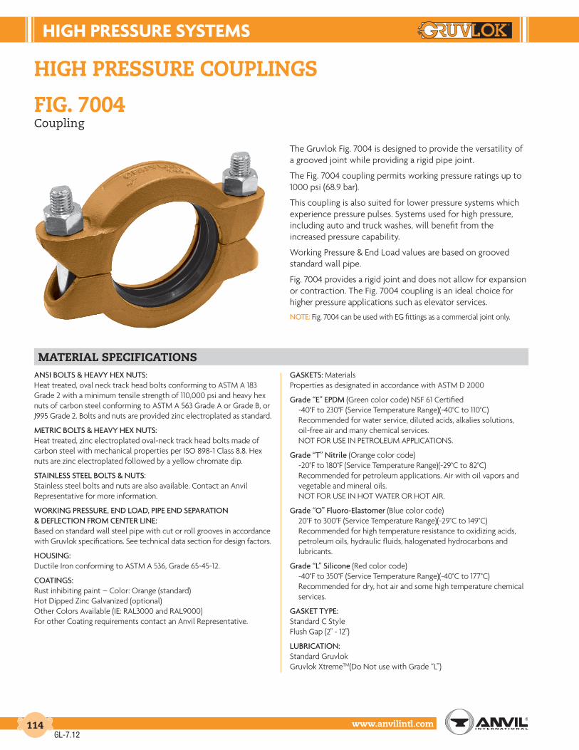
high pressure systems
www.anvilintl.com114
HIGH PRESSURE COUPLINGS
FIG. 7004Coupling
The Gruvlok Fig. 7004 is designed to provide the versatility of a grooved joint while providing a rigid pipe joint.
The Fig. 7004 coupling permits working pressure ratings up to 1000 psi (68.9 bar).
This coupling is also suited for lower pressure systems which experience pressure pulses. Systems used for high pressure, including auto and truck washes, will benefit from the increased pressure capability.
Working Pressure & End Load values are based on grooved standard wall pipe.
Fig. 7004 provides a rigid joint and does not allow for expansion or contraction. The Fig. 7004 coupling is an ideal choice for higher pressure applications such as elevator services.
NOTE: Fig. 7004 can be used with EG fittings as a commercial joint only.
matERIaL SPECIFICatIONSANSI BOLTS & HEAVY HEX NUTS:Heat treated, oval neck track head bolts conforming to ASTM A 183 Grade 2 with a minimum tensile strength of 110,000 psi and heavy hex nuts of carbon steel conforming to ASTM A 563 Grade A or Grade B, or J995 Grade 2. Bolts and nuts are provided zinc electroplated as standard.
METRIC BOLTS & HEAVY HEX NUTS:Heat treated, zinc electroplated oval-neck track head bolts made of carbon steel with mechanical properties per ISO 898-1 Class 8.8. Hex nuts are zinc electroplated followed by a yellow chromate dip.
STAINLESS STEEL BOLTS & NUTS:Stainless steel bolts and nuts are also available. Contact an Anvil Representative for more information.
WORKING PRESSURE, END LOAD, PIPE END SEPARATION & DEFLECTION FROM CENTER LINE:Based on standard wall steel pipe with cut or roll grooves in accordance with Gruvlok specifications. See technical data section for design factors.
HOUSING:Ductile Iron conforming to ASTM A 536, Grade 65-45-12.
COATINGS:Rust inhibiting paint – Color: Orange (standard) Hot Dipped Zinc Galvanized (optional) Other Colors Available (IE: RAL3000 and RAL9000) For other Coating requirements contact an Anvil Representative.
GASKETS: MaterialsProperties as designated in accordance with ASTM D 2000
Grade “E” EPDM (Green color code) NSF 61 Certified -40°F to 230°F (Service Temperature Range)(-40°C to 110°C) Recommended for water service, diluted acids, alkalies solutions, oil-free air and many chemical services. NOT FOR USE IN PETROLEUM APPLICATIONS.
Grade “T” Nitrile (Orange color code) -20°F to 180°F (Service Temperature Range)(-29°C to 82°C) Recommended for petroleum applications. Air with oil vapors and vegetable and mineral oils. NOT FOR USE IN HOT WATER OR HOT AIR.
Grade “O” Fluoro-Elastomer (Blue color code) 20°F to 300°F (Service Temperature Range)(-29°C to 149°C) Recommended for high temperature resistance to oxidizing acids, petroleum oils, hydraulic fluids, halogenated hydrocarbons and lubricants.
Grade “L” Silicone (Red color code) -40°F to 350°F (Service Temperature Range)(-40°C to 177°C) Recommended for dry, hot air and some high temperature chemical services.
GASKET TYPE: Standard C Style Flush Gap (2" - 12")
LUBRICATION: Standard Gruvlok Gruvlok XtremeTM(Do Not use with Grade “L”)
GL-7.12

HIGH PrESSurE SYStEMS
Intro
duct
ion
Coup
lings
Outle
tsFi
tting
sVa
lves
&
Acce
ssor
ies
High
Pres
sure
DI-L
OK®
Nipp
les
Plai
n-En
dFi
tting
sHD
PECo
uplin
gsSo
ck-It
®
Fitti
ngs
Stai
nles
sSt
eel M
etho
dRo
ll Gr
oove
rsIn
stal
latio
n&
Ass
embl
ySp
ecia
lCo
atin
gsDe
sign
Serv
ices
Tech
nica
lDa
taM
aste
r For
mat
3 Pa
rt Sp
ecs.
Pict
oria
lIn
dex
CTS
Copp
er
Syst
em
www.anvilintl.com 115
FIGurE 7004 couPLInG
Nominal Size O.D. Max. Wk.
PressureMax. End
LoadRange of Pipe
End SeparationCoupling Dimensions Coupling Bolts Approx.
Wt. Ea.X Y Z Qty. SizeIn./DN(mm) In./mm PSI/bar Lbs./kN In./mm In./mm In./mm In./mm In./mm Lbs./Kg
2 2.375 1000 4,430 0 -1⁄32 35⁄8 61⁄4 17⁄8 2 5⁄8 x 23⁄4 3.950 60.3 68.9 19.7 0 - 0.79 92 159 48 – 1.8
21⁄2 2.875 1000 6,492 0 -1⁄32 41⁄4 67⁄8 17⁄8 2 5⁄8 x 31⁄2 4.665 73.0 68.9 28.9 0 - 0.79 108 175 48 M16 x 85 2.1
3 3.500 1000 9,621 0 -1⁄32 47⁄8 71⁄2 17⁄8 2 5⁄8 x 31⁄2 5.280 88.9 68.9 42.8 0 - 0.79 124 191 48 M16 x 85 2.4
4 4.500 1000 15,904 0 -3⁄32 61⁄4 91⁄2 21⁄4 2 3⁄4 x 41⁄2 8.6100 114.3 68.9 70.8 0 - 2.38 159 241 57 M20 x 110 3.9
5 5.563 1000 24,306 0 -3⁄32 71⁄2 11 21⁄4 2 7⁄8 x 51⁄2 14.0125 141.3 68.9 108.1 0 - 2.38 191 279 57 M22 x 150 6.4
6 6.625 1000 34,472 0 -3⁄32 83⁄4 121⁄8 21⁄4 2 7⁄8 x 51⁄2 15.5150 168.3 68.9 153.3 0 - 2.38 222 308 57 M22 x 150 7.0
8 8.625 800 46,741 0 -3⁄32 111⁄8 147⁄8 25⁄8 2 1 x 51⁄2 25.6200 219.1 55.2 207.9 0 - 2.38 283 378 67 – 11.6
10 10.750 800 72,610 0 -3⁄32 131⁄2 17 25⁄8 2 1 x 61⁄2 32.3250 273.1 55.2 323.0 0 - 2.38 343 432 67 – 14.7
12 12.750 800 102,141 0 -3⁄32 157⁄8 191⁄4 25⁄8 2 1 x 61⁄2 43.9300 323.9 55.2 454.4 0 - 2.38 403 489 67 – 19.9
fiG. 7004Coupling
For additional details, see coupling data chart notes from page 17.See Installation & Assembly directions on page 169.Not for use in copper systems.
GL-6.11
Y
X
Z
Fig. 7004 with standard gasket

high pressure systems
www.anvilintl.com116
FIG. 7004 with EG® GasketCoupling
matErIal spEcIFIcatIonsANSI BOLTS & HEAVY HEX NUTS: Heat treated, oval neck track head bolts conforming to ASTM A 183 Grade 2 with a minimum tensile strength of 110,000 psi and heavy hex nuts of carbon steel conforming to ASTM A563 Grade A or Grade B, or J995 Grade 2. Bolts and nuts are provided zinc electroplated as standard.
METRIC BOLTS & HEAVY HEX NUTS: Heat treated, zinc electroplated oval-neck track head bolts made of carbon steel with mechanical properties per ISO 898-1 Class 8.8. Hex nuts are zinc electroplated followed by a yellow chromate dip.
STAINLESS STEEL BOLTS & NUTS: Stainless steel bolts and nuts are also available. Contact an Anvil Representative for more information.
WORKING PRESSURE, END LOAD, PIPE END SEPARATION & DEFLECTION FROM CENTER LINEBased on standard wall steel pipe with cut or roll grooves in accordance with Gruvlok specifications. See technical data section for design factors.
HOUSING: Ductile Iron conforming to ASTM A 536, Grade 65-45-12.
COATINGS: Rust inhibiting paint – Color: Orange (standard) Hot Dipped Zinc Galvanized (optional) Other Colors Available (IE: RAL3000 and RAL9000) For other Coating requirements contact an Anvil Representative.
GASKETS: Materials Properties as designated in accordance with ASTM D 2000
Grade “T” Nitrile (Orange color code) EG Gasket -20°F to 180°F (Service Temperature Range)(-29°C to 82°C) Recommended for petroleum applications. Air with oil vapors and vegetable and mineral oils. NOT FOR USE IN HOT WATER OR HOT AIR.
GASKET TYPE: “EG” Style
LUBRICATION: Standard Gruvlok Gruvlok XtremeTM(Do Not use with Grade “L”)
The Gruvlok Fig. 7004 Coupling with EG® Gasket uses the specially designed “End Guard” gasket for use with “EG” grooved pipe. The “EG” gasket has a center rib which extends between the pipes in order to provide pipe end protection, which makes it ideally suited for internally lined or coated pipe applications.
The Fig. 7004 Coupling with EG® Gasket permits working pressure ratings up to 2500 psi (172.4 bar).
Working Pressure and End Load values are based on “EG” cut grooved extra heavy steel pipe. Fig. 7004 provides a rigid joint and does not allow for expansion or contraction. Beveled end pipe should not be used with “EG” gaskets.
GL-7.12

HIGH PrESSurE SYStEMS
Intro
duct
ion
Coup
lings
Outle
tsFi
tting
sVa
lves
&
Acce
ssor
ies
High
Pres
sure
DI-L
OK®
Nipp
les
Plai
n-En
dFi
tting
sHD
PECo
uplin
gsSo
ck-It
®
Fitti
ngs
Stai
nles
sSt
eel M
etho
dRo
ll Gr
oove
rsIn
stal
latio
n&
Ass
embl
ySp
ecia
lCo
atin
gsDe
sign
Serv
ices
Tech
nica
lDa
taM
aste
r For
mat
3 Pa
rt Sp
ecs.
Pict
oria
lIn
dex
CTS
Copp
er
Syst
em
www.anvilintl.com 117
fiG. 7004 with eG® GasketCoupling
For additional details, see coupling data chart notes on page 17.See Installation & Assembly directions on page 170.Not for use in copper systems.
FIGurE 7004 couPLInG WItH EG GASKEt
Nominal Size O.D. Max. Wk.
PressureMax. End
LoadRange of Pipe
End SeparationCoupling Dimensions Coupling Bolts Approx.
Wt. Ea. X Y Z Qty. SizeIn./DN(mm) In./mm PSI/bar Lbs./kN In./mm In./mm In./mm In./mm In./mm Lbs./Kg
2 2.375 2500 11,075 0 -1⁄32 35⁄8 61⁄4 17⁄8 2 5⁄8 x 23⁄4 4.150 60.3 172.4 49.27 0 - 0.79 92 159 48 – 1.9
21⁄2 2.875 2500 16,230 0 -1⁄32 41⁄4 67⁄8 17⁄8 2 5⁄8 x 31⁄2 5.165 73.0 172.4 72.19 0 - 0.79 108 175 48 M16 x 85 2.3
3 3.500 2500 24,053 0 -1⁄32 47⁄8 71⁄2 17⁄8 2 5⁄8 x 31⁄2 5.580 88.9 172.4 106.99 0 - 0.79 124 191 48 M16 x 85 2.5
4 4.500 2500 39,761 0 -3⁄32 61⁄4 91⁄2 21⁄4 2 3⁄4 x 41⁄2 9.0100 114.3 172.4 176.86 0 - 2.38 159 241 57 M20 x 110 4.1
6 6.625 2000 68,943 0 -3⁄32 83⁄4 121⁄8 21⁄4 2 7⁄8 x 51⁄2 15.5150 168.3 137.9 306.67 0 - 2.38 222 308 57 M22 x 150 7.0
8 8.625 1500 87,639 0 -3⁄32 111⁄8 147⁄8 25⁄8 2 1 x 51⁄2 25.6200 219.1 103.4 389.84 0 - 2.38 283 378 67 – 11.6
10 10.750 1250 113,453 0 -3⁄32 131⁄2 17 25⁄8 2 1 x 61⁄2 32.3250 273.1 86.2 504.66 0 - 2.38 343 432 67 – 14.7
12 12.750 1250 159,595 0 -3⁄32 157⁄8 191⁄4 25⁄8 2 1 x 61⁄2 43.9300 323.9 86.2 709.92 0 - 2.38 403 489 67 – 19.9
GL-6.11
Y
X
Z
Fig. 7004 with “EG” gasket

HIGH PrESSurE SYStEMS
www.anvilintl.com118
FIGurE 7051 EG, HIGH PrESSurE 45° Lr ELBoW
Nominal Size O.D. Center
To-EndApprox. Wt. Ea.
In./DN(mm) In./mm In./mm Lbs./Kg
2 2.375 2 1.850 60.3 51 0.821⁄2 2.875 21⁄4 2.965 73.0 57 1.33 3.500 21⁄2 4.380 88.9 64 2.04 4.500 3 7.5
100 114.3 76 3.46 6.625 31⁄2 16.5
150 168.3 89 7.5
FIGurE 7050 EG, HIGH PrESSurE 90° Lr ELBoW
Nominal Size O.D. Center
To-EndApprox. Wt. Ea.
In./DN(mm) In./mm In./mm Lbs./Kg
2 2.375 31⁄4 2.550 60.3 83 1.121⁄2 2.875 33⁄4 4.265 73.0 95 1.93 3.500 41⁄4 6.080 88.9 108 2.74 4.500 5 11.0
100 114.3 127 5.06 6.625 61⁄2 27.2
150 168.3 165 12.48 8.625 * *
200 219.1 * *10 10.750 * *250 273.0 * *12 12.750 * *300 323.9 * *
Nominal Size O.D.
In./DN(mm) In./mm
3 3.50080 88.94 4.500
100 114.35 5.563
140 141.36 6.625
150 168.38 8.625
200 219.1
Nominal Size O.D.
In./DN(mm) In./mm
1 1.31525 33.711⁄4 1.66032 42.411⁄2 1.90040 48.32 2.37550 60.321⁄2 2.87565 73.0
FIttInG SIZE
hiGh pressure fittinGs
Gruvlok End Guard fittings are fabricated from extra heavy (XS) materials. The groove conforms to Gruvlok End Guard cut grooving specification. These fittings may be used for high pressure systems and where lined or coated fittings are required. Gruvlok EG fittings conform to NACE STD-RP-04-72 (Contact an Anvil Representative with specific service details). End Guard fittings should only be used with Series 7004 Couplings and EG Gasket.
material specifications
fiG. 7050 eG - High Pressure 90° LR Elbow fiG. 7051 eG - High Pressure 45° LR Elbow
ELBOWS: Extra strong forged steel fittings conforming to ASTM A 234 with welded tangents of schedule 80 steel pipe conforming to ASTM A 106.
TEES & CROSSES: Segment welded schedule 80 steel pipe conforming to ASTM A 106.
COATINGS: Rust inhibiting paint – Color: Orange (standard) Hot Dipped Zinc Galvanized (optional) Other Colors Available (IE: RAL3000 and RAL9000) For other Coating requirements contact an Anvil Representative.
C to E
O.D.
C to E
O.D.
* Contact an Anvil Representative for more information.
GL-7.12

HIGH PrESSurE SYStEMS
Intro
duct
ion
Coup
lings
Outle
tsFi
tting
sVa
lves
&
Acce
ssor
ies
High
Pres
sure
DI-L
OK®
Nipp
les
Plai
n-En
dFi
tting
sHD
PECo
uplin
gsSo
ck-It
®
Fitti
ngs
Stai
nles
sSt
eel M
etho
dRo
ll Gr
oove
rsIn
stal
latio
n&
Ass
embl
ySp
ecia
lCo
atin
gsDe
sign
Serv
ices
Tech
nica
lDa
taM
aste
r For
mat
3 Pa
rt Sp
ecs.
Pict
oria
lIn
dex
CTS
Copp
er
Syst
em
www.anvilintl.com 119
FIGurE 7060 EG - HIGH PrESSurE tEE
Nominal Size O.D. Center
To-EndApprox. Wt. Ea.
In./DN(mm) In./mm In./mm Lbs./Kg
2 2.375 31⁄4 3.350 60.3 83 1.521⁄2 2.875 33⁄4 5.165 73.0 95 2.33 3.500 41⁄4 9.380 88.9 108 4.24 4.500 5 15.9
100 114.3 127 7.26 6.625 61⁄2 38.5
150 168.3 165 17.5
hiGh pressure fittinGs
fiG. 7662 eG - High Pressure Header TeefiG. 7060 eG - High Pressure Tee
fiG. 7068 eG - High Pressure Cross
FIG. 7662 EG - HIGH PrESSurE HEAdEr tEE
Nominal Size O.D. Center
To-EndApprox. Wt. Ea.
In./DN(mm) In./mm In./mm Lbs./Kg
2 2.375 61⁄2 4.950 60.3 165 2.22 2.375 5 3.650 60.3 127 1.6
FIG. 7068 EG - HIGH PrESSurE croSS
Nominal Size O.D. Center
To-EndApprox. Wt. Ea.
In./DN(mm) In./mm In./mm Lbs./Kg
2 2.375 31⁄4 3.950 60.3 83 1.821⁄2 2.875 33⁄4 6.865 73.0 95 3.13 3.500 41⁄4 11.580 88.9 108 5.24 4.500 5 19.3
100 114.3 127 8.86 6.625 61⁄2 46.0
150 168.3 165 20.9
C to E
C to E
O.D.
C to E
C to E
O.D.
C to E
O.D.
GL-7.12

ctS coPPEr SYStEM
www.anvilintl.com120
The Gruvlok® CTS Copper System offers an installer of large diameter copper tubing an alternative to the conventional soldering and brazing.
This new grooved copper system is faster and easier to install. Temperature and weather conditions are no longer a factor when planning installations. There is no sweating or brazing as this system requires only a wrench for assembly on grooved end pipe.
The copper system is “flame-free”. Essentially you save time and enjoy a very reliable system that is both versatile and economical. Safety is a factor as there is no fire hazard, especially in a retrofit installation. The ease of assembly is a great benefit in new construction and ease of disassembly is ideal for renovation, retrofit or expansion.
• Fast and easy to assemble.
• No flame, no sweat
• Each joint has a union.
• Provides rigidity
• Easily roll grooved
• Proven joint reliability
• Accepted and approved.
• Economical and reliable
Gruvlok® cts copper system
benefits
GL-6.11

ctS coPPEr SYStEM
Intro
duct
ion
Coup
lings
Outle
tsFi
tting
sVa
lves
&
Acce
ssor
ies
High
Pres
sure
DI-L
OK®
Nipp
les
Plai
n-En
dFi
tting
sHD
PECo
uplin
gsSo
ck-It
®
Fitti
ngs
Stai
nles
sSt
eel M
etho
dRo
ll Gr
oove
rsIn
stal
latio
n&
Ass
embl
ySp
ecia
lCo
atin
gsDe
sign
Serv
ices
Tech
nica
lDa
taM
aste
r For
mat
3 Pa
rt Sp
ecs.
Pict
oria
lIn
dex
CTS
Copp
er
Syst
em
www.anvilintl.com 121
fiG. 6400Rigid Coupling
The Figure 6400 Rigid Coupling is specially designed to provide a rigid pipe connection to meet the specific demands of copper tubing installation size 2"-8". Fast and easy swing-over installation of the rugged lightweight housing produces a secure rigid pipe joint. Available with Grade “EP” Copper EPDM flush gap style gasket. Gasket has service temperature range of -40˚F to +250˚F. NSF 61 Certified for cold +86˚F (+30˚C) and hot +180˚F (+82˚C) potable water service.
HOUSING: Ductile iron conforming to ASTM A-536, Grade 65-45-12
COATINGS: Rust inhibiting enamel paint — Color: Copper For other coating requirements contact your Anvil Representative.
ANSI BOLTS AND HEAVY HEX NUTS: Heat treated carbon steel oval neck bolts conforming to the physical properties of ASTM A 183 with a minimum tensile strength of 110,000 PSI. Bolts and nuts are provided zinc electroplated as standard.
GASKETS: Grade “EP” EPDM Flush Gap Gasket (Green and Red Color Code) Service Temperature Range: -40°F to +250°F(-40°C to +121°C) Recommended for water service, diluted acids, alkaline solutions, oil-free air and many chemical services. NOT FOR USE IN PETROLEUM APPLICATIONS.
NSF 61 Certified for cold +86˚F (+30˚C) and hot +180˚F (+82˚C) potable water service.
FIGurE 6400 rIGId couPLInG
Nominal Size
CopperTube
Diameter
Max Wk.Pressure
MaxEndLoad
Range ofPipe End
Separation
Coupling Dimensions Coupling BoltsApprox.Wt. Ea.
X Y Z Qty. Size
In. In./mm PSI/bar Lbs./kN In./mm In./mm In./mm Lbs./Kg
2 2.12554.0
30020.7
10634.73
0 - 0.080 - 2.0
3.0076
5.00127
1.6843 2 3⁄8 x 21⁄4 1.53
0.69
21⁄2 2.62566.7
30020.7
16237.22
0 - 0.080 - 2.0
3.5089
5.50140
1.6843 2 3⁄8 x 21⁄4 1.78
0.81
3 3.12579.4
30020.7
230010.23
0 - 0.080 - 2.0
4.18106
6.28159
1.6843 2 1⁄2 x 3 2.76
1.25
4 4.125104.8
30020.7
400717.82
0 - 0.130 - 2.4
5.20132
7.50191
1.7043 2 1⁄2 x 3 3.27
1.48
5 5.125130.2
30020.7
618627.51
0 - 0.130 - 2.4
6.20157
9.10231
1.8046 2 5⁄8 x 31⁄4 4.71
2.14
6 6.125155.6
30020.7
883539.30
0 - 0.130 - 2.4
7.20183
10.20259
1.8046 2 5⁄8 x 31⁄4 5.24
2.38
8 8.125206.4
30020.7
1554769.15
0 - 0.130 - 2.4
9.32237
12.40315
2.0051 2 5⁄8 x 31⁄4 7.67
3.48
Pressure ratings and end loads are based on use with ASTM B88 Type K or L tubing. For pressure ratings on Type M and DWV, contact your Anvil Representative.See Installation & Assembly directions on page 159.
material specifications
Y Z
X
GL-7.12

ctS coPPEr SYStEM
www.anvilintl.com122
CTS Copper Fittings are produced with groove and cup ends in a variety of fitting configurations. The fittings are constructed to ASTM B75 UNS C12200 with a minimum copper content of 99.9%. Fitting pressure ratings match the ratings of the Figure 6400 Coupling.
dIMEnSIonS/WEIGHtS — ELBoWS, tEES & cAPS
NominalSize
Copper TubeDiameter
Fig. 605090˚ Elbow
Fig. 605145˚ Elbow
Fig. 6060Tee
Fig. 6074Cap
C to E Wt. Ea. C to E Wt. Ea. C to E Wt. Ea. E to E Wt. Ea.
In. In./mm In./mm Lbs./kg In./mm Lbs./kg In./mm Lbs./kg In./mm Lbs./kg
2 2.12554.0
2.9174
0.750.34
2.1956
0.610.28
2.6968
1.450.66
2.0051
0.360.16
21⁄2 2.62566.7
3.3184
1.150.52
2.3159
0.890.40
3.2081
2.371.07
2.0051
0.500.23
3 3.12579.4
3.8197
1.880.85
2.5966
1.380.63
3.5289
3.381.53
2.0051
0.690.31
4 4.125104.8
4.75121
4.071.85
3.1981
2.991.36
4.25108
5.772.62
2.0051
1.150.52
5 5.125130.2
5.94151
6.943.15
3.2583
4.001.81
5.94151
12.845.82
2.7570
1.810.82
6 6.125155.6
6.94176
11.125.04
3.6392
6.162.79
6.94176
21.009.52
3.1380
2.681.22
8 8.125206.4
7.75197
21.819.89
4.25108
13.666.20
7.75197
21.819.89
––
––
fiG. 6050 fiG. 6051 fiG. 6060 fiG. 6074
cts copper fittinGs
C to E
C to E
E to E
C to E
GL-7.12

ctS coPPEr SYStEM
Intro
duct
ion
Coup
lings
Outle
tsFi
tting
sVa
lves
&
Acce
ssor
ies
High
Pres
sure
DI-L
OK®
Nipp
les
Plai
n-En
dFi
tting
sHD
PECo
uplin
gsSo
ck-It
®
Fitti
ngs
Stai
nles
sSt
eel M
etho
dRo
ll Gr
oove
rsIn
stal
latio
n&
Ass
embl
ySp
ecia
lCo
atin
gsDe
sign
Serv
ices
Tech
nica
lDa
taM
aste
r For
mat
3 Pa
rt Sp
ecs.
Pict
oria
lIn
dex
CTS
Copp
er
Syst
em
www.anvilintl.com 123
dIMEnSIonS/WEIGHtS – rEducInG tEES
Nominal Size
Fig. 6061Groove x Groove x Groove
Fig. 6064Groove x Groove x Cup
C to E C to ØE Wt. Ea C to E C to ØE Cup Length Wt Ea.
In. In./mm In./mm Lbs./kg In./mm In./mm In./mm Lbs./kg
2 x 2 x 3⁄4 ––
––
––
2.2056
1.9850
0.7519
0.880.40
2 x 2 x 1 ––
––
––
2.3359
2.2056
0.9123
1.030.47
2 x 2 x 11⁄4 ––
––
––
2.4863
2.3560
0.9725
1.120.51
2 x 2 x 11⁄2 ––
––
––
2.5565
2.2858
1.0928
1.250.57
21⁄2 x 21⁄2 x 3⁄4 ––
––
––
2.2758
2.1855
0.7519
1.250.57
21⁄2 x 21⁄2 x 1 ––
––
––
2.4061
2.4061
0.9123
1.380.63
21⁄2 x 21⁄2 x 11⁄4 ––
––
––
2.5264
2.5765
0.9725
1.560.71
21⁄2 x 21⁄2 x 11⁄2 ––
––
––
2.7069
2.6868
1.0928
1.880.85
21⁄2 x 21⁄2 x 2 3.2883
3.3886
2.541.15
––
––
––
––
3 x 3 x 3⁄4 ––
––
––
2.4562
2.6066
0.7519
1.880.85
3 x 3 x 1 ––
––
––
2.5465
2.7971
0.9123
2.040.93
3 x 3 x 11⁄4 ––
––
––
2.6367
2.8973
0.9725
2.130.97
3 x 3 x 11⁄2 ––
––
––
2.8572
3.0076
1.0928
2.251.02
3 x 3 x 2 3.0076
3.3886
2.901.32
––
––
––
––
3 x 3 x 21⁄2 3.2583
3.5089
3.161.43
––
––
––
––
4 x 4 x 3⁄4 ––
––
––
2.9575
3.0076
0.7519
3.631.65
4 x 4 x 1 ––
––
––
3.1079
3.2282
0.9123
3.941.79
4 x 4 x 11⁄4 ––
––
––
3.2583
3.4788
0.9725
4.241.92
4 x 4 x 11⁄2 ––
––
––
3.3585
3.6593
1.0928
4.472.03
4 x 4 x 2 3.6693
4.13105
5.142.33
––
––
––
––
4 x 4 x 21⁄2 3.94100
4.06103
5.362.43
––
––
––
––
4 x 4 x 3 4.19106
4.16106
5.882.67
––
––
––
––
5 x 5 x 3 3.7595
4.63118
7.453.38
––
––
––
––
5 x 5 x 4 4.25108
4.56116
8.133.69
––
––
––
––
6 x 6 x 21⁄2 3.6392
5.13130
9.424.27
––
––
––
––
6 x 6 x 3 3.6994
5.19132
10.064.56
––
––
––
––
6 x 6 x 4 4.19106
5.13130
10.864.93
––
––
––
––
6 x 6 x 5 4.69119
5.19132
12.735.77
––
––
––
––
reducinG tees
fiG. 6061
fiG. 6064
C to E
C to ØE
C to E
C to ØECup Length
GL-6.11

ctS coPPEr SYStEM
www.anvilintl.com124
concentricreducers
dIMEnSIonS/WEIGHtS – rEducErS
NominalSize
Fig. 6072Groove x Groove
Fig. 6075Groove x Cup
E to E Wt. Ea E to E Cup Length Wt Ea.
In. In./mm Lbs./kg In./mm In./mm Lbs./kg
2 x 1 ––
––
2.7068.6
0.9123.1
0.320.15
2 x 11⁄4 ––
––
3.0076.2
0.9724.6
0.360.16
2 x 11⁄2 ––
––
2.9474.7
1.0927.7
0.380.17
21⁄2 x 1 ––
––
3.2582.6
0.9123.1
0.530.24
21⁄2 x 11⁄4 ––
––
3.5289.4
0.9724.6
0.590.27
21⁄2 x 11⁄2 ––
––
3.4587.6
1.0927.7
0.590.27
21⁄2 x 2 3.2983.6
0.580.26
3.3083.8
1.3434.0
0.580.26
3 x 11⁄2 ––
––
3.6893.5
1.0927.7
0.840.38
3 x 2 2.5063.5
0.580.26
4.10104.1
1.3434.0
0.970.44
3 x 21⁄2 2.5063.5
0.620.28
––
––
––
4 x 2 4.75120.7
1.710.78
4.75120.7
1.3434.0
1.760.80
4 x 21⁄2 3.0076.2
1.120.51
––
––
––
4 x 3 3.0076.2
1.220.55
––
––
––
5 x 3 3.8898.6
2.110.96
––
––
––
5 x 4 3.3885.9
1.970.89
––
––
––
6 x 3 4.38111.3
2.961.34
––
––
––
6 x 4 3.8898.6
2.871.30
––
––
––
6 x 5 3.3885.9
2.781.26
––
––
––
8 x 6 5.00127.0
6.602.99
––
––
––
fiG. 6072 fiG. 6075
fiG. 6084Flange Adapter
The Gruvlok® Fig. 6084 Flange Adapter allows for direct connection of Class 125 or Class 150 flanged components to the CTS Copper System. The CTS Copper Flange Adapter (Sizes 2" thru 6") conforms to ANSI class 125/150 bolt patterns and is rated at 300 PSIG (20.7 bar). The flange is powder coated with Nylon-11.
FIGurE 6084 FLAnGE AdAPtEr
NominalSize
Copper TubeDiameter E to E Approx.
Wt. Ea.
In. In./mm In./mm Lbs./kg
2 2.12554.0
3.076.2
0.850.39
2½ 2.62566.7
3.588.9
1.340.61
3 3.12579.4
3.588.9
1.730.78
4 4.125104.8
3.588.9
2.431.10
5 5.125130.2
3.588.9
3.271.48
6 6.125155.6
4.0101.6
4.782.17
E to E E to ECup
E to E
GL-7.12

ctS coPPEr SYStEM
Intro
duct
ion
Coup
lings
Outle
tsFi
tting
sVa
lves
&
Acce
ssor
ies
High
Pres
sure
DI-L
OK®
Nipp
les
Plai
n-En
dFi
tting
sHD
PECo
uplin
gsSo
ck-It
®
Fitti
ngs
Stai
nles
sSt
eel M
etho
dRo
ll Gr
oove
rsIn
stal
latio
n&
Ass
embl
ySp
ecia
lCo
atin
gsDe
sign
Serv
ices
Tech
nica
lDa
taM
aste
r For
mat
3 Pa
rt Sp
ecs.
Pict
oria
lIn
dex
CTS
Copp
er
Syst
em
www.anvilintl.com 125
SErIES 6700 ctS coPPEr ButtErFLY VALVE dIMEnSIonS
NominalSize
Copper Tube
Diameter
DimensionsWeight
A B C D E F G H J
In. In./mm In./mm In./mm In./mm In./mm In./mm In./mm In./mm In./mm In./mm Lbs./kg
21⁄22.625 3.77 2.22 2.63 3.83 7.20 10.50 12.39 2.00 4.43 466.7 95.8 56.4 66.7 97.3 182.5 266.7 314.6 50.8 112.5 1.8
33.125 3.77 2.60 3.13 4.08 7.84 10.50 12.39 2.00 4.43 579.4 95.8 65.9 79.4 130.5 198.2 266.7 314.6 50.8 112.5 2.3
44.125 4.63 3.10 4.13 4.72 8.97 10.50 12.81 2.00 4.43 8104.8 117.6 78.7 104.9 119.9 227.8 266.7 325.5 50.8 112.5 3.8
55.125 5.88 3.85 5.13 5.22 10.27 10.50 13.44 2.00 4.43 14130.2 149.4 97.8 130.2 132.6 260.9 266.7 341.4 50.8 112.5 6.4
66.125 5.88 4.36 6.13 5.75 11.31 10.50 13.44 2.00 4.43 18155.6 149.4 110.8 155.6 146.2 287.3 266.7 341.4 50.8 112.5 8.1
VALVE BODY: ASTM B584 C89836; Bronze, Low Lead
DISC: ASTM A536 Gr. 65-45-12; Ductile Iron
DISC ENCAPSUALTION:Grade “EP” EPDM Rubber: Service temperature range: -40˚F to +250˚F (-40˚C to +121˚C). Recommended for water service, diluted acids, alkaline solutions, and oil-free air. NOT RECOMMENDED FOR USE IN PETROLEUM APPLICATIONS.
UPPER & LOWER SHAFTS: Stainless Steel Type 17-4PH; ASTM A564
CERTIFICATIONS: ANSI/NSF61 for use in Cold +86F(+30C) and Hot +180F(+82C) potable water systems. Annex G. UPC.
The lever handle bronze body butterfly valve is designed for use with grooved copper tubing (CTS), fittings and couplings. This valve features a 10 position lever handle, bronze body and EPDM rubber encapsulated disc. Both bronze valve body and the EPDM rubber disc obtained certification to ANSI/NSF 61 for use in potable water systems and is rated to 300 PSI.
material specifications
GL-6.11
series 6700CTS Copper Butterfly Valve
Hot Water / Annex G
NSF/ANSI 61
D
F
G
A
E
øCB
H
J

ctS coPPEr SYStEM
www.anvilintl.com126
GruVLoK ctS coPPEr ButtErFLY VALVE SErIES 6700 (ordErInG InForMAtIon)
Sample Part Number 4" 6711-1 ––>
4" 67 1 1 - 1Size Series Disc Coating Operator Shaft
21/2" - 6" 6700 1 - EPDM (Grade EP) 0 - None 1 - 17-4 PH S/S
1 - 10 Pos. Handlever
series 6700CTS Copper Butterfly Valve
Values for flow of water at +60˚F (+16˚C) QCv = ∆PWhere: Cv = Flow coefficient Q = Flow (GPM) ∆P = Pressure drop (psi)
.1 .2 .3 .4 .5 .6 .7 .8 .9 2 3 4 5 6 7 8 91 10 20
20
10
30
405060708090100
200
300
400500600700800900
1000
2000
3000
400050006000700080009000
10000
20000
21/2"
3"
4"
5"
6"
Pressure Drop - psig
Val
ve S
ize
Flo
w (
Wat
er)
- g
pm
GL-6.11

dI-LoK® nIPPLES
Intro
duct
ion
Coup
lings
Outle
tsFi
tting
sVa
lves
&
Acce
ssor
ies
High
Pres
sure
DI-L
OK®
Nipp
les
Plai
n-En
dFi
tting
sHD
PECo
uplin
gsSo
ck-It
®
Fitti
ngs
Stai
nles
sSt
eel M
etho
dRo
ll Gr
oove
rsIn
stal
latio
n&
Ass
embl
ySp
ecia
lCo
atin
gsDe
sign
Serv
ices
Tech
nica
lDa
taM
aste
r For
mat
3 Pa
rt Sp
ecs.
Pict
oria
lIn
dex
CTS
Copp
er
Syst
em
www.anvilintl.com 127
fiG. 7091Gruvlok® DI-LOK™ CTS Groove x IPS Groove Dielectric Fitting
The Gruvlok Fig. 7091 DI-LOK Fitting prevents the formation of a galvanic cell between grooved end steel pipe and copper tube. The separation of copper from steel by the fitting virtually eliminates the galvanic cell created by the dissimilar metals.
The DI-LOK Fitting is designed for use at temperatures from -40˚F to 230˚F (-40˚C to 110˚C) and pressures to 300 psig (20.7 bar) in a wide range of applications.
material specifications
HOUSING: Seamless Carbon Steel to ASTM A106
COATING: Nylon conforming to ANSI/NSF-61
GL-7.12
FIGurE 7091 dI-LoK nIPPLE
Nominal SizeCopper (CTS) Steel (IPS)
End to End Approx.Wt. Ea.D
ActualD
ActualIPS In./mm In./mm In./mm Lbs./Kg
2 2.125 2.375 4.0 1.3250 53.98 60.33 101.60 .6021⁄2 2.625 2.875 6.0 2.8565 66.68 73.03 152.40 1.293 3.125 3.500 6.0 4.2780 79.38 88.90 152.40 1.944 4.125 4.500 6.0 5.62
100 104.78 114.30 152.40 2.556 6.125 6.625 6.0 9.66
150 155.58 168.28 152.40 4.38
For installation and assembly of grooved-end connections, see “Fig. 6400 Gruvlok Rigid Coupling”, “Fig. 7400 Gruvlok Rigidlite Coupling” and “Fig. 7012 Gruvlok Flange”.
E to E
IPS D CTSD

PLAIn-End FIttInGS
www.anvilintl.com128
FIGurE 7005 rouGHnEcK® couPLInG
Nominal Size O.D. Max. Wk.
PressureMax. End
LoadNo. of
GrippersCoupling Dimensions Coupling Bolts Specified Torque § Approx.
Wt. Ea.X Y Z Qty. Size Min. MaxIn./DN(mm) In./mm PSI/bar Lbs./kN In./mm In./mm In./mm In./mm Ft.-Lbs./N-m Ft.-Lbs./N-m Lbs./Kg
2 2.375 750 3,323 8 33⁄4 63⁄8 31⁄2 2 5⁄8 x 31⁄4 150 190 6.650 60.3 51.7 14.78 95 162 89 - 203 257 3.0
21⁄2 2.875 600 3,895 8 41⁄4 71⁄8 31⁄2 2 5⁄8 x 31⁄4 150 190 7.465 73.0 41.4 17.33 108 181 89 - 203 257 3.4
3 3.500 600 5,773 8 47⁄8 81⁄8 31⁄2 2 3⁄4 x 41⁄2 200 250 10.580 88.9 41.4 25.68 124 206 89 - 271 339 4.8
4 4.500 450 7,157 8 63⁄8 93⁄8 41⁄8 2 3⁄4 x 41⁄2 200 250 16.4100 114.3 31.0 31.84 162 238 105 - 271 339 7.4
5 5.563 350 8,507 8 71⁄2 111⁄8 43⁄8 2 7⁄8 x 5 250 300 23.8125 141.3 24.1 37.84 191 283 111 - 339 406 10.8
6 6.625 300 10,341 12 83⁄4 127⁄8 43⁄8 2 1 x 6 250 300 31.7150 168.3 20.7 46.00 222 327 111 - 339 406 14.4
8 8.625 300 17,528 12 107⁄8 141⁄2 41⁄2 4 7⁄8 x 5 250 300 38.6200 219.1 20.7 77.97 276 368 114 - 339 406 17.5
10 10.750 300 27,229 8 125⁄8 18 53⁄8 4 1 x 61⁄2 500 600 40250 273.1 20.7 121.12 321 457 137 - 678 814 18.1
12 12.750 250 31,919 12 147⁄8 201⁄4 53⁄8 4 1 x 61⁄2 550 700 56300 323.9 17.2 141.98 378 514 137 - 746 949 25.4
14 14.000 200 30,788 12 163⁄4 221⁄8 61⁄4 4 1 x 61⁄2 550 700 88350 355.6 13.8 136.95 425 562 159 - 746 949 39.9
16 16.000 150 30,159 12 183⁄4 24 61⁄4 4 1 x 61⁄2 550 700 95400 406.4 10.3 134.15 476 610 159 - 746 949 43.1
fiG. 7005Roughneck® Coupling
The Fig. 7005 Roughneck Coupling is an effective and reliable way of joining plain-end or beveled end pipe. The Roughneck Coupling is ideal for use in a variety of applications including mining, process piping, manifold piping and oilfield services. The unique gripper action provides a positive pipe joint and allows for working pressure ratings up to 750 PSI (52 bar).
material specificationsHOUSING: Ductile Iron conforming to ASTM A 536, Grade 65-45-12 or Malleable Iron conforming to ASTM A 47, Grade 32510.
BOLT & NUTS: Heat treated, oval-neck track head bolts conforming to ASTM A 183 Grade 2 with a minimum tensile strength of 110,000 psi and heavy hex nuts of carbon steel conforming to ASTM A 563 Grade A or Grade B, or J995 Grade 2. Bolts and nuts are provided zinc electroplated as standard.
GRIPPERS: 2"-8" heat treated, electroplated carbon steel. 10”-16” heat treated stainless steel.
COATINGS: Rust inhibiting paint - Color: Orange Standard Hot dipped Zinc Galvanized (Optional) Other Colors Available (IE: RAL3000 and RAL9000). For other Coating requirements contact an Anvil Representative.
GASKET: Grade E (EPDM) or Grade T (Nitrile) Elastomers with properties as designed by ASTM D 2000 for each gasket grade.
See Coupling data chart notes on page 17.§ – For additional Bolt Torque information, see page 190.Not for use in copper or PVC systems.See Installation & Assembly directions on page 168.
Working pressure and end load are based on a properly assembled Roughneck coupling with bolts fully torqued to the above specifications, on plain-end or beveled standard wall steel pipe and Gruvlok Plain- End Fittings.
Roughneck Couplings are designed to be used on plain-end pipe and Gruvlok Plain-End Fittings only. For externally coated pipe applications, contact an Anvil Representative.
Not recommended for use on steel pipe with a hardness greater than 150 Brinell, plastic, HDPE, cast iron or other brittle pipe.
*Bolt torque ratings shown must be applied at installation.
HousingGasket
PipeGrippers
GL-7.12
For Listings/Approval Details and Limitations,visit our website at www.anvilintl.com orcontact an Anvil® Sales Representative.

PLAIn-End FIttInGS
Intro
duct
ion
Coup
lings
Outle
tsFi
tting
sVa
lves
&
Acce
ssor
ies
High
Pres
sure
DI-L
OK®
Nipp
les
Plai
n-En
dFi
tting
sHD
PECo
uplin
gsSo
ck-It
®
Fitti
ngs
Stai
nles
sSt
eel M
etho
dRo
ll Gr
oove
rsIn
stal
latio
n&
Ass
embl
ySp
ecia
lCo
atin
gsDe
sign
Serv
ices
Tech
nica
lDa
taM
aste
r For
mat
3 Pa
rt Sp
ecs.
Pict
oria
lIn
dex
CTS
Copp
er
Syst
em
www.anvilintl.com 129
FIGurE 7050P 90° ELBoW
Nominal Size O.D. Center
To EndApprox. Wt. Ea.
In./DN(mm) In./mm In./mm Lbs./Kg
2 2.375 43⁄4 2.750 60.3 121 1.2
21⁄2 2.875 51⁄2 4.865 73.0 140 2.2
3 3.500 61⁄4 7.280 88.9 159 3.3
31⁄2 4.000 7 9.490 101.6 178 4.3
4 4.500 73⁄4 12.3100 114.3 197 5.6
5 5.563 91⁄2 13.4125 141.3 241 6.1
6 6.625 11 31150 168.3 279 14.1
8 8.625 11 38.7200 219.1 279 17.6
FIGurE 7060P tEE
Nominal Size O.D. Center
To EndApprox. Wt. Ea.
In./DN(mm) In./mm In./mm Lbs./Kg
2 2.375 41⁄4 3.550 60.3 108 1.6
21⁄2 2.875 43⁄4 6.265 73.0 121 2.8
3 3.500 51⁄8 8.680 88.9 130 3.9
31⁄2 4.000 51⁄2 1190 101.6 140 5.0
4 4.500 57⁄8 13.8100 114.3 149 6.3
5 5.563 67⁄8 21.7125 141.3 175 9.8
6 6.625 75⁄8 30.9150 168.3 194 14.0
8 8.625 10 61.1200 219.1 254 27.7
Nominal Size O.D.
In./DN(mm) In./mm
2 2.37550 60.321⁄2 2.87565 73.03 3.50080 88.931⁄2 4.00090 101.6
Nominal Size O.D.
In./DN(mm) In./mm
4 4.500100 114.35 5.563
140 141.36 6.625
150 168.38 8.625
200 219.1
FIttInG SIZE
Gruvlok plain-end fittinGs
Gruvlok plain-end fittings are manufactured to provide minimum pressure drop and uniform flow. Fittings are designed for use with the Fig. 7005 Roughneck Couplings only.
Gruvlok plain-end fittings are available in sizes through 8" nominal pipe size in a variety of styles. Depending on size and configuration, fittings are either segment-welded steel or forged steel.
Fittings are normally coated with a rust inhibiting paint. Other coatings including Hot Dipped Zinc Galvanizing, are available.
material specificationsSEGMENT WELDED STEEL FITTINGS: Sizes 2" - 4" Carbon Steel pipe conforming to ASTM A 53, Type “F”; Sizes 5" - 8"; Carbon Steel pipe conforming to ASTM A 53, Type “E” or “S”, Grade “B”.
STEEL FITTINGS: Forged Steel conforming to ASTM A 106.
ADAPTER FLANGES: Class 150 - Carbon Steel conforming to ANSI B16.5 Class 300 - Carbon Steel conforming to ANSI B16.5
fiG. 7050p - 90° Elbow fiG. 7051p - 45° Elbow fiG. 7060p - Tee
The Fitting Size Chart is used to determine the O.D. of the pipe that the fittings is to be used with. Gruvlok® Fittings are identified by either the Nominal size in inches or the Pipe O.D. In./mm.
FIGurE 7051P 45° ELBoW
Nominal Size O.D. Center
To EndApprox. Wt. Ea.
In./DN(mm) In./mm In./mm Lbs./Kg
2 2.375 31⁄8 2.050 60.3 79 0.9
21⁄2 2.875 31⁄2 3.565 73.0 89 1.6
3 3.500 33⁄4 4.880 88.9 95 2.2
31⁄2 4.000 4 6.290 101.6 102 2.8
4 4.500 41⁄4 8.0100 114.3 108 3.6
5 5.563 51⁄8 9.2125 141.3 130 4.2
6 6.625 53⁄4 18.5150 168.3 146 8.4
8 8.625 6 24.9200 219.1 152 11.3
C to E
O.D.
ot C
E O.D.
C to E
O.D.
GL-6.11

PLAIn-End FIttInGS
www.anvilintl.com130
Gruvlok plain-end fittinGs
fiG. 7068p - Cross fiG. 7069p - 45° Lateral fiG. 7071p - 90° True Wye
fiG. 7061p - Reducing Tee fiG. 7050lrp - 90° LR Elbow
FIGurE 7068P - croSS
Nominal Size O.D. Center
To EndApprox. Wt. Ea.
In./DN(mm) In./mm In./mm Lbs./Kg
2 2.375 41⁄4 4.450 60.3 108 2.021⁄2 2.875 43⁄4 7.865 73.0 121 3.53 3.500 51⁄8 10.780 88.9 130 4.931⁄2 4.000 51⁄2 13.790 101.6 140 6.24 4.500 57⁄8 17
100 114.3 149 7.75 5.563 67⁄8 26.7
125 141.3 175 12.16 6.625 75⁄8 37.7
150 168.3 194 17.18 8.625 10 74.6
200 219.1 254 33.8
FIGurE 7069P - 45° LAtErAL
Nominal Size O.D. Center to
Long EndCenter to Short End
Approx. Wt. Ea.
In./DN(mm) In./mm In./mm In./mm Lbs./Kg
2 2.375 71⁄4 23⁄4 5.150 60.3 184 70 2.321⁄2 2.875 73⁄4 3 9.565 73.0 197 76 4.33 3.500 83⁄4 31⁄4 12.880 88.9 222 83 5.831⁄2 4.000 10 31⁄2 20.090 101.6 254 89 9.14 4.500 103⁄4 33⁄4 22.2
100 114.3 273 95 10.15 5.563 123⁄4 4 38.0
125 141.3 324 102 17.26 6.625 14 41⁄2 54.0
150 168.3 356 114 24.58 8.625 18 6 92.0
200 219.1 457 152 41.7
FIGurE 7071P - 90° truE WYE
Nominal Size O.D. Center to
Long EndCenter to Short End
Approx. Wt. Ea.
In./DN(mm) In./mm In./mm In./mm Lbs./Kg
2 2.375 41⁄4 23⁄4 3.550 60.3 108 70 1.621⁄2 2.875 43⁄4 3 6.265 73.0 121 76 2.83 3.500 51⁄8 31⁄4 8.580 88.9 130 83 3.931⁄2 4.000 51⁄2 31⁄2 10.090 101.6 140 89 4.54 4.500 57⁄8 33⁄4 14.0
100 114.3 149 95 6.45 5.563 67⁄8 4 21.6
125 141.3 175 102 9.86 6.625 75⁄8 41⁄2 31.2
150 168.3 194 114 14.28 8.625 10 6 53.6
200 219.1 254 152 24.3
Nominal Size Center To End
Approx. Wt. Ea.
In./DN(mm) In./mm Lbs./Kg
3 x 3 x 2 51⁄2 7.180 x 80 x 50 140 3.24 x 4 x 2 57⁄8 11.3
100 x 100 x 50 149 5.14 x 4 x 21⁄2 57⁄8 11.6
100 x 100 x 65 149 5.34 x 4 x 3 57⁄8 11.9
100 x 100 x 80 149 5.46 x 6 x 2 75⁄8 24.6
150 x 150 x 50 194 11.26 x 6 x 3 75⁄8 25.4
150 x 150 x 80 194 11.56 x 6 x 4 75⁄8 26.2
150 x 150 x 100 194 11.98 x 8 x 2 10 42.0
200 x 200 x 50 254 19.18 x 8 x 3 10 44.0
200 x 200 x 80 254 20.0
Nominal Size Center To End
Approx. Wt. Ea.
In./DN(mm) In./mm Lbs./Kg
8 x 8 x 4 10 46.0200 x 200 x 100 254 20.9
8 x 8 x 5 10 48.0200 x 200 x 125 254 21.8
8 x 8 x 6 10 50.0200 x 200 x 150 254 22.7
10 x 10 x 4 111⁄2 74.0250 x 250 x 100 292 33.6
10 x 10 x 6 111⁄2 78.0250 x 250 x 150 292 35.4
10 x 10 x 8 111⁄2 86.0250 x 250 x 200 292 39.0
12 x 12 x 6 131⁄2 112.0300 x 300 x 150 343 50.8
12 x 12 x 8 131⁄2 118.0300 x 300 x 200 343 53.512 x 12 x 10 131⁄2 130.0
300 x 300 x 250 343 59.0
FIGurE 7061P rEducInG tEE FIGurE 7050 LrP - 90° Lr ELBoW
Nominal Size O.D. Center
To EndApprox. Wt. Ea.
In./DN(mm) In./mm In./mm Lbs./Kg
2 2.375 5 2.550 60.3 127 1.121⁄2 2.875 53⁄4 4.965 73.0 146 2.23 3.500 61⁄2 6.580 88.9 165 2.931⁄2 4.000 71⁄4 9.890 101.6 184 4.44 4.500 8 11.5
100 114.3 203 5.25 5.563 93⁄4 21.5
125 141.3 248 9.86 6.625 111⁄4 28.5
150 168.3 286 12.98 8.625 15 56.7
200 219.1 381 25.7
C to E
O.D.EL ot C
ot C
ELot
CE
S
O.D.
C to SE
EL ot C O.D.
C to E
O.D.
C to E
O.D.
GL-6.11

PLAIn-End FIttInGS
Intro
duct
ion
Coup
lings
Outle
tsFi
tting
sVa
lves
&
Acce
ssor
ies
High
Pres
sure
DI-L
OK®
Nipp
les
Plai
n-En
dFi
tting
sHD
PECo
uplin
gsSo
ck-It
®
Fitti
ngs
Stai
nles
sSt
eel M
etho
dRo
ll Gr
oove
rsIn
stal
latio
n&
Ass
embl
ySp
ecia
lCo
atin
gsDe
sign
Serv
ices
Tech
nica
lDa
taM
aste
r For
mat
3 Pa
rt Sp
ecs.
Pict
oria
lIn
dex
CTS
Copp
er
Syst
em
www.anvilintl.com 131
FIGurE 7084P PLAIn-End X cLASS 150 FLAnGE nIPPLES
Nominal Size O.D. End
To EndApprox. Wt. Ea.
In./DN(mm) In./mm In./mm Lbs./Kg
2 2.375 4 6.050 60.3 102 2.721⁄2 2.875 4 9.265 73.0 102 4.23 3.500 4 10.480 88.9 102 4.731⁄2 4.000 4 14.090 101.6 102 6.44 4.500 6 19.1
100 114.3 152 8.75 5.563 6 23.0
125 141.3 152 10.46 6.625 6 29.5
150 168.3 152 13.48 8.625 6 43.5
200 219.1 152 19.7
FIGurE 7085P PLAIn-End X cLASS300 FLAnGE nIPPLES
End To End
Approx. Wt. Ea.
In./mm Lbs./Kg
4 8.2102 3.74 11.9
102 5.44 15.5
102 7.04 21.0
102 9.56 28.0
152 12.76 35.0
152 15.96 50.0
152 22.76 72.0
152 32.7
Gruvlok plain-end fittinGs
fiG. 7084p & fiG. 7085p(Plain-End x Class 150 or 300) Flange Nipples
fiG. 7051lrp - 45° LR Elbow fiG. 7075p - Bull Plug
FIGurE 7051 LrP - 45° Lr ELBoW
Nominal Size O.D. Center
To EndApprox. Wt. Ea.
In./DN(mm) In./mm In./mm Lbs./Kg
2 2.375 33⁄8 1.850 60.3 86 0.821⁄2 2.875 33⁄4 3.665 73.0 95 1.63 3.500 4 4.580 88.9 102 2.031⁄2 4.000 41⁄4 6.790 101.6 108 3.04 4.500 41⁄2 7.5
100 114.3 114 3.45 5.563 53⁄8 13.8
125 141.3 137 6.36 6.625 6 17.3
150 168.3 152 7.88 8.625 8 34.0
200 219.1 203 15.4
FIGurE 7075P - BuLL PLuG
Nominal Size O.D. Center
To EndApprox. Wt. Ea.
In./DN(mm) In./mm In./mm Lbs./Kg
2 2.375 4 2.350 60.3 102 1.021⁄2 2.875 5 3.065 73.0 127 1.43 3.500 6 4.580 88.9 152 2.031⁄2 4.000 61⁄2 5.590 101.6 165 2.54 4.500 7 7.5
100 114.3 178 3.45 5.563 81⁄2 12.5
125 141.3 216 5.76 6.625 10 17.0
150 168.3 254 7.78 8.625 11 29.0
200 219.1 279 13.2
ot C
E
O.D.E to E
O.D.
E to E
O.D.
GL-6.11

PLAIn-End FIttInGS
www.anvilintl.com132
Nominal Size End Center To End
Approx. Wt. Ea.
In./DN(mm) In./mm Lbs./Kg
21⁄2 x 2 7 3.065 x 50 178 1.43 x 2 8 4.5
80 x 50 203 2.03 x 21⁄2 8 4.580 x 65 203 2.04 x 2 9 7.5
100 x 50 229 3.44 x 21⁄2 9 7.5100 x 65 229 3.4
4 x 3 9 7.5100 x 80 229 3.4
5 x 2 11 11.5125 x 50 279 5.2
5 x 3 11 11.5125 x 80 279 5.2
5 x 4 11 11.5125 x 100 279 5.2
Nominal Size End Center To End
Approx. Wt. Ea.
In./DN(mm) In./mm Lbs./Kg
6 x 2 12 17.0150 x 50 305 7.76 x 21⁄2 12 17.0150 x 65 305 7.7
6 x 3 12 17.0150 x 80 305 7.7
6 x 4 12 17.0150 x 100 305 7.7
6 x 5 12 17.0150 x 125 305 7.7
8 x 3 13 29.0200 x 80 330 13.2
8 x 4 13 29.0200 x 100 330 13.2
8 x 5 13 29.0200 x 125 330 13.2
8 x 6 13 29.0200 x 150 330 13.2
FIGurE 7077P SWAGEd nIPPLES
FIGurE 7080P, 7081P, 7082PAdAPtEr nIPPLES
Nominal Size O.D. End To End Approx. Wt. Ea.
In./DN(mm) In./mm In./mm Lbs./Kg
2 2.375 4 1.250 60.3 102 0.521⁄2 2.875 4 1.965 73.0 102 0.93 3.500 4 2.580 88.9 102 1.131⁄2 4.000 4 3.190 101.6 102 1.44 4.500 6 5.5
100 114.3 152 2.55 5.563 6 7.4
125 141.3 152 3.46 6.625 6 9.5
150 168.3 152 4.38 8.625 6 14.2
200 219.1 152 6.4
Gruvlok plain-end fittinGs
fiG. 7080pPlain x Grooved
fiG. 7081pPlain x Thread
fiG. 7082pPlain x Bevel
fiG. 7077pSwaged Nipples
adapter nipples
See chart on page 129 for O.D.
E to E
O.D.
E to E
O.D.
E to E
O.D.
E to E
O.D.
GL-6.11

hdpe couplings
Intro
duct
ion
Coup
lings
Outle
tsFi
tting
sVa
lves
&
Acce
ssor
ies
High
Pres
sure
DI-L
OK®
Nipp
les
Plai
n-En
dFi
tting
sHD
PECo
uplin
gsSo
ck-It
®
Fitti
ngs
Stai
nles
sSt
eel M
etho
dRo
ll Gr
oove
rsIn
stal
latio
n&
Ass
embl
ySp
ecia
lCo
atin
gsDe
sign
Serv
ices
Tech
nica
lDa
taM
aste
r For
mat
3 Pa
rt Sp
ecs.
Pict
oria
lIn
dex
CTS
Copp
er
Syst
em
www.anvilintl.com 133
FIG. 7305HDPE Coupling
The Gruvlok Figure 7305 couplings are designed for mechanically joining HDPE (high density polyethylene) pipe and fittings. Each coupling uses four bolts to drive the sharply machined housing teeth into the outside of the pipe. The teeth are arranged in two banks, each bank consisting of at least three rows of spiral teeth which effectively grip the pipe, providing a secure mechanical joint with pressure capabilities exceeding that of the HDPE pipe itself. The banks of teeth are positioned away from the gasket enhancing the sealing ability of the gasket throughout its operating temperature range.
The Figure 7305 features a low profile contoured housing with a ramp along the outside diameter allowing the coupling to glide over most obstacles, while long lengths of the pipeline are being relocated. This cost effective easy to assemble mechanical joint is used to join SDR 32.5 to 7.3 wall thickness HDPE pipe conforming to ASTM D 2447, D 3000, D 3035, or F 714 and eliminates the need for costly fusion equipment.
materIal specIFIcatIonsHOUSING: Ductile Iron conforming to ASTM A 536, Grade 65-45-12
COATING: Rust inhibiting paint – Color: Orange Other Colors Available (IE: RAL3000 and RAL9000) For other Coating requirements contact an Anvil Representative.
ANSI BOLTS & HEAVY HEX NUTS: Heat treated, zinc electroplated, carbon steel oval-neck track bolts conforming to ASTM A 183. Zinc electroplated carbon steel heavy hex nuts conforming to ASTM A 563 Grade A or Grade B, or J995 Grade 2.
GASKETS: Properties in accordance with ASTM D 2000Grade E EPDM (Green color code)
Service Temperature Range: -30°F to 230°F (-34°C to 110°C). Recommended for water service, dilute acids, alkaline solutions, oil free air and many chemical services. NOT FOR USE IN PETROLEUM APPLICATIONS.
Grade T Nitrile (Orange color code) Service Temperature Range: -20°F to 180°F (-29°C to 82°C). Recommended for petroleum applications, air with oil vapor, vegetable and mineral oils. NOT FOR USE WITH HOT WATER OR HOT AIR.
For specific chemical applications, reference the Gruvlok Gasket Recommendations section of the Gruvlok catalog.
GL-7.12
WARning:
1. Gruvlok products for HDPE pipe must be installed using Gruvlok XtremeTM Temperature Lubricant.
2. The gasket temperature rating may exceed the manufacturer temperature rating for the HDPE pipe. Consult the HDPE pipe manufacturer for the temperature and pressure ratings.
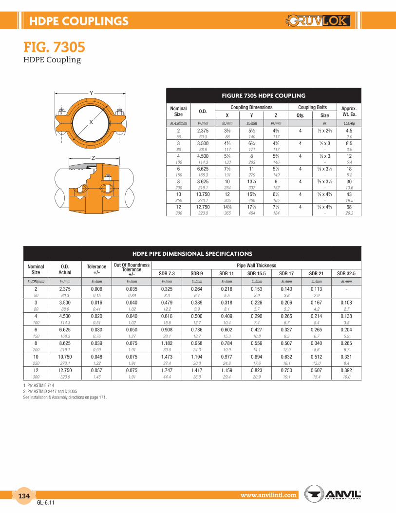
HdPE couPLInGS
www.anvilintl.com134
fiG. 7305HDPE Coupling
1. Per ASTM F 7142. Per ASTM D 2447 and D 3035See Installation & Assembly directions on page 171.
FIGurE 7305 HdPE couPLInG
Nominal Size O.D.
Coupling Dimensions Coupling Bolts Approx. Wt. Ea.X Y Z Qty. Size
In./DN(mm) In./mm In./mm In./mm In./mm In. Lbs./Kg
2 2.375 33⁄8 51⁄2 45⁄8 4 1⁄2 x 23⁄8 4.550 60.3 86 140 117 - 2.0
3 3.500 45⁄8 63⁄4 45⁄8 4 1⁄2 x 3 8.580 88.9 117 171 117 - 3.9
4 4.500 51⁄4 8 53⁄4 4 1⁄2 x 3 12100 114.3 133 203 146 - 5.4
6 6.625 71⁄2 11 57⁄8 4 5⁄8 x 31⁄2 18150 168.3 191 279 149 - 8.2
8 8.625 10 131⁄4 6 4 5⁄8 x 31⁄2 30200 219.1 254 337 152 - 13.6
10 10.750 12 153⁄4 61⁄2 4 3⁄4 x 43⁄4 43250 273.1 305 400 165 - 19.5
12 12.750 143⁄8 177⁄8 71⁄4 4 3⁄4 x 43⁄4 58300 323.9 365 454 184 - 26.3
HdPE PIPE dIMEnSIonAL SPEcIFIcAtIonS
Nominal Size
O.D.Actual
Tolerance +/-
Out Of Roundness Tolerance
+/-
Pipe Wall Thickness
SDR 7.3 SDR 9 SDR 11 SDR 15.5 SDR 17 SDR 21 SDR 32.5In./DN(mm) In./mm In./mm In./mm In./mm In./mm In./mm In./mm In./mm In./mm In./mm
2 2.375 0.006 0.035 0.325 0.264 0.216 0.153 0.140 0.113 -50 60.3 0.15 0.89 8.3 6.7 5.5 3.9 3.6 2.9
3 3.500 0.016 0.040 0.479 0.389 0.318 0.226 0.206 0.167 0.10880 88.9 0.41 1.02 12.2 9.9 8.1 5.7 5.2 4.2 2.7
4 4.500 0.020 0.040 0.616 0.500 0.409 0.290 0.265 0.214 0.138100 114.3 0.51 1.02 15.6 12.7 10.4 7.4 6.7 5.4 3.5
6 6.625 0.030 0.050 0.908 0.736 0.602 0.427 0.327 0.265 0.204150 168.3 0.76 1.27 23.1 18.7 15.3 10.8 8.3 6.7 5.2
8 8.625 0.039 0.075 1.182 0.958 0.784 0.556 0.507 0.340 0.265200 219.1 0.99 1.91 30.0 24.3 19.9 14.1 12.9 8.6 6.7
10 10.750 0.048 0.075 1.473 1.194 0.977 0.694 0.632 0.512 0.331250 273.1 1.22 1.91 37.4 30.3 24.8 17.6 16.1 13.0 8.4
12 12.750 0.057 0.075 1.747 1.417 1.159 0.823 0.750 0.607 0.392300 323.9 1.45 1.91 44.4 36.0 29.4 20.9 19.1 15.4 10.0
Z
Y
X
GL-6.11

hdpe couplings
Intro
duct
ion
Coup
lings
Outle
tsFi
tting
sVa
lves
&
Acce
ssor
ies
High
Pres
sure
DI-L
OK®
Nipp
les
Plai
n-En
dFi
tting
sHD
PECo
uplin
gsSo
ck-It
®
Fitti
ngs
Stai
nles
sSt
eel M
etho
dRo
ll Gr
oove
rsIn
stal
latio
n&
Ass
embl
ySp
ecia
lCo
atin
gsDe
sign
Serv
ices
Tech
nica
lDa
taM
aste
r For
mat
3 Pa
rt Sp
ecs.
Pict
oria
lIn
dex
CTS
Copp
er
Syst
em
www.anvilintl.com 135
FIG. 7307HDPE Transition Coupling
materIal specIFIcatIons
HOUSING: Ductile Iron conforming to ASTM A 536, Grade 65-45-12
COATING: Rust inhibiting paint – Color: Orange Other Colors Available (IE: RAL3000 and RAL9000) For other Coating requirements contact an Anvil Representative.
ANSI BOLTS & HEAVY HEX NUTS: Heat treated, zinc electroplated, carbon steel oval-neck track bolts conforming to ASTM A 183. Zinc electroplated carbon steel heavy hex nuts conforming to ASTM A 563 Grade A or Grade B, or J995 Grade 2.
GASKETS: Properties in accordance with ASTM D 2000Grade E EPDM (Green color code)
Service Temperature Range: -30°F to 230°F (-34°C to 110°C). Recommended for water service, dilute acids, alkaline solutions, oil free air and many chemical services. NOT FOR USE IN PETROLEUM APPLICATIONS.
Grade T Nitrile (Orange color code) Service Temperature Range: -20°F to 180°F (-29°C to 82°C). Recommended for petroleum applications, air with oil vapor, vegetable and mineral oils. NOT FOR USE WITH HOT WATER OR HOT AIR.
For specific chemical applications, reference the Gruvlok Gasket Recommendations section of the Gruvlok catalog.
WARning:
1. Gruvlok products for HDPE pipe must be installed using Gruvlok XtremeTM Temperature Lubricant.
2. The gasket temperature rating may exceed the manufacturer temperature rating for the HDPE pipe. Consult the HDPE pipe manufacturer for the temperature and pressure ratings.
The Gruvlok Figure 7307 HDPE transition coupling allows for transition from HDPE pipe or fittings to grooved-end pipe prepared per Gruvlok standard cut or roll groove specifications for steel pipe or Gruvlok fittings. The Figure 7307 incorporates two banks of machined teeth on one side of the housing, and a key section on the other, that engages specifically grooved steel pipe or fittings. The banks of teeth are positioned away from the gasket enhancing the sealing ability of the gasket. The temperature and pressure capabilities of the Figure 7307 exceed the highest temperature and pressure ratings of the HDPE pipe.
The Figure 7307 features a low profile contoured housing with a ramp along the outside diameter on the half of the HDPE coupling. This easy to assemble mechanical joint is used to join HDPE pipe (conforming to ASTM D 2447, D 3000, D 3035, or F 714) to roll grooved or cut grooved standard weight and, roll grooved lightweight pipe, as well as with grooved-end fittings and valves. The coupling can be used with HDPE pipe having SDR values of 7.3 to 32.5.
GL-7.12

HdPE couPLInGS
www.anvilintl.com136
fiG. 7307HDPE Transition Coupling
1. Per ASTM F 7142. Per ASTM D 2447 and D 30353. For steel pipe requirements refer to Gruvlok Groove Specifications for steel pipe.See Installation & Assembly directions on page 172.
FIGurE 7307 HdPE trAnSItIon couPLInG
Nominal Size
O.D. Actual
Coupling Dimensions Coupling Bolts Approx. Wt. Ea.X Y Z Qty. Size
In./DN(mm) In./mm In./mm In./mm In./mm In./mm Lbs./Kg
2 2.375 33⁄8 6 31⁄8 4 1⁄2 x 23⁄8 4.550 60.3 86 152 79 - 2.0
3 3.500 41⁄2 71⁄8 31⁄8 4 1⁄2 x 3 680 88.9 114 181 79 - 2.7
4 4.500 53⁄4 81⁄2 33⁄4 4 1⁄2 x 3 8.5100 114.3 146 216 95 - 3.9
6 6.625 8 111⁄4 33⁄4 4 5⁄8 x 31⁄2 12.5150 168.3 203 286 95 - 5.7
8 8.625 101⁄2 135⁄8 41⁄4 4 5⁄8 x 31⁄2 20.5200 219.1 267 346 108 - 9.3
10 10.750 125⁄8 17 5 4 7⁄8 x 51⁄2 34.5250 273.1 321 432 127 - 15.6
12 12.750 143⁄4 191⁄2 5 4 7⁄8 x 51⁄2 42.5300 323.9 375 495 127 - 19.3
HdPE PIPE dIMEnSIonAL SPEcIFIcAtIonS
Nominal Size
O.D. Actual
Tolerance+/-
Out of Roundness Tolerance
+/-
Pipe Wall Thickness
SDR 7.3 SDR 9 SDR 11 SDR 15.5 SDR 17 SDR 21 SDR 32.5In./DN(mm) In./mm In./mm In./mm In./mm In./mm In./mm In./mm In./mm In./mm In./mm
2 2.375 0.006 0.035 0.325 0.264 0.216 0.153 0.140 0.113 -50 60.3 0.15 0.89 8.3 6.7 5.5 3.9 3.6 2.9
3 3.500 0.016 0.040 0.479 0.389 0.318 0.226 0.206 0.167 0.10880 88.9 0.41 1.02 12.2 9.9 8.1 5.7 5.2 4.2 2.7
4 4.500 0.020 0.040 0.616 0.500 0.409 0.290 0.265 0.214 0.138100 114.3 0.51 1.02 15.6 12.7 10.4 7.4 6.7 5.4 3.5
6 6.625 0.030 0.050 0.908 0.736 0.602 0.427 0.327 0.265 0.204150 168.3 0.76 1.27 23.1 18.7 15.3 10.8 8.3 6.7 5.2
8 8.625 0.039 0.075 1.182 0.958 0.784 0.556 0.507 0.340 0.265200 219.1 0.99 1.91 30.0 24.3 19.9 14.1 12.9 8.6 6.7
10 10.750 0.048 0.075 1.473 1.194 0.977 0.694 0.632 0.512 0.331250 273.1 1.22 1.91 37.4 30.3 24.8 17.6 16.1 13.0 8.4
12 12.750 0.057 0.075 1.747 1.417 1.159 0.823 0.750 0.607 0.392300 323.9 1.45 1.91 44.4 36.0 29.4 20.9 19.1 15.4 10.0
X
Y
Z
GL-6.11

hdpe couplings
Intro
duct
ion
Coup
lings
Outle
tsFi
tting
sVa
lves
&
Acce
ssor
ies
High
Pres
sure
DI-L
OK®
Nipp
les
Plai
n-En
dFi
tting
sHD
PECo
uplin
gsSo
ck-It
®
Fitti
ngs
Stai
nles
sSt
eel M
etho
dRo
ll Gr
oove
rsIn
stal
latio
n&
Ass
embl
ySp
ecia
lCo
atin
gsDe
sign
Serv
ices
Tech
nica
lDa
taM
aste
r For
mat
3 Pa
rt Sp
ecs.
Pict
oria
lIn
dex
CTS
Copp
er
Syst
em
www.anvilintl.com 137
FIG. 7312HDPE Flange Adapter
The Gruvlok® Figure 7312 forms a cost-effective, easy-to-assemble mechanical joint between HDPE (high density polyethylene) pipe and fittings and ANSI Class 125 or Class 150 piping components without the need for costly fusion equipment. The flanged couplings are designed for wall thickness’ SDR 32.5 to 7.3 HDPE pipe and fittings conforming to ASTM D 2447, D 3000, D 3035, or F 174. Each coupling uses two bolts to drive the sharply machined housing teeth into the outside of the pipe. The teeth are arranged in two banks, each bank consisting of at least three rows of spiral teeth that effectively grip the pipe, providing a secure mechanical joint with pressure capabilities exceeding that of the HDPE pipe itself. The banks of teeth are positioned away from the gasket, enhancing the sealing ability of the gaskets throughout the entire operating temperature range.
materIal specIFIcatIonsHOUSING: Ductile Iron conforming to ASTM A 536, Grade 65-45-12
COATING: Rust inhibiting paint – Color: Orange Other Colors Available (IE: RAL3000 and RAL9000) For other Coating requirements contact an Anvil Representative.
ANSI BOLTS & HEAVY HEX NUTS: Heat treated, zinc electroplated, carbon steel oval-neck track bolts conforming to ASTM A 183. Zinc electroplated heavy hex nuts of carbon steel conforming to ASTM A 563 Grade A or Grade B, or J995 Grade 2.
GASKETS: Properties in accordance with ASTM D 2000
Grade E EPDM (Green color code) Service Temperature Range: -30°F to 230°F (-34°C to 110°C). Recommended for water service, dilute acids, alkaline solutions, oil free air and many chemical services. NOT FOR USE IN PETROLEUM APPLICATIONS.
Grade T Nitrile (Orange color code) Service Temperature Range: -20°F to 180°F (-29°C to 82°C). Recommended for petroleum applications, air with oil vapor, vegetable and mineral oils. NOT FOR USE WITH HOT WATER OR HOT AIR.
For specific chemical applications, reference the Gruvlok Gasket Recommendations section of the Gruvlok catalog.
GL-7.12
WARning:
1. Gruvlok products for HDPE pipe must be installed using Gruvlok XtremeTM Temperature Lubricant.
2. The gasket temperature rating may exceed the manufacturer temperature rating for the HDPE pipe. Consult the HDPE pipe manufacturer for the temperature and pressure ratings.
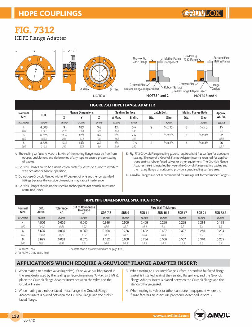
HdPE couPLInGS
www.anvilintl.com138
fiG. 7312HDPE Flange Adapter
1. When mating to a wafer valve (lug valve), if the valve is rubber faced in the area designated by the sealing surface dimensions (A Max. to B Min.), place the Gruvlok Flange Adapter Insert between the valve and the Gruvlok Flange.
2. When mating to a rubber-faced metal flange, the Gruvlok Flange Adapter Insert is placed between the Gruvlok Flange and the rubber-faced flange.
3. When mating to a serrated flange surface, a standard fullfaced flange gasket is installed against the serrated flange face, and the Gruvlok Flange Adapter Insert is placed between the Gruvlok Flange and the standard flange gasket.
4. When mating to valves or other component equipment where the flange face has an insert, use procedure described in note 3.
applications which reQuire a Gruvlok® flanGe adapter insert:
A. The sealing surfaces A Max. to B Min. of the mating flange must be free from gouges, undulations and deformities of any type to ensure proper sealing of gasket.
B. Gruvlok Flanges are to be assembled on butterfly valves so as not to interfere with actuator or handle operation.
C. Do not use Gruvlok Flanges within 90 degrees of one another on standard fittings because the outside dimensions may cause interference.
D. Gruvlok Flanges should not be used as anchor points for tierods across non-restrained joints.
E. Fig. 7312 Gruvlok Flange sealing gaskets require a hard flat surface for adequate sealing. The use of a Gruvlok Flange Adapter Insert is required for applica-tions against rubber faced valves or other equipment. The Gruvlok Flange Adapter Insert is installed between the Gruvlok Flange sealing gasket and the mating flange or surface to provide a good sealing surface area.
F. Gruvlok Flanges are not recommended for use against formed rubber flanges.
1. Per ASTM F 714 See Installation & Assembly directions on page 173.2. Per ASTM D 2447 and D 3035
FIGurE 7312 HdPE FLAnGE AdAPtEr
Nominal Size O.D.
Flange Dimensions Sealing Surface Latch Bolt Mating Flange Bolts Approx. Wt. Ea.X Y Z A Max. B Min. Qty. Size Qty. Size
In./DN(mm) In./mm In./mm In./mm In./mm In./mm In./mm In./mm In./mm Lbs./Kg
4 4.500 9 103⁄8 31⁄8 41⁄2 53⁄4 2 5⁄8 x 15⁄8 8 5⁄8 x 3 15100 114.3 229 264 79 114 146 6.8
6 6.625 111⁄4 123⁄8 37⁄8 65⁄8 73⁄4 2 5⁄8 x 23⁄8 8 3⁄4 x 31⁄2 22150 168.3 286 314 98 168 197 10.0
8 8.625 131⁄2 147⁄8 31⁄2 85⁄8 101⁄4 2 3⁄4 x 23⁄4 8 3⁄4 x 31⁄2 26200 219.1 343 378 89 219 260 12.7
HdPE PIPE dIMEnSIonAL SPEcIFIcAtIonS
Nominal Size
O.D. Actual
Tolerance +/-
Out of Roundness Tolerance
+/-
Pipe Wall Thickness
SDR 7.3 SDR 9 SDR 11 SDR 15.5 SDR 17 SDR 21 SDR 32.5In./DN(mm) In./mm In./mm In./mm In./mm In./mm In./mm In./mm In./mm In./mm In./mm
4 4.500 0.020 0.040 0.616 0.500 0.409 0.290 0.265 0.214 0.138100 114.3 0.51 1.02 15.6 12.7 10.4 7.4 6.7 5.4 3.5
6 6.625 0.030 0.050 0.908 0.736 0.602 0.427 0.327 0.265 0.204150 168.3 0.76 1.27 23.1 18.7 15.3 10.8 8.3 6.7 5.2
8 8.625 0.039 0.075 1.182 0.958 0.784 0.556 0.507 0.340 0.265200 219.1 0.99 1.91 30.0 24.3 19.9 14.1 12.9 8.6 6.7
Y Z
X
Gruvlok Fig.7312 Flange
Gruvlok Fig.7312 Flange
Serrated FaceMating Flange
FlangeGasket
Mating FlangeComponent
Grooved Pipe Grooved PipeRubber SurfaceGruvlok Flange Adapter Insert
Gruvlok Flange Adapter InsertB min.A max.
NOTE A NOTES 1 and 2 NOTES 3 and 4
GL-7.12

SocK-It® PIPInG MEtHod
Intro
duct
ion
Coup
lings
Outle
tsFi
tting
sVa
lves
&
Acce
ssor
ies
High
Pres
sure
DI-L
OK®
Nipp
les
Plai
n-En
dFi
tting
sHD
PECo
uplin
gsSo
ck-It
®
Fitti
ngs
Stai
nles
sSt
eel M
etho
dRo
ll Gr
oove
rsIn
stal
latio
n&
Ass
embl
ySp
ecia
lCo
atin
gsDe
sign
Serv
ices
Tech
nica
lDa
taM
aste
r For
mat
3 Pa
rt Sp
ecs.
Pict
oria
lIn
dex
CTS
Copp
er
Syst
em
www.anvilintl.com 139
Nominal Size O.D.
In./DN(mm) In./mm
1⁄2 0.84015 21.33⁄4 1.05020 26.7
1 1.31525 33.7
11⁄4 1.66032 42.4
Nominal Size O.D.
In./DN(mm) In./mm
11⁄2 1.90040 48.3
2 2.37550 60.3
21⁄2 2.87565 73.0
FIttInG SIZE
sock-it® pipinG method fittinGs
The Gruvlok® Sock-It® Piping Method provides a quick, secure and reliable method of joining plain-end steel pipe. Several Sock-It configurations are available: tees with NPT outlets, reducing run tees with NPT outlets, straight couplings, 90 elbows, straight tees and reducing elbows. Pressure energized elastomeric gaskets provide the Sock-It with a leak tight seal. Specially designed lock bolts secure the pipe in the Sock-It Fitting, providing a fast, dependable way of joining small diameter plain-end pipe.
Working pressure ratings shown are for reference only and are based on schedule 40 pipe. For the latest UL/ULC Listed and FM approved pressure ratings versus pipe schedule see www.anvilintl.com or contact your local Anvil Sales Representative.
See Installation & Assembly directions on page 174.
fiG. 7100 - 90° Elbow (Sock-It® x Sock-It®)
material specificationsHOUSING: Cast iron ASTM A 126 CLASS A
BOLTS: Case hardened carbon steel, dichromate finish.
GASKETS: EPDM, as specified in accordance with ASTM D 2000
NOTE: All Sock-It® fittings are UL/ULC Listed and FM Approved for 175 psi working pressure when used to join XL Pipe and Dyna-Flow Pipe.
The Fitting Size Chart is used to determine the O.D. of the pipe that the fittings is to be used with. Gruvlok Fittings are identified by either the Nominal size in inches or the Pipe O.D. in mm.
* “U” - Run take-out dimension.
FIGurE 7100 SocK-It® ELBoW (S X S)
Nominal Size O.D.
Max. Working Pressure Dimensions Approx. Wt. Ea.UL/ULC Listed FM Approved Center To End U* W Y
In./DN(mm) In./mm PSI/bar PSI/bar In./mm In./mm In./mm In./mm Lbs./Kg
1 1.315 300 300 25⁄16 7⁄8 11⁄16 13⁄4 1.925 33.7 20.7 20.7 59 22 27 44 0.911⁄4 1.660 300 300 27⁄16 1 11⁄4 113⁄16 2.332 42.4 20.7 20.7 62 25 32 46 1.011⁄2 1.900 300 300 25⁄8 11⁄8 13⁄8 115⁄16 2.740 48.3 20.7 20.7 67 29 35 49 1.22 2.375 175 250 31⁄4 19⁄16 15⁄8 23⁄16 4.050 60.3 12.1 17.2 83 40 41 56 1.8
W YC to E
U
GL-7.12
For Listings/Approval Details and Limitations,visit our website at www.anvilintl.com orcontact an Anvil® Sales Representative.

SocK-It® PIPInG MEtHod
www.anvilintl.com140
sock-it® pipinG method fittinGs
fiG. 7101 - 90° Reducing Elbow (Sock-It® x NPT)
fiG. 7103 - Straight Tee (Sock-It® x Sock-It® x Sock-It®)
C to SE - Center to Sock-It® End * “U” - Take-out dimension, Sock-It® End.C to TE - Center to Thread End ** “T” - Take-out dimension, Thread End.
* “U” - Run take-out dimension.**“T” - Outlet take-out dimension.
FIGurE 7103 SocK-It® StrAIGHt tEE (S x S x S)
Nominal Size O.D.
Max. Working Pressure Dimensions Approx. Wt. Ea.UL/ULC Listed FM Approved **T U* V W Y Z
In./DN(mm) In./mm PSI/bar PSI/bar In./mm In./mm In./mm In./mm In./mm In./mm Lbs./Kg
1 1.315 300 300 13⁄16 15⁄8 21⁄4 11⁄16 111⁄16 41⁄2 2.325 33.7 20.7 20.7 21 41 57 27 43 114 1.011⁄4 1.660 175 300 1 2 27⁄16 11⁄4 113⁄16 47⁄8 2.932 42.4 12.1 20.7 25 51 62 32 46 124 1.311⁄2 1.900 175 300 11⁄16 21⁄8 29⁄16 13⁄8 115⁄16 51⁄8 3.440 48.3 12.1 20.7 17 54 65 35 49 130 1.52 2.375 175 250 15⁄16 25⁄8 3 111⁄16 23⁄16 6 5.650 60.3 12.1 17.2 23 67 76 43 56 152 2.5
FIGurE 7101 SocK-It® rEducInG ELBoW (S X nPt)
Nominal Size
Max. Working Pressure Dimensions Approx. Wt. Ea.UL/ULC Listed FM Approved Center to TE Center To SE U* T** W Y
In./DN(mm) PSI/bar PSI/bar In./mm In./mm In./mm In./mm In./mm In./mm Lbs./Kg
1 x 1⁄2 300 300 17⁄16 25⁄16 7⁄8 1 11⁄16 111⁄16 1.725 x 15 20.7 20.7 37 59 22 25 27 43 0.81 x 3⁄4 300 300 17⁄16 25⁄16 7⁄8 7⁄8 11⁄16 111⁄16 1.625 x 20 20.7 20.7 37 59 22 22 27 43 0.71 x 1 300 300 17⁄16 25⁄16 7⁄8 7⁄8 11⁄16 111⁄16 1.5
25 x 25 20.7 20.7 37 59 22 22 27 43 0.711⁄4 x 1⁄2 300 300 19⁄16 21⁄2 11⁄16 11⁄8 11⁄4 113⁄16 2.232 x 15 20.7 20.7 40 64 17 29 32 46 1.011⁄4 x 3⁄4 300 300 19⁄16 21⁄2 11⁄16 1 11⁄4 113⁄16 2.132 x 20 20.7 20.7 40 64 17 25 32 46 1.011⁄4 x 1 300 300 19⁄16 21⁄2 11⁄16 1 11⁄4 113⁄16 232 x 25 20.7 20.7 40 64 17 25 32 46 0.911⁄2 x 1⁄2 300 300 111⁄16 21⁄2 1 11⁄4 13⁄8 115⁄16 2.540 x 15 20.7 20.7 43 64 25 32 35 49 1.111⁄2 x 3⁄4 300 300 111⁄16 21⁄2 1 11⁄8 13⁄8 115⁄16 2.440 x 20 20.7 20.7 43 64 25 29 35 49 1.111⁄2 x 1 300 300 111⁄16 21⁄2 1 11⁄8 13⁄8 115⁄16 2.340 x 25 20.7 20.7 43 64 25 29 35 49 1.0
YW
U
T
C to SE
C to TE
Z
U
Y
V
T
W
fiG. 7107 - Coupling (Sock-It® x Sock-It®)
* “U” - Run take-out dimension.
FIGurE 7107 SocK-It® couPLInG (S x S)
Nominal Size O.D.
Max. Working Pressure Dimensions Approx. Wt. Ea.UL/ULC Listed FM Approved U* W Y Z
In./DN(mm) In./mm PSI/bar PSI/bar In./mm In./mm In./mm In./mm Lbs./Kg
1 1.315 300 300 1⁄4 11⁄16 111⁄16 31⁄8 1.725 33.7 20.7 20.7 6 27 43 79 0.811⁄4 1.660 300 300 1⁄4 11⁄4 113⁄16 31⁄8 1.932 42.4 20.7 20.7 6 32 46 79 0.911⁄2 1.900 300 300 1⁄4 13⁄8 115⁄16 31⁄4 2.140 48.3 20.7 20.7 6 35 49 83 1.02 2.375 175 250 1⁄4 15⁄8 23⁄16 35⁄8 2.950 60.3 12.1 17.2 6 41 56 92 1.3
Y
W
Z
U
GL-6.11

SocK-It® PIPInG MEtHod
Intro
duct
ion
Coup
lings
Outle
tsFi
tting
sVa
lves
&
Acce
ssor
ies
High
Pres
sure
DI-L
OK®
Nipp
les
Plai
n-En
dFi
tting
sHD
PECo
uplin
gsSo
ck-It
®
Fitti
ngs
Stai
nles
sSt
eel M
etho
dRo
ll Gr
oove
rsIn
stal
latio
n&
Ass
embl
ySp
ecia
lCo
atin
gsDe
sign
Serv
ices
Tech
nica
lDa
taM
aste
r For
mat
3 Pa
rt Sp
ecs.
Pict
oria
lIn
dex
CTS
Copp
er
Syst
em
www.anvilintl.com 141
sock-it® pipinG method fittinGs
fiG. 7105 - Reducing Outlet Tee (Sock-It® x Sock-It® x NPT)
fiG. 7106 - Reducing Tee (Sock-It® x Sock-It® x NPT)
* “U” - Run take-out dimension. ** “T” - Outlet take-out dimension.
* “U” - Run take-out dimension. ** “T” - Outlet take-out dimension.
FIGurE 7105 SocK-It® rEducInG outLEt tEE (S X S X nPt)
Nominal Size
Max. Working Pressure Dimensions Approx. Wt. Ea.UL/ULC Listed FM Approved **T U* V W Y Z
In./DN(mm) PSI/bar PSI/bar In./mm In./mm In./mm In./mm In./mm In./mm Lbs./Kg
1 x 1 x 1⁄2 300 300 1 13⁄8 17⁄16 11⁄16 111⁄16 41⁄4 2.025 x 25 x 15 20.7 20.7 25 35 37 27 43 108 0.9
1 x 1 x 3⁄4 300 300 7⁄8 13⁄8 17⁄16 11⁄16 111⁄16 41⁄4 1.925 x 25 x 20 20.7 20.7 22 35 37 27 43 108 0.9
1 x 1 x 1 300 300 7⁄8 13⁄8 17⁄16 11⁄16 111⁄16 41⁄4 1.925 x 25 x 25 20.7 20.7 22 35 37 27 43 108 0.9
11⁄4 x 11⁄4 x 1⁄2 300 300 11⁄8 13⁄8 15⁄8 11⁄4 113⁄16 41⁄4 2.232 x 32 x 15 20.7 20.7 29 35 41 32 46 108 1.0
11⁄4 x 11⁄4 x 3⁄4 300 300 1 13⁄8 15⁄8 11⁄4 113⁄16 41⁄4 2.232 x 32 x 20 20.7 20.7 25 35 41 32 46 108 1.0
11⁄4 x 11⁄4 x 1 300 300 1 13⁄8 15⁄8 11⁄4 113⁄16 41⁄4 2.032 x 32 x 25 20.7 20.7 25 35 41 32 46 108 0.9
11⁄2 x 11⁄2 x 1⁄2 300 300 11⁄4 13⁄8 13⁄4 13⁄8 115⁄16 43⁄8 2.740 x 40 x 15 20.7 20.7 32 35 44 35 49 111 1.2
11⁄2 x 11⁄2 x 3⁄4 300 300 11⁄8 13⁄8 13⁄4 13⁄8 115⁄16 43⁄8 2.640 x 40 x 20 20.7 20.7 29 35 44 35 49 111 1.2
11⁄2 x 11⁄2 x 1 300 300 11⁄8 13⁄8 13⁄4 13⁄8 115⁄16 43⁄8 2.540 x 40 x 25 20.7 20.7 29 35 44 35 49 111 1.1
2 x 2 x 1⁄2 175 250 11⁄2 13⁄8 115⁄16 15⁄8 23⁄16 43⁄4 3.550 x 50 x 15 12.1 17.2 38 35 49 41 56 121 1.6
2 x 2 x 3⁄4 175 250 13⁄8 13⁄8 115⁄16 15⁄8 23⁄16 43⁄4 3.450 x 50 x 20 12.1 17.2 35 35 49 41 56 121 1.5
2 x 2 x 1 175 250 13⁄8 13⁄8 115⁄16 15⁄8 23⁄16 43⁄4 3.350 x 50 x 25 12.1 17.2 35 35 49 41 56 121 1.5
21⁄2 x 21⁄2 x 3⁄4 175 175 11⁄2 13⁄8 21⁄8 115⁄16 27⁄16 43⁄4 5.265 x 65 x 20 12.1 12.1 38 35 54 49 62 121 2.4
21⁄2 x 21⁄2 x 1 175 175 11⁄2 13⁄8 21⁄8 115⁄16 27⁄16 43⁄4 5.265 x 65 x 25 12.1 12.1 38 35 54 49 62 121 2.4
FIGurE 7106 SocK-It® rEducInG tEE (S x S x nPt)
Nominal SizeMax. Working Pressure Dimensions Approx.
Wt. Ea.UL/ULC Listed FM Approved **T U* V W Y ZIn./DN(mm) PSI/bar PSI/bar In./mm In./mm In./mm In./mm In./mm In./mm Lbs./Kg
11⁄4 x 1 x 1⁄2 300 300 1 13⁄8 17⁄16 11⁄4 113⁄16 41⁄4 2.132 x 25 x 15 2.1 2.1 25 35 37 32 46 108 1.011⁄4 x 1 x 3⁄4 300 300 7⁄8 13⁄8 17⁄16 11⁄4 113⁄16 41⁄4 2.132 x 25 x 20 20.7 20.7 22 35 37 32 46 108 1.011⁄4 x 1 x 1 300 300 7⁄8 13⁄8 17⁄16 11⁄4 113⁄16 41⁄4 2.032 x 25 x 25 20.7 20.7 22 35 37 32 46 108 0.9
11⁄2 x 11⁄4 x 1⁄2 300 300 11⁄8 13⁄8 19⁄16 13⁄8 115⁄16 43⁄8 2.540 x 32 x 15 20.7 20.7 29 35 40 35 49 111 1.1
11⁄2 x 11⁄4 x 3⁄4 300 300 1 13⁄8 19⁄16 13⁄8 115⁄16 43⁄8 2.440 x 32 x 20 20.7 20.7 25 35 40 35 49 111 1.1
11⁄2 x 11⁄4 x 1 300 300 1 13⁄8 19⁄16 13⁄8 115⁄16 43⁄8 2.240 x 32 x 25 20.7 20.7 25 35 40 35 49 111 1.02 x 11⁄2 x 1⁄2 175 250 11⁄4 13⁄8 13⁄4 15⁄8 23⁄16 49⁄16 3.250 x 40 x 15 12.1 17.2 32 35 44 41 56 116 1.52 x 11⁄2 x 3⁄4 175 250 11⁄8 13⁄8 13⁄4 15⁄8 23⁄16 49⁄16 3.150 x 40 x 20 12.1 17.2 29 35 44 41 56 116 1.42 x 11⁄2 x 1 175 250 11⁄8 13⁄8 13⁄4 15⁄8 23⁄16 49⁄16 3.050 x 40 x 25 12.1 17.2 29 35 44 41 56 116 1.4
Y
V T
W
Z
U
Z
U
Y
V T
W
GL-6.11

stainless steel method
www.anvilintl.com142
FIG. 7400SSRigidlite® Coupling
The Gruvlok Figure 7400SS coupling is available in 1 1⁄4" – 8" sizes. The standard material is ASTM A 743 CF8M (Type 316) cast stainless steel which is ideal for corrosive environments.
Any Gruvlok gasket material may be utilized in the 7400SS coupling for a broad array of applications. Gasket properties are as designated in accordance with ASTM D 2000. The 7400SS is provided with ASTM A 193 B8M bolts and ASTM A 194 Grade 8M nuts.
MATERIAL SPECIFICATIONSSTAINLESS STEEL BOLTS & NUTS: Hex head stainless steel bolts, Type 316 per ASTM A 193 Grade B8M class 1 and heavy hex stainless steel nuts, Type 316 per ASTM A 194 Grade 8M class 1. Nuts and bolts are zinc plated to prevent common thread galling. Contact an Anvil Representative for more information.
HOUSING: Cast Stainless Steel (Type 316) - ASTM A 743 CF8M
GASKETS: Materials Properties as designated in accordance with ASTM D 2000
Grade “E” EPDM (Green color code) NSF 61 Certified -40°F to 230°F (Service Temperature Range)(-40°C to 110°C) Recommended for water service, diluted acids, alkalies solutions, oil-free air and many chemical services. NOT FOR USE IN PETROLEUM APPLICATIONS.
Grade “T” Nitrile (Orange color code) -20°F to 180°F (Service Temperature Range)(-29°C to 82°C) Recommended for petroleum applications. air with oil vapors and vegetable and mineral oils. NOT FOR USE IN HOT WATER OR HOT AIR.
Grade “O” Fluoro-Elastomer (Blue color code) 20°F to 300°F (Service Temperature Range)(-29°C to 149°C) Recommended for high temperature resistance to oxidizing acids, petroleum oils, hydraulic fluids, halogenated hydrocarbons and lubricants.
Grade “L” Silicone (Red color code) -40°F to 350°F (Service Temperature Range)(-40°C to 177°C) Recommended for dry, hot air and some high temperature chemical services.
GASKET TYPE: Standard C Style Flush Gap (1 1⁄4" – 8")
LUBRICATION: Standard Gruvlok Gruvlok XtremeTM (Do Not use with Grade “L”)
* All bolts are hex head design Type 316 Grade B8M Class 1 stainless steel to ASTM A 193, with Type 316 Grade 8M stainless steel heavy hex nuts conforming to ASTM A 194. Use of suitable anti-galling thread compound is recommended.
† Ratings apply when used with Schedule 40 ASTM A 312 Type 304 stainless steel pipe for all sizes. Refer to ratings chart for additional data.
FiGURe 7400ss - RiGidlite stainless steel CoUPlinG
Nominal Size O.D.
Max. Wk.
Pressure†
Max. End
Load†
Range of Pipe End
Separation
Coupling Dimensions Coupling Bolts* Specified Torque
Approx. Wt. Ea.X Y Z Qty. Size
Min. Max.In./mm In./mm PSI/bar Lbs./kN In./mm In./mm In./mm In./mm In./mm Ft.-Lbs./N-m Lbs./Kg
11⁄4 1.660 300 649 0-1⁄32 27⁄8 41⁄8 13⁄4 2 3⁄8 x 21⁄4 15 20 1.632 42.4 20.7 2.89 0-0.79 73 105 44 M10 x 57 21 27 0.7
11⁄2 1.900 300 851 0-1⁄32 31⁄8 45⁄8 13⁄4 2 3⁄8 x 21⁄4 15 20 1.740 48.3 20.7 3.78 0-0.79 79 117 44 M10 x 57 21 27 0.8
2 2.375 300 1,329 0-1⁄32 35⁄8 53⁄8 13⁄4 2 3⁄8 x 21⁄4 15 20 2.150 60.3 20.7 5.91 0-0.79 92 137 45 M10 x 57 21 27 1.0
21⁄2 2.875 300 1,948 0-1⁄32 41⁄8 57⁄8 13⁄4 2 3⁄8 x 21⁄4 15 20 2.365 73.0 20.7 8.66 0-0.79 105 149 44 M10 x 57 21 27 1.0
3 3.500 300 2,886 0-1⁄32 45⁄8 65⁄8 13⁄4 2 1⁄2 x 23⁄4 50 60 3.180 88.9 20.7 12.84 0-0.79 117 168 44 M12 x 70 68 80 1.4
4 4.500 300 4,771 0-3⁄32 6 73⁄4 17⁄8 2 1⁄2 x 23⁄4 50 60 4.4100 114.3 20.7 21.22 0-2.38 152 197 48 M12 x 70 68 80 2.0
6 6.625 275 9,480 0-3⁄32 81⁄8 111⁄8 2 2 3/4 x 3 80 100 7.8150 168.3 19.0 42.17 0-2.38 206 283 51 M20 x 76 110 150 3.5
8 8.625 275 16,067 0-3⁄32 103⁄8 135⁄8 23⁄8 2 3/4 x 3 80 100 13.2200 219.1 19.0 71.47 0-2.38 264 346 60 M20 x 76 110 150 6.0
Range of Pipe End Separation values are for roll grooved pipe and may be doubled for cut groove pipe.
Y Z
X
CAUTION: Contact your local Anvil representative for corrosiveapplication environments.
No coatings or zinc options.
GL-7.12

StAInLESS StEEL MEtHod
Intro
duct
ion
Coup
lings
Outle
tsFi
tting
sVa
lves
&
Acce
ssor
ies
High
Pres
sure
DI-L
OK®
Nipp
les
Plai
n-En
dFi
tting
sHD
PECo
uplin
gsSo
ck-It
®
Fitti
ngs
Stai
nles
sSt
eel M
etho
dRo
ll Gr
oove
rsIn
stal
latio
n&
Ass
embl
ySp
ecia
lCo
atin
gsDe
sign
Serv
ices
Tech
nica
lDa
taM
aste
r For
mat
3 Pa
rt Sp
ecs.
Pict
oria
lIn
dex
CTS
Copp
er
Syst
em
www.anvilintl.com 143
Gruvlok stainless steel fittinGsAnvil offers two different sets of stainless steel fittings. The Gruvlok Series Fittings have full flow designs formed from type 304SS pipe. The Schedule 10 fittings are fabricated from segmentally welded 316SS unless otherwise noted and are also available as Schedule 40 and/or Type 304SS.
GruVLoK couPLInG & FLAnGE WorKInG PrESSurE rAtInGS (PSI)on 304 And 316 StAInLESS StEEL roLL GrooVEd PIPE
Nominal Pipe Size
PipeO.D.
NominalWall
Thickness
PipeScheduleNumber
Coupling and Flanges
Fig. 7000Lightweight
Fig. 7001Standard
Fig. 7003Hingelok
Fig. 7004HPR
Fig. 7010*Reducing
Fig. 7012Flange
Fig. 7013Flange
Fig. 7400Rigidlite
Fig. 7401Rigidlok
Fig. 7400SSCoupling
In./DN(mm) In./mm Inches – PSI
125
1.31533.4
0.065 5S 400 400 – – – – – 300 – –0.109 10S 400 500 – – – – – 300 – –0.133 40 500 750 – – – – – 300 – –
11⁄432
1.66042.4
0.065 5S 400 400 – – – – – 300 – 2750.109 10S 500 500 – – – – – 300 – 3000.140 40 500 750 – – – – – 300 – 300
11⁄240
1.90048.3
0.065 5S 400 400 275 – – – – 300 400 2750.109 10S 500 500 300 – – – – 300 500 3000.145 40 500 750 300 – – – – 300 750 300
250
2.37560.3
0.065 5S 250 325 250 325 250 250 275 250 325 2750.109 10S 500 500 300 500 500 300 300 300 500 3000.154 40 500 750 300 750 500 300 300 300 750 300
21⁄265
2.87573.0
0.083 5S 250 325 250 325 250 250 275 250 325 2000.120 10S 500 500 300 500 500 300 300 300 500 3000.203 40 500 750 300 750 500 300 300 300 750 300
380
3.50088.9
0.083 5S 250 325 250 325 250 250 275 250 325 2000.120 10S 500 500 300 500 500 300 300 300 500 3000.216 40 500 750 300 750 500 300 300 300 750 300
4100
4.500114.3
0.083 5S 200 250 200 250 200 200 250 200 250 2000.120 10S 300 400 300 400 300 300 300 300 400 3000.237 40 500 750 300 750 500 300 300 300 750 300
5125
5.563141.3
0.109 5S 125 200 125 200 125 125 200 125 200 –0.134 10S 200 300 200 300 200 200 300 200 300 –0.258 40 300 500 300 500 300 300 300 300 500 –
6150
6.625168.3
0.109 5S 75 125 75 125 75 75 125 75 125 1250.134 10S 200 200 200 200 200 200 200 200 200 2500.280 40 300 500 300 500 300 300 300 300 500 275
8200
8.625219.1
0.109 5S 50 75 50 75 50 50 75 50 75 750.148 10S 150 200 150 200 150 150 200 150 200 1500.322 40 300 400 300 400 300 300 300 300 400 275
10250
10.750273.0
0.134 5S – 50 – 50 – 50 50 – 50 –0.165 10S – 100 – 100 – 100 100 – 100 –0.365 40 – 400 – 400 – 300 300 – 400 –
12300
12.750323.9
0.156 5S – 75 – 75 – 50 75 – 75 –0.180 10S – 125 – 125 – 100 125 – 125 –0.375 40 – 400 – 400 – 300 300 – 400 –
The following are pressure ratings for Gruvlok Stainless Steel Piping Systems. The ratings for Schedule 10S pipe are based upon the use of roll-groover roll sets that have been specifically designed for use on Schedule 10 Stainless Steel pipe. Using roll sets that were designed for roll grooving standard wall pipe may
significantly reduce the pressure ratings that can be obtained. The Model 1007/3007 roll groovers require the use of the optional Schedule 10 roll set to groove Schedule 5S and 10S. For grooving Schedule 40S on the Model 1007/3007 roll groovers, the standard steel roll grooving set should be used.
GruVLoK couPLInG & FLAnGE WorKInG PrESSurE rAtInGS (PSI)
Notes: 1) Pressure ratings based on ASTM A312 Type 304 stainless steel pipe or equivalent. 2) Failure to use Rollers specifically designed for Stainless Steel Pipe may significantly reduce pressure retention capabilities. 3) Pressure ratings on cut grooved pipe meet or exceed the schedule 40 pressure ratings listed above. For information regarding higher ratings contact Anvil. 4) * For pressure ratings on Figure 7010 Reducing Couplings use larger pipe size. 5) For pressure ratings for the reducing tees, concentric reducers and eccentric reducers, use the rating of the weakest end. 6) Pressure ratings on schedule 10 stainless steel pipe may be increased by using Anvil's 1007/3007 roll groovers with the schedule 10 roller set. Contact Anvil for details.
GL-6.11

StAInLESS StEEL MEtHod
www.anvilintl.com144
PrESSurE rAtInGS For StAInLESS StEEL PIPE & FIttInGS
Schedule 10S pipe are based upon the use of roll-groover roll sets that have been specifically designed for use on Schedule 10S stainless steel pipe. Using roll sets that were designed for roll grooving carbon steel pipe may significantly reduce the pressure ratings that can be obtained. Consult Gruvlok for applications that involve roll grooving 10" or larger stainless steel pipe or that involves Schedule 5S stainless steel pipe.
fiG. 7050-ss0490° Stainless Steel ElbowType 304
fiG. 7060-ss04Stainless Steel TeesType 304
fiG. 7074-ss04Stainless Steel CapsType 304
FIGurE A7050SS 90° StAInLESS StEEL ELBoW
Nominal Size
Center to End*
Approx. Wt. Ea.
In./DN(mm) In./mm Lbs./Kg
11⁄4 213⁄16 0.832 71.44 0.411⁄2 3 1.040 76.20 0.52 311⁄16 1.350 93.66 0.621⁄2 45⁄16 1.865 109.54 0.83 51⁄16 2.980 128.59 1.34 65/16 4.6
100 160.34 2.16 9 11.2
150 228.60 5.18 12 22.7
200 304.80 10.310 15 35.3250 381.00 16.012 18 56.9300 457.20 25.8
FIGurE A7051SS 45° StAInLESS StEEL ELBoW
Nominal Size
Center to End*
Approx. Wt. Ea.
In./DN(mm) In./mm Lbs./Kg
11⁄4 13⁄4 0.432 44.45 0.211⁄2 17⁄8 0.540 47.63 0.22 21/8 0.750 53.98 0.321⁄2 23⁄8 0.965 60.33 0.43 213⁄16 1.580 71.44 0.74 35/16 2.4
100 84.14 1.16 41/2 6.0
150 114.30 2.78 57/8 11.7
200 149.23 5.310 71/8 17.6250 180.98 8.012 85/8 27.6300 219.08 12.5
FIGurE A7060SS StAInLESS StEEL tEE
Nominal Size
Center to End*
Approx. Wt. Ea.
In./DN(mm) In./mm Lbs./Kg
11⁄4 23⁄4 1.132 69.85 0.511⁄2 215⁄16 1.340 74.61 0.62 33⁄16 3.250 80.96 1.521⁄2 311⁄16 4.465 93.66 2.03 4 5.880 101.60 2.64 415/16 8.6
100 125.41 3.96 61⁄2 18.5
150 165.10 8.48 81⁄16 33.4
200 204.79 15.110 91/2 35.3250 241.30 16.012 11 52.7300 279.40 23.9
FIGurE A7074SS StAInLESS StEEL cAP
Nominal Size
Center to End*
Approx. Wt. Ea.
In./DN(mm) In./mm Lbs./Kg
11⁄4 13⁄4 0.432 44.45 0.211⁄2 13⁄4 0.440 44.45 0.22 2 0.450 50.80 0.221⁄2 23⁄16 0.965 55.56 0.43 29/16 1.180 65.09 0.54 215/16 1.5
100 74.61 0.76 39⁄16 3.1
150 90.49 1.48 4 6.6
200 101.60 3.010 5 9.9250 127.00 4.512 6 15.2300 152.40 6.9
fiG. 7051-ss0445° Stainless Steel ElbowType 304
C to E
O.D.
O.D.
C to E
C to E
O.D.
C to E O.D.
E to E
Notes: 1) *Dimensions may differ from those shown above. Contact an Anvil Representative for more information. 2) For Series 304 SS refer to the pressure ratings chart above.
Gruvlok stainless steel fittinGs - type 304
SErIES SS FIttInG PrESSurE rAtInGSSizes 11⁄4" 11⁄2" 2" 21⁄2" 3" 4" 6" 8" 10" 12"
Pressure (psi) 500 500 500 500 500 500 400 250 100 200
Gruvlok Series Stainless Steel Fittings are full flow design with ends grooved to Gruvlok specifications. The Series standard material is formed from Type 304 Stainless Steel. The Series Fittings are annealed after forming and grooving to provide increased corrosion resistance. Gruvlok Series Stainless Steel 45˚ and 90˚ elbows and tees have compact center-to-end dimensions which make installation quick and easy with the Gruvlok Figure 7400SS Coupling, or other Gruvlok products.
GL-6.11

StAInLESS StEEL MEtHod
Intro
duct
ion
Coup
lings
Outle
tsFi
tting
sVa
lves
&
Acce
ssor
ies
High
Pres
sure
DI-L
OK®
Nipp
les
Plai
n-En
dFi
tting
sHD
PECo
uplin
gsSo
ck-It
®
Fitti
ngs
Stai
nles
sSt
eel M
etho
dRo
ll Gr
oove
rsIn
stal
latio
n&
Ass
embl
ySp
ecia
lCo
atin
gsDe
sign
Serv
ices
Tech
nica
lDa
taM
aste
r For
mat
3 Pa
rt Sp
ecs.
Pict
oria
lIn
dex
CTS
Copp
er
Syst
em
www.anvilintl.com 145
C to E (Run)
O.D.
C to E (Branch)
Gruvlok stainless steel fittinGs - type 304
fiG. 7061-ss04Stainless Steel Reducing TeesType 304
fiG. 7072-ss04Stainless Steel Concentric ReducersType 304
FIGurE A7061SS StAInLESS StEEL rEducInG tEE
NominalSize
Center to End (Run)
Center to End (Branch)
Approx.Wt. Ea.
In./DN(mm) In./mm In./mm Lbs./Kg
11/2 x 11/4 215⁄16 23⁄4 1.340 x 32 74.61 69.85 0.6
2 x 11/4 33⁄16 215⁄16 1.850 x 32 80.96 74.61 0.8
2 x 11/2 33⁄16 31⁄16 1.850 x 40 80.96 77.79 0.8
21/2 x 11/2 311⁄16 35⁄16 2.765 x 40 93.66 84.14 1.2
21/2 x 2 311⁄16 39⁄16 2.765 x 50 93.66 90.49 1.2
3 x 11/2 4 39⁄16 3.180 x 40 101.60 90.49 1.4
3 x 2 4 311⁄16 5.180 x 50 101.60 93.66 2.3
3 x 21/2 4 37⁄8 5.480 x 65 101.60 98.43 2.4
4 x 2 415⁄16 45⁄16 8.0100 x 50 125.41 109.54 3.6
4 x 21/2 415⁄16 45⁄8 5.3100 x 65 125.41 117.48 2.4
4 x 3 415⁄16 43⁄4 8.6100 x 80 125.41 120.65 3.9
6 x 3 61⁄2 513⁄16 16.8150 x 80 165.10 147.64 7.6
6 x 4 61⁄8 6 16.8150 x 100 155.58 152.40 7.6
8 x 4 81⁄16 73⁄16 29.7200 x 100 204.79 182.56 13.4
8 x 6 81⁄16 711⁄16 33.4200 x 150 204.79 195.26 15.1
10 x 6 91⁄2 87⁄8 21.6250 x 150 241.30 255.43 9.8
10 x 8 91⁄2 91⁄16 32.2250 x 200 241.30 230.19 14.6
12 x 8 11 101⁄16 47.2300 x 200 279.40 255.59 21.4
12 x 10 11 109⁄16 49.2300 x 250 279.40 268.29 22.3
FIGurE A7072SS StAInLESS StEEL concEntrIc rEducEr
Nominal Size End to End* Approx. Wt. Ea.
In./DN(mm) In./mm Lbs./Kg
11⁄2 x 11⁄4 33⁄4 0.440 x 32 95.25 0.2
2 x 11⁄4 41⁄8 0.750 x 32 104.78 0.3
2 x 11⁄2 41⁄8 0.750 x 40 104.78 0.3
21⁄2 x 11⁄2 47⁄16 1.165 x 40 112.71 0.5
21⁄2 x 2 47⁄16 1.165 x 50 112.71 0.5
3 x 11⁄2 43⁄4 1.380 x 40 120.65 0.6
3 x 2 43⁄4 1.380 x 50 120.65 0.6
3 x 21⁄2 43⁄4 1.380 x 65 120.65 0.6
4 x 2 55⁄16 1.8100 x 50 134.94 0.8
4 x 21⁄2 55⁄16 1.8100 x 65 134.94 0.8
4 x 3 55⁄16 2.0100 x 80 134.94 0.9
6 x 3 63⁄4 3.8150 x 80 171.45 1.7
6 x 4 63⁄4 4.0150 x 100 171.45 1.8
8 x 4 79⁄16 6.6200 x 100 192.09 3.0
8 x 6 79⁄16 7.3200 x 150 192.09 3.3
10 x 6 811⁄16 9.7250 x 150 220.66 4.4
10 x 8 811⁄16 10.6250 x 200 220.66 4.8
12 x 8 97⁄16 15.0300 x 200 239.71 6.8
12 x 10 97⁄16 15.9300 x 250 239.71 7.2
O.D.
E to E
O.D. Red.
Notes: 1) *Dimensions may differ from those shown above. Contact an Anvil Representative for more information. 2) For Series 304 SS pressure ratings refer to the chart on page 144. 3) The pressure rating for the reducing tees and concentric reducers is based upon the rating of the weakest end.
GL-6.11

StAInLESS StEEL MEtHod
www.anvilintl.com146
Gruvlok stainless steel fittinGs - type 316
Gruvlok Schedule 10 Stainless Steel Fittings are segmentally welded with ends grooved to Gruvlok specifications. The standard material is 316 Stainless Steel unless otherwise noted with 304SS and/or Schedule 40 optional. Installation is quick and easy with the Gruvlok Figure 7400SS Coupling, or other Gruvlok product.
fiG. 7050ss90° Stainless Steel ElbowType 316
fiG. 7060ssStainless Steel TeesType 316
fiG. 7074ssStainless Steel CapsType 316
FIGurE 7050SS 90° StAInLESS StEEL ELBoW
Nominal Size
Center to End*
Approx. Wt. Ea.
In./DN(mm) In./mm Lbs./Kg
11⁄4 35⁄8 1.232 98 0.511⁄2 41⁄4 1.440 108 0.62 43⁄8 2.350 111 1.021⁄2 53⁄4 3.365 146 1.53 57⁄8 4.680 149 2.14 71/2 7.9
100 191 3.66 103/4 17.0
150 273 7.78 15 29.4
200 381 13.410 18 41.8250 457 18.912 21 46.5300 533 21.1
FIGurE 7051SS 45° StAInLESS StEEL ELBoW
Nominal Size
Center to End*
Approx. Wt. Ea.
In./DN(mm) In./mm Lbs./Kg
11⁄4 21⁄2 0.732 64 0.311⁄2 21⁄2 0.940 64 0.42 21⁄2 1.550 64 0.721⁄2 3 1.965 76 0.93 33⁄8 3.380 86 1.54 4 5.4
100 102 2.46 51/2 11.2
150 140 5.18 71/4 19.8
200 184 9.010 81/2 21.0250 216 9.512 10 23.0300 254 10.4
FIGurE 7060SS StAInLESS StEEL tEE
Nominal Size
Center to End*
Approx. Wt. Ea.
In./DN(mm) In./mm Lbs./Kg
11⁄4 23⁄4 1.532 70 0.711⁄2 23⁄4 1.840 70 0.82 31⁄4 2.450 83 1.121⁄2 33⁄4 4.065 95 1.83 41/4 5.880 108 2.64 5 10.3
100 127 4.76 61⁄2 25.7
150 165 11.78 73⁄4 41.1
200 197 18.610 9 36.0250 229 16.312 10 48.4300 254 22.0
FIGurE 7074SS StAInLESS StEEL cAP
Nominal Size
Center to End*
Approx. Wt. Ea.
In./DN(mm) In./mm Lbs./Kg
11⁄4 15⁄8 0.432 41 0.211⁄2 15⁄8 0.540 41 0.22 15⁄8 0.850 41 0.421⁄2 13⁄4 1.165 45 0.53 13⁄4 1.680 45 0.74 13⁄4 2.8
100 45 1.36 17⁄8 3.7
150 48 1.78 21/4 8.8
200 57 4.010 21/4 12.1250 57 5.512 21/4 17.3300 57 7.8
fiG. 7051ss45° Stainless Steel ElbowType 316
C to E
O.D.
C to E
O.D.
C to E
C to E
O.D.
E to E
O.D.
Notes:1) *Dimensions may differ from those shown above. Contact an Anvil Representative for more information.2) Fabricated fittings weights are based on Schedule 10 pipe.3) Fabricated Schedule 10, 316SS and Schedule 40 Center to End dimensions are the same.4) The pressure rating for the Gruvlok Schedule 10 Stainless Steel Fittings are equal to the pressure rating of the coupling used on Schedule 10 pipe as shown in the Working Pressure Ratings Chart for Stainless Steel Roll Grooved Pipe on page 143.
GL-6.11

StAInLESS StEEL MEtHod
Intro
duct
ion
Coup
lings
Outle
tsFi
tting
sVa
lves
&
Acce
ssor
ies
High
Pres
sure
DI-L
OK®
Nipp
les
Plai
n-En
dFi
tting
sHD
PECo
uplin
gsSo
ck-It
®
Fitti
ngs
Stai
nles
sSt
eel M
etho
dRo
ll Gr
oove
rsIn
stal
latio
n&
Ass
embl
ySp
ecia
lCo
atin
gsDe
sign
Serv
ices
Tech
nica
lDa
taM
aste
r For
mat
3 Pa
rt Sp
ecs.
Pict
oria
lIn
dex
CTS
Copp
er
Syst
em
www.anvilintl.com 147
fiG. 7084ssGroove x Class 150Stainless Steel Flange AdapterType 304
FIGurE 7084SS StAInLESS StEEL FLAnGE AdAPtEr
Nominal Size End to End* Approx.
Wt. Ea.In./DN(mm) In./mm Lbs./Kg
2 31/8 5.750 79.38 2.6
21⁄2 33⁄8 8.665 85.73 3.9
3 33⁄8 9.780 85.73 4.4
4 39/16 14.6100 90.49 6.6
5 33⁄4 17.5125 95.25 7.9
6 315⁄16 19.4150 100.01 8.8
8 41/2 32.9200 114.30 14.9
10 43⁄4 45.0250 120.65 20.4
12 43⁄4 70.8300 120.65 32.1
E to E
O.D.
fiG. 7061ssStainless Steel Reducing TeesType 316
fiG. 7072ssStainless Steel ConcentricReducers – Type 316
FIGurE 7061SS StAInLESS StEEL rEducInG tEE
NominalSize
Centerto End*
Approx.Wt. Ea.
In./DN(mm) In./mm Lbs./Kg
11⁄2 x 11/2 x 3/4 23⁄4 1.340 x 40 x 20 70 0.6
11⁄2 x 11/2 x 1 23⁄4 1.440 x 40 x 25 70 0.6
11⁄2 x 11/2 x 11/4 23⁄4 1.540 x 40 x 32 70 0.72 x 2 x 3/4 31⁄4 2.0
50 x 50 x 20 83 0.92 x 2 x 1 31⁄4 2.1
50 x 50 x 25 83 1.02 x 2 x 11/4 31⁄4 2.350 x 50 x 32 83 1.02 x 2 x 11/2 31⁄4 2.550 x 50 x 40 83 1.1
21⁄2 x 21/2 x 3/4 33⁄4 2.865 x 65 x 20 95 1.3
21⁄2 x 21/2 x 1 33⁄4 3.065 x 65 x 25 95 1.4
21⁄2 x 21/2 x 11/2 33⁄4 3.565 x 65 x 40 95 1.6
21⁄2 x 21/2 x 2 33⁄4 3.865 x 65 x 50 95 1.73 x 3 x 3/4 41⁄4 4.0
80 x 80 x 20 108 1.83 x 3 x 1 41⁄4 4.1
80 x 80 x 25 108 1.93 x 3 x 11/4 41⁄4 4.280 x 80 x 32 108 1.93 x 3 x 11/2 41⁄4 4.380 x 80 x 40 108 1.93 x 3 x 2 41⁄4 4.5
80 x 80 x 50 108 2.03 x 3 x 21/2 41⁄4 4.880 x 80 x 65 108 2.24 x 4 x 2 5 5.8
100 x 100 x 50 127 2.64 x 4 x 21/2 5 5.9
100 x 100 x 65 127 2.74 x 4 x 3 5 6.0
100 x 100 x 80 127 2.76 x 6 x 3 61⁄2 14.0
150 x 150 x 80 165 6.46 x 6 x 4 61⁄2 14.5
150 x 150 x 100 165 6.68 x 8 x 4 73⁄4 29.6
200 x 200 x 100 197 13.58 x 8 x 6 73⁄4 31.1
200 x 200 x 150 197 14.1
FIGurE 7072SS StAInLESS StEEL concEntrIc rEducEr
Nominal Size End to End* Approx.
Wt. Ea.In./DN(mm) In./mm Lbs./Kg
11⁄2 x 1 61⁄2 0.740 x 25 165 0.3
11⁄2 x 11/4 61⁄2 0.740 x 32 165 0.3
2 x 1 7 0.950 x 25 178 0.4
2 x 11/4 7 0.950 x 32 178 0.4
2 x 11/2 7 1.250 x 40 178 0.5
21⁄2 x 1 71⁄2 1.165 x 25 191 0.5
21⁄2 x 11/2 71⁄2 1.265 x 40 191 0.5
21⁄2 x 2 71⁄2 1.265 x 50 191 0.5
3 x 1 71⁄2 1.880 x 25 191 0.8
3 x 11/4 71⁄2 1.880 x 32 191 0.8
3 x 11/2 71⁄2 1.980 x 40 191 0.9
4 x 2 8 2.9100 x 50 203 1.3
4 x 21/2 8 3.1100 x 65 203 1.4
4 x 3 8 3.1100 x 80 203 1.4
6 x 21/2 91/2 7.1150 x 65 241 3.2
6 x 3 91/2 7.0150 x 80 241 3.2
6 x 4 91/2 7.0150 x 100 241 3.2
8 x 4 10 11.7200 x 100 254 5.3
8 x 6 10 11.5200 x 150 254 5.2
Gruvlok stainless steel fittinGs - type 316
C to E
O.D.
C to E
E to E
O.D.
fiG. 7073ssStainless Steel EccentricReducers – Type 316
FIGurE 7073SS StAInLESS StEEL EccEntrIc rEducEr
Nominal Size End to End* Approx.
Wt. Ea.In./DN(mm) In./mm Lbs./Kg
11⁄2 x 1 81⁄2 1.740 x 25 216 0.8
11⁄2 x 11/4 81⁄2 4.540 x 32 216 2.0
2 x 1 9 2.250 x 25 229 1.0
2 x 11/4 9 2.450 x 32 229 1.1
2 x 11/2 9 2.550 x 40 229 1.1
21⁄2 x 1 91⁄2 3.265 x 25 241 1.5
21⁄2 x 11/2 91⁄2 3.665 x 40 241 1.6
21⁄2 x 2 91⁄2 4.065 x 50 241 1.8
3 x 1 91⁄2 4.080 x 25 241 1.8
3 x 11/4 91⁄2 4.380 x 32 241 2.0
3 x 11/2 91⁄2 4.580 x 40 241 0.9
4 x 2 10 6.7100 x 50 254 3.0
4 x 21/2 10 7.3100 x 65 254 3.3
4 x 3 10 7.9100 x 80 254 3.6
6 x 21/2 111/2 12.8150 x 65 292 5.8
6 x 3 111/2 13.6150 x 80 292 6.2
6 x 4 111/2 14.9150 x 100 292 6.8
8 x 4 12 19.7200 x 100 305 8.9
8 x 6 12 23.2200 x 150 305 10.5
E to E
O.D.
Notes:1) *Dimensions may differ from those shown above. Contact an Anvil Representative for more information.2) Fabricated fittings weights are based on Schedule 10 pipe.3) Fabricated Schedule 10, 316SS and Schedule 40 Center to End dimensions are the same.4) The pressure rating for the Gruvlok Schedule 10 Stainless Steel Fittings are equal to the pressure rating of the coupling used on Schedule 10 pipe as shown in the Working Pressure Ratings Chart for Stainless Steel Roll Grooved Pipe on page 143.5) The pressure rating for the reducing tees, concentric reducers and eccentric reducers should be based upon the dimension of the weakest end.
GL-6.11

roLL GrooVErS
www.anvilintl.com148
model 1007 & 3007Roll Groovers
A. 1007 STANDARD EQUIPMENT - Roll Groover complete with groove and drive rolls for 2" - 12" steel pipe, Steel/CTS Dual Guide Roll Assembly, one and one-half horsepower electric motor drive with foot switch. Two stage hydraulic hand pump, mounting base with footed support legs. Complete set-up and operating instructions; 2" - 6" rolls on tool, 8" - 12" rolls stored in box, and three depth gauges covering the range of 2" through 12" pipe are mounted on the tool.
Shipped in closed wood crate that can be used for storage or rental tool return.
Shipping Weight: 620 lbs.
A. 3007 STANDARD EQUIPMENT – Roll Groover complete with groove and drive rolls for 2" - 12" steel pipe, Steel/CTS Dual Guide Roll Assembly, two stage hydraulic hand pump, mounting base with footed support legs for direct attachment to your Ridgid® 300 Power Drive. Complete set-up and operating instructions; 2" - 6" rolls on tool; 8" - 12" rolls stored in box, and three depth gauges covering the range of 2"-12" pipe are mounted on the tool. Required Ridgid 300 Power Drive not included.
Shipped in closed wood crate that can be used for storage or rental tool return.
Shipping Weight: 330 lbs.
B. oPtIonAL EQuIPMEnt
Steel Pipe: • 2"-12" Schedule 10, 10S; 40, 40S Rolls: Consisting of 2"-6" and 8"-12" roll sets. • 14"-16" Steel Grooving Rolls (Model 1007 only).
CTS Copper System Option: • 2"-8" CTS Copper System Grooving Rolls, 2"-4" CTS Depth Gauge, and 5"-8" CTS Depth Gauge.
Other: • Optional 230 volt, 60Hz, 15 amp, single phase electrical panel with motor is available for the 1007 Roll Groover.
model 1007 roll Groovers model 3007 roll Groovers
Gruvlok roll grooving technology is protected by U.S. Patents 5450738, 5570603, 5778715 and others pending.
GL-7.12
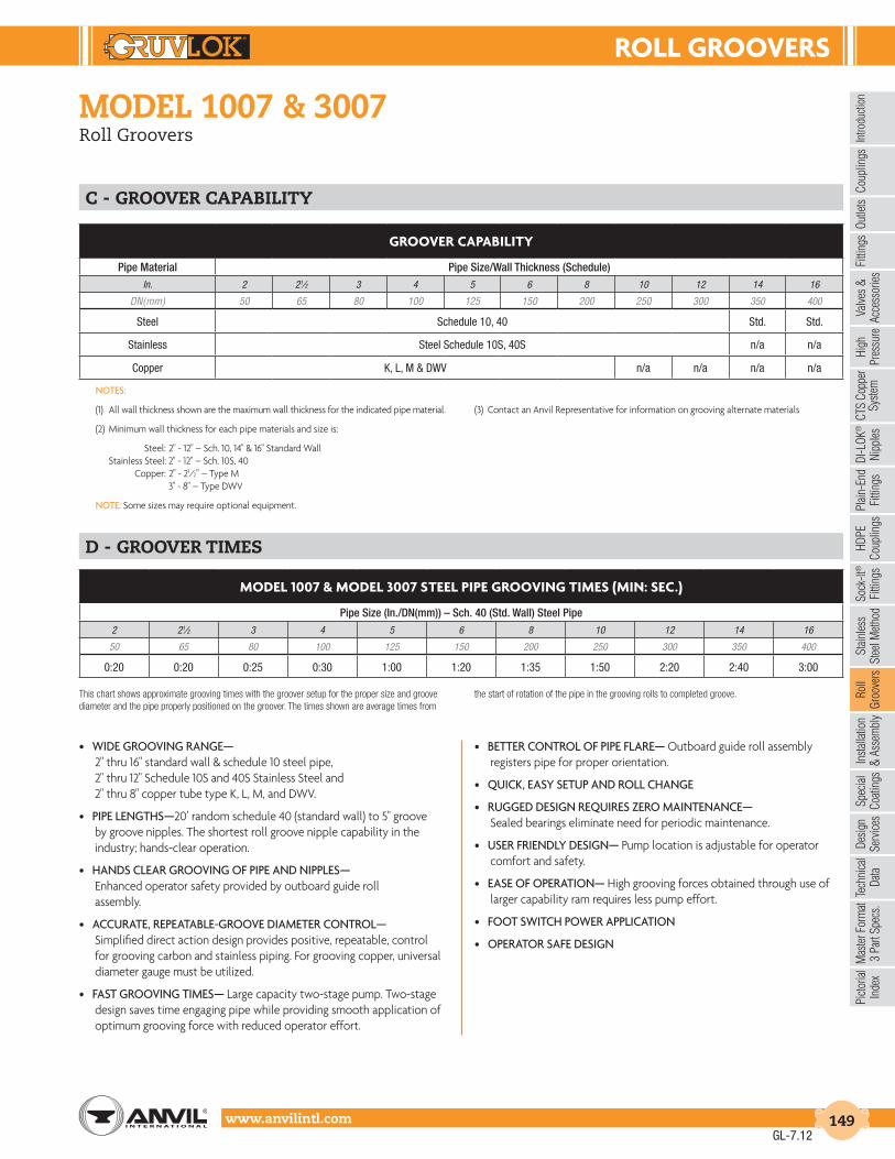
roLL GrooVErS
Intro
duct
ion
Coup
lings
Outle
tsFi
tting
sVa
lves
&
Acce
ssor
ies
High
Pres
sure
DI-L
OK®
Nipp
les
Plai
n-En
dFi
tting
sHD
PECo
uplin
gsSo
ck-It
®
Fitti
ngs
Stai
nles
sSt
eel M
etho
dRo
ll Gr
oove
rsIn
stal
latio
n&
Ass
embl
ySp
ecia
lCo
atin
gsDe
sign
Serv
ices
Tech
nica
lDa
taM
aste
r For
mat
3 Pa
rt Sp
ecs.
Pict
oria
lIn
dex
CTS
Copp
er
Syst
em
www.anvilintl.com 149
model 1007 & 3007Roll Groovers
• WIDE GROOVING RANGE— 2" thru 16" standard wall & schedule 10 steel pipe, 2" thru 12" Schedule 10S and 40S Stainless Steel and 2" thru 8" copper tube type K, L, M, and DWV.
• PIPE LENGTHS—20’ random schedule 40 (standard wall) to 5" groove by groove nipples. The shortest roll groove nipple capability in the industry; hands-clear operation.
• HANDS CLEAR GROOVING OF PIPE AND NIPPLES— Enhanced operator safety provided by outboard guide roll assembly.
• ACCURATE, REPEATABLE-GROOVE DIAMETER CONTROL— Simplified direct action design provides positive, repeatable, control for grooving carbon and stainless piping. For grooving copper, universal diameter gauge must be utilized.
• FAST GROOVING TIMES— Large capacity two-stage pump. Two-stage design saves time engaging pipe while providing smooth application of optimum grooving force with reduced operator effort.
• BETTER CONTROL OF PIPE FLARE— Outboard guide roll assembly registers pipe for proper orientation.
• QUICK, EASY SETUP AND ROLL CHANGE
• RUGGED DESIGN REQUIRES zERO MAINTENANCE— Sealed bearings eliminate need for periodic maintenance.
• USER FRIENDLY DESIGN— Pump location is adjustable for operator comfort and safety.
• EASE OF OPERATION— High grooving forces obtained through use of larger capability ram requires less pump effort.
• FOOT SWITCH POWER APPLICATION
• OPERATOR SAFE DESIGN
c - Groover capability
d - Groover times
NOTES:
(1) All wall thickness shown are the maximum wall thickness for the indicated pipe material.
(2) Minimum wall thickness for each pipe materials and size is:
Steel: 2" - 12" – Sch. 10, 14" & 16" Standard Wall Stainless Steel: 2" - 12" – Sch. 10S, 40 Copper: 2" - 21⁄2” – Type M 3" - 8" – Type DWV
NOTE: Some sizes may require optional equipment.
(3) Contact an Anvil Representative for information on grooving alternate materials
This chart shows approximate grooving times with the groover setup for the proper size and groove diameter and the pipe properly positioned on the groover. The times shown are average times from
the start of rotation of the pipe in the grooving rolls to completed groove.
GrooVEr cAPABILItY
Pipe Material Pipe Size/Wall Thickness (Schedule)In. 2 21⁄2 3 4 5 6 8 10 12 14 16
DN(mm) 50 65 80 100 125 150 200 250 300 350 400
Steel Schedule 10, 40 Std. Std.
Stainless Steel Schedule 10S, 40S n/a n/a
Copper K, L, M & DWV n/a n/a n/a n/a
ModEL 1007 & ModEL 3007 StEEL PIPE GrooVInG tIMES (MIn: SEc.)
Pipe Size (In./DN(mm)) – Sch. 40 (Std. Wall) Steel Pipe2 21⁄2 3 4 5 6 8 10 12 14 16
50 65 80 100 125 150 200 250 300 350 400
0:20 0:20 0:25 0:30 1:00 1:20 1:35 1:50 2:20 2:40 3:00
GL-7.12

roLL GrooVErS
www.anvilintl.com150
model 3006Roll Groover
The Gruvlok Model 3006 roll groover features a low maintenance quick roll change out design with the capability to groove 2" - 12" steel pipe, as well as 2" - 6" stainless steel. This machine is also compatible with the CTS Copper System for accurate and repeatable grooving of tube as small as 2" in diameter. Standard with each machine is the patented Gruvlok hands free nipple guide system. This one of a kind nipple guide system allows for the shortest nipple grooving in the business and is hands free for increased operator safety. A special hydraulic pump with a reduced height handle and pivoting location allow each operator to customize the machine for maximum comfort while grooving. Low cost, lightweight, user friendly, and reliable, the Model 3006 Roll Groover follows the quality Gruvlok tradition started with 1007/3007 models and takes the future of roll grooving one step further.
• WIDE GROOVING RANGE— 2" thru 8" Schedule 40 (standard wall) steel pipe,
10" (.188" Wall), 12" (.219” wall), and 2" thru 12" Sch. 10 2" thru 6" Schedule 10S and 40S Stainless Steel Pipe, and 2" thru 8" copper type K, L, M, and DWV.
• PIPE LENGTHS— 20' random Schedule 40 (standard wall) to 5" groove by groove nipples. The shortest roll groove nipple capability in the industry: hands clear
• HANDS-CLEAR GROOVING OF PIPE AND NIPPLES— Enhanced operator safety provided by outboard guide roll assembly
• ACCURATE, REPEATABLE GROOVE DIAMETER CONTROL— Simplified direct action provided positive, repeatable control for grooving carbon and stainless piping. For grooving copper, universal diameter gauge must be utilized.
• BETTER CONTROL OF PIPE FLARE— Outboard guide roll assembly registers pipe for proper orientation.
• QUICK, EASY SETUP AND ROLL CHANGE
• RUGGED DESIGN REQUIRES MINIMAL MAINTENANCE— Only periodic application of grease via grease fittings required.
• USER FRIENDLY DESIGN— Pump has a special reduced height handle and adjustable location for operator comfort and safety.
• EASE OF OPERATION— High grooving forces obtained though use of large capacity ram requires less pump effort.
Gruvlok roll grooving technology is protected by U.S. Patents5450738, 5570603, 5778715 and others pending.
GL-7.12

roLL GrooVErS
Intro
duct
ion
Coup
lings
Outle
tsFi
tting
sVa
lves
&
Acce
ssor
ies
High
Pres
sure
DI-L
OK®
Nipp
les
Plai
n-En
dFi
tting
sHD
PECo
uplin
gsSo
ck-It
®
Fitti
ngs
Stai
nles
sSt
eel M
etho
dRo
ll Gr
oove
rsIn
stal
latio
n&
Ass
embl
ySp
ecia
lCo
atin
gsDe
sign
Serv
ices
Tech
nica
lDa
taM
aste
r For
mat
3 Pa
rt Sp
ecs.
Pict
oria
lIn
dex
CTS
Copp
er
Syst
em
www.anvilintl.com 151
model 3006Roll Groover
Groover capability
Groover times
NOTES:
(1) All wall thickness shown are the maximum wall thickness for the indicated pipe material.
(2) Minimum wall thickness for each pipe materials and size is: Steel: All sizes – Sch. 10 Stainless Steel: 2" - 6" Sch. 10S, 40S Copper: 2", 21⁄2" – Type M 3" - 8" – Type DWV
(3) Please contact an Anvil Representative for more information on grooving alternate materials & wall thickness.
GROOVING TIMES: This chart shows approximate grooving times with the groover set-up for the proper size and groove diameter and the pipe properly
positioned on the groover. The times shown are average times from the start ofrotation of the pipe in the grooving rolls to completed groove.
StAndArd EQuIPMEnt:
Roll Groover complete with Adjustable Support Leg Assembly and roller sets for grooving 2"-6" and 8"-12" steel pipe, Steel/CTS Dual Guide Roll Assembly, hydraulic pump with pressure gauge, and two depth adjustment gauges. This unit is designed for direct attachment to your Ridgid® 300 Power Drive. Complete with comprehensive setup, operating and trouble-shooting instructions.
Shipped in a reusable wooden storage crate.
Approximate shipping weight: 225 pounds.
Required Ridgid® 300 Power Drive not included.
technical data – model 3006
GrooVEr cAPABILItY
Pipe Material Pipe Size/Wall Thickness (Schedule)1,2
In. 2 21⁄2 3 4 5 6 8 10 12
DN(mm) 50 65 80 100 125 150 200 250 300
Steel Schedule 10, 40 0.188" 0.219"
Stainless Steel Schedule 10S, 40S n/a n/a n/a
CTS Copper System K, L, M & DWV n/a n/a
ModEL 3006 StEEL PIPE GrooVInG tIMES (MIn: SEc.)
Pipe Size (In./DN(mm))/Max Steel Pipe Wall Thickness2 21⁄2 3 4 6 8 10 12
50 65 80 100 150 200 250 300
0:20 0:20 0:25 0:30 1:20 1:55 1:40 1:20
GL-7.12
oPtIonAL EQuIPMEnt: Advanced Copper Method (IPS Copper) Option: • Consisting of 2"-6" Advanced Copper Method roll set, Advanced Copper Method Guide Roll Assembly, and a 2"-6" Universal Diameter Gauge. • 2"-6" Universal Diameter Gauge.
CTS Copper System Option: • Consisting of 2"-8" roll set, 2"-6" CTS Depth Gauge, and 8" CTS Depth Gauge.

GruVLoK InStALLAtIon And ASSEMBLY
www.anvilintl.com152
couplinG installation & assembly
The instructions are based on pipe grooved in accordance withGruvlok® grooving specifications. Check pipe ends for proper groove dimensions and assure that the pipe ends are free of indentations and projections which would prevent proper sealing.
ALWAYS USE A GRUVLOK® LUBRICANT FOR PROPER COUPLINGASSEMBLY. Thorough lubrication of the external surface of the gasket is essential to prevent pinching and possible damage to the gasket. For temperatures above 150° F (65.6° C) use Gruvlok XtremeTM Lubricant and lubricate all gasket surfaces, internal and external. See Gruvlok Lubricants in the Technical Data section of the Gruvlok catalog for additional important information.
SPEcIFIEd BoLt torQuESpecified bolt torque is for the oval neck track bolts used onGruvlok® couplings and flanges. The nuts must be tightened alternately and evenly until fully tightened. Caution: Use of an impact wrench is not recommended because the torque output can vary significantly due to many variables including air pressure supply, battery strength and operational variations.cAutIon: Proper torquing of coupling bolts is required to obtain specified performance. Over torquing the bolts may result in damage to the bolt and/or casting which could result in pipe joint separation. Under torquing the bolts may result in lower pressure retention capabilities, lower bend load capabilities, joint leakage and pipe joint separation. Pipe joint separation may result in significant property damage and serious injury.
AnSI SPEcIFIEd BoLt torQuE
Bolt Size
Wrench Size
Specified Bolt Torque *
In. In. Ft.-Lbs
3⁄8 11⁄16 30-451⁄2 7⁄8 80-1005⁄8 11⁄16 100-1303⁄4 11⁄4 130-1807⁄8 17⁄16 180-2201 15⁄8 200-250
11⁄8 113⁄16 225-27511⁄4 2 250-300
MEtrIc SPEcIFIEd BoLt torQuE
Bolt Size
Wrench Size
Specified Bolt Torque *
mm mm N-m
M10 16 40-60M12 22 110-150M16 24 135-175M20 30 175-245M22 34 245-300M24 36 270-340
notE: Specified torques are to be used unless otherwise noted on Product Installation Instructions.
* Non-lubricated bolt torques.
* Non-lubricated bolt torques.
Installation & Assembly
table of contentsFIG. 7401 Rigidlok® Coupling ............................................... 153FIG. 7001 Standard Coupling .............................................. 154FIG. 7001-2 & FIG. 7401-2 2-Piece Large Dia. Couplings ..155FIG. 7011 Standard Coupling ................................................ 156FIG. 7000 Lightweight Flexible Coupling .................... 157FIG. 7400 Rigidlite® Coupling .............................................. 158FIG. 6400 Rigid Coupling ...................................................... 159FIG. 7003 HingelokTM Coupling ..........................................160FIG. 7010 Reducing Coupling .............................................. 161FIG. 7012 Gruvlok Flange (2" - 12") .............................162-163FIG. 7012 Gruvlok Flange (14" - 24") ..................................164FIG. 7042 Outlet Coupling ................................................. 165FIG. 7045 & FIG. 7046 Clamp-T® Branch Outlets. .....166FIG. 7044 Branch Outlet. ...................................................... 167FIG. 7005 Roughneck® Coupling........................................168FIG. 7004 High Pressure Coupling ....................................169FIG. 7004 High Pressure Coupling with EG Gasket ..170FIG. 7305 HDPE Coupling ....................................................... 171FIG. 7307 HDPE Transition Coupling ............................... 172FIG. 7312 HDPE Flange Adapter .......................................... 173Gruvlok Sock-It® Fitting ........................................................ 174Model FTV Tri-Service Valve ...................................... 175-178Series GBV-S & GBV-T Circuit Balancing Valves .. 179-181FIG. AF21-GG, -GF & -FF AnvilFlexTM .............................. 182
GL-7.12

GruVLoK InStALLAtIon And ASSEMBLY
Intro
duct
ion
Coup
lings
Outle
tsFi
tting
sVa
lves
&
Acce
ssor
ies
High
Pres
sure
DI-L
OK®
Nipp
les
Plai
n-En
dFi
tting
sHD
PECo
uplin
gsSo
ck-It
®
Fitti
ngs
Stai
nles
sSt
eel M
etho
dRo
ll Gr
oove
rsIn
stal
latio
n&
Ass
embl
ySp
ecia
lCo
atin
gsDe
sign
Serv
ices
Tech
nica
lDa
taM
aste
r For
mat
3 Pa
rt Sp
ecs.
Pict
oria
lIn
dex
CTS
Copp
er
Syst
em
www.anvilintl.com 153
fiG. 7401Rigidlok® Coupling
1check & lubricate Gasket— Check gasket to be sure it is compatible for
the intended service. Apply a thin coating of Gruvlok lubricant to the exterior surface and sealing lips of the gasket. Some applications require lubrication of the entire gasket surface. Be careful that foreign particles do not adhere to lubricated surfaces.
2 Gasket installation— Slip the gasket over the pipe end making sure the
gasket lip does not overhang the pipe end.
On couplings 10" and larger it may be easier toturn the gasket inside out thenlubricate and slide thegasket over the pipe end asshown.
3 aliGnment— After aligning the two pipe ends, pull the gasket into position
centering it between the grooves on each pipe.Gasket should not extend into the groove on either pipe.
On couplings 10" andlarger, flip or roll the gasketinto centered position.
4 housinGs— Remove one nut and bolt and loosen the other nut. Place one housing
over the gasket, making sure the housing keys fit into the pipe grooves. Swing the other housing over the gasket and into the grooves on both pipes, making sure the tongue and recess of each housing is properly mated. Reinsert the bolt and run-up both nuts finger tight.
5 tiGhten nuts— Securely tighten nuts alternately and equally to the specified
bolt torque, keeping the gaps at the bolt pads evenly spaced.
cAutIon: Uneven tightening may cause the gasket to pinch. Gasket should not be visible between segments after bolts are tightened.
6 assembly is complete— Visually inspect the pipe joint to assure
the coupling keys are fully engaged in the pipe grooves. The bolt pads are to have equal gaps on each side of the coupling.
cAutIon: Use of an impact wrench is not recommended because the torque output can vary significantly due to many variables including air pressure supply, battery strength and operational variations.
cAutIon: Proper torquing of coupling bolts is required to obtain specified performance. Over torquing the bolts may result in damage to the bolt and/or casting which could result in pipe joint separation. Under torquing the bolts may result in lower pressure retention capabilities, lower bend load capabilities, joint leakage and pipe joint separation. Pipe joint separation may result in significant property damage and serious injury.
notE: Sizes 16" and larger are cast in multiple segments. To install the larger sizes align the tongue and pocket of the couplings appropriately and tighten the nuts alternately to the specified bolt torque. When properly assembled there will be a small equal gap between the adjacent bolt pads.
GL-7.12

GruVLoK InStALLAtIon And ASSEMBLY
www.anvilintl.com154
fiG. 7001Standard Coupling
1check & lubricate Gasket—Check gasket to be sure it is compatible
for the intended service. Apply a thin coating of Gruvlok lubricant to the exterior surface and sealing lips of the gasket. Be careful that foreign particles do not adhere to lubricated surfaces.
2 Gasket installation— Slip the gasket over the pipe end making sure the
gasket lip does not overhang the pipe end.
On couplings 10" and larger it may beeasier to turn the gasketinside out then lubricateand slide the gasket overthe pipe end as shown.
3 aliGnment— After aligning the two pipe ends, pull the gasket into position
centering it between the grooves on each should not extend into the groove on either pipe.
On couplings 10" andlarger, flip or roll thegasket into centeredposition.
4 housinGs— Place the coupling housing halves over the gasket making sure
the housing keys engage the grooves. Insert bolts and turn nuts finger tight.
5 tiGhten nuts— Tighten the nuts alternately and equally to the specified bolt
torque. The housing bolt pads must make metal-to-metal contact.
cAutIon: Uneven tightening may cause the gasket to pinch.
6 assembly is complete— Visually inspect the pipe joint to assure
the coupling keys are fully engaged in the pipe grooves and the bolt pads are in firm even metal-to-metal contact on both sides of the coupling.
notE: The housings for sizes 16” and larger are cast in four or more segments.
to InStALL: Loosely pre-assemble the segments into two “Housing Halves” making sure that the alignment tang(s) and slot(s) on the bolt pad(s) are properly mated. Install the “Housing Halves” as shown in steps 4 & 5. The coupling is properly installed when all bolt pads are firmly together - Metal-to-Metal.
cAutIon: Proper torquing of coupling bolts is required to obtain specified performance. Over torquing the bolts may result in damage to the bolt and/or casting which could result in pipe joint separation. Under torquing the bolts may result in lower pressure retention capabilities, lower bend load capabilities, joint leakage and pipe joint separation. Pipe joint separation may result in significant property damage and serious injury.
cAutIon: Use of an impact wrench is not recommended because the torque output can vary significantly due to many variables including air pressure supply, battery strength and operational variations.
GL-7.12

GruVLoK InStALLAtIon And ASSEMBLY
Intro
duct
ion
Coup
lings
Outle
tsFi
tting
sVa
lves
&
Acce
ssor
ies
High
Pres
sure
DI-L
OK®
Nipp
les
Plai
n-En
dFi
tting
sHD
PECo
uplin
gsSo
ck-It
®
Fitti
ngs
Stai
nles
sSt
eel M
etho
dRo
ll Gr
oove
rsIn
stal
latio
n&
Ass
embl
ySp
ecia
lCo
atin
gsDe
sign
Serv
ices
Tech
nica
lDa
taM
aste
r For
mat
3 Pa
rt Sp
ecs.
Pict
oria
lIn
dex
CTS
Copp
er
Syst
em
www.anvilintl.com 155
fiG. 7001-2 & fiG. 7401-22-Piece Large Diameter Standard Groove Couplings
1check & lubricate Gasket— Check gasket to be sure it is compatible for
the intended service. Apply a thin coat of Gruvlok lubricant to the exterior surface and sealing lips of the gasket. Be careful that foreign particles do not adhere to lubricated surfaces.
2 Gasket installation— Slip the gasket over the pipe end, making sure the
gasket lip does not overhang the pipe end.3 aliGnment— After aligning the two
pipe ends together, pull the gasket into position, centering it between the grooves on each pipe. Gasket should not extend into the groove on either pipe.
4 housinG— Place each housing half on the pipe and into each groove making sure
that the gasket does not slip out of position in between the pipe ends or groove.
5bolts— Apply a thin coat of Xtreme lube, or Gruvlok Standard Lube to the bolt
threads. Tighten the nuts alternately and equally to the specified bolt torque.
cAutIon: Uneven tightening may cause the gasket to pinch.
6 final assembly— Visually inspect the pipe joint to assure the coupling keys are
fully engaged in the pipe grooves, the bolt pads are in firm even metal-to-metal contact on both sides of the coupling, and gasket is not visible.
AnSI SPEcIFIEd BoLt torQuE
Pipe Sizes Bolt Size Specified Bolt Torque LubricationIn. In. Ft.-Lbs –
14 7⁄8 180 - 220
Gruvlok Xtreme™ Lubricant
16 1 250 - 300
18 1 250 - 300
20 11⁄8 375 - 425
24 11⁄8 375 - 425
• 7001-2 & 7401-2 bolts must be lightly coated with Gruvlok Xtreme™ lube before installation. See chart for torque requirements.• Minimum wall pipe suitable for 14" – 24": 7001-2 & 7401-2 roll grooved installation is 0.250" wall thickness• Pipe preparation Grooved dimensions must conform to the Gruvlok Roll/Cut groove specification
cAutIon: When using an impact wrench, verify that the torque output on the wrench is within the required torque range.
GL-7.12

GruVLoK InStALLAtIon And ASSEMBLY
www.anvilintl.com156
fiG. 7011Standard Coupling
2Turn the gasket inside out and slide the gasket completely
over one of the pipe ends. Turning the gasket inside out will reduce the stretching necessary to put the gasket into position. Ideally, approximately 75% of the pipe’s gasket-sealing surface, (Dimension A) should be visible when the gasket is in proper position. This will aid in step 4.
3Lubricate the gasket sealing lips. The use of Gruvlok
lubricants ensures compatibility between the lubricant and the gasket.
4Pull the two pipes into contact aligning the pipe ends.
cAutIon: Be careful not to pinch fingers during this step. Working your way around the circumference of the pipe, flip the gasket toward the pipe end so that the proper side is facing out. The end of this procedure will result in the gasket snapping into place. Position the gasket centrally between the grooves of the two pipe ends.
1 Inspect the pipe ends making sure the criteria, in the
Gruvlok Large Diameter Pipe Roll and Cut Groove Specifications, are met.
5Lubricate the exterior surface of the gasket. This helps pre-
vent pinching of the gasket during assembly.
6Secure the housings about the pipes making sure the coupling
keys are engaged in the pipe end grooves. Hint: For horizontal assem-bly, place housing segment on top of the pipe to support the weight of the housing segment. Secure the adjacent housing with an oval neck track bolt and heavy hex nut and then rotate the secured housings, again balancing the weight of the housings on the top of the pipe. Continue this procedure for all segments.
7Firmly torque each bolt. The specified minimum torque for
each nut is 600 ft.-lbs. The speci-fied maximum torque for each nut is 800 ft.-lbs.
8Installation of the Figure 7011 Standard Coupling is
completed.
cAutIon: Use of an impact wrench is not recommended because the torque output can vary significantly due to many variables including air pressure supply, battery strength and operational variations.
cAutIon: Proper torquing of coupling bolts is required to obtain specified performance. Over torquing the bolts may result in damage to the bolt and/or casting which could result in pipe joint separation. Under torquing the bolts may result in lower pressure retention capabilities, lower bend load capabilities, joint leakage and pipe joint separation. Pipe joint separation may result in significant property damage and serious injury.
GL-6.11

GruVLoK InStALLAtIon And ASSEMBLY
Intro
duct
ion
Coup
lings
Outle
tsFi
tting
sVa
lves
&
Acce
ssor
ies
High
Pres
sure
DI-L
OK®
Nipp
les
Plai
n-En
dFi
tting
sHD
PECo
uplin
gsSo
ck-It
®
Fitti
ngs
Stai
nles
sSt
eel M
etho
dRo
ll Gr
oove
rsIn
stal
latio
n&
Ass
embl
ySp
ecia
lCo
atin
gsDe
sign
Serv
ices
Tech
nica
lDa
taM
aste
r For
mat
3 Pa
rt Sp
ecs.
Pict
oria
lIn
dex
CTS
Copp
er
Syst
em
www.anvilintl.com 157
fiG. 7000Lightweight Flexible Coupling
1 check & lubricate Gasket—Check gasket to be sure it is compatible
for the intended service. Apply a thin coating of Gruvlok lubricant to the exterior surface and sealing lips of the gasket. Be careful that foreign particles do not adhere to lubricated surfaces.
2 Gasket installation— Slip the gasket over the pipe end, making sure the
gasket lip does not overhang the pipe end.3 aliGnment— After aligning the two
pipe ends together, pull the gasket into position, centering it between the grooves on each pipe. Gasket should not extend into the groove on either pipe.
4 housinGs— With one nut unthreaded to the end of the bolt, unthread the other
nut completely and swing the coupling housing halves over the gasket, making sure the housing keys engage the grooves. Insert the bolt and turn the nuts finger tight.
5 tiGhten nuts— Tighten the nuts alternately and equally to the specified bolt
torque. The housing bolt pads must make metal-to-metal contact.
cAutIon: Uneven tightening may cause the gasket to pinch.
6 assembly is complete— Visually inspect the pipe joint to assure the
coupling keys are fully engaged in the pipe grooves and the bolt pads are in firm even metal-to-metal contact on both sides of the coupling.
cAutIon: Use of an impact wrench is not recommended because the torque output can vary significantly due to many variables including air pressure supply, battery strength and operational variations.
cAutIon: Proper torquing of coupling bolts is required to obtain specified performance. Over torquing the bolts may result in damage to the bolt and/or casting which could result in pipe joint separation. Under torquing the bolts may result in lower pressure retention capabilities, lower bend load capabilities, joint leakage and pipe joint separation. Pipe joint separation may result in significant property damage and serious injury.
GL-7.12

GruVLoK InStALLAtIon And ASSEMBLY
www.anvilintl.com158
fiG. 7400Rigidlite® Coupling
1check & lubricate Gasket— Check the gasket to be sure it is compatible
for the intended service. Apply a thin coating of Gruvlok Xtreme Lubricant to the entire surface, both internal and external, of the gasket. Be careful that foreign particles do not adhere to lubricated surfaces.
2 Gasket installation— Slip the gasket over the one tube, making sure the
gasket lip does not overhang the tube end.3 aliGnment— After aligning the two
tube ends together, pull the gasket into position, centering it between the grooves on each tube. The gasket should not extend into the groove on either tube.
4 housinGs— Remove one nut and bolt and loosen the other nut. Place one housing
over the gasket, making sure the housing keys fit into the tube grooves. Swing the other housing over the gasket and into the grooves on both tubes, making sure the tongue and recess of each housing is properly mated. Reinsert the bolt and run-up both nuts finger tight.
5 tiGhten nuts— Securely tighten nuts alternately and equally to the specified
bolt torque, keeping the gaps at the bolt pads evenly spaced.
cAutIon: Uneven tightening may cause the gasket to pinch. Gasket should not be visible between segments after bolts are tightened.
6 assembly is complete— Visually inspect the pipe joint to assure the coupling
keys are fully engaged in the pipe grooves. The bolt pads are to have equal gaps on each side of the coupling.
cAutIon: Use of an impact wrench is not recommended because the torque output can vary significantly due to many variables including air pressure supply, battery strength and operational variations.
cAutIon: Proper torquing of coupling bolts is required to obtain specified performance. Over torquing the bolts may result in damage to the bolt and/or casting which could result in pipe joint separation. Under torquing the bolts may result in lower pressure retention capabilities, lower bend load capabilities, joint leakage and pipe joint separation. Pipe joint separation may result in significant property damage and serious injury.
GL-6.11

GruVLoK InStALLAtIon And ASSEMBLY
Intro
duct
ion
Coup
lings
Outle
tsFi
tting
sVa
lves
&
Acce
ssor
ies
High
Pres
sure
DI-L
OK®
Nipp
les
Plai
n-En
dFi
tting
sHD
PECo
uplin
gsSo
ck-It
®
Fitti
ngs
Stai
nles
sSt
eel M
etho
dRo
ll Gr
oove
rsIn
stal
latio
n&
Ass
embl
ySp
ecia
lCo
atin
gsDe
sign
Serv
ices
Tech
nica
lDa
taM
aste
r For
mat
3 Pa
rt Sp
ecs.
Pict
oria
lIn
dex
CTS
Copp
er
Syst
em
www.anvilintl.com 159
fiG. 6400Rigid Coupling
The Fig. 6400 Coupling from Gruvlok is specially designed to provide a rigid pipe connection to meet the specific demands of copper tubing installation. Fast and easy swing-over installation of the rugged lightweight housing produces a secure, rigid pipe joint. Available with the EPDM flush gap style gasket as the standard gasket.
cAutIon: Uneven tightening may cause the gasket to pinch. The gasket should not be visible between segments after the bolts are tightened. Proper torquing of coupling bolts is required to obtain specified performance. Over torquing the bolts may result in damage to the bolt and/or casting which could result in pipe joint separation. Under torquing the bolts may result in lower pressure retention capabilities, lower bend load capabilities, joint leakage and pipe joint separation.
SPEcIFIEd BoLt torQuE
Bolt Size Wrench Size Specified Bolt Torque*
In. In. Ft.-Lbs3⁄8 11⁄16 30-451⁄2 7⁄8 30-455⁄8 11⁄16 60-90
* Non-lubricated bolt torques.
1 check & lubricate Gasket– Check the gasket to be sure it is compatible
for the intended service. Apply a thin coating of Gruvlok® Xtreme Lubricant to the entire surface, both internal and external, of the gasket. Be careful that foreign particles do not adhere to the lubricated surfaces.
2Gasket installation– Slip the gasket over one tube, making sure the
gasket lip does not overhang the tube end.
3aliGnment– After aligning the two tube ends together, pull the gasket into
position, centering it between the grooves on each tube. The gasket should not extend into the groove on either tube or between the tube ends.
4housinGs– Remove one nut and bolt and loosen the other nut. Place one
housing over the gasket, making sure the housing keys fit into the tube grooves. Swing the other housing over the gasket and into the grooves on both tubes, making sure the tongue and recess of each housing is properly mated. Re-insert the bolt and run-up both nuts finger tight.
5tiGhten nuts– Securely tighten nuts alternately and equally to the
specified bolt torque, keeping the gaps at the bolt pads evenly spaced. Assembly is complete. Visually inspect the pipe joint to assure the coupling keys are fully engaged in the pipe grooves. The bolt pads are to have equal gaps on each side of the coupling.
notE: Copper is a soft material, in some cases, the bolt pads may come close to metal-to-metal contact.
cAutIon: Uneven tightening may cause the gasket to pinch. The gasket should not be visible between segments after the bolts are tightened. Proper torquing of coupling bolts is required to obtain specified performance. Over torquing the bolts may result in damage to the bolt and/or casting which could result in pipe joint separation. Under torquing the bolts may result in lower pressure retention capabilities, lower bend load capabilities, joint leakage and pipe joint separation.
GL-7.12

GruVLoK InStALLAtIon And ASSEMBLY
www.anvilintl.com160
fiG. 7003Hingelok™ Coupling
1check & lubricate Gasket— Check gasket to be sure it is compatible for
the intended service. Apply a thin coating of Gruvlok lubricant to the exterior surface and sealing lips of the gasket. Be careful that foreign particles do not adhere to lubricated surfaces.
2 Gasket installation— Slip the gasket over the pipe end making sure the
gasket lip does not overhang the pipe end.3 aliGnment— After aligning the two
pipe ends, pull the gasket into position centering it between the grooves on each pipe. Gasket should not extend into the groove on either pipe.
4 housinGs— Put one half of the open coupling over the gasket as the coupling
keys fit firmly into the grooves on each pipe end. Swing the other half of the coupling into position around the gasket and into the grooves.
5 lock couplinG— Fit the nose of the locking handle in the notch of the opposite
housing. Press firmly down on the handle until it makes contact with the coupling housing. Insert locking pin into handle linkage to secure handle in closed position. (See Caution.)
6 assembly is complete— Visually inspect the pipe joint to assure the coupling
keys are fully engaged in the pipe grooves and the bolt pads are in firm even metal-to-metal contact on both sides of the coupling.
cAutIon:
1) Hammering or banging on the handle or coupling housing could cause serious damage to the locking device and coupling assembly. The result may be an unsuitable pipe joint and unusable coupling assembly.
2) Care needs to be taken so that fingers do not get caught or pinched when handle is placed in locked position as a result of cam action of handle assembly.
3) When re-using coupling and gasket, always inspect gasket for damage and hinge/handle assembly for looseness, distortion or any other damage.
NOTE: Remove locking pin from handle before opening coupling.
GL-7.12

GruVLoK InStALLAtIon And ASSEMBLY
Intro
duct
ion
Coup
lings
Outle
tsFi
tting
sVa
lves
&
Acce
ssor
ies
High
Pres
sure
DI-L
OK®
Nipp
les
Plai
n-En
dFi
tting
sHD
PECo
uplin
gsSo
ck-It
®
Fitti
ngs
Stai
nles
sSt
eel M
etho
dRo
ll Gr
oove
rsIn
stal
latio
n&
Ass
embl
ySp
ecia
lCo
atin
gsDe
sign
Serv
ices
Tech
nica
lDa
taM
aste
r For
mat
3 Pa
rt Sp
ecs.
Pict
oria
lIn
dex
CTS
Copp
er
Syst
em
www.anvilintl.com 161
fiG. 7010Reducing Coupling
1check & lubricate Gasket— check gasket to be sure it is compatible for
the intended service. Apply a thin coating of Gruvlok lubricant to the exterior surface and sealing lips of the gasket. Be careful that foreign particles do not adhere to lubricated surfaces.
2 Gasket installation— Place the smaller opening of the gasket over the
smaller pipe. Angle the gasket over the pipe end and pull the gasket lip open around the circumference of the pipe. The center leg of the gasket should make flush contact with the pipe end and will prevent telescoping of the smaller pipe inside the larger.
3 aliGnment— Align the adjoining pipe center lines, and insert the larger pipe end
into the gasket. Angle the pipe end slightly to the face of the gasket and tilt the pipe into the gasket to ease assembly.
cAutIon: Use of an impact wrench is not recommended because the torque output can vary significantly due to many variables including air pressure supply, battery strength and operational variations.
cAutIon: Proper torquing of coupling bolts is required to obtain specified performance. Over torquing the bolts may result in damage to the bolt and/or casting which could result in pipe joint separation. Under torquing the bolts may result in lower pressure retention capabilities, lower bend load capabilities, joint leakage and pipe joint separation. Pipe joint separation may result in significant property damage and serious injury.
4 housinGs— Place the coupling housing halves over
the gasket making sure the housing keys engage the grooves. Insert bolts and turn nuts finger tight.
5 tiGhten nuts— Tighten the nuts alternately
and equally to the specified bolt torque. The housing bolt pads must make metal-to-metal contact.
cAutIon: Uneven tightening may cause the gasket to pinch.
6 assembly complete— Visually inspect the pipe joint
to assure the coupling keys are fully engaged in the pipe grooves and the bolt pads are in firm even metal-to-metal contact on both sides of the coupling.
notE: Fig. A illustrates the correctposition of the Fig. 7010 ReducingCoupling gasket and housing properly assembled onto adjacent pipe ends.cAutIon: In vertical installationsthe pipes must be supported to prevent telescoping during installation.
GasketCenter Rib
ProperPosition of
The GasketSealing Lips
Gasket ReducingCouplingHousing
fiG. a
GL-7.12

GruVLoK InStALLAtIon And ASSEMBLY
www.anvilintl.com162
fiG. 7012Gruvlok Flange (2"–12")
APPLIcAtIonS WHIcH rEQuIrE A GruVLoK® FLAnGE AdAPtEr InSErt:
1. When mating to a wafer valve (lug valve), if the valve is rubber faced in the area designated by the sealing surface dimensions (A Max. to B Min.), place the Gruvlok Flange Adapter Insert between the valve and the Gruvlok Flange.
2. When mating to a rubber-faced metal flange, the Gruvlok Flange Adapter Insert is placed between the Gruvlok Flange and the rubber-faced flange.
3. When mating to a serrated flange surface, a standard full-faced flange gasket is installed against the serrated flange face, and the Gruvlok Flange Adapter Insert is placed between the Gruvlok Flange and the standard flange gasket.
4. When mating to valves or other component equipment where the flange face has an insert, use procedure described in note 3.
Check pipe end for proper grooved dimensions and to assure that the pipe end is free of indentations and projections that would prevent proper sealing of the Gruvlok flange gasket.
1On the side without the hinge pin, loosen the latch bolt nut to the end of the bolt
thread. (It is not necessary to remove the nut from the latch bolt.) Swing the latch bolt out of the slot. Open the Gruvlok Flange and place around the grooved pipe end with the key section fitting into the groove. The flange gasket cavity must face the pipe end.
2Place the latch bolt back into the slotted hole. Tighten the nut until there is a 1/16" gap
between the flange halves at location “A”. (See Figure below)
3Check the gasket to assure that it is properly suited for the intended service.
Lubricate the entire exterior surface of the gasket, including the sealing lips, using the proper Gruvlok lubricant.
The Gruvlok Flange gasket must be inserted so that the sealing lips face toward the pipe end and the mating flange. The lip of the gasket, sealing on the pipe, should not extend beyond the pipe end. The pipe should extend out beyond the end of the sealing lip by approximately 1/8" on the 2"-6" sizes and 3/16" on the 8"-12" sizes.
"A"
Latch Bolt
Gasket
Note: This side mustface the mating flange
GL-6.11

GruVLoK InStALLAtIon And ASSEMBLY
Intro
duct
ion
Coup
lings
Outle
tsFi
tting
sVa
lves
&
Acce
ssor
ies
High
Pres
sure
DI-L
OK®
Nipp
les
Plai
n-En
dFi
tting
sHD
PECo
uplin
gsSo
ck-It
®
Fitti
ngs
Stai
nles
sSt
eel M
etho
dRo
ll Gr
oove
rsIn
stal
latio
n&
Ass
embl
ySp
ecia
lCo
atin
gsDe
sign
Serv
ices
Tech
nica
lDa
taM
aste
r For
mat
3 Pa
rt Sp
ecs.
Pict
oria
lIn
dex
CTS
Copp
er
Syst
em
www.anvilintl.com 163
4Stretch the Gruvlok gasket around the pipe end and then press the gasket into the
cavity between the pipe O.D. and the flange. The gasket must be properly positioned as shown in the figure below.
5With the gasket in place apply lubricant to the exposed gasket tip, which will seal
on the mating flange. tighten the nuts on the latch bolts alternately to the specified latch bolt torque. the flange housings must be in firm metal-to-metal contact.
6Verify that the mating flange face is hard, flat and smooth, free of indentations, which
would prevent proper sealing of the Gruvlok Flange gasket. Assure the gasket is still in the proper position and align Gruvlok Flange bolt holes with the mating flange, pump, tank, etc., bolt holes.
fiG. 7012Gruvlok Flange (2"–12")
7Insert a flange bolt or stud with material properties of SAE J429 Grade 5 or higher
through the bolt holes and thread a nut on hand tight. Continue this procedure until all bolt holes have been fitted. Tighten the nuts alternately and evenly so the flange faces remain parallel. All the bolts or studs must be torqued to the mating flange bolts specified torque. The flange faces should have metal-to-metal contact.
It is important to line up the boltholes before bringing the two flangestogether. Sliding the flanges into
place will dislodge the gasket and cause leakage to occur. When using a flange insert, it is important that the insert is properly aligned with the gasket prior to tightening the bolts.
NOTE: The Gruvlok Fig. 7012 Flange requires the use of a Flange Adapter Insert when used against rubber surfaces (Figure C1), serrated flange surfaces or mating flanges with inserts (Figure C2). TheFlange Adapter Insert will be exposedto the fluids in the system. Ensure thatthe Insert is compatible with the fluidsin the systems and with adjacent pipingcomponents.
Do not use asteel FlangeAdapter Insert
in copper systems or in systems wheregalvanic corrosion is possible.
CAUTION: Proper torquing of flange bolts is required to obtain specified performance. Over torquing the bolts may result in damage to the bolt and/or casting which could result in pipe joint separation. Under torquing the bolts may result in lower pressure retention capabilities, lower bend load capabilities, joint leakage and pipe joint separation. Pipe joint separationmay result in significant property damage and serious injury.
CAUTION: Use of an impact wrench is not recommended because the torque output can vary significantly due to many variables including air pressure supply, battery strength and operational variations.
fiG. c1 fiG. c2
GL-6.11
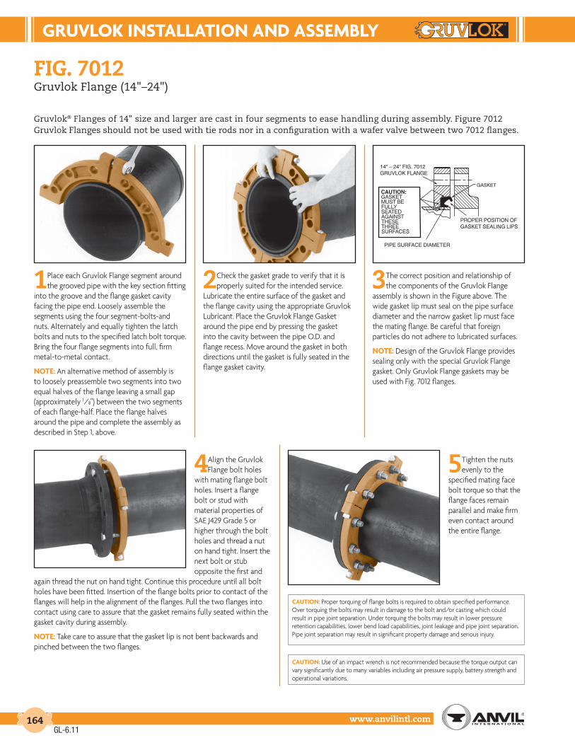
GruVLoK InStALLAtIon And ASSEMBLY
www.anvilintl.com164
fiG. 7012Gruvlok Flange (14"–24")
Gruvlok® Flanges of 14" size and larger are cast in four segments to ease handling during assembly. Figure 7012 Gruvlok Flanges should not be used with tie rods nor in a configuration with a wafer valve between two 7012 flanges.
1Place each Gruvlok Flange segment around the grooved pipe with the key section fitting
into the groove and the flange gasket cavity facing the pipe end. Loosely assemble the segments using the four segment-bolts-and nuts. Alternately and equally tighten the latch bolts and nuts to the specified latch bolt torque. Bring the four flange segments into full, firm metal-to-metal contact.
notE: An alternative method of assembly is to loosely preassemble two segments into two equal halves of the flange leaving a small gap (approximately 1/8") between the two segments of each flange-half. Place the flange halves around the pipe and complete the assembly as described in Step 1, above.
2Check the gasket grade to verify that it is properly suited for the intended service.
Lubricate the entire surface of the gasket and the flange cavity using the appropriate Gruvlok Lubricant. Place the Gruvlok Flange Gasket around the pipe end by pressing the gasket into the cavity between the pipe O.D. and flange recess. Move around the gasket in both directions until the gasket is fully seated in the flange gasket cavity.
3The correct position and relationship of the components of the Gruvlok Flange
assembly is shown in the Figure above. The wide gasket lip must seal on the pipe surface diameter and the narrow gasket lip must face the mating flange. Be careful that foreign particles do not adhere to lubricated surfaces.
notE: Design of the Gruvlok Flange provides sealing only with the special Gruvlok Flange gasket. Only Gruvlok Flange gaskets may be used with Fig. 7012 flanges.
4Align the Gruvlok Flange bolt holes
with mating flange bolt holes. Insert a flange bolt or stud with material properties of SAE J429 Grade 5 or higher through the bolt holes and thread a nut on hand tight. Insert the next bolt or stub opposite the first and
again thread the nut on hand tight. Continue this procedure until all bolt holes have been fitted. Insertion of the flange bolts prior to contact of the flanges will help in the alignment of the flanges. Pull the two flanges into contact using care to assure that the gasket remains fully seated within the gasket cavity during assembly.
notE: Take care to assure that the gasket lip is not bent backwards and pinched between the two flanges.
5Tighten the nuts evenly to the
specified mating face bolt torque so that the flange faces remain parallel and make firm even contact around the entire flange.
cAutIon: Proper torquing of flange bolts is required to obtain specified performance. Over torquing the bolts may result in damage to the bolt and/or casting which could result in pipe joint separation. Under torquing the bolts may result in lower pressure retention capabilities, lower bend load capabilities, joint leakage and pipe joint separation. Pipe joint separation may result in significant property damage and serious injury.
cAutIon: Use of an impact wrench is not recommended because the torque output can vary significantly due to many variables including air pressure supply, battery strength and operational variations.
CAUTION:GASKET MUST BE FULLY SEATED AGAINST THESE THREE SURFACES
14" – 24" FIG. 7012GRUVLOK FLANGE
GASKET
PROPER POSITION OFGASKET SEALING LIPS
PIPE SURFACE DIAMETER
GL-6.11

GruVLoK InStALLAtIon And ASSEMBLY
Intro
duct
ion
Coup
lings
Outle
tsFi
tting
sVa
lves
&
Acce
ssor
ies
High
Pres
sure
DI-L
OK®
Nipp
les
Plai
n-En
dFi
tting
sHD
PECo
uplin
gsSo
ck-It
®
Fitti
ngs
Stai
nles
sSt
eel M
etho
dRo
ll Gr
oove
rsIn
stal
latio
n&
Ass
embl
ySp
ecia
lCo
atin
gsDe
sign
Serv
ices
Tech
nica
lDa
taM
aste
r For
mat
3 Pa
rt Sp
ecs.
Pict
oria
lIn
dex
CTS
Copp
er
Syst
em
www.anvilintl.com 165
fiG. 7042Outlet Coupling
These instructions are based on pipe grooved in accordance with Gruvlok® grooving specifications. Check pipe ends for proper groove dimensions and to assure that the pipe ends are free of indentations and projections which would prevent proper sealing.
ALWAYS USE A GRUVLOK LUBRICANT FOR PROPER COUPLING ASSEMBLY. Thorough lubrication of the gasket is essential to prevent pinching and possible damage to the gasket.
1check & lubricate Gasket— Check gasket to
be sure it is compatible for the intended service. Apply a thin coating of Gruvlok lubricant to the exterior surface and sealing lips of the gasket. Be careful that foreign particles do not adhere to lubricated surfaces.
2Gasket installation— Slip
the gasket over one pipe end making sure the pipe abuts the gasket’s center ribs.
3aliGnment— Align the pipe ends and pull the pipe into
the gasket until the center ribs are in contact with the pipe ends. The gasket should not extend into the groove on either pipe. Rotate the gasket to align the outlet of the gasket to the same direction as the branch outlet.
4 housinG assembly—With one nut and bolt
removed and the other loosened, place one side of the housing over the gasket. Make sure the ribs on the outside of the gasket align with the recesses in the housing and the keys in the housing are in the grooves on both pipes. Swing the other housing over the gasket and into the grooves on both sides of the pipe. Make sure the recess in the outlet of the housing is properly aligned with gasket outlet.
5tiGhten nuts— Re-insert the bolt and run-up
both nuts finger tight. Securely tighten the nuts alternately and equally until they are completely tightened and there is no gap between the bolt pads. Continue tightening the nuts alternately and equally until the specified bolt torque is reached.
cAutIon: Make sure the ribs on the exterior of the gasket are enclosed in the housing recesses.
6assembly is complete
FIG. 7042 – SPEcIFIEd BoLt torQuE
Specified bolt torque is for the oval neck track bolts used on Gruvlok® couplings and flanges. The nuts must be tightened alternately and evenly until fully tightened. Caution: Use of an impact wrench is not recommended because the torque output can vary significantly due to many variables including air pressure supply, battery strength and operational variations.
cAutIon: Proper torquing of coupling bolts is required to obtain specified performance. Over torquing the bolts may result in damage to the bolt and/or casting which could result in pipe joint separation. Under torquing the bolts may result in lower pressure retention capabilities, lower bend load capabilities, joint leakage and pipe joint separation. Pipe joint separation may result in significantproperty damage and serious injury.
* Non-lubricated bolt torques.
AnSI SPEcIFIEd BoLt torQuE
Coupling Size
Bolt Size
Wrench Size
Specified Bolt Torque *
In. In. In. Ft.-Lbs.
11⁄2 3⁄8 x 21⁄8 11⁄16 30-452 3⁄8 x 21⁄2 11⁄16 30-45
21⁄2 1⁄2 x 23⁄8 7⁄8 80-1003 1⁄2 x 3 7⁄8 80-1004 5⁄8 x 31⁄2 11⁄16 100-1306 5⁄8 x 31⁄2 11⁄16 100-130
GL-7.12
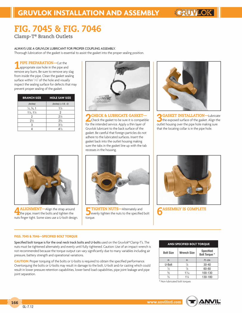
GruVLoK InStALLAtIon And ASSEMBLY
www.anvilintl.com166
fiG. 7045 & fiG. 7046Clamp-T® Branch Outlets
ALWAYS USE A GRUVLOK LUBRICANT FOR PROPER COUPLING ASSEMBLY.Thorough lubrication of the gasket is essential to assist the gasket into the proper sealing position.
1pipe preparation—Cut the appropriate size hole in the pipe and
remove any burrs. Be sure to remove any slag from inside the pipe. Clean the gasket sealing surface within 5/8" of the hole and visually inspect the sealing surface for defects that may prevent proper sealing of the gasket.
2check & lubricate Gasket—Check the gasket to be sure it is compatible
for the intended service. Apply a thin layer of Gruvlok lubricant to the back surface of the gasket. Be careful that foreign particles do not adhere to the lubricated surfaces. Insert the gasket back into the outlet housing making sure the tabs in the gasket line up with the tab recesses in the housing.
3Gasket installation—Lubricate the exposed surface of the gasket. Align the
outlet housing over the pipe hole making sure that the locating collar is in the pipe hole.
4aliGnment—Align the strap around the pipe, insert the bolts and tighten the
nuts finger tight. Some sizes use a U-bolt design.5 tiGhten nuts—Alternately and
evenly tighten the nuts to the specified bolt torque.
6assembly is complete
FIGS. 7045 & 7046—SPEcIFIEd BoLt torQuE
Specified bolt torque is for the oval neck track bolts and U-bolts used on the Gruvlok® Clamp-T’s. The nuts must be tightened alternately and evenly until fully tightened. Caution: Use of an impact wrench is not recommended because the torque output can vary significantly due to many variables including air pressure, battery strength and operational variations.
cAutIon: Proper torquing of the bolts or U-bolts is required to obtain the specified performance. Overtorquing the bolts or U-bolts may result in damage to the bolt, U-bolt and/or casting which could result in lower pressure retention capabilities, lower bend load capabilities, pipe joint leakage and pipe joint separation.
* Non-lubricated bolt torques
BrAncH SIZE HoLE SAW SIZE
(Inches) (Inches) (+1/8, -0)
1⁄2, 3⁄4, 1 11⁄211⁄4, 11⁄2 2
2 21⁄221⁄2 23⁄43 31/2
4 41/2
AnSI SPEcIFIEd BoLt torQuE
Bolt Size Wrench Size Specified Bolt Torque *
In. In. Ft.-Lbs.
U-Bolt 7⁄8 30-401⁄2 7⁄8 60-805⁄8 11⁄16 100-1303⁄4 11⁄4 130-180
GL-7.12

GruVLoK InStALLAtIon And ASSEMBLY
Intro
duct
ion
Coup
lings
Outle
tsFi
tting
sVa
lves
&
Acce
ssor
ies
High
Pres
sure
DI-L
OK®
Nipp
les
Plai
n-En
dFi
tting
sHD
PECo
uplin
gsSo
ck-It
®
Fitti
ngs
Stai
nles
sSt
eel M
etho
dRo
ll Gr
oove
rsIn
stal
latio
n&
Ass
embl
ySp
ecia
lCo
atin
gsDe
sign
Serv
ices
Tech
nica
lDa
taM
aste
r For
mat
3 Pa
rt Sp
ecs.
Pict
oria
lIn
dex
CTS
Copp
er
Syst
em
www.anvilintl.com 167
ALWAYS USE A GRUVLOK LUBRICANT FOR PROPER BRANCH OUTLET ASSEMBLY. Thorough lubrication of the gasket is essential to to assist the gasket into the proper sealing position.
fiG. 7044Branch Outlet
SPEcIFIEd BoLt torQuEThe nuts must be tightened alternately and evenly until fully tightened. cAutIon: Use of an impact wrench is not recommended because the torque output can vary significantly due to many variables including air pressure, battery strength and operational variations.
cAutIon: Proper torquing of the U-bolts is required to obtain the specified performance. Over-torquing the U-bolts may result in damage to the U-bolt and/or casting which could result in lower pressure retention capabilities, lower bend load capabilities, pipe joint leakage and pipe joint separation. Pipe joint separation may result in significant property damage and serious injury.
2Gasket installation— Lubricate the exposed surface of the gasket
with Gruvlok® lubricant.3aliGnment— Align the outlet housing
over the pipe hole making sure that the locating collar is in the pipe hole.
4 housinG assembly— Attach the U-bolt from the other side and fasten the
nuts finger tight.5tiGhten nuts— Making sure the
fitting is properly located over the pipe hole, tighten the nuts alternately and evenly to the specifed torque of 27 to 33 Lbs.-Ft. (37 to 45 N-m).
6assembly is complete— Visually inspect the assembly, the gasket will extrude
out from under the housing.
1pipe preparation and Gasket lubrication— Cut a 13⁄16" hole in
the pipe and remove any burrs. Be sure to remove the slug from inside the pipe. Clean the gasket sealing surface within 5⁄8" of the hole and visually inspect the sealing surface for defects that may prevent proper sealing of the gasket. Remove the gasket from the housing and apply a thin layer of Gruvlok® lubricant to the back surface of the gasket. Be careful that foreign particles do not adhere to the lubricated surfaces. Insert the gasket back into the outlet housing making sure the tabs in the gasket line up with the tab recesses in the housing.
GL-7.12

GruVLoK InStALLAtIon And ASSEMBLY
www.anvilintl.com168
fiG. 7005Roughneck® Coupling
1 Make certain the pipe ends are free of indentations, projections, weld splatter, or other imperfections which could prevent proper sealing of
the gasket.
2 Mark each pipe at a distance from the pipe end according to the pipe run size. See Image 1 and the chart.
3 Check the gasket color code to verify that the gasket
grade is properly suited for the intended service. Apply a thin coating of Gruvlok Lubricant to the gasket lips and the exterior surface of the gasket and slip the gasket over one pipe. See Image 2. Make sure the gasket does not overhang the pipe end.
4 Align the second pipe and while holding the pipe in the butted position slide the gasket back over the second pipe end. The gasket
should be equally spaced between the lines scribed on each pipe.
5 Place each half of the Roughneck coupling over the gasket, making sure that the tongue on one housing half is aligned with the recess on the
other housing half. See Image 3.
6 Tighten the nuts alternately and uniformly until the required bolt torque is reached. See Image 4 and chart for bolt torque.
7 Reinstallation after a disassembly will require that the threads on the bolt and in the nut are clean and lubricated with a light oil.
notE: Torque requirements must be met and housing halves must be assembled with equal gaps between bolt pads.
Working pressure and end load are based on a properly assembled Roughneck coupling with bolts fully torqued to the above specifications, on plain-end or beveled standard wall steel pipe and Gruvlok Plain-End Fittings.
Roughneck Couplings are designed to be used on plain-end pipe and Gruvlok Plain-End Fittings only. For externally coated pipe applications, contact an Anvil Internationl Representative.
Not recommended for use on steel pipe with a hardness greater than 150 Brinell, plastic, HDPE, cast iron or other brittle pipe.
*Bolt torque ratings shown must be applied at installation.
image 1 image 2 image 3 image 4
HousingGasket
PipeGrippers
PipeSize
Distance from pipe end mark
Bolt Torque
Min. Max
In./DN(mm) In./mm Ft.-Lbs./N-m Ft.-Lbs./N-m
2 - 21⁄2 1 150 19050-65 25.4 203 257
3 - 4 1 200 25080-100 25.4 271 339
5 - 8 11⁄4 250 300125-200 31.8 339 406
10 13⁄4 500 600250 44.5 678 814
12 13⁄4 550 700300 44.5 746 949
14 - 16 13⁄4 550 700350-400 44.5 746 949
GL-7.12
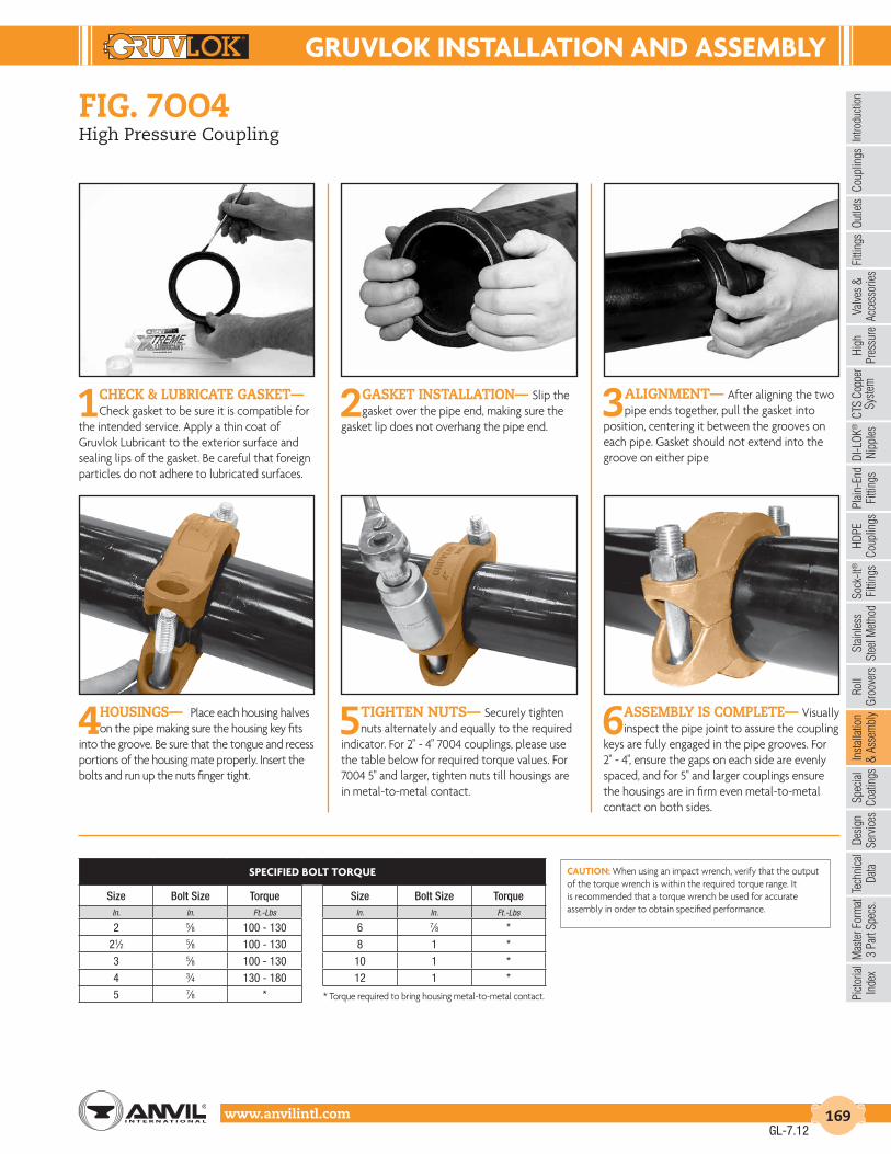
GruVLoK InStALLAtIon And ASSEMBLY
Intro
duct
ion
Coup
lings
Outle
tsFi
tting
sVa
lves
&
Acce
ssor
ies
High
Pres
sure
DI-L
OK®
Nipp
les
Plai
n-En
dFi
tting
sHD
PECo
uplin
gsSo
ck-It
®
Fitti
ngs
Stai
nles
sSt
eel M
etho
dRo
ll Gr
oove
rsIn
stal
latio
n&
Ass
embl
ySp
ecia
lCo
atin
gsDe
sign
Serv
ices
Tech
nica
lDa
taM
aste
r For
mat
3 Pa
rt Sp
ecs.
Pict
oria
lIn
dex
CTS
Copp
er
Syst
em
www.anvilintl.com 169
fiG. 7oo4High Pressure Coupling
1check & lubricate Gasket— Check gasket to be sure it is compatible for
the intended service. Apply a thin coat of Gruvlok Lubricant to the exterior surface and sealing lips of the gasket. Be careful that foreign particles do not adhere to lubricated surfaces.
2 Gasket installation— Slip the gasket over the pipe end, making sure the
gasket lip does not overhang the pipe end. 3 aliGnment— After aligning the two
pipe ends together, pull the gasket into position, centering it between the grooves on each pipe. Gasket should not extend into the groove on either pipe
4 housinGs— Place each housing halves on the pipe making sure the housing key fits
into the groove. Be sure that the tongue and recess portions of the housing mate properly. Insert the bolts and run up the nuts finger tight.
5 tiGhten nuts— Securely tighten nuts alternately and equally to the required
indicator. For 2" - 4" 7004 couplings, please use the table below for required torque values. For 7004 5" and larger, tighten nuts till housings are in metal-to-metal contact.
6 assembly is complete— Visually inspect the pipe joint to assure the coupling
keys are fully engaged in the pipe grooves. For 2" - 4", ensure the gaps on each side are evenly spaced, and for 5" and larger couplings ensure the housings are in firm even metal-to-metal contact on both sides.
cAutIon: When using an impact wrench, verify that the output of the torque wrench is within the required torque range. It is recommended that a torque wrench be used for accurate assembly in order to obtain specified performance.
SPEcIFIEd BoLt torQuE
Size Bolt Size Torque Size Bolt Size TorqueIn. In. Ft.-Lbs In. In. Ft.-Lbs
2 5⁄8 100 - 130 6 7⁄8 *
21⁄2 5⁄8 100 - 130 8 1 *
3 5⁄8 100 - 130 10 1 *
4 3⁄4 130 - 180 12 1 *
5 7⁄8 * * Torque required to bring housing metal-to-metal contact.
GL-7.12

GruVLoK InStALLAtIon And ASSEMBLY
www.anvilintl.com170
fiG. 7oo4 with eG® GasketHigh Pressure Coupling with End Guard® Gasket
1check & lubricate Gasket— Check gasket to be sure it is compatible for
the intended service. Apply a thin coat of Gruvlok Lubricant to the exterior surface and sealing lips of the gasket. Be careful that foreign particles do not adhere to lubricated surfaces.
2 Gasket & pipe installation— Slip the gasket half way on to the pipe end,
stop when the center gasket leg comes in contact with the pipe end. Slide the second pipe end half way into the gasket, stopping then the pipe end comes in contact with the center gasket leg. Ensure pipes are aligned properly.
3 housinGs— Place each housing halves on the pipe making sure the housing key fits
into the groove. Be sure that the tongue and recess portions of the housing mate properly. Insert the bolts and run up the nuts, finger tight.
4 tiGhten nuts— Securely tighten nuts alternately and equally to the required
indicator. For 2" - 4" couplings, please use the table below for required torque values. For 5" and larger, tighten nuts till housings are in firm metal-to-metal contact.
5 assembly is complete— Visually inspect the pipe joint to assure the coupling
keys are fully engaged in the pipe grooves. For 2" - 4", ensure the gaps on each side are evenly spaced, and for 5" and larger couplings ensure the housings are in firm even metal-to-metal contact on both sides.
cAutIon: When using an impact wrench, verify that the output of the torque wrench is within the required torque range. It is recommended that a torque wrench be used for accurate assembly in order to obtain specified performance.
SPEcIFIEd BoLt torQuE
Size Bolt Size Torque Size Bolt Size TorqueIn. In. Ft.-Lbs In. In. Ft.-Lbs
2 5⁄8 100 - 130 6 7⁄8 *
21⁄2 5⁄8 100 - 130 8 1 *
3 5⁄8 100 - 130 10 1 *
4 3⁄4 130 - 180 12 1 *
5 7⁄8 * * Torque required to bring housing metal-to-metal contact.
Figure 7004 with EG® gasket requires specified pipe end groove dimensions and fittings, see page 203 for groove dimensions.
cAutIon: Not using the correct groove dimensions will result in pipe joint separation. Pipe joint separation may result in significant property damage and serious injury.
GL-7.12

GruVLoK InStALLAtIon And ASSEMBLY
Intro
duct
ion
Coup
lings
Outle
tsFi
tting
sVa
lves
&
Acce
ssor
ies
High
Pres
sure
DI-L
OK®
Nipp
les
Plai
n-En
dFi
tting
sHD
PECo
uplin
gsSo
ck-It
®
Fitti
ngs
Stai
nles
sSt
eel M
etho
dRo
ll Gr
oove
rsIn
stal
latio
n&
Ass
embl
ySp
ecia
lCo
atin
gsDe
sign
Serv
ices
Tech
nica
lDa
taM
aste
r For
mat
3 Pa
rt Sp
ecs.
Pict
oria
lIn
dex
CTS
Copp
er
Syst
em
www.anvilintl.com 171
fiG. 7305HDPE Coupling
1Make certain the pipe ends are free of indentations, projections or other
imperfections, which could prevent proper sealing of the gasket. Mark each pipe at a distance from the end of the pipe according to the pipe size:
Size Inches Distance to Mark 2-4" (51 - 102 mm) 1" (25.4 mm) 5-8" (127 - 203 mm) 11⁄4" (31.8 mm) 10 & 12" (254 - 305 mm) 13⁄4" (44.5 mm)
NOTE: Make certain the HDPE pipe end is squarecut to 1⁄8" maximum for the 2" to 4" and 5⁄32" maximum for the 6" and larger sizes.
2 Check to assure the gasket material is acceptable for the intended service. The
Gasket color code is green for EPDM and orange for Nitrile (Buna-N). cAutIon: Use only Gruvlok XtremeTM Lubricant. Gruvlok XtremeTM Lubricant contains silicone. If silicone is unacceptable for the application contact Gruvlok for the lubrication recommendation. Apply a thin coating of Gruvlok XtremeTM Lubricant to the gasket lip and the exterior surface of the gasket.
3 Slip the gasket over one of the pipe ends. Make sure the gasket does not overhang
the pipe end. Align the second pipe and while keeping the pipes in the butted position slide the gasket back over the second pipe end. The gasket must be positioned centrally between the lines on the pipe ends.
4 Place the Figure 7305 housing casting over the gasket, making sure the tongue on one
casting is aligned with the recess of the other casting.
5 Insert the bolts and secure the nuts alternately and uniformly until the bolt
pads are in contact. Torque all bolts to the required bolt torque levels. Refer to the Specified Bolt Torque Table. There is no gap between the bolt pads and the bolt torque should be within the range given when the coupling is properly assembled. Alternate and even tightening of the bolts will significantly reduce the torque needed to close the gap at the pipe joint.
SPEcIFIEd BoLt torQuESpecified bolt torque is for the oval neck track bolts used on Gruvlok® couplings. The nuts must be tightened alternately and evenly until fully tightened. Caution: Use of an impact wrench is not recommended because the torque output can vary significantly due to many variables including air pressure supply, battery strength and operational variations.
CAUTION: Proper torquing of coupling bolts is required to obtain specified performance. Over torquing the bolts may result in damage to the bolt and/or casting which could result in pipe joint separation. Under torquing the bolts may result in lower pressure retention capabilities, lower bend load capabilities, joint leakage and pipe joint separation. Pipe joint separation may result in significant property damage and serious injury.
FIG. 7305 SPEcIFIEd BoLt torQuE
Coupling Bolts Minimum Maximum
In. Ft.-Lbs./N-m Ft.-Lbs./N-m
1⁄2 X 23⁄8 80 100110 150
1⁄2 X 3 80 100110 150
5⁄8 X 31⁄2 100 130135 175
3⁄4 X 43⁄4 130 180175 245
GL-7.12

GruVLoK InStALLAtIon And ASSEMBLY
www.anvilintl.com172
fiG. 7307HDPE Transition Coupling
1Make certain the HDPE pipe end is square cut to 1⁄8" maximum for the 2" to 4" and 5⁄32"
maximum for the 6" and larger sizes. The steel pipe must be grooved in accordance with Gruvlok® Grooving Specifications for Steel Pipe. The pipe ends must be free of scratches, indentations, projections or other imperfections, which could prevent proper sealing of the gasket.
2 Check to assure the gasket material is acceptable for the intended service. The
Gasket color code is green for EPDM and orange for Nitrile (Buna-N). cAutIon: Use only Gruvlok XtremeTM Lubricant. Gruvlok XtremeTM Lubricant contains silicone. If silicone is unacceptable for the application contact Gruvlok for the lubrication recommendation. Apply a thin coating of Gruvlok XtremeTM Lubricant to the gasket lips and the exterior surface of the gasket.
3 Slip the gasket over one of the pipe ends. Make sure the gasket does not overhang
the pipe end. Align the second pipe and while holding it in the butted position, slide the gasket back over the second pipe end. The gasket must be positioned on the gasket seat surface of the grooved steel pipe. Make sure the gasket does not overhang into the pipe groove.
4 Place each half of the coupling housing over the gasket, making sure the housing grooved
end is directed into the pipe groove.5 Insert the bolts and secure the nuts
alternately and uniformly until the bolt pads are in contact. Torque all bolts to the required bolt torque levels. Refer to the Specified Bolt Torque Table. There is no gap between the bolt pads and the bolt torque should be within the range given when the coupling is properly assembled. Alternate and even tightening of the bolts will significantly reduce the torque needed to close the gap at the pipe joint.
SPEcIFIEd BoLt torQuESpecified bolt torque is for the oval neck track bolts used on Gruvlok® couplings. The nuts must be tightened alternately and evenly until fully tightened. CAUTION: Use of an impact wrench is not recommended because the torque output can vary significantly due to many variables including air pressure supply, battery strength and operational variations.
cAutIon: Proper torquing of coupling bolts is required to obtain specified performance. Over torquing the bolts may result in damage to the bolt and/or casting which could result in pipe joint separation. Under torquing the bolts may result in lower pressure retention capabilities, lower bend load capabilities, joint leakage and pipe joint separation. Pipe joint separation may result in significant property damage and serious injury.
FIG. 7307 SPEcIFIEd BoLt torQuE
Coupling Bolts Minimum Maximum
In. Ft.-Lbs./N-m Ft.-Lbs./N-m
1⁄2 X 23⁄8 80 100110 150
1⁄2 X 3 80 100110 150
5⁄8 X 31⁄2 100 130135 175
7⁄8 X 51⁄2 180 220245 300
GL-7.12
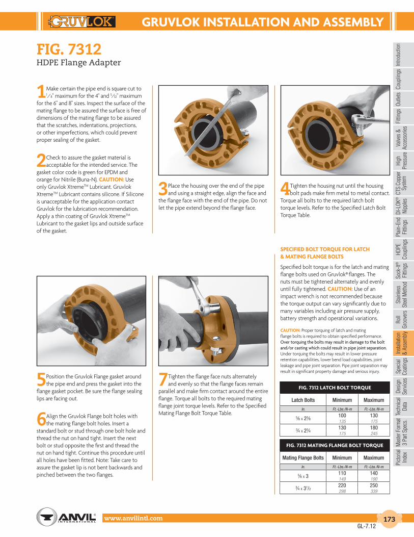
GruVLoK InStALLAtIon And ASSEMBLY
Intro
duct
ion
Coup
lings
Outle
tsFi
tting
sVa
lves
&
Acce
ssor
ies
High
Pres
sure
DI-L
OK®
Nipp
les
Plai
n-En
dFi
tting
sHD
PECo
uplin
gsSo
ck-It
®
Fitti
ngs
Stai
nles
sSt
eel M
etho
dRo
ll Gr
oove
rsIn
stal
latio
n&
Ass
embl
ySp
ecia
lCo
atin
gsDe
sign
Serv
ices
Tech
nica
lDa
taM
aste
r For
mat
3 Pa
rt Sp
ecs.
Pict
oria
lIn
dex
CTS
Copp
er
Syst
em
www.anvilintl.com 173
fiG. 7312HDPE Flange Adapter
1Make certain the pipe end is square cut to 1⁄8" maximum for the 4" and 5⁄32" maximum
for the 6" and 8" sizes. Inspect the surface of the mating flange to be assured the surface is free of dimensions of the mating flange to be assured that the scratches, indentations, projections, or other imperfections, which could prevent proper sealing of the gasket.
2 Check to assure the gasket material is acceptable for the intended service. The
gasket color code is green for EPDM and orange for Nitrile (Buna-N). cAutIon: Use only Gruvlok XtremeTM Lubricant. Gruvlok XtremeTM Lubricant contains silicone. If Silicone is unacceptable for the application contact Gruvlok for the lubrication recommendation. Apply a thin coating of Gruvlok XtremeTM Lubricant to the gasket lips and outside surface of the gasket.
3 Place the housing over the end of the pipe and using a straight edge, align the face and
the flange face with the end of the pipe. Do not let the pipe extend beyond the flange face.
4 Tighten the housing nut until the housing bolt pads make firm metal to metal contact.
Torque all bolts to the required latch bolt torque levels. Refer to the Specified Latch Bolt Torque Table.
5 Position the Gruvlok Flange gasket around the pipe end and press the gasket into the
flange gasket pocket. Be sure the flange sealing lips are facing out.
6Align the Gruvlok Flange bolt holes with the mating flange bolt holes. Insert a
standard bolt or stud through one bolt hole and thread the nut on hand tight. Insert the next bolt or stud opposite the first and thread the nut on hand tight. Continue this procedure until all holes have been fitted. Note: Take care to assure the gasket lip is not bent backwards and pinched between the two flanges.
7 Tighten the flange face nuts alternately and evenly so that the flange faces remain
parallel and make firm contact around the entire flange. Torque all bolts to the required mating flange joint torque levels. Refer to the Specified Mating Flange Bolt Torque Table.
SPEcIFIEd BoLt torQuE For LAtcH & MAtInG FLAnGE BoLtS
Specified bolt torque is for the latch and mating flange bolts used on Gruvlok® flanges. The nuts must be tightened alternately and evenly until fully tightened. cAutIon: Use of an impact wrench is not recommended because the torque output can vary significantly due to many variables including air pressure supply, battery strength and operational variations.
cAutIon: Proper torquing of latch and matingflange bolts is required to obtain specified performance.Over torquing the bolts may result in damage to the bolt and/or casting which could result in pipe joint separation. Under torquing the bolts may result in lower pressure retention capabilities, lower bend load capabilities, joint leakage and pipe joint separation. Pipe joint separation may result in significant property damage and serious injury.
FIG. 7312 LAtcH BoLt torQuE
Latch Bolts Minimum Maximum
In. Ft.-Lbs./N-m Ft.-Lbs./N-m
5⁄8 X 23⁄8 100 130135 175
3⁄4 X 23⁄4 130 180175 245
FIG. 7312 MAtInG FLAnGE BoLt torQuE
Mating Flange Bolts Minimum Maximum
In. Ft.-Lbs./N-m Ft.-Lbs./N-m
5⁄8 X 3 110 140149 190
3⁄4 X 31/2220 250298 339
GL-7.12

GruVLoK InStALLAtIon And ASSEMBLY
www.anvilintl.com174
1Pipe surface shall be cleaned at least 1" from the end of the pipe to remove any
coating, indentations, projections, and sharp edges which could affect proper gasket sealing. As a guide for installation, mark the pipe at a distance of 11⁄2" from the end for 1", 11⁄4", and 11⁄2" size fittings and 13⁄4" for the 2" & 21⁄2" size fittings.
notE: When Allied XL pipe is used it is necessary only to remove sharp edges and burrs at the end of the pipe. No additional cleaning is required.
2Check all lock bolts to be sure they do not extend into the I.D. of the Sock-It Fittings as
this would prevent proper insertion of the pipe.3Apply a light coating of GRUVLOK Lubricant
to the gaskets located in each end of the Sock-It Fitting. Also apply a light coating of lubricant to the pipe ends to further ease insertion of the pipe into the Sock-It Fitting.
notE: Use only Gruvlok Lubricants. Other lubricants may affect gasket performance.
4Insert the prepped and lubricated pipe end into the Sock-It Fitting until the pipe end makes contact with the internal pipe stop. A
slight twist while pushing fitting and pipe together will ease the required insertion force. The end of the Sock-It Fitting should be within 1⁄16" from the edge of the marking on the pipe. (See Step 1). Rotate the fitting until the desired position is obtained. Tighten the lock bolt until the bolt head bottoms against the threaded boss. (NOTE: The 21⁄2" Sock-It fitting has 2 locking bolts for each pipe end.)
Install the other prepped and lubricated pipe end into the Sock-It fitting in the same manner.
cAutIon: Do NOT hammer fitting on.
5Sock-It Fittings may be removed by loosening the lock bolts. Reinstallation may be accomplished as described in Steps 1-4.
WArnInG: System pressure must be relieved and vented, and the system drained of fluid prior to loosening the lock bolts to remove or reposition the Sock-It Fitting.
Bolt end must be inspected to assure bolts ability to cut into pipe. Replace bolts in cases where bolt end sharpness has been comprised.
Gruvlok sock-it® fitting
GL-6.11

GruVLoK InStALLAtIon And ASSEMBLY
Intro
duct
ion
Coup
lings
Outle
tsFi
tting
sVa
lves
&
Acce
ssor
ies
High
Pres
sure
DI-L
OK®
Nipp
les
Plai
n-En
dFi
tting
sHD
PECo
uplin
gsSo
ck-It
®
Fitti
ngs
Stai
nles
sSt
eel M
etho
dRo
ll Gr
oove
rsIn
stal
latio
n&
Ass
embl
ySp
ecia
lCo
atin
gsDe
sign
Serv
ices
Tech
nica
lDa
taM
aste
r For
mat
3 Pa
rt Sp
ecs.
Pict
oria
lIn
dex
CTS
Copp
er
Syst
em
www.anvilintl.com 175
ftv-s (straight) & ftv-a (angle body)Tri-Service Valve
installation:
1The valve should be mounted to a spool piece on the discharge side of the pump. Spool piece required is based on a minimum
recommended space of 12" for pump sizes 2" x 2" to 6" x 6" and 24" for pump sizes 8" x 8" to 12" x 12".
2 It is not recommended to mount a valve directly to the pump as this could cause undesirable noise in the system.
3 Sufficient clearance around the valve should be left for valve removal or repair.
4Install valve in the direction of the flow arrows on the valve body.
5The valve can be mounted to flanged equipment using Gruvlok Flange Adapter or industry standard grooved coupling, suitable for
system pressure and temperatures encountered.
6The Gruvlok Tri-Service valve bodies have anti-rotation lugs on the inlet and outlet. These lugs, combined with the Flange Adapters,
provide a ridged rotation free installation.
7The valve body has been designed to handle the weight of the pump on vertical in-line installations. The body is not designed to
support the piping weight. It is recommended that the piping be supported by hangers. Pipe supports should be provided under the valve and strainer bodies.
tYPIcAL InStALLAtIonS
Base-Mounted Single Suction Base-Mounted Double Suction Vertical In-Line
LEGENDGruvlok ductile iron flangeadapters for ANSI 150# flanges
Gruvlok ductile iron flangeadapters for ANSI 300# flanges
Grooved end with 375 psi ratedpipe coupling
AA B
C
Temperature° C
Temperature° FNote: for temperatures between 230°F and 300°F
(110°C and 149°C) specify Viton Elastomers.
Pres
sure
(psi
)
Pres
sure
(kpa
)
400-46° -29° -18° 10° 38° 66° 93° 110°
-50° -20° -0° 50° 100° 150° 200° 230°
375
300250200
100
0
2,7602,585
2,0701,7241,380
690
250
B & C
pressure – temperature limitsfield conversion(straight to angle pattern valve)
1Open valve at least one complete turn,
2Remove the body bolts from valve body using Allen Key.
3Rotate one half of the valve body 180° making sure the lower valve seat and “O”
Ring stay in position. Inspect the “O” Ring for any cuts or nicks and replace if necessary.
4Replace body bolts and torque evenly to 70 ft./lbs.
flow measurement
Where approximate indication of flow is acceptable the Gruvlok Tri-Service valve can be used.
flow measurement valve in wide open position
Measure and record the differential pressure across the valve using a Flow Meter with high pressure range transducer or pressure gauges with PMP adapters.
Refer to Tri-Service Performance Curves with valve in full open position (See Determining Flow Rate with Valve in Throttled Position Section on page 177). Locate Pressure Differential on left hand side of chart and extend line horizontally across to valve size being used. Drop line vertically down and read flow rate from bottom of chart.
cAutIon:Safety glasses should be used and the probe should not be left inserted into fittings for prolonged periods of time (overnight, etc.), as leakage from the PMP may occur when probe is removed.
GL-6.11

GruVLoK InStALLAtIon And ASSEMBLY
www.anvilintl.com176
7Tighten the nuts evenly so that the flange faces
remain parallel and make firm even contact around the entire flange. Torque all bolts to required flange joint torque levels.
5The correct positioning and relationship of all components
comprising a Gruvlok Flange joint. The Fig. 7012 Gruvlok Flange gasket must be inserted so that the sealing lips face toward the pipe end and the mating flange face and away from the Gruvlok Flange itself.
NOTE: Design of the Gruvlok Flange provides sealing only with the special Gruvlok Flange gasket. Only Gruvlok Flange gaskets may be used with Fig. 7012 Gruvlok Flanges.
Proper positionof gasket sealing lips
Gasket
Flange,pump,tank, valve, etc.
GruvlokFlange
GroovedPipe
flanGe adapter installation:
1The Fig. 7012 Gruvlok Flange Adaptercan be used with the FTV Tri-Service
Valve. Installation is similar to theinstallation of the Figure 7012 withgrooved pipe.
ftv-s (straight) & ftv-a (angle body)Tri-Service Valve
2Loosen the nut on the latch bolt to the end of the bolt
thread. (It is not necessary to remove the nut from the latch bolt.) Swing the latch bolt out of the slot. Open the Gruvlok Flange and place it around the grooved pipe with the key section fitting into the groove. The flange gasket cavity must face the pipe end.
3Swing the latch bolt back into the slotted hole.
Tighten the nut until the flange halves make solid contact.
4Check the gasket grade to verify that it is properly
suited for the intended service. Lubricate the entire surface of the gasket and the flange gasket cavity using Gruvlok lubricant. Position the Gruvlok Flange Gasket around the pipe end and press the gasket into the cavity between the pipe O.D. and the flange recess. The gasket must be properly positioned as shown in Step 5. Be careful that foreign particles do not adhere to lubricated surfaces.
6Align the Gruvlok Flange bolt holes with the mating
flange bolt holes. Insert a standard bolt or stud through the bolt hole, and thread a nut on hand tight. Insert the next bolt or stud opposite the first and again thread the nut on hand tight. Continue this procedure until all holes have been fitted. (See illustration)
NOTE: Take care to assure that the gasket lip is not bent backwards or pinched between the two flanges.
1START
Recommended Bolt Tightening Sequence
1611
8
3
13
10
5
2
7
4
14
9
6
1512
GL-7.12

GruVLoK InStALLAtIon And ASSEMBLY
Intro
duct
ion
Coup
lings
Outle
tsFi
tting
sVa
lves
&
Acce
ssor
ies
High
Pres
sure
DI-L
OK®
Nipp
les
Plai
n-En
dFi
tting
sHD
PECo
uplin
gsSo
ck-It
®
Fitti
ngs
Stai
nles
sSt
eel M
etho
dRo
ll Gr
oove
rsIn
stal
latio
n&
Ass
embl
ySp
ecia
lCo
atin
gsDe
sign
Serv
ices
Tech
nica
lDa
taM
aste
r For
mat
3 Pa
rt Sp
ecs.
Pict
oria
lIn
dex
CTS
Copp
er
Syst
em
www.anvilintl.com 177
ftv-s (straight) & ftv-a (angle body)Tri-Service Valve
00
20
2.0
5.0
50
3.0
.5
1
3
5
5.0 10 20 50 100 200 400FLOWRATE (L/SEC)
PRES
SUR
E D
RO
P (M
H2O
)
PRES
SUR
E D
RO
P (F
T. W
G)
FLOWRATE (US GAL/MIN)100 500 1000 2000 4000 6000
10
20
2.0
5.0
10
20
20
40
40
60
60
8012"
6"
2"21/2"
6"
5"
8"
10"
3"4"
21/2"
80
100
100PERCENT OF FULL OPEN
Inherent Flow Characteristic Curvewith Valve in Throttled Position
Tri-Service Performance Curvewith Valve in Full Open Position
PER
CEN
T O
F M
AX F
LOW
4"5"
8"10"
12"
determininG flow rate with valve in throttled position:
1Record the size of valve and stem position using the Flow Indicator Scale (See Flow Indicator Section at bottom of page). Calculate
percentage of valve opening referring to table below:
2Measure and record the differential pressure across the valve in the throttled position.
3Locate percentage of valve opening on the bottom scale of Flow Characteristic Curve. Project line vertically up to intersect with the
Valve Characteristic Curve and from this point project line horizontally across to the left of the chart and record the percentage of maximum flow rate.
4On the Tri-Service Performance Curve locate the differential pressure obtained in Step 2 and project line horizontally across to
intercept with Valve Performance Curve. Drop a line vertically down to read the flow rate at the bottom of the chart.
VALVE SIZE 21/2 3 4 5 6 8 10 12
Number of Rings(valve full open)
5 5 6 9 10 12 18 28
5To calculate flow rate of valve in the throttled position, multiply the flow rate from Step 4 by the percentage flow rate from Step 2
divided by 100.
Example: Valve size 4 in. Differential Pressure in 5.4 ft. (1.65 m) Number of rings open 3, (3 rings / 6 rings X 100) = 50% throttle
Solution: • From the Tri-Service Performance Curve (fig. 5), a 4 in. valve with 5.4 ft. pressure drop (1.65 m) represents a flow of 400 USgpm (25.2 L/s).
• From Flow Characteristic Curve (fig, 6), a 4 in. valve, 50% open, represents 34% of maximum flow.
• Approximate flow of a 4 in. valve, with a 5.4 ft. ( 1.65 m) pressure drop when 50% throttled is: (400 x 34)/100 = 136 USgpm (25.2 x 34)/100 = 8.57 L/sec.
Note: To prevent premature valve failure it is not recommended that the valve operate in the throttled position with more than 25 ft. pressure differential. Instead the pump impeller should be trimmed or valves located elsewhere in the system to partially throttle the flow.
00
20
2.0
5.0
50
3.0
.5
1
3
5
5.0 10 20 50 100 200 400FLOWRATE (L/SEC)
PRES
SUR
E D
RO
P (M
H2O
)
PRES
SUR
E D
RO
P (F
T. W
G)
FLOWRATE (US GAL/MIN)100 500 1000 2000 4000 6000
10
20
2.0
5.0
10
20
20
40
40
60
60
8012"
6"
2"21/2"
6"
5"
8"
10"
3"4"
21/2"
80
100
100PERCENT OF FULL OPEN
Inherent Flow Characteristic Curvewith Valve in Throttled Position
Tri-Service Performance Curvewith Valve in Full Open Position
PER
CEN
T O
F M
AX F
LOW
4"5"
8"10"
12"
flow indicator scale
The valve stem with its grooved rings and positioning sleeve indicates the throttled position of the valve. The quarter turn graduations on the sleeve, with the scribed line on the stem, provide for approximate flow measurement.
Note: The valve is shipped in the closed position. The indicator on the plastic sleeve is aligned with the vertical scribed line on the stem.
Scribed Lines
GL-6.11

GruVLoK InStALLAtIon And ASSEMBLY
www.anvilintl.com178
ftv-s (straight) & ftv-a (angle body)Tri-Service Valve
operation
To assure tight shut off the valve must be closed using a wrench with 25 to 30 ft./lbs of torque.
To assure trouble-free check valve operation and shut off operation, the valve should be periodically opened and closed to keep valve seat and valve disc guide stem free of build up of system contaminants.
repackinG of ftv valve under full system pressure
Should it be necessary, stem “O” Ring can be changed under full system pressure.
1Record the valve setting.
2 Turn the valve stem counterclockwise until the valve is fully open and will not turn any further. Torque to a maximum force of 45 ft./lbs.
This will ensure good metal-to-metal contact and minimum leakage.
3The valve bonnet may now be removed. There may be a slight leakage, as the metal-to-metal backseating does not provide a
drip-tight seal.
4Clean exposed portion of valve stem (Do not scratch).
5Remove and replace the “O” Ring and gasket.
6Install the valve bonnet.
7Tightening valve bonnet is necessary to stop any leaks.
8Open valve to balance set point as recorded in Step 1.
cAutIon: Safety glasses should be worn.
maximum number of turns full open valve
On valve sizes 21/2" and 3", full open position of valve is 5 turns. However, valve will open to 51/2 turns which is just back of seating of valve.
seat replacement
1Drain system and remove valve from piping.
2Remove the body bolts from the body using an Allen Key.
3Remove seat and “O” Ring. “O” Ring is not used on valves 8" and larger.
4Clean exposed portion of valve stem (Do not scratch).
5Remove and replace the “O” Ring and gasket.
6Inspect and clean “O” Ring cavity and install new “O” Ring and seat. Valve disc stem also should be inspected and replaced if worn.
Valve stem “O” Ring should be replaced at this time.
GL-6.11

GruVLoK InStALLAtIon And ASSEMBLY
Intro
duct
ion
Coup
lings
Outle
tsFi
tting
sVa
lves
&
Acce
ssor
ies
High
Pres
sure
DI-L
OK®
Nipp
les
Plai
n-En
dFi
tting
sHD
PECo
uplin
gsSo
ck-It
®
Fitti
ngs
Stai
nles
sSt
eel M
etho
dRo
ll Gr
oove
rsIn
stal
latio
n&
Ass
embl
ySp
ecia
lCo
atin
gsDe
sign
Serv
ices
Tech
nica
lDa
taM
aste
r For
mat
3 Pa
rt Sp
ecs.
Pict
oria
lIn
dex
CTS
Copp
er
Syst
em
www.anvilintl.com 179
fiG. Gbv-s & Gbv-tFive Turn Circuit Balancing Valves
installation:
1 Clean the system piping of debris (pipe scale, rust, welding slag) and other
contaminants. As with any water system it is important to make provisions to keep the system clean. For optimum operation, air entrapment in the fluid must be removed.
2 The operation of the valve is dependent on the fluid characteristics such as specific
gravity and viscosity, which vary with the fluid temperature. For installations using fluids other than 100% water, flow rates must be corrected for the changes created by the fluid medium. See www. anvilintl.com for appropriate correction factors, or call your local Anvil representative.
3 To ensure accuracy of measurement Circuit Balancing Valves (GBV’s) should be located
at least five pipe diameters downstream from any fitting and at least ten pipe diameters downstream from a pump (as illustrated in Fig. 1).
4 All GBV’s are marked with an arrow on the valve body to indicate direction of flow.
The arrow must point in the direction of flow for proper operation.
5 GBV’s may be installed in horizontal or vertical piping (as illustrated in Fig. 2).
Provisions must be made for easy access to the probe metering ports (P.M.P.’s), reading scale, and memory stop.
Gbv-s - sweat (solder) connections:
6 GBV-S models are supplied with sweat style connections. Caution should be used when
sweat style connection valves are installed to prevent overheating the valve.
7 Solder the valve body in line using 95/5 (95% tin, 5% antimony) type solder or
equal. Always follow local plumbing codes for installation best practices.
Gbv-t - npt threaded connections
6 GBV-T models are tapped with NPT threaded connections. All threaded
connections should be sealed using an approved pipe sealant per industry standards. Once the GBV installation has been completed and the system has been filled and purged, each valve loop must be adjusted to the correct flow setting. Employ piping best practice when engaging pipe to threaded valves. Overtightening when installing valves may result in fracturing of the valve body at the threads. (Go to Step 8)
operation:
8 Valves are circuit balancing valves that are selected to deliver the correct flow in a
piping circuit based on line size and design flow rate.
9 To set the system flow, adjust the handwheel position until the differential
pressure reading across the venturi corresponds to the required GPM.
10 The valve operates from fully open to closed by a clockwise rotation of the
orange handwheel using five 360° turns. Two indicators describe the position of the valve: the handwheel turns dial and the micrometer scale.
• “Handwheel turns” dial: This dial is printed on the outer surface of a gearing mechanism located inside the lower half of the handle assembly (Fig. 6). Each complete 360° revolution of the handwheel is visible through a display window and is scaled 0 - 5 to indicate the valve position in terms of the number of full turns. (Fig. 3)
• Micrometer Scale: This scale is marked 0 - 9 and is located on the upper half of the handle assembly. Each mark represents 1⁄10
th of a full, 360° turn of opening when lined up with an arrowhead symbol, located above the handwheel turns display window. (Fig. 3)
cAutIon:Before soldering, ensure the valve is opened at least one full turn to avoid damage to the sealing O-ring due to overheating. Anvil recommends that the GBV be protected during installation by wrapping a damp rag around the handle / bonnet assembly prior to soldering the valve into the line.
WArnInG:Anvil does NOT recommend leak testing an HVAC system with air due to safety concerns. Testing HVAC systems with pressurized air can be dangerous due to the high compressibility of air, as compared to water.
11 The valve is considered “zeroed” when fully closed hand tight. The “0” on the
micrometer scale should be within one half of 1⁄10th of a turn of the arrowhead symbol when the valve is closed hand tight. DO NOT USE A WRENCH ON THESE VALVES – THEY SHOULD BE OPENED AND CLOSED HAND-TIGHT ONLY!
GBV GBV
fig. 1
fig. 2
SCALE
DIAL
Fig. 3: GBV setting of 0.0 indicates that the valve is closed. Both the handwheel turns dial and the micrometer scale indicate a valve position reading of 0.
Fig. 4: GBV settingof 2.3 indicates that the valve is partially open (2.3 turns open).
GL-6.11

GruVLoK InStALLAtIon And ASSEMBLY
www.anvilintl.com180
Venturi Cv Performance Curve s
cAutIon: Hot water leakage can occur frommetering ports (P.M.P.’s) during probe insertionand hookup of metering device. Wear protectiveeyewear and clothing to prevent personal injurywhen measuring pressure.
Fig. 5: GBV setting of5.0 indicates that thevalve is fully opened.In some cases, the valvemay open as much as 5.3 turns, due to the depthof the stem threads. This is not a problem with the valve; however, the performance curves for these GBVs are calibrated only to 5.0 turns.
12 Connect pressure measuring device to the GBV metering ports as follows:
• Remove protective cap from metering ports (1⁄4" NPT connection).
• Insert the meter probe into the metering ports. The hose with orange fitting, up stream; the hose with blue fitting downstream.
cAutIon:
When inserting probe, do not bend, as this will cause permanent damage to the probe, adversely affecting the pressure measurement. Do not use any lubrication on the probes when inserting them. If necessary, simply wet the probes with clean water.
The probe should not be left inserted into the fitting for prolonged periods of time, overnight, etc., as leakage of the P.M.P. may occur when the probe is removed.
The locking nut on the probe is designed to hold it in the P.M.P. when taking readings. As sealing is accomplished internally on the probe stem, it is only necessary to tighten the locking nut FINGER-TIGHT. Over-tightening may cause damage to the P.M.P. or locking nut threads.
13 Before taking a measurement reading, set the valve to its fully open position
(5.0) or at a preset position. Read the pressure drop across the venturi with a digital meter. Determine flow rate by use of venturi Cv performance curves on page 4 or the Anvil Balancing Slide Rule.
14 The handle of the GBV is not designed to be removable. Do not try to take it
off the valve, or it may become damaged. If for any reason, the handle is damaged, replace the entire handle assembly with the appropriate replacement part indicated in the table below.
memory settinG:
15 After valve has been properly adjusted and without moving the handwheel,
the locking memory stop should be set. The memory stop will allow the valve to be fully closed for isolation and then reopened to the preset flow position.
16 Insert a 2.5 mm (or 3⁄32") Allen key through the hole provided in the valve’s
handle cap. (Fig. 6)
17 Turn the setscrew in a clockwise direction until it stops. It is not
necessary to tighten. The memory has now been set. This establishes the maximum opening position for this particular valve.
18 The valve may now be closed tightly, as needed, for isolating the piping
during system maintenance. To return the valve to its preset “balanced” position, simply open the valve by turning the handwheel counter-clockwise until the handle stops turning (the valve stem inside the handle has hit the memory setscrew). DO NOT APPLY EXCESSIVE FORCE WHEN REOPENING THE VALVE – OPEN ONLY UNTIL THE VALVE STOPS TURNING UNDER “HAND TIGHT” CONDITIONS. DO NOT USE A WRENCH TO OPEN, CLOSE, OR TIGHTEN VALVES.
See next page for Fig. 8 for both the GBV-S & GBV-T and a troubleshooting chart
Fig. 7: These curves are for balancing contractors’ use when balancing an HVAC system. For pressure drop vs. flow across the entire valve, please refer to Fig. 8.
fiG. Gbv-s & Gbv-tFive Turn Circuit Balancing Valves
HANDWHEEL
LOCK NUTSET SCREW
CAP
TURNINDICATOR
STEM
High Pressure Port (orange)
Low Pressure Port (blue)
fig. 6
PArt nuMBEr SIZE
571155-022 1⁄2"571155-022 3⁄4"571155-022 1"571155-022 11⁄4"571155-022 11⁄2"571155-022 2"
GL-7.12

GruVLoK InStALLAtIon And ASSEMBLY
Intro
duct
ion
Coup
lings
Outle
tsFi
tting
sVa
lves
&
Acce
ssor
ies
High
Pres
sure
DI-L
OK®
Nipp
les
Plai
n-En
dFi
tting
sHD
PECo
uplin
gsSo
ck-It
®
Fitti
ngs
Stai
nles
sSt
eel M
etho
dRo
ll Gr
oove
rsIn
stal
latio
n&
Ass
embl
ySp
ecia
lCo
atin
gsDe
sign
Serv
ices
Tech
nica
lDa
taM
aste
r For
mat
3 Pa
rt Sp
ecs.
Pict
oria
lIn
dex
CTS
Copp
er
Syst
em
www.anvilintl.com 181
GBV -T
GBV -S
fiG. Gbv-s & Gbv-tFive Turn Circuit Balancing Valves
trouBLESHootInG:
Symptom Likely cause Solution
1. Valve is leaking:
• At the bonnet / body joint Bonnet o-ring has been damaged. Remove the handle / stem assembly and replace with the appropriate replacement part indicated in Table 1.
• At the pipe connection If solder joint - the joint has failed, or was not soldered properly.
Re-solder the connection and recheck for leakage.
If threaded - the connection is not sufficiently tight, or Tighten and re-check for leakage.
the valve was over-tightened during installation and the valve body has cracked (fractured).
Remove and reinstall a new valve, being careful not to over-tighten.
2. Valve does not shut off completely when closed (hand tight).
The seat o-ring has been deformed due to overheating during soldering.
Remove the handle / stem assembly and replace with the appropriate replacement part indicated in Table 1.
Fig. 8: These curvesshow the pressure dropacross the balancing valvesand are for use in valvesizing. For “pressure drop /flow” curves – required forsystem balancing, pleaserefer to Fig. 7.
Fig. 8: These curves show thepressure drop across thebalancing valves and are for usein valve sizing. For “pressuredrop / flow” curves – requiredfor system balancing, pleaserefer to Fig. 7.
GL-7.12

GruVLoK InStALLAtIon And ASSEMBLY
www.anvilintl.com182
installation
1Avoid torque. Do not twist the hose assembly during installation when aligning
the bolt holes in a flange or in making up pipe threads. The utilization of lap joint flanges or pipe unions will minimize this condition.
2 To install a thread end braided metal hose assembly unions must be used. Do not
place wrenches on the braided portion or the collar of the braided metal hose assembly. Use care not to torque the braided metal hose assembly while tightening the union. It is recommended that two wrenches be used in making the union connection; one to prevent the hose from twisting and the other to tighten the coupling.
3 Install the braided metal hose assembly with neutral face-to-face dimension as
shown on the submittal drawing. Do not install a braided metal hose assembly compressed (bagged braid). The corrugated inner hose contains the fluid, the braid is designed to take the stress of system pressurization and contain the core.
4 If the braided metal hose assembly must be installed with an initial offset then the
maximum allowable movement is reduced by the amount of the initial deflection.
5 Avoid over bending. The repetitive bending of a hose assembly to a radius smaller than
the radius specified will result in early hose failure. Always provide sufficient length to prevent over bending and to eliminate strain on the hose assembly. Utilize sound geometric configurations that avoid sharp bends, especially near the end fittings of the assembly.
6 Verify that the movements of the system are within the design parameters of the
braided metal hose assembly being installed.
7 Prevent out-of-plane flexing in an installation. Always install the hose
assembly so that the flexing takes place in only one plane—this being the plane in which the bending occurs.
8 The maximum system test pressure must not exceed 150% of the maximum rated
working pressure as shown.
9 Check system pressure and temperature and do not exceed recommended performance
limits. Operation beyond design limits will result in premature failure.
anvilflex™ fiG. af21-GG, -Gf & -ffFlex Connectors
10 The corrugated metal hose alloy must be chemically compatible with the
media in the piping system. If in doubt as to suitability, refer to a Chemical Resistance Data table or contact your Anvil rep. for guidance.
11 The flanges on a concentric increasing braided metal hose assembly have
the bolt holes straddling the hose centerline. The mating flanges should also straddle the centerline to avoid torque on the braided metal hose assembly.
12 When installing weld end, or sweat end, braided metal hose assemblies, or when
welding in the area of a braided metal hose assembly, extreme care is necessary in ensure no weld spatter comes in contact with the braided hose sections.
13 A piping system, which utilizes braided metal hose to absorb movement, must
be properly anchored and/or guided. Always support the piping to prevent excessive weight from compressing the hose and relaxing the braid tension.
14 Use care when handling the braided metal hose assembly during
transportation, storage, and installation. The braided hose sections must not be allowed to bend, deflect, sag, or otherwise extend beyond their rated capabilities.
15 The shipping sticks, on flanged units, are to keep the braided metal
hose assembly in its neutral end-to-end dimension during shipping and installation. After installation, the shipping sticks should be removed.
maintenance
1 The braided metal hose assembly should be inspected during routine maintenance
to ensure there are no signs of external damage. Inspect for frayed or broken braid wires. Also inspect to ensure there is no damage to the hose. In the event that such damage is found, the braided metal hose assembly should be replaced.
2 During system shutdown braided metal hose assembly should be examined to verify
no thermal axial motion has occurred causing compression of the assembly.
Groove x GrooveProper Installation
Groove x GrooveImproper Installation
Parallel
Groove x GrooveImproper Installation
Compressed
GL-6.11

AnVIL SPEcIAL coAtInGS
Intro
duct
ion
Coup
lings
Outle
tsFi
tting
sVa
lves
&
Acce
ssor
ies
High
Pres
sure
DI-L
OK®
Nipp
les
Plai
n-En
dFi
tting
sHD
PECo
uplin
gsSo
ck-It
®
Fitti
ngs
Stai
nles
sSt
eel M
etho
dRo
ll Gr
oove
rsIn
stal
latio
n&
Ass
embl
ySp
ecia
lCo
atin
gsDe
sign
Serv
ices
Tech
nica
lDa
taM
aste
r For
mat
3 Pa
rt Sp
ecs.
Pict
oria
lIn
dex
CTS
Copp
er
Syst
em
www.anvilintl.com 183
protect your products and your investment with anvil coatinGs.Did you know that Anvil can provide you with significant
cost-savings for your underground piping applications?
Your drilling or recovery efforts stir up, push down and release corrosive chemicals that attack your piping products, destroying their performance— and your investment.
Anvil’s field-proven, cost-effective coatings are designed to protect all grades of Malleable, Cast Iron, Forged Steel and Ductile piping products against a wide range of environmental concerns, including soil stress, soil acids, bacteria and fungus, and alkalis. Our coatings include:
• Scotchcote 134 — A fusion bonded epoxy coating designed to resist wastewater, corrosive soils, hydrocarbons, harsh chemicals, brine and saltwater.
• corvel 1660 — Specially designed to protect the inside diameter of tubular goods from corrosive conditions such as H2S, CO2, harsh chemicals, brine and saltwater.
• Additional coatings — We offer other coatings as well, including: Nickel, Chrome, Teflon, Nap-Guard, Powder and many more.
Let us help you prolong your piping product investment and save you money.
did you know...Anvil International is the only manufacturer to stock, offer and warranty coated piping product solutions.
Anvil’s protective coatings are ideal for both internal and external applications, including:
• Natural Gas
• Petroleum
• Water and Sewage
• Refineries
• Petrochemical Plants
• Power Plants
• Paper Mills
GL-6.11

dESIGn SErVIcES
www.anvilintl.com184
anvil desiGn servicesoffers both Basic and Extended Services...
Contact your Anvil representative for more information.
BASIc SErVIcESAnvil Design Services produces fabrication drawings of mechanical room piping 21⁄2" and larger including chillers, heat exchangers, boilers, and pumps from contractor supplied flow diagrams, mechanical drawings, and approved submittals and specifications.
The drawings include a Bill of Materials with tags referencing the components in the mechanical room. The piping is color coded by service and is represented in 3-D with plan, isometric, and elevation views.
Initially, Anvil personnel meet with you to determine your piping preferences. The project scope and fee is agreed upon in a Design Services contract.
The plans and specifications are then interpreted in terms of economy, accuracy, and compliance. We may suggest modifications in arrangement, construction, equipment location, or product to attain the desired results. Piping layouts are carefully analyzed to determine whether further economies can be attained in the piping system.
Piping drawings are then prepared to determine the most efficient pipe routing, taking equipment location and any interferences into consideration. Preliminary prints are sent to you for revision or approval.
Upon approval, (4) sets of drawings with tags and Bills of Materials of the included system components are sent to you. Copies of the electronic data file of the project drawings are available at no extra charge. This brochure is an example of the finished product.
With Basic Services, you can plan the mechanical room. The preliminary drawings can be taken to coordination meetings with other trades to “reserve” space by “getting in” first. Also, your field supervisor can spend more time supervising and not calculating pipe lengths and pipe routing. The components can be grouped from the finished drawings for better workflow planning.
We usually reduce fitting counts by 10%-15% by moving equipment whenever possible, usually less than a foot. The more movement that is allowed, the more savings can be realized.
EXtEndEd SErVIcES:Extended Services include any scope beyond Basic Services. There are many different types of services offered as extended:• BOM by component (pump, chiller) or by system• Unique Tagging – adding unique tags to individual components• Air Handling Units – with associated ductwork• Single Line Routing – non-dimensional• Distribution Piping• Dimensioned Floor Penetrations• AWWA Piping - Total Scope• Commercial Piping• Oil Field Piping• Retrofit Projects - Field Survey• Hybrid Systems• Anything Else
contact your Anvil representative for more information.
GL-6.11

dESIGn SErVIcES
Intro
duct
ion
Coup
lings
Outle
tsFi
tting
sVa
lves
&
Acce
ssor
ies
High
Pres
sure
DI-L
OK®
Nipp
les
Plai
n-En
dFi
tting
sHD
PECo
uplin
gsSo
ck-It
®
Fitti
ngs
Stai
nles
sSt
eel M
etho
dRo
ll Gr
oove
rsIn
stal
latio
n&
Ass
embl
ySp
ecia
lCo
atin
gsDe
sign
Serv
ices
Tech
nica
lDa
taM
aste
r For
mat
3 Pa
rt Sp
ecs.
Pict
oria
lIn
dex
CTS
Copp
er
Syst
em
www.anvilintl.com 185
1'-2 1/2" 2'-4 11/16"
3'-8 15/16" 3'-10 11/16"
5'-4 9/16" 6'-8 3/4"
7'-8 7/8" 8'-3"
10'-3 3/4" 16'-3 15/16"
17'-8 1/16" 19'-7 13/16"
23'-2 7/16" 24'-6 9/16"
26'-6 5/16"
6'-11 1/8"
6'-8 7/8"
5'-5 3/16"
C ELE V. 10'-0" L
" 8 / 5 7 - ' 5 " 8 / 7 1 - ' 7
" 8 / 7 1 - ' 8 " 8 / 1 0 - ' 9
" 8 / 3 4 - ' 0 1 " 8 / 3 0 1 - ' 2 1
" 2 / 1 0 - ' 4 1 " 2 / 1 4 - ' 0 2
" 2 / 1 2 - ' 4 2 " 5 - ' 6 2
" 2 / 1 1 1 - ' 7 2 " 7 - ' 8 2
" 2 / 1 7 - ' 1 3 " 0 1 - ' 7 3
" 7 - ' 2 1 " 8 / 5 6 - ' 3 1
" 6 1 / 5 1 0 1 - ' 3 1
54
59
54
59
54
32
58 32
32 38
54
61
2 5
5
16
60
54
54
33 32
49 32
36 32 65
62
54
60 54 59 54 65 32 36
32 33
32 45
32 33
32
32 66
54 59
54 60
54
48
51 7
35
50
72
52
51 10
7
7 54
55 56
18
7 10 7
17
5
2 5
15
1 22 21
26 5 7 8
7
14
12 7
11
2 8
7 10
7
11 12 7
5 8 5
5 4 7
2 3
3
2 7 4 5
2 5
22 21 26
5 9 7 10
7 8 2 7
2 7
12 11
14
8 7
12 11 20
57
56
54
53
54
32
33
32
71 46
47 57
54
55
54
59 54
66 32
69
32
36 36
32
69
66
66
54
59
54
70
54
54 66
32
79
32
36
36
32 42
32
33
32
36 32 43 32
33 32
70
L C ELE V. 10'-0"
C ELE V. 11'-0" L
C ELE V. 11'-0" L
C ELE V. 10'-0" L
C ELEV . 8'-1 5/8" L
C ELEV . 8'-6 1/8" L
C ELEV . 8'-6 1/8" L
C ELEV . 10'-0" L
L C ELEV . 10'-0"
HX-2 HX-1
P-4
P-3
P-2
P-1
B-1 B-2
A
M- 1
PIPING PLAN VIEW
3/8" = 1'-0"
C
M- 2
B
M-2
D
M-2
290390014249 90 ELBO W, GRVD GRUVLOK,Fig.7050 2 2.5 10
55 10 2
4 1 12
6 10 6
81 61 58
60 10 3
T AG#
VA LV ES Qty
2 2 8
8
2 2
2 2
2 2
5 1
24 2 2
SIZE
2.5 2.5 2.5
27 25 4
6
6
90
89 6x5
6x4 4
6x5 5
85
84 83
87 86
10x6 10
6 6 6
66 62
80 76 75
4
2 22 2
7 2
73 8 18
4
6 2 4
6 2
32 27
4 4 6
28 2.5
10x2.5 51
10 10
10x6 10
56 54
59 57
6 6
6
6
33 32
36
34
2.5x2
4x2.5 2.5 2 2
21 19 12
26 23
2.5 2.5
2.5 4
2.5 7 5
11 10 8
GRUVLOK,SER.7700 BUTTERF LY VA L VE, GRVD
BUTTERF LY VA L VE, GRVD BUTTERF LY VA L VE, GRVD
3DTY VA L VE, GROOVED GRUVLOK,FIG.722G GRUVLOK,SER.7700 GRUVLOK,SER.7700
COUPLING, FLEX GRVD. COUPLING, RIGIDLOK GRVD.
COUPLING, RIGIDLOK GRVD. 4x2.5" GRVD CONC REDUCER
2.5x2" GRVD CONC REDUCER GRVD. FLANGE ADAP T. COUPLING, RIGIDLOK GRVD.
STRAINER, GROOVED
COUPLING, RIGIDLOK GRVD. GRVD. FLANGE ADAP T.
REDUCING TEE, GROOVED
10x6" GRVD CONC REDUCER
COUPLING, FLEX GRVD. GRVD. FLANGE ADAP T. 6x4" GRVD CONC REDUCER
SUCTION DIFF , GROOVED
GRVD. FLANGE ADAP T. 6x5" GRVD CONC REDUCER
SUCTION DIFF , GROOVED
GRVD. FLANGE ADAP T.
CHECK VA L VE, GRVD
BUTTERF LY VA L VE, GRVD DESCRIPTION #1
STRAINER, GROOVED
90 ELBO W, GRVD GRUVLOK,Fig.7050
GRUVLOK,Fig.7012
GRUVLOK,Fig.7250
GRUVLOK,SER.7800 GRUVLOK,FIG.758 GRUVLOK,SER.7700 PA R T#
GRUVLOK,Fig.7072 GRUVLOK,Fig.7060
GRUVLOK,Fig.7072 GRUVLOK,Fig.7012
GRUVLOK,Fig.7250
GRUVLOK,Fig.7072 GRUVLOK,Fig.7012 GRUVLOK,Fig.7001 GRUVLOK,Fig.7060 GRUVLOK,Fig.7074
TEE, GROOVED
TEE, GROOVED CA P, GRVD
GRUVLOK,Fig.7012
GRUVLOK,Fig.7051LR GRUVLOK,Fig.7401
GRUVLOK,Fig.7061 GRUVLOK,Fig.7051LR GRUVLOK,Fig.7012 GRUVLOK,Fig.7401
GRUVLOK,Fig.7050
GRUVLOK,Fig.7260
GRUVLOK,Fig.7401 GRUVLOK,Fig.7001
GRUVLOK,Fig.7076
GRUVLOK,Fig.7074 GRUVLOK,Fig.7072 GRUVLOK,Fig.7401 GRUVLOK,Fig.7051LR GRUVLOK,Fig.7060
45 ELBO W, GRVD 90 ELBO W, GRVD GROOVE-O-LET
45 ELBO W, GRVD
45 ELBO W, GRVD
CA P, GRVD COUPLING, THRD TEE, THRD
TEE, GROOVED
290390014405 290390016962 290390029429
290390016921
290390020110 290390028967 290390020114 290390029007 290390020118
290390030302
290390013522
290390014363
290390013589 290390020126 290390014983 290390019065
290390014801 290390013548 290390028645 290390030161
290390028413 290390020102 290390013563 290390014942
290390016822
GRVxGRV 1 53 10
FITTINGS T AG#
1
Qty
1 1 1 8
2 1 1 1 1
1 1 2 1 1
GRVxGRV 74 6
SIZE
6 6 6 6
77 78 79 82
GRVxGRV GRVxGRV GRVxGRV GRVxGRV
6 10 10 10 6
69 70 71 72 73
6 6 6 6 6
63 64 65 67 68
GRVxGRV GRVxGRV GRVxGRV GRVxGRV GRVxGRV
GRVxGRV GRVxGRV GRVxGRV GRVxGRV GRVxGRV
1
1 1 4 1 1
1 2 1 1
1 1 1 1 1
4 2 1 1 1
GRVxGRV 42 6
47 6 6 6 10 10
48 49 50 52
6 6 6 6
43 44 45 46
GRVxGRV GRVxGRV GRVxGRV GRVxGRV GRVxGRV
GRVxGRV GRVxGRV GRVxGRV GRVxGRV
6 6 6 6 6
37 38 39 40 41
6 6 6
2.5 2.5
24 29 30 31 35
GRVxGRV GRVxGRV GRVxGRV GRVxGRV GRVxGRV
GRVxGRV GRVxGRV GRVxGRV GRVxGRV GRVxGRV
T AG#
2
1 1 1 1 2 6
2 2 2 2
PIPE 1 Qty
GRVxGRV 3 2.5
15 2.5
4 2
2.5 2.5 2.5
16 17 18 20 22
4
2.5 2.5 2.5
6 9 13 14
GRVxGRV GRVxGRV GRVxGRV GRVxGRV GRVxGRV THDxGRV
GRVxGRV GRVxGRV GRVxGRV GRVxTHD
SIZE 2.5 1 GRVxGRV
END TYPE
6"(FIELD FIT)
1'-0 7/16"
4'-9 3/4" 5'-10 1/4" 6'-0 3/4" 1'-9 5/8"
PA R T#
1'
2'-8 7/8" 2'-11 3/8" 2'-1 5/8" 7'-1 3/4" 6'-11 1/4" 1'-11 5/8" 7'-5 1/4" 25'-4 7/8" 17'-7 1/4" 4'-7 1/4"
DESCRIPTION #1
3'-5 1/8"
11 3/4"
1'-3 11/16" 2'-4 1/4" 1'-3 1/2" 17'-7 1/8" 12'-11 1/8" 4'-9 15/16"
2'-9 3/16" 4'-0 9/16"
4 5/8"
5'-10"
4'-5 1/8" 1'-6 5/16" 3'-2 3/4"
1'-5 5/16"
4'-4 7/8" 4'-2 3/8"
6" 1'
DESCRIPTION #2
10 5/16"(FIELD FIT)
6'-2 3/4" 4 1/4" 1'-8 13/16" 4'-7 3/8"
8'-7 1/4" 1'-0 7/16" 1'-8 7/8" 1'-3 1/8" 6"
PIPE LENGTH 5'-4 7/8"
For a full-size printed brochure with systems coded by color contact your local Anvil representative and ask for Item #105 or visit http://www.anvilintl.com/Sharedcontent/Pdf/Literature_ProductBrochures/design_brochure.pdf
GL-6.11

dESIGn SErVIcES
www.anvilintl.com186
290390014249 90 ELBOW, GRVD GRUVLOK,Fig.7050 2 2.5 10
55 10 2
4 1 12
6 10 6
81 61 58
60 10 3
TAG# VALVES
Qty
2 2 8
8
2 2
2 2
2 2
5 1
24 2 2
SIZE
2.5 2.5 2.5
27 25 4
6
6
90
89 6x5
6x4 4
6x5 5
85
84 83
87 86
10x6 10
6 6 6
66 62
80 76 75
4
2 22 2
7 2
73 8 18
4
6 2 4
6 2
32 27
4 4 6
28 2.5
10x2.5 51
10 10
10x6 10
56 54
59 57
6 6
6
6
33 32
36
34
2.5x2
4x2.5 2.5 2 2
21 19 12
26 23
2.5 2.5
2.5 4
2.5 7 5
11 10 8
GRUVLOK,SER.7700 BUTTERFLY VALVE, GRVD
BUTTERFLY VALVE, GRVD BUTTERFLY VALVE, GRVD
3DTY VALVE, GROOVED GRUVLOK,FIG.722G GRUVLOK,SER.7700 GRUVLOK,SER.7700
COUPLING, FLEX GRVD. COUPLING, RIGIDLOK GRVD.
COUPLING, RIGIDLOK GRVD. 4x2.5" GRVD CONC REDUCER
2.5x2" GRVD CONC REDUCER GRVD. FLANGE ADAPT. COUPLING, RIGIDLOK GRVD.
STRAINER, GROOVED
COUPLING, RIGIDLOK GRVD. GRVD. FLANGE ADAPT.
REDUCING TEE, GROOVED
10x6" GRVD CONC REDUCER
COUPLING, FLEX GRVD. GRVD. FLANGE ADAPT. 6x4" GRVD CONC REDUCER
SUCTION DIFF, GROOVED
GRVD. FLANGE ADAPT. 6x5" GRVD CONC REDUCER
SUCTION DIFF, GROOVED
GRVD. FLANGE ADAPT.
CHECK VALVE, GRVD
BUTTERFLY VALVE, GRVD DESCRIPTION #1
STRAINER, GROOVED
90 ELBOW, GRVD GRUVLOK,Fig.7050
GRUVLOK,Fig.7012
GRUVLOK,Fig.7250
GRUVLOK,SER.7800 GRUVLOK,FIG.758 GRUVLOK,SER.7700 PART#
GRUVLOK,Fig.7072 GRUVLOK,Fig.7060
GRUVLOK,Fig.7072 GRUVLOK,Fig.7012
GRUVLOK,Fig.7250
GRUVLOK,Fig.7072 GRUVLOK,Fig.7012 GRUVLOK,Fig.7001 GRUVLOK,Fig.7060 GRUVLOK,Fig.7074
TEE, GROOVED
TEE, GROOVED CAP, GRVD
GRUVLOK,Fig.7012
GRUVLOK,Fig.7051LR GRUVLOK,Fig.7401
GRUVLOK,Fig.7061 GRUVLOK,Fig.7051LR GRUVLOK,Fig.7012 GRUVLOK,Fig.7401
GRUVLOK,Fig.7050
GRUVLOK,Fig.7260
GRUVLOK,Fig.7401 GRUVLOK,Fig.7001
GRUVLOK,Fig.7076
GRUVLOK,Fig.7074 GRUVLOK,Fig.7072 GRUVLOK,Fig.7401 GRUVLOK,Fig.7051LR GRUVLOK,Fig.7060
45 ELBOW, GRVD 90 ELBOW, GRVD GROOVE-O-LET
45 ELBOW, GRVD
45 ELBOW, GRVD
CAP, GRVD COUPLING, THRD TEE, THRD
TEE, GROOVED
290390014405 290390016962 290390029429
290390016921
290390020110 290390028967 290390020114 290390029007 290390020118
290390030302
290390013522
290390014363
290390013589 290390020126 290390014983 290390019065
290390014801 290390013548 290390028645 290390030161
290390028413 290390020102 290390013563 290390014942
290390016822
FITTINGS TAG# Qty SIZE
1 1
1 1 1 1 1
4 2 1 1 1
GRVxGRV 42 6 6 43 GRVxGRV
6 6 6 6 6
37 38 39 40 41
6 6 6
2.5 2.5
24 29 30 31 35
GRVxGRV GRVxGRV GRVxGRV GRVxGRV GRVxGRV
GRVxGRV GRVxGRV GRVxGRV GRVxGRV GRVxGRV
TAG#
2
1 1 1 1 2 6
2 2 2 2
PIPE
1 Qty
GRVxGRV 3 2.5
15 2.5
4 2
2.5 2.5 2.5
16 17 18 20 22
4
2.5 2.5 2.5
6 9 13 14
GRVxGRV GRVxGRV GRVxGRV GRVxGRV GRVxGRV THDxGRV
GRVxGRV GRVxGRV GRVxGRV GRVxTHD
SIZE 2.5 1 GRVxGRV
END TYPE
6"(FIELD FIT)
PART# DESCRIPTION #1
3'-5 1/8" 1'-3 11/16"
4 5/8"
5'-10"
4'-5 1/8" 1'-6 5/16" 3'-2 3/4"
1'-5 5/16"
4'-4 7/8" 4'-2 3/8"
6" 1'
DESCRIPTION #2
10 5/16"(FIELD FIT)
6'-2 3/4" 4 1/4" 1'-8 13/16" 4'-7 3/8"
8'-7 1/4" 1'-0 7/16" 1'-8 7/8" 1'-3 1/8" 6"
PIPE LENGTH 5'-4 7/8"
GRVxGRV 1 53 10
1 1 1 1 8
2 1 1 1 1
1 1 2 1 1
GRVxGRV 74 6 6 6 6 6
77 78 79 82
GRVxGRV GRVxGRV GRVxGRV GRVxGRV
6 10 10 10 6
69 70 71 72 73
6 6 6 6 6
63 64 65 67 68
GRVxGRV GRVxGRV GRVxGRV GRVxGRV GRVxGRV
GRVxGRV GRVxGRV GRVxGRV GRVxGRV GRVxGRV
1 1 4 1 1
2 1 1
47 6 6 6 10 10
48 49 50 52
6 6 6
44 45 46
GRVxGRV GRVxGRV GRVxGRV GRVxGRV GRVxGRV
GRVxGRV GRVxGRV GRVxGRV
TAG# PIPE Qty SIZE END TYPE
1'-0 7/16"
4'-9 3/4" 5'-10 1/4" 6'-0 3/4" 1'-9 5/8" 1'
2'-8 7/8" 2'-11 3/8" 2'-1 5/8" 7'-1 3/4" 6'-11 1/4" 1'-11 5/8" 7'-5 1/4" 25'-4 7/8" 17'-7 1/4" 4'-7 1/4"
11 3/4"
2'-4 1/4" 1'-3 1/2" 17'-7 1/8" 12'-11 1/8" 4'-9 15/16"
2'-9 3/16" 4'-0 9/16"
PIPE LENGTH
665459
54
60
3258
32
65
3233
32
48
32
3332 49
3332
3245
32
363258
32
33
32
49
32
36
32
5832
34
32
36
67
68
32583234
32
766732
90
32
76
90
32
3236
32 4990
3236
3249
90
71
46
47
5459 54 66
3279 32
36
42
43
3332 3232
33 32
32
36 32
32
3632
32
44
32
44
81
80
80
81
80
82
80
80
8280
84
83 84
8385
80
8280
5880
77
78
8058
8082
80
85
CM-1
CONDENSER WATER ISONO SCALE
For a full-size printed brochure with systems coded by color contact your local Anvil representative and ask for Item #105 or visit http://www.anvilintl.com/Sharedcontent/Pdf/Literature_ProductBrochures/design_brochure.pdf
GL-6.11
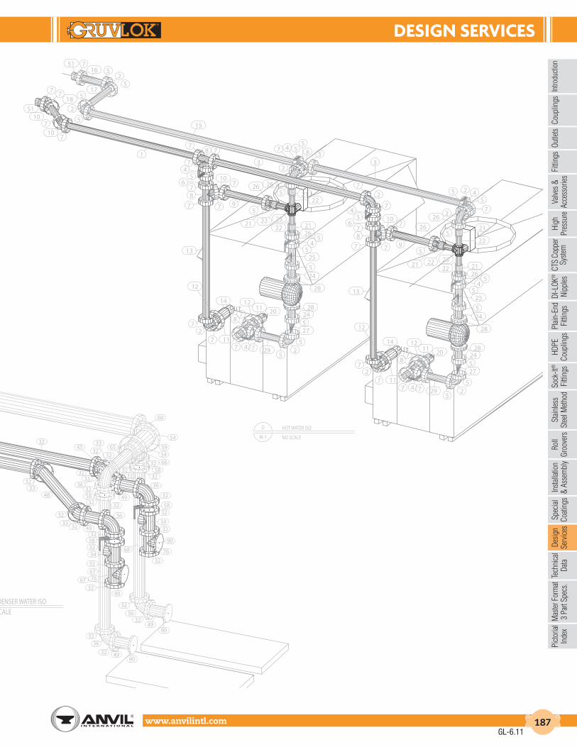
dESIGn SErVIcES
Intro
duct
ion
Coup
lings
Outle
tsFi
tting
sVa
lves
&
Acce
ssor
ies
High
Pres
sure
DI-L
OK®
Nipp
les
Plai
n-En
dFi
tting
sHD
PECo
uplin
gsSo
ck-It
®
Fitti
ngs
Stai
nles
sSt
eel M
etho
dRo
ll Gr
oove
rsIn
stal
latio
n&
Ass
embl
ySp
ecia
lCo
atin
gsDe
sign
Serv
ices
Tech
nica
lDa
taM
aste
r For
mat
3 Pa
rt Sp
ecs.
Pict
oria
lIn
dex
CTS
Copp
er
Syst
em
www.anvilintl.com 187
665459
54
60
3258
32
65
3233
32
48
32
3332 49
3332
3245
32
363258
32
33
32
49
32
36
32
5832
34
32
36
67
68
32583234
32
766732
90
32
76
90
32
3236
32 4990
3236
3249
90
71
46
47
5459 54 66
3279 32
36
42
43
3332 3232
33 32
32
36 32
32
3632
32
44
32
44
81
80
80
81
80
82
80
80
8280
84
83 84
8385
80
8280
5880
77
78
8058
8082
80
85
CM-1
CONDENSER WATER ISONO SCALE
D
M-1
HOT WATER ISO
NO SCALE
IN
IN
87
1211 20
7 4 7 295
25
27524
28
28
245
255
45
262122
23
22
2221
59
215
210
7
7
14
11
12
72
7
13
7
87
65
4
8
281124
2
527
5
20
529747
7
24
28
522
2322
222126
54
525
5
12
72
7 11
7
710
95
21
45
678
7
13
12
14
45
7
257
2
7
855
547
2
21
26
26
33
78 7
7
15
1
51 716 5
25
175
2
5
107
7
187
10
7
51
26
26
GL-6.11
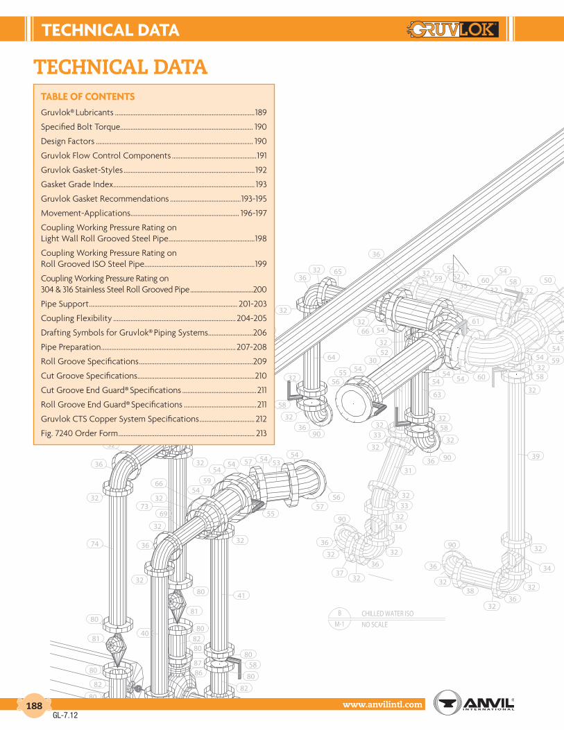
tEcHnIcAL dAtA
www.anvilintl.com188
B
M-1
CHILLED WATER ISO
NO SCALE
36
36
32
32 65
64
3332
32
9036
32
58
32
3266 54
5932
3532
5832
54
6054
32
3052
545556
63
9036
32
5832
32
5832
62
5454
61
54 60
54 59
5459
54
39
90
36
32
3732
36
32
3432
3332
31
90
36
3238
3236
32
34
32
72
59
54
5466
32
69
32
32
36
3257
56
5453545754
55
54
5954
66
32
69
32
36
32
32
80
73
74
41
40
80
81
80
82
80
87
86
8687
8082
80
81
89
8980
80
8280 58
82
80
5880
80
50
technical data
GL-7.12
tABLE oF contEntSGruvlok® Lubricants .................................................................................189
Specified Bolt Torque............................................................................. 190
Design Factors ........................................................................................... 190
Gruvlok Flow Control Components .................................................191
Gruvlok Gasket-Styles ............................................................................192
Gasket Grade Index .................................................................................. 193
Gruvlok Gasket Recommendations .........................................193-195
Movement-Applications ............................................................... 196-197
Coupling Working Pressure Rating onLight Wall Roll Grooved Steel Pipe ..................................................198
Coupling Working Pressure Rating onRoll Grooved ISO Steel Pipe................................................................199
Coupling Working Pressure Rating on304 & 316 Stainless Steel Roll Grooved Pipe ..........................................200
Pipe Support ...................................................................................... 201-203
Coupling Flexibility ....................................................................... 204-205
Drafting Symbols for Gruvlok® Piping Systems ..........................206
Pipe Preparation ..............................................................................207-208
Roll Groove Specifications ..................................................................209
Cut Groove Specifications ....................................................................210
Cut Groove End Guard® Specifications ...........................................211
Roll Groove End Guard® Specifications ..........................................211
Gruvlok CTS Copper System Specifications ................................ 212
Fig. 7240 Order Form ............................................................................... 213

tEcHnIcAL dAtA
Intro
duct
ion
Coup
lings
Outle
tsFi
tting
sVa
lves
&
Acce
ssor
ies
High
Pres
sure
DI-L
OK®
Nipp
les
Plai
n-En
dFi
tting
sHD
PECo
uplin
gsSo
ck-It
®
Fitti
ngs
Stai
nles
sSt
eel M
etho
dRo
ll Gr
oove
rsIn
stal
latio
n&
Ass
embl
ySp
ecia
lCo
atin
gsDe
sign
Serv
ices
Tech
nica
lDa
taM
aste
r For
mat
3 Pa
rt Sp
ecs.
Pict
oria
lIn
dex
CTS
Copp
er
Syst
em
www.anvilintl.com 189
B
M-1
CHILLED WATER ISO
NO SCALE
36
36
32
32 65
64
3332
32
9036
32
58
32
3266 54
5932
3532
5832
54
6054
32
3052
545556
63
9036
32
5832
32
5832
62
5454
61
54 60
54 59
5459
54
39
90
36
32
3732
36
32
3432
3332
31
90
36
3238
3236
32
34
32
72
59
54
5466
32
69
32
32
36
3257
56
5453545754
55
54
5954
66
32
69
32
36
32
32
80
73
74
41
40
80
81
80
82
80
87
86
8687
8082
80
81
89
8980
80
8280 58
82
80
5880
80
50
Gruvlok® lubricantsGruVLoK® XtrEMEtM LuBrIcAntGruvlok® Xtreme™ Lubricant has been developed for use with Gruvlok couplings in services where improved lubrication is beneficial. This lubricant has an operating temperature range from -65°F to 400°F (-53.8°C to 204°C), well exceeding the temperature range of Gruvlok gaskets. This lubricant is waterproof, thereby eliminating water wash-out and it will not dry out in the absence of water. There are five primary applications where the Xtreme Lubricant will provide increased benefits: low temperature applications below 32°F (0°C), high temperature applications above 150°F (65.6°C), applications where increased pipe joint flexibility is needed, lubrication of gaskets in copper systems, and for the lubrication of gaskets on HDPE couplings. Since it is formulated from a non-hydro carbon base, it can be used with EPDM, Nitrile and Fluoroelastomer gasket materials. It is not to be used with Silicone gaskets.
• In low temperature applications the gasket will shrink, thereby lowering the sealing force on the gasket sealing lips. The temperature change will also force the gasket to slightly re-position itself. This will cause pipe end sealing surfaces, with small cuts or damage, to become more susceptible to leakage. Gruvlok Xtreme Lubricant will maintain it’s lubricating properties at lower temperatures allowing a properly lubricated pipe end and gasket (assembly) to reposition itself during temperature cycles.
• For high temperature service and copper systems, it is required that the gasket be lubricated not only on the outside, as with the normal installation of a Gruvlok gasket, but also on the inside. Lubrication on the inside of the gasket is easily accom-plished by turning the gasket inside out and applying the lubricant. Gruvlok Xtreme Lubricant will maintain it’s lubricat-ing properties at higher temperatures, allowing a properly lubricated pipe end and gasket assembly to re-position itself during temperature cycles. Lubrication of the pipe end and gasket will help the gasket to adjust into the proper sealing position during temperature cycles. The lubricant on the interior of the gasket will act to improve the chemical resistance of the gasket material by providing a thin lubricant barrier between the piping system fluid and the gasket surface. This is particu-larly important at higher temperatures where oxidizing agents in the piping system become more aggressive. However, gasket chemical compatibility must still be considered.
• The Gruvlok Xtreme Lubricant has been formulated from low viscosity, non-petroleum based oils to ease spreading of the lubricant. In applications where pipe movement is expected, proper lubrication of the gasket’s exterior assists the gasket into the proper sealing position as pipe system movement occurs. This lubricating film enhances our flexible coupling gasket’s ability to compensate for axial, transverse and rotational pipe movements.
• Gruvlok Xtreme Lubricant is the only Gruvlok lubricant that is to be used with Gruvlok couplings and gaskets in HDPE and copper piping systems. It’s low temperature capability and lubricity ensure a highly reliable connection.
Gruvlok® XtremeTM Lubricant is a Teflon® fortified white, tasteless and odorless grease made from Silicone Oil and other ingredi-ents that are safe to ingest. It is sanctioned by the FDA under C.F.R. 21.172.878 & 21.177.1550 (Incidental Food Contact). It is NSF approved for use with potable water.
cAutIon: Silicone based lubricants are not allowed in some facilities. ®Teflon is a registered trademark of Dupont.
GruVLoK® QuIcK drY LuBrIcAntGruvlok® Quick Dry Lubricant is a fast drying lubricant that has been developed for applications where the piping system is exposed. The service temperature range for this lubricant is from 0° F to 150° F (-17.8°C to 65.6°C) and may be used with all Gruvlok gasket material grades. The lubricant is made from a water emulsion that is non-toxic, it will not impart taste or odor, and does not support bacterial growth. Gruvlok Quick Dry Lubricant is non-corrosive, non-flammable, and is NSF approved for use with potable water.
This lubricant is easy to apply by brush or hand, and it quickly dries to a thin film when in contact with air. It is water-soluble. The quick drying quality of the lubricant eliminates lubricant drips caused by over lubrication. If necessary, reapply lubricant prior to assembly. Do not thin or mix with solvents.
GruVLoK® LuBrIcAntGruvlok® Lubricant is the standard lubricant that has been provided for use with Gruvlok products for years. Gruvlok Lubricant is water soluble, non-toxic, non-corrosive, non-flammable, and will not impart taste or odor. It is NSF approved for use with potable water. This lubricant is acceptable for most applications, however, the Gruvlok Xtreme Lubricant and Gruvlok Quick Dry Lubricant are now available to improve the performance of the couplings and flanges in certain applications.cAutIon: HDPE pipe requires the use of Gruvlok Xtreme Lubricant and should not be used with Gruvlok Lubricant.
GL-7.12

tEcHnIcAL dAtA
www.anvilintl.com190
LInEAr MoVEMEntSizes Roll Groove Pipe Cut Groove Pipe
1" through 31⁄2" 1⁄32" 1⁄16"
4" though 24" 3⁄32" 3⁄16"
FLEXIBLE couPLInGAnGuLAr MoVEMEnt
Designed-in clearances allow limited deflection of the pipe joint within the coupling, without introducing eccentric loads into the coupling joint.
The maximum available angular movement of Gruvlok flexible couplings on roll groove joints is shown in the performance data for each coupling. The amount of angular flexibility varies for each coupling size and type. The values account for pipe, groove, and coupling tolerances.
specified bolt torQueSpecified bolt torque is for the oval neck track bolts used on Gruvlok couplings and flanges. The nuts must be tightened alternately and evenly until fully tightened. CAUTION: Use of an Impact wrench is not recommended because the torque output can vary significantly due to many variables including air pressure supply, battery strength and operational variations.
cAutIon: Proper torquing of coupling bolts is required to obtain specified performance. over torquing the bolts may result in damage to the bolt and/or casting which could result in pipe joint separation. Under torquing the bolts may result in lower pressure retention capabilities, lower bend load capabilities, joint leakage and pipe joint separation. Pipe joint separation may result in significant property damage and serious injury.
notE: Use specified bolt torque unless otherwise indicated on product installation pages.
desiGn factorsEach flexible design Gruvlok coupling can provide for pipe system movement up to the design maximum for the specific size and type of coupling being utilized. Movement is possible in the Gruvlok coupling due
to two factors: (1) designed-in clearance between the key of the coupling and the groove diameter and groove width, and (2) the gap between pipe ends joined by the coupling.
MoVEMEnt:
FLEXIBLE couPLInGLInEAr MoVEMEnt
Linear movement is accommodated within the coupling by allowing the pipe ends to move together or apart in response to pressure thrusts and temperature changes. The available linear movement provided by Standard Gruvlok couplings is shown below:
linear movement: anGular movement:
rIGId couPLInGS
Gruvlok rigid couplings Fig. 7400, Fig. 7401 and Fig. 7004 HPR are designed to provide a joint with the attributes of a welded or flanged connection. Therefore, these joints would remain in strict alignment and would resist deflection and linear movement during service.
FLEXIBLE couPLInGS
Figs. 7000, 7001, 7003, 7010 are the flexible couplings provided in the Gruvlok product line. The following information on movement applies to these flexible couplings.
AnSI SPEcIFIEd BoLt torQuE
Bolt Size
Wrench Size
Specified Bolt Torque *
In. In. Ft.-Lbs.
3⁄8 11⁄16 30-451⁄2 7⁄8 80-1005⁄8 11⁄16 100-1303⁄4 11⁄4 130-1807⁄8 17⁄16 180-220
1 15⁄8 200-250
11⁄8 113⁄16 225-275
11⁄4 2 250-300
MEtrIc SPEcIFIEd BoLt torQuE
Bolt Size
Wrench Size
Specified Bolt Torque *
mm mm N-m
M10 16 40-60
M12 22 110-150
M16 24 135-175
M20 30 175-245
M22 34 245-300
M24 36 270-340
* Non-lubricated bolt torques
* Non-lubricated bolt torques
Represents Linear Movement Capabilities
θ
θ/2
GL-7.12

tEcHnIcAL dAtA
Intro
duct
ion
Coup
lings
Outle
tsFi
tting
sVa
lves
&
Acce
ssor
ies
High
Pres
sure
DI-L
OK®
Nipp
les
Plai
n-En
dFi
tting
sHD
PECo
uplin
gsSo
ck-It
®
Fitti
ngs
Stai
nles
sSt
eel M
etho
dRo
ll Gr
oove
rsIn
stal
latio
n&
Ass
embl
ySp
ecia
lCo
atin
gsDe
sign
Serv
ices
Tech
nica
lDa
taM
aste
r For
mat
3 Pa
rt Sp
ecs.
Pict
oria
lIn
dex
CTS
Copp
er
Syst
em
www.anvilintl.com 191
HorIZontAL SPLIt cASE PuMP
Gruvlok® flow controlComponents
Anvil has put together a complete array of Gruvlok components necessary to provide pump protection for HVAC and industrial piping needs. With the combination of the Fig. 7401 Rigidlok and Fig. 7001 Standard coupling, flex connectors can be eliminated thus reducing cost. The Series 7700 Gruvlok® Butterfly valve has superior flow characteristics. The Gruvlok® Series 7800 Check Valve is full waterway valve and can be stacked directly to the Series 7700 Butterfly Valve. The Fig. 7250 Suction Diffuser and Fig. 7260 Tee Strainer complete the Gruvlok® pump protection package.
VErtIcAL SPLIt cASE PuMP
End SuctIon PuMP
GL-6.11

tEcHnIcAL dAtA
www.anvilintl.com192
Gruvlok Gasket-styles
Gruvlok offers a variety of pressure responsive gasket styles. Each serves a specific function while utilizing the same basic sealing concept. Proper installation of the gasket compresses the inclined gasket lips on the pipe O.D., forming a leak tight seal. This sealing action is reinforced when the gasket is encompassed and compressed by the coupling housings. The application of internal line pressure energizes the elastometric gasket and further enhances the gasket sealing action.
The “C” Style cross section configuration is the most widely used gasket. It is the gasket style provided as standard in many Gruvlok Couplings (Fig. 7000, 7001, 7003, 7004HPR, 7307, 7400 and 7401). Grade “E” and “T” are standard grades while other grades are available for special applications.
“c” style rouGhneck®
This “C” style gasket is similar in appearance and design to the Standard gasket but is only used with Fig. 7005 Roughneck Couplings and Fig. 7305 HDPE Couplings. The Roughneck gasket is wider, which allows for minor pipe end separation as line pressure sets the grippers into the plain end pipe.
end Guard™ flush Gap™
The projecting rib fits between the ends of lined pipe to prevent damage to unprotected pipe ends during coupling joint assembly.
The E.G. gasket is provided as standard with the Fig. 7004 E.G. Coupling.
Grade “E” and “T” gaskets are available.
Designed to prohibit contaminates from building up in the gasket cavity. The centering rib fits flush over the gap between the two pipe ends thus closing off the gasket cavity. It can be used with Fig. 7000, 7001, 7400 and 7401 Couplings for many applications. Recommended for use in dry fire protection systems.
reducinG couplinG flanGe
The centering rib allows for pipe positioning and serves to keep the smaller pipe from telescoping during installation. Used only with the Fig. 7010 Reducing Coupling.
A specially designed gasket for the Fig. 7012, 7013 and 7312 Flange provides for a reliable seal on both the pipe and the mating flange.
sock-it® clamp-t™
Used in Sock-It fittings only, this pressure energized gasket provides a leak-tight seal on plain end seal pipe. Available in Grade “E” material only.
These gaskets conform to the curved exterior of the pipe to provide a pressure responsive seal. This unique design is only used with Fig. 7045, 7046 Clamp-T and Fig. 7047, 7048, and 7049 Clamp-T Crosses.
GL-6.11

tEcHnIcAL dAtA
Intro
duct
ion
Coup
lings
Outle
tsFi
tting
sVa
lves
&
Acce
ssor
ies
High
Pres
sure
DI-L
OK®
Nipp
les
Plai
n-En
dFi
tting
sHD
PECo
uplin
gsSo
ck-It
®
Fitti
ngs
Stai
nles
sSt
eel M
etho
dRo
ll Gr
oove
rsIn
stal
latio
n&
Ass
embl
ySp
ecia
lCo
atin
gsDe
sign
Serv
ices
Tech
nica
lDa
taM
aste
r For
mat
3 Pa
rt Sp
ecs.
Pict
oria
lIn
dex
CTS
Copp
er
Syst
em
www.anvilintl.com 193
GRUVLOK
WAtEr & AIrService Gasket Grade
Air, (no oil vapors) Temp. -40°F to 230°F (-40°C to 110°C) E/EPAir, (no oil vapors) Temp. -40°F to 350°F (-40°C to 177°C) LAir, Oil vapor Temp. -20°F to 150°F (-29°C to 66°C) TAir, Oil vapor Temp. 20°F to 300°F (-7°C to 149°C) OWater, Temp to 150°F (66°C) E/EP/TWater, Temp to 230°F (110°C) EWater, Acid Mine E/TWater, Chlorine (E/EP/O)Water, Deionized E/EP/TWater, Seawater E/EP/TWater, Waste E/EP/TWater, Lime E/EP/T
StAndArd GASKEtS
Grade Temp. Range Compound Color
Code General Service Applications
E-40°F to +230°F (-40°C to 110°C)
EPDM Green
Water, dilute acids, alkalies, salts, and many chemical services not involving hydrocarbons, oils, or gases. Excellent oxidation resistance.
NOT FOR USE WITH HYDROCARBONS
EP-40°F to +250°F (-40°C to 121°C)
EPDM Green and Red
Water, dilute acids, alkalies, salts, and many chemical services not involving hydrocarbons, oils, or gases. Excellent oxidation resistance.
NOT FOR USE WITH HYDROCARBONS
T-20°F to +180°F (-29°C to
82°C)
Nitrile (Buna-N) Orange
Petroleum products, vegetable oils, mineral oils, and air contaminated with petroleum oils.
NOT FOR USE IN HOT WATER SERVICES
Gasket Grade index & Gasketrecommendation
Gasket Grade index
Gasket recommendation listinG
vacuum service
Where more than one gasket grade is shown the preferred gasket grade is listed first. Where the gasket grade is shown in parentheses, Contact an Anvil Representative for an engineering evaluation and recommendation. Specify gasket grade when ordering. Use Gruvlok lubricant on gasket. Check gasket color code to be certain it is recommended for the service intended.
Unless otherwise noted, all gasket listings are based upon 100°F (38°C) maximum temperature service conditions.For services not listed, contact an Anvil Representative for recommendation.*Contact an Anvil Representative for service evaluation.
LARGER SIzES: Contact an AnvilRepresentative for more information.
SPEcIAL GASKEtS
Grade Temp. Range Compound Color
Code General Service Applications
O+20°F to +300°F (-20°C to 149°C)
Fluoro Elastomer Blue
High temperature resistance to oxidizing acids, petroleum oils, hydraulic fluids, halogenated, hydrocarbons and lubricants
L-40°F to +350°F (-40°C to 177°C)
Silicone Red Gasket
Dry, hot air and some high temperature chemical services.
E Type
A
-40°F to +150°F (-40°C to
66°C)
Pre- Lubricated Violet
Wet & Dry (oil free air) Pipe in Fire Protection Systems. For dry pipe systems, Gruvlok Xtreme™ Temperature Lubricant is required.
PEtroLEuM ProductSService Gasket Grade
Crude Oil - Sour TDiesel Oil TFuel Oil TGasoline, Leaded TGasoline, Unleaded* (O)Hydraulic Oil TJP-3, JP-4 and JP-5 T/OJP-6, 100°F (38°C) Maximum Temp. OKerosene TLube Oil, to 150°F (66°C) TMotor Oil TTar and Tar Oil TTransmission Fluid —Type A OTurbo Oil #15 Diester Lubricant O
VAcuuM SErVIcESize Vacuum Level Gasket Recommendation
1" - 12" (25 - 300mm) 0" - 10" Hg Standard or Flush Gap
11⁄2" - 12" (40 - 200mm) 10" - 29.9" Hg Flush Gap
The lists are provided as an aid in selecting the optimum gasket grade for a specific application to assure the maximum service life.
The recommendations have been developed from current information supplied by manufacturers of the elastomers, technical publications, and industry applications. The information supplied should be considered as a basis for evaluation but not as a guarantee.
Selection of the optimum gasket grade for a specific service requires the consideration of many factors; primarily temperature, fluid concentration, and continuity of service. Unless otherwise noted, all gasket recommendations are based on 100°F (38°C) maximum temperature service condition. Where more than one gasket grade is shown, the preferred grade is listed first.
Combinations of fluids should be referred to an Anvil Representative for an engineering evaluation and recommendation. In unusual or severe services, gasket materials should be subjected to simulated service conditions to determine the most suitable gasket grade.
Gasket recommendations apply only to Gruvlok gaskets. Contact an Anvil Representative for recommendations for services not listed. These listings do not apply to Gruvlok Butterfly Valves.
All Gruvlok products marked with UL/ULC Listed, FM approved VdS and/or LPC symbols are Listed/Approved with EPDM material. For other Listed/Approved materials, please contact an Anvil Representative for more information.
GL-6.11

tEcHnIcAL dAtA
www.anvilintl.com194
Gruvlok Gasket-recommendations
Where more than one gasket grade is shown the preferred gasket grade is listed first.Where the gasket grade is shown in parentheses, Contact an Anvil Representative for anengineering evaluation and recommendation.Check gasket grade when ordering. Use Gruvlok lubricant on gasket.
Unless otherwise noted, all gasket listings are based upon 100°F (38°C) maximum temperatureservice conditions. For services not listed, Contact an Anvil Representative for recommendation.Check gasket color code to be certain it is recommended for the service intended.
cHEMIcAL SErVIcES
Chemical Composition Gasket Grade
Acetic Acid 50% E/EPAcetic Acid Glacial L/E/EPAcetone E/EPAcethlene E/EP/T
Alkalis T/E/EPAlums E/EP/T/OAluminum Chloride E/EP/TAluminum Fluoride E/EP/T/O
Aluminum Hydroxide E/EP/OAluminum Nitrate E/EP/TAluminum Salts E/EPAmmonia Gas, Cold E/EP
Ammonia Liquid E/EPAmmonium Chloride T/E/EPAmmonium Fluoride E/EPAmmonium Hydroxide E/EP
Ammonium Nitrate T/E/EPAmyl Acetate E/EPAmyl Alcohol E/EPAniline E/EP
Animal Fats TArgon-Gas LArsenic Acid, to 75% T/E/EP/OBarium Carbonate E/EP/T
Barium Chloride E/EP/TBarium Hydroxide E/EP/TBarium Nitrate E/EP/OBarium Sulphide E/EP/T
Beet Sugar Liquors TBenzene OBenzene Sulfonic (Aromatic Acid) (E/EP)Benzoic Acid O
Benzyl Alcohol E/EPBenzyl Chloride E/EPBlack Sulphate Liquor TBleach, 5% Active CI2 E/EP/O
Borax E/EP/OBoric Acid E/EP/TBromine OButyl Alcohol E/EP/T
Butyl Stearate E/EPButylene T/OCalcium Bisulfate T/OCalcium Bisulphide T/O
Calcium Bisulphite T/OCalcium Carbonate E/EP/TCalcium Chloride E/EP/TCalcium Hydroxide (Lime) E/EP/T
cHEMIcAL SErVIcES
Chemical Composition Gasket Grade
Calcium Sulfate E/EP/TCalcium Sulfide E/EP/TCaliche Liquors E/EP/TCane Sugar Liquors T
Carbitol E/EP/TCarbon Dioxide, Dry E/EP/TCarbon Dioxide, Wet E/EP/TCarbon Monoxide E/EP
Carbon Tetrachloride OCastor Oil TCaustic Potash E/EPCaustic Soda E/EP
Cellosolve E/EPChlorine Dry (O)Chlorinate Solvents (O)Chlorobenzene O
Chlorobenzene Chloride OChlorobromomethane OChloroform OChrome Alum E/T
Chrome Plating Solutions OChromic Acid, to 50% OCitric Acid E/EP/TCoconut Oil T
Cod Liver Oil TCoke Oven Gas T/OCopper Carbonate E/EP/TCopper Chloride E/EP/T
Copper Cyanide E/EP/TCopper Sulphate E/EP/TCorn Oil TCotton Seed Oil T
Cresole, Cresylic Acid T/OCreosote, Coal Tar (T/O)Creosote, Wood T/OCupric Chloride E/EP/T
Cupric Fluoride E/EP/TCupric Sulphate E/EP/TCychohexanol ODiacetone Alcohol E/EP
Dichlorobenzene ODichloroethylene ODioctyl Phthalate (E/EP)Epson-Salt E/EP/T
Ethane E/EPEthanolamine E/EPEthyl Acetate (E/EP)Ethyl Alcohol E/EP/T
cHEMIcAL SErVIcES
Chemical Composition Gasket Grade
Ethyl-Chloride E/EP/TEthyl Ether (T)Ethylene Chloride E/EPEthylene Chlorohydrin E/EP
Ethylene Diamine E/EP/TEthylene Dichloride (Dichloroethane) OEthylene Glycol E/EP/TEthylene Oxide (E/EP)
Ferric Chloride, to 35% E/EP/TFerric Nitrate E/EP/TFerric Sulphate E/EP/TFerrous Chloride E/EP/T
Fish Oils TFluroboric Acid E/EPFluorosilicic Acid E/EPFly-Ash E/EP
Formaldehyde E/EP/TFormamide E/EP/TFormic Acid E/EP/OFreon 11, 130°F (54°C) Max. T
Freon 12, 113, 114, 115, 130°F (54°C) Max. TFructose TFurfuryl Alcohol (E/EP)Glucose E/EP/T
Glue TGlycerin E/EP/TGlycerol E/EP/TGlycol E/EP/T
Heptane THexaldehyde E/EPHexane THexylene Glycol T
Hydrochloric Acid, to 36%, 75°F (24°C)-Max. E/EPHydrochloric Acid, to 36%, 158°F (70°C)-Max. (O)Hydrofluoric Acid, to 75%, 158°F (70°C)-Max. (O)Hydrofluosilicic Acid T/E/EP
Hydrogen Peroxide, to 50% E/EP/T/OHydrogen Peroxide, to 90% (L/O)Hydroquinone T/OIodine,-Wet E/EP
Isoamyl Alcohol E/EPIsooctane TIsobutyl Alcohol E/EPIsopropyl Alcohol E/EP
Lacquer (O)Lacquer Solvent (O)Lactic Acid TLard Oil T
GL-6.11

tEcHnIcAL dAtA
Intro
duct
ion
Coup
lings
Outle
tsFi
tting
sVa
lves
&
Acce
ssor
ies
High
Pres
sure
DI-L
OK®
Nipp
les
Plai
n-En
dFi
tting
sHD
PECo
uplin
gsSo
ck-It
®
Fitti
ngs
Stai
nles
sSt
eel M
etho
dRo
ll Gr
oove
rsIn
stal
latio
n&
Ass
embl
ySp
ecia
lCo
atin
gsDe
sign
Serv
ices
Tech
nica
lDa
taM
aste
r For
mat
3 Pa
rt Sp
ecs.
Pict
oria
lIn
dex
CTS
Copp
er
Syst
em
www.anvilintl.com 195
Gruvlok Gasket-recommendations (cont.)
cHEMIcAL SErVIcES
Chemical Composition Gasket Grade
Latex (1% Styrene &-Butadiene) OLead Acetate E/EP/TLinseed Oil TLithium Bromide T/O
Magnesium Chloride E/EP/TMagnesium Hydroxide E/EP/TMagnesium Nitrate E/EPMagnesium Sulphate E/EP/T
Malonyl Nitrile E/EP/TMercuric Chloride E/EP/TMercuric Cyanide E/EP/TMercury E/EP/T
Methyl Acetate (E/EP)Methyl Alcohol, Methanol E/EP/TMethyl Cellosolve (Ether) E/EPMethyl Chloride (O)
Methyl Ethyl Ketone (E/EP)Methyl Formate E/EPMethyl Isobutyl Carbinol E/EP/TMethyl Isobutyl Ketone (E/EP)
Mineral Oils TNaphtha, 160°F (71°C)-Max. ONaphthalene 176°F ONickel Chloride E/EP/T
Nickel Nitrate E/EPNickel Plating Solution 125°F (52°C)-Max. E/EPNitric Acid, to 10%, 75°F-(24°C)-Max. E/EPNitric Acid, 10-50%, 75°F-(24°C)-Max. O
Nitric Acid, 50-86%, 75°F (24°C)-Max. (O)Nitric Acid, Red Fuming (O)Nitro Benzene (O)Nitrous Oxide E/EP
Octyl Alcohol TOlive Oil TOxalic Acid E/EPOzone E/EP
Phenol (Carbolic acid) 300°F (149°C)-Max. OPhenylhydrazine (O)Phosphate Ester E/EPPhosphoric Acid, to 75% & 70°F (21°C)-Max. E/EP/T
cHEMIcAL SErVIcES
Chemical Composition Gasket Grade
Phosphoric Acid, to 85% & 150°F (66°C) Max. OPhotographic Solutions TPotassium Bromide E/EP/TPotassium Carbonate E/EP/T
Potassium Chloride E/EP/TPlating Solutions (gold, brass cadmium, E/EP
copper, lead, silver, tin, zinc)
Potassium Chromate T
Potassium Cyanide E/EP/TPotassium Ferricyanide E/EP/TPotassium Ferrocyanide E/EP/TPotassium Hydroxide T
Potassium Iodide E/EP/TPotassium Nitrate E/EP/TPotassium Permanganate, saturated, to 25% E/EPPotassium Sulphate E/EP/T
Propanol E/EPPropyl Alcohol E/EP/TPropylene Glycol E/EP/TPydraul 312C O
Pyroguard “C” &-“D” TPyroguard 55 E/EPPyrrole E/EPSalicylic Acid E/EP/T
Silver Cyanide E/EPSilver Nitrate E/EPSkydrol, 200°F (93°C)-Max. LSkydrol 500 Phosphate Ester (L/E/EP)
Soda Ash,-Sodium Carbonate E/EP/TSodium Bicarbonate E/EP/TSodium Bisulphate E/EP/TSodium Bisulphite (black liquor) E/EP/T
Sodium Bromide E/EP/TSodium Chlorate E/EP/TSodium Chloride E/EP/TSodium Cyanide E/EP/T
Sodium Hydroxide, to 50% E/EPSodium Hypochlorite, to 20% E/EPSodium Metaphosphate E/EP/TSodium Nitrate E/EP/T
cHEMIcAL SErVIcES
Chemical Composition Gasket Grade
Sodium Peroxide E/EPSodium Phosphate E/EP/TSodium Silicate E/EP/TSodium Sulphide E/EP/T
Sodium Sulphite Solution, to 20% E/EP/TSodium Thiosulphate, “Hypo” E/EP/TSoybean Oil TStannous Chloride, to 15% E/EP/T/O
Starch E/EP/TStearic Acid TStyrene OSucrose Solutions T
Sulphur E/EPSulphuric Acid, to 25%, 150°F (66°C)-Max. E/EPSulphuric Acid, 25-50%, 200°F (93°C) Max. OSulphuric Acid, 50-95%, 150°F-(66°C)-Max. O
Sulphuric Acid, Fuming (O)Sulphuric Acid, Oleum (O)Sulphurous Acid (O)Tetrachloroethylene O
Toluene OTributyl Phosphate (E/EP)Trichloroethylene, 200°F-(93°C)-Max OTriethanolamine E/EP/T
Trisodium Phosphate (E/EP/T)Turpentine 158°F-(70°C)-Max. T/OUrea E/EP/TVegetable Oils T
Vinegar TVinyl Acetate (E/EP)White Liquor E/EPXylene (Xylol)-158°F (70°C)-Max. OZinc Sulphate E/EP/T
GL-6.11
Where more than one gasket grade is shown the preferred gasket grade is listed first.Where the gasket grade is shown in parentheses, Contact an Anvil Representative for anengineering evaluation and recommendation.Check gasket grade when ordering. Use Gruvlok lubricant on gasket.
Unless otherwise noted, all gasket listings are based upon 100°F (38°C) maximum temperatureservice conditions. For services not listed, Contact an Anvil Representative for recommendation.Check gasket color code to be certain it is recommended for the service intended.

tEcHnIcAL dAtA
www.anvilintl.com196
movement-applications
thermal movement misaliGnment & deflectionA sufficient amount of coupling joints must be provided to accommodate the calculated movement (expansion or contraction) in a pipe run or segment thereof .
The angular movement capability of the Gruvlok coupling permits the assembly of pipe joints where the piping is not properly aligned. At least two couplings are required to provide for lateral pipe misalignment. Deflection (longitudinal misalignment) may be accommodated within a single coupling as long as the angle of deflection does not exceed the value shown in the coupling performance data for the particular size and coupling type.
A pipe joint that utilizes the angular deflection capability of the Gruvlok coupling will react to pressure and thermal forces dependent upon the manner in which it is restrained. An unrestrained joint will react to these forces by straightening, thus reducing, if not eliminating, the deflection at the joint. If joint deflection has been designed into the pipe layout and must be maintained, then sufficient anchors must be provided to resist the lateral forces and hold the joint in the deflected condition.
EXAMPLE:A 200 foot long straight run of 4" steel cut grooved pipe between anchor points . Minimum Temperature: 40° F (4 .4° C) . (at time of installation) . Maximum Oper . Temperature: 160° F (71 .1° C) .
Thermal expansion tables show this system will expand a total of 1 .80" due to the temperature change .
dESIGn QuEStIon:How many couplings are required to account for the thermal growth?
AVAILABLE LInEAr MoVEMEnt PEr FLEXIBLE couPLInG:Using the table on page 190, we see that there is 0 .188" linear movement per coupling (4" Flexible Coupling)
couPLInGS rEQuIrEdAs indicated above, the total movement is 1 .80". Thus, the number of couplings is determined as follows:
No . of Couplings = Tot . Movement / Avail . Movement per Coupling
FOR OUR EXAMPLE:No . of Couplings = (1 .80") / (0 .187") = 9 .6,Therefore 10 couplings are needed
PoSItIon oF couPLInGSIn order for the couplings to provide for the movement indicated by the above example, it would be necessary to install all couplings with the maximum gap between pipe ends. Conversely, if the thermal movement was contraction due to a reduction of system temperature, the coupling joints would have be installed with the pipe ends butted, thus accommodating the “shrink” of the pipe system.
In either case the pipe run in question would have to be anchored at the proper locations to direct pipe system expansion or contraction into the coupling joints.
As can be seen from the above example, the pipe end gap within the coupling joint must be considered when designing a grooved end pipe system to accommodate thermal movement. The couplings do not automatically provide for expansion and contraction of piping.
The amount of deflection from pipe run centerline can be calculatedutilizing the following equations:
WHErE: M = Misalignment (inches)
G = Maximum Allowable Pipe End Movement (Inches) as shown under “Performance Data”
0 = Maximum Deflection (Degrees) from centerline as shown under “Performance Data”
D = Pipe Outside Diameter (Inches)
L = Pipe Length (Inches)
200 FEET
GM
LG
M
L
GL-7.12

tEcHnIcAL dAtA
Intro
duct
ion
Coup
lings
Outle
tsFi
tting
sVa
lves
&
Acce
ssor
ies
High
Pres
sure
DI-L
OK®
Nipp
les
Plai
n-En
dFi
tting
sHD
PECo
uplin
gsSo
ck-It
®
Fitti
ngs
Stai
nles
sSt
eel M
etho
dRo
ll Gr
oove
rsIn
stal
latio
n&
Ass
embl
ySp
ecia
lCo
atin
gsDe
sign
Serv
ices
Tech
nica
lDa
taM
aste
r For
mat
3 Pa
rt Sp
ecs.
Pict
oria
lIn
dex
CTS
Copp
er
Syst
em
www.anvilintl.com 197
movement-applications (cont.)
curve layout: combined linear & anGular movement:Utilizing the angular deflection at each coupling joint curves may be laid out using straight pipe lengths and Gruvlok Couplings.
The clearance in the grooved coupling joint, will allow a limited capability for combined linear and angular movement. A partially deflected joint will not provide full linear movement capability. A fully deflected coupling joint provides no linear movement capability. The Gruvlok coupling will not allow for both maximum linear and maximum angular movement simultaneously.
In systems where both are expected, additional joints may be required.
This example shows how to calculate the curve radius, required pipe lengths, and number of required couplings.
R = L/(2 x Sin(0/2))L = 2 x R x Sin(0/2)N = T/0
WHErE: N = Number of Couplings
R = Radius of Curve (feet)
L = Pipe Length (feet)
0 = Deflection from centerline (Degrees, Minutes) of each Coupling (See coupling performance data)
T = Total Angular Deflection of all Couplings.
drAInAGE, BurIEd SYStEMS, Etc.:The flexible design of the Gruvlok coupling makes it ideal for use in a wide variety of systems in which random changes of the pipe direction can be accommodated by the Gruvlok coupling’s angular deflection capability rather than requiring the use of special fittings.
Pitched drainage systems, buried pipe systems where pipe laying conditions are subject to settlement, and exposed pipe systems laid on rough ground are but a few of the many types of pipe installations that present conditions where the functional capability of the Gruvlok coupling are useful.
notE: Fully deflected Joint Will not Allow For Linear Expansion.
In the example above, two couplings were added to account for thermal expansion and the other couplings accommodate only the misalignment.
The additional stress from the combined movement is therefore relieved.
rotAtIonAL MoVEMEnt:Piping systems designed with Gruvlok Couplings can accommodate minor rotational movement from thermal expansion, settlement, vibration, or other similar movements. However, Gruvlok Couplings should never be used as a continuous swivel joint.
Utilizing the rotational capability of the Gruvlok Coupling, the pipe life of a slurry or similar coarse material piping system can be extended.
For pipe rotation, the system must be shut down and internal pressure relieved.
The pipe may then be rotated one-quarter turn, the couplings re-tightened, and service resumed. If performed on a regular basis, pipe rotation will evenly distribute wear over the entire inner surface of the pipe.
EXAMPLE:
R
R
R
L
T = N x θ
θ
Pitched for Drainage
Buried Pipe Systems
For Deflection
For Expansion
Before Pipe Rotation After Pipe Rotation
GL-7.12

tEcHnIcAL dAtA
www.anvilintl.com198
couplinG workinG pressure ratinGon Light Wall Roll Grooved Steel Pipe
Maximum line pressure, including surge, to which a joint should be subjected on pipe roll grooved to standard roll grooving specification with coupling properlyassembled. For coupling performance on standard wall steel pipe, refer to individual Gruvlok Coupling performance listing.* Rating based on larger pipe size.
GruVLoK couPLInG WorKInG PrESSurE rAtInG (PSI) on LIGHt WALL roLL GrooVEd StEEL PIPE
Nominal Size O.D. Nom. Wall
ThicknessPipe
ScheduleMaximum Working Pressure (PSI*)
Fig. 7000 Fig. 7001 Fig. 7003 Fig. 7004 Fig. 7010* Fig. 7012 Fig. 7013 Fig. 7400 Fig. 7401In./DN(mm) In./mm In. Number Lightweight Standard Hingelok HPR Reducing Flange Flange Rigidlite Rigidlok
1 25
1.315 33.4
0.065 5 300 500 – – – – – 175 –0.085 XL 300 300 – – – – – 300 –0.109 10 600 750 – – – – – 300 –
11⁄432
1.66042.2
0.065 5 300 500 – – – – – 175 –0.085 XL 300 300 – – – – – 300 –0.109 10 600 750 – – – – – 300 –
11⁄2 40
1.90048.3
0.065 5 300 500 200 – – – – 175 5000.090 XL 300 300 250 – – – – 300 3000.109 10 600 750 300 – – – – 300 750
250
2.37560.3
0.065 5 300 500 200 500 250 200 500 175 5000.090 XL 300 300 250 300 300 300 300 300 3000.109 10 600 750 300 800 350 300 720 300 750
21⁄265
2.87573.0
0.083 5 300 500 200 500 250 200 500 175 5000.130 XL 300 300 250 300 300 300 300 300 3000.120 10 600 750 300 800 350 300 720 300 750
380
3.50088.9
0.083 5 300 500 200 500 250 200 500 175 5000.130 XL 300 300 250 300 300 300 300 300 3000.120 10 600 750 300 800 350 300 720 300 750
31⁄2 4.000 0.083 5 300 500 – – – – – – –90 101.6 0.120 10 600 750 – – – – – – –4 4.500 0.083 5 300 500 200 400 200 200 500 175 500
100 114.3 0.120 10 600 750 300 600 300 300 720 300 7505 5.563 0.109 5 250 400 200 400 200 200 400 175 400
125 141.3 0.134 10 500 500 250 600 300 300 500 300 500
6150
6.625168.3
0.109 5 250 350 150 400 200 200 350 175 3500.134 10 400 500 200 500 300 300 500 300 5000.188 – 400 500 200 700 350 300 500 300 500
8200
8.625219.1
0.109 5 250 300 150 300 150 200 300 175 3000.148 10 350 400 200 400 250 300 400 175 4000.188 – 350 400 200 500 300 300 400 300 4000.250 20 350 500 250 600 300 300 500 300 500
10250
10.750273.1
0.134 5 – 250 – 300 – 200 250 – 2500.165 10 – 350 – 400 – 200 350 – 3500.188 – – 350 – 400 – 300 350 – 3500.250 20 – 400 – 500 – 300 400 – 400
12300
12.750323.9
0.156 5 – 200 – 200 – 200 200 – 2000.180 10 – 350 – 300 – 200 350 – 3500.188 – – 350 – 300 – 300 350 – 3500.250 20 – 400 – 400 – 300 400 – 400
14350
14.000355.6
0.156 5 – 125 – – – 125 – – 1250.250 10 – 250 – – – 250 – – 2500.312 20 – 275 – – – 250 – – 275
16 400
16.000406.4
0.165 5 – 125 – – – 100 – – 1000.250 10 – 175 – – – 175 – – 1750.312 20 – 275 – – – 250 – – 275
18 18.000 0.250 10 – 100 – – – 100 – – 100450 457.2 0.312 20 – 175 – – – 175 – – 17520 20.000 0.250 10 – 100 – – – 100 – – 100500 508.0 0.375 20 – 300 – – – 250 – – 25024 24.000 0.250 10 – 75 – – – 75 – – 75600 609.6 0.375 20 – 300 – – – 250 – – 250
GL-6.11

tEcHnIcAL dAtA
Intro
duct
ion
Coup
lings
Outle
tsFi
tting
sVa
lves
&
Acce
ssor
ies
High
Pres
sure
DI-L
OK®
Nipp
les
Plai
n-En
dFi
tting
sHD
PECo
uplin
gsSo
ck-It
®
Fitti
ngs
Stai
nles
sSt
eel M
etho
dRo
ll Gr
oove
rsIn
stal
latio
n&
Ass
embl
ySp
ecia
lCo
atin
gsDe
sign
Serv
ices
Tech
nica
lDa
taM
aste
r For
mat
3 Pa
rt Sp
ecs.
Pict
oria
lIn
dex
CTS
Copp
er
Syst
em
www.anvilintl.com 199
Maximum line pressure, including surge, to which a joint should be subjected on pipe roll grooved to standard roll grooving specification with coupling properly assembled. For coupling performance on standard wall steel pipe, refer to individual Gruvlok Coupling performance listing.* Rating based on larger pipe size.
couplinG workinG pressure ratinGon Roll Grooved ISO Size Steel Pipe
GruVLoK couPLInG WorKInG PrESSurE rAtInG (BAr) on roLL GrooVEd ISo SIZE StEEL PIPE
Nominal Size O.D. Nom. Wall
ThicknessMaximum Working Pressure (bar)
Fig. 7000 Fig. 7001 Fig. 7003 Fig. 7004 Fig. 7010* Fig. 7012 Fig. 7013 Fig. 7400 Fig. 7401In./DN(mm) In./mm mm Lightweight Standard Hingelok HPR Reducing Flange Flange Rigidlite Rigidlok
1 1.315 1.8 20.7 34.5 – – – – – 12.1 –25 33.4 2.9 41.4 51.7 – – – – – 20.7 –
3.2 41.4 69.0 – – – – – 20.7 –11⁄4 1.660 1.8 20.7 34.5 – – – – – 12.1 –32 42.2 2.9 41.4 51.7 – – – – – 20.7 –
3.6 41.4 69.0 – – – – – 20.7 –11⁄2 1.900 1.8 20.7 34.5 13.8 – – – – 12.1 34.540 48.3 2.9 41.4 51.7 17.2 – – – – 20.7 51.7
3.6 41.4 69.0 20.7 – – – – 20.7 51.72 2.375 1.8 20.7 34.5 13.8 34.5 17.2 13.8 34.5 12.1 34.550 60.3 2.9 41.4 51.7 17.2 55.2 24.1 20.7 51.7 20.7 51.7
3.6 41.4 69.0 20.7 82.3 24.1 20.7 69.0 20.7 51.721⁄2 2.875 2.0 20.7 34.5 13.8 34.5 17.2 13.8 34.5 12.1 34.565 73.0 3.2 41.4 51.7 17.2 55.2 24.1 20.7 51.7 20.7 51.7
5.0 41.4 69.0 20.7 82.3 24.1 20.7 69.0 20.7 51.73 O.D. 2.996 2.0 20.7 34.5 – – – 13.8 – 12.1 34.576.1 76.1 3.2 41.4 51.7 – – – 20.7 – 20.7 51.7
5.0 41.4 69.0 – – – 20.7 – 20.7 51.73 3.500 2.0 20.7 34.5 13.8 34.5 17.2 13.8 34.5 12.1 34.580 88.9 3.2 41.4 51.7 17.2 55.2 24.1 20.7 51.7 20.7 51.7
5.6 41.4 69.0 20.7 82.3 24.1 20.7 69.0 20.7 51.731⁄2 4.000 2.0 20.7 34.5 – – – – – – –90 101.6 3.2 41.4 51.7 – – – – – – –
5.6 41.4 69.0 – – – – – – –4 4.500 2.0 20.7 34.5 13.8 27.6 13.8 13.8 34.5 12.1 34.5
100 114.3 3.2 41.4 51.7 17.2 41.4 20.7 20.7 51.7 20.7 51.75.6 41.4 69.0 20.7 82.3 24.1 20.7 69.0 20.7 51.7
41⁄4 O.D. 4.250 2.0 20.7 – – – – – – – –108.0 108.0 3.2 41.4 – – – – – – – –
5.6 41.4 – – – – – – – –5 5.563 2.9 17.2 27.6 10.3 27.6 13.8 13.8 27.6 12.1 27.6
125 141.3 3.6 34.5 34.5 13.8 41.4 20.7 20.7 34.5 20.7 34.56.3 34.5 69.0 20.7 82.3 24.1 20.7 69.0 20.7 51.7
51⁄4 O.D. 5.236 2.9 17.2 – – – – – – – –133.0 133.0 3.6 34.5 – – – – – – – –
6.3 34.5 – – – – – – – –51⁄2 O.D. 5.500 2.9 17.2 – – – – 13.8 – 12.1 –139.7 139.7 3.6 34.5 – – – – 20.7 – 20.7 –
6.3 34.5 – – – – 20.7 – 20.7 –6 6.625 2.9 17.2 24.1 10.3 27.6 13.8 13.8 24.1 12.1 24.1
150 168.3 3.6 27.6 34.5 13.8 34.5 20.7 20.7 34.5 20.7 34.57.1 27.6 69.0 20.7 82.3 24.1 20.7 69 20.7 51.7
61⁄4 O.D. 6.259 2.9 17.2 – – – – – – – –159.0 159.0 3.6 27.6 – – – – – – – –
7.1 27.6 – – – – – – – –61⁄2 O.D. 6.500 2.9 17.2 24.1 – – – 13.8 – 12.1 24.1165.1 165.1 3.6 27.6 34.5 – – – 20.7 – 20.7 34.5
7.1 27.6 69.0 – – – 20.7 – 20.7 51.78 8.625 2.9 17.2 20.7 10.3 20.7 10.3 13.8 20.7 12.1 20.7
200 219.1 5.0 24.1 34.5 13.8 35.4 24.1 20.7 34.5 20.7 34.58.0 24.1 55.2 20.7 69 24.1 20.7 55.2 20.7 51.7
10 10.750 3.6 – 17.2 – 20.7 – 13.8 17.2 – 17.2250 273.1 5.0 – 24.1 – 27.6 – 20.7 24.1 – 24.1
8.0 – 55.2 – 55.2 – 20.7 55.2 – 51.712 12.750 4.0 – 17.2 – 13.8 – 13.8 17.2 – 17.2300 323.9 5.0 – 24.1 – 20.7 – 20.7 24.1 – 24.1
8.0 – 55.2 – 55.2 – 20.7 55.2 – 51.714 14.000 4.0 – 8.6 – – – 8.6 – – 8.6350 355.6 6.3 – 17.2 – – – 17.2 – – 17.2
8.8 – 20.7 – – – 20.7 – – 20.716 16.000 4.0 – 6.9 – – – 6.9 – – 6.9400 406.4 6.3 – 12.1 – – – 12.1 – – 12.1
8.8 – 20.7 – – – 20.7 – – 20.718 18.000 5.0 – 5.2 – – – 5.2 – – 5.2450 457.2 6.3 – 6.9 – – – 6.9 – – 6.9
8.8 – 17.2 – – – 17.2 – – 17.220 20.000 5.0 – 3.4 – – – 3.4 – – 3.4500 508.0 6.3 – 6.9 – – – 6.9 – – 6.9
8.8 – 17.2 – – – 17.2 – – 17.224 24.000 5.0 – 1.7 – – – 1.7 – – 1.7600 609.6 6.3 – 5.2 – – – 5.2 – – 5.2
8.8 – 17.2 – – – 17.2 – – 17.2
GL-6.11
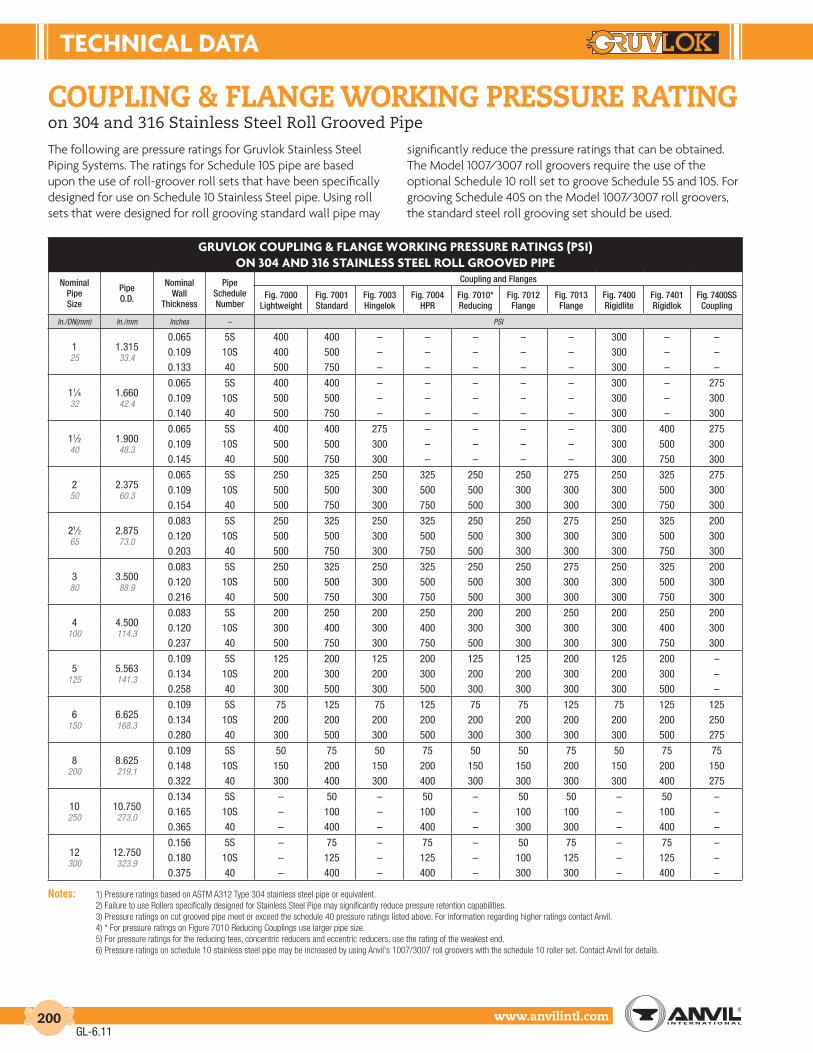
tEcHnIcAL dAtA
www.anvilintl.com200
GruVLoK couPLInG & FLAnGE WorKInG PrESSurE rAtInGS (PSI)on 304 And 316 StAInLESS StEEL roLL GrooVEd PIPE
Nominal Pipe Size
PipeO.D.
NominalWall
Thickness
PipeScheduleNumber
Coupling and Flanges
Fig. 7000Lightweight
Fig. 7001Standard
Fig. 7003Hingelok
Fig. 7004HPR
Fig. 7010*Reducing
Fig. 7012Flange
Fig. 7013Flange
Fig. 7400Rigidlite
Fig. 7401Rigidlok
Fig. 7400SSCoupling
In./DN(mm) In./mm Inches – PSI
125
1.31533.4
0.065 5S 400 400 – – – – – 300 – –0.109 10S 400 500 – – – – – 300 – –0.133 40 500 750 – – – – – 300 – –
11⁄432
1.66042.4
0.065 5S 400 400 – – – – – 300 – 2750.109 10S 500 500 – – – – – 300 – 3000.140 40 500 750 – – – – – 300 – 300
11⁄240
1.90048.3
0.065 5S 400 400 275 – – – – 300 400 2750.109 10S 500 500 300 – – – – 300 500 3000.145 40 500 750 300 – – – – 300 750 300
250
2.37560.3
0.065 5S 250 325 250 325 250 250 275 250 325 2750.109 10S 500 500 300 500 500 300 300 300 500 3000.154 40 500 750 300 750 500 300 300 300 750 300
21⁄265
2.87573.0
0.083 5S 250 325 250 325 250 250 275 250 325 2000.120 10S 500 500 300 500 500 300 300 300 500 3000.203 40 500 750 300 750 500 300 300 300 750 300
380
3.50088.9
0.083 5S 250 325 250 325 250 250 275 250 325 2000.120 10S 500 500 300 500 500 300 300 300 500 3000.216 40 500 750 300 750 500 300 300 300 750 300
4100
4.500114.3
0.083 5S 200 250 200 250 200 200 250 200 250 2000.120 10S 300 400 300 400 300 300 300 300 400 3000.237 40 500 750 300 750 500 300 300 300 750 300
5125
5.563141.3
0.109 5S 125 200 125 200 125 125 200 125 200 –0.134 10S 200 300 200 300 200 200 300 200 300 –0.258 40 300 500 300 500 300 300 300 300 500 –
6150
6.625168.3
0.109 5S 75 125 75 125 75 75 125 75 125 1250.134 10S 200 200 200 200 200 200 200 200 200 2500.280 40 300 500 300 500 300 300 300 300 500 275
8200
8.625219.1
0.109 5S 50 75 50 75 50 50 75 50 75 750.148 10S 150 200 150 200 150 150 200 150 200 1500.322 40 300 400 300 400 300 300 300 300 400 275
10250
10.750273.0
0.134 5S – 50 – 50 – 50 50 – 50 –0.165 10S – 100 – 100 – 100 100 – 100 –0.365 40 – 400 – 400 – 300 300 – 400 –
12300
12.750323.9
0.156 5S – 75 – 75 – 50 75 – 75 –0.180 10S – 125 – 125 – 100 125 – 125 –0.375 40 – 400 – 400 – 300 300 – 400 –
Notes: 1) Pressure ratings based on ASTM A312 Type 304 stainless steel pipe or equivalent. 2) Failure to use Rollers specifically designed for Stainless Steel Pipe may significantly reduce pressure retention capabilities. 3) Pressure ratings on cut grooved pipe meet or exceed the schedule 40 pressure ratings listed above. For information regarding higher ratings contact Anvil. 4) * For pressure ratings on Figure 7010 Reducing Couplings use larger pipe size. 5) For pressure ratings for the reducing tees, concentric reducers and eccentric reducers, use the rating of the weakest end. 6) Pressure ratings on schedule 10 stainless steel pipe may be increased by using Anvil's 1007/3007 roll groovers with the schedule 10 roller set. Contact Anvil for details.
The following are pressure ratings for Gruvlok Stainless Steel Piping Systems. The ratings for Schedule 10S pipe are based upon the use of roll-groover roll sets that have been specifically designed for use on Schedule 10 Stainless Steel pipe. Using roll sets that were designed for roll grooving standard wall pipe may
significantly reduce the pressure ratings that can be obtained. The Model 1007/3007 roll groovers require the use of the optional Schedule 10 roll set to groove Schedule 5S and 10S. For grooving Schedule 40S on the Model 1007/3007 roll groovers, the standard steel roll grooving set should be used.
couplinG & flanGe workinG pressure ratinGon 304 and 316 Stainless Steel Roll Grooved Pipe
GL-6.11

tEcHnIcAL dAtA
Intro
duct
ion
Coup
lings
Outle
tsFi
tting
sVa
lves
&
Acce
ssor
ies
High
Pres
sure
DI-L
OK®
Nipp
les
Plai
n-En
dFi
tting
sHD
PECo
uplin
gsSo
ck-It
®
Fitti
ngs
Stai
nles
sSt
eel M
etho
dRo
ll Gr
oove
rsIn
stal
latio
n&
Ass
embl
ySp
ecia
lCo
atin
gsDe
sign
Serv
ices
Tech
nica
lDa
taM
aste
r For
mat
3 Pa
rt Sp
ecs.
Pict
oria
lIn
dex
CTS
Copp
er
Syst
em
www.anvilintl.com 201
pipe supportWhen designing the hangers, supports and anchors for a grooved-end pipe system, the piping designer must consider certain unique characteristics of the grooved type coupling in addition to many universal pipe hanger and support design factors. As with any pipe system, the hanger or support system must provide for
1) the weight of the pipe, couplings, fluid and pipe system components;
2) reduce stresses at pipe joints; and
3) permit required pipe system movement to relieve stress.
The following factors should be considered when designing hangers and supports for a grooved-end pipe system.
PIPE HAnGEr SPAcInG:
The following charts show the maximum span between pipe hangers for straight runs of standard weight steel pipe filled with water or other similar fluids.
Do not use these values where critical span calculations are made or where there are concentrated loads between supports.
For straight runs without concentrated loads and where full linear movement is not required use the table on right.
For straight runs without concentrated loads and where full linearmovement IS required use the following tables.
* Spacing by ANSI-B31.1 Power Piping Code.
** Spacing by ANSI-B31.9 Building Service Piping Code, (1996 Edition), Fig. 921.1.3c, Table a, 250 psi and Fig. 921.1.3D, table a
*** Spacing by NFPA-13 Installation of Sprinkler Systems, (1999 Edition), Table 6-2.2.
HAnGEr SPAcInG - rIGId SYStEMS SuGGEStEd MAXIMuM SPAn BEtWEEn SuPPortS
Nominal Size
Steel Pipe Suggested Maximum Span Between Supports-Feet/Meters
Copper Tube
Water Service
Gas & Air ServiceWater Service Air Service
In./DNmm * ** *** * ** *** ** **
1 7 9 12 9 10 12 – –25 2.1 2.7 3.7 2.7 3.0 3.7
11⁄4 7 11 12 9 12 12 – –32 2.1 3.4 3.7 2.7 3.6 3.7
11⁄2 7 12 15 9 13 15 – –40 2.1 3.7 4.6 2.7 4 4.6
2 10 13 15 13 15 15 9 1250 3 4 4.6 4 4.6 4.6 2.7 3.6
21⁄2 11 15 15 14 17 15 9 1265 3.4 4.6 4.6 4.3 5.1 4.6 2.7 3.6
3 O.D. 11 15 15 14 17 15 – –
76.1 3.4 4.6 4.6 4.3 5.1 4.63 12 16 15 15 19 15 10 1480 3.7 4.8 4.6 4.6 5.7 4.6 3 4.2
31⁄2 13 18 15 15 21 15 – –90 4 5.4 4.6 4.6 6.3 4.6
4 14 18 15 17 21 15 12 17100 4.3 5.4 4.6 5.2 6.4 4.6 3.7 5.1
41⁄4 O.D. 14 18 15 17 19 15 – –
108.0 4.3 5.4 4.6 5.2 5.7 4.65 16 20 15 20 24 15 13 18
125 4.9 6.0 4.6 6.1 7.3 4.6 4 5.7
51⁄4 O.D. 15 18 15 19 22 15 – –
133.0 4.6 5.5 4.6 5.2 6.6 4.651⁄2 O.D. 16 19 15 20 24 15 – –
139.7 4.9 5.8 4.6 6.1 7.3 4.66 17 21 15 21 26 15 14 21
150 5.2 6.3 4.6 6.4 7.8 4.6 4.2 6.3
61⁄4 O.D. 16 20 15 20 24 15 – –
159.0 4.9 6.0 4.6 6.1 7.3 4.661⁄2 O.D. 17 21 15 21 25 15 – –
165.1 5.2 6.3 4.6 6.4 7.6 4.68 19 23 15 24 29 15 – –
200 5.8 6.9 4.6 7.3 8.7 4.6
10 19 25 15 24 33 15 – –250 5.8 7.5 4.6 7.3 9.9 4.6
12 23 26 15 30 36 15 – –300 7 7.8 4.6 9.1 10.8 4.6
14 23 26 15 30 37 15 – –350 7 7.8 4.6 9.1 11.1 4.6
16 27 26 15 35 40 15 – –400 8.2 7.8 4.6 10.7 12.0 4.6
18 27 27 15 35 42 15 – –450 8.2 8.1 4.6 10.7 12.6 4.6
20 30 27 15 39 45 15 – –500 9.1 8.1 4.6 11.9 13.5 4.6
24 32 26 15 42 48 15 – –600 9.8 7.8 4.6 12.8 14.7 4.6
HAnGEr SPAcInG - FLEXIBLE SYStEM, StEEL PIPE FuLL LInEAr MoVEMEnt IS rEQ’d
AVErAGE HAnGErS PEr PIPE LEnGtH EVEnLY SPAcEd
Nominal Pipe Size Range Pipe Length in Feet/Meters
In. 7 10 12 15 20 22 25 30 35 40
DNmm 2.1 3.3 3.7 4.6 6.1 6.7 7.6 9.1 10.7 12.2
1-2 1 2 2 2 3 3 4 4 5 625-50
21⁄2-4 1 1 2 2 2 2 2 3 4 465-100
5-24 1 1 1 2 2 2 2 3 3 3125-600
HAnGEr SPAcInG LInEAr MoVEMEnt not rEQ’dNominal Pipe Size Range
Maximum Span Between Supports
In./DNmm Feet/meters
1 725 2.1
11⁄4-2 1032-50 3.0
21⁄2-4 1265-100 3.7
5-8 14125-200 4.3
10-12 16250-300 4.9
14-16 18350-400 5.5
18-24 20450-600 6.1
GL-7.12

tEcHnIcAL dAtA
www.anvilintl.com202
pipe supportConsiderations for the Hanging or Supporting of Grooved Piping Systems
Grooved piping products have an excellent maintenance track record out in the field. Whenever there is a “perceived” problem with installed grooved product, a high percentage are often related to the hanging or supporting method or application chosen. Although supported very similarly to welded piping systems, a few considerations should be given to assure the proper selection and application of hangers and supports used on a grooved piping system such as Anvil’s Gruvlok® brand.
rEVIEW rEQuIrEMEntS And LoGIStIcSA variety of hangers and supports are typically used on grooved piping systems, ranging from a simple band hanger, clevis hanger, and trapeze supports to more intricate rack designs using structural steel or a mechanical framing/strut system. All of these are acceptable hanging or supporting methods but they are dependent on the project’s type, design and specification requirements. With this in mind, a vital first step is to refer to the project and code requirements when choosing the proper hanging or supporting method.
Project logistics is another consideration regardless of system type. Quite often hangers and supports are an afterthought on a project simply because the big-ticket items, such as labor, major equipment and schedule, are the focus of the project team. However, hangers and supports are one of the first components needed on a project since you cannot hang pipe without them.
In nearly every hanger or support assembly there are three components that make up the assembly. These components are an upper attachment (beam or structural attachment), intermediate attachment (rod, couplings, eye nuts, etc.) and the lower attachment (pipe clamps, U-bolts, trapezes). See accom-panying illustrations for examples of typical assemblies. All three components should arrive on the project site together and early. To save costly field labor hours, consideration might be given to having the hangers or supports pre-assembled by the manufacturer or fabricated in the contractor’s shop. Compo-nents can also be bundled and tagged by system or area of the project so they can be easily assembled and located on-site.
MAKE A MAtcHThe type of grooved coupling used on a project is the next consideration to choosing the correct hanger or support method. The proper maximum spacing allowables governed by project specifications, the applicable code and/or the hanger manufac-turer’s recommendations all must also be reviewed. Flexible couplings used on horizontal runs of pipe need to be supported at every coupling and usually require intermediate supports to satisfy the maximum spacing allowable requirements. Rigid couplings, on the other hand, can be hung or supported based on the maximum spacing requirements only. In addition, wherever there is a change in direction of the piping system a hanger or support is usually required immediately following that change in direction and then the system is hung or supported accordingly.
PrESSurE PoIntSystem pressurization should also be reviewed when choosing the proper hanging or support method. As the couplings are installed, the pipe ends can either be butted up tight to one another or a gap can exist. Once the system is pressurized, those areas or joints where the pipe ends are butted up tight and held by a grooved coupling can “pop” or grow to the maximum gap depending on the coupling chosen. The joint at a flexible grooved coupling can expand about 1⁄4" at each coupling whereas the joint at a rigid grooved coupling can grow about 3⁄32". If there is a long run of horizontal or vertical pipe with multiple joints the overall length of the system will grow depending upon which grooved coupling you have chosen.
For example, if you have a grooved piping system that is 400 ft. long there will be roughly 19 grooved joints (assuming 21 ft. lengths of pipe are used). If you multiply the number of joints by the growth of each joint you can determine the overall growth of the system due to pressurization. If it is a flexible system, 19 joints x .25" = 4.75" of overall growth. A rigid system would be 19 joints x .0938" = 1.78" of overall growth.
As one can see, this growth due to pressurization can have a significant impact on the hangers or supports used on a project. One way to avoid this growth is to install the grooved joints at full gap so that pressurization has no impact at testing or start up. If this is not possible, then periodic air pressurization as the system is installed will expand the grooved joints to full gap and the hangers or supports can be adjusted accordingly.
Hot And coLdThermal expansion is another important consideration when choosing hangers or supports for a grooved system. This is especially important on hot systems versus chilled systems since the amount of thermal expansion will be greater on hot systems as opposed to the thermal contraction that will occur on chilled systems. This is all due to the temperature variation from ambient conditions when the pipe is installed to operating conditions.
For example, if you again take 400 ft. of grooved piping, let us assume the system is heating hot water that will operate at 170°F. The pipe is installed under ambient conditions assumed to be at 70°F so you have a 100°F variation in temperature. At 70°F the pipe has a coefficient of thermal expansion of 0.0 in/ft but at 170°F the pipe has a coefficient of thermal expansion of 0.0076 in/ft. To determine the total thermal expansion of the pipe from ambient temperature to operating temperature you multiply the length of pipe by the coefficient of thermal expansion. In this case 400 ft. x 0.0076 in/ft. = 3.04 in. In other words the pipe has grown in length over 3 inches because of the thermal expansion.
This is significant growth especially if there is a change of direction at the end of the 400 ft. pipe run or there are branch lines coming off the main run. If this thermal growth exceeds the allowable deflection of a grooved joint, especially where a change of direction or a branch line connects, then problems could occur.
GL-7.12

tEcHnIcAL dAtA
Intro
duct
ion
Coup
lings
Outle
tsFi
tting
sVa
lves
&
Acce
ssor
ies
High
Pres
sure
DI-L
OK®
Nipp
les
Plai
n-En
dFi
tting
sHD
PECo
uplin
gsSo
ck-It
®
Fitti
ngs
Stai
nles
sSt
eel M
etho
dRo
ll Gr
oove
rsIn
stal
latio
n&
Ass
embl
ySp
ecia
lCo
atin
gsDe
sign
Serv
ices
Tech
nica
lDa
taM
aste
r For
mat
3 Pa
rt Sp
ecs.
Pict
oria
lIn
dex
CTS
Copp
er
Syst
em
www.anvilintl.com 203
Thermal growth cannot be stopped. It can only be controlled by the use of anchors and expansion joints or expansion loops.
It is also important to hang or support the pipe with rolls or slides and use guides to control the thermal expansion of the pipe into an expansion joint or expansion loop. The use of static hangers, such as clevis hangers, should not be considered on pipe that is thermally expanding. When using trapeze hangers for multiple systems it is important to have “like” systems on the trapeze, that is, systems that are operating near the same temperature. If you combine hot systems with cold systems on a trapeze, the thermal expansion of the hot system can cause the trapeze to possibly twist and fail or excessive stress could be induced on the grooved joints on all of the systems on the trapeze. Hot systems should be hung or supported indepen-dently of cold or ambient systems or a means should be provided, such as pipe rolls or pipe slides, to allow the hot systems to thermally expand on the trapeze.
If the pipe is a vertical riser then consideration must be given to the use of spring hangers to allow the pipe to grow vertically up or down depending upon how the pipe is anchored while still supporting the pipe. Vertical pipe thermally expands the same amount as horizontal pipe and this has to be taken into consideration relating to supports, expansion joints or expansion loops. If the vertical pipe is supported by friction/riser clamps only and the pipe expands vertically upward, the clamps will grow with the pipe off the penetration or supporting structure and no longer provide support. If the growth is downward, the friction clamps resting on the penetration or supporting structure can either fail or the pipe may overcome the friction force and push it’s way through the clamp as the pipe thermally expands downward. In either case the clamps are no longer supporting the pipe as intended and this may induce excessive stress on the grooved joints.
Whether it is horizontal or vertical grooved pipe, growth of the piping system due to pressurization and thermal expansion must be considered. On hot systems, both must be taken into account and added together to determine the overall growth of the system and the effect on the hangers or supports that are used. In the previous examples, pressurization expansion on the 400 ft. run of pipe was 4.75" for a flexible joint system and 1.78" for a rigid joint system and the thermal expansion was 3.04". Adding these combinations together would result in a total pipe growth of 7.79" for a flexible system or 4.82" for a rigid system, regardless of the horizontal or vertical orientation of the pipe. Again, this is a significant amount of growth relating to hangers and supports and the resulting stresses induced on grooved joints.
conSIdEr SoME rEStrAIntAlthough grooved systems in seismic zones perform extremely well, consideration should be given to how a grooved system is seismically restrained. If you have growth due to pressurization and/or thermal expansion consideration should be given on how to restrain the system while still allowing growth to occur. Seismic restraints in the longitudinal direction of a long pipe run may restrict the growth of the pipe inducing stresses into the grooved couplings. Seismic restraints in the lateral direction should have little impact on expansion except where the system has a change in direction. If the seismic restraints are placed laterally after a change in direction at the end of a long run of pipe, the expansion of the long pipe run may be restricted and this could induce excessive stress into the grooved joints.
By reviewing the couplings to be used on a project, pressurization, thermal expansion and seismic restraints, one can best determine the proper selection and application of hangers and supports for a grooved piping system. This will, in turn, help ensure that grooved piping systems will continue to enjoy a solid reputation in the areas of maintenance and downtime.
pipe supportConsiderations for the Hanging or Supporting of Grooved Piping Systems
upper
intermediate
lower
Clevis Hanger Assembly
upper
intermediate
lower
Double Bolt PipeClamp Assembly
upper
intermediate
lower
Trapeze Assembly
upper
intermediate
lower
Spring Riser Hanger Assembly
GL-6.11

tEcHnIcAL dAtA
www.anvilintl.com204
L2
D2
D1
CR2R1
L3
L1
L1L2
couplinG flexibility:
The grooved coupling’s capability to allow angular and rotational movement within the coupling joint must be considered when deciding hanger and support locations. Spring hangers and supports providing for movement in more than one plane are often used to allow the pipe system to move without introducing additional stress into the pipe system.
EXAMPLE 1This example demonstrates the need for each pipe length in a grooved system to be supported. The sag due to the flexibility of the Gruvlok joint could be eliminated with the proper positioning of hangers on both pipe segments “L1” and “L2”.
EXAMPLE 2This illustrates the effect of pump oscillation on a piping system. A spring hanger should be used to support the pipe section and also respond to the induced vibrations. The couplings in the horizontal run above the riser, should accommodate the deflection without transmitting bending stresses through the pipe system.
PrESSurE tHruStS:Gruvlok couplings react to the application of system pressure and restrain the pipe ends from separation due to the pressure force. However, the coupling joint may not be in the self-restraining configuration prior to the application of system pressure. The Gruvlok coupling does not restrain adjacent pipe sections from separation due to pressure forces until the coupling key sections engage the groove walls.
Random flexible coupling joint installation will produce installed coupling conditions ranging from pipe ends full butted to fully separated to the maximum available gap. Thus, only after system pressurization will the self-restraining function of the coupling be in effect.
The designer must account for the movement to be encountered when the system is pressurized and the joints are fully separated. Anchor and guide positions must be defined to direct the pipe joint movement that it is not detrimental to the pipe system.
Examples of the effect of pressure thrust are shown in the following illustrations.
EXAMPLE 1The coupling joints have been installed butted or partially open. When pressurized the pipe ends in the coupling joints will separate to the maximum amount permitted by the coupling design.
EXAMPLE 2In the system shown here, the pipe will move and deflect at the elbow joint due to pressure thrust.
The pipe designer must assure himself that the system has the capability of deflecting sufficiently to absorb this movement without introducing additional stresses into the pipe system. In the deflected condition shown, temperature increases would produce further expansion of the pipe system thus increasing the deflection.
EXAMPLE 3To restrain this system provide a pressure thrust anchor at “R1” to resist the pressure thrust acting through the tee “D1” at the cap “C”. Provide a hanger at Point “R2”, or a base support at Point “D2” to support the vertical column. If the offsets L1, L2, and L3 are of adequate length to handle expected pipe movements,no additional anchoring is required.Thermal movement of the pipesystem should alsobe considered, andintermediate anchors located asrequired, to direct the pipe movementso as to prevent introducing bendingstresses into the system.
System With No Pressure
System Pressurized
SUFFICIENT LENGTH TO OFFSETPRESSURE THRUST
The coupling key sections will make contact with the groove walls and restrain the pipe from further separation.
The movement at each coupling joint will add with all other joints and produce ∆L.
GL-6.11

tEcHnIcAL dAtA
Intro
duct
ion
Coup
lings
Outle
tsFi
tting
sVa
lves
&
Acce
ssor
ies
High
Pres
sure
DI-L
OK®
Nipp
les
Plai
n-En
dFi
tting
sHD
PECo
uplin
gsSo
ck-It
®
Fitti
ngs
Stai
nles
sSt
eel M
etho
dRo
ll Gr
oove
rsIn
stal
latio
n&
Ass
embl
ySp
ecia
lCo
atin
gsDe
sign
Serv
ices
Tech
nica
lDa
taM
aste
r For
mat
3 Pa
rt Sp
ecs.
Pict
oria
lIn
dex
CTS
Copp
er
Syst
em
www.anvilintl.com 205
EXAMPLE 4Anchor at “A” to support weight of vertical water column. Use spring hanger at “D” and “E” to allow movement of vertical piping.
Anchors at “B” and “C” if offsets at L1 and L2 are insufficiently long to handle expected pipe movements.
LAtErAL rEStrAInt
EXAMPLE 5A grooved coupling joint installed in a partially deflected condition between anchor locations will deflect to its fully deflected condition when pressurized. Hangers and supports must be selected with consideration of the hanger’s capability to provide lateral restraint.
Light duty hangers, while acceptable in many installations, may deflect against the application of lateral forces and result in “snaking” conditions of the pipe system.
rISEr dESIGn:Risers assembled with Gruvlok Flexible couplings are generally installed in either of two ways. In the most common method, the pipe ends are butted together within the coupling joint. Note that when installing risers, the gasket is first placed onto the lower pipe and rolled back away from the pipe end prior to positioning the upper pipe. Anchoring of the riser may be done prior to pressurization with the pipe ends butted or while pressurized, when, due to pressure thrust, the pipe ends will be fully separated.
An alternative method or riser installation is to place a metal spacer of a predetermined thickness, between the pipe ends when an additional length of pipe is added to the riser stack. The upper pipe length is anchored, the spacer removed and the coupling is then installed. This method creates a predetermined gap at each pipe joint which can be utilized in pipe systems where thermal movement is anticipated and in systems with rigid (threaded, welded, flanged) branch connections where shear forces due to pressure thrust could damage the rigid connections.
The following examples illustrate methods of installing commonly encountered riser designs.
rISErS WItHout BrAncH connEctIonSInstall the riser with the pipe ends butted.
Locate an anchor at the base of the riser (A) to support the total weight of the pipe, couplings and fluid. Provide pipe guides on every other pipe length, as a minimum, to prevent possible deflection of the pipe line at the coupling joints as the riser expands due to pressure thrust or thermal growth. Note that no intermediate anchors are required.
When the system is pressurized the pipe stack will “grow” due to pressure thrust which causes maximum separation of pipe ends within the couplings. The maximum amount of stack growth can be predetermined (see Linear Movement). In this example the pipe length “L” at the top of the riser must be long enough to permit sufficient deflection (see Angular Movement) to accommodate the total movement “M” from both pressure thrust and thermal gradients.
rISErS WItH BrAncH connEctIonSInstall the riser with the predetermined gap method. Anchor the pipe at or near the base with a pressure thrust anchor “A” capable of supporting the full pressure thrust, weight of pipe and the fluid column. Anchor at “B” with an anchor capable of withstanding full pressure thrust at the top of the riser plus weight of pipe column. Place intermediate anchors “C” as shown, between anchors “A” and “B”. Also place intermediate clamps at every other pipe length as a minimum.
When this system is pressurized, the pipe movement due to pressure thrust will be strained and there will be no shear forces acting at the branch connections.
couplinG flexibility (cont.)
L 2
L1E
C
A
D
B
VERTICALCOLUMN
VERTICALCOLUMN
HORIZONTAL RUN
System with no pressurepartially deflected
System pressurizedfully deflected
A
LM
C
C
B
C
A
GL-6.11

tEcHnIcAL dAtA
www.anvilintl.com206
BULL-PLUG 7075
CAP 7074
CLAMP-T
GROOVED OUTLET 7046
FEMALE 7044 THREADED 7045 OUTLET
CLAMP-T-CROSS
GROOVED 7048 OUTLETS
FEMALE THREADED 7047 OUTLETS
COUPLINGS 7000
STRAIGHT
7001
7003
7004
7011
7400
REDUCING
7401
7010
CROSS 7068
ELBOW
90° 7050
45° 7051
TURNED-DOWN –
TURNED-UP –
ELBOW 90° ADAPTER 7055
45° ADAPTER 7056
EXPANSION JOINT 7092
GRUVLOK 7012 FLANGE 7013
LATERAL 45°
STRAIGHT 7069
REDUCING 7070
COMPONENT FIG. NO. SYMBOL COMPONENT FIG. NO. SYMBOL
REDUCER
CONCENTRIC 7072
ECCENTRIC 7073
TEE
STRAIGHT 7060
REDUCING 7061
TURNED-DOWN –
TURNED-UP –
TRUE-WYE 7071
GRUVLOK SERIES BUTTERFLY 7700 BALL VALVE 7500 CHECK VALVE 7800
FPT
42
112 FPT
FPT
42
112
6 4
6 6
4
64
6 4
6 6
4
GFMATING
FLG
MPT
MPT
draftinG symbols for Gruvlok®
pipinG systems
All fittings are shown with couplings attached at the grooved-ends.
GL-6.11

tEcHnIcAL dAtA
Intro
duct
ion
Coup
lings
Outle
tsFi
tting
sVa
lves
&
Acce
ssor
ies
High
Pres
sure
DI-L
OK®
Nipp
les
Plai
n-En
dFi
tting
sHD
PECo
uplin
gsSo
ck-It
®
Fitti
ngs
Stai
nles
sSt
eel M
etho
dRo
ll Gr
oove
rsIn
stal
latio
n&
Ass
embl
ySp
ecia
lCo
atin
gsDe
sign
Serv
ices
Tech
nica
lDa
taM
aste
r For
mat
3 Pa
rt Sp
ecs.
Pict
oria
lIn
dex
CTS
Copp
er
Syst
em
www.anvilintl.com 207
pipe-preparation:
To create a Gruvlok pipe joint, all pipe must be prepared to receive a Gruvlok coupling or other Gruvlok pipe system components. Required pipe preparations may include: grooving or cleaning the pipe ends, or cutting a hole in the pipe wall.
For grooved-end joints, pipe may be grooved by either of two methods; cut or roll grooving. Branch outlet connections require a properly sized and correctly located hole to be cut into the pipe. Sock-it connections require cleaning of the pipe end. Gruvlok plain-end pipe couplings require that the pipe be free of burrs and other sharp projections which could damage the gasket; grooving is not required.
Gruvlok pipe grooving and hole cutting machines are available in a wide variety of designs to meet specific or general requirements. Gruvlok roll grooving machines produce a groove to proper dimensional tolerances, concentric with the pipe O.D., even on out-of-round pipe. Gruvlok hole cutting tools properly center holes for correct assembly of Gruvlok branch outlet components.
Cut grooving is intended for use with standard and heavier wall pipe. Cut grooving produces a groove in the pipe wall by removing metal from the pipe O.D. The groove removes less than one half of the pipe wall and does not cut as deeply into the pipe wall as do standard pipe threads. The square cut edge of the groove allows for the full expansion, contraction, and deflection capabilities of the Gruvlok coupling.
cut GroovinG:
roll GroovinG:
Roll grooving does not remove metal. Instead, metal is displaced while a groove is formed into the outer surface of the pipe wall. The groove configuration has slightly rounded edges resulting in a less flexible joint than a cut groove joint. This reduces available pipe joint movement by 50% over cut grooved coupling joints. Roll grooving is commonly used on a wide range of pipe thicknesses up to 0.375" wall steel pipe and sizes to 24" O.D.
Cut Grooving
Depth of Cut Groovevs. Thread
Volume of Metal RemovedCut Groove vs. Threaded
Roll Grooving
The I.D. “dimple" formed from roll grooving reduces the I.D. (on an average) less than 2%.
Roll Groove
Cut Groove
Available MovementRoll Groove vs. Cut Groove
GL-7.12

tEcHnIcAL dAtA
www.anvilintl.com208
PIPE toLErAncES
SizeSchedule 10 & 40 Min.
O.D.XL Min.
O.D.Nom O.D. Max. O.D.DN/mm In./mm In./mm In./mm In./mm
1 1.315 1.325 1.295 1.28525 33.4 33.6 32.9 32.611⁄4 1.660 1.670 1.642 1.63032 42.2 42.4 41.7 41.411⁄2 1.900 1.910 1.882 1.87540 48.3 48.5 47.8 47.62 2.375 2.385 2.357 2.35250 60.3 60.6 59.9 59.721⁄2 2.875 2.904 2.846 2.83765 73.0 73.8 72.3 72.1
cLAMP-t InStALLAtIon
Branch Size
Hole Dimensions Surface Prep. “A”Hole Saw Size Max. Perm. Diameter
DN/mm In./mm In./mm In./mm
1⁄2, 3⁄4, 1 11⁄2 15⁄8 31⁄215, 20, 25 38.1 41.3 88.911⁄4, 11⁄2 2 21⁄8 432, 40 50.8 54.0 101.6
2 21⁄2 25⁄8 41⁄250 63.5 66.7 114.321⁄2 23⁄4 27⁄8 43⁄465 69.9 73.0 120.73 31⁄2 35⁄8 51⁄280 88.9 92.1 139.74 41⁄2 45⁄8 61⁄2
100 114.3 117.5 165.1
pipe-preparation:
branch outlet pipe: clamp-t®
Clamp-T installations require the cutting of a hole through the pipe wall. The hole must be properly sized and located on the centerline of the pipe to assure reliable performance of the Clamp-T gaskets.
After the hole has been cut into the pipe wall, any burrs and sharp or rough edges must be removed from the hole. The outside pipe surfaces within 5/8" of the hole must be clean and smooth. Any scale, projections or indentation which might effect the gasket sealing on the pipe must be removed. The surface around the entire circumference of the pipe within the “A” dimension in the charts must be free from dirt, scale, or projections which might effect the proper assembly of the Clamp-T.
sock-it®
For Sock-It Fittings, the pipe ends must be square cut as measured from a true square line.
The maximum allowable tolerance is 0.030" (0.76mm) for all sizes. Any sharp edges, burrs, etc. left on the pipe from cutting must be removed. If these are not removed, they may damage the gasket as the pipe is inserted into the Sock-It Fitting.
After cutting, pipe ends must be completely cleaned a minimum of 1" (25.4mm) back from the pipe end to remove all pipe coating, weld beads, rust, sharp projections, etc., which might effect gasket sealing integrity.
AccEPtABLE PIPE End conFIGurAtIon
notE: When Allied XL pipe is used it is necessary only to remove sharp edges and burrs at the end of the pipe. No additional cleaning is required.
rouGhneck®
A
5⁄8"
Square cut pipe with O.D.burr & sharp edge removedis preferred configuration.
Beveled pipe. Bevel notto exceed 1⁄16".
Soft pipe when roll cut maybe swaged inward. Swagedportion not to exceed 3⁄16"
Remove Burr& Sharp Edge
30 or 45
1⁄32" to 1⁄16" 3⁄16" Max.
Plain-End pipe for use with Fig. 7005 Roughneck Couplings must be free of any notches, bumps, weld bead, score marks, etc. for at least 11/2" (38 mm) back from the pipe end to provide a smooth sealing surface for the gasket. Pipe ends (plain or beveled end) must be square cut as measured from a true square line with the maximum allowable tolerance as follows: 0.030" (0.7 mm) for 2" through 3"; 0.045 (1.1 mm) for 4" through 6"; and 0.060"
(1.5 mm) for 8" sizes. The nominal outside diameter of pipe should not vary more than ±1% for sizes up to 21/2", +1%-1/32” for sizes 3"-5"; +1/16”-1/32" for sizes 6" and larger. Pipe ends must be marked a distance of 1" from the pipe end for Sizes 2"-4" and 11/4" from the pipe end for Sizes 5"-8" as a guide for centering of the gasket on the pipe ends.
unAccEPtABLE
The sharp O.D. edge left by different methods of cutting pipe must be removed. If this sharp edge is not removed, it may damage the gasket as the pipe is inserted into the Sock-It Fitting.
Excessive chamfer on I.D.will tend to cut gasket
during assembly.
Abrasive wheels & sawsleave edge burrs especiallypronounced on one side.
Dull wheel cutter produces araised ridge at the pipe O.D.giving an oversize diameter.
GL-6.11

tEcHnIcAL dAtA
Intro
duct
ion
Coup
lings
Outle
tsFi
tting
sVa
lves
&
Acce
ssor
ies
High
Pres
sure
DI-L
OK®
Nipp
les
Plai
n-En
dFi
tting
sHD
PECo
uplin
gsSo
ck-It
®
Fitti
ngs
Stai
nles
sSt
eel M
etho
dRo
ll Gr
oove
rsIn
stal
latio
n&
Ass
embl
ySp
ecia
lCo
atin
gsDe
sign
Serv
ices
Tech
nica
lDa
taM
aste
r For
mat
3 Pa
rt Sp
ecs.
Pict
oria
lIn
dex
CTS
Copp
er
Syst
em
www.anvilintl.com 209
COLUMN 1 - Nominal IPS Pipe size. Nominal ISO Pipe size.
COLUMN 2 - IPS outside diameter. ISO outside diameter.
COLUMN 3 - Gasket seat must be free from scores, seams, chips, rust or scale which may interfere with proper sealing of the gasket. Gasket seat width (Dimension A) is to be measured from the pipe end to the vertical flank in the groove wall.
COLUMN 4 - Groove width (Dimension B) is to be measured between vertical flank of the groove size walls.
COLUMN 5 - The groove must be of uniform depth around the entire pipe circumference. (See column 6).
COLUMN 6 - Groove depth: for reference only. Groove must conform to the groove diameter “C” listed in column 5.
COLUMN 7 - Minimum allowable wall thickness which may be roll grooved.
COLUMN 8 - Maximum allowable pipe end flare diameter. Measured at the most extreme pipe end diameter of the gasket seat area.
Out of roundness: Difference between maximum O.D. and minimum O.D. measured at 90° must not exceed total O.D. tolerance listed (refer-ence column 2).
For IPS pipe, the maximum allowable tolerance from square cut ends is 0.03" for 1" thru 31⁄2"; 0.045" for 4" thru 6"; and 0.060" for sizes 8" and above measured from a true square line.
For ISO size pipe, the maximum allowable tolerance from square cut ends is 0.75mm for sizes 25mm-80mm; 1.15mm for sizes 100mm-150mm; and 1.50mm for sizes 200mm and above, measured from a true square line.
Beveled-End Pipe in conformance with ANSI B16.25 (371⁄2°) is acceptable, however square cut is preferred. Seams must be ground flush with the pipe O.D. and ID prior to roll grooving. Failure to do so may result in damage to the roll groov-ing machine and unacceptable roll grooves may be produced.
Weld Seams must be ground flush with the pipe O.D. and ID prior to roll grooving. Failure to do so may result in damage to the roll grooving machine and unacceptable roll grooves may be produced.
▼ “A” tolerance +0.030" / -0.060" (+0.77 / -1.54 mm)
roll Groove specifications
NOTE: VdS - Roll Grooving Approval Specifications, see the Technical Data/Install Instructions section on Anvil’s web site - www.anvilintl.com
GruVLoK StAndArd roLL GrooVE SPEcIFIcAtIon For StEEL & otHEr IPS or ISo SIZE PIPE
-1- -2- -3- -4- -5- -6- -7- -8-
Nominal Pipe Size
O.D. “A” ±0.030/ ±0.76
“B” ±0.030/ ±0.76
“C” Actual
“C” Tol. +0.000
“D” (Ref. Only)
“T” Min. Allow.
Wall Thick
Max. Flare Dia.Actual Tolerance
In./DN(mm) In./mm +In./mm -In./mm In./mm In./mm In./mm -In./mm In./mm In./mm In./mm
1 1.315 +0.028 -0.015 0.625 0.281 1.190 -0.015 0.063 0.065 1.43025 33.4 +0.71 -0.38 15.88 7.14 30.23 -0.38 1.60 1.7 36.3
11⁄4 1.660 +0.029 -0.016 0.625 0.281 1.535 -0.015 0.063 0.065 1.77032 42.2 +0.74 -0.41 15.88 7.14 38.99 -0.38 1.60 1.7 45.0
11⁄2 1.900 +0.019 -0.019 0.625 0.281 1.775 -0.015 0.063 0.065 2.01040 48.3 +0.48 -0.48 15.88 7.14 45.09 -0.38 1.60 1.7 51.1
2 2.375 +0.024 -0.024 0.625 0.344 2.250 -0.015 0.063 0.065 2.48050 60.3 +0.61 -0.61 15.88 8.74 57.15 -0.38 1.60 1.7 63.0
21⁄2 2.875 +0.029 -0.029 0.625 0.344 2.720 -0.018 0.078 0.083 2.98065 73.0 +0.74 -0.74 15.88 8.74 69.09 -0.46 1.98 2.1 75.7
3 O.D. 2.996 +0.030 -0.030 0.625 0.344 2.845 -0.018 0.076 0.083 3.10076.1 76.1 +0.76 -0.76 15.88 8.74 72.26 -0.46 1.93 2.1 78.7
3 3.500 +0.035 -0.031 0.625 0.344 3.344 -0.018 0.078 0.083 3.60080 88.9 +0.89 -0.79 15.88 8.74 84.94 -0.46 1.98 2.1 91.4
31⁄2 4.000 +0.040 -0.031 0.625 0.344 3.834 -0.020 0.083 0.083 4.10090 101.6 +1.02 -0.79 15.88 8.74 97.38 -0.51 2.11 2.1 104.1
41⁄4 O.D. 4.250 +0.042 -0.031 0.625 0.344 4.084 -0.020 0.083 0.083 4.350108.0 108.0 +1.07 -0.79 15.88 8.74 103.73 -0.51 2.11 2.1 110.5
4 4.500 +0.045 -0.031 0.625 0.344 4.334 -0.020 0.083 0.083 4.600100 114.3 +1.14 -0.79 15.88 8.74 110.08 -0.51 2.11 2.1 116.8
51⁄4 O.D. 5.236 +0.052 -0.031 0.625 0.344 5.084 -0.020 0.076 0.109 5.350133.0 133.0 +1.32 -0.79 15.88 8.74 129.13 -0.51 1.93 2.8 135.9
51⁄2 O.D. 5.500 +0.055 -0.031 0.625 0.344 5.334 -0.020 0.083 0.109 5.600139.7 139.7 +1.40 -0.79 15.88 8.74 135.48 -0.51 2.11 2.8 142.2
5 5.563 +0.056 -0.031 0.625 0.344 5.395 -0.022 0.084 0.109 5.660125 141.3 +1.42 -0.79 15.88 8.74 137.03 -0.56 2.13 2.8 143.8
61⁄4 O.D. 6.259 +0.063 -0.031 0.625 0.344 6.084 -0.022 0.088 0.109 6.350159.0 159.0 +1.60 -0.79 15.88 8.74 154.53 -0.56 2.24 2.8 161.3
61⁄2 O.D. 6.500 +0.063 -0.031 0.625 0.344 6.334 -0.022 0.085 0.109 6.600165.1 165.1 +1.60 -0.79 15.88 8.74 160.88 -0.56 2.16 2.8 167.6
6 6.625 +0.063 -0.031 0.625 0.344 6.455 -0.022 0.085 0.109 6.730150 168.3 +1.60 -0.79 15.88 8.74 163.96 -0.56 2.16 2.8 170.9
8 8.625 +0.063 -0.031 0.750 0.469 8.441 -0.025 0.092 0.109 8.800200 219.1 +1.60 -0.79 19.05 11.91 214.40 -0.64 2.34 2.8 223.5
10 10.750 +0.063 -0.031 0.750 0.469 10.562 -0.027 0.094 0.134 10.920250 273.1 +1.60 -0.79 19.05 11.91 268.27 -0.69 2.39 3.4 277.4
12 12.750 +0.063 -0.031 0.750 0.469 12.531 -0.030 0.109 0.156 12.920300 323.9 +1.60 -0.79 19.05 11.91 318.29 -0.76 2.77 4.0 328.2
14 O.D. 14.000 +0.063 -0.031 0.938 0.469 13.781 -0.030 0.109 0.156 14.100355.6 355.6 +1.60 -0.79 23.83 11.91 350.04 -0.76 2.77 4.0 358.1
16 O.D. 16.000 +0.063 -0.031 0.938 0.469 15.781 -0.030 0.109 0.165 16.100406.4 406.4 +1.60 -0.79 23.83 11.91 400.84 -0.76 2.77 4.2 408.9
18 O.D. 18.000 +0.063 -0.031 1.000 0.469 17.781 -0.030 0.109 0.165 18.160457.2 457.2 +1.60 -0.79 25.40 11.91 451.64 -0.76 2.77 4.2 461.3
20 O.D. 20.000 +0.063 -0.031 1.000 0.469 19.781 -0.030 0.109 0.188 20.160508.0 508.0 +1.60 -0.79 25.40 11.91 502.44 -0.76 2.77 4.8 512.1
24 O.D. 24.000 +0.063 -0.031 1.000 0.500 23.656 -0.030 0.172 0.218 24.200609.6 609.6 +1.60 -0.79 25.40 12.70 600.86 -0.76 4.37 5.5 614.7
30 O.D. 30.000 +0.093 -0.031 1.750 ▼ 0.625 29.500 -0.063 0.250 0.250 30.200762.0 762.0 2.36 0.79 44.45 15.88 749.30 1.60 6.35 6.35 761.1
TB
DC
OD
Fla
re
A
GL-6.11

tEcHnIcAL dAtA
www.anvilintl.com210
COLUMN 1 - Nominal IPS Pipe size. Nominal ISO Pipe size.
COLUMN 2 - IPS outside diameter. ISO outside diameter.
COLUMN 3 & 4 - Gasket seat must be free from scores, seams, chips, rust or scale which may interfere with proper coupling assembly.
COLUMN 5 - The groove must be of uniform depth around the entire pipe circumference. (See column 6).
COLUMN 6 - Groove depth: for reference only. Groove must conform to the groove diameter “C” listed in column 5.
COLUMN 7 - Minimum allowable wall thickness which may be cut grooved.
Out of roundness: Difference between maximum O.D. and minimum O.D. measured at 90° must not exceed total O.D. tolerance listed.
For IPS pipe, the maximum allowable tolerance from square cut ends is 0.03" for 1" thru 31⁄2"; 0.045" for 4" thru 6”; and 0.060" for sizes 8" and above measured from a true square line.
For ISO size pipe, the maximum allowable tolerance from square cut ends is 0.75mm for sizes 25mm-80mm; 1.15mm for sizes 100mm- 150mm; and 1.50mm for sizes 200mm and above, measured from a true square line.
Beveled-End Pipe in conformance with ANSI B16.25 (371⁄2°) is acceptable, however square cut is preferred.
not to be used with End Guard gaskets.
▼ “A” tolerance +0.030" / -0.060" (+0.77 / -1.54 mm)
cut Groove specifications
GruVLoK StAndArd cut GrooVE SPEcIFIcAtIon For StEEL & otHEr IPS or ISo SIZE PIPE
-1- -2- -3- -4- -5- -6- -7-
Nominal IPS Pipe
Size
O.D. Gasket Seat “A” ±0.030 ±0.76
Groove Width “B”
±0.030 ±0.76
Groove Diameter “C”
Actual Groove
Depth “D” (Ref. Only)
Min. Allow. Wall
Thick. “T” Actual Tolerance Actual Tol.+0.000
In./DN(mm) In./mm +In./mm -In./mm In./mm In./mm In./mm -In./mm In./mm In./mm
1 1.315 +0.028 -0.015 0.625 0.312 1.190 -0.015 0.062 0.13325 33.4 +0.71 -0.38 15.88 7.92 30.23 -0.38 1.6 3.4
11⁄4 1.660 +0.029 -0.016 0.625 0.312 1.535 -0.015 0.062 0.14032 42.2 +0.74 -0.41 15.88 7.92 38.99 -0.38 1.6 3.6
11⁄2 1.900 +0.019 -0.019 0.625 0.312 1.775 -0.015 0.062 0.14540 48.3 +0.48 -0.48 15.88 7.92 45.09 -0.38 1.6 3.7
2 2.375 +0.024 -0.024 0.625 0.312 2.250 -0.015 0.062 0.15450 60.3 +0.61 -0.61 15.88 7.92 57.15 -0.38 1.6 3.9
21⁄2 2.875 +0.029 -0.029 0.625 0.312 2.720 -0.018 0.078 0.18765 73.0 +0.74 -0.74 15.88 7.92 69.09 -0.46 2.0 4.8
3 O.D. 2.996 +0.030 -0.030 0.625 0.312 2.845 -0.018 0.076 0.18876.1 76.1 +0.76 -0.76 15.88 7.92 72.26 -0.46 1.9 4.8
3 3.500 +0.035 -0.031 0.625 0.312 3.344 -0.018 0.078 0.18880 88.9 +0.89 -0.79 15.88 7.92 84.94 -0.46 2.0 4.8
31⁄2 4.000 +0.040 -0.031 0.625 0.312 3.834 -0.020 0.083 0.18890 101.6 +1.02 -0.79 15.88 7.92 97.38 -0.51 2.1 4.8
41⁄4 O.D. 4.250 +0.042 -0.031 0.625 0.375 4.084 -0.020 0.083 0.203108.0 108.0 +1.07 -0.79 15.88 9.53 103.73 -0.51 2.1 5.2
4 4.500 +0.045 -0.031 0.625 0.375 4.334 -0.020 0.083 0.203100 114.3 +1.14 -0.79 15.88 9.53 110.08 -0.51 2.1 5.2
51⁄4 O.D. 5.236 +0.052 -0.031 0.625 0.375 5.084 -0.020 0.076 0.203133.0 133.0 +1.32 -0.79 15.88 9.53 129.13 -0.51 1.9 5.2
51⁄2 O.D. 5.500 +0.055 -0.031 0.625 0.375 5.334 -0.020 0.083 0.203139.7 139.7 +1.40 -0.79 15.88 9.53 135.48 -0.51 2.1 5.2
5 5.563 +0.056 -0.031 0.625 0.375 5.395 -0.022 0.084 0.203125 141.3 +1.42 -0.79 15.88 9.53 137.03 -0.56 2.1 5.2
61⁄4 O.D. 6.259 +0.063 -0.031 0.625 0.375 6.084 -0.022 0.088 0.249159.0 159.0 +1.60 -0.79 15.88 9.53 154.53 -0.56 2.2 6.3
61⁄2 O.D. 6.500 +0.063 -0.031 0.625 0.375 6.334 -0.022 0.085 0.219165.1 165.1 +1.60 -0.79 15.88 9.53 160.88 -0.56 2.2 5.6
6 6.625 +0.063 -0.031 0.625 0.375 6.455 -0.022 0.085 0.219150 168.3 +1.60 -0.79 15.88 9.53 163.96 -0.56 2.2 5.6
8 8.625 +0.063 -0.031 0.750 0.437 8.441 -0.025 0.092 0.238200 219.1 +1.60 -0.79 19.05 11.10 214.40 -0.64 2.3 6.1
10 10.750 +0.063 -0.031 0.750 0.500 10.562 -0.027 0.094 0.250250 273.1 +1.60 -0.79 19.05 12.70 268.27 -0.69 2.4 6.4
12 12.750 +0.063 -0.031 0.750 0.500 12.531 -0.030 0.109 0.279300 323.9 +1.60 -0.79 19.05 12.70 318.29 -0.76 2.8 7.1
14 O.D. 14.000 +0.063 -0.031 0.938 0.500 13.781 -0.030 0.109 0.281355.6 355.6 +1.60 -0.79 23.83 12.70 350.04 -0.76 2.8 7.1
16 O.D. 16.000 +0.063 -0.031 0.938 0.500 15.781 -0.030 0.109 0.312406.4 406.4 +1.60 -0.79 23.83 12.70 400.84 -0.76 2.8 7.9
18 O.D. 18.000 +0.063 -0.031 1.000 0.500 17.781 -0.030 0.109 0.312457.2 457.2 +1.60 -0.79 25.40 12.70 451.64 -0.76 2.8 7.9
20 O.D. 20.000 +0.063 -0.031 1.000 0.500 19.781 -0.030 0.109 0.312508.0 508.0 +1.60 -0.79 25.40 12.70 502.44 -0.76 2.8 7.9
24 O.D. 24.000 +0.063 -0.031 1.000 0.563 23.656 -0.030 0.172 0.375609.6 609.6 +1.60 -0.79 25.40 14.30 600.86 -0.76 4.4 9.5
28 I.D. 28.875 +0.063 -0.031 1.000 0.563 28.531 -0.030 0.172 0.437733.4 733.4 +1.60 -0.79 25.40 14.30 724.69 -0.76 4.4 11.1
30 I.D. 31.000 +0.063 -0.031 1.250 0.625 30.594 -0.030 0.203 0.500787.4 787.4 +1.60 -0.79 31.75 15.88 777.09 -0.76 5.2 12.7
30 O.D. 30.000 0.093 0.031 1.750▼ 0.625 29.500 0.063 0.250 0.625762.0 762.0 2.36 0.79 44.45 15.88 749.30 1.60 6.35 15.88
T B
D C
OD
A
GL-6.11

tEcHnIcAL dAtA
Intro
duct
ion
Coup
lings
Outle
tsFi
tting
sVa
lves
&
Acce
ssor
ies
High
Pres
sure
DI-L
OK®
Nipp
les
Plai
n-En
dFi
tting
sHD
PECo
uplin
gsSo
ck-It
®
Fitti
ngs
Stai
nles
sSt
eel M
etho
dRo
ll Gr
oove
rsIn
stal
latio
n&
Ass
embl
ySp
ecia
lCo
atin
gsDe
sign
Serv
ices
Tech
nica
lDa
taM
aste
r For
mat
3 Pa
rt Sp
ecs.
Pict
oria
lIn
dex
CTS
Copp
er
Syst
em
www.anvilintl.com 211
cut Groove end Guard®
specificationEnd Guard (EG) cut groove is designed for standard or heavier wall thickness pipe to be joined by HPR 7004 EG couplings. Gruvlok EG fittings are grooved in accordance with these dimensions
roll Groove end Guard®
specification
*Refer to additional notes on previous page.
End Guard (EG) roll groove is designed for lightwall pipeto be joined by HPR 7004 EG couplings.
*Refer to additional notes on previous page.
End GuArd (EG) cut GrooVE SPEcIFIcAtIonS*
Nominal IPS Pipe
Size
Pipe Outside Diameter Gasket Seat “A” Groove Width “B” Groove Diameter “C” Groove Depth (Ref. Only)
“D”
Min. Allow. Wall Thick.
“T”Actual Tolerance Actual Tol.+/- Actual Tol.(+0.010) Actual Tol.
In./DN(mm) In./mm +In./mm -In./mm In./mm In./mm In./mm -In./mm In./mm In./mm In./mm In./mm
2 2.375 +0.024 -0.024 0.562 +0.010 0.255 -0.005 2.250 -0.015 0.062 0.15450 60.3 +0.61 -0.61 14.27 0.25 6.48 -0.13 57.15 -0.38 1.6 4.021⁄2 2.875 +0.029 -0.029 0.562 +0.010 0.255 -0.005 2.720 -0.018 0.078 0.18865 73.0 +0.74 -0.74 14.27 0.25 6.48 -0.13 69.09 -0.46 2.0 4.83 3.500 +0.035 -0.031 0.562 +0.010 0.255 -0.005 3.344 -0.018 0.078 0.18880 88.9 +0.89 -0.79 14.27 0.25 6.48 -0.13 84.94 -0.46 2.0 4.84 4.500 +0.045 -0.031 0.605 +0.015 0.305 -0.005 4.334 -0.020 0.083 0.203
100 114.3 +1.14 -0.79 15.37 0.38 7.75 -0.13 110.08 -0.51 2.1 5.25 5.563 +0.056 -0.031 0.605 +0.015 0.305 -0.005 5.395 -0.022 0.084 0.203
125 141.3 +1.42 -0.79 15.37 0.38 7.75 -0.13 137.03 -0.56 2.1 5.26 6.625 +0.063 -0.031 0.605 +0.015 0.305 -0.005 6.455 -0.022 0.085 0.219
150 168.3 +1.60 -0.79 15.37 0.38 7.75 -0.13 163.96 -0.56 2.2 5.68 8.625 +0.063 -0.031 0.714 +0.015 0.400 -0.010 8.441 -0.025 0.092 0.238
200 219.1 +1.60 -0.79 18.14 0.38 10.16 -0.254 214.40 -0.64 2.3 6.110 10.750 +0.063 -0.031 0.714 +0.015 0.400 -0.010 10.562 -0.027 0.094 0.250250 273.1 +1.60 -0.79 18.14 0.38 10.16 -0.25 268.27 -0.69 2.4 6.412 12.750 +0.063 -0.031 0.714 +0.015 0.400 -0.010 12.531 -0.030 0.109 0.279300 323.9 +1.60 -0.79 18.14 0.38 10.16 -0.25 318.29 -0.76 2.8 7.1
End GuArd (EG) roLL GrooVE SPEcIFIcAtIonS*
Nominal IPS Pipe
Size
Pipe Outside Diameter Gasket Seat “A” Groove Width “B” Groove Diameter “C” Groove Depth (Ref. Only)
“D”
Min. Allow Wall Thick.
“T”Actual Tolerance Actual Tol.+/- Actual Tol.(+0.010) Actual Tol.
In./DN(mm) In./mm +In./mm -In./mm In./mm In./mm In./mm -In./mm In./mm In./mm In./mm In./mm
2 2.375 +0.024 -0.024 0.572 -0.020 0.250 +0.015 2.250 -0.015 0.062 0.06550 60.3 +0.61 -0.61 +14.53 -0.51 6.35 0.38 57.15 -0.38 1.6 1.721⁄2 2.875 +0.029 -0.029 0.572 -0.020 0.250 +0.015 2.720 -0.018 0.078 0.08365 73.0 +0.74 -0.74 +14.53 -0.51 6.35 0.38 69.09 -0.46 2.0 2.13 3.500 +0.035 -0.031 0.572 -0.020 0.250 +0.015 3.344 -0.018 0.078 0.08380 88.9 +0.89 -0.79 +14.53 -0.51 6.35 0.38 84.94 -0.46 2.0 2.14 4.500 +0.045 -0.031 0.610 -0.020 0.300 +0.020 4.334 -0.020 0.083 0.083
100 114.3 +1.14 -0.79 +15.49 -0.51 7.62 0.51 110.08 -0.51 2.1 2.15 5.563 +0.056 -0.031 0.610 -0.020 0.300 +0.020 5.395 -0.022 0.084 0.109
125 141.3 +1.42 -0.79 +15.49 -0.51 7.62 0.51 137.03 -0.56 2.1 2.86 6.625 +0.063 -0.031 0.610 -0.020 0.300 +0.020 6.455 -0.022 0.085 0.109
150 168.3 +1.60 -0.79 +15.49 -0.51 7.62 0.51 163.96 -0.56 2.2 2.88 8.625 +0.063 -0.031 0.719 -0.020 0.390 +0.020 8.441 -0.025 0.092 0.109
200 219.1 +1.60 -0.79 +18.26 -0.51 9.91 0.51 214.40 -0.64 2.3 2.810 10.750 +0.063 -0.031 0.719 -0.020 0.390 +0.020 10.562 -0.027 0.094 0.134250 273.1 +1.60 -0.79 +18.26 -0.51 9.91 0.51 268.27 -0.69 2.4 3.412 12.750 +0.063 -0.031 0.719 -0.020 0.390 +0.020 12.531 -0.030 0.109 0.156300 323.9 +1.60 -0.79 +18.26 -0.51 9.91 0.51 318.29 -0.76 2.8 4.0
T B
D C
OD
A
TB
DC
OD
Fla
re
A
GL-6.11

tEcHnIcAL dAtA
www.anvilintl.com212
T B
D C
OD
Fla
re
A
GruVLoK ctS coPPEr SYStEM – roLL GrooVE SPEcIFIcAtIonS
-1- -2- -3- -4- -5- -6- -7- -8-
NominalSize
Tubing Outside Diameter Gasket Seat “A”+/– 0.03 in.+/– 0.76mm
Groove Width “B”+0.03/–0.00 in.+0.76/–0.00mm
Groove Diameter “C” Nominal Groove Depth
“D”
Min.Wall“T”
Max.FlareDiam.Actual Tolerance Actual Tolerance
+0.000
In. In./mm + In./mm – In./mm In./mm In./mm In./mm – In./mm In./mm In./mm In./mm
22.125 0.002 0.002 0.610 0.300 2.029 -0.020 0.048 0.058 2.220
54.0 0.05 0.05 15.5 7.6 51.54 -0.51 1.2 1.6 56.4
21⁄22.625 0.002 0.002 0.610 0.300 2.525 -0.020 0.050 0.065 2.720
66.7 0.05 0.05 15.5 7.6 64.14 -0.51 1.3 1.7 69.1
33.125 0.002 0.002 0.610 0.300 3.025 -0.020 0.050
DWV3.220
79.4 0.05 0.05 15.5 7.6 76.84 -0.51 1.3 81.8
44.125 0.002 0.002 0.610 0.300 4.019 -0.020 0.053
DWV4.220
104.8 0.05 0.05 15.5 7.6 102.08 -0.51 1.3 107.2
55.125 0.002 0.002 0.610 0.300 4.999 -0.020 0.053
DWV5.220
130.2 0.05 0.05 15.5 7.6 126.97 -0.51 1.3 132.6
66.125 0.002 0.002 0.610 0.300 5.999 -0.020 0.063
DWV6.220
155.6 0.05 0.05 15.5 7.6 152.37 -0.51 1.6 158.0
88.125 0.002 0.004 0.610 0.300 7.959 -0.020 0.083
DWV8.220
206.4 0.05 0.10 15.5 7.6 202.16 -0.51 2.1 208.8
COLUMN 1 Nominal tubing size ASTM B88
COLUMN 2 Outside diameter of copper tubing per ASTM B88. Allowable tolerance from square cut ends is 0.030"/0.76mm for sizes 2"-3"; 0.045"/1.14mm for sizes 4-8"
COLUMN 3 Gasket seat must be free from scores, roll marks, indentations, grease and dirt which may interfere with gasket sealing.
COLUMN 4 Groove width is to be free from chips, dirt, etc. which may interfere with proper coupling assembly.
COLUMN 5 Groove diameter must be of uniform depth for the entire circumference of the tubing. See column 6.
COLUMN 6 Groove depth is for reference only; the groove diameter must conform to column 5.
COLUMN 7 DWV (Drain, Waste and Vent Piping) per ASTM B306.
COLUMN 8 Maximum flare diameter is the OD at the most extreme tubing diameter.
Gruvlok cts copper systemRoll Groove Specifications
GL-6.11

tEcHnIcAL dAtA
Intro
duct
ion
Coup
lings
Outle
tsFi
tting
sVa
lves
&
Acce
ssor
ies
High
Pres
sure
DI-L
OK®
Nipp
les
Plai
n-En
dFi
tting
sHD
PECo
uplin
gsSo
ck-It
®
Fitti
ngs
Stai
nles
sSt
eel M
etho
dRo
ll Gr
oove
rsIn
stal
latio
n&
Ass
embl
ySp
ecia
lCo
atin
gsDe
sign
Serv
ices
Tech
nica
lDa
taM
aste
r For
mat
3 Pa
rt Sp
ecs.
Pict
oria
lIn
dex
CTS
Copp
er
Syst
em
www.anvilintl.com 213
fiG. 7240 order formExpansion Joints
fiG. 7240 – order formWhen requesting a quotation or placing an order, please complete the following form and fax a copy to 717-684-2131 to the attention of Customer Service:
1) Size and material of pipe to which the Expansion Joint will be connected ______________________________________________
2) Factory to preset the Expansion Joint to: _________ Full Expansion _________ Full Contraction ________ Intermediate
3) Total overall movement while in service: ____________________________________________________________________ inches
4) Pipe material for Expansion Joint (standard is sch. 40 steel): ___________________________________________________________
5) Finish on pipe (standard is black): _________________________________________________________________________________
6) Finish on couplings (standard is painted): ___________________________________________________________________________
7) Gasket material (standard is Grade E EPDM): ________________________________________________________________________
8) Connecting pipe ends if different than standard roll or cut groove: _____________________________________________________
9) Are there any silicone restrictions for the application? ________ Yes ________ No
PErForMAncE dAtA
Nominal Size O.D. Coupling
Figure
Dimensions Compressed Length
L
Expanded Length
L
Coupling Movement Capability
Number of Couplings
Total Movement CapabilityX Y
In./mm In./mm In./mm In./mm In./mm In./mm In./mm In./mm
2 2.375 7000 31⁄2 51⁄2 30 311⁄4 1⁄8 10 11⁄450 60.3 88.9 125 762 793.8 3.2 31.821⁄2 2.875 7000 4 53⁄4 30 311⁄4 1⁄8 10 11⁄465 73.0 101.6 146.1 762 793.8 3.2 31.83 3.500 7000 45⁄8 63⁄4 30 311⁄4 1⁄8 10 11⁄480 88.9 117.5 171.5 762 793.8 3.2 31.84 4.500 7000 57⁄8 81⁄8 171⁄2 183⁄4 1⁄4 5 11⁄4
100 114.3 149.2 206.4 444.5 476.3 6.4 31.85 5.562 7000 7 95⁄8 19 201⁄4 1⁄4 5 11⁄4
125 141.3 177.8 244.5 482.6 514.4 6.4 31.86 6.625 7000 8 11 19 201⁄4 1⁄4 5 11⁄4
150 168.3 203.2 279.4 482.6 514.4 6.4 31.88 8.625 7000 103⁄8 131⁄4 221⁄2 233⁄4 1⁄4 5 11⁄4
200 219.1 263.5 336.6 571.5 603.3 6.4 31.810 10.750 7001 127⁄8 171⁄2 231⁄2 243⁄4 1⁄4 5 11⁄4250 273.1 327.0 444.5 596.9 628.7 6.4 31.812 12.750 7001 15 191⁄2 231⁄2 243⁄4 1⁄4 5 11⁄4300 323.9 381.0 495.3 596.9 628.7 6.4 31.8
NIPPLE COUPLING END ADAPTER
L
GR
UV
LOK
4'
' FI
G.
7000
GR
UV
LOK
4'
' FI
G.
7000
GR
UV
LOK
4'
' FI
G.
7000
GR
UV
LOK
4'
' FI
G.
7000
GR
UV
LOK
4'
' FI
G.
7000
X
Y
GL-6.11

MAStEr ForMAt 3 PArt SPEcIFIcAtIon
www.anvilintl.com214
section 15050Basic Mechanical Methods and Materials
part 1 General1.1 SECTION INCLUDES
A. Piping, couplings, fittings and valves for piped building systems.
1.2 RELATED SECTIONSA. Section 15060 - Hangers and Supports.
B. Section 15300 - Pipes, Valves and Fittings for Fire Protection Systems.
C. Section 15400 - Pipes, Valves and Fittings for Plumbing Systems.
D. Section 15500 - Piping Specialties.
E. Section 15600 - Pipes Valves and Fittings for HVAC Heating and Cooling.
1.3 REFERENCESA. American Society of Mechanical Engineers (ASME) B31.1 - Power Piping (SI Edition).
B. American Society of Mechanical Engineers (ASME) B31.3 - Chemical Plant and Petroleum Refinery Piping.
C. American Society of Mechanical Engineers (ASME) B31.9 - Building Services Piping.
D. ASTM International (ASTM) A36 - Standard Specification for Carbon Structural Steel.
E. ASTM International (ASTM) A47 - Standard Specification for Ferritic Malleable Iron Castings.
F. ASTM International (ASTM) A48 - Standard Specification for Gray Iron Castings.
G. ASTM International (ASTM) A53 - Standard Specification for Pipe, Steel, Black and Hot-Dipped, Zinc-Coated, Welded and Seamless.
H. ASTM International (ASTM) A123 - Standard Specification for Zinc (Hot-Dip Galvanized) Coatings on Iron and Steel Products.
I. ASTM International (ASTM) A153 - Specification for Zinc Coating (Hot Dip) on Iron & Steel Hardware.
J. ASTM International (ASTM) A240 - Standard Specification for Chromium and Chromium-Nickel Stainless Steel Plate, Sheet, and Strip for Pressure Vessels and for General Applications.
K. ASTM International (ASTM) A387 - Standard Specification for Pressure Vessel Plates, Alloy Steel, Chromium-Molybdenum.
L. ASTM International (ASTM) A515 - Standard Specification for Pressure Vessel Plates, Carbon Steel, for Intermediate-and Higher-Temperature Service.
M. ASTM International (ASTM) A536 - Standard Specification for Ductile Iron Castings.
N. ASTM International (ASTM) A575 - Standard Specification for Steel Bars, Carbon, Merchant Quality, M-Grades.
O. ASTM International (ASTM) A668 - Standard Specification for Steel Forgings, Carbon and Alloy, for General Industrial Use.
P. ASTM International (ASTM) A1011 - Standard Specification for Steel, Sheet and Strip, Hot-Rolled, Carbon, Structural, High-Strength Low-Alloy and High-Strength Low-Alloy with Improved Formability.
Q. ASTM International (ASTM) B633 - Standard Specification for Electrodeposited Coatings of Zinc on Iron and Steel.
R. Manufacturers Standardization Society of The Valve and Fittings Industry (MSS) SP-58 Pipe Hangers and Supports - Materials, Design and Manufacture.
S. Manufacturers Standardization Society of The Valve and Fittings Industry (MSS) SP-69 Pipe Hangers and Supports - Selection and Application.
T. Manufacturers Standardization Society of The Valve and Fittings Industry (MSS) SP-77 Guidelines for Pipe Support Contractual Relationships.
U. Manufacturers Standardization Society of The Valve and Fittings Industry (MSS) SP-89 Pipe Hangers and Supports - Fabrication and Installation Practices.
V. Manufacturers Standardization Society of The Valve and Fittings Industry (MSS) SP-90 Guidelines on Terminology for Pipe Hangers and Supports.
W. Manufacturers Standardization Society of The Valve and Fittings Industry (MSS) SP-127 Bracing for Piping Systems Seismic-Wind-Dynamic Design, Selection, Application.
1.4 SYSTEM DESCRIPTIONA. Grooved Mechanical Products: Couplings, fittings, valves and grooved components shall be used as the piping method. 1. Product: Gruvlok as manufactured by Anvil International.
B. System Design Requirements: 1. Grooved products shall meet National and Local Piping and/or Building Codes. Mechanical commercial and industrial piping products shall have a minimum 300-psi (2.4 MPa) working pressure with 3 to 1 or greater safety working pressure with the exception of plain-end end fittings, which shall have a minimum of 175-psi (1.2MPa) working pressure. 2. Fire Protection UL/ULC listed and FM approved products shall conform to NFPA working pressures.
GL-7.12

MAStEr ForMAt 3 PArt SPEcIFIcAtIon
Intro
duct
ion
Coup
lings
Outle
tsFi
tting
sVa
lves
&
Acce
ssor
ies
High
Pres
sure
DI-L
OK®
Nipp
les
Plai
n-En
dFi
tting
sHD
PECo
uplin
gsSo
ck-It
®
Fitti
ngs
Stai
nles
sSt
eel M
etho
dRo
ll Gr
oove
rsIn
stal
latio
n&
Ass
embl
ySp
ecia
lCo
atin
gsDe
sign
Serv
ices
Tech
nica
lDa
taM
aste
r For
mat
3 Pa
rt Sp
ecs.
Pict
oria
lIn
dex
CTS
Copp
er
Syst
em
www.anvilintl.com 215
section 15050 (cont.)Basic Mechanical Methods and Materials
3. Incorporate in construction pipe hangers and supports to manufacturer's recommendations utilizing manufacturer's regular production components, parts and assemblies. Grooved piping installation shall meet ANSI B-31.1 - ANSI B-31.9 standards for horizontal and vertical pipe support design criteria.
1.5 SUBMITTALSA. Submit under provisions of Section 01300.
B. Product Data: Manufacturer's data sheets on each product to be used, including: 1. Preparation instructions and recommendations. 2. Installation methods.
C. Certifications: 1. Product certificates signed by manufacturer certifying materials comply with specified performance characteristics and criteria and physical requirements. Certificates shall be furnished only as required by specific codes, upon request.
D. Selection Samples: For each finish product specified, two complete sets of color chips representing manufacturer's full range of available colors and patterns.
E. Verification Samples: For each finish product specified, two samples, minimum size 6 inches (150 mm) square, representing actual product, color, and patterns.
F. Closeout Submittals: 1. Warranty: Warranty documents. 2. Operation and Maintenance Data: Operation and maintenance data for installed products in accordance with Division 1 Closeout Submittals (Maintenance Data and Operation Data) Section. Include methods for maintaining installed products, and precautions against cleaning materials and methods detrimental to finishes and performance.
1.6 QUALITY ASSURANCEA. Manufacturer Qualifications: 1. Manufacturing facilities shall be registered to ISO 9001:2008 and assessed to ISO 9001:2008 standard. A copy of the current certificate shall be available upon request.
B. Conduct pre-installation meeting to verify project requirements, coordinate with other trades, and establish condition and completeness of substrate. Review manufacturer's installation instructions and manufacturer's warranty requirements.
1.7 DELIVERY, STORAGE, AND HANDLINGA. Store products in manufacturer's unopened packaging until ready for installation.
B. Store and dispose of solvent-based materials, and materials used with solvent-based materials, in accordance with requirements of local authorities having jurisdiction.
1.8 PROJECT CONDITIONSA. Maintain environmental conditions (temperature, humidity, and ventilation) within limits recommended by manufacturer for optimum results. Do not install products under environmental conditions outside manufacturer's absolute limits.
1.9 WARRANTYA. Manufacturer's Warranty: Submit, for Owner's acceptance, manufacturer's standard warranty document executed by authorized company official. Manufacturer's warranty is in addition to, and not a limitation of, other rights. Owner may have under Contract Documents.
part 2 products
2.1 MANUFACTURERSA. Acceptable Manufacturer: Anvil International, which is located at: 110 Corporate Dr. Suite 10 ; Portsmouth, NH 03801; Tel: 603-422-8000; Fax: 603-422-8033; Email: [email protected]; Web: www.anvilintl.com
B. Substitutions: Not permitted.
C. Requests for substitutions will be considered in accordance with provisions of Section 01600.
2.2 MANUFACTURERSA. Steel Piping: Black Steel and/or galvanized pipe conforming to ASTM A-53, Grade A or B. Grooving shall conform to Gruvlok published grooving specifications.
B. Steel Piping: Black Steel and/or galvanized pipe conforming to ASTM A-135 or A-795. Grooving shall conform to Gruvlok published grooving specifications.
GL-7.12

MAStEr ForMAt 3 PArt SPEcIFIcAtIon
www.anvilintl.com216
section 15050 (cont.)Basic Mechanical Methods and Materials
C. Steel Piping: Black Steel and/or galvanized pipe conforming to ASTM A-53, Grade A or B. Standard schedule 40 pipe shall be roll or cut grooved. Grooving shall conform to Gruvlok published grooving specifications.
D. Steel Piping: Black Steel and/or galvanized pipe conforming to ASTM A-53, Grade A or B. Schedule 10 pipe and below shall be roll grooved. Grooving shall conform to Gruvlok published grooving specifications.
E. Copper Tubing: Copper tube to comply with ASTM B-88.1. Types K, L, M, and DWV shall be used in conjunction with the Gruvlok Copper roll grooved method.
2.3 FITTINGSA. Material: 1. Couplings and Grooved Flange Adapters shall conform to ASTM A-536 Ductile Grade 65-45-12 or to ASTM A-47 Malleable Grade 32510. 2. Coupling Track Head Bolts shall conform to ASTM A-183 Grade 2. 3. Hex nuts shall conform to ASTM A-563 Grade A. Bolts and nuts shall be zinc electroplated. 4. Fittings shall conform to Cast Ductile ASTM A-536 or Cast Malleable ASTM A-47. 5. Forged steel fittings shall conform to ASTM A-234 or A-106 Grade B. 6. Segmental welded fittings shall conform to ASTM A-53. 7. Coatings shall be (Orange) Alkyd-enamel rust inhibiting lead free paint. 8. Coating shall be hot dipped galvanized fittings shall conform to ASTM A-153. 9. Standard coupling gaskets for building services shall be Grade "EP" EPDM conforming to ASTM D-2000 with operating temperature range from -40 degrees F to +250 degrees F (-40 degrees C to 121 degrees C).
B. Gasket Lubricant: Coupling gaskets except where noted shall be lubricated with approved lubricant. 1. Copper Systems: Gruvlok Xtreme Lubricant. 2. Environments below -20 degrees F (-28 degrees C), and above 150 degrees F (66 degrees C) and systems subject to continuous cycle temperature changes: Gruvlok Xtreme Lubricant. 3. Systems Subject to Thermal Cycling: Gruvlok Xtreme Lubricant.
C. Grooved Couplings for Steel Pipe Systems and other Approved Piping: 1. Sizes 1 inch to 30 inches (25 mm to 762 mm): Gruvlok Style 7401 Rigidlok couplings shall be used including style 7012 flange adapters. 2. Gruvlok Style 7001 (Flexible) couplings shall be used for vibration attenuation and noise suppression at equipment locations. 3. Combination rigid, flexible, and outlet couplings shall be used for vibration, noise suppression and seismic tremor. 4. Clamp type couplings shall be used for branch outlets. 5. Grade "E" EPDM gaskets shall be used for water service applications with temperature ranges between - 40 degree F and +230 degree F (-40 degree C and 110 degree C). 6. Use other gasket materials as recommended for petroleum service and other applications. 7. Flexible or other style couplings designed for axial motion or other movements shall be supported in strict accordance with factory recommendations.
D. Grooved Couplings for Copper Tube Systems: Coupling working pressure not to exceed 300 psig (2.0 MPa). 1. Gruvlok style 6400 rigid coupling and style 6084 flange adapter. 2. Grade "EP" EPDM gasket 3. Gruvlok Xtreme Lubricant
E. Grooved Flange Adapters: Flange adapters to transition from flange to groove with no nipple shall be Gruvlok Fig 7012 or Figure 7013: 1. Flanges in Figures 7012 and 7013 are designed with internal anti-rotation tines and are designated as a rigid connection. 2. Figures 7012 and 7013 flange adapters require sealing rings when used with certain flanged products. 3. Figure 7012: Conforms to ANSI class 125 or 150 lb (57 or 68 kg). a. Sizes 2 inches through 20 inches (51 mm through 508 mm) are rated at 300 psig (2.0 MPa). b. Size 24 inches (610 mm) is rated at 250 psig (1.72 MPa). 4. Figure 7013: 2 inches through 12 inches (51 mm through 305 mm) available for ANSI class 250 or 300 lb (113 kg or 136 kg) bolt pattern and is rated at 750 psig (5 MPa).
F. Grooved Fittings for Steel Piping Systems - Shall be Gruvlok cast ductile, malleable, forged steel, and/or segmental welded steel fittings. 1. Sizes 1 inches to 30 inches (25 mm to 762 mm) diameter: a. Cast ductile conforms to ASTM A-536 or cast malleable iron conforms to ASTM A-47. b. Forged steel conforms to ASTM A-234. c. Segmental welded conforms to ASTM A-53. 2. Fittings shall be coated with an Alkyd-enamel non-toxic paint. 3. Zinc electroplated fittings conform to ASTM B-633. 4. Hot Dip Galvanized fittings conform to ASTM A-153. 5. Standard Fittings shall be schedule 40 or standard wall. Other fittings are schedule 80 or light wall as scheduled.
GL-7.12

MAStEr ForMAt 3 PArt SPEcIFIcAtIon
Intro
duct
ion
Coup
lings
Outle
tsFi
tting
sVa
lves
&
Acce
ssor
ies
High
Pres
sure
DI-L
OK®
Nipp
les
Plai
n-En
dFi
tting
sHD
PECo
uplin
gsSo
ck-It
®
Fitti
ngs
Stai
nles
sSt
eel M
etho
dRo
ll Gr
oove
rsIn
stal
latio
n&
Ass
embl
ySp
ecia
lCo
atin
gsDe
sign
Serv
ices
Tech
nica
lDa
taM
aste
r For
mat
3 Pa
rt Sp
ecs.
Pict
oria
lIn
dex
CTS
Copp
er
Syst
em
www.anvilintl.com 217
G. Grooved Copper Fittings: Gruvlok Wrot Copper fittings per ASTM B-75 and ANSI B-16.22, alloy C12200. 1. Wrought Copper fittings size 2 inches to 8 inches (51 mm to 203 mm) diameter shall be schedule 10 or standard wall 304 or 316 stainless steel. Copper fittings shall be 99.9 percent lead free. 2. Couplings and Wrought Copper Fittings shall be NSF, Plumbing Code approved and UL/ULC listed.
H. Di-Electric Insulated Pipe Connections: Di-LOK Figure 7091 grooved by grooved insulating nipple. 1. Shall inhibit the formation of a galvanic cell between dissimilar metals. 2. Housing: Steel tube to comply with ASTM A513. 3. Liner: Polypropylene to ASTM D4140. 300 psig (2 MPa). 4. Operating Temperature -40 degrees F to +230 degrees F (-40 degrees C to 100 degrees C). 5. Size range is 3/4 inch to 6 inches (19 mm to 152 mm) diameter.
I. Branch Outlets: Shall be Gruvlok Clamp-T Styles 7045 and 7046, and Clamp-T Cross Figure 7047, 7048 and 7049 with grooved or threaded outlets. 1. Designated as a bolted-on positive pipe engagement branch outlet. Working pressure to 500 psi (3.5 KPa). 2. Run Sizes 2 inches to 8 inches (51 mm to 203 mm). 3. Branch outlets from 1/2 inch to 3 inches (13 mm to 76 mm) diameter.
J. Outlet Couplings: Shall be Gruvlok Figure 7042 with grooved or threaded outlets. Working pressure shall be 500-psig minimum. 1. Run sizes 1-1/2 inches to 6 inches (38 mm to 152 mm). 2. Branch outlets from 1/2 inch to 2 inches (13 mm to 51 mm) diameter.
K. Plain End Couplings and Fittings: Gruvlok Roughneck coupling Style 7005 and plain-end fittings to match. 1. Size range is 2 inches to 16 inches (51 mm to 406 mm) diameter. Materials conform to ASTM A-536 and A-47. Fittings are cast or forged steel. Intended for working pressures 300 to 750 psig (2.0 KPa to 5.2 KPa) with bolts fully torque to factory recommend torque requirements on plain-end or beveled standard wall steel pipe and Gruvlok Plain-End fittings. Fittings match coupling working pressure. 2. Size range is 1 inch to 2-1/2 inches (25 mm to 64 mm) diameter: Plain End "Sock-it" Method: Gruvlok Sock-it fitting series 7100 through 7107. Material conforms to ASTM A-126 Class A Cast Iron. Working pressures from 175 - 300 psi (1.2 KPa to 2.0 KPa) UL/ULC listed and FM approved.
L. Gaskets for Industrial and Other Piping Systems: Systems with different media products shall be provided with industrial grade gaskets as scheduled.
M. Track Head Bolts and Hex Nuts: Couplings shall be furnished with heat-treated; oval neck track head bolts conforming to ASTM A-183 Grade 2. Bolts shall meet minimum tensile strength of 110,000 psi (758 KPa). Hex nuts shall be carbon steel conforming to ASTM A-563 Grade A. Bolts and nuts shall be zinc electroplated.
2.4 GROOVED CONNECTION FLOW CONTROL VALVESA. Gruvlok Tri-Service Valves - Model FTV-S.
B. Gruvlok Tri-Service Valves - Model FTV-A. 1. Size: As indicated on drawings. 2. Body and Yoke: Ductile iron; comply with ASTM A395 or ASTM A536. 3. Disc: Cast iron, comply with ASTM A126. 4. Stem: Bronze, comply with ASTM B21. 5. Seat-Guide: Bronze, comply with ASTM B584. 6. Disc Guide: Cast iron, comply with ASTM A126. 7. Seat: Bronze. 8. Flanged Gland: Cast iron, comply with ASTM A126. 9. Packing: Graphited, non-asbestos packing. 10. Spring: 302 stainless steel. 11. Stem Guide: Ductile iron; comply with ASTM A395 or ASTM A536.
C. Gruvlok Balancing Valves - Model GBV-S (Soldered).
D. Gruvlok Balancing Valves - Model GBV-T (Threaded). 1. Size: As indicated on drawings. 2. Material: Cast bronze. 3. Type and Description: Y-style globe valve with 4 full-turn adjustment, pressure differential ports on both sides of the valve, with positive shutoff and micrometer type handwheel adjustment. Provide tamperproof memory stop.
E. Gruvlok Balancing Valves - Model GBV-G (Grooved-End Straight).
F. Gruvlok Balancing Valves - Model GBV-A (Grooved-End Angle). 1. Size: As indicated on drawings. 2. Body: Ductile iron, comply with ASTM A536. 3. Disc: Bronze, comply with ASTM B584. 4. Seat: Ultra-high strength engineered resin.
section 15050 (cont.)Basic Mechanical Methods and Materials
GL-7.12

MAStEr ForMAt 3 PArt SPEcIFIcAtIon
www.anvilintl.com218
5. Trim: Brass C-37700. 6. O-ring: Nitrile.
G. Gruvlok Butterfly Valves - Series 7700: 1. Size: As indicated on drawings. 2. Body: Ductile iron; comply with ASTM A536, Grade 65-42-12. 3. Body Coating: Nylon. 4. Disc: Ductile iron; comply with ASTM A536, Grade 65-42-12. 5. Grade: Grade E - EPDM. 6. Grade: Grade T - Nitrile. 7. Upper and Lower Shaft: Type 416 stainless steel.
2.5 EQUIPMENT ANCHOR BOLTS AND TEMPLATESA. Provide templates to ensure accurate location of anchor bolts.
section 15050 (cont.)Basic Mechanical Methods and Materials
part 3 execution
3.1 EXAMINATIONA. Do not begin installation until substrates have been properly prepared.
B. If substrate preparation is the responsibility of another installer, notify Architect of unsatisfactory preparation before proceeding.
3.2 PREPARATIONA. Clean surfaces thoroughly prior to installation.
B. Prepare surfaces using the methods recommended by the manufacturer for achieving the best result for the substrate under the project conditions.
3.3 INSTALLATIONA. General: Grooved piping installation shall meet ANSI B-31.1 - ANSI B-31.9 Codes for Pressure Piping.
B. Install in accordance with manufacturer's instructions.
C. Pipe ends shall be clean and free from indentations, burrs, rust or damage.
D. Field grooving or pipe cutting of galvanized pipe may require repair of possible damaged galvanized pipe ends. Two coats of spray-on "liquid- galvanize" are recommended.
E. Install rigid couplings that utilize a tongue-and-groove housing for precise coupling alignment and engagement. Tines in the housing key section engage to provide a rigid pipe connection.
F. Companion or mating flanges shall have a flat hard surface and shall be free from gouges, undulations or deformities. Use flange gasket sealing rings if mating surfaces are not uniform.
G. Plain-end coupling and fitting installation shall comply with specific torque and installation requirements. Consult current manufacturer's product installation data.
H. Gasket lubricant shall be used to assure proper coupling gasket seating, and conformance with gasket service usage.
3.4 VALVE INSTALLATIONA. Tri-Service Valves - Models FTV-S, FTV-A: 1. Mount valve to a spool piece on the discharge side of the pump. Spool piece required is based on a minimum recommended space of 12 inches (305 mm) for pump sizes 2 inches by 2 inches (51 mm by 51 mm) to 6 inches by 6 inches (152 mm by 152 mm) and 24 inches (610 mm) for pump sizes 8 inches by 8 inches (203 mm by 203 mm) to 12 inches by 12 inches (305 x 305 mm). 2. Do not mount valve directly to pump to avoid causing undesirable noise in the system. 3. Leave sufficient clearance around valve for valve removal or repair. 4. Install valve in the direction of flow arrows on valve body. 5. Mount valve to flanged equipment using Gruvlok Flange Adapter or industry standard grooved coupling, suitable for system pressure and temperatures encountered. 6. Valve body has been designed to handle the weight of the pump on vertical in-line installations. The valve body is not designed to support the piping weight. Support piping by hangers. Provide pipe supports under valve and strainer bodies.
B. Globe Valves - Model GBV-S (Soldered), GBV-T (Threaded), Balancing Valves - Model GBV-G (Grooved-End Straight), GBV-A (Grooved-End Angle): 1. To ensure accuracy of measurement of GBV-S, GBV-T, GBV-G and GBV-A valves, locate valves at least 5 pipe diameters downstream from any fitting and at least 10 pipe diameters downstream from a pump. 2. Install no fittings within 2 pipe diameters downstream of valve.
GL-7.12

MAStEr ForMAt 3 PArt SPEcIFIcAtIon
Intro
duct
ion
Coup
lings
Outle
tsFi
tting
sVa
lves
&
Acce
ssor
ies
High
Pres
sure
DI-L
OK®
Nipp
les
Plai
n-En
dFi
tting
sHD
PECo
uplin
gsSo
ck-It
®
Fitti
ngs
Stai
nles
sSt
eel M
etho
dRo
ll Gr
oove
rsIn
stal
latio
n&
Ass
embl
ySp
ecia
lCo
atin
gsDe
sign
Serv
ices
Tech
nica
lDa
taM
aste
r For
mat
3 Pa
rt Sp
ecs.
Pict
oria
lIn
dex
CTS
Copp
er
Syst
em
www.anvilintl.com 219
section 15050 (cont.)Basic Mechanical Methods and Materials
3. Install valves with flow in the direction of the arrow on the valve body. 4. Provide easy access to probe metering ports (PMPs), drain ports and handwheel. 5. For solder applications, solder valve body in line using 95/5 solder. 6. Install valve-bonnet assembly into body, making sure non-asbestos gasket is in place. 7. Install valves in horizontal or vertical piping as indicated. 8. Do not install metering ports below the pipe (pointing down), as this will allow system sediment to accumulate in the ports. 9. Metering ports and body/drain plugs may be interchanged for improved accessibility.
END OF SECTION
section 15300Pipes, Valves and Fittings for Fire Protection Systems
part 1 General
1.1 SECTION INCLUDESA. Scope of work: 1. All areas as indicated on the drawings are to be protected by an automatic suppression system, of type as indicated. 2. Wet pipe. 3. Dry-pipe. 4. Wet standpipe. 5. Dry-standpipe.
B. Contractor shall be responsible for designing the distribution systems and sizing of the systems by hydraulic calculation; and shall provide the necessary engineering drawings and calculations to obtain acceptance of all authorities having jurisdiction.
1.2 SECTION INCLUDESA. Section 07840 - Firestopping.
B. Section 08310 - Access Doors and Panels.
C. Section 15050 - Basic Mechanical Methods and Materials.
D. Section 15060 - Hangers and Supports.
E. Section 15500 - Piping Specialties.
1.3 REFERENCESA. ASTM International (ASTM) A536 - Standard Specification for Ductile Iron Castings.
B. Manufacturers Standardization Society of the Valve and Fittings Industry (MSS) SP-127 Bracing for Piping Systems Seismic-Wind-Dynamic Design, Selection, Application.
C. NFPA 13 - Installation of sprinkler systems.
D. NFPA 72 - Installation, maintenance and use of protective signaling devices.
1.4 SYSTEM DESCRIPTIONA. System components to be UL listed/FM approved and labeled.
B. System components to be to be rated for minimum operating pressure of 175 psig.
C. Pipe, Valves, and Fittings - Grooved products for steel and copper fire protection systems shall be used. Refer to Section 15050 - Basic Materials and Methods and Section 15500 - Piping Specialties.
D. Products shall be UL/ULC listed and FM approved. Materials shall be installed in accordance with current NFPA Standards, local Rating Bureau and/or local Fire Marshall requirements.
E. Incorporate in construction pipe hangers and supports to manufacturer's recommendations utilizing manufacturer's regular production components, parts and assemblies. Refer to Section 15060 - Hangers and Supports.
GL-7.12

MAStEr ForMAt 3 PArt SPEcIFIcAtIon
www.anvilintl.com220
section 15300 (cont.)Pipes, Valves and Fittings for Fire Protection Systems
1.5 SUBMITTALSA. Submit under provisions of Section 01300.
B. Product Data: Manufacturer's data sheets on each product to be used, including: 1. Preparation instructions and recommendations. 2. Installation methods.
C. Certifications: 1. Product certificates signed by manufacturer certifying materials comply with specified performance characteristics and criteria and physical requirements. Certificates shall be furnished only as required by specific codes, upon request.
D. Shop Drawings: 1. Submit shop drawings and Product Data grouped to include complete submittals of related systems, products, and accessories in a single submittal.
E. Closeout Submittals: 1. Warranty documents. 2. Operation and Maintenance Data: Operation and maintenance data for installed products in accordance with Division 1 Closeout Submittals (Maintenance Data and Operation Data) Section. Include methods for maintaining installed products, and precautions against cleaning materials and methods detrimental to finishes and performance.
1.6 QUALITY ASSURANCEA. Installer Qualifications: 1. Fire Protection Contractor shall be licensed by the State in which the project is located authorized to furnish and install fire protection systems. 2. Contractor shall obtain all necessary permits and licenses pertaining to this Division (expense borne by the Contractor) and comply with Municipal and State Codes, Laws, Ordinances and Regulations, and the requirements of the National Fire protection Association, and pay all fees and sales taxes as required, and post all bonds incident thereto.
B. Conduct pre-installation meeting to verify project requirements, coordinate with other trades, and establish condition and completeness of substrate. Review manufacturer's installation instructions and manufacturer's warranty requirements.
1.7 DEFINITIONA. "Piping" includes all pipe, fittings, valves, hangers, and other supports and accessories related to such piping.
B. "Concealed" means hidden from sight in chases, furred spaces, shafts, hung ceilings, embedded in construction, in crawl spaces or buried.
C. "Exposed" means not installed underground or "concealed" as defined above.
D. "Fire Protection Work" is all of the work Indicated or required by the Contract Documents.
E. "Or equivalent" means to possess the same performance qualities and characteristics and fulfill the utilitarian function without any decrease in quality, durability or longevity.
F. "Provide" means the Contractor shall "furnish and install" work and/or equipment.
G. "FPC" means the Fire Protection Contractor.
1.8 DELIVERY, STORAGE, AND HANDLINGA. Store products in manufacturer's unopened packaging until ready for installation.
B. Store and dispose of solvent-based materials, and materials used with solvent-based materials, in accordance with requirements of local authorities having jurisdiction.
1.9 PROJECT CONDITIONSA. Maintain environmental conditions (temperature, humidity, and ventilation) within limits recommended by manufacturer for optimum results. Do not install products under environmental conditions outside manufacturer's absolute limits.
1.10 WARRANTYA. Contractor shall guarantee, in writing, that all work installed shall be free from any and all defects in workmanship and materials; that all apparatus shall develop capacities and characteristics specified; and that if, during the period of one year, or as otherwise specified, from the date of substantial completion, any defects in workmanship, material or performance appear, the Contractor shall, without cost to the Owner, remedy such defects within a reasonable time as specified in notice from the Owner's Representative. In default thereof, the Owner's Representative shall have the work done and charge the cost of the work to the Contractor.
B. Furnish manufacturers written warranties for all equipment, stating effective date of Warranty, to the Owner's Representative.
GL-7.12

MAStEr ForMAt 3 PArt SPEcIFIcAtIon
Intro
duct
ion
Coup
lings
Outle
tsFi
tting
sVa
lves
&
Acce
ssor
ies
High
Pres
sure
DI-L
OK®
Nipp
les
Plai
n-En
dFi
tting
sHD
PECo
uplin
gsSo
ck-It
®
Fitti
ngs
Stai
nles
sSt
eel M
etho
dRo
ll Gr
oove
rsIn
stal
latio
n&
Ass
embl
ySp
ecia
lCo
atin
gsDe
sign
Serv
ices
Tech
nica
lDa
taM
aste
r For
mat
3 Pa
rt Sp
ecs.
Pict
oria
lIn
dex
CTS
Copp
er
Syst
em
www.anvilintl.com 221
section 15300 (cont.)Pipes, Valves and Fittings for Fire Protection Systems
part 2 products
2.1 MANUFACTURERSA. Acceptable Manufacturer: Anvil International, which is located at: 110 Corporate Dr. Suite 10 ; Portsmouth, NH 03801; Tel: 603-422-8000; Fax: 603-422-8033; Email: [email protected]; Web: www.anvilintl.com
B. Substitutions: Not permitted.
C. Requests for substitutions will be considered in accordance with provisions of Section 01600.
2.2 MANUFACTURED UNITSA. Grooved Butterfly Valve: Gruvlok Figure AE-7722-3A, 2 to 10 inches (51 mm to 254 mm). 300 PSI (2.1 MPa) rated UL/FM approved grooved-end with two (2) switches; one is a supervisory switch and the other is an auxiliary switch. Tamper resistant screws shall be provided to attach the cover of the actuator.
B. Check Valves: Gruvlok Figure 78FP, 2 to 12 inches (51 to 305 mm): 300 PSI (2.1 MPa) rated, UL/ULC listed and FM approved grooved-end.
C. Couplings for Fire Protections Systems - Gruvlok UL/ULC listed and/or FM approved. Figure 7000 (Flexible) and 7400 (Rigidlok) Grade "E" EPDM Type A, "C" Style Gaskets (DRI-SEAL), Type E EPDM, or Flush Gap Gasket.
D. Grooved Fittings for Fire Protection Piping Systems: Gruvlok Fire-Rite short pattern fittings, 90 degree elbows and tees in 2 to 8 inches (51 mm to 203 mm) or Gruvlok standard pattern fittings, 2 to 12 inches (51 to 305 mm). Cast ductile conforms to ASTM A-536 Ductile Iron to Grade 65-45-12. Fittings are painted to industry specification and are available galvanized. Fire-RiteSYMBOL 212 fittings are UL/ULC listed and FM approved.
E. Expansion Compensation Loop: 1. A flexible pipe loop that absorbs and compensates for multi-plane movements simultaneously while reduce piping stress. 2. Anvil Star Tri-Flex Loop as manufactured by Anvil International, or pre-approved equal. a. Model ANVL2 (+/-2 inches (51 mm) movement). b. Model ANVL4 (+/-4 inches (102 mm) movement). c. Model ANVL8 (+/-8 inches (203 mm) movement). 3. Construction shall be 3 equal length sections of annular corrugated stainless steel close-pitch hose (made in USA) with stainless steel over braid (made in USA) that will absorb or compensate for pipe movements in all 6 degrees of freedom (3 coordinate axes, plus rotation about those axes) simultaneously. a. The corrugated metal hose, braid(s), and a stainless steel ring-ferrule/band (material gauge not less than .048 inch (1.2 mm) shall be integrally seal-welded using a 100 percent circumferential, full penetration TIG welds. End fittings shall be selected per application. b. Design for pressure testing to 1.5 times their maximum rated working pressure and a minimum 4:1 (burst to working) safety factor. c. Individually leak tested by the manufacturer using air-under-water or hydrostatic pressure. d. In fire protection systems provide pipe loop that is Factory Mutual tested and approved for use in fire protection piping systems. Sizes 2 inches to 3 inches (51 mm to 76 mm) ID shall be FM Approved for 300 psi (2.1 MPa) working pressure at ambient temperature, and sizes 4 inches to 12 inches (102 mm to 305 mm) ID shall be FM Approved for 175 psi (1.2 MPa) working pressure at ambient temperature. 4. Warranty: Provide a 3-year product warranty when installed in accordance with all specifications and installation instructions as described in the Anvil Tri-Flex Loop Installation and Maintenance Instructions.
2.3 SPRINKLER HEADSA. Manufacturer: 1. Viking, Central, Reliable or equal. 2. Type: Refer to schedule on drawings for head type required for different building areas.
2.4 PIPINGA. Steel Piping: 1. Refer to Section 15050 for fire protection piping material.
B. Copper Piping: 1. Refer to Section 15050 for fire protection piping material.
2.5 ACCESS PANELSA. Provide access panels as required by Section 08310 - Access Doors and Panels.
2.6 FIRESTOPPING MATERIALSA. Provide fire stopping assemblies as required by Section 07840 - Firestopping.
2.7 EQUIPMENT SUPPORTSA. Fabricate equipment supports not provided by equipment manufacturer from structural grade steel meeting requirements of Section 05120
GL-7.12

MAStEr ForMAt 3 PArt SPEcIFIcAtIon
www.anvilintl.com222
section 15300 (cont.)Pipes, Valves and Fittings for Fire Protection Systems
Structural Steel. Submit calculations with shop drawings.
2.8 EQUIPMENT ANCHOR BOLTS AND TEMPLATESA. Provide templates to ensure accurate location of anchor bolts.
part 3 execution
3.1 EXAMINATIONA. Do not begin installation until substrates have been properly prepared.
B. If substrate preparation is the responsibility of another installer, notify Architect of unsatisfactory preparation before proceeding.
C. Contractor shall verify and obtain fire flow test data required for design.
3.2 PREPARATIONA. Clean surfaces thoroughly prior to installation.
B. Prepare surfaces using the methods recommended by the manufacturer for achieving the best result for the substrate under the project conditions.
C. Provide openings as necessary to permit installation of piping or any other part of work under this Section.
D. Provide sleeves for piping penetrating floor and masonry walls.
E. This Contractor shall be responsible for establishing sizes and locations of all openings and lintels in new work and to transmit this information to the Contractor whose work is involved at such time as to avoid cutting and patching.
F. All patching shall match adjacent surfaces.
G. Contractor shall inspect and take note of existing conditions along with the Owner's Representative to avoid disputes regarding the condition of existing surface before work began.
H. Openings through existing concrete shall be core-drilled or saw cut.
3.3 INSTALLATIONA. Install in accordance with manufacturer's instructions.
B. Provide access panels for access to equipment, valves, or other specialties installed behind wall or above ceiling surfaces.
C. Lay-in acoustical tee bar ceilings and snap-in removable metal pan ceilings shall be considered adequate for access.
D. Fire Protection Contractor shall sublet installation work to subcontractors specifically skilled in the construction of the surfaces involved.
E. Contractor shall confer with the other Project Contractors with respect to access panel locations and shall, wherever practicable, group devices in such a manner so as to eliminate as many panels as possible.
F. Contractor shall remove all markings and labels from access panels.
G. Cutting or drilling thru structural beams or joists is not permitted.
H. Provide all openings and set all sleeves in cooperation with Contractors whose work is affected thereby.
I. Caulk opening between pipe and sleeve with fire barrier sealant.
J. In event holes must be provided through reinforced concrete, they shall be carefully drilled so as to avoid spalling and unnecessary damage of weakening of any structural member; chopping or breaking out will not be permitted.
K. Obtain Architect's approval before providing openings through concrete or masonry in place and then proceed as directed.
L. Contractor shall be responsible for damage to finished work resulting from cutting or drilling required because of neglect of Contractor to provide accurate and sufficient information.
M. Penetrations through fire and/or smoke rated construction shall be sealed to maintain the rating of the construction in which they occur.
N. Comply with the manufacturer's requirements for proper installation of fire stop materials to obtain the required fire and/or smoke rating.
3.4 COMPENSATION LOOPSA. Compensation loops shall be prepared for shipment using a cut-to-length metal shipping bar, tacked securely between the elbows of the two parallel legs, to maintain the manufactured length during shipping. Shipping bar must be removed prior to system start-up.
B. Compensation loop hanger assembly kit shall be used to support and hang the loop. The FM Approved and UL Listed Seismic Wire/Cable assemblies conform to the requirements of the ASCE (American Society of Civil Engineers) guidelines for structural applications of wire rope, in that the cable is pre-stretched and the permanent end fittings maintain the break strength of the cable with a safety factor of two.
GL-7.12

MAStEr ForMAt 3 PArt SPEcIFIcAtIon
Intro
duct
ion
Coup
lings
Outle
tsFi
tting
sVa
lves
&
Acce
ssor
ies
High
Pres
sure
DI-L
OK®
Nipp
les
Plai
n-En
dFi
tting
sHD
PECo
uplin
gsSo
ck-It
®
Fitti
ngs
Stai
nles
sSt
eel M
etho
dRo
ll Gr
oove
rsIn
stal
latio
n&
Ass
embl
ySp
ecia
lCo
atin
gsDe
sign
Serv
ices
Tech
nica
lDa
taM
aste
r For
mat
3 Pa
rt Sp
ecs.
Pict
oria
lIn
dex
CTS
Copp
er
Syst
em
www.anvilintl.com 223
section 15300 (cont.)Pipes, Valves and Fittings for Fire Protection Systems
3.5 SPRINKLER HEADSA. Locate sprinkler heads, main piping and valves as indicated on the drawings.
B. Install sprinkler heads to coordinate with all lights, grilles and any other obstructions in ceiling.
C. Center sprinkler heads in ceiling tile and provide piping offsets as required.
D. Where ceiling is to be painted or sprayed, apply paper cover over sprinkler heads to ensure the head and escutcheons do not get coated. Remove protective paper cover after painting or spraying is completed.
E. Provide mountable metal box of spare heads with proper wrench for head replacement.
3.6 TESTS AND INSPECTIONSA. Contractor shall be responsible for testing and certification of systems and ordering inspections as required by authorities having jurisdiction.
B. All tests shall be conducted in the presence of and to the satisfaction of the Owner or an authorized representative.
C. Inspections shall be made by the Owner's authorized representative and inspectors having jurisdiction.
3.7 PROTECTIONA. After all tests have been made and the systems pronounced to be satisfactory, the Contractor shall go over all work and clean equipment, fixtures, and related appurtenances and piping, and leave them clean and in complete working order at final completion of the project.
B. Protect installed products until completion of project.
C. Touch-up, repair or replace damaged products before Substantial Completion.
END OF SECTION
section 15400Pipes, Valves and Fittings for Plumbing Systems
part 1 General1.1 SECTION INCLUDES
A. Plumbing requirements.
1.2 RELATED SECTIONSA. Section 07840 - Firestopping.
B. Section 08310 - Access Doors and Panels.
C. Section 15050 - Basic Mechanical Methods and Materials.
D. Section 15060 - Hangers and Supports.
E. Section 15500 - Piping Specialties.
1.3 RELATED SECTIONSA. Manufacturers Standardization Society of the Valve and Fittings Industry (MSS) SP-127 Bracing for Piping Systems Seismic-Wind-Dynamic Design, Selection, Application.
1.4 SYSTEM DESCRIPTIONA. Grooved products for steel and copper plumbing systems shall be used. Refer to Section 15050 - Basic Materials and Methods and Section 15500 - Piping Specialties for related materials. 1. Galvanized fittings to be used with galvanized pipe. 2. Schedule 10 Type 304 or 316 grooved stainless steel pipe and grooved stainless steel fittings shall be used in conjunction with copper systems 8 inch (203 mm) diameter and above. 3. Couplings shall not be galvanized unless system is exposed to a corrosive environment. 4. Copper fittings shall be 99.9 percent lead free.
GL-7.12

MAStEr ForMAt 3 PArt SPEcIFIcAtIon
www.anvilintl.com224
B. Contractor Design Requirements: 1. Incorporate in construction pipe hangers and supports to manufacturer's recommendations utilizing manufacturer's regular production components, parts and assemblies.
1.5 SUBMITTALSA. Submit under provisions of Section 01300.
B. Product Data: Manufacturer's data sheets on each product to be used, including: 1. Preparation instructions and recommendations. 2. Installation methods.
C. Certifications: 1. Product certificates signed by manufacturer certifying materials comply with specified performance characteristics and criteria and physical requirements. Certificates shall be furnished only as required by specific codes, upon request.
D. Shop Drawings:1. Submit shop drawings and [ Product Data ] grouped to include complete submittals of related systems, products, and accessories in a single submittal.
E. Selection Samples: For each finish product specified, two complete sets of color chips representing manufacturer's full range of available colors and patterns.
F. Verification Samples: For each finish product specified, two samples, minimum size 6 inches (150 mm) square, representing actual product, color, and patterns.
G. Closeout Submittals: 1. Warranty: Warranty documents. 2. Operation and Maintenance Data: Operation and maintenance data for installed products in accordance with Division 1 Closeout Submittals (Maintenance Data and Operation Data) Section. Include methods for maintaining installed products, and precautions against cleaning materials and methods detrimental to finishes and performance.
1.6 QUALITY ASSURANCEA. Manufacturer Qualifications: 1. Manufacturing facilities shall be registered to ISO 9001:2008 and assessed ISO 9001:2008 standard. A copy of the current certificate shall be available upon request.
B. Installer Qualifications: 1. Contractor shall obtain all necessary permits and licenses pertaining to this Division (expense borne by the Contractor) and comply with Municipal and State Codes, Laws, Ordinances and Regulations, and the requirements of the National Fire protection Association, and pay all fees and sales taxes as required, and post all bonds incident thereto.
C. Conduct pre-installation meeting to verify project requirements, coordinate with other trades, and establish condition and completeness of substrate. Review manufacturer's installation instructions and manufacturer's warranty requirements.
1.7 DEFINITIONA. "Piping" includes all pipe, fittings, valves, hangers, and other supports and accessories related to such piping.
B. "Concealed" means hidden from sight in chases, furred spaces, shafts, hung ceilings, embedded in construction, in crawl spaces or buried.
C. "Exposed" means not installed underground or "concealed" as defined above.
D. "Fire Protection Work" is all of the work Indicated or required by the Contract Documents.
E. "Or equivalent" means to possess the same performance qualities and characteristics and fulfill the utilitarian function without any decrease in quality, durability or longevity.
F. "Provide" means the Contractor shall "furnish and install" work and/or equipment.
G. "FPC" means the Fire Protection Contractor.
1.8 DELIVERY, STORAGE, AND HANDLINGA. Store products in manufacturer's unopened packaging until ready for installation.
B. Store and dispose of solvent-based materials, and materials used with solvent-based materials, in accordance with requirements of local authorities having jurisdiction.
1.9 PROJECT CONDITIONSA. Maintain environmental conditions (temperature, humidity, and ventilation) within limits recommended by manufacturer for optimum results. Do not install products under environmental conditions outside manufacturer's absolute limits.
section 15400 (cont.)Pipes, Valves and Fittings for Plumbing Systems
GL-7.12

MAStEr ForMAt 3 PArt SPEcIFIcAtIon
Intro
duct
ion
Coup
lings
Outle
tsFi
tting
sVa
lves
&
Acce
ssor
ies
High
Pres
sure
DI-L
OK®
Nipp
les
Plai
n-En
dFi
tting
sHD
PECo
uplin
gsSo
ck-It
®
Fitti
ngs
Stai
nles
sSt
eel M
etho
dRo
ll Gr
oove
rsIn
stal
latio
n&
Ass
embl
ySp
ecia
lCo
atin
gsDe
sign
Serv
ices
Tech
nica
lDa
taM
aste
r For
mat
3 Pa
rt Sp
ecs.
Pict
oria
lIn
dex
CTS
Copp
er
Syst
em
www.anvilintl.com 225
section 15400 (cont.)Pipes, Valves and Fittings for Plumbing Systems
part 2 products
2.1 MANUFACTURERSA. Acceptable Manufacturer: Anvil International, which is located at: 110 Corporate Dr. Suite 10 ; Portsmouth, NH 03801; Tel: 603-422-8000; Fax: 603-422-8033; Email: [email protected]; Web: www.anvilintl.com
B. Substitutions: Not permitted.
C. Requests for substitutions will be considered in accordance with provisions of Section 01600.
2.2 FITTINGSA. Material: 1. Couplings and Grooved Flange Adapters shall conform to ASTM A-536 Ductile Grade 65-45-12 or to ASTM A-47 Malleable Grade 32510. 2. Coupling Track Head Bolts shall conform to ASTM A-183 Grade 2. 3. Hex nuts shall confirm to ASTM A-563 Grade A. Bolts and nuts shall be zinc electroplated. 4. Fittings shall conform to Cast Ductile ASTM A-536 or Cast Malleable ASTM A-47. 5. Forged steel fittings shall conform to ASTM A-234 or A-106 Grade B. 6. Segmental welded fittings shall conform to ASTM A-53. 7. Coatings shall be Standard (Orange) Alkyd-enamel rust inhibiting lead free paint. 8. Hot dipped galvanized fittings shall conform to ASTM A-153. 9. Standard coupling gaskets for building services shall be Grade "EP" EPDM conforming to ASTM D-2000 with operating temperature range from -40 degrees F to +250 degrees F (-40 degrees C to 121 degrees C).
B. Gaskets: Gruvlok Product Grade "E" EPDM pressure responsive design for all water and oil free air service. EPDM gaskets are color coded green. 1. Material conformance to grooved industrial standards ASTM D-2000. 2. Temperature operating range is -40 degrees to +230 degrees F (-40 degrees C to 110 degrees C). 3. Gruvlok Xtreme lubricant shall be used to insure proper gasket installation. 4. Gruvlok Xtreme Lubricant shall be used for all copper system installations, installations below - 20 degrees F (-28 degrees C), installations above 150 degrees F (66 degrees C) and installations that are subject to temperature cycles.
C. Gasket Lubricant: Coupling gaskets except where noted shall be lubricated with approved lubricant. 1. Copper Systems: Gruvlok Xtreme Lubricant. 2. Environments below -20 degrees F (-28 degrees C), and above 150 degrees F (66 degrees C) and systems subject to continuous cycle temperature changes: Gruvlok Xtreme Lubricant. 3. DRI-SEAL Fire Protection Gaskets: Standard Gruvlok lubricants.
D. Grooved Couplings for Steel Pipe Systems and other Approved Piping: 1. Sizes 1 inch to 30 inches (25 mm to 762 mm): Gruvlok Style 7401 (Rigidlok) couplings shall be used including style 7012 flange adapters. 2. Gruvlok Style 7001 (Flexible) couplings shall be used for vibration attenuation and noise suppression at equipment locations. 3. Combination rigid, flexible, and outlet couplings shall be used for vibration, noise suppression and seismic tremor. 4. Clamp type couplings shall be used for branch outlets. Grade "E" EPDM gaskets are standard, but other gasket materials are available. Flexible or other style couplings designed for axial motion or other movements shall be supported in strict accordance with factory recommendations.
E. Grooved Couplings for Copper Tube Systems: Coupling working pressure not to exceed 300 psig (2.0 MPa). 1. Gruvlok style 6400 rigid coupling and style 6084 flange adapter. 2. Grade "EP" EPDM gasket. 3. Gruvlok Xtreme Lubricant.
F. Grooved Flange Adapters: Flange adapters to transition from flange to groove with no nipple shall be Gruvlok Fig 7012 or Figure 7013: 1. Flanges in Figures 7012 and 7013 are designed with internal anti-rotation "tines" and are designated as a rigid connection. 2. Figures 7012 and 7013 flange adapters require sealing rings when used with certain flanged products. 3. Figure 7012: Conforms to ANSI class 125 or 150 lb (57 or 68 kg). a. Sizes 2 inches through 20 inches (51 mm through 508 mm) are rated at 300 psig (2.0 MPa).
1.10 WARRANTYA. Contractor shall guarantee, in writing, that all work installed shall be free from any and all defects in workmanship and materials; that all apparatus shall develop capacities and characteristics specified; and that if, during the period of one year, or as otherwise specified, from the date of substantial completion, any defects in workmanship, material or performance appear, the Contractor shall, without cost to the Owner, remedy such defects within a reasonable time as specified in notice from the Owner's Representative. In default thereof, the Owner's Representative shall have the work done and charge the cost of the work to the Contractor.
B. Furnish manufacturers written warranties for all equipment, stating effective date of Warranty, to the Owner's Representative.
GL-7.12

MAStEr ForMAt 3 PArt SPEcIFIcAtIon
www.anvilintl.com226
section 15400 (cont.)Pipes, Valves and Fittings for Plumbing Systems
b. Size 24 inches (610 mm) is rated at 250 psig (1.72 MPa). 4. Figure 7013: 2 inches through 12 inches (51 mm through 305 mm) available for ANSI class 250 or 300 lb (113 kg or 136 kg) bolt pattern and is rated at 750 psig (5 MPa).
G. Grooved Fittings for Steel Piping Systems - Shall be Gruvlok cast ductile, malleable, forged steel, and/or segmental welded steel fittings. 1. Sizes 1 inches to 30 inches (25 mm to 762 mm) diameter: a. Cast ductile conforms to ASTM A-536 or cast malleable iron conforms to ASTM A-47. b. Forged steel conforms to ASTM A-234. c. Segmental welded conforms to ASTM A-53. 2. Fittings shall be coated with an Alkyd-enamel non-toxic paint. 3. Zinc electroplated fittings conform to ASTM B-633. 4. Hot Dip Galvanized fittings conform to ASTM A-153. 5. Standard Fittings shall be schedule 40 or standard wall. Other fittings are schedule 80 or lightwall as scheduled.
H. Grooved Copper Fittings: Gruvlok Wrot Copper fittings per ASTM B-75 and ANSI B-16.22, alloy C12200. 1. Copper fittings shall be 99.9 percent lead free. 2. Couplings and Wrought Copper Fittings shall be NSF, Plumbing Code approved and UL/ULC listed.
I. Di-Electric Insulated Pipe Connections: Di-LOK Figure 7091 grooved by grooved insulating nipple. 1. Shall inhibit the formation of a galvanic cell between dissimilar metals. 2. Housing: Steel tube to comply with ASTM A513. 3. Liner: Polypropylene to ASTM D4140. 300 psig (2 MPa). 4. Operating Temperature -40 degrees F to +230 degrees F (-40 degrees C to 100 degrees C). 5. Size range is 3/4 inch to 6 inches (19 mm to 152 mm) diameter.
J. Branch Outlets: Shall be Gruvlok Clamp-T Styles 7045 and 7046, and Clamp-T Cross Figure 7047, 7048 and 7049 with grooved or threaded outlets. 1. Designated as a bolted-on positive pipe engagement branch outlet. Working pressure to 500 psi (3.5 KPa). 2. Run Sizes 2 inches to 8 inches (51 mm to 203 mm). 3. Branch outlets from 1/2 inch to 3 inches (13 mm to 76 mm) diameter.
K. Outlet Couplings: Shall be Gruvlok Figure 7042 with grooved or threaded outlets. Working pressure shall be 500 psig minimum. 1. Run sizes 1-1/2 inches to 6 inches (38 mm to 152 mm). 2. Branch outlets from 1/2 inch to 2 inches (13 mm to 51 mm) diameter.L. Plain End Couplings and Fittings: Gruvlok Roughneck coupling Style 7005 and plain-end fittings to match. 1. Size range is 2 inches to 16 inches (51 mm to 406 mm) diameter. Materials conform to ASTM A-536 and A-47. Fittings are cast or forged steel. Intended for working pressures 300 to 750 psig (2.0 KPa to 5.2 KPa) with bolts fully torque to factory recommend torque requirements on plain-end or beveled standard wall steel pipe and Gruvlok Plain-End fittings. Fittings match coupling working pressure. 2. Size range is 1 inch to 2-1/2 inches (25 mm to 64 mm) diameter: Plain End "Sock-it" Method: Gruvlok Sock-it fitting series 7100 through 7107. Material conforms to ASTM A-126 Class A Cast Iron. Working pressures from 175 - 300 psi (1.2 KPa to 2.0 KPa) UL/ULC listed and FM approved.
M. Gaskets for Industrial and Other Piping Systems: Gaskets with different media products shall be provided with industrial grade gaskets as scheduled.
N. Track Head Bolts and Hex Nuts: Couplings shall be furnished with heat treated, oval neck track head bolts conforming to ASTM A-183 Grade 2. Bolts shall meet minimum tensile strength of 110,000 psi (758 KPa). Hex nuts shall be carbon steel conforming to ASTM A-563 Grade A. Bolts and nuts shall be zinc electroplated.
2.3 GROOVED CONNECTION FLOW CONTROL VALVESA. Gruvlok Tri-Service Valves - Model FTV-S.
B. Gruvlok Tri-Service Valves - Model FTV-A. 1. Size: As indicated on drawings. 2. Body and Yoke: Ductile iron, comply with ASTM A395 or ASTM A536. 3. Disc: Cast iron, comply with ASTM A126. 4. Stem: Bronze, comply with ASTM B21. 5. Seat-Guide: Bronze, comply with ASTM B584. 6. Disc Guide: Cast iron, comply with ASTM A126. 7. Seat: Bronze. 8. Flanged Gland: Cast iron, comply with ASTM A126. 9. Packing: Graphited, non-asbestos packing. 10. Spring: 302 stainless steel. 11. Stem Guide: Ductile iron, comply with ASTM A395 or ASTM A536.
C. Gruvlok Balancing Valves - Model GBV-S (Soldered).
GL-7.12

MAStEr ForMAt 3 PArt SPEcIFIcAtIon
Intro
duct
ion
Coup
lings
Outle
tsFi
tting
sVa
lves
&
Acce
ssor
ies
High
Pres
sure
DI-L
OK®
Nipp
les
Plai
n-En
dFi
tting
sHD
PECo
uplin
gsSo
ck-It
®
Fitti
ngs
Stai
nles
sSt
eel M
etho
dRo
ll Gr
oove
rsIn
stal
latio
n&
Ass
embl
ySp
ecia
lCo
atin
gsDe
sign
Serv
ices
Tech
nica
lDa
taM
aste
r For
mat
3 Pa
rt Sp
ecs.
Pict
oria
lIn
dex
CTS
Copp
er
Syst
em
www.anvilintl.com 227
D. Gruvlok Balancing Valves - Model GBV-T (Threaded). 1. Size: As indicated on drawings. 2. Material: Cast bronze. 3. Type and Description: Y-style globe valve with 4 full-turn adjustment, pressure differential ports on both sides of the valve, with positive shutoff and micrometer type handwheel adjustment. Provide tamperproof memory stop.
E. Gruvlok Balancing Valves - Model GBV-G (Grooved-End Straight).
F. Gruvlok Balancing Valves - Model GBV-A (Grooved-End Angle). 1. Size: As indicated on drawings. 2. Body: Ductile iron, comply with ASTM A536, Grade 65-42-12. 3. Body Coating: Epoxy. 4. Body Coating: Nylon. 5. Disc: Ductile iron, comply with ASTM A536, Grade 65-42-12. 6. Grade: Grade E - EPDM. 7. Grade: Grade T - Nitrile. 8. Grade: Grade O - Fluoroelastomer. 9. Upper and Lower Shaft: Type 416 stainless steel.
2.4 PIPINGA. Steel Piping: 1. Refer to Section 15050 for piping material.
B. Copper Piping: 1. Refer to Section 15050 for piping material.
C. Stainless Steel Piping: 1. Refer to Section 15050 for piping material.
D. Aluminum Piping: 1. Refer to Section 15050 for piping material.
E. Steel Piping: 1. Refer to Section 15050 for piping material.
F. Plastic Piping: 1. Refer to Section 15050 for piping material.
2.5 ACCESS PANELSA. Provide access panels as required by Section 08310 - Access Doors and Panels.
2.6 FIRESTOPPING MATERIALSA. Provide fire stopping assemblies as required by Section 07840 - Firestopping.
2.7 EQUIPMENT SUPPORTSA. Fabricate equipment supports not provided by equipment manufacturer from structural grade steel meeting requirements of Section 05120 Structural Steel. Submit calculations with shop drawings.
2.8 EQUIPMENT ANCHOR BOLTS AND TEMPLATESA. Provide templates to ensure accurate location of anchor bolts.
section 15400 (cont.)Pipes, Valves and Fittings for Plumbing Systems
part 3 execution3.1 EXAMINATION
A. Do not begin installation until substrates have been properly prepared.
B. If substrate preparation is the responsibility of another installer, notify Architect of unsatisfactory preparation before proceeding.
3.2 PREPARATIONA. Clean surfaces thoroughly prior to installation.
B. Prepare surfaces using the methods recommended by the manufacturer for achieving the best result for the substrate under the project conditions.
C. Provide openings as necessary to permit installation of piping or any other part of work under this Section.
D. Provide sleeves for piping penetrating floor and masonry walls.
GL-7.12

MAStEr ForMAt 3 PArt SPEcIFIcAtIon
www.anvilintl.com228
E. This Contractor shall be responsible for establishing sizes and locations of all openings and lintels in new work and to transmit this information to the Contractor whose work is involved at such time as to avoid cutting and patching.
F. All patching shall match adjacent surfaces.
G. Contractor shall inspect and take note of existing conditions along with the Owner's Representative to avoid disputes regarding the condition of existing surface before work began.
H. Openings through existing concrete shall be core-drilled or saw cut.
3.3 INSTALLATIONA. Install in accordance with manufacturer's instructions.
3.4 VALVE INSTALLATIONA. Tri-Service Valves - Models FTV-S, FTV-A: 1. Mount valve to a spool piece on the discharge side of the pump. Spool piece required is based on a minimum recommended space of 12 inches (305 mm) for pump sizes 2 inches by 2 inches (51 mm by 51 mm) to 6 inches by 6 inches (152 mm by 152 mm) and 24 inches (610 mm) for pump sizes 8 inches by 8 inches (203 mm by 203 mm) to 12 inches by 12 inches (305 by 305 mm). 2. Do not mount valve directly to pump to avoid causing undesirable noise in the system. 3. Leave sufficient clearance around valve for valve removal or repair. 4. Install valve in the direction of flow arrows on valve body. 5. Mount valve to flanged equipment using Gruvlok Flange Adapter or industry standard grooved coupling, suitable for system pressure and temperatures encountered. 6. Valve body has been designed to handle the weight of the pump on vertical in-line installations. The valve body is not designed to support the piping weight. Support piping by hangers. Provide pipe supports under valve and strainer bodies.
B. Globe Valves - Model GBV-S (Soldered), GBV-T (Threaded), Balancing Valves - Model GBV-G (Grooved-End Straight), GBV-A (Grooved-End Angle): 1. To ensure accuracy of measurement of GBV-S, GBV-T, GBV-G and GBV-A valves, locate valves at least 5 pipe diameters downstream from any fitting and at least 10 pipe diameters downstream from a pump. 2. Install no fittings within 2 pipe diameters downstream of valve. 3. Install valves with flow in the direction of the arrow on the valve body. 4. Provide easy access to probe metering ports (PMPs), drain ports and handwheel. 5. For solder applications, solder valve body in line using 95/5 solder. 6. Install valve-bonnet assembly into body, making sure non-asbestos gasket is in place. 7. Install valves in horizontal or vertical piping as indicated. 8. Do not install metering ports below the pipe (pointing down), as this will allow system sediment to accumulate in the ports. 9. Metering ports and body/drain plugs may be interchanged for improved accessibility.
3.5 PROTECTIONA. Protect installed products until completion of project.
B. Touch-up, repair or replace damaged products before Substantial Completion.
END OF SECTION
section 15400 (cont.)Pipes, Valves and Fittings for Plumbing Systems
section 15500Piping Specialties
1.1 SECTION INCLUDESA. Specialty piped systems.
1.2 RELATED SECTIONSA. Section 07840 - Firestopping.
B. Section 08310 - Access Doors and Panels.
C. Section 15050 - Basic Mechanical Methods and Materials.
D. Section 15060 - Hangers and Supports.
part 1 General
GL-7.12

MAStEr ForMAt 3 PArt SPEcIFIcAtIon
Intro
duct
ion
Coup
lings
Outle
tsFi
tting
sVa
lves
&
Acce
ssor
ies
High
Pres
sure
DI-L
OK®
Nipp
les
Plai
n-En
dFi
tting
sHD
PECo
uplin
gsSo
ck-It
®
Fitti
ngs
Stai
nles
sSt
eel M
etho
dRo
ll Gr
oove
rsIn
stal
latio
n&
Ass
embl
ySp
ecia
lCo
atin
gsDe
sign
Serv
ices
Tech
nica
lDa
taM
aste
r For
mat
3 Pa
rt Sp
ecs.
Pict
oria
lIn
dex
CTS
Copp
er
Syst
em
www.anvilintl.com 229
1.3 REFERENCESA. American Society of Mechanical Engineers (ASME) B31.1 - Power Piping (SI Edition).
B. American Society of Mechanical Engineers (ASME) B31.3 - Chemical Plant and Petroleum Refinery Piping.
C. Manufacturers Standardization Society of the Valve and Fittings Industry (MSS) SP-127 Bracing for Piping Systems Seismic-Wind-Dynamic Design, Selection, Application.
1.4 SYSTEM DESCRIPTIONA. Grooved products for steel and copper piping specialty systems shall be used. Refer to Section 15050 - Basic Materials and Methods for related materials. 1. Galvanized fittings to be used with galvanized pipe. 2. Couplings shall not be galvanized unless system is exposed to a corrosive environment. 3. Copper fittings shall be 99.9 percent lead free.
B. Contractor Design Requirements: 1. Incorporate in construction pipe hangers and supports to manufacturer's recommendations utilizing manufacturer's regular production components, parts and assemblies.
1.5 SUBMITTALSA. Submit under provisions of Section 01300.
B. [ Product Data ]: Manufacturer's data sheets on each product to be used, including: 1. Preparation instructions and recommendations. 2. Installation methods.
C. Certifications: 1. Product certificates signed by manufacturer certifying materials comply with specified performance characteristics and criteria and physical requirements. Certificates shall be furnished only as required by specific codes, upon request.
D. Shop Drawings: 1. Submit shop drawings and [ Product Data ] grouped to include complete submittals of related systems, products, and accessories in a single submittal.
E. Selection Samples: For each finish product specified, two complete sets of color chips representing manufacturer's full range of available colors and patterns.
F. Verification Samples: For each finish product specified, two samples, minimum size 6 inches (150 mm) square, representing actual product, color, and patterns.
G. Closeout Submittals: 1. Warranty: Warranty documents. 2. Operation and Maintenance Data: Operation and maintenance data for installed products in accordance with Division 1 Closeout Submittals (Maintenance Data and Operation Data) Section. Include methods for maintaining installed products, and precautions against cleaning materials and methods detrimental to finishes and performance.
1.6 QUALITY ASSURANCEA. Manufacturer Qualifications: 1. Manufacturing facilities shall be registered to ISO 9001:2008 and assessed to ISO 9001:2008 standard. A copy of the current certificate shall be available upon request.
B. Installer Qualifications: 1. Contractor shall obtain all necessary permits and licenses pertaining to this Division (expense borne by the Contractor) and comply with Municipal and State Codes, Laws, Ordinances and Regulations, and the requirements of the National Fire protection Association, and pay all fees and sales taxes as required, and post all bonds incident thereto.
C. Conduct pre-installation meeting to verify project requirements, coordinate with other trades, establish condition and completeness of substrate. Review manufacturer's installation instructions and manufacturer's warranty requirements.
1.7 DEFINITIONA. "Piping" includes all pipe, fittings, valves, hangers, and other supports and accessories related to such piping.
B. "Concealed" means hidden from sight in chases, furred spaces, shafts, hung ceilings, embedded in construction, in crawl spaces or buried.
C. "Exposed" means not installed underground or "concealed" as defined above.
D. "Fire Protection Work" is all of the work Indicated or required by the Contract Documents.
E. "Or equivalent" means to possess the same performance qualities and characteristics and fulfill the utilitarian function without any decrease in
section 15500 (cont.)Piping Specialties
GL-7.12

MAStEr ForMAt 3 PArt SPEcIFIcAtIon
www.anvilintl.com230
section 15500 (cont.)Piping Specialties
quality, durability or longevity.
F. "Provide" means the Contractor shall "furnish and install" work and/or equipment.
G. "FPC" means the Fire Protection Contractor.
1.8 DELIVERY, STORAGE, AND HANDLINGA. Store products in manufacturer's unopened packaging until ready for installation.
B. Store and dispose of solvent-based materials, and materials used with solvent-based materials, in accordance with requirements of local authorities having jurisdiction.
1.9 PROJECT CONDITIONSA. Maintain environmental conditions (temperature, humidity, and ventilation) within limits recommended by manufacturer for optimum results. Do not install products under environmental conditions outside manufacturer's absolute limits.
1.10 WARRANTYA. Contractor shall guarantee, in writing, that all work installed shall be free from any and all defects in workmanship and materials; that all apparatus shall develop capacities and characteristics specified; and that if, during the period of one year, or as otherwise specified, from the date of substantial completion, any defects in workmanship, material or performance appear, the Contractor shall, without cost to the Owner, remedy such defects within a reasonable time as specified in notice from the Owner's Representative. In default thereof, the Owner's Representative shall have the work done and charge the cost of the work to the Contractor.
B. Furnish manufacturers written warranties for all equipment, stating effective date of Warranty, to the Owner's Representative.
part 2 products
2.1 MANUFACTURERSA. Acceptable Manufacturer: Anvil International, located at: 110 Corporate Dr. Suite 10 ; Portsmouth, NH 03801; Tel: 603-422-8000; Fax: 603-422-8033; Email: [email protected]; Web: www.anvilintl.com
B. Substitutions: Not permitted.
C. Requests for substitutions will be considered in accordance with provisions of Section 01600.
2.2 MANUFACTURED UNITSA. Grooved Butterfly Valve: Gruvlok Series 7700 and Series 8000GR grooved butterfly valves. Service usage for Balancing and On/Off service. 1. Series 7700: Butterfly Valve - Sizes 2 inches to 12 inches (51 mm to 305 mm). Listed in accordance with MSS SP-67. Bubble tight at 300 psig (2.1 MPa). Body - Ductile Iron, available with standard nylon body coating or epoxy body coated. Disc- Ductile Iron with EPDM encapsulation. Operating temperature -40 degrees FSYMBOL 176 to + 230 degrees F (-40 degrees C to 110 degrees C). (Optional - Nitrile Disc encapsulation) Operating temperature up to +180 degrees F (82 degrees C) and Grade O Fluoroelastomer. Operating Temperature up to 230 degrees F (110 degrees C). Trim - 416 s/s. Bronze upper and lower shaft bearings conforming to ASTM B438, Grade 1 - type 1 for sizes 8 inches to 12 inches (203 mm to 305 mm) only. Low Torque. Rated for "Dead-end" service. a. Disc-to-stem attachment shall be made with splined stainless steel stems attached to disc by cold fusion process. Disc/stem seals shall be triple redundant as follows: 1. Disc-to-valve body; 2. EPDM seat-to-stem; 3. EPDM O-rings in upper and lower shaft. 2. Series 8000GR: Butterfly Valve - Size range 14 inches to 24 inches (356 mm to 610 mm). Bubble tight to 200-psig (1.4 MPa). Body: Cast Iron to ASTM A-126 CL.B. Disc- Nickel-Plated Ductile, Aluminum Bronze or Stainless Steel. Liner- Standard EPDM or Buna N. Operating temperature same as 7700 series. Bearings: Upper and lower bearings Teflon reinforced. Trim - 316 and 416 s/s. Low Torque. Rated for "Dead-end" service. 3. BFV Operators/Handles - Series 7700 and 8000GR available in 2 position, 10 position latch lock, Infinite position with memory stop for sizes 2 inches through 8 inches (51 mm through 203 mm), Double "D" with gear operators, chain wheel, and pneumatic or electric actuated for sizes 2 inches through 12 inches (51 mm through 305 mm).
B. Grooved Ball Valve - Shall be Gruvlok Series 7500. Sizes 2 inches to 6 inches. Standard port design rated for 740 psig (5.1 KPa) cwp. Meets MSS SP-72 body and 100 percent hydro pressure tested. The Series 7500 is compliant with NACE MR01-75 when stainless steel trim is specified.
Bi-directional flow. Low torque operation. Body and End Caps - Ductile Iron ASTM 395 and Stainless Steel ASTM A351 CF8M. Ball and Stem- chrome plated carbon steel and 316 Stainless Steel. RPTFE and Nylon Seats and fluorocarbon stem and body seals. Two position handle standard. 1. Grooved Bronze Ball Valve- Shall be Gruvlok Series 7500B. Sizes 1-1/2 inches to 4 inches (38 mm to 102 mm) are rated 300 psi (1.9 KPa) WOG. Full port sizes 1-1/2 inches to 3 inches (38 mm to 76 mm) and standard port in the 4 inches (102 mm) version. Cast bonze body with stainless 316 ball and PTFE Seats and Seals. Valve shall comply with extraction requirements of NSF/ANSI 6.
C. Grooved (Non- Slam) Check Valve: Shall be Gruvlok Series 7800. Sizes 2 inches to- 12 inches (51 mm to 305 mm). 300-psig (1.9 KPa). Body-Ductile. Exterior body coated with rust Inhibiting paint. Clapper- sizes 2 inches to 5 inches (51 mm to 127 mm) -- Type 304 or 302 s/s to ASTM A-167.
GL-7.12

MAStEr ForMAt 3 PArt SPEcIFIcAtIon
Intro
duct
ion
Coup
lings
Outle
tsFi
tting
sVa
lves
&
Acce
ssor
ies
High
Pres
sure
DI-L
OK®
Nipp
les
Plai
n-En
dFi
tting
sHD
PECo
uplin
gsSo
ck-It
®
Fitti
ngs
Stai
nles
sSt
eel M
etho
dRo
ll Gr
oove
rsIn
stal
latio
n&
Ass
embl
ySp
ecia
lCo
atin
gsDe
sign
Serv
ices
Tech
nica
lDa
taM
aste
r For
mat
3 Pa
rt Sp
ecs.
Pict
oria
lIn
dex
CTS
Copp
er
Syst
em
www.anvilintl.com 231
Clapper- sizes 6 inches to 12 inches (152 mm to 305 mm) - Ductile Iron. Clapper facing- EPDM or Nitrile. Seat ring, spring, and hinge pin: - Type 302 or 304 s/s. Bronze hinge pin bushings. Iron hinge pin plugs and drain. Service from 300 psi (1.9 KPa) to a low 1 psi (28 inch water head) (6895 Pa). Replaceable clapper. Horizontal or vertical service usage. MSS SP-71 & SP-80. 100 percent Shell Test & Hydro Seat test pressure 100 percent.
D. Grooved (Globe Type) Silent Check Valve: Shall be Gruvlok Series 400 G. Sizes 2 inches to 10 inches. Rated for 200-psi (1.3 KPa) maximum working pressure. Operating temperature to 200 degrees F (93 degrees C). Body- Ductile. Bronze Seat, Plug and Bushing. Durlon Gasket. Trim- Metal on Metal. Optional Trim- Bronze w/ Buna Seat, s/s and s/s w Buna Seat. Center-guided plug. (Positive noiseless opening and closing) Plug activated at 1/4 to 1/2 psi (1723 Pa to 3448 Pa). 1. Di-Electric Insulated Pipe Connections: Shall be Di-Lok Figure 7091 grooved by grooved insulating nipple. Inhibits the formation of a galvanic cell between dissimilar metals. Housing- Steel Tube to ASTM A513. Liner- Polypropylene to ASTM D4140. 300 psig (1.9 KPa). Operating temperature -40 degrees F to +230 degrees F (-40 degrees C to 110 degrees C).
E. Grooved Strainers: Shall be Gruvlok Series 7260-T ("Tee" Type) or 758-G or 768-GF ("Wye" Type) strainers. 1. Tee Strainer Series 7260: Sizes 2 inches to 24 inches (51 mm to 610 mm). Strainer in-line, twin-fold basket provides 100 percent of the projected pipe area for open flow. Body- Ductible 2 inches to 12 inches (51 mm to 305 mm) Malleable Iron ASTM A47 or Ductile Iron ASTM A536, Size 14 inches (356 mm) and larger: Carbon Steel Pipe ASTM A53. Basket- Stainless steel Type 304-basket standard #12 mesh (1/16 inch perf.) (1.6 mm perf.) Through 3 inches (76 mm). Sizes 4 inches and larger standard with #6 mesh (1/8 inch perf.) (3.2 mm perf.). Monel or other alloy baskets, magnets, and various mesh sizes optional. Horizontal or vertical service usage. 2. Wye Strainers 758-G & 768GF: Size range 2 inches to 12 inches (305 mm). Body- Ductile iron. 300 psig (1.9 KPa). Baskets- Same as Tee Series.
F. Grooved Suction Diffusers: Shall be Gruvlok Series 7250. Sizes 2-1/2 inches to 16 inches (64 mm to 406 mm). Body- Carbon steel to ASTM A-53 body for all sizes. 300 psig (1.9 KPa). Strainer Basket- Stainless steel (3/16 inch perf.) (4.76 mm perf.) With start-up #16 mesh pre-filter removable screen. Blow-down and gage plug standard.
G. Flexible Connectors: Sizes 2 inches to 12 inches (51 mm to 305 mm). Stainless steel tube and braid design. Carbon steel grooved, threaded & flanged end. Rated working pressure 150 to 300 psi (1.0 to 2.0 KPa).
H. Triple Duty Combination Valves: Shall be Gruvlok "Tri-Service" (FTV-A/FTV-S) service valves. Sizes 2-1/2 inches to 12 inches (64 mm to 305 mm). Services- Combination shut-off, non-slam silent check and full throttling. Throttling flow indicator is standard. Horizontal or vertical service usage. Flow measurement ports on either side of valve body. Fixed or portable meters available for differential pressure measurement.
I. Calibrated Circuit (Setter) Balancing Valves: Shall be GBV-Gruvlok "Circuit Balancing" Valve. Sizes 1/2 inch to 12 inches (13 mm to 305 mm). Multi-turn adjustment. Positive shut-off. Tamper-proof memory stop. Pressure differential read-out ports. Differential Pressure Meter- Provide CBV differential pressure meter/transducer as required. Direct Flow readout. Proportional balancing.
J. Automatic Air Vents - Gruvlok Models GAV-15 rated 150 psig and GAV-30 rated 300 psig.
2.3 PIPINGA. Steel Piping: 1. Refer to Section 15050 for piping material.
B. Copper Piping: 1. Refer to Section 15050 for piping material.
C. Stainless Steel Piping: 1. Refer to Section 15050 for piping material.
D. Aluminum Piping: 1. Refer to Section 15050 for piping material.
E. Steel Piping: 1. Refer to Section 15050 for piping material.
F. Plastic Piping: 1. Refer to Section 15050 for piping material.
2.4 ACCESS PANELSA. Provide access panels as required by Section 08310 - Access Doors and Panels.
2.5 FIRESTOPPING MATERIALSA. Provide fire stopping assemblies as required by Section 07840 - Firestopping.
2.6 EQUIPMENT SUPPORTSA. Fabricate equipment supports not provided by equipment manufacturer from structural grade steel meeting requirements of Section 05120 Structural Steel. Submit calculations with shop drawings.
2.7 EQUIPMENT ANCHOR BOLTS AND TEMPLATESA. Provide templates to ensure accurate location of anchor bolts.
section 15500 (cont.)Piping Specialties
GL-7.12

MAStEr ForMAt 3 PArt SPEcIFIcAtIon
www.anvilintl.com232
section 15500 (cont.)Piping Specialties
part 3 execution
3.1 EXAMINATIONA. Do not begin installation until substrates have been properly prepared.
B. If substrate preparation is the responsibility of another installer, notify Architect of unsatisfactory preparation before proceeding.
3.2 PREPARATIONA. Clean surfaces thoroughly prior to installation.
B. Prepare surfaces using the methods recommended by the manufacturer for achieving the best result for the substrate under the project conditions.
C. Provide openings as necessary to permit installation of piping or any other part of work under this Section.
D. Provide sleeves for piping penetrating floor and masonry walls.
E. This Contractor shall be responsible for establishing sizes and locations of all openings and lintels in new work and to transmit this information to the Contractor whose work is involved at such time as to avoid cutting and patching.
F. All patching shall match adjacent surfaces.
G. Contractor shall inspect and take note of existing conditions along with the Owner's Representative to avoid disputes regarding the condition of existing surface before work began.
H. Openings through existing concrete shall be core-drilled or saw cut.
3.3 INSTALLATIONA. Install in accordance with manufacturer's instructions.
3.4 PROTECTIONA. Protect installed products until completion of project.
B. Touch-up, repair or replace damaged products before Substantial Completion.
END OF SECTION
section 15600Pipes, Valves and Fittings for HVAC Heating and Cooling Systems
part 1 General
1.1 SECTION INCLUDESA. HVAC requirements.
1.2 RELATED SECTIONSA. Section 07840 - Firestopping.
B. Section 08310 - Access Doors and Panels.
C. Section 15050 - Basic Mechanical Methods and Materials.
D. Section 15060 - Hangers and Supports.
E. Section 15500 - Piping Specialties.
1.3 REFERENCESA. Manufacturers Standardization Society of the Valve and Fittings Industry (MSS) SP-127 Bracing for Piping Systems Seismic-Wind-Dynamic Design, Selection, Application.
1.4 SYSTEM DESCRIPTIONA. Grooved products for steel and copper heating and cooling systems shall be used. Refer to Section 15050 - Basic Materials and Methods and Section 15500 - Piping Specialties for related materials. 1. Galvanized fittings shall be used with galvanized pipe.
GL-7.12

MAStEr ForMAt 3 PArt SPEcIFIcAtIon
Intro
duct
ion
Coup
lings
Outle
tsFi
tting
sVa
lves
&
Acce
ssor
ies
High
Pres
sure
DI-L
OK®
Nipp
les
Plai
n-En
dFi
tting
sHD
PECo
uplin
gsSo
ck-It
®
Fitti
ngs
Stai
nles
sSt
eel M
etho
dRo
ll Gr
oove
rsIn
stal
latio
n&
Ass
embl
ySp
ecia
lCo
atin
gsDe
sign
Serv
ices
Tech
nica
lDa
taM
aste
r For
mat
3 Pa
rt Sp
ecs.
Pict
oria
lIn
dex
CTS
Copp
er
Syst
em
www.anvilintl.com 233
2. Schedule 10 Type 304 or 316 grooved stainless steel pipe and grooved stainless steel fittings shall be used in conjunction with copper systems 8 inch (203 mm) diameter and above. 3. Couplings shall not be galvanized unless system is exposed to a corrosive environment. 4. Copper fittings shall be 99.9 percent lead free.
B. Contractor Design Requirements: 1. Incorporate in construction pipe hangers and supports to manufacturer's recommendations utilizing manufacturer's regular production components, parts and assemblies.
1.5 SUBMITTALSA. Submit under provisions of Section 01300.
B. [ Product Data ]: Manufacturer's data sheets on each product to be used, including: 1. Preparation instructions and recommendations. 2. Installation methods.
C. Certifications: 1. Product certificates signed by manufacturer certifying materials comply with specified performance characteristics and criteria and physical requirements. Certificates shall be furnished only as required by specific codes, upon request.
D. Shop Drawings: 1. Submit shop drawings and [ Product Data ] grouped to include complete submittals of related systems, products, and accessories in a single submittal.
E. Closeout Submittals: 1. Warranty: Warranty documents. 2. Operation and Maintenance Data: Operation and maintenance data for installed products in accordance with Division 1 Closeout Submittals (Maintenance Data and Operation Data) Section. Include methods for maintaining installed products, and precautions against cleaning materials and methods detrimental to finishes and performance.
1.6 QUALITY ASSURANCEA. Manufacturer Qualifications: 1. Manufacturing facilities shall be registered to ISO 9001:2008 and assessed to ISO 9001:2008 standard. A copy of the current certificate shall be available upon request.B. Installer Qualifications: 1. Contractor shall obtain all necessary permits and licenses pertaining to this Division (expense borne by the Contractor) and comply with Municipal and State Codes, Laws, Ordinances and Regulations, and the requirements of the National Fire protection Association, and pay all fees and sales taxes as required, and post all bonds incident thereto.C. Conduct pre-installation meeting to verify project requirements, coordinate with other trades, establish condition and completeness of substrate. Review manufacturer's installation instructions and manufacturer's warranty requirements.
1.7 DEFINITIONA. "Piping" includes all pipe, fittings, valves, hangers, and other supports and accessories related to such piping.
B. "Concealed" means hidden from sight in chases, furred spaces, shafts, hung ceilings, embedded in construction, in crawl spaces or buried.
C. "Exposed" means not installed underground or "concealed" as defined above.
D. "Fire Protection Work" is all of the work Indicated or required by the Contract Documents.
E. "Or equivalent" means to possess the same performance qualities and characteristics and fulfill the utilitarian function without any decrease in quality, durability or longevity.
F. "Provide" means the Contractor shall "furnish and install" work and/or equipment.
G. "FPC" means the Fire Protection Contractor.
1.8 DELIVERY, STORAGE, AND HANDLINGA. Store products in manufacturer's unopened packaging until ready for installation.
B. Store and dispose of solvent-based materials, and materials used with solvent-based materials, in accordance with requirements of local authorities having jurisdiction.
1.9 PROJECT CONDITIONSA. Maintain environmental conditions (temperature, humidity, and ventilation) within limits recommended by manufacturer for optimum results. Do not install products under environmental conditions outside manufacturer's absolute limits.
section 15600 (cont.)Pipes, Valves and Fittings for HVAC Heating and Cooling Systems
GL-7.12

MAStEr ForMAt 3 PArt SPEcIFIcAtIon
www.anvilintl.com234
1.10 WARRANTYA. Contractor shall guarantee, in writing, that all work installed shall be free from any and all defects in workmanship and materials; that all apparatus shall develop capacities and characteristics specified; and that if, during the period of one year, or as otherwise specified, from the date of substantial completion, any defects in workmanship, material or performance appear, the Contractor shall, without cost to the Owner, remedy such defects within a reasonable time as specified in notice from the Owner's Representative. In default thereof, the Owner's Representative shall have the work done and charge the cost of the work to the Contractor.
B. Furnish manufacturers written warranties for all equipment, stating effective date of Warranty, to the Owner's Representative.
section 15600 (cont.)Pipes, Valves and Fittings for HVAC Heating and Cooling Systems
part 2 products
2.1 MANUFACTURERSA. Acceptable Manufacturer: Anvil International, located at: 110 Corporate Dr. Suite 10 ; Portsmouth, NH 03801; Tel: 603-422-8000; Fax: 603-422-8033; Email: [email protected]; Web: www.anvilintl.com
B. Substitutions: Not permitted.
C. Requests for substitutions will be considered in accordance with provisions of Section 01600.
2.2 FITTINGSA. Material: 1. Couplings and Grooved Flange Adapters shall conform to ASTM A-536 Ductile Grade 65-45-12 or to ASTM A-47 Malleable Grade 32510. 2. Coupling Track Head Bolts shall conform to ASTM A-183 Grade 2. 3. Hex nuts shall confirm to ASTM A-563 Grade A. Bolts and nuts shall be zinc electroplated. 4. Fittings shall conform to Cast Ductile ASTM A-536 or Cast Malleable ASTM A-47. 5. Forged steel fittings shall conform to ASTM A-234 or A-106 Grade B. 6. Segmental welded fittings shall conform to ASTM A-53. 7. Coatings shall be Standard (Orange) Alkyd-enamel rust inhibiting lead free paint. 8. Hot dipped galvanized fittings shall conform to ASTM A-153. 9. Standard coupling gaskets for building services shall be Grade "EP" EPDM conforming to ASTM D-2000 with operating temperature range from -40 degrees F to +250 degrees F (-40 degrees C to 121 degrees C).
B. Gaskets: Gruvlok Product Grade "EP" EPDM pressure responsive design for all water and oil free air service. EPDM gaskets are color coded green and red. 1. Material conformance to grooved industrial standards ASTM D-2000. 2. Temperature operating range is -40 degrees to +250 degrees F (-40 degrees C to 121 degrees C). 3. Gruvlok Xtreme lubricant shall be used to insure proper gasket installation. 4. Gruvlok Xtreme Lubricant shall be used for all copper system installations, installations below - 20 degrees F (-28 degrees C), installations above 150 degrees F (66 degrees C) and installations that are subject to temperature cycles.
C. Gasket Lubricant: Coupling gaskets except where noted shall be lubricated with approved lubricant. 1. Copper Systems: Gruvlok Xtreme Lubricant. 2. Environments below -20 degrees F (-28 degrees C), and above 150 degrees F (66 degrees C) and systems subject to continuous cycle temperature changes: Gruvlok Xtreme Lubricant. 3. DRI-SEAL Fire Protection Gaskets: Standard Gruvlok lubricants.
D. Grooved Couplings for Steel Pipe Systems and other Approved Piping: 1. Sizes 1 inch to 30 inches (25 mm to 762 mm): Gruvlok Style 7401 (Rigidlok) couplings shall be used including style 7012 flange adapters. 2. Gruvlok Style 7001 (Flexible) couplings shall be used for vibration attenuation and noise suppression at equipment locations. 3. Combination rigid, flexible, and outlet couplings shall be used for vibration, noise suppression and seismic tremor. 4. Clamp type couplings shall be used for branch outlets. Grade "EP" EPDM gaskets are standard, but other gasket materials are available. Flexible or other style couplings designed for axial motion or other movements shall be supported in strict accordance with factory recommendations.
E. Grooved Couplings for Copper Tube Systems: Coupling working pressure not to exceed 300 psig (2.0 MPa). 1. Gruvlok style 6400 rigid coupling and style 6084 flange adapter. 2. Gruvlok Xtreme Lubricant.
F. Grooved Flange Adapters: Flange adapters to transition from flange to groove with no nipple shall be Gruvlok Fig 7012 or Figure 7013: 1. Flanges in Figures 7012 and 7013 are designed with internal anti-rotation "tines" and are designated as a rigid connection. 2. Figures 7012 and 7013 flange adapters require sealing rings when used with certain flanged products. 3. Figure 7012: Conforms to ANSI class 125 or 150 lb (57 or 68 kg).
GL-7.12

MAStEr ForMAt 3 PArt SPEcIFIcAtIon
Intro
duct
ion
Coup
lings
Outle
tsFi
tting
sVa
lves
&
Acce
ssor
ies
High
Pres
sure
DI-L
OK®
Nipp
les
Plai
n-En
dFi
tting
sHD
PECo
uplin
gsSo
ck-It
®
Fitti
ngs
Stai
nles
sSt
eel M
etho
dRo
ll Gr
oove
rsIn
stal
latio
n&
Ass
embl
ySp
ecia
lCo
atin
gsDe
sign
Serv
ices
Tech
nica
lDa
taM
aste
r For
mat
3 Pa
rt Sp
ecs.
Pict
oria
lIn
dex
CTS
Copp
er
Syst
em
www.anvilintl.com 235
a. Sizes 2 inches through 20 inches (51 mm through 508 mm) are rated at 300 psig (2.0 MPa). b. Size 24 inches (610 mm) is rated at 250 psig (1.72 MPa). 4. Figure 7013: 2 inches through 12 inches (51 mm through 305 mm) available for ANSI class 250 or 300 lb (113 kg or 136 kg) bolt pattern and is rated at 750 psig (5 MPa).
G. Grooved Fittings for Steel Piping Systems - Shall be Gruvlok cast ductile, malleable, forged steel, and/or segmental welded steel fittings. 1. Sizes 1 inches to 30 inches (25 mm to 762 mm) diameter: a. Cast ductile conforms to ASTM A-536 or cast malleable iron conforms to ASTM A-47. b. Forged steel conforms to ASTM A-234. c. Segmental welded conforms to ASTM A-53. 2. Fittings shall be coated with an Alkyd-enamel non-toxic paint. 3. Zinc electroplated fittings conform to ASTM B-633. 4. Hot Dip Galvanized fittings conform to ASTM A-153. 5. Standard Fittings shall be schedule 40 or standard wall. Other fittings are schedule 80 or lightwall as scheduled.
H. Grooved Copper Fittings: Gruvlok Wrot Copper fittings per ASTM B-75 and ANSI B-16.22, alloy C12200. 1. Copper fittings shall be 99.9 percent lead free. 2. Couplings and Wrought Copper Fittings shall be NSF, Plumbing Code approved and UL/ULC listed.
I. Di-Electric Insulated Pipe Connections: Di-LOK Figure 7091 grooved by grooved insulating nipple. 1. Shall inhibit the formation of a galvanic cell between dissimilar metals. 2. Housing: Steel tube to comply with ASTM A513. 3. Liner: Polypropylene to ASTM D4140. 300 psig (2 MPa). 4. Operating Temperature -40 degrees F to +230 degrees F (-40 degrees C to 100 degrees C). 5. Size range is 3/4 inch to 6 inches (19 mm to 152 mm) diameter.
J. Branch Outlets: Shall be Gruvlok Clamp-T Styles 7045 and 7046, and Clamp-T Cross Figure 7047, 7048 and 7049 with grooved or threaded outlets. 1. Designated as a bolted-on positive pipe engagement branch outlet. Working pressure to 500 psi (3.5 KPa). 2. Run Sizes 2 inches to 8 inches (51 mm to 203 mm). 3. Branch outlets from 1/2 inch to 3 inches (13 mm to 76 mm) diameter.
K. Outlet Couplings: Shall be Gruvlok Figure 7042 with grooved or threaded outlets. Working pressure shall be 500-psig minimum. 1. Run sizes 1-1/2 inches to 6 inches (38 mm to 152 mm). 2. Branch outlets from 1/2 inch to 2 inches (13 mm to 51 mm) diameter.
L. Plain End Couplings and Fittings: Gruvlok Roughneck coupling Style 7005 and plain-end fittings to match. 1. Size range is 2 inches to 16 inches (51 mm to 406 mm) diameter. Materials conform to ASTM A-536, ASTM A-47 or ASTM A-234. Fittings are cast ductile iron, cast malleable iron or forged steel. Intended for working pressures 300 to 750 psig (2.0 KPa to 5.2 KPa) with bolts fully torque to factory recommend torque requirements on plain-end or beveled standard wall steel pipe and Gruvlok Plain-End fittings. Fittings match coupling working pressure. 2. Size range is 1 inch to 2-1/2 inches (25 mm to 64 mm) diameter: Plain End "Sock-it" Method: Gruvlok Sock-it fitting series 7100 through 7107. Material conforms to ASTM A-126 Class A Cast Iron. Working pressures from 175 - 300 psi (1.2 KPa to 2.0 KPa) UL/ULC listed and FM approved.
M. Gaskets for Industrial and Other Piping Systems: Gaskets with different media products shall be provided with industrial grade gaskets as scheduled.
N. Track Head Bolts and Hex Nuts: Couplings shall be furnished with heat-treated; oval neck track head bolts conforming to ASTM A-183 Grade 2. Bolts shall meet minimum tensile strength of 110,000 psi (758 KPa). Hex nuts shall be carbon steel conforming to ASTM A-563 Grade A. Bolts and nuts shall be zinc electroplated.
2.3 GROOVED CONNECTION FLOW CONTROL VALVESA. Grooved Butterfly Valve: Gruvlok Series 7700 and Series 8000GR grooved butterfly valves. Service usage for Balancing and On/Off service. 1. Series 7700: Butterfly Valve - Sizes 2 inches to 12 inches (51 mm to 305 mm). Listed in accordance with MSS SP-67. Bubble tight at 300 psig (2.1 MPa). Body - Ductile Iron, available with standard nylon body coating or epoxy body coated. Disc- Ductile Iron with EPDM encapsulation. Operating temperature -40 degrees F to + 230 degrees F (-40 degrees C to 110 degrees C). (Optional - Nitrile Disc encapsulation) Operating temperature up to +180 degrees F (82 degrees C) and Grade O Fluoroelastomer. Operating Temperature up to 230 degrees F (110 degrees C). Trim - 416 s/s. Bronze upper and lower shaft bearings conforming to ASTM B438, Grade 1 - type 1 for sizes 8 inches to 12 inches (203 mm to 305 mm) only. Low Torque. Rated for "Dead-end" service. 2. Disc-to-stem attachment shall be made with splined stainless steel stems attached to disc by cold fusion process. a. Disc/stem seals shall be triple redundant as follows: 1. Disc-to-valve body; 2. EPDM seat-to-stem; 3. EPDM O-rings in upper and lower shaft. 3. Series 8000GR: Butterfly Valve - Size range 14 inches to 24 inches (356 mm to 610 mm). Bubble tight to 200-psig (1.4 MPa). Body: Cast Iron to ASTM A-126 CL.B. Disc- Nickel-Plated Ductile, Aluminum Bronze or Stainless Steel. Liner- Standard EPDM or Nitrile. Operating temperature same as 7700 series. Bearings: Upper and lower bearings Teflon reinforced. Trim - 316 and 416 s/s. Low Torque. Rated for "Dead-end" service.
section 15600 (cont.)Pipes, Valves and Fittings for HVAC Heating and Cooling Systems
GL-7.12

MAStEr ForMAt 3 PArt SPEcIFIcAtIon
www.anvilintl.com236
4. BFV Operators/Handles - Series 7700 and 8000GR available in 2 position, 10 position latch lock, Infinite position with memory stop for sizes 2 inches through 8 inches (51 mm through 203 mm), Double "D" with gear operators, chain wheel, and pneumatic or electric actuated for sizes 2 inches through 12 inches (51 mm through 305 mm).
B. Grooved Ball Valve - Shall be Gruvlok Series 7500. Sizes 2 inches to 6 inches. Standard port design rated for 740 psig (5.1 KPa) cwp. Meets MSS SP-72 body and 100 percent hydro pressure tested. The Series 7500 is compliant with NACE MR01-75 when stainless steel trim is specified. Bi-directional flow. Low torque operation. Body and End Caps - Ductile Iron ASTM 395 and Stainless Steel ASTM A351 CF8M. Ball and Stem - chrome plated carbon steel and 316 Stainless Steel. RPTFE and Nylon Seats and fluorocarbon stem and body seals. Two position handle standard. 1. Grooved Three Way Diverter Valve - Shall be Gruvlok Series FS7500 Stainless Steel body or FC7500 Carbon Steel Body 3-Way Diverter Valve. Full port design rated for 600 psig (4.1 KPa) cwp. Meets MSS SP-72 body and 100 percent hydrostatic pressure tested. 2. Grooved Bronze Ball Valve- Shall be Gruvlok Series 7500B. Sizes 1-1/2 inches to 4 inches (38 mm to 102 mm) are rated 300 psi (1.9 KPa) WOG. Full port sizes 1-1/2 inches to 3 inches (38 mm to 76 mm) and standard port in the 4 inches (102 mm) version. Cast bonze body with stainless 316 ball and PTFE Seats and Seals. Valve shall comply with extraction requirements of NSF/ANSI 6.
C. Gruvlok Tri-Service Valves - Model FTV-S.
D. Gruvlok Tri-Service Valves - Model FTV-A. 1. Size: As indicated on drawings. 2. Body and Yoke: Ductile iron; comply with ASTM A395 or ASTM A536. 3. Disc: Cast iron, comply with ASTM A126. 4. Stem: Bronze, comply with ASTM B21. 5. Seat-Guide: Bronze, comply with ASTM B584. 6. Disc Guide: Cast iron, comply with ASTM A126. 7. Seat: Bronze. 8. Flanged Gland: Cast iron, comply with ASTM A126. 9. Packing: Graphited, non-asbestos packing. 10. Spring: 302 stainless steel. 11. Stem Guide: Ductile iron; comply with ASTM A395 or ASTM A536.
E. Gruvlok Balancing Valves - Model GBV-S (Soldered).
F. Gruvlok Balancing Valves - Model GBV-T (Threaded). 1. Size: As indicated on drawings. 2. Material: Cast bronze. 3. Type and Description: Y-style globe valve with 4 full-turn adjustment, pressure differential ports on both sides of the valve, with positive shutoff and micrometer type hand wheel adjustment. Provide tamperproof memory stop.
G. Gruvlok Balancing Valves - Model GBV-G (Grooved-End Straight).
H. Gruvlok Balancing Valves - Model GBV-A (Grooved-End Angle). 1. Size: As indicated on drawings. 2. Body: Ductile iron, comply with ASTM A536. 3. Disc: Bronze, comply with ASTM B584. 4. Seat: Ultra-high strength engineered resin. 5. Trim: Brass C-37700. 6. O-ring: Nitrile.
2.4 MANUFACTURED UNITSA. Grooved (Non- Slam) Check Valve: Shall be Gruvlok Series 7800. Sizes 2 inches to- 12 inches (51 mm to 305 mm). 300-psig (1.9 KPa). Body- Ductile. Exterior body coated with rust Inhibiting paint. Clapper- sizes 2 inches to 5 inches (51 mm to 127 mm) -- Type 304 or 302 s/s to ASTM A-167. Clapper- sizes 6 inches to 12 inches (152 mm to 305 mm). - Ductile Iron. Clapper facing- EPDM or Nitrile. Seat ring, spring, and hinge pin: - Type 302 or 304 s/s. Bronze hinge pin bushings. Iron hinge pin plugs and drain. Service from 300 psi (1.9 KPa) to a low 1 psi (28 inch water head) (6895 Pa). Replaceable clapper. Horizontal or vertical service usage. MSS SP-71 & SP-80. 100 percent Shell Test & Hydro Seat test pressure 100 percent.
B. Grooved (Globe Type) Silent Check Valve: Shall be Gruvlok Series 400 G. Sizes 2 inches to 10 inches. Rated for 200-psi (1.3 KPa) maximum working pressure. Operating temperature to 200 degrees F (93 degrees C). Body- Ductile. Bronze Seat, Plug and Bushing. Durlon Gasket. Trim- Metal on Metal. Optional Trim- Bronze w/ Nitrile Seat, s/s and s/s w Nitrile Seat. Center-guided plug. (Positive noiseless opening and closing) Plug activated at 1/4 to 1/2 psi (1723 Pa to 3448 Pa). 1. Di-Electric Insulated Pipe Connections: Shall be Di-Lok Figure 7091 grooved by grooved insulating nipples. Inhibits the formation of a galvanic cell between dissimilar metals. Housing- Steel Tube to ASTM A513. Liner- Polypropylene to ASTM D4140. 300 psig (1.9 KPa). Operating temperature -40 degrees F to +230 degrees F (-40 degrees C to 110 degrees C).
C. Grooved Strainers: Shall be Gruvlok Series 7260-T ("Tee" Type) or 758-G or 768-GF ("Wye" Type) strainers.
section 15600 (cont.)Pipes, Valves and Fittings for HVAC Heating and Cooling Systems
GL-7.12

MAStEr ForMAt 3 PArt SPEcIFIcAtIon
Intro
duct
ion
Coup
lings
Outle
tsFi
tting
sVa
lves
&
Acce
ssor
ies
High
Pres
sure
DI-L
OK®
Nipp
les
Plai
n-En
dFi
tting
sHD
PECo
uplin
gsSo
ck-It
®
Fitti
ngs
Stai
nles
sSt
eel M
etho
dRo
ll Gr
oove
rsIn
stal
latio
n&
Ass
embl
ySp
ecia
lCo
atin
gsDe
sign
Serv
ices
Tech
nica
lDa
taM
aste
r For
mat
3 Pa
rt Sp
ecs.
Pict
oria
lIn
dex
CTS
Copp
er
Syst
em
www.anvilintl.com 237
3.1 EXAMINATIONA. Do not begin installation until substrates have been properly prepared.B. If substrate preparation is the responsibility of another installer, notify Architect of unsatisfactory preparation before proceeding.
3.2 PREPARATIONA. Clean surfaces thoroughly prior to installation.B. Prepare surfaces using the methods recommended by the manufacturer for achieving the best result for the substrate under the project conditions.C. Provide openings as necessary to permit installation of piping or any other part of work under this Section.
part 3 execution
1. Tee Strainer Series 7260: Sizes 2 inches to 24 inches (51 mm to 610 mm). Strainer in-line, twin-fold basket provides 100 percent of the projected pipe area for open flow. Body- Ductible 2 inches to 12 inches (51 mm to 305 mm) Malleable Iron ASTM A47 or Ductile Iron ASTM A536, Size 14 inches (356 mm) and larger: Carbon Steel Pipe ASTM A53. Basket- Stainless steel Type 304-basket standard #12 mesh (1/16 inch perf.) (1.6 mm perf.) through 3 inches (76 mm). Sizes 4 inches and larger standard with #6 mesh (1/8 inch perf.) (3.2 mm perf.). Monel or other alloy baskets, magnets, and various mesh sizes optional. Horizontal or vertical service usage. 2. Wye Strainers 758-G & 768GF: Size range 2 inches to 12 inches (305 mm). Body- Ductile iron. 300 psig (1.9 KPa). Baskets- Same as Tee Series.
D. Grooved Suction Diffusers: Shall be Gruvlok Series 7250. Sizes 2-1/2 inches to 16 inches (64 mm to 406 mm). Body- Carbon steel to ASTM A-53 body for all sizes. 300 psig (1.9 KPa). Strainer Basket- Stainless steel (3/16 inch perf.) (4.76 mm perf.) With start-up #16 mesh pre-filter removable screen. Blow-down and gage plug standard.
E. Flexible Connectors: Sizes 2 inches to 12 inches (51 mm to 305 mm). Stainless steel tube and braid design. Carbon steel grooved, threaded & flanged end. Rated working pressure 150 to 300 psi (1.0 to 2.0 KPa).
F. Triple Duty Combination Valves: Shall be Gruvlok "Tri-Service" (FTV-A/FTV-S) service valves. Sizes 2-1/2 inches to 12 inches (64 mm to 305 mm). Services- Combination shut-off, non-slam silent check and full throttling. Throttling flow indicator is standard. Horizontal or vertical service usage. Flow measurement ports on either side of valve body. Fixed or portable meters available for differential pressure measurement.
G. Calibrated Circuit (Setter) Balancing Valves: Shall be GBV-Gruvlok "Circuit Balancing" Valve. Sizes 1/2 inch to 12 inches (13 mm to 305 mm). Multi-turn adjustment. Positive shut-off. Tamper-proof memory stop. Pressure differential read-out ports. Differential Pressure Meter- Provide CBV differential pressure meter/transducer as required. Direct Flow readout. Proportional balancing.
H. Automatic Air Vents - Gruvlok Models GAV-15 rated 150 psig and GAV-30 rated 300 psig.
2.5 PIPINGA. Steel Piping: 1. Refer to Section 15050 for piping material.
B. Copper Piping: 1. Refer to Section 15050 for piping material.
C. Stainless Steel Piping: 1. Refer to Section 15050 for piping material.
D. Aluminum Piping: 1. Refer to Section 15050 for piping material.
E. Steel Piping: 1. Refer to Section 15050 for piping material.
F. Plastic Piping: 1. Refer to Section 15050 for piping material.
2.6 ACCESS PANELSA. Provide access panels as required by Section 08310 - Access Doors and Panels.
2.7 FIRESTOPPING MATERIALSA. Provide fire stopping assemblies as required by Section 07840 - Firestopping.
2.8 EQUIPMENT SUPPORTSA. Fabricate equipment supports not provided by equipment manufacturer from structural grade steel meeting requirements of Section 05120 Structural Steel. Submit calculations with shop drawings.
2.9 EQUIPMENT ANCHOR BOLTS AND TEMPLATESA. Provide templates to ensure accurate location of anchor bolts.
section 15600 (cont.)Pipes, Valves and Fittings for HVAC Heating and Cooling Systems
GL-7.12

MAStEr ForMAt 3 PArt SPEcIFIcAtIon
www.anvilintl.com238
section 15600 (cont.)Pipes, Valves and Fittings for HVAC Heating and Cooling Systems
D. Provide sleeves for piping penetrating floor and masonry walls.
E. This Contractor shall be responsible for establishing sizes and locations of all openings and lintels in new work and to transmit this information to the Contractor whose work is involved at such time as to avoid cutting and patching.
F. All patching shall match adjacent surfaces.
G. Contractor shall inspect and take note of existing conditions along with the Owner's Representative to avoid disputes regarding the condition of existing surface before work began.
H. Openings through existing concrete shall be core-drilled or saw cut.
3.3 INSTALLATIONA. Install in accordance with manufacturer's instructions.
3.4 VALVE INSTALLATIONA. Tri-Service Valves - Models FTV-S, FTV-A: 1. Mount valve to a spool piece on the discharge side of the pump. Spool piece required is based on a minimum recommended space of 12 inches (305 mm) for pump sizes 2 inches by 2 inches (51 mm by 51 mm) to 6 inches by 6 inches (152 mm by 152 mm) and 24 inches (610 mm) for pump sizes 8 inches by 8 inches (203 mm by 203 mm) to 12 inches by 12 inches (305 x 305 mm). 2. Do not mount valve directly to pump to avoid causing undesirable noise in the system. 3. Leave sufficient clearance around valve for valve removal or repair. 4. Install valve in the direction of flow arrows on valve body. 5. Mount valve to flanged equipment using Gruvlok Flange Adapter or industry standard grooved coupling, suitable for system pressure and temperatures encountered. 6. Valve body has been designed to handle the weight of the pump on vertical in-line installations. The valve body is not designed to support the piping weight. Support piping by hangers. Provide pipe supports under valve and strainer bodies.
B. Globe Valves - Model GBV-S (Soldered), GBV-T (Threaded), Balancing Valves - Model GBV-G (Grooved-End Straight), GBV-A (Grooved-End Angle): 1. To ensure accuracy of measurement of GBV-S, GBV-T, GBV-G and GBV-A valves, locate valves at least 5 pipe diameters downstream from any fitting and at least 10 pipe diameters downstream from a pump. 2. Install no fittings within 2 pipe diameters downstream of valve. 3. Install valves with flow in the direction of the arrow on the valve body. 4. Provide easy access to probe metering ports (PMPs), drain ports and hand wheel. 5. For solder applications, solder valve body in line using 95/5 solder. 6. Install valve-bonnet assembly into body, making sure non-asbestos gasket is in place. 7. Install valves in horizontal or vertical piping as indicated. 8. Do not install metering ports below the pipe (pointing down), as this will allow system sediment to accumulate in the ports. 9. Metering ports and body/drain plugs may be interchanged for improved accessibility.
3.5 PROTECTIONA. Protect installed products until completion of project.
B. Touch-up, repair or replace damaged products before Substantial Completion.
END OF SECTION
GL-7.12

PIctorIAL IndEX
Intro
duct
ion
Coup
lings
Outle
tsFi
tting
sVa
lves
&
Acce
ssor
ies
High
Pres
sure
DI-L
OK®
Nipp
les
Plai
n-En
dFi
tting
sHD
PECo
uplin
gsSo
ck-It
®
Fitti
ngs
Stai
nles
sSt
eel M
etho
dRo
ll Gr
oove
rsIn
stal
latio
n&
Ass
embl
ySp
ecia
lCo
atin
gsDe
sign
Serv
ices
Tech
nica
lDa
taM
aste
r For
mat
3 Pa
rt Sp
ecs.
Pict
oria
lIn
dex
CTS
Copp
er
Syst
em
www.anvilintl.com 239
pipe fittinGsmalleable iron fittinGsMalleable Iron Threaded Fittings – Class 150 (Standard)
Fig. 1101 – 90˚ ElbowSize Range: 1/8" - 6" NPS
Fig. 1102 – 45˚ ElbowSize Range: 1/8" - 6" NPS
Fig. 1104 – 45˚ Street Elbow
Size Range: 1/8" - 2" NPS
Fig. 1101R – Reducing Elbow
Size Range: 1/4" x 1/8" thru 4" x 3" NPS
Fig. 1103 – StraightFig. 1003R – Reducing
90˚ Street ElbowSize Range
Fig. 1103: 1/8" - 4"Fig. 1103R: 1/2" x 3/8" thru
2" x 11/2"
Fig. 1105 – StraightFig. 1105R – Reducing
Size RangeFig. 1105: 1/8" - 6" NPS
Fig. 1105R: 1/8" x 1/8" x 1/4"thru 4" x 4" x 3" NPS
Fig. 1106 – StraightFig. 1106R – ReducingStreet or Service Tee
Size RangeFig. 1106: 1/4" - 2" NPS
Fig. 1106R: 11/4" x 1" x 11/4"
Fig. 1107 – CrossSize Range: 1/8" - 4" NPS
Fig. 1108 45˚ Y-Branch or LateralSize Range: 3/8" - 4" NPS
Fig. 1121Coupling - Right HandSize Range: 1/8" - 4" NPS
Fig. 1119Return Bends
Open Pattern – Right HandSize Range: 1/2" - 2" NPS
Fig. 1190 – Floor Flange(Ductile Iron)
Size Range: 1/4" - 2" NPS
Fig. 1125 – ReducerSize Range: 1/4" x 1/8" thru
6" x 4" NPS
Fig. 1124 – CapSize Range: 1/2" - 6" NPS
Fig. 1134 – Hex LocknutSize Range: 1/8" - 2" NPS
Malleable Iron Plain FittingsNOTE: Not to be used for pressure service.
Fig. 1133 – Waste NutSizes: 1/2" & 3/4" NPS
Fig. 1138 – Extension PieceSize Range: 1/2" - 1" NPS
Malleable Iron Threaded Fittings – Class 300 (XS/XH)
Fig. 1161 – StraightFig. 1161R – Reducing
90˚ ElbowSize Range
Fig. 1161: 1/4" - 4" NPSFig. 1161R: 3/8" x 1/4" thru
2" x 11/2" NPS
Fig. 116045˚ Street Elbow
Size Range: 1/2" - 2" NPS
Fig. 1164RReducing Tee
Size Range: 3/8" x 3/8" x 1/4" thru 3" x 3" x 2" NPS
Fig. 1164Straight Tee
Size Range: 1/4" - 4" NPS
Fig. 117090˚ Street Elbow
Size Range: 1/4" - 3" NPS
Fig. 116245˚ Elbow
Size Range: 1/4" - 4" NPS
Fig. 1165 – CrossSize Range: 1/4" - 2" NPS
Fig. 1167 – ReducerSize Range: 3/8" x 1/4" thru
4" x 3" NPS
Fig. 1166 – CouplingSize Range: 1/4" - 3" NPS
Fig. 1163 – CapSize Range: 1/4" - 3" NPS
Fig. 390Countersunk Plugs
Size Range: 1/2" - 3/4" NPS
GL-7.12
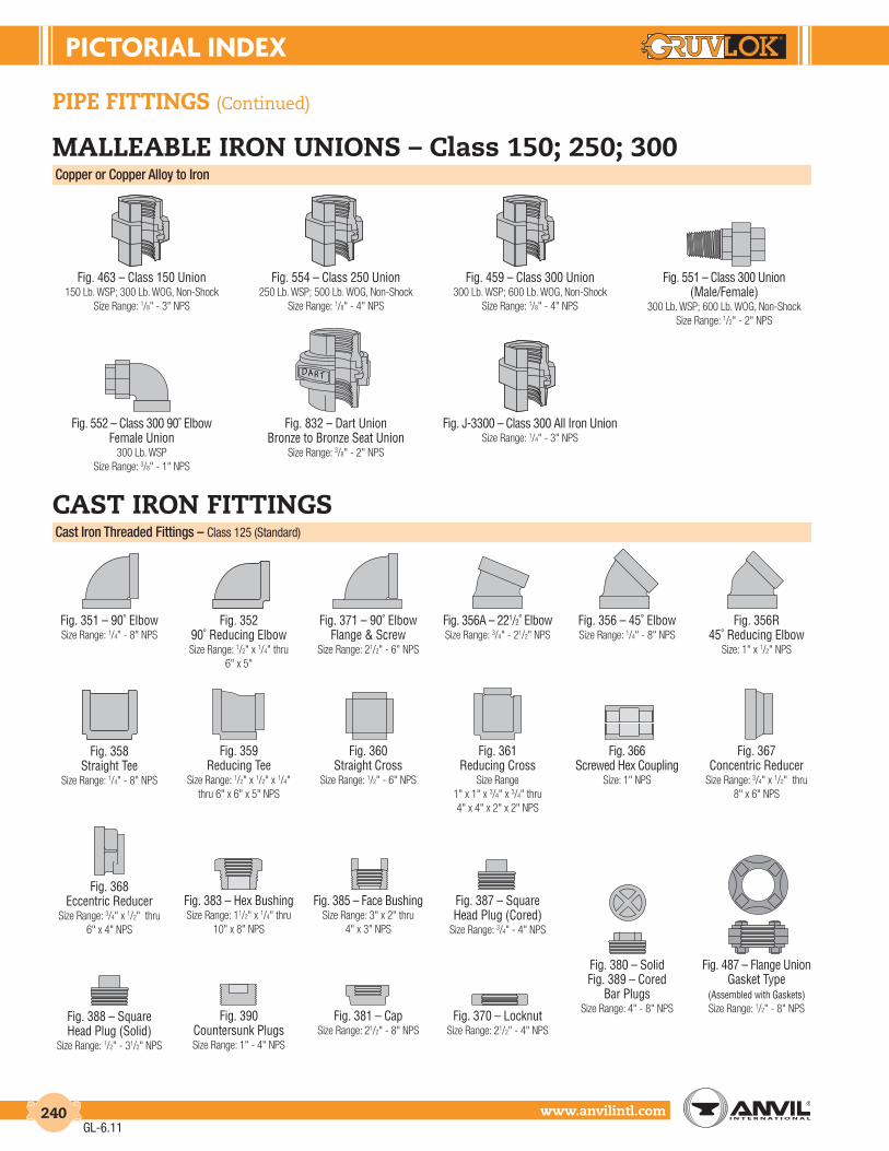
PIctorIAL IndEX
www.anvilintl.com240
pipe fittinGs (Continued)
malleable iron unions – class 150; 250; 300Copper or Copper Alloy to Iron
Fig. 463 – Class 150 Union150 Lb. WSP; 300 Lb. WOG, Non-Shock
Size Range: 1/8" - 3" NPS
Fig. 554 – Class 250 Union250 Lb. WSP; 500 Lb. WOG, Non-Shock
Size Range: 1/8" - 4" NPS
Fig. 459 – Class 300 Union300 Lb. WSP; 600 Lb. WOG, Non-Shock
Size Range: 1/8" - 4" NPS
Fig. 551 – Class 300 Union(Male/Female)
300 Lb. WSP; 600 Lb. WOG, Non-ShockSize Range: 1/2" - 2" NPS
Fig. 552 – Class 300 90˚ ElbowFemale Union
300 Lb. WSPSize Range: 3/8" - 1" NPS
Fig. 832 – Dart UnionBronze to Bronze Seat Union
Size Range: 3/8" - 2" NPS
Fig. J-3300 – Class 300 All Iron UnionSize Range: 1/4" - 3" NPS
AD R T
cast iron fittinGsCast Iron Threaded Fittings – Class 125 (Standard)
Fig. 351 – 90˚ ElbowSize Range: 1/4" - 8" NPS
Fig. 371 – 90˚ ElbowFlange & Screw
Size Range: 21/2" - 6" NPS
Fig. 356A – 221/2˚ ElbowSize Range: 3/4" - 21/2" NPS
Fig. 356 – 45˚ ElbowSize Range: 1/4" - 8" NPS
Fig. 35290˚ Reducing ElbowSize Range: 1/2" x 1/4" thru
6" x 5"
Fig. 358Straight Tee
Size Range: 1/4" - 8" NPS
Fig. 359Reducing Tee
Size Range: 1/2" x 1/2" x 1/4" thru 6" x 6" x 5" NPS
Fig. 360Straight Cross
Size Range: 1/2" - 6" NPS
Fig. 361Reducing Cross
Size Range1" x 1" x 3/4" x 3/4" thru4" x 4" x 2" x 2" NPS
Fig. 366Screwed Hex Coupling
Size: 1" NPS
Fig. 367Concentric Reducer
Size Range: 3/4" x 1/2" thru 8" x 6" NPS
Fig. 368Eccentric Reducer
Size Range: 3/4" x 1/2" thru 6" x 4" NPS
Fig. 383 – Hex BushingSize Range: 11/2" x 1/4" thru
10" x 8" NPS
Fig. 385 – Face BushingSize Range: 3" x 2" thru
4" x 3" NPS
Fig. 387 – Square Head Plug (Cored)
Size Range: 3/4" - 4" NPS
Fig. 388 – Square Head Plug (Solid)
Size Range: 1/2" - 31/2" NPS
Fig. 380 – SolidFig. 389 – Cored
Bar PlugsSize Range: 4" - 8" NPS
Fig. 390Countersunk PlugsSize Range: 1" - 4" NPS
Fig. 487 – Flange Union Gasket Type
(Assembled with Gaskets)Size Range: 1/2" - 8" NPS
Fig. 381 – CapSize Range: 21/2" - 8" NPS
Fig. 370 – LocknutSize Range: 21/2" - 4" NPS
Fig. 356R45˚ Reducing Elbow
Size: 1" x 1/2" NPS
GL-6.11

PIctorIAL IndEX
Intro
duct
ion
Coup
lings
Outle
tsFi
tting
sVa
lves
&
Acce
ssor
ies
High
Pres
sure
DI-L
OK®
Nipp
les
Plai
n-En
dFi
tting
sHD
PECo
uplin
gsSo
ck-It
®
Fitti
ngs
Stai
nles
sSt
eel M
etho
dRo
ll Gr
oove
rsIn
stal
latio
n&
Ass
embl
ySp
ecia
lCo
atin
gsDe
sign
Serv
ices
Tech
nica
lDa
taM
aste
r For
mat
3 Pa
rt Sp
ecs.
Pict
oria
lIn
dex
CTS
Copp
er
Syst
em
www.anvilintl.com 241
pipe fittinGs (Continued)
cast iron fittinGs (Continued)Cast Iron Threaded Fittings – Class 250 (Extra Heavy)
Fig. 421 – 90˚ ElbowSize Range: 1/4" - 3" NPS
Fig. 424 – 45˚ ElbowSize Range: 1/2" - 21/2" NPS
Fig. 425 – TeeSize Range: 1/4" - 4" NPS
Fig. 426 – Reducing TeeSize Range: 3/4" x 3/4" x 1/2" thru
2" x 2" x 11/2"
Cast Iron Drainage Fittings
Fig. 70190˚ Short Turn ElbowSize Range: 11/2" - 4" NPS
Fig. 701R – 90˚ Reducing Short Turn Elbow
Sizes: 11/2" x 11/4" & 2" x 11/2" NPS
Fig. 70290˚ Long Turn ElbowSize Range: 11/2" - 4" NPS
Fig. 702A90˚ Extra Long Turn Elbow
Sizes: 11/2" & 2" NPS
Fig. 70360˚ Short Turn Elbow
Size: 11/2" NPS
Fig. 70545˚ Short Turn ElbowSize Range: 11/2" - 4" NPS
Fig. 70645˚ Long Turn Elbow
Size: 11/2" NPS
Fig. 707 – 221/2˚ ElbowSizes: 11/2" & 2" NPS
Fig. 708 – 111/4˚ ElbowSizes: 11/2" & 2" NPS
Fig. 718 – 90˚ Street ElbowSizes: 11/2" & 2" NPS
Fig. 719 – 45˚ Street ElbowSizes: 11/2" & 2" NPS
Fig. 722 – TeeSizes: 11/2" & 2" NPS
Fig. 723 – Reducing TeeSize: 2" x 2" x 11/2" NPS
Fig. 726 – Sanitary Tee90˚ Short Turn
Size Range: 11/2" - 4" NPS
Fig. 727 – Sanitary Tee90˚ Reducing Short Turn
Sizes:2" x 2" x 11/2" & 2" x 11/2" x 11/2"
Fig. 729 – Sanitary Tee90˚ Reducing Double Short Turn
Size: 2" x 11/2" NPS
Fig. 730 – Y-Branch90˚ Long Turn
Sizes: 11/2" & 2" NPS
Fig. 731 – Y-Branch90˚ Reducing Long Turn
Size: 2" x 2" x 11/2" NPS
Fig. 734 – 45˚ Y-BranchSizes: 11/2" - 4" NPS
Fig. 735 – 45˚ Reducing Y-Branch
Sizes: 2" x 2" x 11/2" & 4" x 4" x 3"
Fig. 736 – 45˚ Double Y-Branch
Size: 11/2" NPS
Fig. 744 – Tucker ConnectionSize Range: 11/2" - 4" NPS
Fig. 753 – CouplingSize: 11/2" NPS
Fig. 752 – P-TrapSize Range: 11/2" - 3" NPS
Fig. 754 – Bath P-TrapSizes: 11/2" & 2" NPS
Cast Iron Threaded – Safety Valve Discharge Elbow
Fig. 1538 – Screwed Cast IronSize Range: 21/2" - 4" NPS
GL-7.12

PIctorIAL IndEX
www.anvilintl.com242
Cast Iron Flanged Fittings – Class 125 (Standard)
pipe fittinGs (Continued)
cast iron fittinGs (Continued)
Fig. 80190˚ Straight Elbow
Size Range: 11/2" - 12" NPS
Fig. 80245˚ Straight Elbow
Size Range: 11/2" - 12" NPS
Fig. 80390˚ Taper Reducing Elbow
Size Range:21/2" x 2" thru 12" x 10" NPS
Fig. 804 – StraightFig. 804R – ReducingLong Radius Elbow
Size Range:Fig. 804: 2" - 12" NPS
Fig. 804R: 4" x 3" thru 10" x 8"
Fig. 805 – Base ElbowSize Range: 3" - 12" NPS
Fig. 808 – Side Outlet ElbowSize Range: 4" - 8" NPS
Fig. 811 – Straight TeeSize Range: 11/2" - 12" NPS
Fig. 812 – Reducing TeeSize Range:
3" x 2" x 3" thru 12" x 12" x 10"
Fig. 821 – CrossSize Range: 2" - 10" NPS
Fig. 823 – LateralSize Range: 2" - 8" NPS
Fig. 825Concentric Reducer
Size Range: 2" x 11/2" thru 12" x 10" NPS
Iron Flanges – Class 125 (Standard)
Fig. 1018 – Cast Iron Blind Flange
Size Range:1" x 41/4" thru 12" x 19" NPS
Fig. 1010T – Cast Iron Flange Threaded
Size Range: 3" x 71/2" thru 12" x 19" NPS
Fig. 1016 – Reducing Companion Flange
Size Range:1" x 5" thru 8" x 19" NPS
Cast Iron Flanged Fittings – Class 250 (Extra Heavy)
Fig. 826Eccentric ReducerSize Range: 3" x 2" thru
12" x 10" NPS
Fig. 83190˚ Straight ElbowSize Range: 2" - 8" NPS
Fig. 841 – Straight TeeSize Range: 21/2" - 8" NPS
Fig. 842 – Reducing TeeSizes: 6" x 6" x 4" and
8" x 8" x 6" NPS
Fig. 855Concentric Reducer
Size Range:3" x 2" thru 10" x 8" NPS
Fig. 1011 – Cast IronCompanion Flange
Size Range:Fig: 1011: 3/4" x 37/8" thru
12" x 19" NPS
Fig. 1025 – Cast Iron Companion Flange
Size Range:11/4" x 51/4" thru 8" x 15" NPS
Fig. 1021 – Cast IronBlind Flange
Size Range:11/2" x 61/8" thru 8" x 15" NPS
Fig. 1030 – Cast Iron Companion Flange
Size Range:2" x 81/4" thru 4" x 11" NPS
Iron Flanges – Class 250 (Extra Heavy)
GL-6.11

PIctorIAL IndEX
Intro
duct
ion
Coup
lings
Outle
tsFi
tting
sVa
lves
&
Acce
ssor
ies
High
Pres
sure
DI-L
OK®
Nipp
les
Plai
n-En
dFi
tting
sHD
PECo
uplin
gsSo
ck-It
®
Fitti
ngs
Stai
nles
sSt
eel M
etho
dRo
ll Gr
oove
rsIn
stal
latio
n&
Ass
embl
ySp
ecia
lCo
atin
gsDe
sign
Serv
ices
Tech
nica
lDa
taM
aste
r For
mat
3 Pa
rt Sp
ecs.
Pict
oria
lIn
dex
CTS
Copp
er
Syst
em
www.anvilintl.com 243
pipe fittinGs (Continued)
pipe nipplesSeamless/Welded – Black & Galvanized
Seamless Pipe NipplesStd. Sch. 40, XH Sch. 80, Sch. 160, XXH
Size Range: 1/8" thru 6"
Fig. 336Standard, Full & HalfSize Range: 1/8" - 6" NPS
Fig. 337Extra Strong (XS), Full & Half
Size Range: 1/8" - 6" NPS
Fig. 348API Line Pipe CouplingSize Range: 1/8" - 12" NPS
Fig. 346Standard, Right & Left
Size Range: 1/2" - 2" NPS
Fig. 347Extra Strong (XS), Right & Left
Size Range: 1/2" - 2" NPS
Merchant Steel Bushings, Caps & Plugs
Solid Square Head PlugSize Range: 1/8" - 2" NPS
Hex BushingSize Range: 1/4" x 1/8" thru 1" x
3/4" NPS
Countersunk Plug (Square & Hex Socket)
Size Range: 1/8" - 2" NPS
Steel Hose FittingsFor fast, economical hose connections & repairsCombination Nipples
Combination NipplesNominal Pipe Sizes: 1/2" - 6"
Size Range: 1/2" - 2"
Hose MendersNominal Pipe Sizes: 1/2" - 6"
Size Range: 1/2" - 2"
Welded Pipe NipplesStd. Sch. 40, XH Sch. 80Size Range: 1/8" thru 6"
steel fittinGsSteel Pipe Couplings
Fig. 379Shallow Well CouplingSize Range: 11/4" - 2" NPS
Fig. 380Water Well Reamed and
Drifted CouplingSize Range: 11/4" - 2" NPS
Fig. 381#9 Drive Coupling
Size Range: 11/4" - 12" NPS
Flush BushingSize Range: 1/4" x 1/8" thru 1/2" x
3/8" NPS
CapSize Range: 1/8" - 3/4" NPS
GL-7.12

PIctorIAL IndEX
www.anvilintl.com244
pipe fittinGs (Continued)
forGed steel fittinGsClass 2000 Threaded
Fig. 2101 – 90˚ ElbowSize Range: 1/4" - 4" NPS
Fig. 2102 – 45˚ ElbowSize Range: 1/4" - 3" NPS
Fig. 2103 – TeeSize Range: 1/4" - 4" NPS
Fig. 2104 – CrossSize Range: 1/4" - 3" NPS
Class 3000 Threaded
Fig. 2111 – 90˚ ElbowSize Range: 1/8" - 4" NPS
Fig. 2112 – 45˚ ElbowSize Range: 1/8" - 4" NPS
Fig. 2114 – TeeSize Range: 1/8" - 4" NPS
Fig. 2115 – CrossSize Range: 1/8" - 4" NPS
Fig. 2113 – 90˚ Street ElbowSize Range: 1/8" - 2" NPS
Fig. 2116 – LateralSize Range: 1/2" - 2" NPS
Fig. 2117 – CouplingSize Range: 1/8" - 4" NPS
Fig. 2118 – Reducing CouplingSize Range: 1/4" x 1/8"- 4" x 11/2" NPS
Fig. 2119 – Half CouplingSize Range: 1/8" - 4" NPS
Fig. 2120 – Pipe CapSize Range: 1/8" - 4" NPS
Class 6000 Threaded
Fig. 2131 – 90˚ ElbowSize Range: 1/8" - 4" NPS
Fig. 2132 – 45˚ ElbowSize Range: 1/8" - 4" NPS
Fig. 2133 – 90˚ Street ElbowSize Range: 1/8" - 11/2" NPS
Fig. 2134 – TeeSize Range: 1/8" - 4" NPS
Fig. 2135 – CrossSize Range: 1/8" - 4" NPS
Fig. 2136 – LateralSize Range: 1/2" - 11/2" NPS
Fig. 2137 – CouplingSize Range: 1/8" - 4" NPS
Fig. 2138 – Reducing CouplingSize Range: 1/4" x 1/8"- 4" x 2" NPS
Fig. 2141 – Half CouplingSize Range: 1/8" - 4" NPS
Fig. 2143 – Pipe CapSize Range: 1/8" - 4" NPS
Class 3000 Socket-Weld
Fig. 2150 – 90˚ ElbowSize Range: 1/8" - 4" NPS
Fig. 2151 – 45˚ ElbowSize Range: 1/8" - 4" NPS
Fig. 2152 – TeeSize Range: 1/8" - 4" NPS
Fig. 2153 – CrossSize Range: 1/8" - 4" NPS
Fig. 2158 – LateralSize Range: 1/2" - 2" NPS
Fig. 2154 – CouplingsSize Range: 1/8" - 4" NPS
Fig. 2156 – Reducing CouplingSize Range: 1/4" x 1/8"- 4" x 2" NPS
Fig. 2155 – Half CouplingSize Range: 1/8" - 4" NPS
Fig. 2157 – Pipe CapSize Range: 1/8" - 4" NPS
GL-7.12

PIctorIAL IndEX
Intro
duct
ion
Coup
lings
Outle
tsFi
tting
sVa
lves
&
Acce
ssor
ies
High
Pres
sure
DI-L
OK®
Nipp
les
Plai
n-En
dFi
tting
sHD
PECo
uplin
gsSo
ck-It
®
Fitti
ngs
Stai
nles
sSt
eel M
etho
dRo
ll Gr
oove
rsIn
stal
latio
n&
Ass
embl
ySp
ecia
lCo
atin
gsDe
sign
Serv
ices
Tech
nica
lDa
taM
aste
r For
mat
3 Pa
rt Sp
ecs.
Pict
oria
lIn
dex
CTS
Copp
er
Syst
em
www.anvilintl.com 245
pipe fittinGs (Continued)
forGed steel fittinGs (Continued)Class 6000 Socket-Weld
Fig. 2170 – 90˚ ElbowSize Range: 1/2" - 4" NPS
Fig. 2171 – 45˚ ElbowSize Range: 1/2" - 4" NPS
Fig. 2172 – TeeSize Range: 1/2" - 4" NPS
Fig. 2173 – CrossSize Range: 1/2" - 2" NPS
Fig. 2178 – LateralSize Range: 1/2" - 11/2" NPS
Fig. 2174 – CouplingsSize Range: 1/2" - 4" NPS
Fig. 2176 – Reducing CouplingSize Range: 1/2" x 1/4"- 4" x 2" NPS
Fig. 2175 – Half CouplingsSize Range: 1/2" - 4" NPS
Fig. 2177 – Pipe CapsSize Range: 1/2" - 4" NPS
High Pressure Plugs & BushingsAnvil High Pressure Plugs and Bushings satisfy the requiement of ASME B16.11 Class 2000, 3000, and 6000.
Fig. 2122 – PlugsSquare Head
Size Range: 1/8" - 4" NPS
Fig. 2142 – PlugsHex Head
Size Range: 1/8" - 4" NPS
Fig. 2121 – PlugsRound Head
Size Range: 1/8" - 4" NPS
Fig. 2139 – BushingsHex Head
Size Range: 1/4" x 1/8"- 4" x 11/2" NPS
Fig. 2140 – BushingsFlush
Size Range: 1/4" x 1/8"- 2" x 1/4" NPS
Socket-Weld Reducer Inserts
Reducer inserts comply with MSS Standard SP-79. They enable standard socket-weld fittings to be used for making any combination of pipe line reductions quickly and economically. Socket-weld reducer inserts serve the same purpose as threaded reducing bushings with threaded fittings.
Fig. 2159 (Type 1) Fig. 2179 (Type 2)
CLASS 6000For use with Schedule 160 Pipe
Type 1 – Reducer Insert Type 2 – Reducer Insert Size Range: 3/8" x 1/4" thru 3" x 21/2" NPS Size Range: 3/8" x 1/4" thru 3" x 21/2" NPS
CLASS 3000For use with Schedule 40 & 80 Pipe
Type 1 – Reducer Insert Type 2 – Reducer Insert Size Range: 3/8" x 1/4" thru 3" x 1" NPS Size Range: 3/8" x 1/4" thru 3" x 1" NPS
Floor & Ceiling Plates
Fig. 1 – with SpringsFig. 2 – with Set Screw
Stamped Steel for Copper TubeSize Range: 1/4" - 6" NPS
Fig. 10 – with SpringsFig. 13 – with Set ScrewStamped Steel for Pipe
Size Range: 1/4" - 6" NPS
Fig. 20 – with Springs & exposed Rivet Hinge
Stamped Steel for PipeSize Range: 1/4" - 6" NPS
miscellaneousAll Purpose Asbestos Gaskets
Compressed Sheet Packing is a single-formula material suitable for a wide range of temperature-pressure combinations. It is used for sealing water,
steam, all oils, gases, alkalies, acids, refigerants & hydrocarbons.
Available in Eight Gauges: 1/100", 1/64", 1/32", 1/16", 3/32", 1/8", 3/16", & 1/4" (.2, .4, .8, 1.6, 3.1, 4.7 and 6.3 mm)
Full Face Ring
When ordering, specify bolt size & length required.Bolts are furnished in sizes:
1/4", 5/16", 3/8", 7/16", 1", 11/8", 11/4" (6.3, 7.9, 9.5, 11, 25, 29 and 32 mm) in varying lengths.
Length of bolts are measured from under head to extreme point.
GL-7.12

PIctorIAL IndEX
www.anvilintl.com246
BRANCHPIPE
RUNPIPE
BUTTWELD THREADED SOCKET WELD
pipe fittinGs (Continued)
anvil universal anviletsUniversal Buttweld AnviletsFull & Reducing Sizes Class 3000 & 6000
Schedule 160 & XXSSize Range: 1/2" - 4" NPS
Standard WeightXS/XH
For Oultet Sizes: 1/8" - 24" NPSSize Range: 1/8" - 24" NPS
BRANCHPIPE
BRANCHPIPE
Universal Socket-Weld Anvilets
Class 3000For Oultet Sizes: 1/8" - 4" NPS
Class 6000For Oultet Sizes: 1/2" - 2" NPS
Universal Threaded AnviletsFull & Reducing Sizes Class 3000 & 6000
Universal Flat Anvilets
Class 3000 Threaded, Buttweld & Socket-WeldSize Range: 1/4" - 3" NPS
Threaded Butt-Weld Socket-Weld
Class 3000For Oultet Sizes: 1/8" - 4" NPS
Class 6000For Oultet Sizes: 1/2" - 2" NPS
BRANCHPIPE
RUNPIPE
Universal Elbow AnviletsClass 3000 & 6000 Butt-Weld, Threaded, and Socket-Weld
Universal Lateral AnviletsClass 3000 & 6000 Buttweld and ThreadedLateral Anvilets provide a strong, readily attached 45˚ lateral outlet connection.
Class 3000Threaded & Socket-Weld/Standard & XS/XH Buttweld
Size Range: 1/2" - 2" NPS
BUTTWELD THREADED SOCKET WELD
Class 3000Standard/XS ButtweldSize Range: 1/2" - 2" NPS
merit® outlet fittinGsWeld-Miser™ Tee-Let®
Welding Outlet Fittings
Type A – Female ThreadSize Range: 1/2" - 4"
Type B – Male ThreadStandard WeightSize Range: 1" - 8"
Type C – Cut GrooveStandard WeightSize Range: 11/4" - 8"
Type C/R – Roll Groove Schedule 10Size Range: 11/4" - 6"
EliminatorAdjustable Drop NipplesSize Range: 1"x 1/2" thru 1"x 3/4"
Type M Type F
Hole TemplatesHand Held Hole TemplatesSize Range: 11/2" - 21/2"
Class 3000Threaded/StandardSize Range: 1/2" - 2" NPS
Class 6000Threaded & Socket-Weld
Size Range: 1/2" - 11/2" NPS
GL-7.12

PIctorIAL IndEX
Intro
duct
ion
Coup
lings
Outle
tsFi
tting
sVa
lves
&
Acce
ssor
ies
High
Pres
sure
DI-L
OK®
Nipp
les
Plai
n-En
dFi
tting
sHD
PECo
uplin
gsSo
ck-It
®
Fitti
ngs
Stai
nles
sSt
eel M
etho
dRo
ll Gr
oove
rsIn
stal
latio
n&
Ass
embl
ySp
ecia
lCo
atin
gsDe
sign
Serv
ices
Tech
nica
lDa
taM
aste
r For
mat
3 Pa
rt Sp
ecs.
Pict
oria
lIn
dex
CTS
Copp
er
Syst
em
www.anvilintl.com 247
pipe fittinGs (Continued)
Carbon Steel – Swage Nipples
Concentric Swage NipplesSize Range:
1/4" x 1/8" thru 1" x 3/4"11/4" x 1/4" thru 8" x 6"
Eccentric Swage NipplesSize Range: 1/4" x 1/8" thru 4" x 31/2"
Stainless Steel – Swage Nipples
Stainless & Alloy Steel Swage Nipples
Size Range: 1/4" x 1/8" thru 4" x 31/2"
Carbon Steel – Bull Plugs
Carbon Steel Bull PlugsSize Range: 1/8" - 8"
Solid Refinery PlugsBlack (Non-Plated)
Carbon SteelSize Range: 1/8" - 2"
Oil Country Fittings – Tubing Swages & Casing Swages
Large End UpsetReduced to Regular or UpsetSize Range: 1" x 3/4" thru 4" x 31/2"
Large End Non-UpsetReduced to Upset
Size Range: 1" x 3/4" thru 4" x 3"
Swage Nipples Oil CountryTubing & Casing Non EUE Ends
Size Range: 1" - 4"
Oil Country Fittings – Adapter Nipples
Bell NippleSize Range: 41/2" - 85/8"
Adapter NipplesSeamless Sch. 40Size Range: 3/4" - 12"
Tubing NipplesStandard WeightSize Range: 1" - 4"
Tubing NipplesExtra Heavy Weight
Size Range: 1" - 4"
Oil Country Fittings – Casing Nipples
Oil Country Casing NipplesSize Range: 41/2" - 16"
Oil Country Couplings – Casing Couplings
API Casing CouplingsShort Thread
Size Range: 41/2" - 20"
API Casing CouplingsLong Thread
Size Range: 41/2" - 133/8"
jb smith oil country
Combination Couplings J-55Size Range: 2" - 4"
Tubing Bull PlugsSize Range: 3/4" EUE - 3" EUE
Casing Bull PlugsSize Range: 41/2" - 103/4" API
Oil Country Fittings – Bull Plugs
API Bull Plug FemaleSize Range: 3/4" EUE - 4" EUE
Oil Country Couplings – Tubing Couplings
API Tubing CouplingsSize Range: 2" - 4"
Special ClearanceTubing CouplingsSize Range: 2" - 3"
Sub Tubing Couplings J-55Size Range: 2" EUE x 2" Reg thru
4" EUE x 4" RegChambers/Pressure Vessels
Size Range: 2" - 8"
Oil Country Fittings – Chamber Vessels
GL-7.12

PIctorIAL IndEX
www.anvilintl.com248
pipe fittinGs (Continued)
catawissa unionsWing Unions
Fig. 100Threaded Ends
1,000 psi cwp - 1,500 psi testSize Range: 2" - 8"
Fig. 100CThreaded Ends - Lug Union
1,000 psi cwp - 1,500 psi testSize: 2"
Fig. 200Buttweld Ends - Sch. 402,000 psi cwp - 3,000 psi test
Size Range: 1"- 6"
Fig. 200Threaded Ends
2,000 psi cwp - 3,000 psi testSize Range: 1" - 6"
Fig. 200CThreaded Ends - Lug Union
2,000 psi cwp - 3,000 psi testSize Range: 1" - 2"
Forged Steel UnionsManufactured to MSS Standard Practice SP83 (Class 6000 by method of MSS SP83).
CLASS 3000Fig. 2125 – Threaded
Fig. 2126 – Socket-WeldSize Range: 1/4" - 3" NPS
CLASS 6000Fig. 2127 – Threaded
Fig. 2128 – Socket-WeldSize Range: 1/4" - 2" NPS
THREADED SOCKET WELD
Fig. 206Threaded Ends
2,000 psi cwp - 3,000 psi testSize Range: 1" - 6"
Fig. 206Buttweld Ends - Sch. 402,000 psi cwp - 3,000 psi test
Size Range: 2" - 6"
Fig. 300Flat-Face Union
2,000 psi cwp - 3,000 psi testSize Range: 1" - 4"
Fig. 211Threaded Ends
Insulating Union2,000 psi cwp - 3,000 psi test
Sizes: 1" & 2"
Fig. 301Steam Service Union
3,000 psi cwp - 4,500 psi testSize Range: 1" - 3"
Fig. 400Threaded Ends
4,000 psi cwp - 6,000 psi testSize Range: 2" - 4"
Fig. 400Buttweld Ends - Sch. 804,000 psi cwp - 6,000 psi test
Size: 2"
Fig. 602Threaded Ends
6,000 psi cwp - 9,000 psi testSize Range: 1" thru 4"
Fig. 600Threaded Ends
6,000 psi cwp - 9,000 psi testSize Range: 1" thru 4"
Fig. 602Buttweld Ends - Sch. 806,000 psi cwp - 9,000 psi test
Size Range: 2" thru 4"
Fig. 607Threaded Ends
Well Service Union2,000 psi cwp - 3,000 psi test
Sizes: 11/2" & 2"
Fig. 1002Threaded Ends
10,000 psi cwp - 15,000 psi testSize Range: 1" - 4"
Fig. 1002Buttweld Ends - Sch. XXH10,000 psi cwp - 15,000 psi test
Size Range: 2" - 4"
Fig. 1002Buttweld Ends - Sch. 160
10,000 psi cwp - 15,000 psi testSize Range: 2" - 4"
Fig. 1502Threaded Ends
15,000 psi cwp - 22,500 psi testSizes: 2" & 3"
Fig. 1502Buttweld Ends - Sch. XXH15,000 psi cwp - 22,500 psi test
Sizes: 2" & 3"
Fig. 1502Buttweld Ends - Sch. 160
15,000 psi cwp - 22,500 psi testSizes: 2" & 3"
Fig. S1AHigh Speed Union
3,000 psi cwp - 4,500 psi testSize Range: 1" - 3"
Fig. 202Blanking Cap Only
with O-RingSize: 4"
Fig. 3L S1ATri-Lug High Speed Union3,000 psi cwp - 4,500 psi test
Size Range: 1" - 2"
GL-7.12

PIctorIAL IndEX
Intro
duct
ion
Coup
lings
Outle
tsFi
tting
sVa
lves
&
Acce
ssor
ies
High
Pres
sure
DI-L
OK®
Nipp
les
Plai
n-En
dFi
tting
sHD
PECo
uplin
gsSo
ck-It
®
Fitti
ngs
Stai
nles
sSt
eel M
etho
dRo
ll Gr
oove
rsIn
stal
latio
n&
Ass
embl
ySp
ecia
lCo
atin
gsDe
sign
Serv
ices
Tech
nica
lDa
taM
aste
r For
mat
3 Pa
rt Sp
ecs.
Pict
oria
lIn
dex
CTS
Copp
er
Syst
em
www.anvilintl.com 249
pipe hanGersCopper Tubing Hangers
Fig. CT-69Adjustable Swivel Ring
Size Range: 1/2" - 4"
Fig. CT-65Light Weight
Adjustable ClevisSize Range: 1/2" - 4"
Fig. CT-138RExtensions SplitTubing Clamp
Size Range: 1/2" - 2"
Fig. CT-121Copper TubingRiser Clamp
Size Range: 1/2" - 4"
Fig. CT-128RRod ThreadedCeiling Flange
Sizes: 3/8" thru 1/2"
Fig. CT-255Copper Tubing
Alignment GuideSize Range: 1" - 4"
Fig. 67Pipe or Conduit
HangerSize Range: 1/2" - 6"
Fig. 65Light Duty
Adjustable ClevisSize Range: 3/8" - 4"
Fig. 260Adjustable Clevis
HangerSize Range: 1/2" - 30"
Steel Pipe Clamps
Fig. 261Extension Pipe or
Riser ClampSize Range: 3/4" - 24"
Fig. 40Riser Clamp Standard
Size Range: 2" - 24"
Fig. 103Offset Pipe ClampSize Range: 3/4" - 8"
Fig. 100Extended Pipe Clamp
Size Range: 1/2" - 8"
Fig. 212Medium Pipe Clamp
Size Range: 1/2" - 30"
Fig. 212FPEarthquake
Bracing ClampSize Range: 21/2" - 12"
Fig. 216Heavy Pipe ClampSize Range: 3" - 42"
Fig. 295Double BoltPipe Clamp
Size Range: 3/4" - 36"
Fig. 295AAlloy Double Bolt
Pipe ClampSize Range: 11/2" - 24"
Fig. 295HHeavy Duty Double
Bolt Pipe ClampSize Range: 6" - 36"
Fig. 224Alloy Steel Pipe Clamp
Size Range: 4" - 16"
Fig. 246Heavy Duty Alloy Steel
Pipe ClampSize Range: 10" - 24"
Clevis
Fig. 167Insulation
Protection ShieldSize Range: 1/2" thru 24" pipe with up to 2" thick insulation.
Fig. 168Rib-Lok Shield
Size Range: 1/2" thru 8" pipe or copper tube with up to
2" thick insulation.
Fig. 160 to 166APipe Covering Protection Saddle
Size Range: 3/4" thru 36"
Pipe Shields & Saddles
Fig. 260 ISSClevis Hanger with Insulation Saddle
SystemSize Range: 2" - 16"
Fig. 300Adjustable Clevis for
Insulated LinesSize Range: 3/4" - 12"
Fig. 590Adjustable Clevis for Ductile or Cast Iron
Size Range: 3" - 24"
CPVC Pipe Hangers
Fig. 185One Hole Pipe Strap
Size Range: 3/4" - 2"
Fig. 186Two Hole Pipe Strap
Size Range: 3/4" - 2"
Fig. 188Two Hole Stand Off
StrapSize Range: 3/4" - 2"
Fig. 187Two Hole 90˚ Side
Mount StrapSize Range: 3/4" - 2"
Socket Clamps
Fig. 595 & Fig. 594Socket Clamp
For Ductile Iron orCast Iron Pipe
& Socket Clamp WasherSize Range: 4" - 24" pipe
Fig. 600 & Fig. 599Socket Clamp
For Ductile Iron orCast Iron Pipe
& Socket Clamp WasherSize Range: 3" - 24" pipe
Fig. 69FAdjustable Swivel Ring
Felt LinedSize Range: 1/2" - 6"
Fig. 67FCopper Tube Felt Lined
HangerSize Range: 1/2" - 6"
GL-7.12

PIctorIAL IndEX
www.anvilintl.com250
pipe hanGers (Continued)
Beam Clamps
Fig. 86 & 88C-Clamp with Set
Screw and Lock NutSize Range: 3/8" - 3/4"
Fig. 95C-Clamp with Lock Nut
Sizes: 3/8" and 1/2"
Fig. 89Retaining Clip
Size Range: 3/8" - 1/2"
Fig. 89XRetaining Clip
Size Range: 3/8" - 3/4"
Fig. 92Universal C-Type Clamp
Standard ThroatSizes: 3/8" and 1/2"
Fig. 93Universal C-Type Clamp
Wide ThroatSizes: 3/8" and 1/2"
Fig. 94Wide Throat Top Beam
C-ClampSizes: 5/8" and 3/4"
Fig. 227Top Beam Clamp
Fig. 217Adjustable SideBeam Clamp
Size Range: 3" - 75/8"
Fig. 14Adjustable SideBeam ClampSizes: 3/8" - 5/8"
Fig. 218Malleable Beam Clamp without Extension Piece
Fig. 228Universal Forged Steel
Beam Clamp
Fig. 292 & 292LBeam Clamp with Weldless Eye Nut
Ceiling Plates & Flanges
Fig. 395Cast Iron
Ceiling PlateSize Range: 1/2" - 8"
Fig. 127Plastic
Ceiling PlateSizes: 3/8" and 1/2"
Fig. 128RRod Threaded,Ceiling FlangeSizes: 3/8" & 1/2"
Fig. 153Pipe Hanger
FlangeSize Range: 3/8" - 3/4"
Structural Attachments
Fig. 55 & Fig. 55LStructural
Welding LugSize Range:
Fig. 55: 1/2" - 33/4"Fig. 55L: 1/2" - 2"
Fig. 54Two Hole Welding
Beam LugSize Range: 1/2" - 21/4"
Fig. 60Steel Washer PlateSize Range: 3/8" - 33/4"
Fig. 66Welded Beam Attachment
Size Range: 3/8" - 31/2"
Fig. 112 & 113Brace Fitting Compete
Sizes: 1" and 11/4"
Brackets
Fig. 202Iron Side Beam
BracketSize Range: 3/8" - 5/8"
Fig. 206Steel Side Beam
BracketSize Range: 3/8" - 5/8"
Fig. 207Threaded Steel
Side Beam BracketSizes: 3/8" and 1/2"
Fig. 194Light WeldedSteel Bracket
Fig. 195Medium Welded
Steel Bracket
Fig. 199Heavy WeldedSteel Bracket
Fig. 133Standard Duty Beam
ClampSize Range: 4" - 12"
Fig. 134Heavy Duty Beam
ClampSize Range: 4" - 12"
Fig. 46Universal Trapeze
Assembly
Fig. 45Channel Assembly
Fig. 50Equal Leg Angle for Trapeze Assembly
Trapeze
U-Bolts
Fig. 137 & 137SStandard U-Bolt
Size Range: 1/2" - 36"
Fig. 137CPlastic Coated
U-BoltSize Range: 1/2" - 8"
Fig. 120Light Weight
U-BoltSize Range: 1/2" - 10"
Fig. 189Staight Eye Socket
Size: 3/8"
Fig. 190Off-Set Eye Socket
Size: 3/8"
GL-7.12

PIctorIAL IndEX
Intro
duct
ion
Coup
lings
Outle
tsFi
tting
sVa
lves
&
Acce
ssor
ies
High
Pres
sure
DI-L
OK®
Nipp
les
Plai
n-En
dFi
tting
sHD
PECo
uplin
gsSo
ck-It
®
Fitti
ngs
Stai
nles
sSt
eel M
etho
dRo
ll Gr
oove
rsIn
stal
latio
n&
Ass
embl
ySp
ecia
lCo
atin
gsDe
sign
Serv
ices
Tech
nica
lDa
taM
aste
r For
mat
3 Pa
rt Sp
ecs.
Pict
oria
lIn
dex
CTS
Copp
er
Syst
em
www.anvilintl.com 251
pipe hanGers (Continued)
Concrete Inserts & Attachments
Fig. 152Screw Concrete Insert
Size Range: 3/8" - 7/8"
Fig. 282Universal
Concrete InsertSize Range: 3/8" - 7/8"
Fig. 281Wedge Type
Concrete InsertSize Range: 1/4" - 7/8"
Fig. 286Iron Cross DesignSize Range: 3/4" - 11/2"
Fig. 284Metal Deck HangerSize Range: 3/8" - 3/4"
Fig. 285Light Weight Concrete
InsertSize Range: 1/4" - 5/8"
Fig. 52Concrete Rod
Attachment PlateSize Range: 3/8" - 11/4"
Fig. 47Concrete Single Lug
PlateSize Range: 1/2" - 2"
Fig. 49Concrete Clevis Plate
Size Range: 3/8" - 13/4"
Hanger Rods & Accessories
Fig. 142Coach Screw Rods
Machine Threaded on Opposite End
Sizes: 3/8" and 1/2"
Fig. 146Continuous Thread
Sizes: 1/4" - 11/2"Stocked in six, ten & twelve foot lengths. Other even foot lengths
can be furnished to order.
Fig. 140 & 253Machine Threaded Rods Threaded Both Ends
Sizes: 3/8" - 5"
Fig. 248 & 248LEye Rod Not Welded
Size Range: 3/8" - 21/2"
Fig. 278 & 278LEye Rod Welded
Size Range: 3/8" - 21/2"
Fig. 248XLinked Eye Rods
Size Range: 3/8" - 21/2"
Fig. 278XLinked Eye Rods
WeldedSize Range: 3/8" - 21/2"
Fig. 148Rod with Eye EndSize Range: 23/4" - 5"
Fig. 135, 135E & 135RRod Coupling
Size Range:Fig. 135: 3/8" - 1"Fig. 135E: 1/4" - 1"
Fig. 135R: 3/8" x 1/4" - 7/8" x 3/4"
Fig. 136 & 136RStraight Rod Coupling
Size Range: 1/4" - 1"
Fig. 114Turnbuckle Adjuster
Size Range: 1/4" - 3/4"
Fig. 110RSocket, Rod Threaded
Size Range: 1/4" - 7/8"
Fig. 157Extension PieceSize Range: 3/8" - 7/8"
Fig. 299Forged Steel Clevis
Size Range: 3/8" - 4"
Fig. 233Turnbuckle
Size Range: 11/4" - 5"
Fig. 230Turnbuckle
Size Range: 3/8" - 21/2"
Fig. 290 & 290LWeldless Eye NutSize Range: 3/8" - 21/2"
Fig. 291Clevis Pin with Cotters
Size Range: 1/2" - 4"
Pipe Rings
Fig. 108Split Pipe Ring
Size Range: 3/8" - 8"
Fig. 138RExtension Split Pipe Clamp
Size Range: 3/8" - 3"
Fig. 104Adjustable Swivel Ring, Split Ring Type
Size Range: 3/8" - 8"
Fig. 69Adjustable Swivel Ring
Size Range: 1/2" - 8"
Pipe Supports
Fig. 62Type A, B & CPipe Stanchion
Size Range: 2" - 18"
Fig. 63Type A, B & CPipe Stanchion
Size Range: 21/2" - 42"
Fig. 192Adjustable PipeSaddle Support
Size Range: 2" - 12"
Fig. 191Adjustable Pipe
Saddle with U-BoltSize Range: 2" - 12"
Fig. 264Adjustable PipeSaddle Support
Size Range: 21/2" - 36"
Fig. 265Adjustable PipeSaddle Support
Size Range: 4" - 36"
Fig. 258Stanchion PipeSaddle Support
Size Range: 4" - 36"
Fig. 259Adjustable PipeSaddle Support
Size Range: 4" - 36"
Fig. 136:
Fig. 136R:
GL-7.12

PIctorIAL IndEX
www.anvilintl.com252
pipe hanGers (Continued)
Spring Hangers
Fig. 82 & C-82Short Spring
Fig. B-268 & C-268Standard Spring
Fig. 98 & C-98Double Spring
Pipe Rolls
Fig. 177Adjustable Pipe
Roll SupportSize Range: 1" - 30"
Fig. 171Single Pipe RollSize Range: 1" - 30"
Fig. 178Spring Cushion Hanger
Fig. 181Adjustable Steel Yoke
Pipe RollSize Range: 21/2" - 24"
Fig. 175Roller Chair
Size Range: 2" - 30" pipe
Fig. 277Pipe Roll & Base Plate
Size Range: 2" - 24"
Fig. 271Pipe Roll StandSize Range: 2" - 42"
Fig. 274, 274P & 275Adjustable Pipe
Roll StandSize Range: 2" - 42"
Pipe Guides & Slides
Fig. 255Pipe Alignment GuideSize Range: 1" - 24" and Insulation Thickness of 1" thru 4" (Also available in
copper tube sizes)
Fig. 256Pipe Alignment GuideSize Range: 1" - 24" Pipe and Insulation Thickness of
1" thru 4"
Fig. 257 & 257AStructural Tee
Slide AssemblySize Range: All Sizes within
Maximum Load Rating
Fig. 436 & 436AFabricated TeeSlide Assembly
Size Range: All Sizes within Maximum Load Rating
Fig. 439 & 439AStructural "H"
Slide AssemblySize Range: 6" - 36"
Fig. 432Special Clamp
Size Range: 2" - 24"
Fig. 212Medium Pipe Clamp
Size Range: 2" - 30"
Constant Supports
Model R 80-VVertical Constant
Support
Model R 81-HHorizontal Constant
Support
Size Range: Anvil Model R constant support hangers are made in two basic designs, 80-V & 81-H constant supports are made
in nine different frame sizes & 110 spring sizes to accomodate travels from 11/2" to 20" & loads from 27 lbs to 87,500 lbs.
Horizontal Traveler & Sway Brace
Fig. 170Horizontal Traveler
Size Range: Available in Four Sizes to Take Loads to 20,700
(LBS). All sizes provide for 12" of Horizontal Travel.
Fig. 296, 297, 298, 301, 302 & 303
Sway BraceSize Range: Pre Loads from
50 to 1,800 Pounds & maximum forces from 200
to 7,200 Pounds.
Sway Strut Assembly
Fig. 211, C-211,640, C-640
Sway Strut Assembly
Fig. 222 & C-222Mini-Sway Strut
Assembly
Snubbers
Fig. 3306 & 3307Hydraulic Shock & Sway Suppressor (Snubber)
Size Range: Six Standard Sizes with Load Ratings from 350 to 50,000 (LBS).
Fig. 312Tapered Pin
Size Range: 3/8" - 21/2"
Fig. 200 & C-200 / Fig. 201 & C-201Hydraulic Shock & Sway Suppresor
(Snubber)Size Range: Nine standard sizes with load ratings from 350 (LBS) to 120,000 (LBS).
Straps
Fig. 126One-Hole ClampSize Range: 3/8" - 4"
Fig. 262Strap Short
Size Range: 1/2" - 4"
Fig. 243Pipe Strap
Size Range: 1/2" - 6" pipe
Fig. 244Pipe Strap
Size Range: 1/2" - 6" pipe
Triple Spring,Triple Spring-CR
Quadruple Spring,Quadruple Spring-CR
GL-7.12

PIctorIAL IndEX
Intro
duct
ion
Coup
lings
Outle
tsFi
tting
sVa
lves
&
Acce
ssor
ies
High
Pres
sure
DI-L
OK®
Nipp
les
Plai
n-En
dFi
tting
sHD
PECo
uplin
gsSo
ck-It
®
Fitti
ngs
Stai
nles
sSt
eel M
etho
dRo
ll Gr
oove
rsIn
stal
latio
n&
Ass
embl
ySp
ecia
lCo
atin
gsDe
sign
Serv
ices
Tech
nica
lDa
taM
aste
r For
mat
3 Pa
rt Sp
ecs.
Pict
oria
lIn
dex
CTS
Copp
er
Syst
em
www.anvilintl.com 253
PIPE HANGERS • SWAY BRACE - SEISMIC
Pipe Brace Clamps Structural Attachments
Fig. 770Q Brace ClampSize Range: 1" - 6"
Service Pipe
Fig. 776Brace Clamp
Size Range: 21/2" - 8" Service Pipe
Fig. 775Lateral/Longitudinal
Brace ClampSize Range: 21/2" - 8"
Service Pipe
Fig. 778Bar Joist and Beam Attachment (WF)Size Range: Flange
Thickness 1/8" thru 3/4"
Fig. 772Adjustable Steel Beam
AttachmentSize Range: Flange Widths
4" thru 15"
Fig. 779Multi-Connector
AdapterSize Range: 1" - 8"
Service Pipe
Restraints
Fig. 773Surge RestrainerSize Range: 3/4" - 2"Swivel Ring Hanger
Fig. 777Swivel Joint
Connector Rod TapSize Range: 3/8" Rod
Diameter
Sway Brace Attachment
Fig. 771Sway Brace Swivel AttachmentSize Range: 1" and 11/4" Brace Pipe
GL-7.12

PIctorIAL IndEX
www.anvilintl.com254
Channels
as 100Channel
Size: 15/8" x 31/4" x 12 GA.
as 100ehChannel with
Elongated HolesSize: 15/8" x 31/4" x 12 GA.
9/16" x 11/8" Elongated Holes on 2" Centers.
as 100koChannel withKnock Outs
Size: 15/8" x 31/4" x 12 GA.7/8" Knock Outs on 6" Centers.
as 100hChannel with Holes
Size: 15/8" x 31/4" x 12 GA.9/16" Holes on 17/8" Centers.
as 100sChannel with Long SlotsSize: 15/8" x 31/4" x 12 GA.
13/32" x 3" Slots on 4" Centers
as 100btbWelded Channel
Size: 15/8" x 61/2" x 12 GA.Two Pcs. AS 100 Welded
Back-to-Back.
as 150Channel
Size: 15/8" x 27/16" x 12 GA.
as 150ehChannel with
Elongated HolesSize: 15/8" x 27/16" x 12 GA. 9/16" x 11/8" Elongated Holes
on 2" Centers.
as 150koChannel withKnock Outs
Size: 15/8" x 27/16" x 12 GA. 7/8" Knock Outs on 6" Centers.
as 150hChannel with Holes
Size: 15/8" x 27/16" x 12 GA. 9/16" Holes on 17/8" Centers.
as 150sChannel with Long SlotsSize: 15/8" x 27/16" x 12 GA.
13/32" x 3" Slots on 4" Centers.
as 150btbWelded Channel
Size: 15/8" x 47/8" x 12 GA.Two Pcs. AS 150 Welded
Back-to-Back.
as 210Channel
Size: 15/8" x 15/8" x 14 GA.
as 210ehChannel with
Elongated HolesSize: 15/8" x 15/8" x 14 GA.
9/16" x 11/8" Elongated Holes on 2" Centers.
as 210koChannel withKnock Outs
Size: 15/8" x 15/8" x 14 GA. 7/8" Knock Outs on 6" Centers.
as 210hChannel with Holes
Size: 15/8" x 15/8" x 14 GA. 9/16" Holes on 17/8" Centers.
as 210sChannel with Long SlotsSize: 15/8" x 15/8" x 14 GA.
13/32" x 3" Slots on 4" Centers.
as 210btbWelded Channel
Size: 15/8" x 31/4" x 14 GA.Two Pcs. AS 210 Welded
Back-to-Back.
as 200btbWelded Channel
Size: 15/8" x 31/4" x 12 GA.Two Pcs. AS 200 Welded
Back-to-Back.
as 200stsWelded Channel
Size: 15/8" x 31/4" x 12 GA.Two Pcs. AS 200 Welded
Back-to-Back.
as 200btsWelded Channel
Size: 15/8" x 31/4" x 12 GA.Two Pcs. AS 200 Welded
Side-to-Back.
as 200stsrWelded Channel
Size: 15/8" x 31/4" x 12 GA.Two Pcs. AS 200 Welded Side-to-Opposite Side.
as 200Channel
Size: 15/8" x 15/8" x 12 GA.
as 200ehChannel with
Elongated HolesSize: 15/8" x 15/8" x 12 GA.
9/16" x 11/8" Elongated Holes on 2" Centers.
as 200koChannel withKnock Outs
Size: 15/8" x 15/8" x 12 GA. 7/8" Knock Outs on 6" Centers.
as 200hChannel with Holes
Size: 15/8" x 15/8" x 12 GA. 9/16" Holes on 17/8" Centers.
as 200sChannel with Long SlotsSize: 15/8" x 15/8" x 12 GA.
13/32" x 3" Slots on 4" Centers.
as 200h3Channel with Holeson all Three Sides
Size: 15/8" x 15/8" x 12 GA. 9/16" Holes on all three sides
are on 17/8" Centers.
as 300Channel
Size: 15/8" x 13/8" x 12 GA.
as 300ehChannel with
Elongated HolesSize: 15/8" x 13/8" x 12 GA.
9/16" x 11/8" Elongated Holes on 2" Centers.
as 300koChannel withKnock Outs
Size: 15/8" x 13/8" x 12 GA. 7/8" Knock Outs on 6" Centers.
as 300hChannel with Holes
Size: 15/8" x 13/8" x 12 GA. 9/16" Holes on 17/8" Centers.
as 300sChannel with Long SlotsSize: 15/8" x 13/8" x 12 GA.
13/32" x 3" Slots on 4" Centers.
as 300btbWelded Channel
Size: 15/8" x 23/4" x 12 GA.Two Pcs. AS 300 Welded
Back-to-Back.
as 200eh btbWelded Channel
Size: 15/8" x 31/4" x 12 GA.Two Pcs. AS 200EH Welded
Back-to-Back.9/16" x 11/8" Elongated Holes
on 2" Centers.
GL-6.11

PIctorIAL IndEX
Intro
duct
ion
Coup
lings
Outle
tsFi
tting
sVa
lves
&
Acce
ssor
ies
High
Pres
sure
DI-L
OK®
Nipp
les
Plai
n-En
dFi
tting
sHD
PECo
uplin
gsSo
ck-It
®
Fitti
ngs
Stai
nles
sSt
eel M
etho
dRo
ll Gr
oove
rsIn
stal
latio
n&
Ass
embl
ySp
ecia
lCo
atin
gsDe
sign
Serv
ices
Tech
nica
lDa
taM
aste
r For
mat
3 Pa
rt Sp
ecs.
Pict
oria
lIn
dex
CTS
Copp
er
Syst
em
www.anvilintl.com 255
anvil-strut™ (Continued)
Channels (continued)
Channel NutsChannel Hardware
as 400Channel
Size: 15/8" x 1" x 12 GA.
as 400ehChannel with
Elongated HolesSize: 15/8" x 1" x 12 GA.
9/16" x 11/8" Elongated Holes on 2" Centers.
as 400koChannel withKnock Outs
Size: 15/8" x 1" x 12 GA.7/8" Knock Outs on 6" Centers.
as 400hChannel with Holes
Size: 15/8" x 1" x 12 GA.9/16" Holes on 17/8" Centers.
as 400sChannel with Long Slots
Size: 15/8" x 1" x 12 GA. 13/32" x 3" Slots on 4" Centers.
as 400btbWelded Channel
Size: 15/8" x 2" x 12 GA.Two Pcs. AS 400 Welded
Back-to-Back.
as 500Channel
Size: 15/8" x 13/16" x 14 GA.
as 500ehChannel with
Elongated HolesSize: 15/8" x 13/16" x 14 GA.
9/16" x 11/8" Elongated Holes on 2" Centers.
as 500hChannel with Holes
Size: 15/8" x 13/16" x 14 GA. 9/16" Holes on 17/8" Centers.
as 500sChannel with Long SlotsSize: 15/8" x 13/16" x 14 GA.
13/32" x 3" Slots on 4" Centers.
as 500btbWelded Channel
Size: 15/8" x 15/8" x 14 GA.Two Pcs. AS 500 Welded
Back-to-Back.
as 520Channel
Size: 15/8" x 13/16" x 12 GA.
as 520ehChannel with
Elongated HolesSize: 15/8" x 13/16" x 12 GA.
9/16" x 11/8" Elongated Holes on 2" Centers.
as 520hChannel with Holes
Size: 15/8" x 13/16" x 12 GA. 9/16" Holes on 17/8" Centers.
as 520sChannel with Long SlotsSize: 15/8" x 13/16" x 12 GA.
13/32" x 3" Slots on 4" Centers.
as 520btbWelded Channel
Size: 15/8" x 15/8" x 12 GA.Two Pcs. AS 520 Welded
Back-to-Back.
as 560Channel
Size: 15/8" x 13/16" x 16 GA.
as 560ehChannel with
Elongated HolesSize: 15/8" x 13/16" x 16 GA.
9/16" x 11/8" Elongated Holes on 2" Centers.
as 707Metal RacewayClosure Strip
For All 15/8" Width Channels.(10' Length)
as 707pMetal PaintedClosure Strip
For All 15/8" Width Channels.(10' Length)
as ls - Clamping Nut with Long Spring
Use with AS 100 & AS 150
as ns - Clamping Nut without Spring
Use with all 15/8" wide channel
as ss - Clamping Nut with Short Spring
Use with AS 400 and AS 500
as rs - Clamping Nut with Regular Spring
Use with AS 200, AS 210 and AS 300
as tG - Top Grip Nut with Spring on Top
Use with all 15/8" wide channel
as 517Stud Nut with RS Spring
as 3281Double Conveyer
Adjusting NutUse with all 15/8" wide channel
as 83Hexagon Nut
fig. 135Rod Coupling
fig. 146Continuous Threaded Rod
as 203Linked Eyelet with Stud
as 209Flat Washer
as 211Lock Washer
as 230Fender Washer
as 6075Slotted Hex HeadMachine Screw
as 6108Square Nut as 3500
Seismic Rod Stiffener
as 6024Hex Head Cap Screw
GL-6.11

PIctorIAL IndEX
www.anvilintl.com256
anvil-strut™ (Continued)
Clamps & Accessories
as 85Rod or Insulator Support
fig. 86Clamp with Lock Nut
fig. 93Top Beam "C" ClampSize Range: 3/8" - 1/2"
fig. 94Top Beam "C" ClampSize Range: 5/8" - 3/4"
fig. 95Clamp with Lock Nut
as 135xLight Duty Beam Clamp
as 684Beam Clamp
as 685Beam Clamp
as 686Beam Clamp
as 855Angular "C" Beam ClampAS 855 1 - Use with AS 200
and AS 210.AS 855 2 - Use with AS 500.
as 858Heavy Duty Suspension
Rod Beam ClampSafety Anchor Strap AS 871
sold separately.
as 865Wide Throat Heavy Duty
Beam ClampSafety Anchor Strap AS 871
sold separately.
as 871Safety Anchor Strap
(For Heavy Duty Beam Clamps)
as 907"I" Beam Clamp
Includes Cup Point Set Screw.
as 998"I" Beam ClampIncludes Set Screw.
as 2623Swivel Adapter
Use with AS 2622 Beam Clamp.
as 2651Beam Clamp
as 2656"U" Bolt Beam Clamp
with Hook
as 2657Double "U" Bolt
Beam Clamp
Splice Clevis
Plates
as 631Two Hole Splice Clevis
Use with AS 200 & AS 210.
as 644Two Hole Splice Clevis
Use with AS 500 & AS 520.
as 629Three Hole Splice ClevisUse with AS 200 & AS 210.
as 645Three Hole Splice ClevisUse with AS 500 & AS 520.
as 616Four Hole Splice ClevisUse with AS 200 & AS 210.
as 646Four Hole Splice Clevis
Use with AS 500.
as 602Three Hole Splice Plate
as 617Three Hole Swivel Plate
as 620Two Hole Connecting Plate
as 712Cross Plate
as 714"T" Plate
as 715"T" Plate - 90˚
as 718Flat Angle Plate
as 719Four Hole Corner Plate
as 888Four Hole Splice Plate
as 619Square Washer
as 2504Square Washer with
Channel Guide
as 601Two Hole Splice Plate
GL-6.11

PIctorIAL IndEX
Intro
duct
ion
Coup
lings
Outle
tsFi
tting
sVa
lves
&
Acce
ssor
ies
High
Pres
sure
DI-L
OK®
Nipp
les
Plai
n-En
dFi
tting
sHD
PECo
uplin
gsSo
ck-It
®
Fitti
ngs
Stai
nles
sSt
eel M
etho
dRo
ll Gr
oove
rsIn
stal
latio
n&
Ass
embl
ySp
ecia
lCo
atin
gsDe
sign
Serv
ices
Tech
nica
lDa
taM
aste
r For
mat
3 Pa
rt Sp
ecs.
Pict
oria
lIn
dex
CTS
Copp
er
Syst
em
www.anvilintl.com 257
anvil-strut™ (Continued)
"U" Supports
"Z" Supports
Angle Fittings and Connectors
as 613"U" Support
Use with AS 200, AS 210 and AS 500BTB.
as 679"U" Support
Use with AS 100, AS 200BTB and AS 210BTB.
as 710"U" Support
Use with AS 300.
as 929"U" Support
Use with AS 500 & AS 520.
as 978"U" Support
Use with AS 400.
as 2119"U" Connector
as 2648"U" Support
Use with AS 150.
as 687Slotted "U" Support
Use with AS 200 & AS 210.
as 721"U" Support
Use with AS 100, AS 200BTB and AS 210BTB.
as 678Three Hole "U" Support
Use with AS 150BTB.
as 733Six Hole "U" Support
Use with AS 200 & AS 210.
as 735Eight Hole "U" Support
Use with AS 200BTB.
as 609Two Hole Offset
"Z" Support
as 611"Z" Support
Use with AS 200, AS 210 and AS 500BTB.
as 612"Z" Support
Use with AS 400.
as 711"Z" Support
Use with AS 300.
as 928"Z" Support
Use with AS 500 &AS 520.
as 2601"Z" Support
Use with AS 150.
as 603Two Hole End Angle
as 604Two Hole Corner Angle
as 624Two Hole Closed Angle
Connector
as 633Two Hole Open Angle
Connector
as 763, as 764Slotted Adjustment
Corner Angle
as 806Two Hole Angle with
Impressions on Both Legs
as 921One Hole Angle
as 2144Corner Angle
as 2520Two Hole Adjustment Angle
as 2545Slotted 90˚ Angle
as 605Three Hole Corner Angle
as 606Three Hole Corner Angle
as 745Three Hole Corner Angle
as 3049Two Hole Slotted 90˚
Corner Connector
as 607Four Hole Corner Angle
as 781Four Hole Open Angle
Connector
as 793Four Hole Closed Angle
Connectoras 614
Four Hole Joint Corner Connector
as 615Four Hole Shelf Joint
Angle Connector
as 689Adjustable Double
Slotted Corner Connector
as 748Four Hole Corner Joint
Connector
as 927Five Hole Corner Connector
as 744Flat Corner Connector
as 750Four Hole Corner Connector
as 756"Z" Support
Use with AS 100, AS 200BTB & AS 210BTB.
GL-7.12

PIctorIAL IndEX
www.anvilintl.com258
anvil-strut™ (Continued)
as 2190Flat Corner Connector
as 747Symmetrical Four Hole
Connector
as 854Flat Connector
as 925Symmetrical Three Hole
Joint Connector
as 2112Cross Connector
as 665Four Hole Double Corner
Connector
as 720RH & LH Angle Plate
Connector
as 922 rh & lhTwo Hole Single Corner
Angle Connector
as 923Five Hole Two Angle
Connector
as 2128 rh & lhSix Hole Corner Connector
as 666Six Hole Double Corner
Connector
as 821Eight Hole Double Angle
Connector
Angle Fittings and Connectors (continued)
as 667Eight Hole Double Corner Connector
as 913Ten Hole Two Angle
Clevis Connector
as 668Six Hole Three
Angle Connector
as 669Twelve Hole Three Angle
Clevis Connector
as 2560 & as 2561Conduit Connector Fitting
Assembly
as 3060Offset Connector
as 9402Two Hole
Hinge Connector
as 9403Three Hole
Hinge Connector
as 9404Four Hole
Hinge Connector
as 677Cup Support for
Standard Single StrutUse with AS 200 and AS 210.
as 993Inside Clevis
as 2401 thru as 2403Ladder Rung
as 2064Double Column
Post BaseUse with AS 100, AS 200BTB, AS 200STS, AS 200BTS and
AS 200STR Channel
as 3013Single Column
Post BaseUse with AS 200 and
AS 210 Channel.
as 3025Post Base
Use with AS 200 andAS 210 Channel.
as 3029Double Column
Post BaseUse with all 31/4" Channels.
as 3033Post Base
Use with AS 200 andAS 210 Channel.
as 3040Post Base
Use with AS 200 andAS 210 Channel.
as 3064Double Column Post BaseUse with all 31/4" Channels.
as 9400Adjustable Base
as 3064 sQDouble Column Post BaseUse with all 31/4" Channels.
Post Bases
as 3013 sQSingle Column
Post BaseUse with AS 200 and
AS 210 Channel.
as 3013 flSingle Column
Post BaseUse with AS 200 and
AS 210 Channel.
as 3025 flPost Base
Use with AS 200 andAS 210 Channel.
GL-7.12

PIctorIAL IndEX
Intro
duct
ion
Coup
lings
Outle
tsFi
tting
sVa
lves
&
Acce
ssor
ies
High
Pres
sure
DI-L
OK®
Nipp
les
Plai
n-En
dFi
tting
sHD
PECo
uplin
gsSo
ck-It
®
Fitti
ngs
Stai
nles
sSt
eel M
etho
dRo
ll Gr
oove
rsIn
stal
latio
n&
Ass
embl
ySp
ecia
lCo
atin
gsDe
sign
Serv
ices
Tech
nica
lDa
taM
aste
r For
mat
3 Pa
rt Sp
ecs.
Pict
oria
lIn
dex
CTS
Copp
er
Syst
em
www.anvilintl.com 259
anvil-strut™ (Continued)
Trolleys & Accessories
Pipe and Conduit Supports
Brackets
as 651Reversible Strut Bracket
as 661 t1Strut Bracket
(Slot Up)
as 661 t2Strut Bracket(Slot Down)
as 708Single ChannelBracket Support
Use with AS 200, AS 210 and AS 500BTB.
as 732Shelf Bracket
as 809Double Channel Bracket
as 825 rh/lhPipe Axle Support
as 838 rh/lh6" thru 30" Shelf Bracket
as 926Strut Brace
as 2404 thru as 2408Wall Ladder Bracket
as 242145˚ Stair Tread Support
as 2422341/2˚ Stair Tread Support
as 3164Double ChannelBracket Support
Use with all 31/4" Channels.
as 3373Universal Angle Bracket
as 2627Spacer Clevis
as 2654 & as 2654aColumn Attachment
as 2521Two Wheel Trolley
Use with AS 200 Channel.
as 2522Four Wheel Trolley
Use with AS 200 Channel.
as 2528Trolley Beam Standard Support
Use with AS 200 and AS 210 Channel.
as 2528-1Trolley Beam Joint Support
Use with AS 200 and AS 210 Channel.
as 51Right Angle Pipe or
Conduit Clamp
fig. 67Pipe or Conduit Hanger
fig. 69Swivel Ring Hanger
fig. 137"U" Bolt with Nuts
Long Tangent
as 270Conduit Clamp
as 1450One Hole Clamp for
O.D. Tubing
as 3101 thru as 3115One Piece Cable and
Conduit Clamp
as 3126Hold Down Clamp
as 1000EMT Conduit Clamps
Offered in Pre-Assembled only.
as 1100Rigid Steel Conduit ClampsOffered in Pre-Assembled only.
as 1200O.D. Tubing Clamp
Offered in Pre-Assembled only.
as 1300Universal Pipe Clamp
Offered in Pre-Assembled only.
GL-7.12
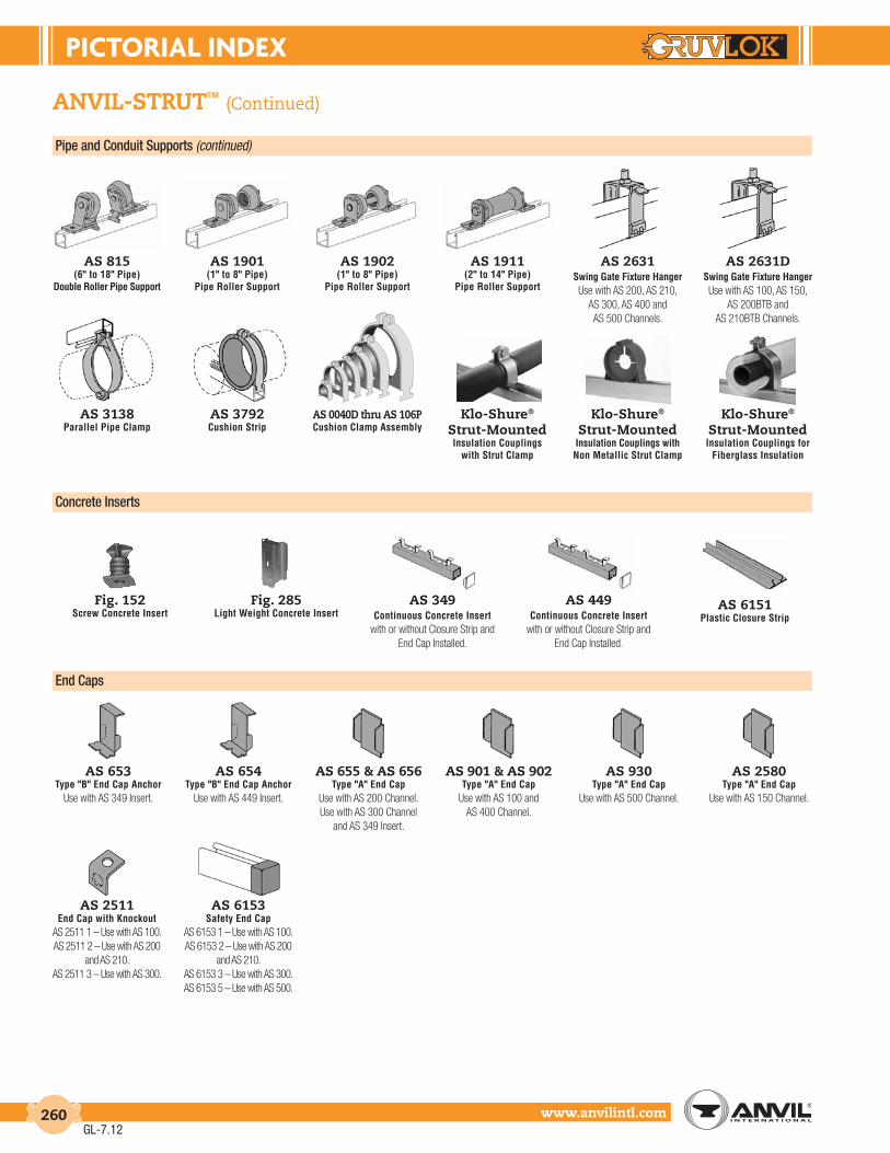
PIctorIAL IndEX
www.anvilintl.com260
anvil-strut™ (Continued)
Pipe and Conduit Supports (continued)
as 815(6" to 18" Pipe)
Double Roller Pipe Support
as 1901(1" to 8" Pipe)
Pipe Roller Support
as 1902(1" to 8" Pipe)
Pipe Roller Support
as 1911(2" to 14" Pipe)
Pipe Roller Support
as 2631Swing Gate Fixture HangerUse with AS 200, AS 210,
AS 300, AS 400 andAS 500 Channels.
as 2631dSwing Gate Fixture HangerUse with AS 100, AS 150,
AS 200BTB andAS 210BTB Channels.
as 3138Parallel Pipe Clamp
as 3792Cushion Strip
as 0040d thru as 106pCushion Clamp Assembly
klo-shure®
strut-mounted Insulation Couplings
with Strut Clamp
Concrete Inserts
fig. 152Screw Concrete Insert
fig. 285Light Weight Concrete Insert
as 349Continuous Concrete Insert
with or without Closure Strip and End Cap Installed.
as 449Continuous Concrete Insert
with or without Closure Strip and End Cap Installed.
as 6151Plastic Closure Strip
as 653Type "B" End Cap Anchor
Use with AS 349 Insert.
as 654Type "B" End Cap Anchor
Use with AS 449 Insert.
as 655 & as 656Type "A" End Cap
Use with AS 200 Channel. Use with AS 300 Channel
and AS 349 Insert.
as 901 & as 902Type "A" End Cap
Use with AS 100 andAS 400 Channel.
as 930Type "A" End Cap
Use with AS 500 Channel.
as 2511End Cap with Knockout
AS 2511 1 – Use with AS 100.AS 2511 2 – Use with AS 200
and AS 210.AS 2511 3 – Use with AS 300.
as 2580Type "A" End Cap
Use with AS 150 Channel.
as 6153Safety End Cap
AS 6153 1 – Use with AS 100.AS 6153 2 – Use with AS 200
and AS 210.AS 6153 3 – Use with AS 300.AS 6153 5 – Use with AS 500.
End Caps
klo-shure®
strut-mounted Insulation Couplings with Non Metallic Strut Clamp
klo-shure®
strut-mounted Insulation Couplings for
Fiberglass Insulation
GL-7.12

nuMErIcAL IndEX
www.anvilintl.com 261
Fig./Model description ................................................Page
171 Brass Ball Valve .......................................... 79-80400G Grooved-End Silent Check Valve ..............83758G Grooved-End “Wye” Strainer .................... 103768G Grooved-End “Wye” Strainer ....................1041007 Roll Groover..............................................148-1491715 Brass Ball Valve .......................................... 79-803006 Roll Groover .............................................150-1513007 Roll Groover..............................................148-1496050 CTS Copper 90˚ Elbow ................................ 1226051 CTS Copper 45˚ Elbow ................................. 1226060 CTS Copper Tee .............................................. 1226061 CTS Copper Reducing Tee (GR x GR x GR) ...1236064 CTS Copper Reducing Tee (GR x GR x CUP) ..1236072 CTS Copper Conc. Reducer (GR x GR) ....... 1246074 CTS Copper End Cap .................................... 122 6075 CTS Copper Red. Adapter (GR x CUP) ........ 1246084 CTS Copper Flange Adapter ...................... 1246400 CTS Copper Rigid Coupling ................121, 1596700 CTS Copper Butterfly Valve .............. 125-1267000 Lightweight Coupling ...................... 26-27, 1577001 Standard Coupling ............................ 21-22, 1547001-2 Standard Coupling ...................................23, 1557003 Hingelok® Coupling ...........................30-31, 1607004 Coupling ...............................................114-115, 1697004 Coupling with EG® Gasket ........... 116-117, 1707005 Roughneck® Coupling .......................... 128, 1687010 Reducing Coupling .............................32-33, 1617011 Standard Coupling ........................... 24-25, 1567012 Gruvlok Flange ........................... 34-36, 162-1647013 Gruvlok Flange .............................................37-397042 Outlet Coupling .................................42-43, 1657044 Branch Outlet ............................................50, 1677045 Clamp-T®, FPT Branch ......................44-46, 1667046 Clamp-T®, Groove Branch .............47-48, 1667047 Clamp-T®, Cross .................................................497048 Clamp-T®, Cross .................................................497049 Clamp-T®, Cross .................................................497050 90° Elbow .............................................................. 527050-3D 90° Long Radius Elbow ...................................677050-5D 90° Long Radius Elbow ...................................687050-6D 90° Long Radius Elbow ...................................697050DR 90° Drain Elbow .................................................657050EG High Pressure 90° LR Elbow ......................... 1187050LR 90° Long Radius Elbow ................................... 537050LRP Plain End 90° Long Radius Elbow ............ 1307050P Plain End 90° Elbow ....................................... 1297050RF Reducing Base Support Elbow (GR x FL) ...627050SS Stainless Steel 90° Elbow-Type 316 ........ 146A7050SS Stainless Steel 90° Elbow-Type 304 ....... 1447051 45° Elbow .............................................................. 527051-3D 45° Long Radius Elbow ...................................677051-5D 45° Long Radius Elbow ...................................687051-6D 45° Long Radius Elbow ...................................697051EG High Pressure 45° LR Elbow ......................... 1187051LR 45° Long Radius Elbow ................................... 537051LRP Plain End 45° Long Radius Elbow ...............1317051P Plain End 45° Elbow ........................................ 1297051SS Stainless Steel 45° Elbow-Type 316 ......... 146A7051SS Stainless Steel 45° Elbow-Type 304 ........ 144
Fig./Model description ................................................Page
7052 221⁄2° Elbow ......................................................... 527052i 221⁄2° Elbow ......................................................... 52 7052-3D 221⁄2° Long Radius Elbow ..............................67 7052-5D 221⁄2° Long Radius Elbow ..............................687052-6D 221⁄2° Long Radius Elbow ..............................697053 111⁄4° Elbow .......................................................... 537053-3D 111⁄4° Long Radius Elbow ................................677053-5D 111⁄4° Long Radius Elbow ................................687053-6D 111⁄4° Long Radius Elbow ................................69 7055 90° Adapter Elbow (GR x MPT) ........................617056 45° Adapter Elbow (GR x MPT) ........................617057-3D 60° Long Radius Elbow ...................................677057-5D 60° Long Radius Elbow ...................................687057-6D 60° Long Radius Elbow ...................................697058-3D 30° Long Radius Elbow ...................................677058-5D 30° Long Radius Elbow ...................................687058-6D 30° Long Radius Elbow ...................................697060 Tee ........................................................................... 557060EG High Pressure Tee ............................................. 1197060P Plain End Tee ..................................................... 1297060SS Stainless Steel Tee-Type 316 ...................... 146A7060SS Stainless Steel Tee-Type 304 ..................... 1447061 Reducing Tee Standard ..................................547061P Plain End Reducing Tee ................................ 1307061SS Stainless Steel Reducing Tee-Type 316.....147A7061SS Stainless Steel Reducing Tee-Type 304 .. 1457062 Bullhead Tee Specialty Tee (GR x GR x FPT) ...657063 Tee w/ Threaded Branch ..............................547064 Reducing Tee w/ Threaded Branch ......... 557065 Standpipe Tee (GR x GR x FPT) .........................657066 Tee Wye ............................................................... 607067 Reducing Tee Wye .......................................... 607068 Cross .......................................................................637068EG High Pressure Cross......................................... 1197068P Plain End Cross ................................................. 1307069 45° Lateral .............................................................597069P Plain End 45° Lateral ....................................... 1307070 45° Reducing Lateral ........................................597071 True Wye ............................................................. 607071P Plain End 90° True Wye ................................ 1307072 Concentric Reducer (GR x GR) .......................587072i Concentric Reducer (GR x GR) .......................58 7072SS Stainless Steel Conc. Reducer-Type 316 ..147A7072SS Stainless Steel Conc. Reducer-Type 304 ..1457073 Eccentric Reducer ............................................567073SS Stainless Steel Ecc. Reducer-Type 316....1477074 Cap ..........................................................................637074SS Stainless Steel Cap-Type 316 ..................... 146A7074SS Stainless Steel Cap-Type 304 .................... 1447075 Bull Plug .................................................................637075P Plain End Bull Plug ............................................1317076 Concentric Reducer (GR x THD) ....................567077 Swaged Nipple (GR x GR) ................................. 577077P Plain End Swaged Nipple .............................1327078 Swaged Nipple (GR x THD) .............................. 577079 Swaged Nipple (GR x BEV) ................................ 577080 Adapter Nipple (GR x GR) ................................647080P Adapter Nipple (Plain x GR) ............................1327081 Adapter Nipple (GR x MPT) .............................64
Fig./Model description ................................................Page
7081P Adapter Nipple (Plain x THD) ........................ 1227082 Adapter Nipple (GR x BEV)...............................647082P Adapter Nipple (Plain x BEV) ...........................1327084 Flange Nipple (GR x #150 FL) .............................627084P Flange Nipple (Plain x #150 FL) ..........................131 7084SS Stainless Steel Flange Adapter ...................... 1477085 Flange Nipple (GR x #300 FL) ............................62 7085P Flange Nipple (Plain x #300 FL) .........................131 7086 HOSE Nipples (GR x Hose) ...............................647087 Female Thread Adapter (GR x FPT) ...............617091 DI-LOK® Nipple (CTS GR x IPS GR) ................ 1277097 Eccentric Reducer ............................................567100 90° Elbow .................................................... 139, 1747101 90° Reducing Elbow .............................. 140, 1747103 Straight Tee ............................................... 140, 1747105 Reducing Outlet Tee ..............................141, 1747106 Reducing Tee..............................................141, 1747107 Coupling ..................................................... 140, 1747240 Expansion Joints .................................40-41, 2137250 Suction Diffuser ..................................... 105-1067260 Tee Strainer ................................................ 101-1027305 HDPE Coupling ..................................133-134, 1717307 HDPE Transition Coupling ..........135-136, 1727312 HDPE Flange Adapter .................... 137-138, 1737400 Rigidlite® Coupling ........................... 28-29, 1587400SS Stainless Steel Rigidlite® Coupling ......... 1427401 Rigidlok® Coupling ..............................18-19, 1537401-2 Rigidlok® Coupling ..................................20, 1557450 90° Short Pattern Elbow ................................667460 Short Pattern Tee ..............................................667500 Ball Valve ........................................................81-827600 Butterfly Valve ................................................... 757662EG High Pressure Header Tee ............................ 1197700 Butterfly Valve ............................................ 70-747800 Check Valve ..................................................84-868000GR Butterfly Valve ............................................ 76-78AF21-FF Flex Connector (FL x FL) .........................110, 182AF21-GF Flex Connector (GR x FL) ........................110, 182AF21-GG Flex Connector (GR x GR) ..................... 109, 182AF21-RFF Reducing Flex Connector (FL x FL).......... 111, 182AF21-RGF Reducing Flex Connector (GR x FL) ....... 112, 182AU KNX Accessory Union .....................90-92, 95CA KNX CBV Accessory ................................. 90-94CU KNX CBV Union ......................................... 90-94FTV-A Tri-Service Valve (Angle) ........99-100, 175-178FTV-S Tri-Service Valve (Straight) ......99-100, 175-178GAV-15 Automatic Air Vent ........................................ 107GAV-30 Automatic Air Vent ........................................108GBV-A Balancing Valve (Angle)..............................87-88GBV-G Balancing Valve (Straight) ..........................87-88GBV-S Circuit Balancing Valve (Sweat) ........89, 179-181GBV-T Circuit Balancing Valve (Threaded) ........89, 179-181SV KNX Integral Ball Valve Strainer ....90-92, 97UV KNX Integral Ball Valve Union ....... 90-92, 96
GL-7.12

tErMS & condItIonS
www.anvilintl.com262
1. CONTROLLING PROVISIONS: These terms and conditions shall control with respect to any purchase order
or sale of Seller’s products. No waiver, alteration or modification of these terms and conditions whether on Buyer’s purchase order or otherwise shall be valid unless the waiver, alteration or modification is specifically accepted in writing and signed by an authorized representative of Seller.
2. DELIVERY: Seller will make every effort to complete delivery of products as indicated on
Seller’s acceptance of an order, but Seller assumes no responsibility or liability, and will accept no backcharge, for loss or damage due to delay or inability to deliver caused by acts of God, war, labor difficulties, accident, delays of carriers, by contractors or suppliers, inability to obtain materials, shortages of fuel and energy, or any other causes of any kind whatever beyond the control of Seller. Seller may terminate any contract of sale of its products without liability of any nature, by written notice to Buyer, in the event that the delay in delivery or performance resulting from any of the aforesaid causes shall continue for a period of sixty (60) days. Under no circumstances shall Seller be liable for any special or consequential damages or for loss, damage, or expense (whether or not based on negligence) directly or indirectly arising from delays or failure to give notice of delay.
3. WARRANTY: Seller warrants for one year from the date of shipment Seller’s manufactured
products to the extent that Seller will replace those having defects in material or workmanship when used for the purpose and in the manner which Seller recommends. If Seller examination shall disclose to its satisfaction that the products are defective, and an adjustment is required, the amount of such adjustment shall not exceed the net sales price of the defective products only and no allowance will be made for labor or expense of repairing or replacing defective products or workmanship of damage resulting from the same. Seller warrants the products which it sells of other manufacturers to the extent of the warranties of their respective makers. Where engineering design or fabrication work is supplied. Buyer’s acceptance of Seller’s design or of delivery of work shall relieve Seller of all further obligation, other than expressed in Seller’s product warranty. THIS IS SELLER’S SOLE WARRANTY. SELLER MAKES NO OTHER WARRANTY OF ANY KIND, EXPRESSED OR IMPLIED AND ALL IMPLIED WARRANTIES OF MERCHANTABILITY AND FOR A PARTICULAR PURPOSE WHICH EXCEED SELLER’S AFORESTATED OBLIGATION ARE HEREBY DISCLAIMED BY SELLER AND EXCLUDED FROM THIS WARRANTY. Seller neither assumes, nor authorizes any person to assume for it, any other obligation in connection with the sale of its engineering designs or products. This warranty shall not apply to any products or parts of products which (a) have been repaired or altered outside of Seller’s factory, in any manner: (b) have been subjected to misuse, negligence or accidents; (c) have been used in a manner contrary to Seller’s instructions or recommendations. Seller shall not be responsible for design errors due to inaccurate or incomplete information supplied by Buyer or its representatives.
4. SELLER’S LIABILITY: Seller will not be liable for any loss, damage, cost of repairs, incidental or
consequential damages of any kind, whether based upon warranty (except for the obligation accepted by Seller under “Warranty” above), contract or negligence, arising in connection with the design, manufacture, sale, use or repair of the products or of the engineering designs supplied to Buyer.
5. RETURNS: Seller cannot accept return of any products unless its written permission has
been first obtained, in which case same will be credited subject to the following (a) All material returned must, on its arrival at Seller’s Plant, be found to be in first-class condition; if not, cost of putting in saleable condition will be deducted from credit memoranda; (b) A handling charge deduction of twenty percent (20%) will be made from all credit memoranda issued for material returned; (c) Transportation charges, if not prepaid will be deducted from credit memoranda.
6. SHIPMENTS: All products sent out will be carefully examined, counted and packed. The cost
of any special packing or special handling caused by Buyer’s requirements or requests shall be added to the amount of the order. No claim for shortages will be allowed unless made in writing within ten (10) days of receipt of a shipment.
Claims for products damaged or lost in transit should be made on the carrier, as Seller’s responsibility ceases, and title passes, on delivery to the carrier.
7. SPECIAL PRODUCTS: Orders covering special or nonstandard products are not subject to
cancellation except on such terms as Seller may specify on application.
8. PRICES AND DESIGNS: Prices and designs are subject to change without notice. All prices are F.O.B.
Point of shipment, unless otherwise stated.
9. TAXES: The amount of any sales, excise or other taxes, if any, applicable to the
products covered by this order, shall be paid by Buyer unless Buyer provides Seller with an exemption certificate acceptance to the taxing authorities.
10. NUCLEAR PLANTS: Where the products, engineering design or fabrication is for nuclear plant
applications. Buyer agrees (a) to take all necessary steps to add Seller as an insured under the American Nuclear Insurers’ (ANI) pool and under the Mutual Atomic Energy Reinsurance Pool (MAERP) for property damage and liability insurance and if necessary steps could have been taken, but are not taken, Buyer shall hold Seller harmless against all such losses which could have been thus covered (b) Buyer agrees to hold Seller harmless with respect to any personal injury (or death), property damage or other loss in a nuclear incident which is caused directly or indirectly by defective design, material, workmanship furnished by Buyer (or which could be so covered but with respect to which Buyer has elected to self-insure), and further agrees to waive subrogation by its carriers of such insurance against Seller, and (c) as to nuclear hazards for which Buyer cannot obtain insurance coverage, the liability of Seller for any personal injury (or death), property damage or other loss directly caused by defective design, material, or workmanship furnished by Seller shall not exceed the value at the time of the loss occurrence.
11. MINIMUM INVOICE: Domestic: $100 plus transportation. International: $500 plus transportation.
12. TERMS: Cash, net 30 days unless otherwise specified.
NOTE: All orders are accepted on the basis of prices in effect at the time of
shipment.
NOTICE: The prices and terms quoted, there will be added any manufacturers
or sales tax payable on the transaction under any effective statute.
FREIGHT ALLOWANCE: All prices are F.O.B. point of shipment. On shipments
weighing 2,500 pounds or more, rail freight or motor freight at the lowest
published rate, is allowed to all continental U.S. rail points or all U.S. highway
points listed in published tariffs (Alaska and Hawaii excluded). In no case will
more than actual freight be allowed. Shipments (weighing less than 2,500
pounds) will be shipped prepaid. The buyer will be invoiced for freight costs
at the applicable published class, exception or commodity rate(s) or charge(s).
Anvil reserves the right to select the carrier for all shipments.
GL-6.11

GruVLoK croSS rEFErEncE
www.anvilintl.com 263
Victaulic® Gruvlok® couplings & Gaskets07/107 7400 Rigidlite® Coupling07/107 7401 Rigidlok® Coupling45/46 7084/7085 Flg x Grv Adapter-150/300#
72 7042FF Outlet Coupling fnpt75 7000 Lt. Wt. Flexible Coupling77 7001 Flexible Coupling78 7003 Hinge Coupling99 7005 Rough Neck Coupling
741/743 7012/7013 Grooved Flange-150/300#995/997 7305/7307 HDPE Coupling
ES EG End Guard GasketFS FG Flush Gap Gasket
Grade E Grade E Gasket EPDMGrade L Grade L Gasket SiliconeGrade O Grade O Gasket VitonGrade T Grade T Gasket NitrileHP-70 7004HPR HPR Coupling
HP-70ES 7004EG End Guard CouplingNA 7400 300 p.s.i. Rigid Coupling
Victaulic® Gruvlok® Mechanical47 7088/7089 Di-Electric Nipple155 7240 Expansion Joint300 7700 Butterfly Valves416 400G Large Silent Check Valve700 7600 Butterfly Valve709 8000 Large Butterfly Valve716 7811 Check Valve721 7500 Ball Valve730 7260 Tee Strainer731 7250 Suction Diffuser732 758, 768 Wye Strainer733 Available Venturi - Grooved789 GBV-G Balancing ValveNA 722 Triple Service ValveNA SF21-GF Flex Connector, F x G
R-10F 7050RF Base Ell Reducing, F x GVE272 3006/C Grooving ToolsVE416 3007 Grooving Tools
copper Victaulic® Gruvlok® ctS copper Product
606/607 6400 Rigid Coupling - Copper608 7721 Copper Butterfly Valve610 6050 Copper 90˚ Ell611 6051 Copper 45˚ Ell620 6060 Copper Tee625 6061 Copper Reducing Tee, G x G626 6064 Copper Reducing Tee, G x C641 6084 Flange - Copper650 6072 Copper Conc. Reducer, G x G652 6075 Copper Conc. Reducer, G x C660 6074 Copper CapNA 7500B Copper Ball Valve
Victaulic® Gruvlok® Fittings10 7050 90˚ Ell
10-P 7050P Plain-End 90˚ Ell11 7051 45˚ Ell12 7052 221/2˚ Ell13 7053 111/4˚ Ell20 7060 Tee25 7061 Reducing Tee
29M 7063 Tee with Threaded Branch29T 7064 Reducing Tee with Threaded Branch30 7069 Lateral 45˚
30R 7070 Reducing Lateral 45˚32 7066 True Wye
32R 7067 Reducing Tee Wye33 7071 True Wye
43/40 7080/7081 Nipples, G x G/G x T50 7072 Concentric Reducer51 7073 Eccentric Reducer52 7076 Reducer Groove x Thread53 7077 Swaged Reducer Nipple60 7074 Cap80 7087 Female Threaded Adapter100 7050LR Long Radius 90˚ Ell110 7051LR Long Radius 45˚ Ell
Victaulic® Gruvlok® Fire Protection001 7450 90˚ Ell (Short Pattern)002 7460 Tee (Short Pattern)75 7000A Lt. Wt. Flexible Coupling
005 7400A Lt. Wt. Rigid Sprinkler Coupling27 7065 Standpipe Tee61 7075 Bull Plug96 7105 Sock-It® Reducing Tee
705W 7722-3D UL/FM Butterfly Valve w/s717 78FP UL/FM Valve750 7010 Reducing Coupling920 7045 Clamp Tee Fnpt Outlet920 7046 Clamp Tee Grooved Outlet920 7048 Clamp Cross925 7044 Econ. Clamp Tee Fnpt961 7100 Sock-It® 90˚ Ell
Victaulic® Gruvlok® Stainless Steel489 7400SS Rigid Coupling - 316SS89 7401 Rigid Coupling - Ductile Iron
20-SS 7060-SS04 Sch. 10 Tee 304L20-SS-SW 7061-SS04 Sch. 10 Reducing Tee 304L50-SSLT 7072-SS04 Sch. 10 Conc. Reducer 304L51-SSLT 7073-SS04 Sch. 10 Ecc. Reducer 304L60-SS 7074-SS04 Sch. 10 Cap 304L100-SS 7050-SS04 Sch. 10 90˚ Ell 304L110-SS 7051-SS04 Sch. 10 45˚ Ell 304L721S 7500SS SS Ball Valve
GL-6.11

notES
www.anvilintl.com264
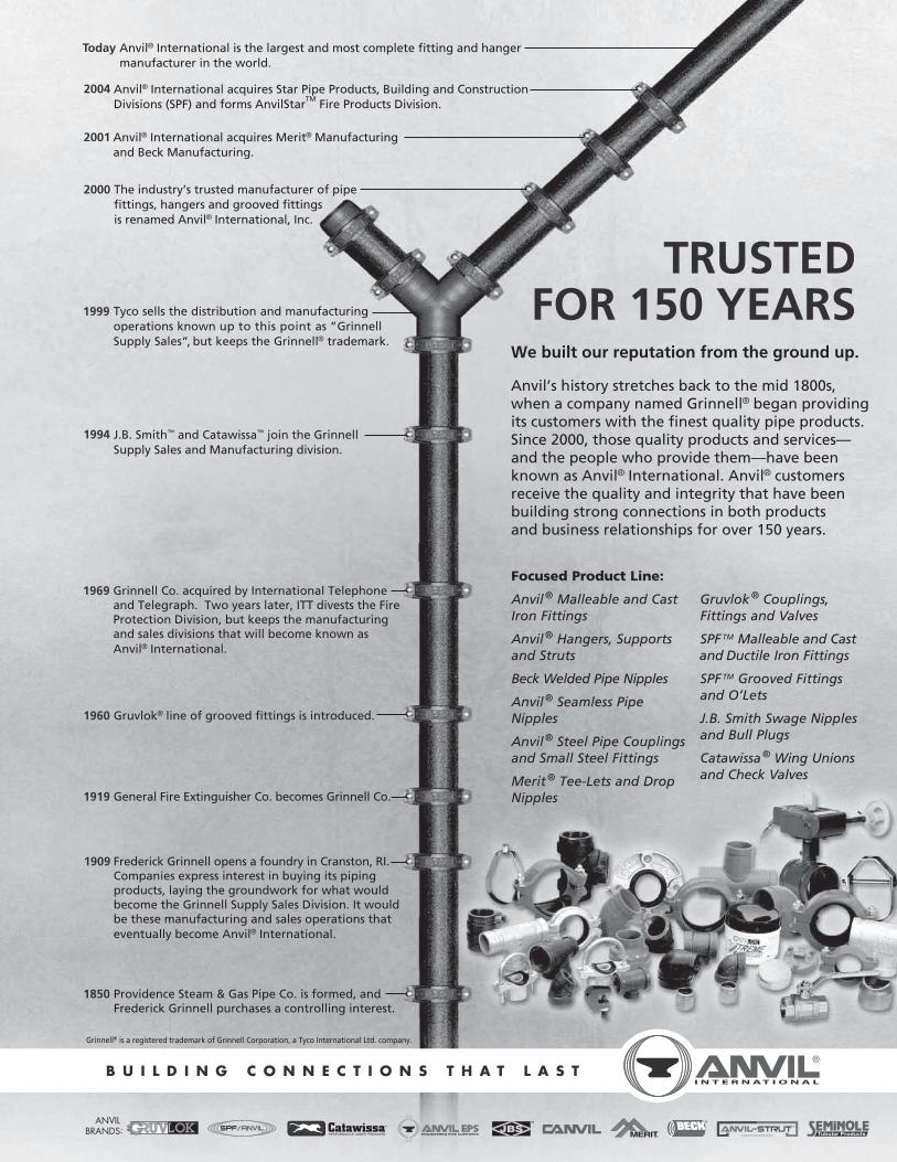
B U I L D I N G C O N N E C T I O N S T H A T L A S T
We built our reputation from the ground up.
Anvil’s history stretches back to the mid 1800s,when a company named Grinnell® began providingits customers with the finest quality pipe products.Since 2000, those quality products and services—and the people who provide them—have beenknown as Anvil® International. Anvil® customers receive the quality and integrity that have been building strong connections in both productsand business relationships for over 150 years.
TRUSTEDFOR 150 YEARS
Focused Product Line:
Anvil® Malleable and CastIron Fittings
Anvil® Hangers, Supportsand Struts
Beck Welded Pipe Nipples
Anvil® Seamless PipeNipples
Anvil® Steel Pipe Couplingsand Small Steel Fittings
Merit® Tee-Lets and DropNipples
Gruvlok® Couplings,Fittings and Valves
SPFTM Malleable and Castand Ductile Iron Fittings
SPF TM Grooved Fittings and O’Lets
J.B. Smith Swage Nipplesand Bull Plugs
Catawissa® Wing Unionsand Check Valves
Today Anvil® International is the largest and most complete fitting and hanger manufacturer in the world.
2004 Anvil® International acquires Star Pipe Products, Building and Construction Divisions (SPF) and forms AnvilStar
TM Fire Products Division.
2001 Anvil® International acquires Merit® Manufacturingand Beck Manufacturing.
2000 The industry’s trusted manufacturer of pipefittings, hangers and grooved fittingsis renamed Anvil® International, Inc.
1999 Tyco sells the distribution and manufacturingoperations known up to this point as ”Grinnell Supply Sales”, but keeps the Grinnell® trademark.
1994 J.B. Smith™ and Catawissa™ join the Grinnell Supply Sales and Manufacturing division.
1850 Providence Steam & Gas Pipe Co. is formed, andFrederick Grinnell purchases a controlling interest.
1909 Frederick Grinnell opens a foundry in Cranston, RI.Companies express interest in buying its pipingproducts, laying the groundwork for what wouldbecome the Grinnell Supply Sales Division. It would be these manufacturing and sales operations thateventually become Anvil® International.
1919 General Fire Extinguisher Co. becomes Grinnell Co.
1960 Gruvlok® line of grooved fittings is introduced.
1969 Grinnell Co. acquired by International Telephone and Telegraph. Two years later, ITT divests the FireProtection Division, but keeps the manufacturingand sales divisions that will become known asAnvil® International.
Grinnell® is a registered trademark of Grinnell Corporation, a Tyco International Ltd. company.
ANVIL BRANDS:
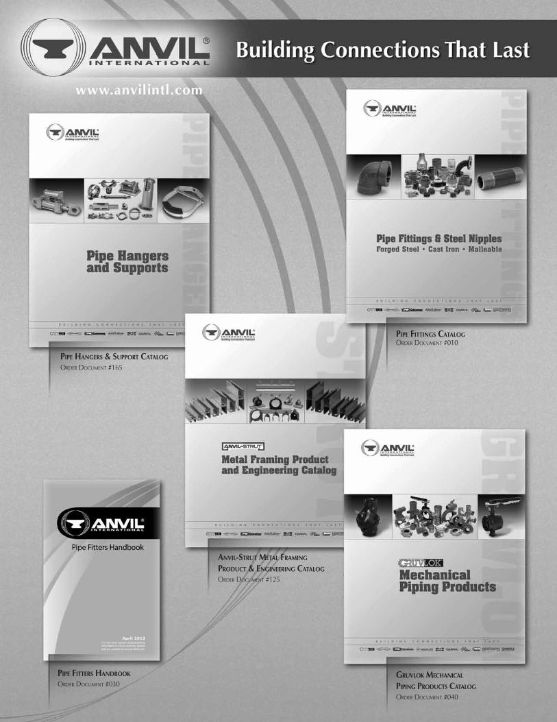
PiPe Hangers & suPPort Catalog
Order dOcument #165
gruvlok MeCHaniCal
PiPing ProduCts Catalog
Order dOcument #040
PiPe Fittings Catalog Order dOcument #010
anvil-strut Metal FraMing
ProduCt & engineering Catalog
Order dOcument #125
PiPe Fitters Handbook
Order dOcument #030
Anvil® product lines include malleable and cast iron fittings, unions and flanges; seamless and welded steel pipe nipples; steel pipe couplings; universal anvilets; forged steel fittings and unions; pipe hangers and supports; threaded rod; and engineered hangers.
The Gruvlok® product line consists of couplings for grooved and plain-end fittings, butterfly valves and check valves; flanges; pump protection components; pipe grooving tools; as well as copper and stainless steel system components.
Anvil-Strut™ products include a complete line of channel in stock lengths of 10 and 20 feet, with custom lengths available upon request. A variety of fittings and accessories are also offered. All products can be ordered in an assortment of finishes and material choices including SupR-Green™, Zinc Trivalent Chromium, pre-galvanized, hot-dip galvanized, electro-galvanized, aluminum, plain, and stainless steel.
JB Smith™ is the leading manufacturer of oil country tubular fittings, swages and bull plugs – all meeting API specifications. Offering tubing nipples, casing nipples as well as a full line of traditional line pipe and oil country threads in every schedule, JB Smith is the resource for all your oilfield needs.
Catawissa™ NACE and API approved wing unions for Standard Service are offered in non-pressure seal ends as well as threaded and butt weld, and are interchangeable with most leading union manufacturers. Fully traceable and available with complete mill certifications, Catawissa’s oilfield wing union product line includes the standard ball-and-cone design plus our unique Figure 300 Flat Face design, where space and pipe line separation are a consideration.
B u i l d i n G c o n n e c t i o n s t h At l A s t
For over 150 years, Anvil has worked diligently to build a strong, vibrant tradition of making connections — pipe to pipe and people to people.
We pride ourselves in providing the finest-quality pipe products and
services with integrity and dedication to superior customer service at all levels.
We provide expertise and product solutions for a wide range of applications,
from plumbing, mechanical, HVAC, industrial and fire protection to mining,
oil and gas. Our comprehensive line of products includes: grooved pipe
couplings, grooved and plain-end fittings, valves, cast and malleable iron fittings,
forged steel fittings, steel pipe nipples and couplings, pipe hangers and supports,
channel and strut fittings, mining and oil field fittings, along with much more.
As an additional benefit to our customers, Anvil offers a complete and
comprehensive Design Services Analysis for mechanical equipment rooms, to
help you determine the most effective and cost-efficient piping solutions.
At Anvil, we believe that responsive and accessible customer support is
what makes the difference between simply delivering products —
and delivering solutions.
B r A n d s o f A n v i l i n t e r n At i o n A l
The SPF/Anvil™ product line includes a variety of internationally sourced products such as grooved couplings, fittings and flanges, cast iron, malleable iron and ductile iron threaded fittings, steel pipe nipples, as well as o’lets.
The Merit® product line includes a variety of tee-lets, drop nipples, and steel welding flanges for fire protection applications. Most Merit products are UL/ULC Listed, FM Approved, and rated from 175 to 300 psi.
Steel pipe nipples and steel pipe couplings are manufactured in accordance with the ASTM A733 Standard Specification for Welded and Seamless Carbon Steel and Stainless Steel Pipe Nipples. Steel pipe couplings are manufactured in accordance with the ASTM A865 Standard Specification for Threaded Couplings, Steel, Black or Zinc-Coated (Galvanized) Welded or Seamless, for Use in Steel Pipe Joints. API couplings are manufactured in accordance with the API Specification for line pipe.
Canvil® manufactures low pressure hexagon reducer bushings, as well as plugs and hex caps up to 1” in diameter in various finishes including Oil Treat, Phosphate and Electro Galvanized. In addition, Canvil manufactures A105 hex or round material in class 3000 and 6000 pound, forged steel couplings and bar stock products offered as either as normalized (A105N) or non-normalized (A105) that are fully traceable for mechanicals and chemistry through our MTR program.
Anvil EPS-Engineered Pipe Supports are products used to support piping systems under thermal, seismic, and other dynamic loading conditions. The product line encompasses variable spring hangers, constant supports, sway struts and snubbers as well as standard and special design clamps. Anvil EPS brings the highest quality products and innovative engineering solutions to common and uncommon piping system problems.

b u i l d i n g c o n n e c t i o n s t h a t l a s t
Mechanical P
iping Products C
atalogA
nv
il intern
Ation
Al
#040/Printed in USA/© Copyright 2012Revision Date: 6.19.12
MechanicalPiping Products
7/12
July 2012For the most current product/pricing information on Anvil products, please visit our website at www.anvilintl.com.
europe And middle eAstTel: +31-53-5725570 • Fax: +31-53-5725579International Customer ServiceTel: +1-708-885-3000 • Fax: +1-708-534-5441
mexico, puerto rico And lAtin AmericAInternational Customer ServiceTel: +1-708-885-3000 • Fax: +1-708-534-5441
corporAte offices2 Holland WayExeter, NH 03833Tel: 603-422-8000 • Fax: 603-422-8033E-mail: [email protected]
customer service centers
www.anvilintl.com
b u i l d i n g c o n n e c t i o n s t h a t l a s t
united stAtesUniversity Park, ILTel: 708-885-3000 • Fax: 708-534-5441 Toll Free: 1-800-301-2701
Irving, TXTel: 972-871-1206 • Fax: 972-641-8946 Toll Free: 1-800-451-4414
cAnAdASimcoe, OntarioTel: 519-426-4551 • Fax: 519-426-5509
u.s. reGionAl distriBution centers
universitY pArK750 Central Avenue University Park, IL 60484
irvinG1401 Valley View Lane, Suite 150Irving, TX 75061
columBiA800 Malleable RoadColumbia, PA 17512
ontArio1470 S. Vintage AvenueOntario, CA 91761
Engineered Pipe SupportsCustomer Service Center160 Frenchtown RoadNorth Kingstown, RI 02852Tel: 401-886-3000 Fax: 401-886-3010Toll Free: 1-877-406-3108
Anvil eps
additional inventorY locAtions*
united stAtes: Arizona, Colorado, Georgia, Indiana, Massachusetts, Minnesota, Missouri, New York, Tennessee, Texas, Washington and Wisconsin
internAtionAl: Ontario, Canada and Waalwijk, Netherlands
*Inventory varies at locations