GRUNDFOS DATA BOOKLET - Pumpegruppen€¦ · DDI Product family Model Pump type Connection size DDI...
113
Accessories for dosing pumps GRUNDFOS DATA BOOKLET
Transcript of GRUNDFOS DATA BOOKLET - Pumpegruppen€¦ · DDI Product family Model Pump type Connection size DDI...

Accessories for dosing pumps
GRUNDFOS DATA BOOKLET

1. Pump connection sizes by pump types . . . . . . . . . . . . . . . . . . . . . . . . . . . . . . . . . . . . . . . . . . . . . . . 4
2. Hydraulic accessories for pump connection size G 5/8 . . . . . . . . . . . . . . . . . . . . . . . . . . . . . . . . . . 7Overview of accessories for pump connection size G 5/8 . . . . . . . . . . . . . . . . . . . . . . . . . . . . . . . . . . . . . . . . . 7Installation kits for pump connection size G 5/8. . . . . . . . . . . . . . . . . . . . . . . . . . . . . . . . . . . . . . . . . . . . . . . . 8Hoses for pump connection size G 5/8. . . . . . . . . . . . . . . . . . . . . . . . . . . . . . . . . . . . . . . . . . . . . . . . . . . . . . 9Foot valves FV . . . . . . . . . . . . . . . . . . . . . . . . . . . . . . . . . . . . . . . . . . . . . . . . . . . . . . . . . . . . . . . . . . . . . 11Rigid suction lances RSL . . . . . . . . . . . . . . . . . . . . . . . . . . . . . . . . . . . . . . . . . . . . . . . . . . . . . . . . . . . . . . 13Accessories for rigid suction lances RSL and foot valves FV. . . . . . . . . . . . . . . . . . . . . . . . . . . . . . . . . . . . . . 16Injection units . . . . . . . . . . . . . . . . . . . . . . . . . . . . . . . . . . . . . . . . . . . . . . . . . . . . . . . . . . . . . . . . . . . . . . 18Multi-function valves, pressure relief valves, pressure loading valves. . . . . . . . . . . . . . . . . . . . . . . . . . . . . . . . 21Pulsation dampers and calibration columns . . . . . . . . . . . . . . . . . . . . . . . . . . . . . . . . . . . . . . . . . . . . . . . . . 26Accessories for hydraulic connection . . . . . . . . . . . . . . . . . . . . . . . . . . . . . . . . . . . . . . . . . . . . . . . . . . . . . . 32
3. Hydraulic accessories for pump connection size G 5/4 . . . . . . . . . . . . . . . . . . . . . . . . . . . . . . . . . 37Overview of accessories for pump connection size G 5/4 . . . . . . . . . . . . . . . . . . . . . . . . . . . . . . . . . . . . . . . . 37Hoses for pump connection size G 5/4. . . . . . . . . . . . . . . . . . . . . . . . . . . . . . . . . . . . . . . . . . . . . . . . . . . . . 38Foot valves FV . . . . . . . . . . . . . . . . . . . . . . . . . . . . . . . . . . . . . . . . . . . . . . . . . . . . . . . . . . . . . . . . . . . . . 39Rigid suction lances RSL . . . . . . . . . . . . . . . . . . . . . . . . . . . . . . . . . . . . . . . . . . . . . . . . . . . . . . . . . . . . . . 40Injection units . . . . . . . . . . . . . . . . . . . . . . . . . . . . . . . . . . . . . . . . . . . . . . . . . . . . . . . . . . . . . . . . . . . . . . 44Pressure relief valves and pressure loading valves . . . . . . . . . . . . . . . . . . . . . . . . . . . . . . . . . . . . . . . . . . . . 46Pulsation dampers and calibration columns . . . . . . . . . . . . . . . . . . . . . . . . . . . . . . . . . . . . . . . . . . . . . . . . . 50Accessories for hydraulic connection . . . . . . . . . . . . . . . . . . . . . . . . . . . . . . . . . . . . . . . . . . . . . . . . . . . . . . 56Preassembled accessories set for SMART Digital XL . . . . . . . . . . . . . . . . . . . . . . . . . . . . . . . . . . . . . . . . . . 58
4. Hydraulic accessories for pump connection size G 2. . . . . . . . . . . . . . . . . . . . . . . . . . . . . . . . . . . 60Overview of accessories for pump connection size G 2 . . . . . . . . . . . . . . . . . . . . . . . . . . . . . . . . . . . . . . . . . 60Hoses for dosing pump connection size G 2 . . . . . . . . . . . . . . . . . . . . . . . . . . . . . . . . . . . . . . . . . . . . . . . . . 61Foot valves FV with connection size G 2 . . . . . . . . . . . . . . . . . . . . . . . . . . . . . . . . . . . . . . . . . . . . . . . . . . . 61Rigid suction lances RSL with connection size G 2 . . . . . . . . . . . . . . . . . . . . . . . . . . . . . . . . . . . . . . . . . . . . 62Injection units for pump connection size G 2 . . . . . . . . . . . . . . . . . . . . . . . . . . . . . . . . . . . . . . . . . . . . . . . . . 63Pressure loading valves PLV . . . . . . . . . . . . . . . . . . . . . . . . . . . . . . . . . . . . . . . . . . . . . . . . . . . . . . . . . . . 64Pulsation dampers . . . . . . . . . . . . . . . . . . . . . . . . . . . . . . . . . . . . . . . . . . . . . . . . . . . . . . . . . . . . . . . . . . 65Accessories for hydraulic connection . . . . . . . . . . . . . . . . . . . . . . . . . . . . . . . . . . . . . . . . . . . . . . . . . . . . . . 70
5. Hydraulic accessories for DMH 28x high-pressure pumps. . . . . . . . . . . . . . . . . . . . . . . . . . . . . . . 73Guide to find suitable suction-side accessories for DMH 28x dosing pumps . . . . . . . . . . . . . . . . . . . . . . . . . . . 73Injection units for DMH 28x high-pressure dosing pumps . . . . . . . . . . . . . . . . . . . . . . . . . . . . . . . . . . . . . . . . 74Pressure relief valves PRV for DMH 28x high-pressure dosing pumps . . . . . . . . . . . . . . . . . . . . . . . . . . . . . . . 75Pulsation dampers for DMH 28x high-pressure dosing pumps. . . . . . . . . . . . . . . . . . . . . . . . . . . . . . . . . . . . . 76Pump connection kits for DMH 28x high-pressure dosing pumps. . . . . . . . . . . . . . . . . . . . . . . . . . . . . . . . . . . 79
6. Hydraulic accessories for DMX 227 dosing pumps. . . . . . . . . . . . . . . . . . . . . . . . . . . . . . . . . . . . . 80Injection units for DMX 227 . . . . . . . . . . . . . . . . . . . . . . . . . . . . . . . . . . . . . . . . . . . . . . . . . . . . . . . . . . . . 80Pressure relief valves for DMX 227 . . . . . . . . . . . . . . . . . . . . . . . . . . . . . . . . . . . . . . . . . . . . . . . . . . . . . . . 80Pressure loading valves for DMX 227 . . . . . . . . . . . . . . . . . . . . . . . . . . . . . . . . . . . . . . . . . . . . . . . . . . . . . 82Pulsation dampers DB and DBG for DMX 227 . . . . . . . . . . . . . . . . . . . . . . . . . . . . . . . . . . . . . . . . . . . . . . . 82Pump connection kits and inlay kits for DMX 227 . . . . . . . . . . . . . . . . . . . . . . . . . . . . . . . . . . . . . . . . . . . . . 84
7. General accessories . . . . . . . . . . . . . . . . . . . . . . . . . . . . . . . . . . . . . . . . . . . . . . . . . . . . . . . . . . . . . 85Dosing tanks . . . . . . . . . . . . . . . . . . . . . . . . . . . . . . . . . . . . . . . . . . . . . . . . . . . . . . . . . . . . . . . . . . . . . . 85Tank accessories . . . . . . . . . . . . . . . . . . . . . . . . . . . . . . . . . . . . . . . . . . . . . . . . . . . . . . . . . . . . . . . . . . . 92Pump mounting accessories. . . . . . . . . . . . . . . . . . . . . . . . . . . . . . . . . . . . . . . . . . . . . . . . . . . . . . . . . . . . 99Accessories for pulsation dampers and calibration columns . . . . . . . . . . . . . . . . . . . . . . . . . . . . . . . . . . . . 100Cables and plugs for dosing pumps. . . . . . . . . . . . . . . . . . . . . . . . . . . . . . . . . . . . . . . . . . . . . . . . . . . . . 103E-box for SMART Digital S DDA . . . . . . . . . . . . . . . . . . . . . . . . . . . . . . . . . . . . . . . . . . . . . . . . . . . . . . . 106
Accessories for dosing pumps
2
Table of contents
Water meters . . . . . . . . . . . . . . . . . . . . . . . . . . . . . . . . . . . . . . . . . . . . . . . . . . . . . . . . . . . . . . . . . . . . 108Diaphragm leakage sensor for DME pumps . . . . . . . . . . . . . . . . . . . . . . . . . . . . . . . . . . . . . . . . . . . . . . . 110Dosing monitor for DME pumps . . . . . . . . . . . . . . . . . . . . . . . . . . . . . . . . . . . . . . . . . . . . . . . . . . . . . . . 110
8. Grundfos Product Center . . . . . . . . . . . . . . . . . . . . . . . . . . . . . . . . . . . . . . . . . . . . . . . . . . . . . . . . 112
Accessories for dosing pumps
3
Tabl
e of
con
tent
s
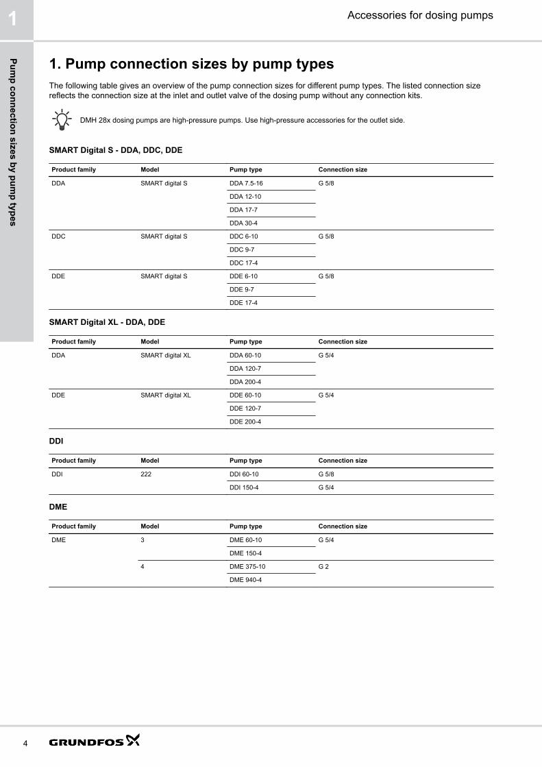
1. Pump connection sizes by pump typesThe following table gives an overview of the pump connection sizes for different pump types. The listed connection sizereflects the connection size at the inlet and outlet valve of the dosing pump without any connection kits.
DMH 28x dosing pumps are high-pressure pumps. Use high-pressure accessories for the outlet side.
SMART Digital S - DDA, DDC, DDE
Product family Model Pump type Connection size
DDA SMART digital S DDA 7.5-16 G 5/8
DDA 12-10
DDA 17-7
DDA 30-4
DDC SMART digital S DDC 6-10 G 5/8
DDC 9-7
DDC 17-4
DDE SMART digital S DDE 6-10 G 5/8
DDE 9-7
DDE 17-4
SMART Digital XL - DDA, DDE
Product family Model Pump type Connection size
DDA SMART digital XL DDA 60-10 G 5/4
DDA 120-7
DDA 200-4
DDE SMART digital XL DDE 60-10 G 5/4
DDE 120-7
DDE 200-4
DDI
Product family Model Pump type Connection size
DDI 222 DDI 60-10 G 5/8
DDI 150-4 G 5/4
DME
Product family Model Pump type Connection size
DME 3 DME 60-10 G 5/4
DME 150-4
4 DME 375-10 G 2
DME 940-4
Accessories for dosing pumps1
4
Pump connection sizes by pum
p types

DMH
Product family Model Pump type Connection size
DMH 251, 252 DMH x-x G 5/8
DMH 253, 254 DMH x-x G 5/4
DMH 255 DMH x-x G 5/4*
DMH 257 DMH x-x Flange DN 32, accessories for G 2 are suitable.
DMH 280 DMH x-x G 3/8**
Use an adapter on the suction side to convert to G 5/8 anduse G 5/8 accessories.2.10.3 Threaded adapters G 3/8 on page 34
DMH 281 DMH x-x G 5/8**
DMH 283, 285, 286 DMH x-x G 5/4**
DMH 287, 288 DMH x-x G 5/8**
* Pump types DMH 270-10 and DMH 550-10 have a DN 32 flange on the inlet side** Use high-pressure accessories for the outlet side
DMX
Product family Model Pump type Connection size
DMX 221 (pre-selected) DMX 16-12 G 5/8
DMX 27-12
DMX 50-10
DMX 115-3 G 5/4
DMX 221 DMX 4-10 G 5/8
DMX 7-10
DMX 8-10
DMX 9-10
DMX 12-10
DMX 14-10
DMX 16-10
DMX 17-4 G 5/4
DMX 18-10 G 5/8
DMX 25-3 G 5/4
DMX 26-10 G 5/8
DMX 27-10
DMX 35-10
DMX 39-4 G 5/4
DMX 50-10 G 5/8
DMX 60-3 G 5/4
DMX 75-4
DMX 115-3
DMX 226 (pre-selected) DMX 132-10 G 5/4
DMX 199-8
DMX 280-8
DMX 321-6
DMX 460-6
DMX 525-3 G 2
DMX 765-3
Accessories for dosing pumps 1
5
Pum
p co
nnec
tion
size
s by
pum
p ty
pes

Product family Model Pump type Connection size
DMX 226 DMX 24-8 G 5/4
DMX 37-5
DMX 52-8
DMX 60-3
DMX 67-10
DMX 82-5
DMX 95-8
DMX 100-8
DMX 130-3
DMX 132-10
DMX 142-8
DMX 152-6
DMX 160-5
DMX 190-10
DMX 199-8
DMX 230-5
DMX 249-3 G 2
DMX 255-3 G 5/4
DMX 280-8
DMX 315-3 G 2
DMX 321-6 G 5/4
DMX 380-3
DMX 460-6
DMX 525-3 G 2
DMX 765-3
DMX 227 DMX x-x Flange DN 65. See accessories for DMX 227.
Accessories for dosing pumps1
6
Pump connection sizes by pum
p types

2. Hydraulic accessories for pump connection size G 5/8
Overview of accessories for pump connection size G 5/8Grundfos offer a comprehensive range of accessories covering every need when dosing with Grundfos pumps.
P
1
2
6
7
8
10
4
9
5
3
TM07
0284
Pos. Description See section
1 Injection units Injection units on page 18
2 Hoses Hoses for pump connection size G 5/8 on page 9
3 Multi-function valve, pressure loading valves, pressure reliefvalves, pressure valves
Multi-function valves MFV on page 21Pressure relief valves PRV on page 23Pressure loading valves PLV on page 24Pressure valves PV on page 25
4 Example: SMART Digital S dosing pump
5 Cables Cables and plugs for pump connection size G 5/8 on page 104
6 E-box E-box for SMART Digital S DDA on page 106
7 Dosing tanks Square tank on page 85Cylindrical tanks on page 86
8 Handheld mixer Tank accessories on page 92
Accessories for dosing pumps 2
7
Hyd
raul
ic a
cces
sorie
s fo
r pum
p co
nnec
tion
size
G 5
/8

Pos. Description See section
9 Rigid suction lances and foot valves Order data for rigid suction lances RSL with connection size G 5/8 on page 13Order data for foot valves FV with connection size G 5/8 on page 11
10 Drain valve Tank accessories on page 92
- Installation kits Installation kits for pump connection size G 5/8 on page 8
- Accessories for hydraulic connection Pump connection kits and inlay kits for pump connection size G 5/8 on page 32Threaded adapters G 5/8 on page 33Threaded adapters G 3/8 on page 34Adapters G 5/8 on page 34T-piece adapters G 5/8 on page 36
Installation kits for pump connection size G 5/8The delivery includes:
• Injection unit with spring-loaded non-return valve
• PE outlet hose, 6 m
• PVC inlet hose, 2 m
• PVC deaeration hose, 2 m
• PE foot valve with strainer and weight, without or with level indication
TM04
1600
Fig. Installation kit with foot valve without levelindication
TM04
8469
Fig. Installation kit with foot valve with level indication
Accessories for dosing pumps2
8
Hydraulic accessories for pum
p connection size G 5/8
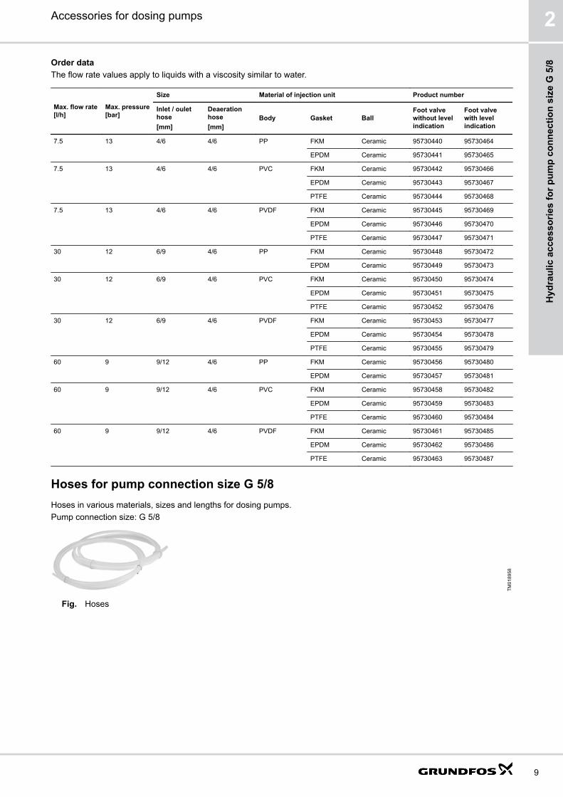
Order dataThe flow rate values apply to liquids with a viscosity similar to water.
Max. flow rate[l/h]
Max. pressure[bar]
Size Material of injection unit Product number
Inlet / oulethose[mm]
Deaerationhose[mm]
Body Gasket BallFoot valvewithout levelindication
Foot valvewith levelindication
7.5 13 4/6 4/6 PP FKM Ceramic 95730440 95730464
EPDM Ceramic 95730441 95730465
7.5 13 4/6 4/6 PVC FKM Ceramic 95730442 95730466
EPDM Ceramic 95730443 95730467
PTFE Ceramic 95730444 95730468
7.5 13 4/6 4/6 PVDF FKM Ceramic 95730445 95730469
EPDM Ceramic 95730446 95730470
PTFE Ceramic 95730447 95730471
30 12 6/9 4/6 PP FKM Ceramic 95730448 95730472
EPDM Ceramic 95730449 95730473
30 12 6/9 4/6 PVC FKM Ceramic 95730450 95730474
EPDM Ceramic 95730451 95730475
PTFE Ceramic 95730452 95730476
30 12 6/9 4/6 PVDF FKM Ceramic 95730453 95730477
EPDM Ceramic 95730454 95730478
PTFE Ceramic 95730455 95730479
60 9 9/12 4/6 PP FKM Ceramic 95730456 95730480
EPDM Ceramic 95730457 95730481
60 9 9/12 4/6 PVC FKM Ceramic 95730458 95730482
EPDM Ceramic 95730459 95730483
PTFE Ceramic 95730460 95730484
60 9 9/12 4/6 PVDF FKM Ceramic 95730461 95730485
EPDM Ceramic 95730462 95730486
PTFE Ceramic 95730463 95730487
Hoses for pump connection size G 5/8Hoses in various materials, sizes and lengths for dosing pumps.Pump connection size: G 5/8
TM01
8958
Fig. Hoses
Accessories for dosing pumps 2
9
Hyd
raul
ic a
cces
sorie
s fo
r pum
p co
nnec
tion
size
G 5
/8

Order dataThe flow rate values apply to liquids with a viscosity similar to water.
Max. flow rate [l/h] Size (internal/external diameter) [mm] Material Max. pressure at 20 °C [bar] Length [m] Product number
7.5 4/6 PE 13 3 91835676
10 91836504
50 91835680
PVC 0.5 3 96701733
10 96702133
50 96727418
PTFE 20 3 95730337
10 95730338
50 95730339
17 5/8 PE 13 3 95730888
10 96727393
50 95730889
30 6/9 PE 12 3 96727409
10 96727412
50 96727415
PVC 0.5 3 95730334
10 95730335
50 95730336
ETFE 20 3 95730340
10 95730341
50 95730342
6/12 PVC, textile-reinforced 23 3 96693751
10 96653571
50 91835686
60 9/12 PE 9 3 96727395
10 96705657
50 96727398
PVC 0.5 3 96727434
10 95730890
50 95724702
ETFE 13 3 95730343
10 95730344
50 95730345
Accessories for dosing pumps2
10
Hydraulic accessories for pum
p connection size G 5/8
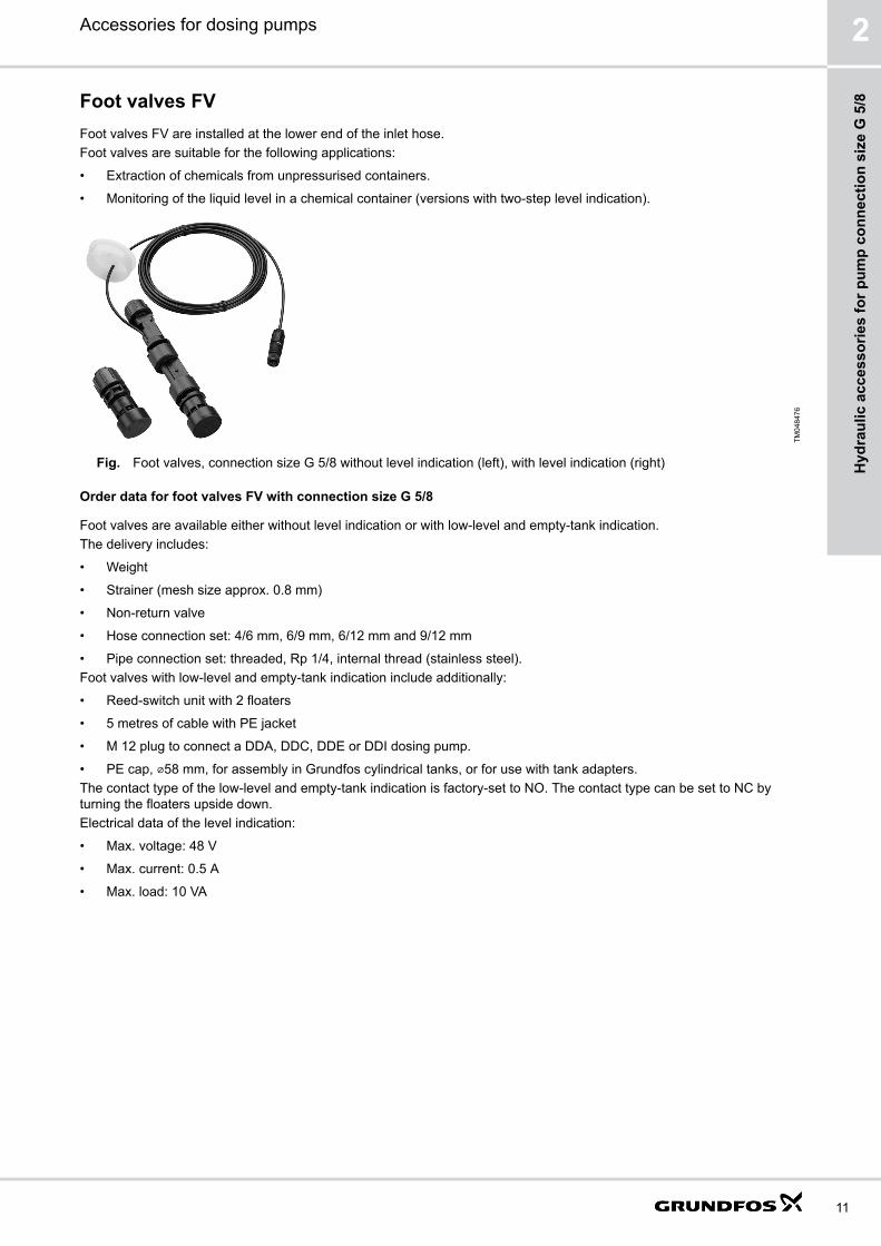
Foot valves FVFoot valves FV are installed at the lower end of the inlet hose.Foot valves are suitable for the following applications:
• Extraction of chemicals from unpressurised containers.
• Monitoring of the liquid level in a chemical container (versions with two-step level indication).
TM04
8476
Fig. Foot valves, connection size G 5/8 without level indication (left), with level indication (right)
Order data for foot valves FV with connection size G 5/8
Foot valves are available either without level indication or with low-level and empty-tank indication.The delivery includes:
• Weight
• Strainer (mesh size approx. 0.8 mm)
• Non-return valve
• Hose connection set: 4/6 mm, 6/9 mm, 6/12 mm and 9/12 mm
• Pipe connection set: threaded, Rp 1/4, internal thread (stainless steel).Foot valves with low-level and empty-tank indication include additionally:
• Reed-switch unit with 2 floaters
• 5 metres of cable with PE jacket
• M 12 plug to connect a DDA, DDC, DDE or DDI dosing pump.
• PE cap, ⌀58 mm, for assembly in Grundfos cylindrical tanks, or for use with tank adapters.The contact type of the low-level and empty-tank indication is factory-set to NO. The contact type can be set to NC byturning the floaters upside down.Electrical data of the level indication:
• Max. voltage: 48 V
• Max. current: 0.5 A
• Max. load: 10 VA
Accessories for dosing pumps 2
11
Hyd
raul
ic a
cces
sorie
s fo
r pum
p co
nnec
tion
size
G 5
/8

Dimensions
AI
Ø F
D
TM04
8446
Fig. Foot valve without level indication, PE / PVDF
AI
Ø F
D
TM04
8494
Fig. Foot valve without level indication (stainless-steelversion)
Body material A [mm] D ⌀F [mm] I [mm]
PE / PVDF 67.5 G 5/8 35 19
Stainless steel 30 G 5/8 30 4
A
G
I
DE
Ø F
H
D1
D2
D3
SS
S:S
TM04
8447
Fig. Foot valve with level indication
A [mm] D D1 / D2 / D3[mm]
E [mm] ⌀F [mm] G [mm] H [mm] I [mm]
196 G 5/8 12 / 9 / 6 58 35 103.5 43.5 19
Accessories for dosing pumps2
12
Hydraulic accessories for pum
p connection size G 5/8
Order dataThe flow rate values apply to liquids with a viscosity similar to water.
Max. flow rate [l/h] Material Product number
Body Gasket Ball FV without level indication FV with level indication
60 PE FKM, EPDM Ceramic 98070951 98070966
PTFE Ceramic 98070952 98070967
PVDF FKM, EPDM Ceramic 98070953 98070968
PTFE Ceramic 98070954 98070969
Stainless steel PTFE Stainless steel 98070963 -
Related informationFlat-plug adapter for DMX and DMH with AR control unit. See page 17.
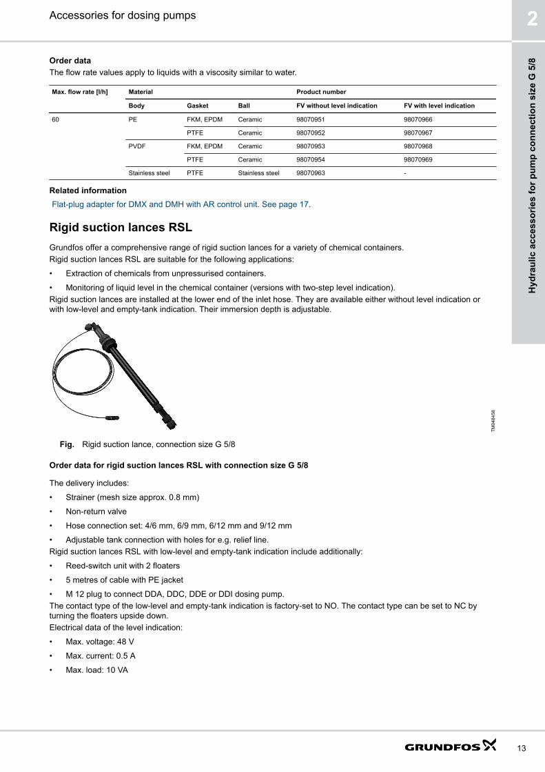
Rigid suction lances RSLGrundfos offer a comprehensive range of rigid suction lances for a variety of chemical containers.Rigid suction lances RSL are suitable for the following applications:
• Extraction of chemicals from unpressurised containers.
• Monitoring of liquid level in the chemical container (versions with two-step level indication).Rigid suction lances are installed at the lower end of the inlet hose. They are available either without level indication orwith low-level and empty-tank indication. Their immersion depth is adjustable.
TM04
8458
Fig. Rigid suction lance, connection size G 5/8
Order data for rigid suction lances RSL with connection size G 5/8
The delivery includes:
• Strainer (mesh size approx. 0.8 mm)
• Non-return valve
• Hose connection set: 4/6 mm, 6/9 mm, 6/12 mm and 9/12 mm
• Adjustable tank connection with holes for e.g. relief line.Rigid suction lances RSL with low-level and empty-tank indication include additionally:
• Reed-switch unit with 2 floaters
• 5 metres of cable with PE jacket
• M 12 plug to connect DDA, DDC, DDE or DDI dosing pump.The contact type of the low-level and empty-tank indication is factory-set to NO. The contact type can be set to NC byturning the floaters upside down.Electrical data of the level indication:
• Max. voltage: 48 V
• Max. current: 0.5 A
• Max. load: 10 VA
Accessories for dosing pumps 2
13
Hyd
raul
ic a
cces
sorie
s fo
r pum
p co
nnec
tion
size
G 5
/8

DimensionsA
B C
G
I
H
E
D
Ø F
TM04
8445
Fig. Rigid suction lance with / without level indication
A [mm] B [mm] C [mm] D E ⌀F [mm] G [mm] H [mm] I [mm]
400-1200 110 99 G 5/8 G 2 32 85 25 4.5
Selection
For container type Tank volume [l] Recommended immersion depth (L) [mm]
Grundfos cylindrical tank 40 400
60 500
100 690
200 690
300 980
500 1100
1000 1200
Grundfos square tank 100 690
L-ring drum 120 820
220 980
Steel drum 216 980
Standard jerricans according to EN 12712 12, 33 (large cap) 400
25, 30, 33 500
60 690
IBC all sizes 1200
Accessories for dosing pumps2
14
Hydraulic accessories for pum
p connection size G 5/8

Order dataThe flow rate values apply to liquids with a viscosity similar to water.Minimum immersion depth for all sizes: approx. 140 mm
Max. flow rate [l/h] Max. immersiondepth [mm]
Material Product number
Body Gasket Ball RSL without levelindication
RSL with levelindication
60 400 PE FKM, EPDM Ceramic 98070978 98071074
PTFE Ceramic 98070979 98071075
PVDF FKM, EPDM Ceramic 98070980 98071076
PTFE Ceramic 98070981 98071077
500 PE FKM, EPDM Ceramic 98070990 98071086
PTFE Ceramic 98070991 98071087
PVDF FKM, EPDM Ceramic 98070992 98071088
PTFE Ceramic 98070993 98071089
570 PE FKM, EPDM Ceramic 98071002 98071098
PTFE Ceramic 98071003 98071099
PVDF FKM, EPDM Ceramic 98071004 98071100
PTFE Ceramic 98071005 98071101
690 PE FKM, EPDM Ceramic 98071014 98071110
PTFE Ceramic 98071015 98071111
PVDF FKM, EPDM Ceramic 98071016 98071112
PTFE Ceramic 98071017 98071113
820 PE FKM, EPDM Ceramic 98071026 98071122
PTFE Ceramic 98071027 98071123
PVDF FKM, EPDM Ceramic 98071028 98071124
PTFE Ceramic 98071029 98071125
980 PE FKM, EPDM Ceramic 98071038 98071134
PTFE Ceramic 98071039 98071135
PVDF FKM, EPDM Ceramic 98071040 98071136
PTFE Ceramic 98071041 98071137
1100 PE FKM, EPDM Ceramic 98071050 98071146
PTFE Ceramic 98071051 98071147
PVDF FKM, EPDM Ceramic 98071052 98071148
PTFE Ceramic 98071053 98071149
1200 PE FKM, EPDM Ceramic 98071062 98071158
PTFE Ceramic 98071063 98071159
PVDF FKM, EPDM Ceramic 98071064 98071160
PTFE Ceramic 98071065 98071161
Accessories for dosing pumps 2
15
Hyd
raul
ic a
cces
sorie
s fo
r pum
p co
nnec
tion
size
G 5
/8

Accessories for rigid suction lances RSL and foot valves FV
Adapters for container connection
These adapters allow the installation of standard rigid suction lances RSL (G 2 thread) and foot valves FV with levelindication (PE cap) on different types of containers.
TM04
8506
Fig. Adapters for containers
Order dataType For container type Material Product number
TM04
8470 Counter nut for tanks without threaded opening, e.g. 100-litre
square tank or 1000-litre cylindrical tankPVC, grey 98071170
TM04
8471
Containers with 2 NPT threaded opening PVC, grey 98156690
Drums with S 70 x 6 coarse thread (MAUSER 2") PE, blue 98071171
Drums with S 56 x 4 coarse thread (TriSure®) PE, orange 98071172
TM04
8473
Jerricans with small opening (approx. ⌀36), according to EN12713
PE, green 98071173
TM04
8473
Jerricans with medium-sized opening (approx. ⌀45), according toEN 12713
PE, yellow 98071174
Jerricans with large opening (approx. ⌀57), according to EN12713
PE, brown 98071175
US containers with bung hole of 63 mm (ASTM International) PE, white 98071176
TM04
8472 IBC (Intermediate Bulk Container) with opening of ⌀150 mm, S
160 x 7PE, black 98071177
Emission protection kits for rigid suction lances RSL
Gas emitted by liquid in a container can cause bad odour and corrosion. Emission protection kits help avoid suchproblems. Rigid suction lances can be retrofitted with emission protection kits.Two variants are available:
• Emission protection kit with snifting valve: no gas can escape from the container, but air can be drawn in.
• Emission protection kit for use with filter: gas can escape from the container and air can be drawn in. The kit can beconnected to a filter by means of a 4/6 mm hose.
The delivery includes:
• Gasket for the tank adapter
• Snifting valve or hose nipple 4/6 mm (hose is not included)
• Gasket for the cable outlet.
Accessories for dosing pumps2
16
Hydraulic accessories for pum
p connection size G 5/8

1
2
3
TM06
9068
Fig. Emission protection kit
Pos. Description
1 Gasket for the cable outlet
2 Air valve
3 Gasket for the tank adapter
Order data
Variant Product number
Emission protection kit with snifting valve 98071178
Emission protection kit for use with filter 98071179
Flat-plug adapter for DMX and DMH with AR control unit
The flat-plug adapter allows to connect rigid suction lances or foot valves with level indication to pumps with a level inputdesigned for flat plugs (e.g. DMX and DMH with AR control unit).
TM07
0206
Fig. Flat-plug adapter for DMX and DMH with AR control unit
Order data
Description Product number
Flat-plug adapter for DMX and DMH with AR control unit 96635010
Accessories for dosing pumps 2
17
Hyd
raul
ic a
cces
sorie
s fo
r pum
p co
nnec
tion
size
G 5
/8
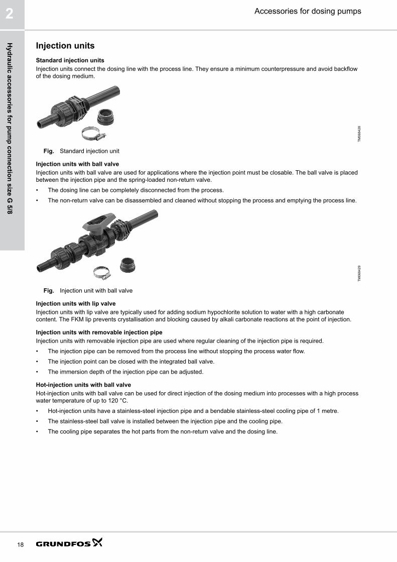
Injection unitsStandard injection unitsInjection units connect the dosing line with the process line. They ensure a minimum counterpressure and avoid backflowof the dosing medium.
TM06
8428
Fig. Standard injection unit
Injection units with ball valveInjection units with ball valve are used for applications where the injection point must be closable. The ball valve is placedbetween the injection pipe and the spring-loaded non-return valve.
• The dosing line can be completely disconnected from the process.
• The non-return valve can be disassembled and cleaned without stopping the process and emptying the process line.
TM06
8429
Fig. Injection unit with ball valve
Injection units with lip valveInjection units with lip valve are typically used for adding sodium hypochlorite solution to water with a high carbonatecontent. The FKM lip prevents crystallisation and blocking caused by alkali carbonate reactions at the point of injection.
Injection units with removable injection pipeInjection units with removable injection pipe are used where regular cleaning of the injection pipe is required.
• The injection pipe can be removed from the process line without stopping the process water flow.
• The injection point can be closed with the integrated ball valve.
• The immersion depth of the injection pipe can be adjusted.
Hot-injection units with ball valveHot-injection units with ball valve can be used for direct injection of the dosing medium into processes with a high processwater temperature of up to 120 °C.
• Hot-injection units have a stainless-steel injection pipe and a bendable stainless-steel cooling pipe of 1 metre.
• The stainless-steel ball valve is installed between the injection pipe and the cooling pipe.
• The cooling pipe separates the hot parts from the non-return valve and the dosing line.
Accessories for dosing pumps2
18
Hydraulic accessories for pum
p connection size G 5/8

Order data for injection units for pump connection size G 5/8
Injection units for small dosing pumps with G 5/8 connections ensure a minimum counterpressure of 0.7 bar.The delivery includes:
• Injection pipe
• PP, PVC and PVDF versions can be shortened
• Spring-loaded non-return valve with Tantalum spring
• Hose connection set (PP, PVC, PVDF): 4/6 mm, 6/9 mm, 6/12 mm, 9/12 mm
• Pipe connection set (Stainless steel): threaded, Rp 1/4, internal thread
Dimensions of standard injection units
A
L2 L1
TM06
9845
Fig. Body material: PP, PVC, PVDF
A
L1L2
TM06
9846
Fig. Body material: Stainless steel
Material A L1 [mm] L2 [mm]
PVC G 1/2 100 / 300 47
PP, PVDF G 1/2 100 47
Stainless steel G 1/2 27 50
Order data for standard injection units• Max. flow rate: 60 l/h
• The flow rate values apply to liquids with a viscosity similar to water.
Max. pressure [bar] L1 [mm] Material Product number
Body Gasket Ball
16 100 PVC FKM Ceramic 95730912
EPDM Ceramic 95730916
PTFE Ceramic 95730920
PP FKM Ceramic 95730904
EPDM Ceramic 95730908
PVDF FKM Ceramic 95730924
EPDM Ceramic 95730928
PTFE Ceramic 95730932
16 300 PVC FKM Ceramic 95730940
EPDM Ceramic 95730944
PTFE Ceramic 95730948
100 27 Stainless steel PTFE Stainless steel 95730936
Dimensions of injection units with lip valve
A
L1L2
TM06
9847
A L1 [mm] L2 [mm]
G 1/2 55 59
Accessories for dosing pumps 2
19
Hyd
raul
ic a
cces
sorie
s fo
r pum
p co
nnec
tion
size
G 5
/8

Order data for injection units with lip valve• Max. flow rate: 60 l/h
• Max. pressure: 16 bar
• The flow rate values apply to liquids with a viscosity similar to water.
Material Product number
Body Gasket Ball
PVC FKM Ceramic 95730964
Dimensions of injection units with ball valve
L1L2
A
TM06
9848
Material A L1 [mm] L2 [mm]
PVC G 1/2 100 183
Stainless steel G 1/2 27 138
Order data for injection units with ball valve• Max. flow rate: 60 l/h
• The flow rate values apply to liquids with a viscosity similar to water.
Max. pressure [bar] Material Product number
Body Gasket Ball
16 PVC FKM Ceramic 95730952
EPDM Ceramic 95730956
64 Stainless steel PTFE Stainless steel 95730960
Dimensions of injection units with removable injection pipe
L1
A
L2
TM06
9849
A L1 [mm] L2 [mm]
G 1/2 185 280
Order data for injection units with removable injection pipe• Max. flow rate: 60 l/h
• Max. pressure: 10 bar
• The flow rate values apply to liquids with a viscosity similar to water.
Material Product number
Body Gasket Ball
PVC FKM Ceramic 95730968
EPDM Ceramic 95730972
Accessories for dosing pumps2
20
Hydraulic accessories for pum
p connection size G 5/8

Dimensions of hot-injection units with ball valve
L1L2
A
TM06
9850
A L1 [mm] L2 [mm]
G 1/2 27 1158
Order data for hot-injection units with ball valve• Max. flow rate: 60 l/h
• Maximum process water temperature: 120 °C
• The flow rate values apply to liquids with a viscosity similar to water.
Max. pressure [bar] Material Product number
Body Gasket Ball
16 PVDF PTFE Ceramic 95730976
64 Stainless steel PTFE Stainless steel 95730980
Multi-function valves, pressure relief valves, pressure loading valves
Multi-function valves MFV
Multi-function valves MFV combine the functions of pressure relief valves PRV and pressure loading valves PLV.
• Pressure relief valves PRV protect the pump and the outlet-side installations against excessive pressure.
• Pressure loading valves PLV maintain a certain counterpressure for the dosing pump.In addition, multi-function valves allow deaeration of the pump and emptying of the outlet line for maintenance.A multi-function valve is mounted directly on the pump outlet side. The top connection is for the outlet line, the sideconnection leads the relief liquid back into the tank.
TM04
1224
Fig. Multi-function valve MFV
Accessories for dosing pumps 2
21
Hyd
raul
ic a
cces
sorie
s fo
r pum
p co
nnec
tion
size
G 5
/8

Order data for multi-function valves MFV
• Loading pressure:
• factory-set to 3 bar approximately
• adjustable from 1 to 4 bar
• Relief pressure:
• factory-set to 10 bar or 16 bar approximately
• adjustable from 7 to 16 bar
• Max. operating pressure: 16 bar
• Max. flow rate: 60 l/h
• The flow rate values apply to liquids with a viscosity similar to water.
• Body material: PVDF
• Connection size: 5/8
• Hose connection set: 4/6 mm, 6/9 mm, 6/12 mm, 9/12 mm
Dimensions
H1
L1
H3
H2
L2G
Ø D
TM06
9769
Fig. Multi-function valve MFV
L1 [mm] L2 [mm] H1 [mm] H2 [mm] H3 [mm] ⌀ D [mm] G
139 45 92 47 45 60 G 5/8
Order data
Material Product number
Connections Gaskets Diaphragm Relief pressure: 10 bar Relief pressure: 16 bar
PP FKM PTFE 95704585 95730821
EPDM PTFE 95704591 95730822
PVC FKM PTFE 95730807 95730823
EPDM PTFE 95730808 95730824
PTFE PTFE 95730809 95730825
PVDF FKM PTFE 95730810 95730826
EPDM PTFE 95730811 95730827
PTFE PTFE 95730812 95730828
Accessories for dosing pumps2
22
Hydraulic accessories for pum
p connection size G 5/8

Pressure relief valves PRV
Pressure relief valves PRV protect the pump and the outlet-side installations against excessive pressure. All pressuriseddosing installations should include a pressure relief valve.
TM06
9784
Fig. Pressure relief valve PRV, G 5/8
Order data for pressure relief valves PRV for pump connection size G 5/8
Pressure relief valves PRV for small dosing pumps with G 5/8 connections are installed in the outlet line near the pumpusing the 2 in-line connections. The side connection leads the relief liquid back into the tank.
• Relief pressure:
• factory-set to 10 bar approximately, adjustable from 5 to 10 bar
• factory-set to 16 bar approximately, adjustable from 7 to 16 bar
• Max. operating pressure: 16 bar
• Max. flow rate: 60 l/h
• The flow rate values apply to liquids with a viscosity similar to water.
• Hose connection set: 4/6 mm, 6/9 mm, 6/12 mm, 9/12 mm
• Pipe connection set (Stainless steel): threaded, Rp 1/4, internal thread
• Diaphragm: PTFE-coated
Dimensions
ØD2
L3
H1
D1
L2
L1
H2
TM06
9786
Fig. Pressure relief valve PRV
Material L1 [mm] L2 [mm] L3 [mm] H1 [mm] H2 [mm] D1 [mm] ⌀ D2 [mm]
PP / PVC / PVDF 82 21 48 96 68 78 4.5
Stainless steel 82 22 20 40 68 - -
Order data
Material Product number
Diaphragm Body / Connections Gaskets Relief pressure: 10 bar Relief pressure: 16 bar
PTFE PP FKM / EPDM 95730757 95730773
PVC FKM / EPDM 95730758 95730774
PTFE 95730759 95730775
PVDF FKM / EPDM 95730760 95730776
PTFE 95730761 95730777
Stainless steel - 95730771 95730783
Accessories for dosing pumps 2
23
Hyd
raul
ic a
cces
sorie
s fo
r pum
p co
nnec
tion
size
G 5
/8
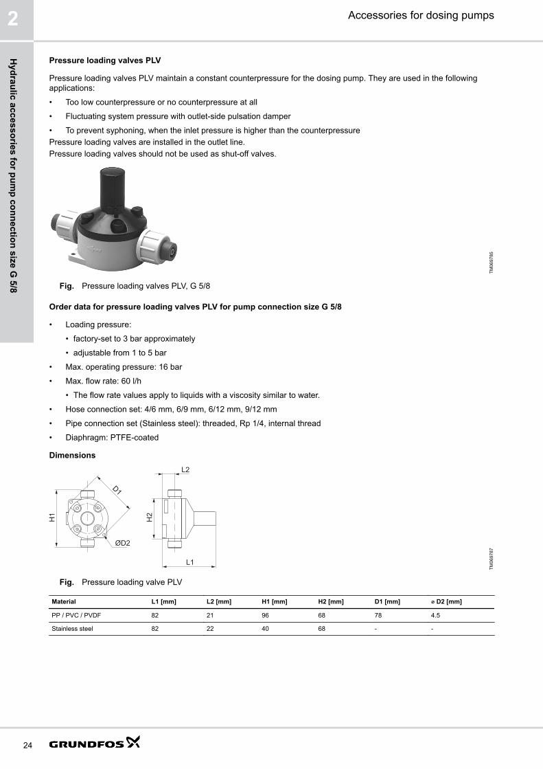
Pressure loading valves PLV
Pressure loading valves PLV maintain a constant counterpressure for the dosing pump. They are used in the followingapplications:
• Too low counterpressure or no counterpressure at all
• Fluctuating system pressure with outlet-side pulsation damper
• To prevent syphoning, when the inlet pressure is higher than the counterpressurePressure loading valves are installed in the outlet line.Pressure loading valves should not be used as shut-off valves.
TM06
9785
Fig. Pressure loading valves PLV, G 5/8
Order data for pressure loading valves PLV for pump connection size G 5/8
• Loading pressure:
• factory-set to 3 bar approximately
• adjustable from 1 to 5 bar
• Max. operating pressure: 16 bar
• Max. flow rate: 60 l/h
• The flow rate values apply to liquids with a viscosity similar to water.
• Hose connection set: 4/6 mm, 6/9 mm, 6/12 mm, 9/12 mm
• Pipe connection set (Stainless steel): threaded, Rp 1/4, internal thread
• Diaphragm: PTFE-coated
DimensionsL2
H2
L1
ØD2
D1
H1
TM06
9787
Fig. Pressure loading valve PLV
Material L1 [mm] L2 [mm] H1 [mm] H2 [mm] D1 [mm] ⌀ D2 [mm]
PP / PVC / PVDF 82 21 96 68 78 4.5
Stainless steel 82 22 40 68 - -
Accessories for dosing pumps2
24
Hydraulic accessories for pum
p connection size G 5/8

Order data
Material Product number
Diaphragm Body and connections Gaskets
PTFE PP FKM / EPDM 95730741
PVC FKM / EPDM 95730742
PTFE 95730743
PVDF FKM / EPDM 95730744
PTFE 95730745
Stainless steel - 95730751
Pressure valves PV
Pressure valves PV provide a constant counterpressure of 3 bar.They are particularly required for SMART Digital S DDA-FC or DDA-FCM pumps at very small flow rates.Pressure valves are installed either directly on the pump outlet valve, or on the pressure relief valve.
Order data for pressure valves PV for pump connection size G 5/8
• Loading pressure: 3 bar, not adjustable
• Max. operating pressure: 16 bar
• Max. flow rate: 60 l/h (The flow rate values apply to liquids with a viscosity similar to water.)
• Spring material: Tantalum alloy
• No connections included
A
BTM
0697
96
Fig. Dimensions of pressure valve PV
A [mm] B
87 G 5/8
Material Product number
Body Ball Gaskets
PP Ceramic FKM 95730325
EPDM 95730326
PVC Ceramic FKM 95730327
EPDM 95730328
PTFE 95730329
PVDF Ceramic FKM 95730330
EPDM 95730331
PTFE 95730332
Stainless steel Stainless steel PTFE 95730333
Accessories for dosing pumps 2
25
Hyd
raul
ic a
cces
sorie
s fo
r pum
p co
nnec
tion
size
G 5
/8

Pulsation dampers and calibration columns
Discharge-side pulsation dampers DB and DBGPulsation dampers are used to even out the pulsating flow and pressure produced by positive displacement pumps likediaphragm dosing pumps.Pulsation dampers DB and DBG have a separating diaphragm and are intended for the outlet side of the dosing pump.They are especially designed for installations with long outlet lines with a small diameter, or with rigid pipes. The pulsationdampers optimise the dosing accuracy and protect the pump and the outlet line against pressure surges.Pulsation dampers DB and DBG have an air or nitrogen cushion inside, which is separated from the dosing medium by aseparating diaphragm. This keeps the preload pressure stable for a long time and avoids that air or nitrogen is dissolved inthe dosing medium.In PVC, PP, and stainless steel pulsation dampers, an FKM or EPDM bladder is used as separating diaphragm, in PVDFpulsation dampers a PTFE bellows is used as separating diaphragm.Pulsation dampers DBG include a pressure gauge for easy setting of the correct pressure. Pulsation dampers DB have nopressure gauge.Grundfos SMART Digital dosing pumps do not require a DB or DBG pulsation damper, if the flow rate is limited to 75 % ofthe maximum dosing capacity of the pump. In rigid pipe installations, the flow rate without pulsation damper should notexceed 50 % of the maximum dosing capacity of the pump.If the counterpressure in the system is low or fluctuating, the installation of a pressure loading valve PLV after thepulsation damper may be required to optimise its function.
TM06
8424
Fig. Discharge-side pulsation damper DBG
Accessories for dosing pumps2
26
Hydraulic accessories for pum
p connection size G 5/8

Suction-side pulsation dampers CSD with calibration scale
Pulsation dampers are used to even out the pulsating flow and pressure produced by positive displacement pumps likediaphragm dosing pumps.Pulsation dampers CSD are installed on the inlet side of the dosing pump. They can be used for multiple pumps that aresupplied by the same inlet line.Pulsation dampers CSD help to ensure the accuracy of dosing pumps, which is highly dependent on proper suctionconditions. In installations with long inlet lines or inlet lines with a small diameter, the use of a CSD pulsation damper isrecommended.Pulsation dampers CSD have a transparent PVC cylinder with a fine volume scale. When combined with a shut-off valvein the inlet line, they can also be used for calibration or flow measurement. In installations without flooded suction, theoptional manual vacuum pump kit simplifies startup of the dosing pump.
TM06
8450
Fig. Suction-side pulsation dampers CSD with calibration scale
Calibration columns
Calibration columns have a graduated glass cylinder with a fine scale. A shut-off valve on the lower end can disconnectthem from the inlet-side installation during normal operation.One calibration column can be used for multiple pumps that are supplied by the same inlet line.Calibration columns must not be used as pulsation dampers.
Accessories for dosing pumps 2
27
Hyd
raul
ic a
cces
sorie
s fo
r pum
p co
nnec
tion
size
G 5
/8

Sizing guide for pulsation dampers and calibration columns, pump connection size G 5/8
Look up your pump type in the table. Find the required pulsation damper or calibration column volume in the respectivetable column.
Pump type Pump stroke volume [ml] Required volume [l]
DB / DBG CSD Calibration column
DDC-DDE 6-10 0.81 0.15 - 0.18 0.25 0.25
DDA 7.5-16* 0.74
DDC 9-7 0.84
DDA 12-10 1.45
DDC-DDE 15-4 1.58
DDA 17-7 1.55
DDA 30-4* 3.1
DDI 60-10 6.67 0.15 - 0.18 0.5 0.5
DMX 4-10 2.2 0.15 - 0.18 0.5 0.5
DMX 8-10
DMX 16-10
DMX 16-12 2.2 0.15 - 0.18 0.5 0.5
DMX 7-10 3.8 0.15 - 0.18 0.5 0.5
DMX 14-10
DMX 27-10
DMX 27-12 3.8 0.15 - 0.18 0.5 0.5
DMX 9-10 4.9 0.15 - 0.18 0.5 0.5
DMX 18-10
DMX 35-10
DMX 12-10 6.9
DMX 26-10
DMX 50-10
DMH 5-10 3.5 0.15 - 0.18 0.5 0.5
DMH 13-10
DMH 24-10
DMH 11-10 6.4
DMH 24-10
DMH 46-10
* For very low residual pulsation, a larger damper should be used.
Order data for pulsation dampers CSD, pump connection size G 5/8
Features• Prepared for pipe gluing connection with spigot (D) or socket (d).
• Calibration is possible by installing a T-piece and a shut-off valve.
• In installations without flooded suction, the optional manual vacuum pump kit simplifies the startup of the dosingpump.
The delivery includes:
• Sight glass with calibration scale
• Aeration valve
• Material for wall mounting
Accessories for dosing pumps2
28
Hydraulic accessories for pum
p connection size G 5/8
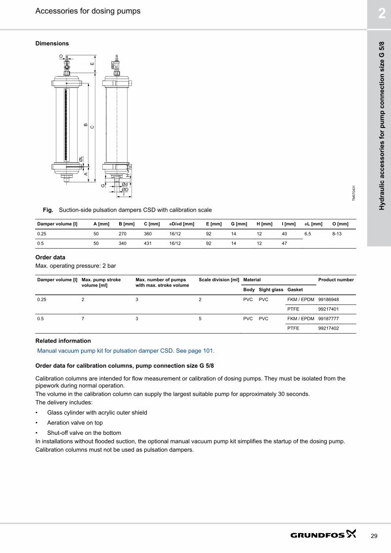
Dimensions
IØDØdG
HAB C
E
ØL
O
TM07
0431
Fig. Suction-side pulsation dampers CSD with calibration scale
Damper volume [l] A [mm] B [mm] C [mm] ⌀D/⌀d [mm] E [mm] G [mm] H [mm] I [mm] ⌀L [mm] O [mm]
0.25 50 270 360 16/12 92 14 12 40 6.5 8-13
0.5 50 340 431 16/12 92 14 12 47
Order dataMax. operating pressure: 2 bar
Damper volume [l] Max. pump strokevolume [ml]
Max. number of pumpswith max. stroke volume
Scale division [ml] Material Product number
Body Sight glass Gasket
0.25 2 3 2 PVC PVC FKM / EPDM 99186948
PTFE 99217401
0.5 7 3 5 PVC PVC FKM / EPDM 99187777
PTFE 99217402
Related informationManual vacuum pump kit for pulsation damper CSD. See page 101.
Order data for calibration columns, pump connection size G 5/8
Calibration columns are intended for flow measurement or calibration of dosing pumps. They must be isolated from thepipework during normal operation.The volume in the calibration column can supply the largest suitable pump for approximately 30 seconds.The delivery includes:
• Glass cylinder with acrylic outer shield
• Aeration valve on top
• Shut-off valve on the bottomIn installations without flooded suction, the optional manual vacuum pump kit simplifies the startup of the dosing pump.Calibration columns must not be used as pulsation dampers.
Accessories for dosing pumps 2
29
Hyd
raul
ic a
cces
sorie
s fo
r pum
p co
nnec
tion
size
G 5
/8

Dimensions
Ød
AB
ØD
ØCHH
EØF
TM06
8405
Fig. Calibration column
Volume [l] Body A [mm] B [mm] ⌀C [mm] ⌀D [mm] E ⌀F [mm] H [mm]
0.25 PVDF 478 184 12 50.8 M 10 12 50-154
SS 460 140
0.5 PVDF 517 184 12 69.85 M 10 12 61-165
SS 498 140
Order data
Volume [l] Max. pump stroke volume [ml] Scale division [ml] Connection ⌀d Material Product number
[mm] Body Gasket
0.25 2 2 16 - PVDF FKM 99224280
- G 1/2 SS FKM 99224303
SS EPDM 99224304
0.5 7 5 16 - PVDF FKM 99224305
- G 1/2 SS FKM 99224307
SS EPDM 99224308
Related informationManual vacuum pump kit for calibration columns. See page 102.
Order data for pulsation dampers DB and DBG, pump connection size G 5/8
We recommend using one pulsation damper per dosing pump.Preload pressure: 2.7 bar.The delivery includes::
• Material for wall mounting
• PVC versions are prepared for pipe gluing connection with spigot (D) or socket (d).
• PVDF and PP versions are prepared for pipe welding connection with spigot (D) or socket (d).
• Pulsation dampers DBG include a pressure gauge.
Accessories for dosing pumps2
30
Hydraulic accessories for pum
p connection size G 5/8
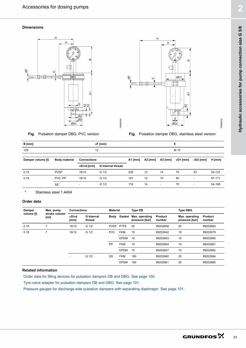
Dimensions
A2
A3
A1
B
H
H
EØF
ØD1ØD
G
ØdTM
0682
84
Fig. Pulsation damper DBG, PVC version
ØD2
G
A2
A1
ØD1
HH
EØF
B
TM06
8452
Fig. Pulsation damper DBG, stainless steel version
B [mm] ⌀F [mm] E
129 12 M 10
Damper volume [l] Body material Connections A1 [mm] A2 [mm] A3 [mm] ⌀D1 [mm] ⌀D2 [mm] H [mm]
⌀D/⌀d [mm] G Internal thread
0.15 PVDF 16/12 G 1/2 205 12 14 70 53 53-127
0.18 PVC, PP 16/12 G 1/2 161 12 14 80 - 67-171
SS* - G 1/2 118 14 - 70 - 64-168
* Stainless steel 1.4404
Order data
Dampervolume [l]
Max. pumpstroke volume[ml]
Connections Material Type DB Type DBG
⌀D/⌀d[mm]
G Internalthread
Body Gasket Max. operatingpressure [bar]
Productnumber
Max. operatingpressure [bar]
Productnumber
0.15 7 16/12 G 1/2 PVDF PTFE 20 99202658 20 99202683
0.18 7 16/12 G 1/2 PVC FKM 10 99202642 10 99202679
EPDM 10 99202653 10 99202680
PP FKM 10 99202654 10 99202681
EPDM 10 99202657 10 99202682
- G 1/2 SS FKM 180 99202660 25 99202684
EPDM 180 99202661 25 99202685
Related informationOrder data for filling devices for pulsation dampers DB and DBG. See page 100.
Tyre-valve adapter for pulsation dampers DB and DBG. See page 101.
Pressure gauges for discharge-side pulsation dampers with separating diaphragm. See page 101.
Accessories for dosing pumps 2
31
Hyd
raul
ic a
cces
sorie
s fo
r pum
p co
nnec
tion
size
G 5
/8

Accessories for hydraulic connection
Pump connection kits and inlay kits for pump connection size G 5/8
Retrofit pump connection kits and inlay kits for the integration of Grundfos standard dosing pumps into installations withvarious sizes of hoses or pipes.A pump connection kit includes one set of inlays and one union nut.
TM04
8294
Fig. Pump connection kitThe inlay kits are used to connect pumps and accessories to pipes or hoses that differ from Grundfos standard sizes.An inlay kit includes two sets of inlays.
TM04
8295
Fig. Inlay kit
Order data
Connection type Size Material Product number
Connection kit Inlay kit
Hose (cone and ring) 4/6 mm, 6/9 mm, 6/12 mm, 9/12 mm PP 97691902 -
PVC 97691903 -
PVDF 97691904 -
0.17" x 1/4", 1/4" x 3/8", 3/8" x 1/2" PP 97691905 -
PVC 97691906 -
PVDF 97691907 -
Hose (cone and ring)Hose (cone and ring) 4/6 mm, or 0.17" x 1/4" PP 97702474 95730984
PVC 97702485 95730720
PVDF 97702495 95730729
4/9 mm PP 98153922 98153977
PVC 98153944 98154006
PVDF 98153949 98154029
Hose (cone and ring) 5/8 mm PP 97702475 95730711
PVC 97702486 95730721
PVDF 97702496 95730730
Accessories for dosing pumps2
32
Hydraulic accessories for pum
p connection size G 5/8

Connection type Size Material Product number
Connection kit Inlay kit
Hose (cone and ring) 6/8 mm PP 97702476 95730712
PVC 97702487 95730722
PVDF 97702497 95730731
6/9 mm PP 97702477 95730713
PVC 97702488 95730723
PVDF 97702498 95730732
6/12 mm PP 97702478 95730714
PVC 97702489 95730724
PVDF 97702499 95730733
Hose (cone and ring) 9/12 mm PP 97702479 95730715
PVC 97702490 95730725
PVDF 97702500 95730734
Hose (cone and ring) 1/4" x 3/8" PP 97702482 95730718
PVC 97702492 95730727
PVDF 97702503 95730737
3/8" x 1/2" PP 97702483 95730719
PVC 97702493 95730728
PVDF 97702504 95730738
Hose (cutting ring type) 1/8" x 1/4" PP 97702481 95730717
PVDF 97702502 95730736
Pipe welding External diameter 16 mm PP 97702480 95730716
PVDF 97702501 95730735
DN 10, 3/8" Stainless steel 99369683 -
Pipe cementing Internal diameter 12 mm PVC 97702491 95730726
Pipe, external thread 1/2 NPT PP 97702484 -
PVC 97702494 -
PVDF 97702505 -
Stainless steel 97702508 -
Pipe, internal thread Rp 1/4 Stainless steel 97702472 95730739
1/4 NPT Stainless steel 97702473 95730740
Pipe (cutting ring type) 4/6 mm Stainless steel 97702506 -
8/10 mm Stainless steel 97702507 -
10/12 mm Stainless steel 98807664 -
Threaded adapters G 5/8
With threaded adapters, different sizes of threaded connections can be connected. A threaded adapter includes a gasket.
Technical dataType Threaded connection size Material Product number
Internal thread External thread Body Gaskets
TM04
8297
G 5/8 G 3/8 PP FKM / EPDM 95730412
PVC FKM / EPDM 95730413
PTFE 95730414
PVDF FKM / EPDM 95730415
PTFE 95730416
Accessories for dosing pumps 2
33
Hyd
raul
ic a
cces
sorie
s fo
r pum
p co
nnec
tion
size
G 5
/8
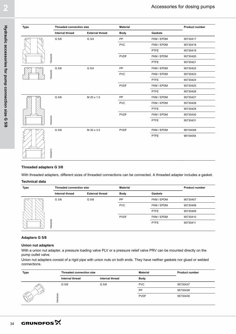
Type Threaded connection size Material Product number
Internal thread External thread Body Gaskets
TM04
8298
G 5/8 G 3/4 PP FKM / EPDM 95730417
PVC FKM / EPDM 95730418
PTFE 95730419
PVDF FKM / EPDM 95730420
PTFE 95730421
TM04
8299
G 5/8 G 5/4 PP FKM / EPDM 95730422
PVC FKM / EPDM 95730423
PTFE 95730424
PVDF FKM / EPDM 95730425
PTFE 95730426
TM04
8300
G 5/8 M 20 x 1.5 PP FKM / EPDM 95730427
PVC FKM / EPDM 95730428
PTFE 95730429
PVDF FKM / EPDM 95730430
PTFE 95730431
TM04
8475
G 5/8 M 30 x 3.5 PVDF FKM / EPDM 98154048
PTFE 98154054
Threaded adapters G 3/8
With threaded adapters, different sizes of threaded connections can be connected. A threaded adapter includes a gasket.
Technical dataType Threaded connection size Material Product number
Internal thread External thread Body Gaskets
TM04
8296
G 3/8 G 5/8 PP FKM / EPDM 95730407
PVC FKM / EPDM 95730408
PTFE 95730409
PVDF FKM / EPDM 95730410
PTFE 95730411
Adapters G 5/8
Union nut adaptersWith a union nut adapter, a pressure loading valve PLV or a pressure relief valve PRV can be mounted directly on thepump outlet valve.Union nut adapters consist of a rigid pipe with union nuts on both ends. They have neither gaskets nor glued or weldedconnections.
Type Threaded connection size Material Product number
Internal thread Internal thread Body
TM04
8306
G 5/8 G 5/8 PVC 95730437
PP 95730438
PVDF 95730439
Accessories for dosing pumps2
34
Hydraulic accessories for pum
p connection size G 5/8

Hose-to-hose and hose-to-pipe adaptersWith these adapters, hoses or pipes of different sizes can be connected. The threaded adapter side includes a gasket.Connections for different hose types can be included.
Adapters with two external threads G 5/8
Type Connections Material Product number
Side 1 Side 2 Body and connections Gaskets
TM04
8302
External threads G 5/8, connections for hoses 4/6mm, 6/9 mm, 6/12 mm, 9/12 mm
PP FKM / EPDM 95730367
PVC FKM / EPDM 95730368
PTFE 95730369
PVDF FKM / EPDM 95730370
PTFE 95730371
External threads G 5/8, without connections PP FKM / EPDM 95730356
PVC FKM / EPDM 95730357
PTFE 95730358
PVDF FKM / EPDM 95730359
PTFE 95730360
External thread G 5/8,without connection
External thread G 5/8,with threaded Rp 1/4connection
Stainless steel PTFE 95730361
Adapters with pipe cementing end and external thread G 5/8
Type Connections Material Product number
Side 1 Side 2 Body and connections Gaskets
TM04
8360
External threads G 5/8,connections for hoses4/6 mm, 6/9 mm, 6/12mm, 9/12 mm
Pipe cementing endwith internal ⌀12 mm
PVC FKM / EPDM 95730378
PTFE 95730379
External thread G 5/8,without connection
Pipe cementing endwith internal ⌀12 mm
PVC FKM / EPDM 95730365
PTFE 95730366
Adapters with pipe welding end and external thread G 5/8
Type Connections Material Product number
Side 1 Side 2 Body and connections Gaskets
TM04
8303
External threads G 5/8,connections for hoses4/6 mm, 6/9 mm, 6/12mm, 9/12 mm
Pipe welding end withexternal ⌀16 mm
PP FKM / EPDM 95730377
PVDF FKM / EPDM 95730380
PTFE 95730381
External thread G 5/8,without connection
Pipe welding end withexternal ⌀16 mm
PP FKM / EPDM 95730362
PVDF FKM / EPDM 95730363
PTFE 95730364
Accessories for dosing pumps 2
35
Hyd
raul
ic a
cces
sorie
s fo
r pum
p co
nnec
tion
size
G 5
/8

T-piece adapters G 5/8
T-piece adapters can connect three lines. T-piece adapters include gaskets.Connections for different hose types can be included.
T-piece adapters with three external threads G 5/8
Type Connections Material Product number
Bottom Top Side Body andconnections
Gaskets
TM04
8304
External thread G 5/8, connections for hoses 4/6 mm,6/9 mm, 6/12 mm, 9/12 mm
PP FKM / EPDM 95730387
PVC FKM / EPDM 95730388
PTFE 95730389
PVDF FKM / EPDM 95730390
PTFE 95730391
External thread G 5/8, without connection PP FKM / EPDM 95730346
PVC FKM / EPDM 95730347
PTFE 95730348
PVDF FKM / EPDM 95730349
PTFE 95730350
T-piece adapters with internal connection with union nut and two external threads G 5/8
Type Connections Material Product number
Bottom Top Side Body andconnections
Gaskets
TM04
8305
Internalconnection, withunion nut G 5/8
External threadG 5/8, withoutconnection
External threadG 5/8,connections forhoses 4/6 mm,6/9 mm, 6/12mm, 9/12 mm
PP FKM / EPDM 95730397
PVC FKM / EPDM 95730398
PTFE 95730399
PVDF FKM / EPDM 95730400
PTFE 95730401
External threadG 5/8, withoutconnection
PP FKM / EPDM 95730351
PVC FKM / EPDM 95730352
PTFE 95730353
PVDF FKM / EPDM 95730354
PTFE 95730355
Accessories for dosing pumps2
36
Hydraulic accessories for pum
p connection size G 5/8
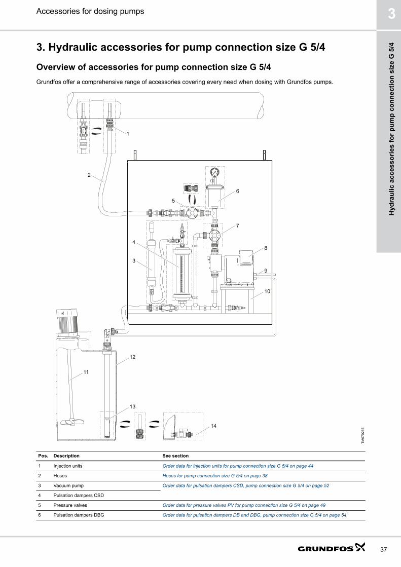
3. Hydraulic accessories for pump connection size G 5/4
Overview of accessories for pump connection size G 5/4Grundfos offer a comprehensive range of accessories covering every need when dosing with Grundfos pumps.
1
2
6
5
7
9
10
13
3
11
12
84
14
TM07
0285
Pos. Description See section
1 Injection units Order data for injection units for pump connection size G 5/4 on page 44
2 Hoses Hoses for pump connection size G 5/4 on page 38
3 Vacuum pump Order data for pulsation dampers CSD, pump connection size G 5/4 on page 52
4 Pulsation dampers CSD
5 Pressure valves Order data for pressure valves PV for pump connection size G 5/4 on page 49
6 Pulsation dampers DBG Order data for pulsation dampers DB and DBG, pump connection size G 5/4 on page 54
Accessories for dosing pumps 3
37
Hyd
raul
ic a
cces
sorie
s fo
r pum
p co
nnec
tion
size
G 5
/4

Pos. Description See section
7 Pressure relief valves, pressure loading valves Order data for pressure relief valves PRV for pump connection size G 5/4 on page 46Order data for pressure loading valves PLV for pump connection size G 5/4 on page 48
8 Example: SMART Digital XL dosing pump
9 Cables and plugs Cables and plugs for pump connection size G 5/4 on page 105
10 Wall brackets Pump mounting accessories on page 99
11 Electrical stirrers Electric stirrers on page 94
12 Dosing tanks Square tank on page 85Cylindrical tanks on page 86
13 Rigid suction lances and foot valves Order data for rigid suction lances RSL with connection size G 5/4 on page 40Order data for foot valves FV with connection size G 5/4 on page 39
14 Withdrawal devices Tank accessories on page 92
- Accessories for hydraulic connection Pump connection kits and inlay kits for pump connection size G 5/4 on page 56Threaded adapters G 5/4 on page 57Adapters G 5/4 on page 58Preassembled accessories set for SMART Digital XL on page 58
Hoses for pump connection size G 5/4Hoses in various materials, sizes and lengths for dosing pumps.Pump connection size: G 5/4
TM01
8958
Fig. Hoses
Order dataThe flow rate values apply to liquids with a viscosity similar to water.
Max. flow rate [l/h] Size (internal/externaldiameter) [mm]
Material Max. pressure at 20 °C[bar]
Length [m] Product number
200 13/20 PVC, textile-reinforced 15 3 96727423
10 96727420
50 96692592
460 19/27 PVC, textile-reinforced 12 3 96727426
10 96696200
50 96695788
19/24.6 PVC, reinforced with aplastic spiral
7 3 99168771
Accessories for dosing pumps3
38
Hydraulic accessories for pum
p connection size G 5/4

Foot valves FVFoot valves FV are installed at the lower end of the inlet hose.Foot valves are suitable for the following applications:
• Extraction of chemicals from unpressurised containers.
TM06
8427
Fig. Foot valve, connection size G 5/4
Order data for foot valves FV with connection size G 5/4
Foot vales G 5/4 have no level indication.The delivery includes:
• Strainer (mesh size approx. 0.8 mm)
• Non-return valve
• Hose and pipe connection set:
• for hoses with internal diameter 19 or 20 mm
• for pipes with external diameter 25 mm (PE includes PVC inlay, PVDF includes PVDF inlay)
• Pipe connection set: threaded, Rp 3/4, internal thread (stainless steel).Remark: When using the foot valves with hose installation, a rigid pipe should be slipped over the hose to keep the suctionline straight and upright in the tank.
Dimensions
L
d
L
d
TM06
9058
Fig. Left: Foot valve FV (PE, PVDF). Right: Foot valve FV (stainless steel)
Material d [mm] L [mm]
PE, PVDF 53 57
SS 50 57
Accessories for dosing pumps 3
39
Hyd
raul
ic a
cces
sorie
s fo
r pum
p co
nnec
tion
size
G 5
/4

Order dataThe flow rate values apply to liquids with a viscosity similar to water.
Max. flow rate [l/h] Material Product number
Body Gasket Ball
460 PE FKM / EPDM Ceramic 99168633
PTFE Ceramic 99168635
PVDF FKM / EPDM Ceramic 99168636
PTFE Ceramic 99168649
SS1) PTFE SS2) 99170593
1) Stainless steel 1.4571, 1.4435, 1.43052) Stainless steel 1.4401
Rigid suction lances RSLGrundfos offer a comprehensive range of rigid suction lances for a variety of chemical containers.Rigid suction lances RSL are suitable for the following applications:
• Extraction of chemicals from unpressurised containers.
• Monitoring of liquid level in the chemical container (versions with two-step level indication).Rigid suction lances are installed at the lower end of the inlet hose. They are available either without level indication orwith low-level and empty-tank indication. Their immersion depth is adjustable.
TM06
8423
Fig. Rigid suction lance, connection size G 5/4
Order data for rigid suction lances RSL with connection size G 5/4
The delivery includes:
• Strainer (mesh size approx. 2.2 mm)
• Non-return valve
• Hose and pipe connection set:
• for hoses with internal diameter 19 or 20 mm
• for PVC pipes with external diameter 25 mm
• Adjustable tank connection with holes for a dearation line.Rigid suction lances with low-level and empty-tank indication include additionally:
• Reed-switch unit with 2 floaters
• 5 metres of cable with PE jacket
• M 12 plug to connect DDA, DDE, DME or DDI dosing pump.The contact type of the low-level and empty-tank indication is factory-set to NO. The contact type can be set to NC byturning the floaters upside down.Electrical data of the level indication:
• Max. voltage: 48 V
• Max. current: 0.5 A
• Max. load: 10 VA
Accessories for dosing pumps3
40
Hydraulic accessories for pum
p connection size G 5/4

Dimensions
D
B
C
A
EØF
GHI
TM06
8130
Fig. Rigid suction lance
A [mm] B [mm] C [mm] D E ⌀F [mm] G*[mm] H*[mm] I [mm]
500 159 140 G 5/4 G 2 40 138 34 8.7
690
980
1200
* Switching level for water
Selection
Type Tank volume [l] Recommended immersion depth (A) [mm]
Grundfos cylindrical tank 60 500
100 690
200 690
300 980
500 1200
1000 1200
Grundfos square tank 100 690
L-ring drum 120 980
220 980
Steel drum 216 980
Standard jerricans according to EN 12712 33 (large cap) 500
25, 30, 33 500
60 690
IBC all sizes 1200
Accessories for dosing pumps 3
41
Hyd
raul
ic a
cces
sorie
s fo
r pum
p co
nnec
tion
size
G 5
/4

Order dataThe flow rate values apply to liquids with a viscosity similar to water.
Max. flow rate [l/h] Max. immersiondepth [mm]
Material Product number
Body Gasket Ball RSL without levelindication
RSL with levelindication
460 500 PE FKM, EPDM Ceramic 99199363 99161410
PTFE Ceramic 99199364 99161411
690 PE FKM, EPDM Ceramic 99199365 99161412
PTFE Ceramic 99199366 99161943
980 PE FKM, EPDM Ceramic 99199367 99161944
PTFE Ceramic 99199368 99161945
1200 PE FKM, EPDM Ceramic 99199369 99161946
PTFE Ceramic 99199370 99161947
Accessories for rigid suction lances RSL
Adapters for container connection
These adapters allow the installation of standard rigid suction lances (G 2 thread) on different types of containers.
TM04
8506
Fig. Adapters for containers
Order dataType For container type Material Product number
TM04
8470 Counter nut for tanks without threaded opening, e.g. 100-litre
square tank or 1000-litre cylindrical tankPVC, grey 98071170
TM04
8471
Containers with 2 NPT threaded opening PVC, grey 98156690
Drums with S 70 x 6 coarse thread (MAUSER 2") PE, blue 98071171
Drums with S 56 x 4 coarse thread (TriSure®) PE, orange 98071172
TM04
8473
Jerricans with medium-sized opening (approx. ⌀45), according toEN 12713
PE, yellow 98071174
Jerricans with large opening (approx. ⌀57), according to EN12713
PE, brown 98071175
US containers with bung hole of 63 mm (ASTM International) PE, white 98071176
TM04
8472 IBC (Intermediate Bulk Container) with opening of ⌀150 mm, S
160 x 7PE, black 98071177
Emission protection kits for rigid suction lances RSL
Gas emitted by liquid in a container can cause bad odour and corrosion. Emission protection kits help avoid suchproblems. Rigid suction lances can be retrofitted with emission protection kits.Two variants are available:
• Emission protection kit with snifting valve: no gas can escape from the container, but air can be drawn in.
• Emission protection kit for use with filter: gas can escape from the container and air can be drawn in. The kit can beconnected to a filter by means of a 4/6 mm hose.
Accessories for dosing pumps3
42
Hydraulic accessories for pum
p connection size G 5/4
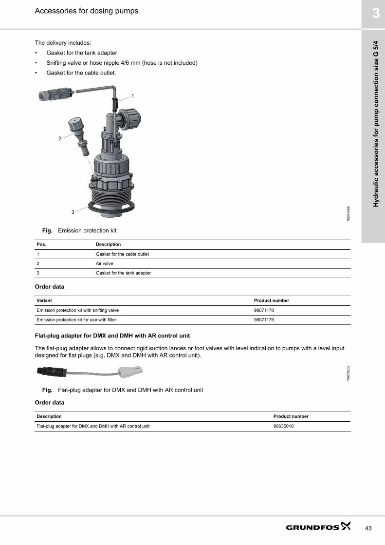
The delivery includes:
• Gasket for the tank adapter
• Snifting valve or hose nipple 4/6 mm (hose is not included)
• Gasket for the cable outlet.
1
2
3
TM06
9068
Fig. Emission protection kit
Pos. Description
1 Gasket for the cable outlet
2 Air valve
3 Gasket for the tank adapter
Order data
Variant Product number
Emission protection kit with snifting valve 98071178
Emission protection kit for use with filter 98071179
Flat-plug adapter for DMX and DMH with AR control unit
The flat-plug adapter allows to connect rigid suction lances or foot valves with level indication to pumps with a level inputdesigned for flat plugs (e.g. DMX and DMH with AR control unit).
TM07
0206
Fig. Flat-plug adapter for DMX and DMH with AR control unit
Order data
Description Product number
Flat-plug adapter for DMX and DMH with AR control unit 96635010
Accessories for dosing pumps 3
43
Hyd
raul
ic a
cces
sorie
s fo
r pum
p co
nnec
tion
size
G 5
/4

Injection unitsStandard injection unitsInjection units connect the dosing line with the process line. They ensure a minimum counterpressure and avoid backflowof the dosing medium.
TM06
8428
Fig. Standard injection unit
Injection units with ball valveInjection units with ball valve are used for applications where the injection point must be closable. The ball valve is placedbetween the injection pipe and the spring-loaded non-return valve.
• The dosing line can be completely disconnected from the process.
• The non-return valve can be disassembled and cleaned without stopping the process and emptying the process line.
TM06
8429
Fig. Injection unit with ball valve
Order data for injection units for pump connection size G 5/4
Injection units for medium-sized dosing pumps with G 5/4 connections ensure a minimum counterpressure of 0.7 bar.The delivery includes:
• Injection pipe
• immersion depth: 120 mm
• PP, PVC and PVDF versions can be shortened
• Spring-loaded non-return valve with alloy C-4 spring
• Hose and pipe connection set (PVC, PP, PVDF):
• for hoses with internal diameter 19 or 20 mm
• for pipes with external diameter 25 mm
• Pipe connection set (Stainless steel): threaded, Rp 3/4, internal thread
Dimensions of standard injection units
L1L2
A
TM06
9844
A L1 [mm] L2 [mm]
G 1 173 120
Accessories for dosing pumps3
44
Hydraulic accessories for pum
p connection size G 5/4
Order data of standard injection unitsMax. flow rate: 460 l/hThe flow rate values apply to liquids with a viscosity similar to water.
Max. pressure [bar] Material Product number
Body Gasket Ball
10 PVC FKM Ceramic 99168657
EPDM Ceramic 99168658
PTFE Ceramic 99169217
PP FKM Ceramic 99169220
EPDM Ceramic 99169223
PVDF FKM Ceramic 99169227
EPDM Ceramic 99169228
PTFE Ceramic 99169229
16 Stainless steel PTFE Stainless steel 99169230
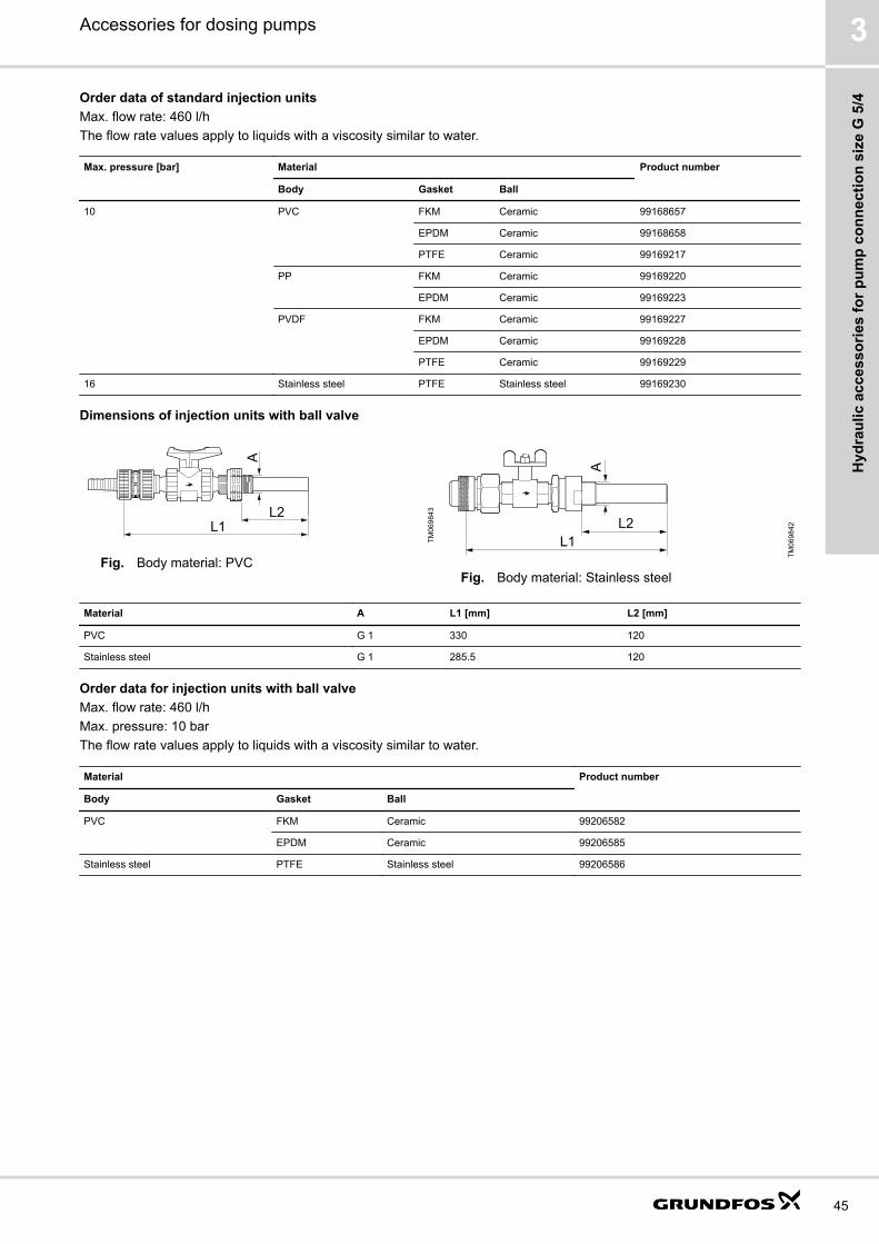
Dimensions of injection units with ball valve
L1L2
A
TM06
9843
Fig. Body material: PVCL1
L2
A
TM06
9842
Fig. Body material: Stainless steel
Material A L1 [mm] L2 [mm]
PVC G 1 330 120
Stainless steel G 1 285.5 120
Order data for injection units with ball valveMax. flow rate: 460 l/hMax. pressure: 10 barThe flow rate values apply to liquids with a viscosity similar to water.
Material Product number
Body Gasket Ball
PVC FKM Ceramic 99206582
EPDM Ceramic 99206585
Stainless steel PTFE Stainless steel 99206586
Accessories for dosing pumps 3
45
Hyd
raul
ic a
cces
sorie
s fo
r pum
p co
nnec
tion
size
G 5
/4

Pressure relief valves and pressure loading valves
Pressure relief valves PRV
Pressure relief valves PRV protect the pump and the outlet-side installations against excessive pressure. All pressuriseddosing installations should include a pressure relief valve.
TM06
8421
Fig. Pressure relief valve PRV, G 5/4
Order data for pressure relief valves PRV for pump connection size G 5/4
Pressure relief valves PRV for medium-sized dosing pumps with G 5/4 connections are installed in the outlet line near thepump using the 2 in-line connections. The side connection leads the relief liquid back into the tank.
• Relief pressure:
• factory-set to 10 bar approximately
• adjustable from 3 to 10 bar
• Max. operating pressure: 10 bar
• Max. flow rate: 460 l/h
• The flow rate values apply to liquids with a viscosity similar to water.
• Hose and pipe connection set (PVC, PP, PVDF):
• for hoses with internal diameter 19 or 20 mm
• for pipes with external diameter 25 mm
• Pipe connection set (Stainless steel): threaded, Rp 3/4, internal thread
Dimensions of PP, PVC, PVDF pressure relief valves
G
E
AB
C
I
HD
ØF
TM06
8077
A [mm] B [mm] C [mm] D [mm] E [mm] ⌀F [mm] G H [mm] I [mm]
168 30 92 6.5 150 85 G 5/4 40 75
Accessories for dosing pumps3
46
Hydraulic accessories for pum
p connection size G 5/4

Dimensions of stainless-steel pressure relief valves
AB
G
CØF
DK
G
J
TM06
8247
A [mm] B [mm] C [mm] D ⌀F [mm] G J [mm] K [mm]
167 30 63 M 6 89 Rp 3/4 10 17.5
Order data for pressure relief valves
Material Product number
Body Gaskets
PVC FKM / EPDM 99131032
PTFE 99141139
PP FKM / EPDM 99141197
PVDF FKM / EPDM 99141212
PTFE 99141224
Stainless steel - 99141228
Pressure loading valves PLV
Pressure loading valves PLV maintain a constant counterpressure for the dosing pump. They are used in the followingapplications:
• Too low counterpressure or no counterpressure at all
• Fluctuating system pressure with outlet-side pulsation damper
• To prevent syphoning, when the inlet pressure is higher than the counterpressurePressure loading valves are installed in the outlet line.Pressure loading valves should not be used as shut-off valves.
TM06
8422
Fig. Pressure loading valve PLV, G 5/4
Accessories for dosing pumps 3
47
Hyd
raul
ic a
cces
sorie
s fo
r pum
p co
nnec
tion
size
G 5
/4
Order data for pressure loading valves PLV for pump connection size G 5/4
• Loading pressure:
• factory-set to 3 bar approximately
• adjustable from 3 to 10 bar
• Max. operating pressure: 10 bar
• Max. flow rate: 460 l/h
• The flow rate values apply to liquids with a viscosity similar to water.
• Hose and pipe connection set (PVC, PP, PVDF):
• for hoses with internal diameter 19 or 20 mm
• for pipes with external diameter 25 mm
• Pipe connection set (Stainless steel): threaded, Rp 3/4, internal thread
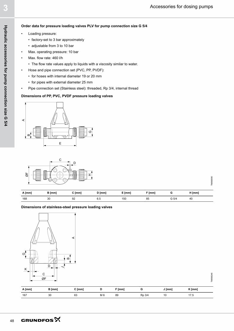
Dimensions of PP, PVC, PVDF pressure loading valves
E
B
A
G
C
H
D
ØF
TM06
8090
A [mm] B [mm] C [mm] D [mm] E [mm] F [mm] G H [mm]
168 30 92 6.5 150 85 G 5/4 40
Dimensions of stainless-steel pressure loading valves
AB
G
CØF
DK
J
TM06
8246
A [mm] B [mm] C [mm] D F [mm] G J [mm] K [mm]
167 30 63 M 6 89 Rp 3/4 10 17.5
Accessories for dosing pumps3
48
Hydraulic accessories for pum
p connection size G 5/4

Order data
Material Product number
Body Gaskets
PVC FKM / EPDM 99132186
PTFE 99140593
PP FKM / EPDM 99140610
PVDF FKM / EPDM 99140646
PTFE 99140651
Stainless steel - 99135772
Pressure valves PV
Pressure valves PV provide a constant counterpressure of 3 bar.They are particularly required for SMART Digital XL DDA-FCM pumps at very small flow rates.Pressure valves are installed either directly on the pump outlet valve, or on the pressure relief valve.
Order data for pressure valves PV for pump connection size G 5/4
• Loading pressure: 3 bar, not adjustable
• Max. operating pressure: 10 bar
• Max. flow rate: 200 l/h
• The flow rate values apply to liquids with a viscosity similar to water.
• Spring material: Alloy C-4
• No connections included
Dimensions
B
A
TM06
8404
Fig. Pressure valve PV
A [mm] B
94 G 5/4
Order data
Material Product number
Body Ball Gasket
PVC Ceramic EPDM 99229021
FKM 99229033
PVDF Ceramic EPDM 99229018
FKM 99229020
Stainless steel Stainless steel PTFE 99229034
Accessories for dosing pumps 3
49
Hyd
raul
ic a
cces
sorie
s fo
r pum
p co
nnec
tion
size
G 5
/4
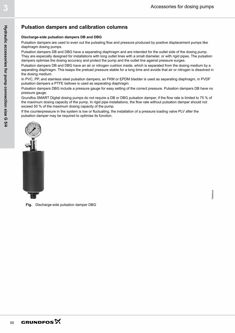
Pulsation dampers and calibration columns
Discharge-side pulsation dampers DB and DBGPulsation dampers are used to even out the pulsating flow and pressure produced by positive displacement pumps likediaphragm dosing pumps.Pulsation dampers DB and DBG have a separating diaphragm and are intended for the outlet side of the dosing pump.They are especially designed for installations with long outlet lines with a small diameter, or with rigid pipes. The pulsationdampers optimise the dosing accuracy and protect the pump and the outlet line against pressure surges.Pulsation dampers DB and DBG have an air or nitrogen cushion inside, which is separated from the dosing medium by aseparating diaphragm. This keeps the preload pressure stable for a long time and avoids that air or nitrogen is dissolved inthe dosing medium.In PVC, PP, and stainless steel pulsation dampers, an FKM or EPDM bladder is used as separating diaphragm, in PVDFpulsation dampers a PTFE bellows is used as separating diaphragm.Pulsation dampers DBG include a pressure gauge for easy setting of the correct pressure. Pulsation dampers DB have nopressure gauge.Grundfos SMART Digital dosing pumps do not require a DB or DBG pulsation damper, if the flow rate is limited to 75 % ofthe maximum dosing capacity of the pump. In rigid pipe installations, the flow rate without pulsation damper should notexceed 50 % of the maximum dosing capacity of the pump.If the counterpressure in the system is low or fluctuating, the installation of a pressure loading valve PLV after thepulsation damper may be required to optimise its function.
TM06
8424
Fig. Discharge-side pulsation damper DBG
Accessories for dosing pumps3
50
Hydraulic accessories for pum
p connection size G 5/4

Suction-side pulsation dampers CSD with calibration scale
Pulsation dampers are used to even out the pulsating flow and pressure produced by positive displacement pumps likediaphragm dosing pumps.Pulsation dampers CSD are installed on the inlet side of the dosing pump. They can be used for multiple pumps that aresupplied by the same inlet line.Pulsation dampers CSD help to ensure the accuracy of dosing pumps, which is highly dependent on proper suctionconditions. In installations with long inlet lines or inlet lines with a small diameter, the use of a CSD pulsation damper isrecommended.Pulsation dampers CSD have a transparent PVC cylinder with a fine volume scale. When combined with a shut-off valvein the inlet line, they can also be used for calibration or flow measurement. In installations without flooded suction, theoptional manual vacuum pump kit simplifies startup of the dosing pump.
TM06
8450
Fig. Suction-side pulsation dampers CSD with calibration scale
Calibration columns
Calibration columns have a graduated glass cylinder with a fine scale. A shut-off valve on the lower end can disconnectthem from the inlet-side installation during normal operation.One calibration column can be used for multiple pumps that are supplied by the same inlet line.Calibration columns must not be used as pulsation dampers.
Sizing guide for pulsation dampers and calibration columns, pump connection size G 5/4
Look up your pump type in the table. Find the required pulsation damper or calibration column volume in the respectivetable column.
Pump type Pump stroke volume [ml] Required volume [l]
DB / DBG CSD Calibration column
DDA / DDE 60-10 5.56 0.3 - 0.36 1.5 2.0
DDA / DDE 120-7 11.58
DDA / DDE 200-4 19.3
DME 60-10* 6.25 0.3 - 0.36 1.5 2.0
DME 150-4 15.6
DDI 150-4 13.9 0.3 - 0.36 1.5 2.0
DMX 17-4 10.4 0.3 - 0.36 1.5 2.0
DMX 39-4
DMX 75-4
DMX 25-3 16
DMX 60-3
Accessories for dosing pumps 3
51
Hyd
raul
ic a
cces
sorie
s fo
r pum
p co
nnec
tion
size
G 5
/4

Pump type Pump stroke volume [ml] Required volume [l]
DB / DBG CSD Calibration column
DMX 115-3 16 0.3 - 0.36 1.5 2.0
DMX 24-8 13.8 0.3 - 0.36 1.5 2.0
DMX 52-8
DMX 100-8
DMX 142-8
DMX 67-10 18.5
DMX 132-10 18.5 0.3 - 0.36 1.5 2.0
DMX 190-10 18.5 0.3 - 0.36 1.5 2.0
DMH 21-10 11.3 0.3 - 0.36 1.5 2.0
DMH 43-10
DMH 67-10
DMH 83-10
DMH 100-10
DMX 37-5 22 0.65 - 0.7 3.0 4.0
DMX 82-5
DMX 160-5
DMX 230-5
DMX 95-8 27.8
DMX 199-8 27.8 0.65 - 0.7 3.0 4.0
DMX 280-8
DMX 60-3 36 0.65 - 0.7 3.0 4.0
DMX 130-3
DMX 255-3
DMX 380-3
DMX 152-6 44.6
DMX 321-6 44.6 0.65 - 0.7 3.0 4.0
DMX 460-6
DMH 50-10 31.6 0.65 - 0.7 3.0 4.0
DMH 102-10
DMH 143-10
DMH 175-10
DMH 213-10
DMH 291-10
* A smaller damper is sufficient, if a high residual pulsation is acceptable.
Order data for pulsation dampers CSD, pump connection size G 5/4
Features• Prepared for pipe gluing connection with spigot (D) or socket (d).
• Calibration is possible by installing a T-piece and a shut-off valve.
• In installations without flooded suction, the optional manual vacuum pump kit simplifies the startup of the dosingpump.
The delivery includes:
• Sight glass with calibration scale
• Aeration valve
• Material for wall mounting
Accessories for dosing pumps3
52
Hydraulic accessories for pum
p connection size G 5/4

Dimensions
IØDØdG
HAB C
E
M
ØL
O
TM06
8373
Fig. Suction-side pulsation dampers CSD with calibration scale
Damper volume [l] A [mm] B [mm] C [mm] ⌀D / ⌀d [mm] E [mm] G [mm] H [mm] I [mm] ⌀L [mm] M [mm] O [mm]
1.5 75 343 465 25 / 20 92 19 16 70 6.5 40 8-13
3.0 79 435 568 25 / 20 92 19 16 78 60
Order dataMax. operating pressure: 2 bar
Damper volume [l] Max. pump strokevolume [ml]
Max. number of pumpswith max. stroke volume
Scale division [ml] Material Product number
Body Sight glass Gasket
1.5 19 3 20 PVC PVC FKM / EPDM 99188854
PTFE 99217403
3.0 45 2 25 PVC PVC FKM / EPDM 99190807
PTFE 99217406
Related informationManual vacuum pump kit for pulsation damper CSD. See page 101.
Order data for calibration columns, pump connection size G 5/4
Calibration columns are intended for flow measurement or calibration of dosing pumps. They must be isolated from thepipework during normal operation.The volume in the calibration column can supply the largest suitable pump for approximately 30 seconds.The delivery includes:
• Glass cylinder with acrylic outer shield
• Aeration valve on top
• Shut-off valve on the bottomIn installations without flooded suction, the optional manual vacuum pump kit simplifies the startup of the dosing pump.Calibration columns must not be used as pulsation dampers.
Accessories for dosing pumps 3
53
Hyd
raul
ic a
cces
sorie
s fo
r pum
p co
nnec
tion
size
G 5
/4

Dimensions
Ød
AB
ØD
ØCHH
EØF
TM06
8405
Fig. Calibration column
Volume [l] Body A [mm] B [mm] ⌀C [mm] ⌀D [mm] E ⌀F [mm] H [mm]
2.0 PVDF 675 188 12 101.6 M 10 12 78-182
SS 657 148
4.0 PVDF 795 188 12 132 M 10 12 92-196
SS 777 148
Order data
Volume [l] Max. pump stroke volume [ml] Scale division [ml] Connection ⌀d Material Product number
[mm] Body Gasket
2.0 19 20 25 - PVDF FKM 99224309
- G 1 SS FKM 99224310
SS EPDM 99224311
4.0 45 25 25 - PVDF FKM 99224312
- G 1 SS FKM 99224313
SS EPDM 99224314
Related informationManual vacuum pump kit for calibration columns. See page 102.
Order data for pulsation dampers DB and DBG, pump connection size G 5/4
We recommend using one pulsation damper per dosing pump.Preload pressure: 2.7 bar.The delivery includes:
• Material for wall mounting
• PVC versions are prepared for pipe gluing connection with spigot (D) or socket (d).
• PVDF and PP versions are prepared for pipe welding connection with spigot (D) or socket (d).
• Pulsation dampers DBG include a pressure gauge.
Accessories for dosing pumps3
54
Hydraulic accessories for pum
p connection size G 5/4

Dimensions
A2
A3
A1
B
H
H
EØF
ØD1ØD
G
ØdTM
0682
84
Fig. Pulsation damper DBG, PVC version
ØD2
G
A2
A1
ØD1
HH
EØF
B
TM06
8452
Fig. Pulsation damper DBG, stainless steel version
B [mm] ⌀F [mm] E
129 12 M 10
Damper volume [l] Body material Connections A1 [mm] A2 [mm] A3 [mm] ⌀D1 [mm] ⌀D2 [mm] H [mm]
⌀D/⌀d [mm] G Internal thread
0.3 PVDF 25/20 G 3/4 267 20 25 84 63 58-175
0.36 PVC, PP 25/20 G 3/4 203 20 25 90 - 71-175
SS* - G 1/2 161 16 - 85 - 67-171
0.65 PVC, PP 25/20 G 3/4 263 20 25 100 - 78-152
SS* - G 3/4 205 20 - 90 84 67-171
0.7 PVDF 25/20 G 3/4 138 20 25 98 84 67-171
* Stainless steel 1.4404
Order data
Dampervolume [l]
Max. pumpstroke volume[ml]
Connections Material Type DB Type DBG
⌀D/⌀d[mm]
G Internalthread
Body Gasket Max. operatingpressure [bar]
Productnumber
Max. operatingpressure [bar]
Productnumber
0.36 19 25/20 G 3/4 PVC FKM 10 99202662 10 99202687
EPDM 10 99202663 10 99202688
PP FKM 10 99202664 10 99202689
EPDM 10 99202665 10 99202690
- G 1/2 SS FKM 180 99202667 25 99202692
EPDM 180 99202669 25 99202693
0.3 19 25/20 G 3/4 PVDF PTFE 20 99202666 20 99202691
Accessories for dosing pumps 3
55
Hyd
raul
ic a
cces
sorie
s fo
r pum
p co
nnec
tion
size
G 5
/4
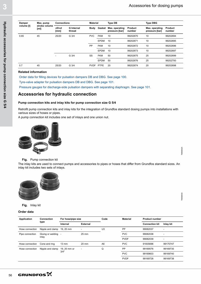
Dampervolume [l]
Max. pumpstroke volume[ml]
Connections Material Type DB Type DBG
⌀D/⌀d[mm]
G Internalthread
Body Gasket Max. operatingpressure [bar]
Productnumber
Max. operatingpressure [bar]
Productnumber
0.65 45 25/20 G 3/4 PVC FKM 10 99202670 10 99202694
EPDM 10 99202671 10 99202695
PP FKM 10 99202672 10 99202696
EPDM 10 99202673 10 99202697
- G 3/4 SS FKM 50 99202675 25 99202699
EPDM 50 99202676 25 99202700
0.7 45 25/20 G 3/4 PVDF PTFE 20 99202674 20 99202698
Related informationOrder data for filling devices for pulsation dampers DB and DBG. See page 100.
Tyre-valve adapter for pulsation dampers DB and DBG. See page 101.
Pressure gauges for discharge-side pulsation dampers with separating diaphragm. See page 101.
Accessories for hydraulic connection
Pump connection kits and inlay kits for pump connection size G 5/4
Retrofit pump connection kits and inlay kits for the integration of Grundfos standard dosing pumps into installations withvarious sizes of hoses or pipes.A pump connection kit includes one set of inlays and one union nut.
TM06
8425
Fig. Pump connection kitThe inlay kits are used to connect pumps and accessories to pipes or hoses that differ from Grundfos standard sizes. Aninlay kit includes two sets of inlays.
TM06
8430
Fig. Inlay kit
Order data
Application Connectiontype
For hose/pipe size Code Material Product number
Internal External Connection kit Inlay kit
Hose connection Nipple and clamp 19, 20 mm - U3 PP 99082037 -
Pipe connection Gluing or weldinginlay
- 25 mm PVC 99082038 -
PVDF 99082039 -
Hose connection Cone and ring 13 mm 20 mm A6 PVC 91835696 99170747
Hose connection Nipple and clamp 19, 20 mm or3/4"
- Q PP 99169576 99169735
PVC 99169603 99169740
PVDF 99169728 99169738
Accessories for dosing pumps3
56
Hydraulic accessories for pum
p connection size G 5/4

Application Connectiontype
For hose/pipe size Code Material Product number
Internal External Connection kit Inlay kit
Pipe connection Welding inlay - 25 mm B4 PP 91835697 99171119
PVDF 91835698 99171146
DN 20, 3/4" C0 SS 99369686 -
Pipe connection Gluing inlay - 25 mm B0 PVC 96701989 99171177
3/4" pipe (US) or26.6 mm (BS)
C7 PVC 99170858 99171222
Pipe connection External thread 3/4 NPT A7 PVC 99082040 99171707
PP 99082041 99171776
PVDF 99082042 99171793
Pipe connection Internal thread Rp 3/4 A1 PP 99082043 99182104
PVDF 99082044 99182109
SS* 99082045 99182114
Alloy C-4 ** 99082046 99182136
3/4 NPT A3 PP 99082047 99174974
PVDF 99082048 99175004
SS* 99082049 99175015
Alloy C-4 ** 99082050 99175031
Pipe connection Cutting-ring type 19 mm 22 mm C3 SS* 96727555 -
* Union nut: Stainless steel 1.4401, inlay: Stainless steel 1.4571** 2.4610 (Alloy C-4)
Threaded adapters G 5/4
With threaded adapters, different sizes of threaded connections can be connected. A threaded adapter includes a gasket.
Technical dataType Threaded connection size Material Product number
Internal thread External thread Body Gaskets
TM04
8301
G 5/4 G 5/8 PP FKM / EPDM 95730432
PVC FKM / EPDM 95730433
PTFE 95730434
PVDF FKM / EPDM 95730435
PTFE 95730436
TM06
8416
G 5/4 G 3/4 PP FKM / EPDM 99227512
PVC FKM / EPDM 99227511
PTFE 99228197
PVDF FKM / EPDM 99227829
PTFE 99227533
Accessories for dosing pumps 3
57
Hyd
raul
ic a
cces
sorie
s fo
r pum
p co
nnec
tion
size
G 5
/4

Adapters G 5/4
Union nut adaptersWith a union nut adapter, a pressure loading valve PLV or a pressure relief valve PRV can be mounted directly on thepump outlet valve.Union nut adapters consist of a rigid pipe with union nuts on both ends.
Technical dataType Threaded connection size Body material Product number
Internal thread Internal thread
TM06
8418
G 5/4 G 5/4 PP 99228667
PVC 99228665
PVDF 99228669
Elbow adapterAn elbow adapter can be installed, if the space on the inlet side of the pump is confined.
Technical dataType Threaded connection size Body material Product number
Internal thread External thread
TM06
8129
G 5/4 G 5/4 PVC 99168768
Preassembled accessories set for SMART Digital XLThe preassembled accessories set includes a pressure loading valve, a pressure relief valve and a pulsation damper aswell as mounting material for a SMART Digital XL DDA or DDE pump.The mounting material includes a bracket with screws and washers. The bracket can be mounted to a wall or directly on aGrundfos dosing tank. Suitable tank sizes are 200 l, 300 l, 500 l and 1000 l.Main components of the outlet-side assembly:
• Pressure loading valve PLV, preset to approx. 3 bar loading pressure (adjustable to up to 10 bar)
• Pressure relief valve PRV, preset to approx. 6 bar relief pressure (adjustable to up to 10 bar)
• Pulsation damper DBG with a volume of 0.36 l, with pressure gauge, preloaded to 2.7 bar (preloadable to up to 8 bar)
• Optionally without pulsation damper. For installation without pulsation damper observe the following:
• For installation with rigid pipes, the pump must be limited to 50 % of its maximum dosing capacity.
• For installation with hoses, the pump must be limited to 75 % of its maximum dosing capacity.
Order dataVariant Material Product number
Body Gaskets
With pulsation damper PVC FKM 99211372
EPDM 99211483
Without pulsation damper PVC FKM 99211484
EPDM 99211485
Accessories for dosing pumps3
58
Hydraulic accessories for pum
p connection size G 5/4

Dimensions
M L
KJ
IH N
TM06
8419
Fig. Preassembled accessories set in side view
D
FC
E
AG
B
TM06
8420
Fig. Preassembled accessories set in back view
A[mm]
B[mm]
C [mm] D[mm]
E[mm]DDA / DDE 60-10 DDA / DDE 120-7 DDA / DDE 200-4
117 203 332.5 348 358 410 435
F [mm] G [mm] H [mm] I [mm] J [mm] K [mm] L [mm] M [mm] N [mm]
346.5 218 20 385 112 298 51 234 280
Accessories for dosing pumps 3
59
Hyd
raul
ic a
cces
sorie
s fo
r pum
p co
nnec
tion
size
G 5
/4

4. Hydraulic accessories for pump connection size G 2
Overview of accessories for pump connection size G 2Grundfos offer a comprehensive range of accessories covering every need when dosing with Grundfos pumps.
1
2
3
4
5
6
8
7
9
10
11
TM07
0519
Pos. Description See section
1 Injection units Injection units for pump connection size G 2 on page 63
2 Pulsation dampers DBG Order data for pulsation dampers DB and DBG, pump connection size G 2 on page 68
3 Pressure loading valves PLV Order data for pressure loading valves PLV for pump connection size G 2 on page 64
4 Pressure relief assembly Relief assembly for pressure loading valves PLV with G 2 connection on page 65
5 Cables and plugs Cables and plugs for DME pumps on page 106
6 Manual vacuum pump kits Order data for pulsation dampers CSD, pump connection size G 2 on page 67
7 Pulsation dampers CSD
8 Hoses Hoses for dosing pump connection size G 2 on page 61
9 Adapter for rigid suction lances RSL Rigid suction lances RSL with connection size G 2 on page 62
10 Rigid suction lances RSL
11 Foot valves FV Foot valves FV with connection size G 2 on page 61
- Pump connection inlay kits and union nut kits Pump connection inlay kits and union nut kits for pump connection size G 2 on page 70
Accessories for dosing pumps4
60
Hydraulic accessories for pum
p connection size G 2

Hoses for dosing pump connection size G 2Hoses in various materials, sizes and lengths for dosing pumps.Pump connection size: G 2
TM01
8958
Fig. Hoses
Order dataThe flow rate values apply to liquids with a viscosity similar to water.
Max. flow rate [l/h] Size (internal/externaldiameter) [mm]
Material Max. pressure [bar] Length [m] Product number
200* 15/20 PVC 0.5 2 96535081
940 32/41 PVC, textile-reinforced 9 5 96535077
10 96535079
* Relief line for DME dosing head with included dearation/pressure relief valve
Foot valves FV with connection size G 2Foot vales G 2 have no level indication.The delivery includes:
• Strainer (mesh size approx. 1 mm)
• Non-return valve
• Pipe connection set (PVC, PP, PVDF): for pipes with external diameter 40 mm
• Pipe connection set (stainless steel): threaded, Rp 1 1/4, internal threadLevel switches are available as accessories for foot valves. A level switch can be retrofitted, if the foot valve is installedwith a pipe with 40 mm external diameter.
Dimensions
L
d
TM06
9925
Fig. Foot valve FV
Material d [mm] L [mm]
PVC, PP, PVDF 71.5 75
Stainless steel (SS) 70 75
Accessories for dosing pumps 4
61
Hyd
raul
ic a
cces
sorie
s fo
r pum
p co
nnec
tion
size
G 2

Order dataThe flow rate values apply to liquids with a viscosity similar to water.
Max. flow rate [l/h] Material Product number
Body Gasket Ball
1150 PVC FKM Glass 99352896
EPDM PTFE 99352897
PTFE PTFE 99352898
PP FKM Glass 99352899
EPDM PTFE 99352900
PVDF FKM PTFE 99352902
PTFE PTFE 99352903
SS PTFE SS 99352904
Rigid suction lances RSL with connection size G 2These rigid suction lances are designed for the use with stationary tanks (e.g. Grundfos tanks). Rigid suction lances forstationary tanks have a foot valve with strainer. Level switches are available as accessories and can be retrofitted. Thelength of the rigid pipe can be adapted to the customer's requirements. The pipe can be cut and assembled without gluing.The delivery includes:
• Strainer (mesh size approx. 0.8 mm)
• Non-return valve
• Pipe connection set (PVC): for pipes with external diameter 40 mm
• Adjustable tank connection
Dimensions
ØB
A
C
D
G
F
ØE
TM06
9952
Fig. Rigid suction lance RSL
A [mm] ⌀B [mm] C [mm] D [mm] ⌀E [mm] F G [mm]
87 40 1342 1200 66 G 2 40
Order dataThe flow rate values apply to liquids with a viscosity similar to water.
Max. flow rate [l/h] Max. immersion depth[mm]
Material Product number
Body Gasket Ball
1150 1200 PVC / PVDF FKM Glass 99328221
EPDM Glass 99328227
Accessories for dosing pumps4
62
Hydraulic accessories for pum
p connection size G 2

Accessories for rigid suction lances RSL
Adapters for container connection
These adapters allow the installation of standard rigid suction lances (G 2 thread) on different types of containers.
Order dataType For container type Material Product number
TM04
8470 Counter nut for tanks without threaded opening, e.g. 100-litre
square tank or 1000-litre cylindrical tankPVC, grey 98071170
TM04
8472 IBC (Intermediate Bulk Container) with opening of ⌀150 mm, S
160 x 7PE, black 98071177
Injection units for pump connection size G 2Injection units connect the dosing line with the process line. Injection units for large dosing pumps with G 2 connectionsensure a minimum counterpressure of 0.6 bar.The delivery includes:
• Injection pipe
• immersion depth: 120 mm
• PP, PVC and PVDF versions can be shortened
• Spring-loaded non-return valve with alloy C-4 spring
• Pipe connection set (PVC, PP, PVDF): for pipes with external diameter 40 mm
• Pipe connection set (Stainless steel): threaded, Rp 1 1/4, internal thread
Dimensions
B C
A
TM06
9992
Fig. Injection unit
A B [mm] C [mm]
G 2 78 120
Order data• Max. flow rate: 1500 l/h
• The flow rate values apply to liquids with a viscosity similar to water.
Max. pressure [bar] Material Product number
Body Gasket Ball
10 PVC FKM Glass 99332974
EPDM PTFE 99333838
PTFE PTFE 99333839
PP FKM Glass 99333903
EPDM PTFE 99333904
PVDF FKM PTFE 99333905
EPDM PTFE 99333907
PTFE PTFE 99333909
Stainless steel PTFE Stainless steel 99333910
Accessories for dosing pumps 4
63
Hyd
raul
ic a
cces
sorie
s fo
r pum
p co
nnec
tion
size
G 2

Pressure loading valves PLVPressure loading valves PLV maintain a constant counterpressure for the dosing pump. They are used in the followingapplications:
• Too low counterpressure or no counterpressure at all
• Fluctuating system pressure with outlet-side pulsation damper
• To prevent syphoning, when the inlet pressure is higher than the counterpressurePressure loading valves are installed in the outlet line.Pressure loading valves should not be used as shut-off valves.
TM07
0220
Fig. Pressure loading valve PLV, G 2
Order data for pressure loading valves PLV for pump connection size G 2
• Loading pressure: adjustable from 0.5 to 10 bar
• Max. operating pressure: 10 bar
• Max. flow rate: 1500 l/h
• The flow rate values apply to liquids with a viscosity similar to water.
• Pipe connection set (PVC, PP, PVDF): for pipes with external diameter 40 mm
• Pipe connection set (Stainless steel): threaded, Rp 1 1/4, internal thread
Dimensions
E
A
B
G
C
J
D
ØF
TM07
0289
Fig. Body material: PVC, PP, PVDF
AB
ØF
E
G
C
D
J
TM07
0296
Fig. Body material: Stainless steel
Body material A [mm] B [mm] C [mm] D E [mm] ⌀F [mm] G J [mm]
PVC, PP 276 57 65 M 8 205 148 G 2 20.4
PVDF 318 56 65 M 8 200 147
Stainless steel 245 24.5 65 M 8 102 148 Rp 1 1/4 20.5
Accessories for dosing pumps4
64
Hydraulic accessories for pum
p connection size G 2

Order data
Material Product number
Body Gaskets
PVC FKM / EPDM 99367198
PTFE 99367199
PP FKM / EPDM 99367200
PVDF FKM / EPDM 99367201
PTFE 99367203
Stainless steel - 99367204
Relief assembly for pressure loading valves PLV with G 2 connection
Pressure relief valves protect the pump and the outlet-side installations against excessive pressure. All pressurised dosinginstallations should include a pressure relief valve.Pressure relief valves are installed in the outlet line near the pump. A pressure relief valve for a large dosing pump can becreated by combining a T-piece and a PLV to a relief assembly. The relief line is connected to the outlet of the PLV.The delivery includes:
• T-piece with union nut for connection of the PLV
• Pipe connection for pipes with external diameter of 40 mmThe pressure loading valve PLV is not included and must be ordered separately.
Dimensions
ØC
ED
AB
B
TM07
0283
Fig. Relief assembly for pressure loading valves
A [mm] B [mm] ⌀C [mm] D [mm] E [mm]
98 26 40 78 205
Order dataThe flow rate values apply to liquids with a viscosity similar to water.
Max. flow rate [l/h] Material Product number
1500 PVC 99370957
PP 99370958
PVDF 99370960
Pulsation dampers
Discharge-side pulsation dampers DB and DBGPulsation dampers are used to even out the pulsating flow and pressure produced by positive displacement pumps likediaphragm dosing pumps.Pulsation dampers DB and DBG have a separating diaphragm and are intended for the outlet side of the dosing pump.They are especially designed for installations with long outlet lines with a small diameter, or with rigid pipes. The pulsationdampers optimise the dosing accuracy and protect the pump and the outlet line against pressure surges.Pulsation dampers DB and DBG have an air or nitrogen cushion inside, which is separated from the dosing medium by aseparating diaphragm. This keeps the preload pressure stable for a long time and avoids that air or nitrogen is dissolved inthe dosing medium.
Accessories for dosing pumps 4
65
Hyd
raul
ic a
cces
sorie
s fo
r pum
p co
nnec
tion
size
G 2

In PVC, PP, and stainless steel pulsation dampers, an FKM or EPDM bladder is used as separating diaphragm, in PVDFpulsation dampers a PTFE bellows is used as separating diaphragm.Pulsation dampers DBG include a pressure gauge for easy setting of the correct pressure. Pulsation dampers DB have nopressure gauge.If the counterpressure in the system is low or fluctuating, the installation of a pressure loading valve PLV after thepulsation damper may be required to optimise its function.
TM06
8424
Fig. Discharge-side pulsation damper DBG
Suction-side pulsation dampers CSD with calibration scale
Pulsation dampers are used to even out the pulsating flow and pressure produced by positive displacement pumps likediaphragm dosing pumps.Pulsation dampers CSD are installed on the inlet side of the dosing pump. They can be used for multiple pumps that aresupplied by the same inlet line.Pulsation dampers CSD help to ensure the accuracy of dosing pumps, which is highly dependent on proper suctionconditions. In installations with long inlet lines or inlet lines with a small diameter, the use of a CSD pulsation damper isrecommended.Pulsation dampers CSD have a transparent PVC cylinder with a fine volume scale. When combined with a shut-off valvein the inlet line, they can also be used for calibration or flow measurement. In installations without flooded suction, theoptional manual vacuum pump kit simplifies startup of the dosing pump.
TM06
8450
Fig. Suction-side pulsation dampers CSD with calibration scale
Accessories for dosing pumps4
66
Hydraulic accessories for pum
p connection size G 2
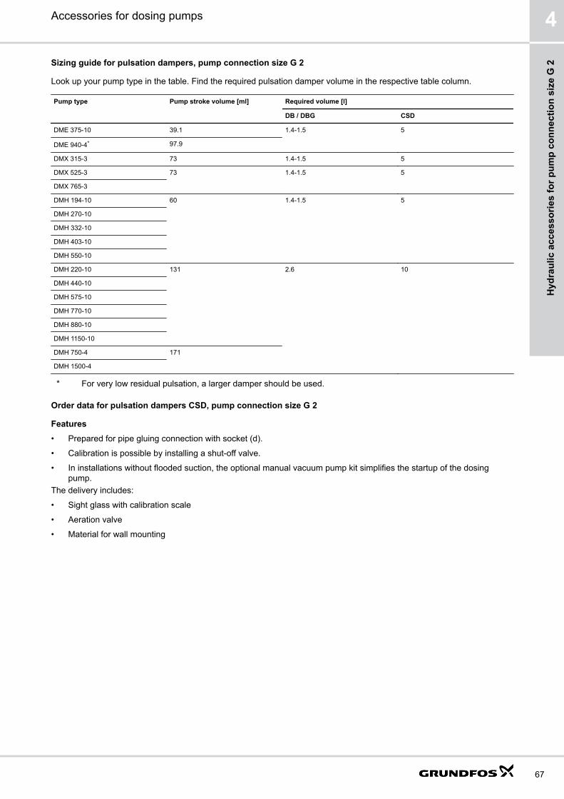
Sizing guide for pulsation dampers, pump connection size G 2
Look up your pump type in the table. Find the required pulsation damper volume in the respective table column.
Pump type Pump stroke volume [ml] Required volume [l]
DB / DBG CSD
DME 375-10 39.1 1.4-1.5 5
DME 940-4* 97.9
DMX 315-3 73 1.4-1.5 5
DMX 525-3 73 1.4-1.5 5
DMX 765-3
DMH 194-10 60 1.4-1.5 5
DMH 270-10
DMH 332-10
DMH 403-10
DMH 550-10
DMH 220-10 131 2.6 10
DMH 440-10
DMH 575-10
DMH 770-10
DMH 880-10
DMH 1150-10
DMH 750-4 171
DMH 1500-4
* For very low residual pulsation, a larger damper should be used.
Order data for pulsation dampers CSD, pump connection size G 2
Features• Prepared for pipe gluing connection with socket (d).
• Calibration is possible by installing a shut-off valve.
• In installations without flooded suction, the optional manual vacuum pump kit simplifies the startup of the dosingpump.
The delivery includes:
• Sight glass with calibration scale
• Aeration valve
• Material for wall mounting
Accessories for dosing pumps 4
67
Hyd
raul
ic a
cces
sorie
s fo
r pum
p co
nnec
tion
size
G 2

DimensionsØ
d
MH
ØD
AE
C
ØL
B
O
I
G
TM07
0034
Fig. Suction-side pulsation dampers CSD with calibration scale
Damper volume [l] A [mm] B [mm] C [mm] ⌀d [mm] ⌀D [mm] E [mm] G [mm] H [mm] I [mm] ⌀L [mm] M [mm] O [mm]
5 118.5 700 871 40 50 92 51 71.5 77.5 6.5 60 8-13
10 139.5 600 824 5040
63 92 64 111.5 95 6.5 90 8-13
Order dataMax. operating pressure: 2 bar
Damper volume [l] Max. pump stroke volume[ml]
Max. number of pumps with max.stroke volume
Scale division [ml] Material Product number
Body Sight glass
5 75 3 10 PVC PVC 99192488
10 171 3 50 PVC PVC 99194326
Related informationManual vacuum pump kit for pulsation damper CSD. See page 101.
Order data for pulsation dampers DB and DBG, pump connection size G 2
We recommend using one pulsation damper per dosing pump.Preload pressure: 2.7 bar.The delivery includes:
• Material for wall mounting
• PVC versions are prepared for pipe gluing connection with spigot (D) or socket (d).
• PVDF and PP versions are prepared for pipe welding connection with spigot (D) or socket (d).
• Pulsation dampers DBG include a pressure gauge.
Accessories for dosing pumps4
68
Hydraulic accessories for pum
p connection size G 2

Dimensions
A2
A3
A1
B
H
H
EØF
ØD1ØD
G
ØdTM
0682
84
Fig. Pulsation damper DBG, PVC version
ØD2
G
A2
A1
ØD1
HH
EØF
B
TM06
8452
Fig. Pulsation damper DBG, stainless steel version
B [mm] ⌀F [mm] E
129 12 M 10
Damper volume [l] Body material Connections A1 [mm] A2 [mm] A3 [mm] ⌀D1 [mm] ⌀D2 [mm] H [mm]
⌀D/⌀d [mm] G Internal thread
1.5 PVC, PP 40/32 G 1 335 22 28 130 - 90-190
1.4 PVDF 40/32 G 3/4 294 22 28 125 104 77-177
1.5 SS* - G 3/4 245 25 - 110 104 77-177
2.6 PVC, PP 40/32 G 1 365 22 28 160 - 105-205
PVDF 40/32 G 3/4 360 22 28 170 156 103-203
SS* - G 1 295 27 - 140 129 89.5 - 189.5
* Stainless steel 1.4404
Order data
Dampervolume [l]
Max. pumpstroke volume[ml]
Connections Material Type DB Type DBG
⌀D/⌀d[mm]
G Internalthread
Body Gasket Max. operatingpressure [bar]
Productnumber
Max. operatingpressure [bar]
Productnumber
1.5 75 40/32 G 1 PVC FKM 10 99331670 10 99332053
EPDM 10 99331671 10 99332054
PP FKM 10 99331672 10 99332055
EPDM 10 99331693 10 99332056
1.4 75 40/32 G 3/4 PVDF PTFE 20 99331694 20 99332057
1.5 75 - G 3/4 SS FKM 40 99331695 25 99332058
EPDM 40 99331696 25 99332059
Accessories for dosing pumps 4
69
Hyd
raul
ic a
cces
sorie
s fo
r pum
p co
nnec
tion
size
G 2

Dampervolume [l]
Max. pumpstroke volume[ml]
Connections Material Type DB Type DBG
⌀D/⌀d[mm]
G Internalthread
Body Gasket Max. operatingpressure [bar]
Productnumber
Max. operatingpressure [bar]
Productnumber
2.6 171 40/32 G 1 PVC FKM 10 99333783 10 99333827
EPDM 10 99333784 10 99333828
PP FKM 10 99333785 10 99333829
EPDM 10 99333786 10 99333830
G 3/4 PVDF PTFE 20 99333787 20 99333831
- G 1 SS FKM 30 99333788 25 99333832
EPDM 30 99333789 25 99333843
Related informationOrder data for filling devices for pulsation dampers DB and DBG. See page 100.
Tyre-valve adapter for pulsation dampers DB and DBG. See page 101.
Pressure gauges for discharge-side pulsation dampers with separating diaphragm. See page 101.
Accessories for hydraulic connection
Pump connection inlay kits and union nut kits for pump connection size G 2
Retrofit pump connection kits and inlay kits for the integration of Grundfos standard pumps into installations with varioussizes of hoses or pipes.The inlay kits are used to connect pumps to pipes and hoses that differ from Grundfos standard size.
TM06
8430
Fig. Inlay kit
Order data for inlay kitsAn inlay kit includes 2 sets of inlays.
Application Connection type For hose/pipe size Connector typekey code
Material Product number
Internal External
Hose connection Nipple and clamp 32 mm, 41 mm1 1/4", 1 1/2"
- C5 PP 96535111
PVC 99338732
PVDF 96535112
Pipe connection Welding inlay - 40 mm B5 PP 99305837
PVDF 99305838
- DN 32, 1 1/4" C1 SS 99369687
Pipe connection Gluing inlay - 40 mm K PVC 99305839
- 52.5 mm, 1 1/4" C8 PVC 99338595
Pipe connection External thread - 1 1/4 NPT A8 PVC 99305732
PP 99305743
PVDF 99305745
Pipe connection Internal thread Rp 1 1/4 - A2 PP 96608418
A2 PVDF 96608419
A2 SS 96575258
1 1/4 NPT - A4 SS 96537895
Accessories for dosing pumps4
70
Hydraulic accessories for pum
p connection size G 2

Order data for union nut kitsA union nut kit includes 2 union nuts.
Application Material Product number
DMXAccessories for dosing pumps
PVC 99307539
PP 99307540
PVDF 99307541
DMXAccessories for dosing pumpsDME 375-10, DME 940-4
SS 96731914
DME 375-10, DME 940-4 PP 96731916
PVDF 96731915
Counter flange sets for DMH 255/257Suitable for DMH 257 and suction side of DMH 255. A kit includes one counter flange.
Application Connection type Pipe size external Material Product number
Pipe connection Gluing 40 mm PVC 91835728
Welding 40 mm PP 96727589
PVDF 96727588
42.4 mm, DN 32 SS 91835727
Alloy C-4 96727609
Threaded adapters G 2
With threaded adapters, different sizes of threaded connections can be connected. A threaded adapter includes a gasket.
Type Threaded connection size Material Product number
Internal thread External thread Body Gaskets
TM06
8417
G 2 G 5/4 PP FKM / EPDM 99227945
PVC FKM / EPDM 99227943
PTFE 99227960
PVDF FKM / EPDM 99227953
PTFE 99227948
Flange adapters DN 32
With flange adapters, accessories with G 2 connections can be connected to a dosing pump with DN 32 flanges. A flangeadapter includes a gasket for the threaded connection side.
Dimensions
B
A
ØCØD
TM07
0343
A [mm] B ⌀C [mm] ⌀D [mm]
68 G 2 18 100
Accessories for dosing pumps 4
71
Hyd
raul
ic a
cces
sorie
s fo
r pum
p co
nnec
tion
size
G 2

Order dataFlange Threaded connection size Material Product number
External thread Body Gaskets
DN 32 G 2 PP FKM / EPDM 99307979
PVC FKM / EPDM 99307977
PTFE 99307978
PVDF FKM / EPDM 99307980
PTFE 99307981
Accessories for dosing pumps4
72
Hydraulic accessories for pum
p connection size G 2
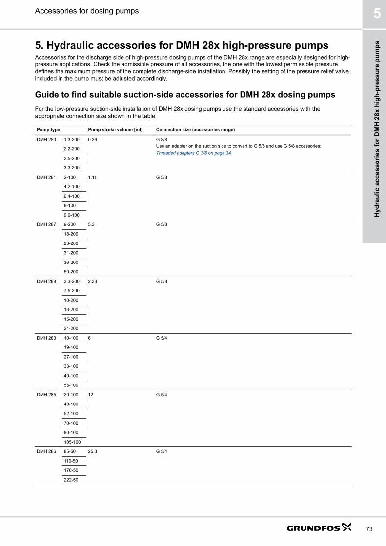
5. Hydraulic accessories for DMH 28x high-pressure pumpsAccessories for the discharge side of high-pressure dosing pumps of the DMH 28x range are especially designed for high-pressure applications. Check the admissible pressure of all accessories, the one with the lowest permissible pressuredefines the maximum pressure of the complete discharge-side installation. Possibly the setting of the pressure relief valveincluded in the pump must be adjusted accordingly.
Guide to find suitable suction-side accessories for DMH 28x dosing pumpsFor the low-pressure suction-side installation of DMH 28x dosing pumps use the standard accessories with theappropriate connection size shown in the table.
Pump type Pump stroke volume [ml] Connection size (accessories range)
DMH 280 1.3-200 0.36 G 3/8Use an adapter on the suction side to convert to G 5/8 and use G 5/8 accessories:Threaded adapters G 3/8 on page 34
2.2-200
2.5-200
3.3-200
DMH 281 2-100 1.11 G 5/8
4.2-100
6.4-100
8-100
9.6-100
DMH 287 9-200 5.3 G 5/8
18-200
23-200
31-200
36-200
50-200
DMH 288 3.3-200 2.33 G 5/8
7.5-200
10-200
13-200
15-200
21-200
DMH 283 10-100 6 G 5/4
19-100
27-100
33-100
40-100
55-100
DMH 285 20-100 12 G 5/4
40-100
52-100
70-100
80-100
105-100
DMH 286 85-50 25.3 G 5/4
110-50
170-50
222-50
Accessories for dosing pumps 5
73
Hyd
raul
ic a
cces
sorie
s fo
r DM
H 2
8x h
igh-
pres
sure
pum
ps

Injection units for DMH 28x high-pressure dosing pumpsInjection units connect the dosing line with the process line. They ensure a minimum counterpressure of 0.7 bar and avoidbackflow of the dosing liquid.
Dimensions
CB
A
TM07
0227
Fig. High-pressure injection unit, flow rate 3.3 l/h
CB
A
TM07
0259
Fig. High-pressure injection unit, flow rate 55 l/h
CB
A
TM07
0236
Fig. High-pressure injection unit, flow rate 220 l/h
Max. flow rate [l/h] A B [mm] C [mm]
3.3 G 1/2 90.0 27
55 G 1/2 77.5 27
220 G 1 75 120
Order dataThe flow rate values apply to liquids with a viscosity similar to water.
Max. flow rate [l/h] Max. operating pressure [bar] Dosing line connection size Material Product number
Body, Ball Gasket
3.3 200 4/6 mm Stainless steel PTFE 99354318
55 200 8/10 mm Stainless steel PTFE 99367393
55 200 10/12 mm Stainless steel PTFE 99354320
220 100 G 3/4 Stainless steel PTFE 99354315
Accessories for dosing pumps5
74
Hydraulic accessories for D
MH
28x high-pressure pumps

Pressure relief valves PRV for DMH 28x high-pressure dosing pumpsPressure relief valves are installed in the outlet line near the pump using the 2 in-line connections. The side connectionleads the relief liquid back into the tank.
Dimensions
AB
C
D
TM07
0299
Fig. Pressure relief valve, max. flow rate 3.3 l/h
Max. flow rate [l/h] A [mm] B [mm] C [mm] D [mm]
3.3 54 41 66 133
50 72 41 75 142
55 72 46 84 187
Order dataThe flow rate values apply to liquids with a viscosity similar to water.
Max. flow rate [l/h] Max. opening pressure range [bar] Dosing line connection size [mm] Material Product number
Body Gasket
3.3 51103206
4/6 Stainless steel FKM 99362083
50 103206
10/12 Stainless steel FKM 99362085
55 24103
10/12 Stainless steel FKM 99362086
Accessories for dosing pumps 5
75
Hyd
raul
ic a
cces
sorie
s fo
r DM
H 2
8x h
igh-
pres
sure
pum
ps

Pulsation dampers for DMH 28x high-pressure dosing pumps
Sizing guide for pulsation dampers for DMH 28x high-pressure dosing pumps
This sizing guide applies to suction-side and discharge-side pulsation dampers. Look up your pump type in the tablebelow.
Pump type Pump stroke volume [ml] Required volume [l]
DB / DBG-H CSD
DMH 280 1.3-200 0.36 0.09 0.25
2.2-200
2.5-200
3.3-200
DMH 288 3.3-200 2.33 0.09 0.5
7.5-200
10-200
13-200
15-200
21-200
DMH 287 9-200 5.3 0.09 0.5
18-200
23-200
31-200
36-200
50-200
DMH 281 2-100 1.11 0.18 0.5
4.2-100
6.4-100
8-100
9.6-100
DMH 283 10-100 6 0.36 1.5
19-100
27-100
33-100
40-100
55-100
DMH 285 20-100 12 0.36 1.5
40-100
52-100
70-100
80-100
105-100
DMH 286 85-50 25.3 0.36 3
110-50
170-50
222-50
Related informationOrder data for pulsation dampers CSD, pump connection size G 5/8. See page 28.
Order data for pulsation dampers CSD, pump connection size G 5/4. See page 52.
Order data for pulsation dampers DB and DBG-H for DMH 28x high-pressure dosing pumps. See page 77.
Accessories for dosing pumps5
76
Hydraulic accessories for D
MH
28x high-pressure pumps

Discharge-side pulsation dampers DB and DBG-HPulsation dampers are used to even out the pulsating flow and pressure produced by positive displacement pumps likediaphragm dosing pumps.Pulsation dampers DB and DBG-H are especially designed for installations with long outlet lines with a small diameter, orwith rigid pipes. The pulsation dampers optimise the dosing accuracy and protect the pump and the outlet line againstpressure surges.Pulsation dampers DB and DBG-H have a nitrogen cushion inside, which is separated from the dosing medium by aseparating diaphragm. This keeps the preload pressure stable for a long time and avoids that nitrogen is dissolved in thedosing medium. A FKM or EPDM bladder is used as separating diaphragm.Pulsation dampers DBG-H include a pressure gauge for easy setting of the correct pressure. Pulsation dampers DB haveno pressure gauge.
Order data for pulsation dampers DB and DBG-H for DMH 28x high-pressure dosing pumps
We recommend using one pulsation damper per dosing pump.Preload pressure: 2.7 bar.The pulsation dampers are filled with air in the factory. For use in high-pressure dosing systems (> 10 bar), the air must bereplaced with nitrogen.The delivery includes:
• Material for wall mounting
• Pulsation dampers DBG-H include a pressure gauge.
Dimensions
ØD2
G
A2
A1
ØD1
HH
EØF
B
TM06
8452
Fig. Pulsation damper DBG-H
Damper volume [l] A1 [mm] B [mm] A2 [mm] ⌀D1 [mm] ⌀D2 [mm] E ⌀F [mm] G Internal thread H [mm]
0.09 100 129 14 55 - M 10 12 G 3/8 52.5 - 152.5
0.36 161 129 16 85 - M 10 12 G 1/2 67-171
0.65 205 129 20 90 84 M 10 12 G 3/4 67-171
Accessories for dosing pumps 5
77
Hyd
raul
ic a
cces
sorie
s fo
r DM
H 2
8x h
igh-
pres
sure
pum
ps

Order data
Damper volume [l] Max. pump stroke volume [ml] G Internal thread Max. operating pressure [bar] Material Product number
Body Gasket Type DB Type DBG-H
0.09 2 G 3/8 250 SS* FKM 99336460 99336462
EPDM 99336461 99336473
0.36 19 G 1/2 160 SS* FKM 99202667 99336626
EPDM 99202669 99336625
0.65 45 G 3/4 50 SS* FKM 99202675 99336634
EPDM 99202676 99336633
* Stainless steel 1.4404
Related informationTank accessories. See page 92.
Order data for filling devices for pulsation dampers DB and DBG. See page 100.
Pressure gauges for discharge-side pulsation dampers with separating diaphragm. See page 101.
Order data for connection kits for pulsation dampers DB and DBG-H
Retrofit pulsation damper connection kits for installation with various sizes of pipes.
TM07
0347
Fig. Pulsation damper connection kit
Body material For damper volume [l] Pulsation damper connection Pipe connection [mm] Product number
Stainless steel 1.4404 0.09 G 3/8 4/6 99369675
10/12 99369680
0.36 G 1/2 10/12 99369681
Accessories for dosing pumps5
78
Hydraulic accessories for D
MH
28x high-pressure pumps

Pump connection kits for DMH 28x high-pressure dosing pumpsRetrofit pump connection kits for the integration of Grundfos standard dosing pumps into installations with various sizes ofpipes.Material: Stainless steel
TM07
0334
Fig. Pipe connection DN 10, 3/8"
TM07
0333
Fig. Pipe connection 10/12 mm
TM07
0335
Fig. Pipe connection Rp 3/4
Pump connection size Connection type Pipe connection Code Min. operating pressure [bar] Product number
G 3/8 Cutting ring 4/6 mm B6 200 96727565
G 5/8 Internal thread Rp 1/4 A 100 97702472
Cutting ring 4/6 mm B6 200 97702506
8/10 mm C2 200 97702507
10/12 mm C9 200 98807664
Welding nipple DN 10, 3/8" A0 40 99369683
G 5/4 Internal thread Rp 3/4 A1 100 99082045
Cutting ring 19/22 mm C3 200 96727555
Welding nipple DN 20, 3/4" C0 40 99369686
Accessories for dosing pumps 5
79
Hyd
raul
ic a
cces
sorie
s fo
r DM
H 2
8x h
igh-
pres
sure
pum
ps

6. Hydraulic accessories for DMX 227 dosing pumps
Injection units for DMX 227Max. operating pressure: 6 barMax. operating temperature: 40 °C
Dimensions
A
C
B
D
TM07
0030
Fig. Injection unitThe flanges comply with DIN 2501 / EN 1092.
A [mm] B [mm] C D
157 220 Flange DN 80 Flange DN 65
Order dataThe flow rate values apply to liquids with a viscosity similar to water.
Max. flow rate [l/h] Pump connection size Material Product number
Body Ball Gasket
4000 Flange DN 65 PVC PVC FKM 96688319
PP PP FKM 96688320
Pressure relief valves for DMX 227DN 65 pressure relief valves protect the outlet pipes against too high pressures.
• Overflow function by a diaphragm spring system
• Bypass valves with a connected T-piece
• Relief pressure:
• factory-set to 10 bar approximately
• adjustable from 0 to 10 bar
Accessories for dosing pumps6
80
Hydraulic accessories for D
MX 227 dosing pum
ps
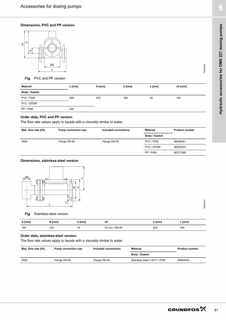
Dimensions, PVC and PP version
L
ØD
ah
H
TM03
8639
Fig. PVC and PP version
Material L [mm] H [mm] h [mm] a [mm] ⌀D [mm]
Body / Gasket
PVC / FKM 266 230 195 46 130
PVC / EPDM
PP / FKM 326
Order data, PVC and PP versionThe flow rate values apply to liquids with a viscosity similar to water.
Max. flow rate [l/h] Pump connection size Included connections Material Product number
Body / Gasket
4000 Flange DN 65 Flange DN 65 PVC / FKM 96638461
PVC / EPDM 96635243
PP / FKM 96727368
Dimensions, stainless-steel version
L
Ah
C
ØD
B
TM06
8749
Fig. Stainless-steel version
A [mm] B [mm] C [mm] ⌀D h [mm] L [mm]
185 145 18 76 mm / DN 65 203 394
Order data, stainless-steel versionThe flow rate values apply to liquids with a viscosity similar to water.
Max. flow rate [l/h] Pump connection size Included connections Material Product number
Body / Gasket
4000 Flange DN 65 Flange DN 65 Stainless steel 1.4571 / FKM 96694452
Accessories for dosing pumps 6
81
Hyd
raul
ic a
cces
sorie
s fo
r DM
X 22
7 do
sing
pum
ps

Pressure loading valves for DMX 227Pressure loading valves DN 65 are used, if the injection point is at a lower level than the pump.The opening pressure can be adjusted by a spring-loaded screw.Loading pressure: factory-set to 3 bar approximately
Dimensions
H
h
L
ØD
TM03
8638
Fig. Pressure loading valve
Material L [mm] H [mm] h [mm] ⌀D [mm]
Body Gasket
PP FKM 326 230 195 130
PVC FKM 266 230 195 130
PVC EPDM 266 230 195 130
Stainless steel 1.4571 FKM 280 243 203 198
Order dataThe flow rate values apply to liquids with a viscosity similar to water.
Max. flow rate [l/h] Pump connection size Included connections Material Product number
Body Gasket
4000 Flange DN 65 Flange DN 65 PP FKM 96727367
PVC FKM 96638486
PVC EPDM 96635246
Stainless steel 1.4571 FKM 96694434
Pulsation dampers DB and DBG for DMX 227Pulsation dampers DB and DBG have a separating diaphragm and are intended for the outlet side of the dosing pump.We recommend using one pulsation damper per dosing pump.Preload pressure: 2.7 bar.The delivery includes:
• Material for wall mounting
• Pulsation dampers DBG include a pressure gauge.
Accessories for dosing pumps6
82
Hydraulic accessories for D
MX 227 dosing pum
ps
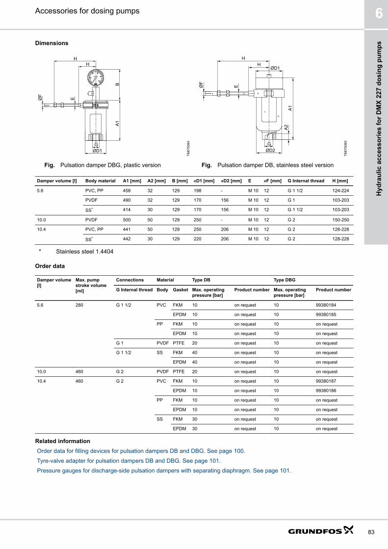
Dimensions
A1
B
HH
EØF
ØD1G
TM07
0064
Fig. Pulsation damper DBG, plastic version
ØD2G
A2
A1
ØD1H
H
EØF
TM07
0065
Fig. Pulsation damper DB, stainless steel version
Damper volume [l] Body material A1 [mm] A2 [mm] B [mm] ⌀D1 [mm] ⌀D2 [mm] E ⌀F [mm] G Internal thread H [mm]
5.6 PVC, PP 458 32 129 198 - M 10 12 G 1 1/2 124-224
PVDF 490 32 129 170 156 M 10 12 G 1 103-203
SS* 414 30 129 170 156 M 10 12 G 1 1/2 103-203
10.0 PVDF 500 50 129 250 - M 10 12 G 2 150-250
10.4 PVC, PP 441 50 129 250 206 M 10 12 G 2 128-228
SS* 442 30 129 220 206 M 10 12 G 2 128-228
* Stainless steel 1.4404
Order data
Damper volume[l]
Max. pumpstroke volume[ml]
Connections Material Type DB Type DBG
G Internal thread Body Gasket Max. operatingpressure [bar]
Product number Max. operatingpressure [bar]
Product number
5.6 280 G 1 1/2 PVC FKM 10 on request 10 99380184
EPDM 10 on request 10 99380185
PP FKM 10 on request 10 on request
EPDM 10 on request 10 on request
G 1 PVDF PTFE 20 on request 10 on request
G 1 1/2 SS FKM 40 on request 10 on request
EPDM 40 on request 10 on request
10.0 460 G 2 PVDF PTFE 20 on request 10 on request
10.4 460 G 2 PVC FKM 10 on request 10 99380187
EPDM 10 on request 10 99380186
PP FKM 10 on request 10 on request
EPDM 10 on request 10 on request
SS FKM 30 on request 10 on request
EPDM 30 on request 10 on request
Related informationOrder data for filling devices for pulsation dampers DB and DBG. See page 100.
Tyre-valve adapter for pulsation dampers DB and DBG. See page 101.
Pressure gauges for discharge-side pulsation dampers with separating diaphragm. See page 101.
Accessories for dosing pumps 6
83
Hyd
raul
ic a
cces
sorie
s fo
r DM
X 22
7 do
sing
pum
ps

Pump connection kits and inlay kits for DMX 227Retrofit pump connection kits and inlay kits for the integration of Grundfos standard pumps into installations with varioussizes of pipes.The connection kits are used to connect dosing pumps to pipes that differ from Grundfos standard sizes.
Pump connection size Pipe internal / external diameter [mm] Max. pressure [bar] Material Product number
Flange DN 65 65 / 75 10 PP 96727603
PVC 96727602
Stainless steel 1.4401 96727604
Accessories for dosing pumps6
84
Hydraulic accessories for D
MX 227 dosing pum
ps
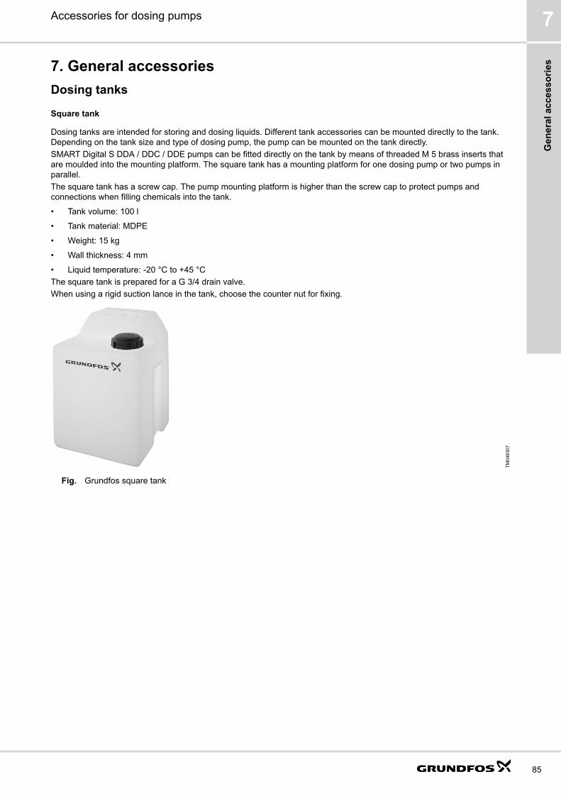
7. General accessoriesDosing tanks
Square tank
Dosing tanks are intended for storing and dosing liquids. Different tank accessories can be mounted directly to the tank.Depending on the tank size and type of dosing pump, the pump can be mounted on the tank directly.SMART Digital S DDA / DDC / DDE pumps can be fitted directly on the tank by means of threaded M 5 brass inserts thatare moulded into the mounting platform. The square tank has a mounting platform for one dosing pump or two pumps inparallel.The square tank has a screw cap. The pump mounting platform is higher than the screw cap to protect pumps andconnections when filling chemicals into the tank.
• Tank volume: 100 l
• Tank material: MDPE
• Weight: 15 kg
• Wall thickness: 4 mm
• Liquid temperature: -20 °C to +45 °CThe square tank is prepared for a G 3/4 drain valve.When using a rigid suction lance in the tank, choose the counter nut for fixing.
TM04
8307
Fig. Grundfos square tank
Accessories for dosing pumps 7
85
Gen
eral
acc
esso
ries

Dimensions of square tank
S1
D1
H2
A
H1
L1
L1
L1
W1W2
B
TM06
9772
H1 [mm] H2 [mm] D1 [mm] A [mm] B [mm] L1 [mm] W1 [mm] W2 [mm] S1
670 540 ⌀152 500 500 98 137 192 M 5
Order data
Description Product number
Square tank, 100 litres 96489271
Cylindrical tanks
Dosing tanks are intended for storing and dosing liquids. Different tank accessories can be mounted directly to the tank.Depending on the tank size and type of dosing pump, the pump can be mounted on the tank directly or with an adapterplate.Cylindrical tanks are available transparent or black. They have a litre scale and a black screw cap.
• Tank volume: 40-1000 l
• Tank material: LLDPE, UV-stabilised
• Liquid temperature: -20 °C to +45 °CAll cylindrical tanks are prepared for a G 3/4 opening for a drain valve, and have a screw plug (PE / EPDM).The cylindrical tanks with volumes of 60, 100, 200, 300 and 500 litres include additionally:
• Threaded M 6 inserts for the direct assembly of a dosing pump.
• A G 2 opening for a rigid suction lance or a foot valve, closed with a screw plug
• Threaded M 6 inserts at the bottom part for floor mounting with a set of floor-mounting brackets.
• A flange for an electric stirrer with threaded insertsThe cylindrical tanks with volumes of 60, 100, 200, 300, 500 and 1000 litres can optionally be prepared for direct assemblyof an electric stirrer:
• With opening for electric stirrer (60-500 l).
• With opening and reinforced beam for holding an electric stirrer (1000 l).
Accessories for dosing pumps7
86
General accessories

TM04
8468
Fig. Cylindrical tank, 60 litres
Requirements and restrictions for mounting pumps directly on cylindrical tanks
Pump type Tank volume [l] Requirement / restriction
SMART Digital S DDA / DDC / DDE 40, 1000 Holes must be drilled on site. Use plastic screw kit 95730864 to fix the pump on the tank.
60, 100, 200,300, 500
Use screw kit 98159495.
SMART Digital XL DDA / DDE 40 Mounting is not possible due to the pump's dimensions or weight.
60, 100 Pump fits with screw kit 98159495, but exceeds the mounting area. Combination with electricmixer is not possible.
200, 300, 500 Use screw kit 98159495.
1000 Holes must be drilled on site. Use plastic screw kit 95730864 to fix the pump on the tank.
DMX 221 40, 1000 Holes must be drilled on site. Use plastic screw kit 95730864 to fix the pump on the tank.
60, 100, 200,300, 500
Use screw kit 98159495.
DMX 226DMH 251 / 252 / 253DMH 280 / 281
40 Mounting is not possible due to the pump's dimensions or weight.
60, 100 Pump fits with tank adaptor plate 99211241, but possibly exceeds the mounting area.Combination with electric mixer might not be possible. Observe the pump's maximum suction lift.
200, 300, 500 Use tank adapter plate 99211241. Observe the pump's maximum suction lift.
1000 Holes must be drilled on site. Plastic screws cannot be used due to the pump's weight. Observethe pump's maximum suction lift.
DME 375-10, DME 940-4DMH 254 / 255 / 257DMH 283 / 285 / 286 / 287 / 288DMX 227
40, 60, 100, 200,300, 500, 1000
Mounting is not possible due to the pump's dimensions or weight.
Accessories for dosing pumps 7
87
Gen
eral
acc
esso
ries

Dimensions of cylindrical tank, 40 litres
C1
D1
H1
H2
H3
D2
D1
TM06
9773
H1 [mm] H2 [mm] H3 [mm] D1 [mm] D2 [mm] C1
420 350 45 ⌀160 ⌀420 Rp 3/4
Dimensions of cylindrical tank, 60 and 100 litres
C1
S4
S2
S3
C2
H2 H
1
H5
H4
H3
D2
D3
D4
D5
D1
W1
L1 L2
TM06
9774
Tank volume: 60 l Tank volume: 100 l
H1 [mm] H2 [mm] H1 [mm] H2 [mm]
590 545 840 795
Accessories for dosing pumps7
88
General accessories

H3 [mm] H4 [mm] H5 [mm] D1 [mm] D2 [mm] D3 [mm] D4 [mm] D5 [mm]
50 40 150 ⌀160 ⌀460 ⌀95 ⌀35 ⌀130
C1 C2 L1 [mm] L2 [mm] W1 [mm] S2 S3 S4
G 3/4 G 2 159 174 105 M 6 x 9 M 8 x 12 M 6 x 9
Dimensions of cylindrical tank, 200 and 300 litres
C1
S4
S2
S3
C2
H2 H1
H5
H4
H3
D2
D3
D4
D5
W1
L1 L2
D1
TM06
9775
Tank volume: 200 l Tank volume: 300 l
H1 [mm] H2 [mm] H1 [mm] H2 [mm]
810 770 1080 1040
H3 [mm] H4 [mm] H5 [mm] D1 [mm] D2 [mm] D3 [mm] D4 [mm] D5 [mm]
50 40 150 ⌀160 ⌀670 ⌀115 ⌀35 ⌀130
C1 [mm] C2 L1 [mm] L2 [mm] W1 [mm] S2 S3 S4
G 3/4 G 2 159 174 105 M 6 x 9 M 8 x 12 M 6 x 9
Accessories for dosing pumps 7
89
Gen
eral
acc
esso
ries

Dimensions of cylindrical tank, 500 litres
S2
S3
S4
C2
C1
D1
H2 H1
H5
H4
H3
D2
D3
D4
D5
W1
L1 L2
TM06
9776
H1 [mm] H2 [mm] H3 [mm] H4 [mm] H5 [mm] D1 [mm] D2 [mm] D3 [mm] D4 [mm] D5 [mm]
1235 1175 50 40 150 ⌀160 ⌀790 ⌀115 ⌀35 ⌀130
C1 C2 L1 [mm] L2 [mm] W1 [mm] S2 S3 S4
G 3/4 G 2 159 174 105 M 6 x 9 M 8 x 12 M 6 x 9
Accessories for dosing pumps7
90
General accessories

Dimensions of cylindrical tank, 1000 litres
C1
H1
H2
D1
D2
H3
TM06
9777
H1 [mm] H2 [mm] H3 [mm] D1 [mm] D2 [mm] C1
1260 1150 50 ⌀160 ⌀1080 G 3/4
Order data
Tank volume [l] Prepared for directassembly of an electricstirrer
Weight [kg] Product number
Transparent Black
40 - 3.4 96688081 95701166
60 - 5.5 98148805 98149053
Yes 5.5 98150038 98150040
100 - 7.5 98149057 98149082
Yes 7.5 98150051 98150052
200 - 11.5 98149215 98149224
Yes 11.5 98150053 98150054
300 - 13 98149245 98149252
Yes 13 98150055 98150056
500 - 28 98149266 98149269
Yes 28 98150057 98150058
1000 - 40 96688086 95706305
Yes 48 98173675 98173752
Related informationTank accessories. See page 92.
Pump mounting accessories. See page 99.
Accessories for dosing pumps 7
91
Gen
eral
acc
esso
ries
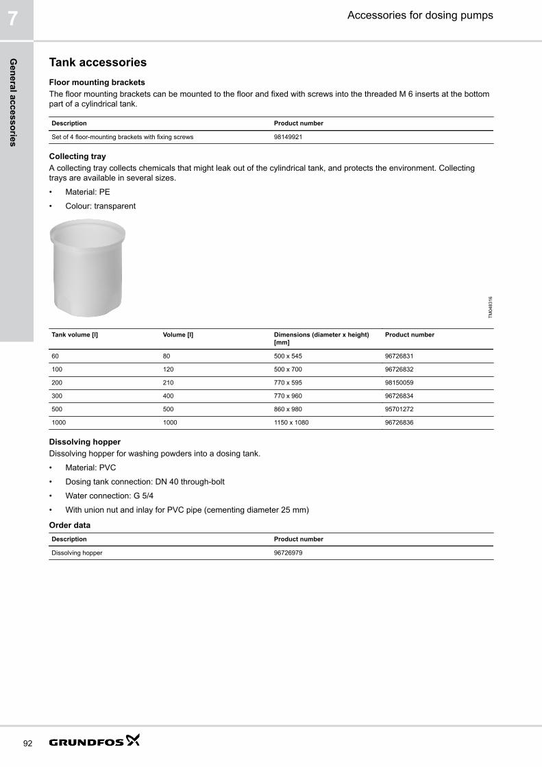
Tank accessoriesFloor mounting bracketsThe floor mounting brackets can be mounted to the floor and fixed with screws into the threaded M 6 inserts at the bottompart of a cylindrical tank.
Description Product number
Set of 4 floor-mounting brackets with fixing screws 98149921
Collecting trayA collecting tray collects chemicals that might leak out of the cylindrical tank, and protects the environment. Collectingtrays are available in several sizes.
• Material: PE
• Colour: transparent
TM04
8316
Tank volume [l] Volume [l] Dimensions (diameter x height)[mm]
Product number
60 80 500 x 545 96726831
100 120 500 x 700 96726832
200 210 770 x 595 98150059
300 400 770 x 960 96726834
500 500 860 x 980 95701272
1000 1000 1150 x 1080 96726836
Dissolving hopperDissolving hopper for washing powders into a dosing tank.
• Material: PVC
• Dosing tank connection: DN 40 through-bolt
• Water connection: G 5/4
• With union nut and inlay for PVC pipe (cementing diameter 25 mm)
Order dataDescription Product number
Dissolving hopper 96726979
Accessories for dosing pumps7
92
General accessories

Dimensions of dissolving hopper
AB
D
C
E
TM06
9778
A [mm] B [mm] C [mm] D [mm] E [mm]
⌀270 ⌀140 283 ⌀70 120
Handheld mixerHandheld mixer for use in dosing tanks.
• Material: PE
• Shaft length 1200 mm, length can be adapted to the corresponding dosing tank
• With DN 15 through-bolt for connection in the dosing tank
TM04
8477
Description Product number
Handheld mixer 98133793
Drain valveDrain valve for installation in the threaded sleeve of the dosing tank.
• Material: PVC
• Dosing tank connection: G 3/4
Description Product number
Drain valve 96689132
Accessories for dosing pumps 7
93
Gen
eral
acc
esso
ries

Ventilation valveThe spring-loaded ventilation valve can be installed either for aeration or deaeration of the dosing tank.Opening pressure: 0.05 bar
Description Material Product number
Body Gasket Ball
Ventilation valve PVC FKM Glass 96694401
Withdrawal deviceThe withdrawal device with ball valve is designed for installation in the drain opening of a Grundfos tank. Withdrawaldevices have a through-bolt for connection to the dosing tank.Hose or pipe connection sets are included.
• Hose connection set G 5/8: 4/6 mm, 6/9 mm, 6/12 mm and 9/12 mm
• Hose and pipe connection set G 5/4:
• for hoses with internal diameter 19 or 20 mm
• for pipes with external diameter 25 mm
Order data of withdrawal deviceThe flow rate values apply to liquids with a viscosity similar to water.
Size Max. flow rate [l/h] Material Product number
Body Gasket
G 5/8 60 PVC FKM 99226879
G 5/8 60 PVC EPDM 99226880
G 5/4 460 PVC FKM 99226881
G 5/4 460 PVC EPDM 99226893
Dimensions of withdrawal device
G
A
F
B
C
ED
TM06
8414
Size A [mm] B [mm] C D [mm] E [mm] F [mm] G
G 5/8 143 14 G 3/4 41 27 75 G 5/8
G 5/4 151 14 G 3/4 41 30 87 G 5/4
Electric stirrers
Electric stirrers are intended for the mixing and dissolving of non-abrasive, non-inflammable and non-explosive liquids.They ensure that the liquid in the dosing tank is mixed constantly. With a frequency of 50 Hz they run at approximately1500 rpm. Various types for tanks from 60 litres up to 1000 litres are available. Electric stirrers are suitable for liquids withlow to medium viscosity.The following types of electric stirrers are available:
• Stainless steel version (SS)
• PP-coated stainless steel version (PP)
• PP-coated stainless steel version with sealing flange (PP-S)
Accessories for dosing pumps7
94
General accessories

Order dataType Product number
Tank volume [l] Nominal shaft length [mm] Material Single-phase motor Three-phase motor
60 450 SS 98164569 98165309
PP 98164573 98165310
PP-S 98164575 98165318
100 690 SS 98164606 98165355
PP 98164607 98165357
PP-S 98164609 98165382
200 700 SS 98164987 98165385
PP 98164990 98165386
PP-S 98165152 98165391
300 950 SS 98165172 98165393
PP 98165175 98165432
PP-S 98165177 98165433
500 1100 SS 98165253 98165435
PP 98165258 98165436
PP-S 98165259 98165437
1000 1150 SS 98165287 98165439
PP 98165290 98165440
PP-S 98165304 98165451
Dimensions
I
D
AL (
SS
)P
BC
F
E
TM06
9780
Fig. Electric stirrer, stainless steel version
Tank volume[l]
L(SS)
[mm]A [mm] B [mm] C [mm] D [mm] E [mm] F [mm] P [mm] I [mm]
60 450 210 140 115 88 9 95 25 16
100 691 210 140 115 88 9 95 25 16
200 698 191 160 130 100 9 110 25 16
300 950 191 160 130 100 9 110 25 16
500 1100 191 160 130 125 9 110 28 16
1000 1150 231 200 165 125 11 130 28 16
Accessories for dosing pumps 7
95
Gen
eral
acc
esso
ries
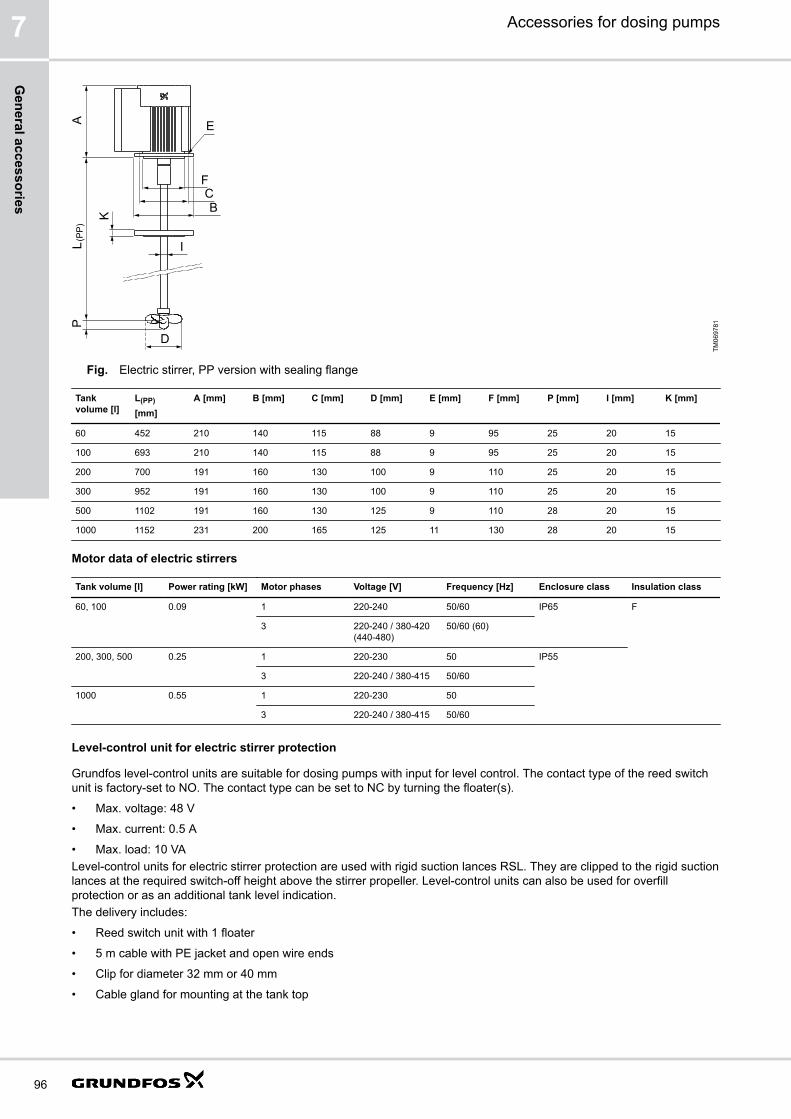
I
D
PL (
PP
)A
K
FCB
E
TM06
9781
Fig. Electric stirrer, PP version with sealing flange
Tankvolume [l]
L(PP)
[mm]A [mm] B [mm] C [mm] D [mm] E [mm] F [mm] P [mm] I [mm] K [mm]
60 452 210 140 115 88 9 95 25 20 15
100 693 210 140 115 88 9 95 25 20 15
200 700 191 160 130 100 9 110 25 20 15
300 952 191 160 130 100 9 110 25 20 15
500 1102 191 160 130 125 9 110 28 20 15
1000 1152 231 200 165 125 11 130 28 20 15
Motor data of electric stirrers
Tank volume [l] Power rating [kW] Motor phases Voltage [V] Frequency [Hz] Enclosure class Insulation class
60, 100 0.09 1 220-240 50/60 IP65 F
3 220-240 / 380-420(440-480)
50/60 (60)
200, 300, 500 0.25 1 220-230 50 IP55
3 220-240 / 380-415 50/60
1000 0.55 1 220-230 50
3 220-240 / 380-415 50/60
Level-control unit for electric stirrer protection
Grundfos level-control units are suitable for dosing pumps with input for level control. The contact type of the reed switchunit is factory-set to NO. The contact type can be set to NC by turning the floater(s).
• Max. voltage: 48 V
• Max. current: 0.5 A
• Max. load: 10 VALevel-control units for electric stirrer protection are used with rigid suction lances RSL. They are clipped to the rigid suctionlances at the required switch-off height above the stirrer propeller. Level-control units can also be used for overfillprotection or as an additional tank level indication.The delivery includes:
• Reed switch unit with 1 floater
• 5 m cable with PE jacket and open wire ends
• Clip for diameter 32 mm or 40 mm
• Cable gland for mounting at the tank top
Accessories for dosing pumps7
96
General accessories

Dimensions
F
E
ØAB
ØC
D
TM06
8304
Fig. Level-control unit for electric stirrer protection
⌀A [mm] B [mm] ⌀C [mm] D [mm] E [mm] F
40 47.5 32 20 182 M 12 x 1.5
32 43 32 28 190 M 12 x 1.5
Order data
Description Material For RSL with connectionsize
⌀A [mm] Product number
Level-control unit for electricstirrer protection
PE G 5/8 32 98306210
G 5/4, G 2 40 99174140
Flexible level-control unit
Grundfos level-control units are suitable for dosing pumps with input for level control. The contact type of the reed switchunit is factory-set to NO. The contact type can be set to NC by turning the floater(s).
• Max. voltage: 48 V
• Max. current: 0.5 A
• Max. load: 10 VAThe flexible level-control unit is suitable for dosing pumps with level-control input and provides 2 level switches.The delivery includes:
• Reed switch unit with 2 floaters
• 5 m of cable with PE jacket and M 12 plug
• Weight that keeps the level-control unit in an upright position at the tank bottom
• PE cap, ⌀58 mm, for assembly in Grundfos cylindrical tanks, or for use with tank adapters
Accessories for dosing pumps 7
97
Gen
eral
acc
esso
ries

Dimensions
JI
H
ØGF
ED
CBØA
TM06
8102
Fig. Flexible level control unit
⌀A [mm] B [mm] C [mm] D [mm] E [mm] F ⌀G [mm] H [mm] I [mm] J [mm]
35 19 43.5 103.5 196 G 5/8 58 6 9 12
Order data
Description Material Product number
Flexible level-control unit PE PE 98375695
Level-control units for RSL and FV for pump connection size G 2
Grundfos level-control units are suitable for dosing pumps with input for level control. The contact type of the reed switchunit is factory-set to NO. The contact type can be set to NC by turning the floater(s).
• Max. voltage: 48 V
• Max. current: 0.5 A
• Max. load: 10 VALevel-control units for RSL G 2 and FV G 2 are used for rigid suction lances or foot valves in stationary tanks for pumps upto 1150 l/h. They are clipped to the rigid suction lances or foot valves at the required switch-off height.The delivery includes:
• Reed switch unit with 2 floaters
• 5 m cable with PE jacket and M 12 plug
• Clip for diameter 40 mm
• Cable gland for mounting at the tank top
Accessories for dosing pumps7
98
General accessories
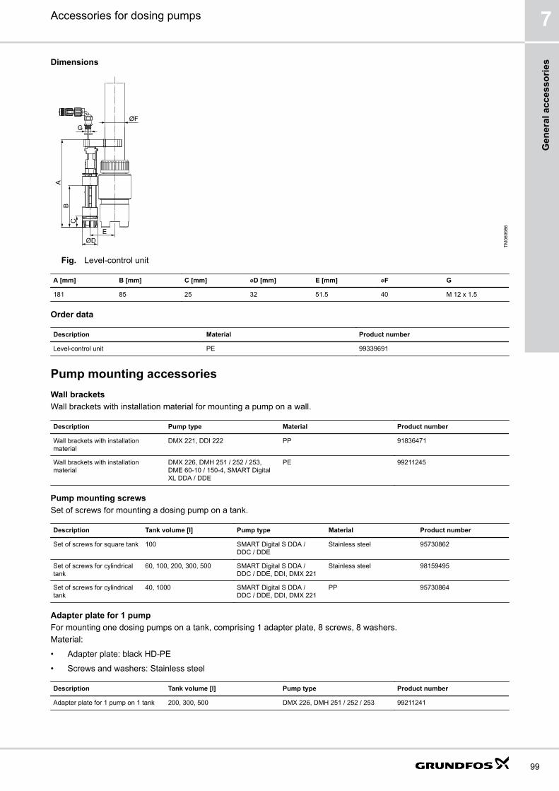
DimensionsA
BC
EØD
GØF
TM06
9986
Fig. Level-control unit
A [mm] B [mm] C [mm] ⌀D [mm] E [mm] ⌀F G
181 85 25 32 51.5 40 M 12 x 1.5
Order data
Description Material Product number
Level-control unit PE 99339691
Pump mounting accessoriesWall bracketsWall brackets with installation material for mounting a pump on a wall.
Description Pump type Material Product number
Wall brackets with installationmaterial
DMX 221, DDI 222 PP 91836471
Wall brackets with installationmaterial
DMX 226, DMH 251 / 252 / 253,DME 60-10 / 150-4, SMART DigitalXL DDA / DDE
PE 99211245
Pump mounting screwsSet of screws for mounting a dosing pump on a tank.
Description Tank volume [l] Pump type Material Product number
Set of screws for square tank 100 SMART Digital S DDA /DDC / DDE
Stainless steel 95730862
Set of screws for cylindricaltank
60, 100, 200, 300, 500 SMART Digital S DDA /DDC / DDE, DDI, DMX 221
Stainless steel 98159495
Set of screws for cylindricaltank
40, 1000 SMART Digital S DDA /DDC / DDE, DDI, DMX 221
PP 95730864
Adapter plate for 1 pumpFor mounting one dosing pumps on a tank, comprising 1 adapter plate, 8 screws, 8 washers.Material:
• Adapter plate: black HD-PE
• Screws and washers: Stainless steel
Description Tank volume [l] Pump type Product number
Adapter plate for 1 pump on 1 tank 200, 300, 500 DMX 226, DMH 251 / 252 / 253 99211241
Accessories for dosing pumps 7
99
Gen
eral
acc
esso
ries

Adapter plate for 2 pumpsFor mounting two dosing pumps on one tank, comprising 1 adapter plate, 12 screws, 12 washers.Material:
• Adapter plate: black HD-PE
• Screws and washers: Stainless steel
Description Tank volume [l] Pump type Product number
Adapter plate for 2 pumps on 1 tank 60, 100, 200, 300, 500 SMART Digital S DDA / DDC / DDE,DDI, DMX 221
98982080
Accessories for pulsation dampers and calibration columns
Filling devices for pulsation dampers DB and DBGFilling devices make the adjustment of the preload pressure of pulsation dampers easy. A filling device can be connectedto the filling valve of a pulsation damper and to a local compressed-air source or a nitrogen bottle. When the pressure isadjusted, the filling device can be removed.
Order data for filling devices for pulsation dampers DB and DBG
Filling devices are available with different pressure gauges.A set includes a filling device with pressure gauge and a hose with connections for a nitrogen bottle.Hose connections:
• Nitrogen bottle: W24.3 x 1 1/4"
• Filling device: G 1/4
TM07
0019
Fig. Filling device
Description Height [mm] Max. operating pressure [bar] Product number
Filling device with hose 136 25 96727342
60 96727343
160 96727344
250 96727345
Accessories for dosing pumps7
100
General accessories

Tyre-valve adapter for pulsation dampers DB and DBG
A tyre-valve adapter allows the use of a common air pump with tyre valve connector for filling pulsation dampers DB andDBG with air.
Dimensions
AB
C
D
TM06
9619
Fig. Tyre-valve adapter
A [mm] B C [mm] D [mm]
25 G 1/4 38 Vg 8
Order data
Description Max. operating pressure [bar] Product number
Tyre-valve adapter, for use in conjunction with compressed-air filling device or pressure gauge 8 96727332
Pressure gauges for discharge-side pulsation dampers with separating diaphragm
The following pressure gauges suit all sizes of discharge-side pulsation dampers with separating diaphragm. Select yoursuitable variant according to the maximum pressure of the pulsation damper.
Description Max. pressure[bar] Product number
Pressure gauge for discharge-side pulsation damper with separating diaphragm 10 95730263
25 95730264
60 98031543
160 98031544
250 98031545
Manual vacuum pump kit for pulsation damper CSD
In installations without flooded suction, the pulsation damper CSD can be filled by the manual vacuum pump kit. Thismakes startup of the dosing pump easier and prepares the pulsation damper CSD for calibration of the pump.The delivery includes:
• Ball valve, connection G 5/8
• T-piece, connection G 5/8
• Hose
• Manual vacuum pump
• Holder for wall mountingMaterials:
• Vacuum pump: PVC
• Ball valve and T-piece: PVC
• Gasket: FKM
Accessories for dosing pumps 7
101
Gen
eral
acc
esso
ries

TM06
8426
Fig. Manual vacuum pump kit
Dimensions
AB
C
GEØ
F
D
TM06
9603
Fig. Manual vacuum pump kit
A [mm] B [mm] C [mm] D [mm] E [mm] ⌀F [mm] G [mm]
131 34 132.5 50 242 6.2 675-875
Order data
Description Product number
Manual vacuum pump kit 99218131
Manual vacuum pump kit for calibration columns
In installations without flooded suction, the calibration column can be filled by the manual vacuum pump kit. This makesstartup of the dosing pump easier and prepares the calibration column for pump calibration.The delivery includes:
• Ball valve, connection G 5/8
• T-piece, connection G 5/8
• Hose
• Manual vacuum pump
• Holder for wall mounting
Accessories for dosing pumps7
102
General accessories
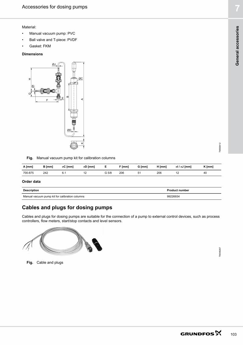
Material:
• Manual vacuum pump: PVC
• Ball valve and T-piece: PVDF
• Gasket: FKM
Dimensions
FE
GH
ØI
ØJ
ØD
A
B
ØCK
TM06
8412
Fig. Manual vacuum pump kit for calibration columns
A [mm] B [mm] ⌀C [mm] ⌀D [mm] E F [mm] G [mm] H [mm] ⌀I / ⌀J [mm] K [mm]
700-875 242 6.1 12 G 5/8 206 51 206 12 40
Order data
Description Product number
Manual vacuum pump kit for calibration columns 99226934
Cables and plugs for dosing pumpsCables and plugs for dosing pumps are suitable for the connection of a pump to external control devices, such as processcontrollers, flow meters, start/stop contacts and level sensors.
TM04
8267
Fig. Cable and plugs
Accessories for dosing pumps 7
103
Gen
eral
acc
esso
ries

Cables and plugs for pump connection size G 5/8
• Cable material: PVC, 0.34 mm2
• Plug size: M 12
Socket Application Pins Plug type Cable length [m] Product numberTM
0411
56 Input Analog, Pulse,External stop
4 Straight 2 96609014
5 96609016
No cable 96698715
Angled 2 96693246
TM04
1119 Input Low level, Empty
tank4 Straight No cable 96698715
TM04
1117 Input, Output GENIbus, Analog 5 Straight 2 96632921
5 96632922
No cable 96609031
Angled 2 96699697
TM04
1118 Output Relay 4 Straight 2 96609017
5 96609019
No cable 96696198
Angled 2 96698716
TM04
1156
TM04
1119
Extension cable Analog, Pulse,External stop, Lowlevel, Empty tank
4 Straight 2 96483235
Accessories for dosing pumps7
104
General accessories

Cables and plugs for pump connection size G 5/4
• Cable material: PVC, 0.34 mm2
• Plug size: M 12
Socket (DDA,DDE)
Socket (DMX, DMH, DDI) Application Pins Plug type Cable length[m]
Productnumber
TM04
1156 4 Input Analog, Pulse,
External stop4 Straight 2 96609014
5 96609016
No cable 96698715
Angled 2 96693246
TM04
1118 3 Output Relay 4 Straight 2 96609017
5 96609019
No cable 96696198
Angled 2 96698716
TM06
8403 2 Output Analog 5 Straight 2 96632921
5 96632922
No cable 96609031
Angled 2 96699697
TM04
1119 5 DDI Input Low level,
Empty tank4 Straight No cable 96698715
- 5 DMX / DMHAR
Input Low level,Empty tank
3 Straight, withsoldered cable
No cable 96630345
Adapter, flat-round
Low level,Empty tank
4 No cable 96635010
- 6 DDI Profibus Y-connector No cable 96693735
Terminatingresistor
No cable 96693737
TM06
8453 Input, Output GENIbus 5 Straight 3 98589048
TM04
1156
TM04
1119
4 / 5 Extensioncable
Analog, Pulse,External stop,Low level,Empty tank
4 Straight 2 96483235
- Mainsconnection forDDI, DDA,DDE
110-240 VAC 3 Angled No cable 96698717
Flat-plug adapter for DMX and DMH with AR control unit
The flat-plug adapter allows to connect rigid suction lances or foot valves with level indication to pumps with a level inputdesigned for flat plugs (e.g. DMX and DMH with AR control unit).
TM07
0206
Fig. Flat-plug adapter for DMX and DMH with AR control unit
Order data
Description Product number
Flat-plug adapter for DMX and DMH with AR control unit 96635010
Accessories for dosing pumps 7
105
Gen
eral
acc
esso
ries

Cables and plugs for DME pumps
• Cable material: PUR, 0.34 mm2
• Plug size: M 12
Socket Application Pins Plug type Cable length [m] Product numberTM
0411
56 Input Analog, Pulse,Diaphragm leakage
5 Straight 2 96440447
5 96440448
No cable 96440449
TM04
1119 Input Low level, Empty
tank4 Straight 2 96440450
5 96440451
No cable 96440452
TM04
1117 Input, Output External stop,
Dosing output5 Straight 2 96527109
5 96527111
No cable 96606401
- Output Relay 3 Straight 2 96534214
5 96534215
TM04
1119 Extension cable:
Low level, Emptytank
4 Straight 2 96483235
E-box for SMART Digital S DDAThe Grundfos E-box (Extension Box) is a Plug & Play fieldbus communication interface for the integration of SMARTDigital S DDA dosing pumps (up to 30 l/h) into a fieldbus network. Fieldbus communication allows to use the DDA dosingpump in industrial automation systems (PLC; SCADA), where advanced remote control and monitoring functions arerequired:
• Remote control of all settings, such as operation mode, flow rate, etc.
• Remote monitoring of all parameters, such as measured flow, pressure, faults with cause, etc.The E-box contains a standard Grundfos CIM communication interface module for data transmission between a fieldbusnetwork and a Grundfos pump.SMART Digital S DDA dosing pumps can be retrofitted easily with the E-box: it is simply placed between the pump and themounting plate. The E-box has a connecting cable that is plugged directly into the pump.
TM04
8455
Fig. E-Box
Accessories for dosing pumps7
106
General accessories
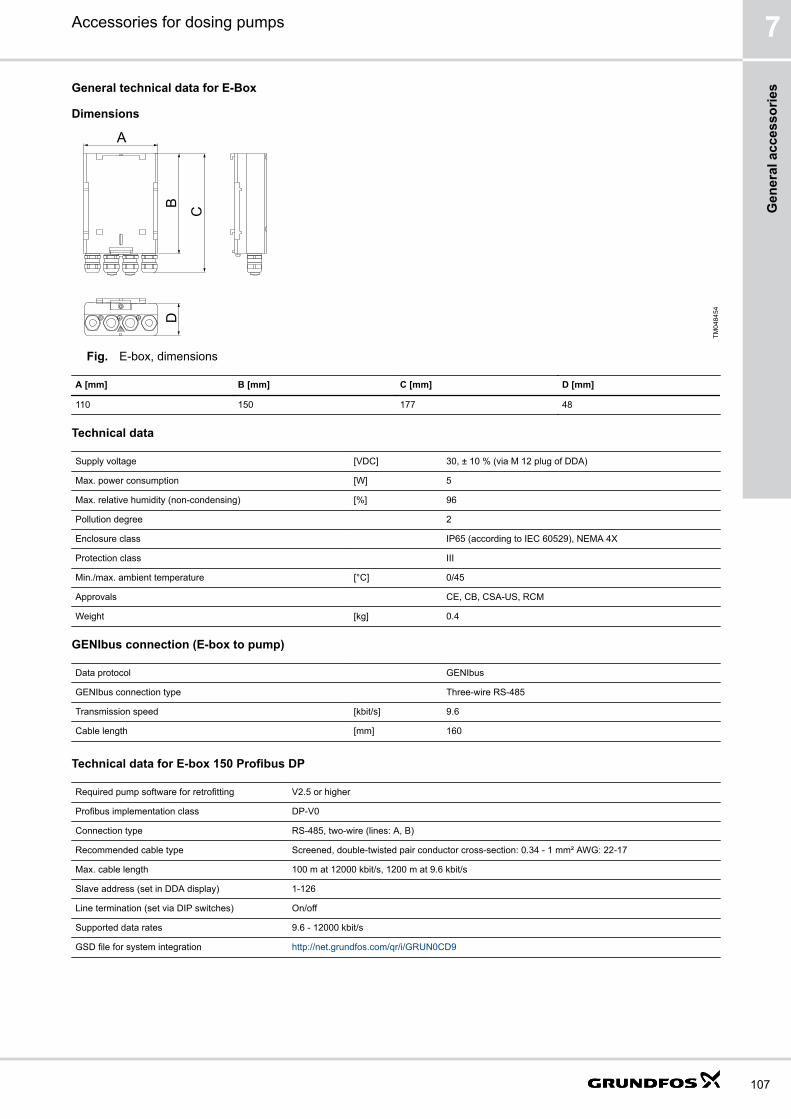
General technical data for E-Box
Dimensions
A
BD
C
TM04
8454
Fig. E-box, dimensions
A [mm] B [mm] C [mm] D [mm]
110 150 177 48
Technical data
Supply voltage [VDC] 30, ± 10 % (via M 12 plug of DDA)
Max. power consumption [W] 5
Max. relative humidity (non-condensing) [%] 96
Pollution degree 2
Enclosure class IP65 (according to IEC 60529), NEMA 4X
Protection class III
Min./max. ambient temperature [°C] 0/45
Approvals CE, CB, CSA-US, RCM
Weight [kg] 0.4
GENIbus connection (E-box to pump)
Data protocol GENIbus
GENIbus connection type Three-wire RS-485
Transmission speed [kbit/s] 9.6
Cable length [mm] 160
Technical data for E-box 150 Profibus DP
Required pump software for retrofitting V2.5 or higher
Profibus implementation class DP-V0
Connection type RS-485, two-wire (lines: A, B)
Recommended cable type Screened, double-twisted pair conductor cross-section: 0.34 - 1 mm² AWG: 22-17
Max. cable length 100 m at 12000 kbit/s, 1200 m at 9.6 kbit/s
Slave address (set in DDA display) 1-126
Line termination (set via DIP switches) On/off
Supported data rates 9.6 - 12000 kbit/s
GSD file for system integration http://net.grundfos.com/qr/i/GRUN0CD9
Accessories for dosing pumps 7
107
Gen
eral
acc
esso
ries

Technical data for E-box 200 Modbus RTU
Required pump software for retrofitting V2.5 or higher
Connection type RS-485, two-wire + common
Recommended cable type Screened, twisted pair conductor cross-section: 0.20 - 0.25 mm² AWG: 24-23
Max. cable length 1200 m
Slave address (set in DDA display) 1-247
Line termination (set via DIP switches) On/off
Supported data rates 9600 / 19200 / 38400 bit/s
Technical data for E-box 500 Ethernet
Required pump software for retrofitting V2.5 or higher
Ethernet protocol PROFINET IO / Modbus TCP (selected via rotary switch)
Application layer DHCP, HTTP, Ping, FTP, SMTP, SNTP, Modbus TCP
Transport layer TCP
Internet layer Internet protocol V4 (IPv4)
Link layer ARP, media access control (Ethernet)
Recommended cable type Screened/unscreened, twisted-pair cables, CAT5, CAT5e or CAT6
Order data for E-box
Description Product number
E-box 150 Profibus DP 97513994
E-box 200 Modbus RTU 98563350
E-box 500 Ethernet 99171932
Water metersThe in-line water meter with potential-free pulse signal is suitable for use in flow-proportional dosing applications. If thewater meter is connected directly to the pump pulse input, use a control plug (product number 96698715).
• Qn 1.5 and Qn 2.5 water meters are of the multi-jet, dry dial type, for cold water up to 30 °C, or hot water up to 90 °C.
• Qn 15 water meters and up are of the helical vane type, for cold water up to 30 °C or 50 °C, or hot water up to 90 °Cor 120 °C.
• Qn 1.5 to Qn 15 water meters:
• Threaded connections
• Cable length: 3 m
• Max. pressure: 16 bar
• Maximum load, Reed contact: 30 VAC/VDC, 0.2 A
• Qn 40 to Qn 150 water meters:
• Flange connections
• Cable length: 3 m
• Max. pressure: 10 bar
• Maximum load, Namur contact: 8-12 VDC, 1 kOhm (requires external power supply)
Accessories for dosing pumps7
108
General accessories
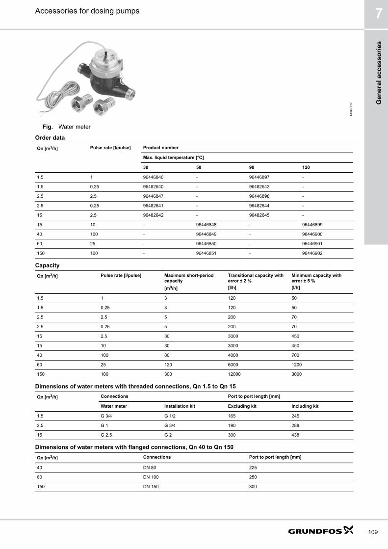
TM04
8317
Fig. Water meter
Order data
Qn [m3/h] Pulse rate [l/pulse] Product number
Max. liquid temperature [°C]
30 50 90 120
1.5 1 96446846 - 96446897 -
1.5 0.25 96482640 - 96482643 -
2.5 2.5 96446847 - 96446898 -
2.5 0.25 96482641 - 96482644 -
15 2.5 96482642 - 96482645 -
15 10 - 96446848 - 96446899
40 100 - 96446849 - 96446900
60 25 - 96446850 - 96446901
150 100 - 96446851 - 96446902
Capacity
Qn [m3/h] Pulse rate [l/pulse] Maximum short-periodcapacity[m3/h]
Transitional capacity witherror ± 2 %[l/h]
Minimum capacity witherror ± 5 %[l/h]
1.5 1 3 120 50
1.5 0.25 3 120 50
2.5 2.5 5 200 70
2.5 0.25 5 200 70
15 2.5 30 3000 450
15 10 30 3000 450
40 100 80 4000 700
60 25 120 6000 1200
150 100 300 12000 3000
Dimensions of water meters with threaded connections, Qn 1.5 to Qn 15
Qn [m3/h] Connections Port to port length [mm]
Water meter Installation kit Excluding kit Including kit
1.5 G 3/4 G 1/2 165 245
2.5 G 1 G 3/4 190 288
15 G 2.5 G 2 300 438
Dimensions of water meters with flanged connections, Qn 40 to Qn 150
Qn [m3/h] Connections Port to port length [mm]
40 DN 80 225
60 DN 100 250
150 DN 150 300
Accessories for dosing pumps 7
109
Gen
eral
acc
esso
ries
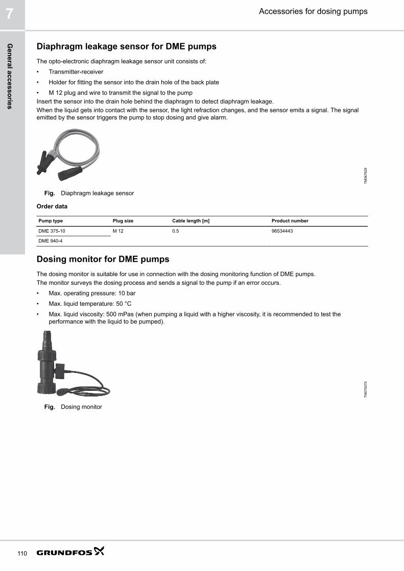
Diaphragm leakage sensor for DME pumpsThe opto-electronic diaphragm leakage sensor unit consists of:
• Transmitter-receiver
• Holder for fitting the sensor into the drain hole of the back plate
• M 12 plug and wire to transmit the signal to the pumpInsert the sensor into the drain hole behind the diaphragm to detect diaphragm leakage.When the liquid gets into contact with the sensor, the light refraction changes, and the sensor emits a signal. The signalemitted by the sensor triggers the pump to stop dosing and give alarm.
TM06
7629
Fig. Diaphragm leakage sensor
Order data
Pump type Plug size Cable length [m] Product number
DME 375-10 M 12 0.5 96534443
DME 940-4
Dosing monitor for DME pumpsThe dosing monitor is suitable for use in connection with the dosing monitoring function of DME pumps.The monitor surveys the dosing process and sends a signal to the pump if an error occurs.
• Max. operating pressure: 10 bar
• Max. liquid temperature: 50 °C
• Max. liquid viscosity: 500 mPas (when pumping a liquid with a higher viscosity, it is recommended to test theperformance with the liquid to be pumped).
TM07
0070
Fig. Dosing monitor
Accessories for dosing pumps7
110
General accessories

Dimensions
F
B
E
C
D
A
TM04
1536
Fig. Dimensions of dosing monitor
A [mm] B C D [mm] E [mm] F [mm]
140 G 2 G 2 56.5 62.5 950
Order data
Pump type Material Product number
Body Gasket
DME 375-10DME 940-4
PP EPDM 96655232
FKM 96655233
Accessories for dosing pumps 7
111
Gen
eral
acc
esso
ries

8. Grundfos Product CenterOnline search and sizing tool to help you make the right choice.http://product-selection.grundfos.com
All the information you need in one placePerformance curves, technical specifications, pictures, dimensionaldrawings, motor curves, wiring diagrams, spare parts, service kits, 3Ddrawings, documents, system parts. The Product Center displays anyrecent and saved items - including complete projects - right on the mainpage.DownloadsOn the product pages, you can download installation and operatinginstructions, data booklets, service instructions, etc. in PDF format.
TM07
0461
TM07
0462
Pos. Description
1 SIZING enables you to size a pump based on entered data and selection choices.
2 CATALOGUE gives you access to the Grundfos product catalogue.
3 REPLACEMENT enables you to find a replacement product.• Search results will include information on• the lowest purchase price• the lowest energy consumption• the lowest total life cycle cost.
4 LIQUIDS enables you to find pumps designed for aggressive, flammable or other special liquids.
Accessories for dosing pumps8
112
Grundfos Product C
enter

96700284 0218ECM: 1229256
The
nam
e G
rund
fos,
the
Gru
ndfo
s lo
go, a
nd b
e th
ink
inno
vate
are
regi
ster
ed tr
adem
arks
ow
ned
by G
rund
fos
Hol
ding
A/S
or G
rund
fos
A/S
, Den
mar
k. A
ll rig
hts
rese
rved
wor
ldw
ide.
© C
opyr
ight
Gru
ndfo
s H
oldi
ng A
/S