
Grundfos CU 300 Installation and Operating Instructions
52
CU 300 Installation and operating instructions GRUNDFOS INSTRUCTIONS No contact Overvoltage Undervoltage Dry running Speed reduction Overtemperature Overload Sensor alarm Other languages www.grundfos.com/CU300-manual
Transcript of Grundfos CU 300 Installation and Operating Instructions

CU 300Installation and operating instructions
GRUNDFOS INSTRUCTIONS
No contact
Overvoltage
Undervoltage
Dry running
Speed reduction
Overtemperature
Overload
Sensor alarm
Other languages
www.grundfos.com/CU300-manual

En
glish
(GB
)
2
English (GB) Installation and operating instructions
Original installation and operating instructions.
CONTENTSPage
1. Symbols used in this document 3
2. General 32.1 Expansion possibilities 32.2 On/Off button 3
3. Mechanical installation 43.1 Location 43.2 Mounting CU 300 4
4. CU 300 as an alarm unit 44.1 Description 44.2 Electrical installation 54.3 Description of dry-running protection 64.4 Settings 64.5 Description of the dewatering function 7
5. CU 300 with constant-pressure control - 0 to 6 bar 8
5.1 Description 85.2 Function 85.3 Positioning the pressure sensor 95.4 System sizing 95.5 Electrical installation 105.6 Startup 11
6. CU 300 with constant-pressure control - 0 to 10 bar 12
6.1 Description 126.2 Function 126.3 Positioning the pressure sensor 136.4 System sizing 136.5 Electrical installation 146.6 Startup 15
7. CU 300 with constant-pressure control - two-pump operation 16
7.1 Description 167.2 Function 167.3 Positioning the pressure sensor 177.4 System sizing 177.5 Electrical installation 187.6 Startup 19
8. CU 300 with sensors 208.1 General 208.2 Sensor functioning 218.3 Electrical installation 22
9. CU 300 connected to potentiometer 249.1 Description 249.2 Electrical installation 25
10. CU 300 connected to water meter 2610.1 Description 2610.2 Electrical installation 27
11. Constant water level 2811.1 Description 2811.2 Function 28
11.3 Electrical installation 29
12. CU 300 connected to RS-485 3112.1 Description 3112.2 CU 300 connected to a PC directly 3112.3 Electrical installation 32
13. Alarm functions 3413.1 No contact 3413.2 Overvoltage 3413.3 Undervoltage 3513.4 Dry running 3513.5 Speed reduction 3613.6 Overtemperature 3613.7 Overload 3713.8 Sensor alarm 37
14. CU 300 with Grundfos GO 3714.1 Menu overview 38
15. Description of functions 4015.1 Status 4015.2 Settings 4015.3 Alarms and warnings 45
16. Technical data 46
17. Disposal 47
Warning
Prior to installation, read these installation and operating instructions. Installation and operation must comply with local regulations and accepted codes of good practice.
Warning
This product can be used by children of eight years and up and persons with reduced physical, sensory or mental capabilities or lack of experience and knowledge if they are under supervision or have been instructed in the safe use of the product and understand the hazards involved.
Children must not play with the product. Cleaning and maintenance of the product must not be made by children without supervision.

En
glis
h (
GB
)
3
1. Symbols used in this document
2. GeneralThe control unit CU 300 is developed for the SQE submersible pumps.
CU 300 covers the voltage range 1 x 100-240 V - 10 %/+ 6 %, 50/60 Hz, PE.
CU 300 has the following functions:
• control of the pump on the basis of sensor signals
• setting of operating parameters
• monitoring of operation and alarm indication, if any.
CU 300 indicates the following alarms:
• no contact
• overvoltage
• undervoltage
• dry running
• speed reduction
• overtemperature
• overload
• sensor alarm.
The individual alarms are described in details in section 13. Alarm functions.
CU 300 receives alarm signals from the motor for the following parameters:
• dry running
• incipient pump or motor defect
• too high temperature in motor electronics
• supply failure.
As standard, CU 300 incorporates an alarm signal relay.
2.1 Expansion possibilities
CU 300 enables the use of the following devices:
• Grundfos GO: Wireless infra-red remote control that enables change of factory settings and monitoring of the installation by calling up actual operating data, e.g. speed, operating hours and power consumption.
• External sensors: Reception of data from external sensors and control according to the data received, e.g. flow rate, pressure, water level and conductivity.
• External potentiometer SPP 1:Manual speed control.
2.2 On/Off button
By means of the On/Off button on CU 300, you can do the following:
• Start or stop the pump.
• Reset alarms.
Fig. 1
The green and red indicator lights in the On/Off button indicate pump operating condition as follows:
* If you use the On/Off button to stop the pump, you must also use this button for restarting the pump.If you press the On/Off button for minimum 5 seconds, you start the pump, irrespective of any active fault or alarm indications. When you release the On/Off button, the pump will stop.
Warning
If these safety instructions are not observed, it may result in personal injury.
Note Notes or instructions that make the job easier and ensure safe operation.
TM
01
28
29
46
01
Indication Description
Green indicator light permanently on
Pump is operating
Green indicator light flashing
Pump has been stopped by one of the following:• a sensor
• an external on/off switch
• a stop command from the Grundfos GO
Red indicator light permanently on
Pump has been stopped by means of the On/Off button*
Red indicator light flashing
CU 300 is communicating with the Grundfos GO
Green
Red

En
glish
(GB
)
4
3. Mechanical installation
3.1 Location
You can place CU 300 both indoors and outdoors. The control unit must not be exposed to direct sunlight.
3.2 Mounting CU 300
CU 300 is designed for wall mounting.
The box has six mounting holes (∅4). See fig. 2. The dimensions are in mm.
CU 300 must be mounted as follows:
• Horizontally to allow condensed water, if any, to escape. See fig. 2.
• On a plane surface to avoid deformation of the box.
Fig. 2
CU 300 is supplied with a set of gaskets for the Pg screwed connections.
The gaskets are to be used for the connection of cables or wires to ensure tight connections, IP55, and cable relief.
4. CU 300 as an alarm unit
4.1 Description
When CU 300 is connected to an SQE pump, one of the eight red indicator lights on CU 300 will indicate any alarm.
The indications are based on signals from the motor and from sensors, if installed. The individual alarms are described in details in section 13. Alarm functions.
You can connect an external alarm-signal transmitter and an external on/off switch. See section 4.2 Electrical installation concerning connection, etc.
Figure 3 shows an example of an installation with CU 300 as an alarm unit.
Fig. 3
CU 300 functions as an alarm unit for the pump. Furthermore, you can communicate with the pump via the remote control Grundfos GO, see also section 14. CU 300 with Grundfos GO.
Warning
Before starting any work on CU 300, make sure that the power supply has been switched off and that it cannot be accidentally switched on.
TM
01
28
24
24
98
104.5104.5
100
140.5
TM
01
31
50
46
01

En
glis
h (
GB
)
5
4.2 Electrical installation
The supply voltage and frequency are marked on the nameplate. Make sure that CU 300 is suitable for the power supply on which it will be used.
Fig. 4
4.2.1 Mains supply
POWER, terminals 1, 2 and PE
Connect terminals 1 and 2 to the phase and neutral leads of the mains supply. You can connect each terminal to any of the two leads.
Connect the PE terminal to the green/yellow earth lead. You must connect each PE terminal to an earth lead of its own.
The maximum cross-section of the leads to be connected is 6 mm2.
Backup fuse: Maximum 16 A.
Warning
Never make any connections in the CU 300 unit unless the power supply has been switched off. CU 300 must be connected in accordance with the rules and standards in force for the application in question.
TM
01
30
67
33
98
K1
POWERPE
PUMP
RELAYALARM
CO
MN
C
NO
NO
NC
CO
M
AUXRELAY IN
DIG
IN+24V
DC
GN
D
GN
D
+24V
DC
IN
SENSOR1 2
SENSOR
IN+24V
DC
GN
D
RS485
RS232
B GN
DA R
ID
TRR
XD
GN
D
5 6 7
1 2
1098
3 4
111213 161514 171819
PE
TXD
LNL N
H S1
Pos. Description
S1 On/off switch for start or stop of pump
H Alarm signal transmitter (optional)
K1Internal alarm signal relayRelay data: 250 VAC, 1 A, AC1
Note You must not connect the leads of the mains supply to terminals 3 and 4.

En
glish
(GB
)
6
4.2.2 Pump supply
PUMP, terminals 3, 4 and PE
Connect terminals 3 and 4 to the phase and neutral leads of the pump. You can connect each terminal to any of the two leads.
Connect the PE terminal to the green/yellow earth lead. You must connect each PE terminal to an earth lead of its own.
The maximum cross-section of the leads to be connected is 6 mm2.
4.2.3 Alarm signal relay
ALARM RELAY, terminals 5, 6 and 7
Connect terminals 5, 6 and 7 to the internal alarm signal relay as follows:
• Terminal 5 NC (normally closed).
• Terminal 6 COM (common).
• Terminal 7 NO (normally open).
The relay is activated when the alarm and warning limits are exceeded.
You can select manual or automatic restarting in the Grundfos GO display "Automatic restarting".
Manual restarting is carried out by means of the On/Off button on CU 300.
4.2.4 Digital input
DIG IN, terminals 11, 12 and 13
In fig. 4, the digital input is used to start and stop the pump.
You can select the function of the digital input by means of the Grundfos GO in the display "Digital input".
4.3 Description of dry-running protection
When the pump sucks air, the pump power input decreases.
If the pump power input falls below the dry-running power limit set in the Grundfos GO display "Dry-running stop", the pump will stop and CU 300 will indicate the dry-running alarm.
4.3.1 Function
The dry-running protection applies only if the motor speed lies within the maximum speed range (i.e. maximum speed less than 1000 min-1). See fig. 5.
Normally, maximum speed is 10,700 min-1. However, you can reduce the maximum speed in the Grundfos GO display "Maximum speed". The dry-running power limit set in the display "Dry-running stop" must match the speed.
Changing the setpoint:
If you use the Grundfos GO display "Setpoint" or "External setpoint" to change the setpoint, the pump can be forced to run at a reduced speed in relation to the maximum speed. The dry-running protection will not protect the pump if the reduced speed lies outside the maximum speed range (i.e. maximum speed less 1000 min-1). See fig. 5.
Constant-pressure control
In constant-pressure control mode, the dry-running protection is active, as the motor will operate at maximum speed in connection with dry running.
Pump power input curve
The curve shows the pump power input in relation to the pump speed.
Fig. 5
4.4 Settings
For a detailed description of the Grundfos GO displays, see section 14. CU 300 with Grundfos GO.
4.4.1 Required Grundfos GO settings
If the maximum speed of the pump has been reduced by more than 1000 min-1, the dry-running stop value must be changed. In order to change the dry-running protection function, you must make the following Grundfos GO settings.
1. Set "Dry-running protection" to "Active".
Set the dry-running power limit in the display 15.2.21 Dry-running stop by following the procedure below:
– Start the pump against a closed discharge pipe.
– Read the input power (P1) in the display 15.1.9 Power consumption.
– Calculate the dry-running power limit: P1 x 0.9 [W].
– Set this value in the display 15.2.21 Dry-running stop.
TM
01
26
89
25
98
Note
In certain installations, it may be necessary to disable the dry-running protection. The disabling applies to the dry-running power limit set in the display 15.2.21 Dry-running stop. See fig. 5.
3000 min-1 Max. speed-1000 min-1
Max. speed as set in section 15.2.22
10,700 min-1
Motor speed
Watt
Pump power input Pump power curve
Dry-running power limit set

En
glis
h (
GB
)
7
4.5 Description of the dewatering function
When the pump sucks air, the pump power input decreases.
If the pump power input falls below the dry-running power limit set in the display 15.2.21 Dry-running stop, the pump will stop.
During dewatering, the green indicator light in the On/Off button on CU 300 is flashing to indicate that the pump has stopped.
4.5.1 Applications
You can use the dewatering function in applications where the pump often runs dry, e.g.:
• In boreholes with a low yield.
• In boreholes and building sites where the water table should be lowered.
4.5.2 Function
The dewatering function works as follows:
1. The pump is operating.
2. The pump sucks air due to a drop in the water level.
3. The load decreases, and consequently the pump power input does as well.
4. The pump stops when the power input falls to the dry-running power limit set in the Grundfos GO display 15.2.21 Dry-running stop.
4.5.3 Required Grundfos GO settings
In order to activate the dewatering function, you must make the following Grundfos GO settings:
1. Set "Dry-running protection" to "Active".
2. Set the dry-running power limit, i.e. dry-running stop. See "Setting of dry-running power limit (dry-running stop)" below.
3. Set the relation between run and stop times.Indication of operation:The dry-running alarm indication on CU 300 is automatically disabled, when you make the setting in the display 15.2.19 Dewatering, maximum "On" and "Off" time. To disable the dewatering function and return to dry-running protection, simply disable the "Dewatering" function in the display 15.2.18 Dewatering.
Setting of dry-running power limit (dry-running stop):
1. Start the pump against a closed discharge pipe.
2. Read the input power (P1) in the display 15.1.9 Power consumption.
3. Calculate the dry-running power limit: P1 x 0.9 [W].
4. Set this value in the display 15.2.21 Dry-running stop.
4.5.4 On/off times
The dewatering function means that there is a dependence between the period of time during which the pump is running, the on time, and the period of time during which the pump is stopped, the off time.
Figure 6 shows an example of on and off times set in the display 15.2.19 Dewatering, maximum "On" and "Off" time.
Fig. 6
Explanation:
The on and off times are set to 60 minutes each. The pump has been running for 25 minutes when dry running occurs. The pump will be stopped for 35 minutes. If the pump has been running for e.g. 120 minutes, the stop time will be 1 minute.
Note
The length of the stop time depends on the setting you have made in the Grundfos GO display "Dewatering max off time". See section 15.2.19 Dewatering, maximum "On" and "Off" time.
TM
06
35
01
04
15
35
1
1 25 60
60
Off time [minutes]
On time [minutes]

En
glish
(GB
)
8
5. CU 300 with constant-pressure control - 0 to 6 bar
5.1 Description
Using constant-pressure control enables automatic adjustment of the pump performance according to consumption. The system maintains a constant pressure within the maximum pump performance in spite of a varying water consumption.
Figure 7 shows an example of an installation with constant-pressure control within the range from 0 to 6 bar.
Fig. 7
5.2 Function
The pressure is registered by means of the pressure sensor, which transmits a signal to CU 300. CU 300 adjusts the pump performance accordingly by changing the pump speed.
Mains borne signalling
The communication between CU 300 and the pump is effected via the power supply cable.
This communication principle is called mains borne signalling or power line communication. Using this principle means that no additional cables to the pump are required.
The communication of data is effected by means of a high-frequency signal transmitted to the power supply cable and led into the electronics unit by means of signal coils incorporated in the motor and CU 300 respectively.
When does the pump start?
The pump starts as a consequence of:
• high flow
• low pressure
• a combination of both.
To ensure that the pump is started when water is consumed, a flow detection is required. The flow is detected via pressure changes in the system. When water is consumed, the pressure will drop accordingly depending on the size of the diaphragm tank and the water flow:
• At a low flow, the pressure will drop slowly.
• At a high flow, the pressure will drop quickly.
See fig. 8.
Fig. 8
If you use a diaphragm tank of 8 litres, the pump will start at a flow rate of approx. 0.18 m3/h.
Consumption up to 0.18 m3/h
The pump will start when the pressure has dropped to 0.5 bar below the pressure setting.
The pump will run until the pressure is 0.5 bar above the pressure set.
TM
01
96
49
46
01
Pos. Description
1 CU 300
2Diaphragm tankAbsorbs pressure variations.
3Pressure sensorThe required pressure is set using the Grundfos GO.
TM
01
85
45
04
00
NoteWhen the pressure is dropping 0.1 bar/s or faster, the pump will start immediately.
Note If a you use a larger tank, the flow must be higher before the pump starts.
PressureLow flow
Hig
h f
low
Time

En
glis
h (
GB
)
9
Flow detection
During pump operation, i.e. when water is consumed, CU 300 will adjust the pump speed to maintain a constant pressure. In order to stop the pump when no water is consumed, CU 300 performs flow detection every 10 seconds.
The pump speed is reduced until a small pressure drop is registered. This pressure drop indicates that water is consumed and the pump speed is resumed. See fig. 9.
If the pump speed can be reduced without any pressure drop being registered, this indicates that no water is consumed. The diaphragm tank will be filled with water and the pump will be stopped.
Fig. 9
System limits
Even though CU 300 is controlling the pressure within ± 0.2 bar, bigger pressure variations may occur in the system.
If the consumption is suddenly changed, e.g. if a tap is opened, the water must start flowing before the pressure can be made constant again. Such dynamic variations depend on the pipework, but, typically, they will lie between 0.5 and 1 bar.
If the desired consumption is higher than the quantity the pump is able to deliver at the desired pressure, the pressure follows the pump curve as illustrated in fig. 10.
Fig. 10
A = Required pressure
5.3 Positioning the pressure sensor
Pressure loss often causes inconvenience to the user. CU 300 keeps the pressure constant in the place where the pressure sensor is positioned. See fig. 11.
Fig. 11
In fig.11, tap 1 is placed close to the pressure sensor. Therefore, the pressure will be kept nearly constant at tap 1, as the friction loss is small. At the shower and tap 2, the friction loss is bigger. This, of course, depends on the piping. However, old and furred-up piping may cause inconvenience due to friction loss.
Therefore, we recommend that you position the pressure sensor as close to the places of consumption as possible.
5.4 System sizing
In normal installations with CU 300 and an SQE pump set to constant-pressure control, the required tank size is 8 litres. You can use bigger tanks without causing any problems.
TM
01
85
46
04
00
TM
01
86
34
05
00
PressureFlow detection
Time10 s 10 s
A
Stop
Start
Pressure
ControllingDynamic variation
Flow
m3/h0.18
TM
01
96
70
46
01
Warning
The installation must be designed for the maximum pump pressure.
1 2
8 l
CU 300

En
glish
(GB
)
10
5.5 Electrical installation
The supply voltage and frequency are marked on the nameplate. Make sure that CU 300 is suitable for the power supply on which it will be used.
Fig. 12
Warning
Never make any connections in the CU 300 unit unless the power supply has been switched off. CU 300 must be connected in accordance with the rules and standards in force for the application in question.
TM
01
96
50
24
00
K1
POWERPE
PUMP
RELAYALARM
CO
MN
C
NO
NO
NC
CO
M
AUXRELAY IN
DIG
IN+24V
DC
GN
D
GN
D
+24V
DC
IN
SENSOR1 2
SENSOR
IN+24V
DC
GN
D
RS485
RS232
B GN
DA R
ID
TRR
XD
GN
D
5 6 7
1 2
1098
3 4
111213 161514 171819
PE
TXD
LNL N
H 1
3
2
4
Pos. Description
1 Pressure sensor, brown lead, terminal 14
2 Pressure sensor, black lead, terminal 15
3 Pressure sensor, screen, terminal GND
4Pressure sensorMust be connected to analog input 1.
H Alarm signal transmitter (optional).
K1Internal alarm signal relayRelay data: 250 VAC, 1 A, AC1

En
glis
h (
GB
)
11
5.5.1 Mains supply
POWER, terminals 1, 2 and PE
Connect terminals 1 and 2 to the phase and neutral leads of the mains supply. You can connect each terminal to any of the two leads.
Connect the PE terminal to the green/yellow earth lead. You must connect each PE terminal to an earth lead of its own.
Maximum cross-section of the leads to be connected is 6 mm2.
Backup fuse: Maximum 16 A.
5.5.2 Pump supply
PUMP, terminals 3, 4 and PE
Connect terminals 3 and 4 to the phase and neutral leads of the pump. You can connect each terminal to any of the two leads.
Connect the PE terminal to the green/yellow earth lead. You must connect each PE terminal to an earth lead of its own.
Maximum cross-section of the leads to be connected is 6 mm2.
5.5.3 Alarm signal relay
ALARM RELAY, terminals 5, 6 and 7
Connect terminals 5, 6 and 7 to the internal alarm signal relay as follows:
• Terminal 5 NC (normally closed).
• Terminal 6 COM (common).
• Terminal 7 NO (normally open).
The relay operates when the alarm and warning limits are exceeded.
You can select manual or automatic restarting in the Grundfos GO display "Automatic restarting".
Manual restarting is carried out by means of the On/Off button on CU 300.
5.5.4 Required Grundfos GO settings
You must make the following Grundfos GO settings:
1. In display "Control mode" select "Closed loop".
2. Set the sensor in the "Analog input 1" or "Analog input 2" display.Example:
– sensor output signal (4-20 mA)
– setting range unit (m)
– setting range - headmin.: 0.0max.: 40
3. Set the stop type in the "Stop type, sensor 1" display.
– "Fill".
4. Set the digital input.
– "Not active"
5. Set the setpointExample: Desired head 35 m.Rule: The maximum setting of the setpoint corresponds to the maximum value set in display 15.2.4 Analog inputs less 5 m. In this case, 40 less 5 = 35 m.
5.6 Startup
Prior to startup, the precharge pressure of the diaphragm tank must be set to 70 % of the setpoint set in the Grundfos GO display "Setpoint".
Note You must not connect the leads of the mains supply to terminals 3 and 4.

En
glish
(GB
)
12
6. CU 300 with constant-pressure control - 0 to 10 bar
6.1 Description
Using constant-pressure control enables automatic adjustment of the pump performance according to consumption. The system maintains a constant pressure within the maximum pump performance in spite of a varying water consumption.
Figure 13 shows an example of an installation with constant-pressure control within the range from 0 to 10 bar.
Fig. 13
6.2 Function
The pressure is registered by means of the pressure sensor and transmitted to CU 300. CU 300 adjusts the pump performance accordingly. To ensure that the pump is started when water is consumed, include a flow switch in the system.
The required pressure (setpoint) is set in the Grundfos GO display "Setpoint".
• Consumption up to 0.18 m3/h.The flow switch contact is open.The pump starts when the pressure is equal to the setpoint less 0.5 bar. The pump will fill the tank and stop when the pressure is equal to the setpoint plus 0.5 bar. Consequently, the pump runs on/off operation.
• Consumption above 0.18 m3/h.The flow switch contact is closed.The pump starts when the flow switch contact closes and the speed control ensures that the pressure is kept constant. If the flow is below 0.18 m3/h and the flow switch contact is opened, the tank is filled to a pressure equal to the setpoint plus 0.5 bar. When this pressure is reached, the pump stops. Stopping is a combination of the flow switch contact opening and the pressure being equal to the setpoint plus 0.5 bar.
If the flow is larger than the quantity the pump is able to deliver at the desired pressure, the pressure follows the pump curve as illustrated in fig. 14.
Fig. 14
A = Required pressure
TM
01
26
53
46
01
Pos. Description
1 CU 300
2Diaphragm tankAbsorbs pressure variations.
3Flow switchThe pump starts at once when water is consumed at the taps.
4Pressure sensorThe required pressure is set using the Grundfos GO.
1
2
3
4
TM
01
86
34
05
00
A
Stop (+ 0.5 bar)
Start (- 0.5 bar)
Pressure
Controlling (± 0.2 bar)
Dynamic (± 0.5 bar)
Flow
m3/h0.18

En
glis
h (
GB
)
13
6.3 Positioning the pressure sensor
Pressure loss often causes inconvenience to the user. CU 300 keeps the pressure constant in the place where the pressure sensor is positioned. See fig. 15.
Fig. 15
In fig. 15, tap 1 is placed close to the pressure sensor. Therefore, the pressure will be kept nearly constant at tap 1, as the friction loss is small. At the shower and tap 2, the friction loss is bigger. This, of course, depends on the piping. However, old and furred-up piping may cause inconvenience due to friction loss.
Therefore, we recommend that you position the pressure sensor as close to the places of consumption as possible.
6.4 System sizing
In normal installations with CU 300 and an SQE pump set to constant-pressure control, the required tank size is 8 litres. You can use bigger tanks without causing any problems.
TM
01
28
34
46
01
Warning
The installation must be designed for the maximum pump pressure.
1 2
CU 300
8 l

En
glish
(GB
)
14
6.5 Electrical installation
The supply voltage and frequency are marked on the nameplate. Make sure that CU 300 is suitable for the power supply on which it will be used.
Fig. 16
Warning
Never make any connections in the CU 300 unit unless the power supply has been switched off. CU 300 must be connected in accordance with the rules and standards in force for the application in question.
TM
01
30
89
33
98
5 6
4
K1
POWERPE
PUMP
RELAYALARM
COM
NC NO NONC COM
AUXRELAY IN
DIG
IN+24V
DC
GND
GND
+24V
DCIN
SENSOR1 2
SENSOR
IN+24V
DC
GND
RS485
RS232
B GND
A RI DTR
RXD
GND5 6 7
1 21098
3 4111213 161514 171819
PE
TXD
LNL N
H 1
3
2
Pos. Description
1 Pressure sensor, brown lead, terminal 14
2 Pressure sensor, black lead, terminal 15
3 Pressure sensor, screen, terminal GND
4Pressure sensorMust be connected to analog input 1.
5 Diaphragm tank connection
6
Flow switchMust be connected to the digital input, terminals 12 and 13. Cannot be connected wrongly.
H Alarm signal transmitter (optional)
K1Internal alarm signal relayRelay data: 250 VAC, 1 A, AC1

En
glis
h (
GB
)
15
6.5.1 Mains supply
POWER, terminals 1, 2 and PE
Connect terminals 1 and 2 to the phase and neutral leads of the mains supply. You can connect each terminal to any of the two leads.
Connect the PE terminal to the green/yellow earth lead. You must connect each PE terminal to an earth lead of its own.
Maximum cross-section of the leads to be connected is 6 mm2.
Backup fuse: Maximum 16 A.
6.5.2 Pump supply
PUMP, terminals 3, 4 and PE
Connect terminals 3 and 4 to the phase and neutral leads of the pump. You can connect each terminal to any of the two leads.
Connect the PE terminal to the green/yellow earth lead. You must connect each PE terminal to an earth lead of its own.
Maximum cross-section of the leads to be connected is 6 mm2.
6.5.3 Alarm signal relay
ALARM RELAY, terminals 5, 6 and 7
Connect terminals 5, 6 and 7 to the internal alarm signal relay as follows:
• Terminal 5 NC (normally closed).
• Terminal 6 COM (common).
• Terminal 7 NO (normally open).
The relay operates when the alarm and warning limits are exceeded.
You can select manual or automatic restarting in the Grundfos GO display "Automatic restarting".
Manual restarting is carried out by means of the On/Off button on CU 300.
6.5.4 Required Grundfos GO settings
You must make the following Grundfos GO settings:
1. In display 15.2.2 Control mode" select "Closed loop".
2. Set the sensor in the "Analog input 1" or "Analog input 2" display.Example:
– sensor output signal (4-20 mA)
– setting range unit (m)
– setting range - head min.: 0.0max.: 40.
3. Set the stop type in the "Stop type, sensor 1" display.
– "Fill".
4. Set the digital input.
– "Not active"
5. Set the setpoint Example: Desired head 35 m.Rule: The maximum setting of the setpoint corresponds to the maximum value set in display "Analog input 1" less 5 m. In this case, 40 less 5 = 35 m.
6.6 Startup
Prior to startup, the precharge pressure of the diaphragm tank must be set to 70 % of the setpoint set in the Grundfos GO display "Setpoint".
Note You must not connect the leads of the mains supply to terminals 3 and 4.

En
glish
(GB
)
16
7. CU 300 with constant-pressure control - two-pump operation
7.1 Description
Using constant-pressure control in connection with two-pump operation enables automatic adjustment of the pump performance according to the consumption in systems where a high flow is required. The system maintains a constant pressure within the maximum pump performance in spite of a varying water consumption.
Figure 17 shows an example of a two-pump installation with constant-pressure control.
Fig. 17
7.2 Function
The pressure is registered by means of the pressure sensor and transmitted to CU 300 (master). CU 300 adjusts the pump speed to ensure that the pressure is kept constant. To ensure that the pump connected to CU 300 (master) is started when water is consumed, a flow switch must be included in the system.
Set CU 300 (master) to the desired pressure (setpoint) in the Grundfos GO display "Setpoint".
• Consumption up to 0.18 m3/h.The flow switch contact is open.The pump connected to CU 300 (master) starts when the pressure is equal to the setpoint less 0.5 bar. The pump will fill the tank and stop when the pressure is equal to the setpoint plus 0.5 bar. Consequently, the pump runs on/off operation.
• Consumption above 0.18 m3/h.The flow switch contact is closed.The pump connected to CU 300 (master) starts when the flow switch contact closes and the speed control ensures that the pressure is kept constant. If the flow is lower than 0.18 m3/h and the flow switch contact is opened, the tank is filled to a pressure equal to the setpoint plus 0.5 bar. When this pressure is reached, the pump stops. Stopping is a combination of the flow switch contact opening and the pressure being equal to the setpoint plus 0.5 bar.If the consumption exceeds the quantity the pump connected to CU 300 (master) is able to deliver, the pressure in the diaphragm tank will fall.
NoteDuring two-pump operation, the two pumps must have the same nominal flow, e.g. two SQE 2.
TM
01
26
54
46
01
Pos. Description
1A, 1B1A = CU 300 (master) 1B = CU 300 (slave)
2Diaphragm tank, minimum 24 litresAbsorbs pressure variations.
3Flow switchThe pump starts at once when water is consumed at the taps.
4Pressure sensorThe required pressure is set using the Grundfos GO.
1A 1B
2
34

En
glis
h (
GB
)
17
The pump connected to CU 300 (slave) will be started in the two following situations:
1. If the pressure in the diaphragm tank falls to 1 bar below the setpoint.
2. If the pump connected to CU 300 (master) has been operating at maximum performance for more than 5 seconds and the water requirement has increased.
The pump connected to CU 300 (slave) will be stopped in the three following situations:
1. If the system pressure is 1 bar higher than the setpoint.
2. If the pump connected to CU 300 (master) has been operating at minimum performance for more than 5 seconds and the water requirement has fallen.
3. If the flow switch indicates "No flow" and the system pressure is 0.5 bar higher than the setpoint.
If the flow is larger than the quantity the pumps are able to deliver at the desired pressure, the pressure follows the pump curve. See fig. 18.
Fig. 18
A = Required pressure
7.3 Positioning the pressure sensor
See section 6.3 Positioning the pressure sensor.
7.4 System sizing
In two-pump installations set for constant-pressure control, the required tank size is 24 litres. You can use bigger tanks without any problems.
TM
01
86
34
05
00
A
Stop (+ 0.5 bar)
Start(- 0.5 bar)
Pressure
Controlling (± 0.2 bar)
Dynamic (± 1.0 bar)
Flow
m3/h0.18
Warning
The installation must be designed for the maximum pump pressure.

En
glish
(GB
)
18
7.5 Electrical installation
The supply voltage and frequency are marked on the nameplate. Make sure that CU 300 is suitable for the power supply on which it will be used.
Fig. 19
Warning
Never make any connections in the CU 300 unit unless the power supply has been switched off. CU 300 must be connected in accordance with the rules and standards in force for the application in question.
TM
01
96
71
25
00
K1
POWERPE
PUMP
RELAYALARM
CO
MN
C
NO
NO
NC
CO
M
AUXRELAY IN
DIG
IN+24V
DC
GN
D
GN
D
+24V
DC
IN
SENSOR1 2
SENSOR
IN+24V
DC
GN
D
RS485
RS232
B GN
DA R
ID
TRR
XD
GN
D
5 6 7
1 2
1098
3 4
111213 161514 171819
PE
TXD
LNL N
1
3
2NL N L
TXD
PE
191817141516131211
43
8 9 10
21
765
GN
DR
XD
DTR
RI
AGN
DB
232RS
485RS
GN
D
+24V
DC
IN
SENSOR21
SENSOR
IN+24V
DC
GN
D
GN
D
+24V
DC
IN
DIGINRELAY
AUX
CO
MN
C
NO
NO
NC
CO
M
ALARMRELAY
PUMPPE
POWER
A B
5 6
4
DC
5
4
7
Pos. Description
A CU 300 (master)
B CU 300 (slave)
C Installation for Q < 5 m3/h
D Installation for Q > 5 m3/h
1 Pressure sensor, brown lead, terminal 14
2 Pressure sensor, black lead, terminal 15
3 Pressure sensor, screen, terminal GND
4Pressure sensorMust be connected to analog input 1.
5 Diaphragm tank connection
6
Flow switch (Q < 5 m3/h)Must be connected to the digital input, terminals 12 and 13. Cannot be connected wrongly.
7
Flow switch (Q > 5 m3/h)Must be connected to the digital input, terminals 12 and 13. Cannot be connected wrongly.
K1Internal alarm signal relayRelay data: 250 VAC, 1 A, AC1

En
glis
h (
GB
)
19
7.5.1 Auxiliary relay
Connect CU 300 (master) to CU 300 (slave) as follows:
See fig. 19.
7.5.2 Mains supply
POWER, terminals 1, 2 and PE
Connect terminals 1 and 2 to the phase and neutral leads of the mains supply. See fig. 19.
You can connect each terminal to any of the two leads.
Connect the PE terminal to the green/yellow earth lead. You must connect each PE terminal to an earth lead of its own.
Maximum cross-section of the leads to be connected is 6 mm2.
Backup fuse: Maximum 16 A.
7.5.3 Pump supply
PUMP, terminals 3, 4 and PE
Connect terminals 3 and 4 to the phase and neutral leads of the pump. See fig. 19.
You can connect each terminal to any of the two leads.
Connect the PE terminal to the green/yellow earth lead. You must connect each PE terminal to an earth lead of its own.
Maximum cross-section of the leads to be connected is 6 mm2.
7.5.4 Alarm signal relay
ALARM RELAY, terminals 5, 6 and 7
Connect terminals 5, 6 and 7 to the internal alarm signal relay as follows:
• Terminal 5 NC (normally closed).
• Terminal 6 COM (common).
• Terminal 7 NO (normally open).
The relay operates when the alarm and warning limits are exceeded.
You can select manual or automatic restarting in the Grundfos GO display "Automatic restarting".
Manual restarting is carried out by means of the On/Off button on CU 300.
7.5.5 Flow switch and pressure sensor
Connect the flow switch and the pressure sensor to the control unit (A = master) as illustrated in fig. 19.
Flow switch:
7.5.6 Required Grundfos GO settings
You must make the following Grundfos GO settings on CU 300 (master):
1. In display "Control mode" select "Closed loop".
2. Set the sensor in the "Analog input 1" or "Analog input 2" display.Example:
– sensor output signal (4-20 mA)
– setting range unit (m)
– setting range - headmin.: 0.0max.: 40.
3. Set the stop type in the "Stop type, sensor 1" display.
– "Fill".
4. Set the digital input in "Digital input 1" display:
– "Start".
5. Set the setpoint Example: Desired head 35 m.Rule: The maximum setting of the setpoint corresponds to the maximum value set in display 15.2.4 Analog inputs less 5 m. In this case, 40 less 5 = 35 m.
You must make the following Grundfos GO setting on CU 300 (slave):
6. Set the digital input in "Digital input 1" display:
– "Start"
7.6 Startup
Prior to startup, you must set the precharge pressure of the diaphragm tank to 70 % of the setpoint set in the Grundfos GO display "Setpoint".
Connections
CU 300 (master) CU 300 (slave)
Terminal 9 (COM) Terminal 12 (IN)
Terminal 10 (NO) Terminal 13 (GND)
Note You must not connect the leads of the mains supply to terminals 3 and 4.
Pump type Product number
SQE 1 96037332
SQE 2, SQE 3, SQE 5, SQE 7 96037559

En
glish
(GB
)
20
8. CU 300 with sensors
8.1 General
CU 300 can be used in systems with one to three sensors connected.
Figure 20 shows an example of an installation incorporating sensors.
Fig. 20
You can set the alarm, warning and stop limits individually for all sensors connected. The limit settings do not influence each other, and each setting offers its own functioning.
Figure 21 shows a schematic presentation of the setting of maximum and minimum limits for alarm, warning and stop respectively.
Fig. 21
You must only set the limits applying to the selected sensor.
These settings are made in the displays 15.2.4 Analog inputs and 15.2.5 Limits, sensor 1 and 2 to 15.2.5 Limits, sensor 1 and 2.
TM
01
26
72
46
01
Pos. Description
1 CU 300
2pH sensorDetects the water quality.
3Pulse flow meterDetects the water quantity.
4 Level sensor
pH 100%
0
2
1
3
4
AlarmWarning
Warning
WarningMax. (start)
Min. (stop)
TM
01
26
97
22
98
Max. Max. Max.
Min. Min. Min.
Status
100%
Sensor signal
0
StopWarningAlarm

En
glis
h (
GB
)
21
8.2 Sensor functioning
8.2.1 Alarm limits
When an alarm limit is exceeded, the following takes place:
1. The pump is stopped.
2. The alarm signal relay operates.
3. The "Sensor alarm" indicator light on CU 300 is on.
4. The alarm appears in the Grundfos GO display "Alarms and warnings".
If the pump has stopped already or if the alarm signal relay has operated, this condition is maintained.
8.2.2 Warning limits
When a warning limit is exceeded, the following takes place:
1. The alarm signal relay operates.
2. Pump operation is continued. No "Sensor alarm" indication.
3. The warning appears in the Grundfos GO display "Alarms and warnings".
8.2.3 Start and stop limits
Start and stop limits must be used in connection with the emptying and filling of e.g. water tanks.
The start and stop function depends on the application, i.e. emptying or filling.
• Emptying means that the pump must start at a given maximum water level and stop at a given minimum water level. See fig. 22.
Fig. 22
• Filling means that the pump must start at a given minimum water level and stop at a given maximum water level. See fig. 23.
Fig. 23
TM
01
27
00
46
01
Max. (start)
Min. (stop)T
M0
1 2
69
9 4
60
1
Max. (stop)Min. (start)

En
glish
(GB
)
22
8.3 Electrical installation
The supply voltage and frequency are marked on the nameplate. Make sure that CU 300 is suitable for the power supply on which it will be used.
Fig. 24
Warning
Never make any connections in the CU 300 unit unless the power supply has been switched off. CU 300 must be connected in accordance with the rules and standards in force for the application in question.
TM
01
30
88
25
00
K1
POWERPE
PUMP
RELAYALARM
CO
MN
C
NO
NO
NC
CO
M
AUXRELAY IN
DIG
IN+24V
DC
GN
D
GN
D
+24V
DC
IN
SENSOR1 2
SENSOR
IN+24V
DC
GN
D
RS485
RS232
B GN
DA R
ID
TRR
XD
GN
D
5 6 7
1 2
1098
3 4
111213 161514 171819
PE
TXD
LNL N
H
D1
4-20 mA
D1
A1
A2
0-20 mA
0-10V/2-10V
A3
Pos. Description
A1 Analog sensor, output signal 4-20 mA
A2 Analog sensor, output signal 0-20 mA
A3 Analog sensor, output signal 0-10/2-10 V
D1 Digital sensor, NO (normally open)
D1 Digital sensor, NC (normally closed)
H Alarm signal transmitter (optional)
K1Internal alarm signal relayRelay data: 250 VAC, 1 A, AC1

En
glis
h (
GB
)
23
8.3.1 Mains supply
POWER, terminals 1, 2 and PE
Connect terminals 1 and 2 to the phase and neutral leads of the mains supply. You can connect each terminal to any of the two leads.
Connect the PE terminal to the green/yellow earth lead. You must connect each PE terminal to an earth lead of its own.
Maximum cross-section of the leads to be connected is 6 mm2.
Backup fuse: Maximum 16 A.
8.3.2 Pump supply
PUMP, terminals 3, 4 and PE
Connect terminals 3 and 4 to the phase and neutral leads of the pump. You can connect each terminal to any of the two leads.
Connect the PE terminal to the green/yellow earth lead. You must connect each PE terminal to an earth lead of its own.
Maximum cross-section of the leads to be connected is 6 mm2.
8.3.3 Alarm signal relay
ALARM RELAY, terminals 5, 6 and 7
Connect terminals 5, 6 and 7 to the internal alarm signal relay as follows:
• Terminal 5 NC (normally closed).
• Terminal 6 COM (common).
• Terminal 7 NO (normally open).
The relay operates when the alarm and warning limits are exceeded.
You can select manual or automatic restarting in the Grundfos GO display "Automatic restarting".
Manual restarting is carried out by means of the On/Off button on CU 300.
8.3.4 Sensors
SENSOR 1 and SENSOR 2, terminals 14, 15, 16, 17, 18 and 19:
Terminals 14, 15 and 16 (SENSOR 1) and terminals 17, 18 and 19 (SENSOR 2) are used for external sensors, e.g. a pressure gauge, a flow meter or another type of sensor.
You set the limits for the signal from an external sensor in the Grundfos GO in the "Analog input 1" and "Analog input 2" displays.
You can use the signal to do the following:
• To start and stop the motor.
• To operate the alarm signal relay, without stopping the motor.
The sensors must give signals within the ranges 0-20 or 4-20 mA, 0-10 or 2-10 VDC. Changeover between current and voltage signals is carried out by means of the Grundfos GO.
The total load of terminals 11, 14 and 17 (+24 VDC) must not exceed 100 mA.
8.3.5 Required Grundfos GO settings
You must make the following Grundfos GO settings:
1. Set "Analog input 1".
– sensor output signal (4-20 mA)
– setting range unit (m)
– setting range - head min.: 0.0max.: 50.
2. Set "Analog input 2" to "Not active".
3. Set the minimum stop value for sensor 1 in display "Min. stop value, sensor 1".
4. Set the maximum stop value for sensor 1 in display "Max. stop value, sensor 1".
5. Set the "Warning limits" and "Alarm limits" for sensor 1 in display "Limits, sensor 1".
6. Set the desired stop type in display "Stop type, sensor 1:Example:
– "Fill".
Note You must not connect the leads of the mains supply to terminals 3 and 4.

En
glish
(GB
)
24
9. CU 300 connected to potentiometer
9.1 Description
Using an external potentiometer enables:
• Manual control of the motor speed, and thereby of pump performance.
Manual starting/stopping of the pump.
Figure 25 shows an example of an installation with a potentiometer.
Fig. 25
Note To stop the pump, turn the potentiometer (SPP 1) to "STOP".
TM
01
26
60
46
01
Pos. Description
1 CU 300
2
External Grundfos potentiometer, SPP 1 The required flow is obtained by changing the motor speed manually using the external potentiometer.
3 Water tank
1 2
3
En
glis
h (
GB
)
25
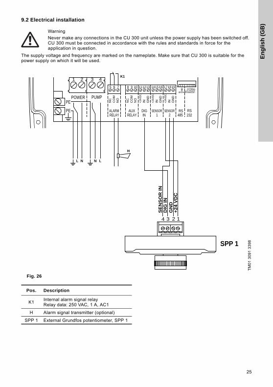
9.2 Electrical installation
The supply voltage and frequency are marked on the nameplate. Make sure that CU 300 is suitable for the power supply on which it will be used.
Fig. 26
Warning
Never make any connections in the CU 300 unit unless the power supply has been switched off. CU 300 must be connected in accordance with the rules and standards in force for the application in question.
TM
01
30
91
33
98
K1
POWERPE
PUMP
RELAYALARM
CO
MN
C
NO
NO
NC
CO
M
AUXRELAY IN
DIG
IN+24V
DC
GN
D
GN
D
+24V
DC
IN
SENSOR1 2
SENSOR
IN+24V
DC
GN
D
RS485
RS232
B GN
DA R
ID
TRR
XD
GN
D
5 6 7
1 2
1098
3 4
111213 161514 171819
PE
TXD
LNL N
H
4 3 2 1
SPP 1
SE
NS
OR
IN
GN
D
DIG
IN
+24
VD
C
Pos. Description
K1Internal alarm signal relayRelay data: 250 VAC, 1 A, AC1
H Alarm signal transmitter (optional)
SPP 1 External Grundfos potentiometer, SPP 1

En
glish
(GB
)
26
9.2.1 Mains supply
POWER, terminals 1, 2 and PE
Connect terminals 1 and 2 to the phase and neutral leads of the mains supply. You can connect each terminal to any of the two leads.
Connect the PE terminal to the green/yellow earth lead. You must connect each PE terminal to an earth lead of its own.
Maximum cross-section of the leads to be connected is 6 mm2.
Backup fuse: Maximum 16 A.
9.2.2 Pump supply
PUMP, terminals 3, 4 and PE
Connect terminals 3 and 4 to the phase and neutral leads of the pump. You can connect each terminal to any of the two leads.
Connect the PE terminal to the green/yellow earth lead. You must connect each PE terminal to an earth lead of its own.
Maximum cross-section of the leads to be connected is 6 mm2.
9.2.3 Alarm signal relay
ALARM RELAY, terminals 5, 6 and 7
Connect terminals 5, 6 and 7 to the internal alarm signal relay as follows:
• Terminal 5 NC (normally closed).
• Terminal 6 COM (common).
• Terminal 7 NO (normally open).
The relay operates when the alarm and warning limits are exceeded.
You can select manual or automatic restarting in the Grundfos GO display "Automatic restarting".
Manual restarting is carried out by means of the On/Off button on CU 300.
9.2.4 Potentiometer SPP 1
Connections between the SPP 1 and CU 300:
9.2.5 Required Grundfos GO settings
You must make the following Grundfos GO settings:
1. In display "Control mode" select "Open loop".
2. Set the external setpoint to "SPP 1", enabling speed control using the SPP 1. "Analog input 2" is set to "SPP 1".
3. Set "Digital input 1" to "Start"
10. CU 300 connected to water meter
10.1 Description
Using a water meter (pulse flow meter) enables:
• Monitoring of the flow.
• Stop of pump after a given quantity of water has been pumped.
• Indication of accumulated flow and the energy consumption required to pump 1 m3.
Figure 27 shows an example of an irrigation system incorporating a water meter.
Fig. 27
Note You must not connect the leads of the mains supply to terminals 3 and 4.
SPP 1 CU 300
1 17 (SENSOR 2 +24 VDC)
2 19 (SENSOR 2 GND)
3 12 (DIG IN)
4 18 (SENSOR 2 IN)
TM
01
26
59
46
01
Pos. Description
1 CU 300
2 Water meter (pulse flow meter)
1
2
En
glis
h (
GB
)
27
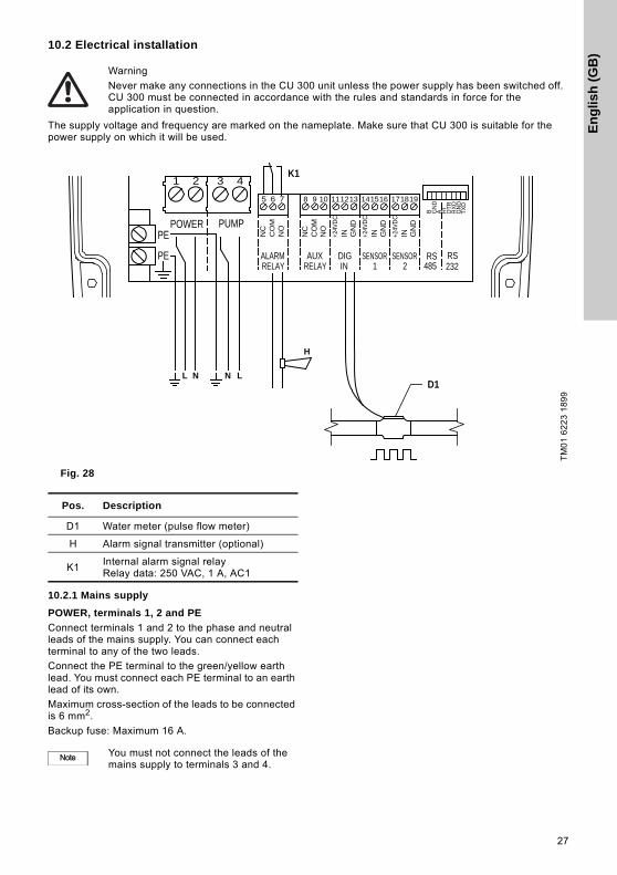
10.2 Electrical installation
The supply voltage and frequency are marked on the nameplate. Make sure that CU 300 is suitable for the power supply on which it will be used.
Fig. 28
10.2.1 Mains supply
POWER, terminals 1, 2 and PE
Connect terminals 1 and 2 to the phase and neutral leads of the mains supply. You can connect each terminal to any of the two leads.
Connect the PE terminal to the green/yellow earth lead. You must connect each PE terminal to an earth lead of its own.
Maximum cross-section of the leads to be connected is 6 mm2.
Backup fuse: Maximum 16 A.
Warning
Never make any connections in the CU 300 unit unless the power supply has been switched off. CU 300 must be connected in accordance with the rules and standards in force for the application in question.
TM
01
62
23
18
99
D1
K1
POWERPE
PUMP
RELAYALARM
CO
MN
C
NO
NO
NC
CO
M
AUXRELAY IN
DIG
IN+24V
DC
GN
D
GN
D
+24V
DC
IN
SENSOR1 2
SENSOR
IN+24V
DC
GN
D
RS485
RS232
B GN
DA R
ID
TRR
XD
GN
D
5 6 7
1 2
1098
3 4
111213 161514 171819
PE
TXD
LNL N
H
Pos. Description
D1 Water meter (pulse flow meter)
H Alarm signal transmitter (optional)
K1Internal alarm signal relayRelay data: 250 VAC, 1 A, AC1
Note You must not connect the leads of the mains supply to terminals 3 and 4.

En
glish
(GB
)
28
10.2.2 Pump supply
PUMP, terminals 3, 4 and PE
Connect terminals 3 and 4 to the phase and neutral leads of the pump. You can connect each terminal to any of the two leads.
Connect the PE terminal to the green/yellow earth lead. You must connect each PE terminal to an earth lead of its own.
Maximum cross-section of the leads to be connected is 6 mm2.
10.2.3 Alarm signal relay
ALARM RELAY, terminals 5, 6 and 7
Connect terminals 5, 6 and 7 to the internal alarm signal relay as follows:
• Terminal 5 NC (normally closed).
• Terminal 6 COM (common).
• Terminal 7 NO (normally open).
The relay operates when the alarm and warning limits are exceeded.
You can select manual or automatic restarting in the Grundfos GO display "Automatic restarting".
Manual restarting is carried out by means of the On/Off button on CU 300.
10.2.4 Water meter (pulse flow meter)
DIG IN, terminals 12 and 13
Connect terminals 12 and 13 to the water meter:
• Terminal 12 IN (signal input).
• Terminal 13 GND (earth).
10.2.5 Required Grundfos GO settings
You must make the following Grundfos GO settings:
1. Set "Digital input 1".
– Function: "Pulse-flow meas."
2. Set "Flow per pulse":Example: "10 l/pulse".
When you have set a value in this display, the actual flow will appear in status display "Digital input".
You must only set a value in the display "Stop limit, accum. flow" if stop of pump after a given quantity of water has been pumped is required.
Example:
• Stop limit, accum. flow: "7.5 m3".
• Sensor, accum. flow stop: "Digital input".
When you have set a value in this display, the "Accumulated flow" and "Energy per m3" will appear in the status displays "Accumulated flow" and "Specific energy".
11. Constant water level
11.1 Description
The water level can be kept constant by connecting an analog level sensor.
Figure 29 shows an example of an installation designed for maintaining a constant water level in the borehole.
Fig. 29
11.2 Function
CU 300 controls the pump speed and consequently adjusts the pump performance to the borehole yield.
1. When the water level is much higher than the desired level (setpoint), the pump is running at maximum performance.
2. When the level is coming closer to the desired level, the pump performance will be reduced.
3. When the desired level is reached, the pump speed will be so low that the pump performance is zero. After further 60 seconds, the pump will stop.
TM
01
26
71
46
01
Pos. Description
1 CU 300
2 Level sensor
1
2
Warning
Desired level
Warning

En
glis
h (
GB
)
29
11.3 Electrical installation
The supply voltage and frequency are marked on the nameplate. Make sure that CU 300 is suitable for the power supply on which it will be used.
Fig. 30
Warning
Never make any connections in the CU 300 unit unless the power supply has been switched off. CU 300 must be connected in accordance with the rules and standards in force for the application in question.
TM
01
62
13
24
00
POWERPE
PUMP
RELAYALARM
CO
MN
C
NO
NO
NC
CO
M
AUXRELAY IN
DIG
IN+24V
DC
GN
D
GN
D
+24V
DCIN
SENSOR1 2
SENSOR
IN+24V
DC
GN
D
RS485
RS232
B GN
DA R
ID
TR
RX
DG
ND5 6 7
1 2
1098
3 4
111213 161514 171819
PE
TX
D
+24V
DC
4-20
mA
/ IN1
1
Pos. Description
1Connection of level sensor:• Terminal 14, 24 VDC supply• Terminal 15, signal input

En
glish
(GB
)
30
11.3.1 Mains supply
POWER, terminals 1, 2 and PE
Connect terminals 1 and 2 to the phase and neutral leads of the mains supply. You can connect each terminal to any of the two leads.
Connect the PE terminal to the green/yellow earth lead. You must connect each PE terminal to an earth lead of its own.
Maximum cross-section of the leads to be connected is 6 mm2.
Backup fuse: Maximum 16 A.
11.3.2 Pump supply
PUMP, terminals 3, 4 and PE
Connect terminals 3 and 4 to the phase and neutral leads of the pump. You can connect each terminal to any of the two leads.
Connect the PE terminal to the green/yellow earth lead. You must connect each PE terminal to an earth lead of its own.
Maximum cross-section of the leads to be connected is 6 mm2.
11.3.3 Alarm signal relay
ALARM RELAY, terminals 5, 6 and 7
Connect terminals 5, 6 and 7 to the internal alarm signal relay as follows:
• Terminal 5 NC (normally closed).
• Terminal 6 COM (common).
• Terminal 7 NO (normally open).
The relay operates when the alarm and warning limits are exceeded. See section 15.2.5 Limits, sensor 1 and 2.
11.3.4 Digital input
Connect terminals 12 and 13 with a short piece of wire to create a short circuit between them.
11.3.5 Level sensor
Connect terminals 14 and 15 to the level sensor:
• Terminal 14, 24 VDC (voltage supply).
• Terminal 15, IN (signal input).
11.3.6 Required Grundfos GO settings
You must make the following Grundfos GO settings:
1. In display "Control mode" select "Closed loop".
2. Set "Analog input 1".Example:
– sensor output signal (4-20 mA),
– setting range unit (m)
– setting range - head Min.: 0.0Max.: 60.Set the stop type.
– Sensor 1: "Empty".
3. Set the "Setpoint" e.g. desired water level (m).Example: 55 m.
– Rule: The maximum setting of the setpoint corresponds to the maximum value set in display "Analog input 1" less 5 m.In this case, 60 less 5 = 55 m.The water level can be kept within a tolerance of ± 1 % of the setting range.
4. Set "Digital input 1".
– "Start".
Note You must not connect the leads of the mains supply to terminals 3 and 4.

En
glis
h (
GB
)
31
12. CU 300 connected to RS-485
12.1 Description
Using the RS-485 input enables:
• communication via Grundfos fieldbus GENIbus
• connection to the Grundfos Remote Management (CIU 270) gateway for communication over long distances.
12.2 CU 300 connected to a PC directly
Figure 31 shows an example of an installation which is connected to a PC directly via the PC Tool link and GENIbus.
The installation shown in the example enables configuration, fault finding and servicing of the installation by means of a PC with a PC Tool CU 300 software. See fig. 31.
Fig. 31
CU 300 connected to GENIbus network:
Figure 32 shows an example of an installation connected to a GENIbus network with two CU 300 installations via the RS-485 input. The GENIbus network is connected to Grundfos Remote Management (CIU 270) through a PC with internet access.
The installation shown in the example enables configuration, fault finding, servicing, data logging of the connected installations over long distances. See fig. 32.
You can connect and communicate with up to 32 GENIbus units on one network.
The units can be:
• CU 300 units only
• CU 300 units in combination with other Grundfos products with GENIbus connection.
Contact Grundfos for further details.
Fig. 32
TM
06
36
19
07
15
Pos. Description
1 CU 300
2E.g. a pH sensor for monitoring of water quality
3 Level sensor
4 PC
5 PC Tool Link
5
TM
06
36
18
07
15
Pos. Description
1 CU 300
2 CIU 270
3 PC
11
3
2
WWW
CIU 27X

En
glish
(GB
)
32
12.3 Electrical installation
The supply voltage and frequency are marked on the nameplate. Make sure that CU 300 is suitable for the power supply on which it will be used.
Fig. 33
Warning
Never make any connections in the CU 300 unit unless the power supply has been switched off. CU 300 must be connected in accordance with the rules and standards in force for the application in question.
TM
06
36
00
06
15
POWERPE
PUMP
RELAYALARM
CO
MN
C
NO
NO
NC
CO
M
AUXRELAY IN
DIG
IN+24V
DC
GN
D
GN
D
+24V
DCIN
SENSOR1 2
SENSOR
IN+24V
DC
GN
D
RS485
RS232
B GN
DA R
ID
TRR
XD
GN
D
5 6 7
1 2
1098
3 4
111213 161514 171819
PE
TXD
RS
-485
B
RS
-485
-A
IN GN
D
RS485
RS232
B GN
DA R
ID
TRR
XD
GN
D
18 19
TXD
Y
RS-485
Pos. Description
RS-485 Connection of RS-485, GENIbus

En
glis
h (
GB
)
33
12.3.1 Mains supply
POWER, terminals 1, 2 and PE
Connect terminals 1 and 2 to the phase and neutral leads of the mains supply. You can connect each terminal to any of the two leads.
Connect the PE terminal to the green/yellow earth lead. You must connect each PE terminal to an earth lead of its own.
Maximum cross-section of the leads to be connected is 6 mm2.
Backup fuse: Maximum 16 A.
12.3.2 Pump supply
PUMP, terminals 3, 4 and PE
Connect terminals 3 and 4 to the phase and neutral leads of the pump. You can connect each terminal to any of the two leads.
Connect the PE terminal to the green/yellow earth lead. You must connect each PE terminal to an earth lead of its own.
Maximum cross-section of the leads to be connected is 6 mm2.
12.3.3 Alarm signal relay
ALARM RELAY, terminals 5, 6 and 7
Connect terminals 5, 6 and 7 to the internal alarm signal relay as follows:
• Terminal 5 NC (normally closed).
• Terminal 6 COM (common).
• Terminal 7 NO (normally open).
The relay operates when the alarm and warning limits are exceeded.
You can select manual or automatic restarting in the Grundfos GO display "Automatic restarting".
Manual restarting is carried out by means of the On/Off button on CU 300.
12.3.4 RS-485 input
The RS-485 input, terminals A, Y (GND) and B, is for external bus communication.
The communication is effected according to the Grundfos bus protocol, GENIbus, and is two-way communication.
CU 300 can communicate with a PC with the PC Tool CU 300 installed.
You need a PC Tool link adapter to communicate with a PC. Connect the adaptor to CU 300, terminals A, Y (GND) and B, for direct communication with a PC on a GENIbus network.
The PC Tool CU 300 enables configuration, monitoring and fault finding of the actual installation.
The RS-485 input is a low-voltage circuit. Therefore, you must separate all connections to terminals A, Y (GND) and B from network circuits by means of double or reinforced insulation.
A screened, twisted-pair cable is required. The maximum cable length is 1200 m.
Note You must not connect the leads of the mains supply to terminals 3 and 4.

En
glish
(GB
)
34
13. Alarm functions
13.1 No contact
The connection and/or communication between CU 300 and the motor is not established.
"No contact" is permanently on. See fig. 34.
Fig. 34
Important:
The alarm indication "No contact" will also appear if the pump and CU 300 do not have the same number (allocated by the Grundfos GO). The problem may occur e.g. in connection with replacing a motor or a CU 300.
Solution:
The pump and CU 300 must be allocated the same number via the Grundfos GO display "Number".
The alarm "No contact" makes the On/Off button on CU 300 inactive, and actual operating parameters cannot be called up. However, installation parameters can be called up.
"No contact" does not cause a pump stop.
13.2 Overvoltage
The supply voltage to the motor exceeds the maximum value allowed.
For more information about factory settings, see section 16. Technical data.
The motor is stopped and "Overvoltage" is permanently on. See fig. 35.
Fig. 35
Restarting
When the supply voltage lies within the voltage range of the motor, the motor will restart automatically.
TM
01
27
82
04
15
Possible cause Remedy
Motor is not an MSE 3 motor.
Install an MSE 3 motor.
Motor is not connected. Check connections.
Cable breakage. Check cable.
Poor or no connection. Check connections.
The cable length exceeds 200 m.
Reduce cable length.
CU 300 is defective. Replace CU 300.
The motor is defective. Replace motor.
No contact
Overvoltage
Undervoltage
Dry running
Speed reduction
Overtemperature
Overload
Sensor alarm
TM
01
27
83
04
15
Possible cause Remedy
Unstable power supply.Contact the power supply authorities.
Too high supply voltage.Contact the power supply authorities.Check installation.
Supply voltage outside voltage range of motor.
Check installation.
No contact
Overvoltage
Undervoltage
Dry running
Speed reduction
Overtemperature
Overload
Sensor alarm

En
glis
h (
GB
)
35
13.3 Undervoltage
The supply voltage to the motor is lower than the minimum value allowed.
For more information about the factory setting, see section 16. Technical data.
The motor is stopped and "Undervoltage" is permanently on. See fig. 36.
Fig. 36
Restarting
When the supply voltage lies within the voltage range of the motor, the motor will restart automatically.
13.4 Dry running
The purpose of the dry-running protection is to protect the pump in case of insufficient water flow.
The dry-running protection makes the conventional dry-running protection unnecessary.
No additional cables to the motor are required.
The dry-running alarm is activated when the load has been below the dry-running power limit for an accumulated time of 5 seconds.
The motor is stopped and "Dry running" is permanently on. See fig. 37.
Fig. 37
Restarting
After 5 minutes (factory setting), or the period set by means of the Grundfos GO display "Automatic restarting", the motor will restart automatically.
TM
01
27
84
04
15
Possible cause Remedy
Unstable power supply.Contact the power supply authorities.
Supply voltage outside voltage range of motor.
Check installation.
Voltage drop in mains is too big.
Increase wire cross-section.
No contact
Overvoltage
Undervoltage
Dry running
Speed reduction
Overtemperature
Overload
Sensor alarm
TM
01
27
85
04
15
Possible cause Remedy
The pump performance is too high compared to the borehole yield.
Replace pump with a smaller one.
Reduce pump performance using the Grundfos GO display "Maximum speed".
Borehole filter is blocked.
Borehole service is required.
No contact
Overvoltage
Undervoltage
Dry running
Speed reduction
Overtemperature
Overload
Sensor alarm

En
glish
(GB
)
36
13.5 Speed reduction
At a moderate undervoltage or overload of the motor, the speed is reduced, but the motor is not stopped. The speed reduction indicator light is on, and at the same time the undervoltage or overload light is on.
"Speed reduction" and "Undervoltage" or "Overload" are permanently on.
In fig. 38, the "Speed reduction" alarm was caused by undervoltage.
Fig. 38
Speed resuming
When the supply voltage lies within the voltage range of the motor again and the cause of the overload has disappeared, the motor resumes normal speed.
13.6 Overtemperature
The motor temperature is monitored continuously during operation.
The motor is factory-set to a maximum value. See section 16. Technical data.
The motor temperature has exceeded the maximum temperature limit. If the temperature is too high, there is a risk that the motor electronics will be damaged.
The motor is stopped and "Overtemperature" is permanently on. See fig. 39.
Fig. 39
A too high operating temperature may indicate that the installation needs service.
Restarting
When the motor electronics has cooled sufficiently, the motor will restart automatically. See section 16. Technical data.
TM
01
27
86
04
15
Possible cause Remedy
Pump is worn, causing overload.
Pump must be serviced.
Wrong combination of pump and motor, causing overload.
Replace pump or motor.
Unstable power supply, causing undervoltage.
Contact the power supply authorities.
Too big voltage drop over the cable, causing undervoltage.
Size cable to avoid too big voltage drop.
No contact
Overvoltage
Undervoltage
Dry running
Speed reduction
Overtemperature
Overload
Sensor alarm
TM
01
27
87
04
15
Possible cause Remedy
Insufficient cooling or flow velocity along motor.
Take out pump and install flow sleeve.
Insufficient cooling due to incrustation of the motor.
Clean motor. Install flow sleeve.
No contact
Overvoltage
Undervoltage
Dry running
Speed reduction
Overtemperature
Overload
Sensor alarm

En
glis
h (
GB
)
37
13.7 Overload
The motor is overloaded, i.e. the current consumption of the motor exceeds the limit value.
For more information about the factory setting, see section 16. Technical data.
The motor is stopped and "Overload" is permanently on. See fig. 40.
Fig. 40
Restarting:
After 5 minutes (factory setting), or the period set by means of the Grundfos GO display "Automatic restarting", the motor will restart automatically.
13.8 Sensor alarm
The sensor alarm is activated in two incidents:
• If a connected sensor has detected that an alarm limit has been exceeded.
• If the sensor signal has fallen outside the measuring range set.
The motor is stopped and the "Sensor alarm" is permanently on. See fig. 41.
Fig. 41
Restarting
After 5 minutes (factory setting), or the period set by means of the Grundfos GO display "Automatic restarting", the motor will restart automatically.
14. CU 300 with Grundfos GO The remote control Grundfos GO is used for wireless infra-red communication with CU 300. During communication, there must be visual contact between CU 300 and the Grundfos GO. See fig. 42.
Fig. 42 CU 300 communicating with Grundfos GO
The Grundfos GO offers possibilities of setting and status displays for CU 300.
When the communication between the Grundfos GO and CU 300 has been established, the red indicator light (A) in the On/Off button will flash.
For general use of the Grundfos GO, see the operating instructions for this unit.
The menu structure for the Grundfos GO and CU 300 is divided into three main menus, each containing a number of displays.
• Status
• Settings
• Alarms and warnings
See 14.1 Menu overview on page 38.
TM
01
27
88
04
15
Possible cause Remedy
Pump is defective. Pump must be serviced.
Sand or gravel in pump. Pump must be serviced.
Wrong combination of pump and motor.
Replace pump or motor.
TM
01
27
89
04
15
No contact
Overvoltage
Undervoltage
Dry running
Speed reduction
Overtemperature
Overload
Sensor alarm
No contact
Overvoltage
Undervoltage
Dry running
Speed reduction
Overtemperature
Overload
Sensor alarm
TM
06
35
02
04
15
A

En
glish
(GB
)
38
14.1 Menu overview
Status Section Page
External setpoint 15.1.1 External setpoint 40
Controlled from 15.1.2 Controlled from 40
Value, sensor 115.1.3 Value, sensor 1 and 2 40
Value, sensor 2
Motor temperature 15.1.4 Motor temperature 40
Motor speed 15.1.5 Motor speed 40
Digital input 15.1.6 Digital input 40
Specific energy 15.1.7 Specific energy 40
Accumulated flow 15.1.8 Accumulated flow 40
Power consumption 15.1.9 Power consumption 40
Energy consumption 15.1.10 Energy consumption 40
Operating hours 15.1.11 Operating hours 40
Number of starts 15.1.12 Number of starts 40
Settings Section Page
Operating mode 15.2.1 Operating mode 40
Control mode 15.2.2 Control mode 40
Setpoint 15.2.3 Setpoint 41
Analog input 115.2.4 Analog inputs 41
Analog input 2
Limits, sensor 1 15.2.5 Limits, sensor 1 and 2 41
Min. stop value, sensor 1 15.2.6 Min. stop value, sensor 1 and 2 41
Max. stop value, sensor 1 15.2.7 Max. stop value, sensor 1 and 2 41
Limits, sensor 2 15.2.5 Limits, sensor 1 and 2 41
Min. stop value, sensor 2 15.2.6 Min. stop value, sensor 1 and 2 41
Max. stop value, sensor 2 15.2.7 Max. stop value, sensor 1 and 2 41
External setpoint 15.2.8 External setpoint 41
Warning temperature 15.2.9 Warning, temperature 42
Digital input 1 15.2.10 Digital input 42
Flow per pulse 15.2.11 Flow per pulse 42
Stop limit, accum. flow 15.2.12 Stop limit, accumulated flow 42
Sensor, accum. flow stop 15.2.13 Sensor, accumulated flow stop 42
Stop type, sensor 115.2.14 Stop type, sensor 1 and 2 42
Stop type, sensor 2
Automatic restarting 15.2.15 Automatic restarting 42
Double restarting time 15.2.16 Double restarting time 42
Start delay 15.2.17 Start delay 43
Dewatering 15.2.18 Dewatering 43
Dewatering max. on time 15.2.19 Dewatering, maximum "On" and "Off" time
43Dewatering max. off time
Continues on page 39.

En
glis
h (
GB
)
39
Continued from page 38.
Settings Section Page
Dry-running protection 15.2.20 Dry-running protection 43
Dry-running stop 15.2.21 Dry-running stop 43
Maximum speed 15.2.22 Maximum speed 43
Buttons on product 15.2.23 Buttons on product 44
Number 15.2.24 Number 44
Store settings 15.2.25 Store settings 44
Recall settings 15.2.26 Recall settings 44
Undo 15.2.27 Undo 44
Unit configuration 15.2.28 Unit configuration 44
Alarms and warnings Section Page
Alarm log15.3.1 Alarm and warning logs 45
Warning log

En
glish
(GB
)
40
15. Description of functions
15.1 Status
The "Status" menu for CU 300 offers the possibility of reading operating parameters.
15.1.1 External setpoint
You can read the value of the external setpoint in this display.
15.1.2 Controlled from
This display shows the control source:
• CU 300
• external.
15.1.3 Value, sensor 1 and 2
You can read the values measured by sensor 1 and 2 in these displays.
15.1.4 Motor temperature
The actual temperature of the motor electronics stated in "° C" or "° F".
Tolerance: ± 5 %.
Relation to other displays:
To select "° F", choose this in display 15.2.28 Unit configuration.
15.1.5 Motor speed
The actual speed stated in min-1 (rpm).
Tolerance: ± 1 %.
15.1.6 Digital input
You can read the value measured by the digital input in this display. For instance, the actual flow is shown if the digital input has been connected to a pulse flowmeter and is setup to monitor the flow.
15.1.7 Specific energy
You can read the specific energy in this display.
15.1.8 Accumulated flow
You can read the pumped water quantity in this display.
15.1.9 Power consumption
You can read the actual power consumption in this display.
15.1.10 Energy consumption
You can read the total energy consumption in this display.
15.1.11 Operating hours
The value of operating hours is accumulated from the pump's birth and it cannot be reset.
The value is stored in the motor electronics, and it is kept even if CU 300 is replaced.
The value is updated in the software every 2 minutes of continuous operation. The displayed value is updated every two hours.
15.1.12 Number of starts
The value of number of starts is accumulated from the pump's birth and it cannot be reset.
The value is stored in the motor electronics, and it is kept even if CU 300 is replaced.
15.2 Settings
The "Settings" menu for CU 300 offers the possibility of setting operating parameters.
15.2.1 Operating modeSelect one of the following operating modes:
• Max.Pump operation is set to maximum speed, irrespective of setpoint. The maximum speed is set in display 15.2.22 Maximum speed (default: 10,700 min-1).
• Normal.Normal operating mode, i.e. pump operation is based on the setpoint set in display 15.2.3 Setpoint.Examples: Speed set in display 15.2.3 Setpoint or sensor control.
• Min.Pump operation is set to minimum speed, 3000 min-1, irrespective of setpoint.
• Stop.The pump is stopped.
Factory setting
"Stop".
15.2.2 Control mode
The following settings are available:
• Open loop.The speed is set to normal operation based on the setpoint set in display 15.2.3 Setpoint (e.g. 10,700 min-1) or controlled by means of a signal connected to analog input 2.See section 9. CU 300 connected to potentiometer.
• Closed loop.Controlling according to sensor 1 (type and unit).Example: Constant-pressure control.See section 6. CU 300 with constant-pressure control - 0 to 10 bar.
Relation to other displays:
The unit (min-1) of display 15.2.3 Setpoint is changed according to the unit of the sensor installed.
Factory setting
"Open loop"

En
glis
h (
GB
)
41
15.2.3 SetpointSetting range: 3000-10,700 min-1 (100 min-1 intervals).
Dry-running protection
If you use "Setpoint" to reduce the speed, the dry-running protection will apply only in the "maximum speed" range, i.e. maximum speed less than 1000 min-1. See section 4.3.1 Function.
Relation to other displays
The setting in display 15.2.3 Setpoint is overridden by the "Max." and "Min." settings in display 15.2.1 Operating mode.
If you select "Closed loop" in display 15.2.2 Control mode, the setpoint is set within the setting range of the installed sensor.Example: If the analog input 1 is connected to a pressure sensor using the unit metre (m) and the measuring range (0-60), you can set the setpoint between 0 and 55 m in display 15.2.3 Setpoint.
Factory setting
"10,700 min-1"
15.2.4 Analog inputs
Make the following settings according to sensor type:
• Sensor output signal: "-" (not active), 0-20 mA, 4-20 mA, 0-10 V, 2-10 V.
• Setting range unit: m3/h, m, %, GPM, ft.
Setting range:
• Minimum value: 0-249 (0, 1, 2, ....249).
• Maximum value: 1-250 (1, 2, ....250).
Factory setting
Sensor output signal: "Not active"
Setting range unit: "m".
15.2.5 Limits, sensor 1 and 2
In these displays, you can set the warning and alarm limits for sensor 1 and 2.
15.2.6 Min. stop value, sensor 1 and 2
In these displays, you can set the minimum value at which the pump must stop for sensor 1 and 2.
15.2.7 Max. stop value, sensor 1 and 2
In these displays, you can set the maximum value at which the pump must stop for sensor 1 and 2.
15.2.8 External setpoint
Set the pump performance control by means of an external signal.
To be used in the following two situations:
• For installations including a potentiometer.
• In large SCADA systems.In SCADA systems, this function makes it possible to control pump performance via remote controlling (e.g. via a PC).
The following settings are available:
• SPP 1.Grundfos potentiometer.See section 2.1 Expansion possibilities.
• 4-20 mA.
• 0-20 mA.
• 2-10 V.
• 0-10 V.
• "Not active"No external setpoint setting made.
Description
By connecting a current or voltage signal to analog input 2, you can control the motor speed between the setpoint set in display 15.2.3 Setpoint and the lowest speed of 3000 min-1.
If the setpoint is set to 10,700 min-1 in display15.2.3 Setpoint, the motor speed can be changed between 3000 and 10,700 min-1.
The actual setpoint is calculated by CU 300 and shown in display 15.2.3 Setpoint.
If an SPP 1 potentiometer is connected, the internal voltage supply of CU 300 is used to generate the signal.
See section 9. CU 300 connected to potentiometer.
Relation to other displays
If you have set display 15.2.2 Control mode to "Closed loop" instead of "Open loop" (factory setting), the controlling is based on signals from analog input 1. Therefore, the unit in display 15.2.3 Setpoint is changed from min-1 to the unit of sensor 1 (m3/h, m, %, GPM, ft).
Factory setting
"Not active".

En
glish
(GB
)
42
15.2.9 Warning, temperature
Set the temperature warning limit of the motor.
Setting range: "-" (not active), 2, 4, 6, ....85 °C.
Set the temperature warning limit between normal operating temperature and maximum temperature.
Relation to other displays
You find the actual operating temperature in display 15.1.4 Motor temperature.
If the temperature warning limit is exceeded, the alarm signal relay operates.
Advantage
Instead of a sudden stop without a warning, you get the following:
• Information that the motor temperature is rising.
• The possibility of planning service of the installation.
Usage
You can use this function e.g. if the pumped liquid contains a relatively high level of ochre.
Factory setting
"Not active".
15.2.10 Digital input
Select one of the following functions:
• The digital sensor connected to the digital input (flow measuring).
• The external on/off switch for the pump.
The following functions are available:
• Not active.
• Stop. The pump is stopped when a switch connected to terminals 12 and 13 is closed. No l/pulse to be set.See section 15.2.10 Digital input.
• Start. The pump is started when a switch connected to terminals 12 and 13 is closed. No l/pulse to be set.See section 15.2.10 Digital input.
• Flow. If you have selected "Flow", the l/pulse value must also be set.Setting range: "-" (not active), 0.1, 0.2, 0.3,....20, 21, 22, ....100 l/pulse.
Relation to other displays:
The selection of "Flow" in this display makes display 15.2.10 Digital input available, i.e. status of digital input.
Factory setting
"Not active".
15.2.11 Flow per pulse
In this display the pumped volume per pulse is set.
Setting range: 0.0, 0.1, 0.2, 0.3, ....20, 21, 22, ....100 l/pulse.
For more information, see section 15.2.10 Digital input.
Factory setting
"0.0 l/pulse"
15.2.12 Stop limit, accumulated flow
In this display, you can set a limit at a specific amount of pumped water where the pump must stop.
Factory setting
"Disabled".
15.2.13 Sensor, accumulated flow stop
In this display, you can select the sensor for monitoring the accumulated flow.
Factory setting
"Disabled".
15.2.14 Stop type, sensor 1 and 2
In these displays, you can set the stop type for sensor 1 and 2. For further information, see 8.2.3 Start and stop limits.
Factory setting
"Disabled".
15.2.15 Automatic restarting
Set the automatic restart time from stop to restart attempt.
The following settings are available:
• "Enabled"
• "Disabled"
• 0 to 254 minutes.
Factory setting
"5 minutes".
15.2.16 Double restarting time
The following settings are available:
• enabled
• disabled.
When you have selected "Enabled", the restart time set will be doubled automatically for every 10 motor stops caused by an alarm. The time is doubled up to a stop time of 4 hours. After 10 hours of operation without an alarm, the restart time is automatically set to:
• The time set in the "Time" field.
• 5 minutes (factory setting) if no setting was made in the "Time" field.
Relation to other displays:
If you have selected "Double", the dewatering function is disabled.
Note The maximum temperature depends on the motor type.

En
glis
h (
GB
)
43
15.2.17 Start delay
Set a start delay.
This function is used in installations where several pumps are connected to the same pipeline and where it is required that the pumps do not start up at the same time.
The SQE pumps have a built-in soft starter, which takes the starting current into account.
Setting range: 0-60 s.
Factory setting
"0 s"
15.2.18 Dewatering
For more information about the dewatering function, see 4.5 Description of the dewatering function.
The following settings are available:
• enabled
• disabled.
Relation to other displays
You can set the pump on and off times in the displays 15.2.19 Dewatering, maximum "On" and "Off" time.
Factory setting
"Disabled".
15.2.19 Dewatering, maximum "On" and "Off" time
In these displays, you set the maximum "On" and "Off" time for the pump for the dewatering function.
For more information, see section 4.5 Description of the dewatering function.
Operating indication
The dry-running alarm indication on CU 300 is automatically disabled, when this display setting is made.
When you select the setting "Disabled", the dewatering function is disabled, and the dry-running alarm indication can be activated again.
Relation to other displays:
If you select "Double" in display 15.2.15 Automatic restarting, the dewatering function is disabled.
Factory setting
"Disabled"
15.2.20 Dry-running protection
The following settings are available:
• enabled
• disabled.
The setting in this display applies to both the dewatering function and the dry-running protection.
In certain installations, it may be necessary to disable the dry-running protection.
For further information, see section 4.3 Description of dry-running protection.
Factory setting
"Enabled".
15.2.21 Dry-running stop
The dry-running stop value (dry-running power limit) is factory-set.
The value depends on the actual motor.
The factory setting depends on the power rating of the motor. See section 16. Technical data.
When the dry-running protection or the dewatering function is to be enabled, the minimum value of the pump power input must be set in this display.
For further information, see section 4.5 Description of the dewatering function.
Setting range: 0-2500 W.
Relation to other displays
15.2.20 Dry-running protection must be set to "Enabled".
If you have enabled "Double" in display 15.2.16 Double restarting time, the dewatering function is disabled.
You can read the actual pump power input in display 15.1.9 Power consumption.
Factory setting
15.2.22 Maximum speed
Set the maximum speed.
Setting range: 3000 - 10,700 min-1.
Factory setting
10,700 min-1.
Motor size Dry-running stop
0.7 kW 300 W
0.7 kW (SQ/SQE 2-55) 550 W
1.15 kW 680 W
1.55 kW 800 W
1.85 kW 900 W

En
glish
(GB
)
44
15.2.23 Buttons on product
In this display, you can disable the On/Off button on the control unit for protective reasons.
You can set the On/Off button to:
• "Active"
• "Not active".
Factory setting
"Active".
15.2.24 Number
Allocate a number to CU 300 and the pump connected. CU 300 and the pump must have the same number.
Setting range: "Not active", 1, 2, ....199.
Once a number setting has been made, the factory setting (not active) is no longer available.
In connection with bus communication, you must allocate a number to CU 300 and the pump.
If CU 300 and the pump do not have the same number, the alarm "No contact" will be indicated.
Factory setting
"Not active".
15.2.25 Store settings
You can store the actual settings for later use in this display.
15.2.26 Recall settings
You can recall the last stored settings that the pump will then use in this display.
15.2.27 Undo
You can undo previously made settings in this display.
15.2.28 Unit configuration
You can select between SI and US units in this display. The setting can be made generally for all parameters or customised for each individual parameter.
NoteWhen allocating a number, the power supply to other CU 300 units, if any, must be switched off.

En
glis
h (
GB
)
45
15.3 Alarms and warnings
15.3.1 Alarm and warning logs
These displays show the types of warnings and alarms that may have appeared.
Possible warnings and alarms are described in the following table:
Relation to other displays:
The setting in display 15.2.3 Setpoint is overridden by the "Max." and "Min." settings in display 15.2.1 Operating mode.
If you select "Closed loop" in display 15.2.2 Control mode, the setpoint is set within the setting range of the installed sensor.Example: If the analog input 1 is connected to a pressure sensor using the unit metre (m) and the measuring range (0-60), you can set the setpoint between 0 and 55 m in display 15.2.3 Setpoint.
Indication Description
No fault indication No alarms are registered by CU 300.
No contact to pump No communication between CU 300 and the pump.
Overvoltage The supply voltage exceeds the limit value.
Undervoltage The supply voltage is below the limit value.
Dry running The dry-running protection of the pump has been activated.
Overtemperature The motor temperature exceeds the limit value.
Overload The current consumption of the motor exceeds the limit value.
Alarm, sensor 1The sensor 1 signal has fallen outside the measuring range set.Note: The sensor number refers to the terminal connection input number.
Alarm, sensor 2The sensor 2 signal has fallen outside the measuring range set.Note: The sensor number refers to the terminal connection input number.
Sensor 1 defectiveThe sensor signal of a 4-20 mA or 2-10 V sensor is below 2 mA or 1 V respectively.
Sensor 2 defectiveThe sensor signal of a 4-20 mA or 2-10 V sensor is below 2 mA or 1 V respectively.
Warning, sensor 1 The sensor 1 warning limit has been exceeded.
Warning, sensor 2 The sensor 2 warning limit has been exceeded.
Warning, temperature The temperature warning limit has been exceeded.

En
glish
(GB
)
46
16. Technical data
Supply voltage
1 x 100-240 V - 10 %/+ 6 %, 50/60 Hz, PE.
Power consumption
5 W.
Backup fuse
Maximum 16 A.
Current consumption
Maximum 130 mA.
Mains borne signalling
Frequency shift keying (FSK).
(132.45 kHz, ± 0.6 kHz).
Enclosure class
IP55.
Maximum difference between CU 300 and pump
200 metres.
Ambient temperature
• During operation: -30 to 50 °C (must not be exposed to direct sunlight).
• During storage: -30 to 60 °C.
Weight
2.0 kg.
Relative air humidity
Maximum 95 %.
Materials
The CU 300 box is made of black PPO.
EMC (Electromagnetic compatibility)
See Declaration of conformity on page 48.
Dimensional sketch
Fig. 43
Inputs/output
TM
01
27
81
46
01
232 114
195
Ala
rm r
ela
y Potential-free changeover contact.Maximum contact load: 250 VAC. Maximum current: 1 A.Minimum contact load: 5 VDC, 10 mA.Specifications: 250 VAC, 8 A, AC1.
Au
xilia
ry r
ela
y Potential-free changeover contact.Maximum contact load: Safety extra-low voltage to be used only. Maximum current: 1 A.Minimum contact load: 5 VDC, 10 mA.Specifications: 250 VAC, 8 A, AC1.
Dig
ital i
np
ut
External potential-free contact.Logic "0": Uin > 3.2 V.Logic "1": Uin < 0.9 V.
Se
nso
r 1
Voltage signal: 0-10 VDC/2-10 VDC, Ri = 11 kΩ. Tolerance: at maximum voltage signal.Screened cable is recommended.Maximum cable length: 500 m.Current signal: DC 0-20 mA/4-20 mA, Ri = 500 Ω. Tolerance: ± 3 % at maximum current signal.Screened cable is recommended.Maximum cable length: 500 m.
Se
nso
r 2
Potentiometer SPP 1: 0-24 VDC, 10 k (via internal voltage supply).Screened cable is recommended.Maximum cable length: 100 m.Voltage signal: 0-10 VDC/2-10 VDC, Ri = 11 kΩ.Tolerance: ± 3 % at maximum voltage signal.Screened cable is recommended.Maximum cable length: 500 m.Current signal: DC 0-20 mA/4-20 mA, Ri = 500 Ω.Tolerance: ± 3 % at maximum current signal.Screened cable is recommended.Maximum cable length: 500 m.
RS
-48
5 Grundfos fieldbus, GENIbus.0.25 - 1 mm2 screened 2-core cable.Maximum cable length: 1200 m.

En
glis
h (
GB
)
47
Factory settings
1) 200-240 V motors: Operation is guaranteed up to 280 VAC.100-115 V motors: Operation is guaranteed up to 150 VAC.In order to avoid unnecessary stops, the overvoltage stop limit is as stated.
2) Applies only to SQ/SQE 2-55.
Accuracy of Grundfos GO readings
Sensors
The sensor signal accuracy depends on the sensor type. See the sensor specifications in question.
17. DisposalThis product or parts of it must be disposed of in an environmentally sound way:
1. Use the public or private waste collection service.
2. If this is not possible, contact the nearest Grundfos company or service workshop.
Subject to alterations.
Alarm200-240 V motors
100-115 V motors
0.7 kW 1.15 kW 1.55 kW 1.85 kW 0.7 kW
Overvoltage1) 320 VAC 320 VAC 320 VAC 320 VAC 185 VAC
Undervoltage
Speed reduction: 190 V
Speed reduction: 190 V
Speed reduction: 210 V
Speed reduction: 210 V
Speed reduction: 90 V
Stop limit: 150 V Stop limit: 150 V Stop limit: 150 V Stop limit: 150 V Stop limit: 75 V
Dry-running stop
300 W550 W2) 680 W 800 W 900 W 300 W
Dry-running protection
"Active" (Grundfos GO setting). See section 15.2.20 Dry-running protection)
Speed reduction
In connection with undervoltage or overload
Electronics temperature
Stop limit: 65 °C Stop limit: 75 °C Stop limit: 85 °C Stop limit: 85 °C Stop limit: 85 °C
Restart: 55 °C Restart: 65 °C Restart: 75 °C Restart: 75 °C Restart: 75 °C
Overload 5.2 A 8.4 A 11 A 12.3 A 12.1 A
Sensor alarm "No sensor used" (Grundfos GO setting). See section 15.2.4 Analog inputs)
Display Accuracy
External setpoint ± 5 %
Motor temperature ± 5 %
Motor speed ± 1 %
Power input ± 5 %
Power consumption ± 5 %
Energy consumption ± 5 %

Declaration of conform
ity
48
Declaration of conformity 1
GB: EC/EU declaration of conformityWe, Grundfos, declare under our sole responsibility that the product CU 300, to which the declaration below relates, is in conformity with the Council Directives listed below on the approximation of the laws of the EC/EU member states.
Note: There are two sets of Council Directives and standards listed below. One set applies until and including 19th April 2016. The other set applies from 20th April 2016 and onwards.
These Directives and standards apply until and including 19th April 2016:– Low Voltage Directive (2006/95/EC).
Standards used:EN 60335-1:2012
– EMC Directive (2004/108/EC).Standards used:EN 55014-1:2006 + A1:2009 + A2:2011EN 55014-2:1997 + A1:2001 + A2:2008
These Directives and standards apply from 20th April 2016 and onwards:— Low Voltage Directive (2014/35/EU).
Standards used:EN 60335-1:2012
— EMC Directive (2014/30/EU).Standards used:EN 55014-1:2006 + A1:2009 + A2:2011EN 55014-2:1997 + A1:2001 + A2:2008
This EC/EU declaration of conformity is only valid when published as part of the Grundfos installation and operating instructions (publication number 96427972 0915).
Bjerringbro, 15th June 2015
Svend Aage KaaeDirector
Grundfos Holding A/SPoul Due Jensens Vej 7
8850 Bjerringbro, Denmark
Person authorised to compile the technical file and empowered to sign the EC declaration of conformity.

49

Gru
nd
fos co
mp
anies
ArgentinaBombas GRUNDFOS de Argentina S.A.Ruta Panamericana km. 37.500 Centro Industrial Garin1619 Garín Pcia. de B.A.Phone: +54-3327 414 444Telefax: +54-3327 45 3190
AustraliaGRUNDFOS Pumps Pty. Ltd. P.O. Box 2040 Regency Park South Australia 5942 Phone: +61-8-8461-4611 Telefax: +61-8-8340 0155
AustriaGRUNDFOS Pumpen Vertrieb Ges.m.b.H.Grundfosstraße 2 A-5082 Grödig/Salzburg Tel.: +43-6246-883-0 Telefax: +43-6246-883-30
BelgiumN.V. GRUNDFOS Bellux S.A. Boomsesteenweg 81-83 B-2630 Aartselaar Tél.: +32-3-870 7300 Télécopie: +32-3-870 7301
BelarusПредставительство ГРУНДФОС в Минске220125, Минскул. Шафарнянская, 11, оф. 56, БЦ «Порт»Тел.: +7 (375 17) 286 39 72/73Факс: +7 (375 17) 286 39 71E-mail: [email protected]
Bosna and HerzegovinaGRUNDFOS SarajevoZmaja od Bosne 7-7A,BH-71000 SarajevoPhone: +387 33 592 480Telefax: +387 33 590 465www.ba.grundfos.come-mail: [email protected]
BrazilBOMBAS GRUNDFOS DO BRASILAv. Humberto de Alencar Castelo Branco, 630CEP 09850 - 300São Bernardo do Campo - SPPhone: +55-11 4393 5533Telefax: +55-11 4343 5015
BulgariaGrundfos Bulgaria EOODSlatina DistrictIztochna Tangenta street no. 100BG - 1592 SofiaTel. +359 2 49 22 200Fax. +359 2 49 22 201email: [email protected]
CanadaGRUNDFOS Canada Inc. 2941 Brighton Road Oakville, Ontario L6H 6C9 Phone: +1-905 829 9533 Telefax: +1-905 829 9512
ChinaGRUNDFOS Pumps (Shanghai) Co. Ltd.10F The Hub, No. 33 Suhong RoadMinhang DistrictShanghai 201106PRCPhone: +86 21 612 252 22Telefax: +86 21 612 253 33
CroatiaGRUNDFOS CROATIA d.o.o.Buzinski prilaz 38, BuzinHR-10010 ZagrebPhone: +385 1 6595 400 Telefax: +385 1 6595 499www.hr.grundfos.com
Czech RepublicGRUNDFOS s.r.o.Čajkovského 21779 00 OlomoucPhone: +420-585-716 111Telefax: +420-585-716 299
DenmarkGRUNDFOS DK A/S Martin Bachs Vej 3 DK-8850 Bjerringbro Tlf.: +45-87 50 50 50 Telefax: +45-87 50 51 51 E-mail: [email protected]/DK
EstoniaGRUNDFOS Pumps Eesti OÜPeterburi tee 92G11415 TallinnTel: + 372 606 1690Fax: + 372 606 1691
FinlandOY GRUNDFOS Pumput AB Trukkikuja 1 FI-01360 Vantaa Phone: +358-(0) 207 889 500Telefax: +358-(0) 207 889 550
FrancePompes GRUNDFOS Distribution S.A. Parc d’Activités de Chesnes 57, rue de Malacombe F-38290 St. Quentin Fallavier (Lyon) Tél.: +33-4 74 82 15 15 Télécopie: +33-4 74 94 10 51
GermanyGRUNDFOS GMBHSchlüterstr. 3340699 ErkrathTel.: +49-(0) 211 929 69-0 Telefax: +49-(0) 211 929 69-3799e-mail: [email protected] in Deutschland:e-mail: [email protected]
GreeceGRUNDFOS Hellas A.E.B.E. 20th km. Athinon-Markopoulou Av. P.O. Box 71 GR-19002 Peania Phone: +0030-210-66 83 400 Telefax: +0030-210-66 46 273
Hong KongGRUNDFOS Pumps (Hong Kong) Ltd. Unit 1, Ground floor Siu Wai Industrial Centre 29-33 Wing Hong Street & 68 King Lam Street, Cheung Sha Wan Kowloon Phone: +852-27861706 / 27861741 Telefax: +852-27858664
HungaryGRUNDFOS Hungária Kft.Park u. 8H-2045 Törökbálint, Phone: +36-23 511 110Telefax: +36-23 511 111
IndiaGRUNDFOS Pumps India Private Limited118 Old Mahabalipuram RoadThoraipakkamChennai 600 096Phone: +91-44 2496 6800
IndonesiaPT. GRUNDFOS POMPAGraha Intirub Lt. 2 & 3Jln. Cililitan Besar No.454. Makasar, Jakarta TimurID-Jakarta 13650Phone: +62 21-469-51900Telefax: +62 21-460 6910 / 460 6901
IrelandGRUNDFOS (Ireland) Ltd. Unit A, Merrywell Business ParkBallymount Road LowerDublin 12 Phone: +353-1-4089 800 Telefax: +353-1-4089 830
ItalyGRUNDFOS Pompe Italia S.r.l. Via Gran Sasso 4I-20060 Truccazzano (Milano)Tel.: +39-02-95838112 Telefax: +39-02-95309290 / 95838461
JapanGRUNDFOS Pumps K.K.Gotanda Metalion Bldg., 5F, 5-21-15, Higashi-gotandaShiagawa-ku, Tokyo141-0022 JapanPhone: +81 35 448 1391Telefax: +81 35 448 9619
KoreaGRUNDFOS Pumps Korea Ltd.6th Floor, Aju Building 679-5Yeoksam-dong, Kangnam-ku, 135-916Seoul, KoreaPhone: +82-2-5317 600Telefax: +82-2-5633 725
LatviaSIA GRUNDFOS Pumps Latvia Deglava biznesa centrsAugusta Deglava ielā 60, LV-1035, Rīga,Tālr.: + 371 714 9640, 7 149 641Fakss: + 371 914 9646
LithuaniaGRUNDFOS Pumps UABSmolensko g. 6LT-03201 VilniusTel: + 370 52 395 430Fax: + 370 52 395 431

Gru
nd
fos
com
pan
ies
MalaysiaGRUNDFOS Pumps Sdn. Bhd.7 Jalan Peguam U1/25Glenmarie Industrial Park40150 Shah AlamSelangor Phone: +60-3-5569 2922Telefax: +60-3-5569 2866
MexicoBombas GRUNDFOS de México S.A. de C.V. Boulevard TLC No. 15Parque Industrial Stiva AeropuertoApodaca, N.L. 66600Phone: +52-81-8144 4000 Telefax: +52-81-8144 4010
NetherlandsGRUNDFOS NetherlandsVeluwezoom 351326 AE AlmerePostbus 220151302 CA ALMERE Tel.: +31-88-478 6336 Telefax: +31-88-478 6332E-mail: [email protected]
New ZealandGRUNDFOS Pumps NZ Ltd.17 Beatrice Tinsley CrescentNorth Harbour Industrial EstateAlbany, AucklandPhone: +64-9-415 3240Telefax: +64-9-415 3250
NorwayGRUNDFOS Pumper A/S Strømsveien 344 Postboks 235, Leirdal N-1011 Oslo Tlf.: +47-22 90 47 00 Telefax: +47-22 32 21 50
PolandGRUNDFOS Pompy Sp. z o.o.ul. Klonowa 23Baranowo k. PoznaniaPL-62-081 PrzeźmierowoTel: (+48-61) 650 13 00Fax: (+48-61) 650 13 50
PortugalBombas GRUNDFOS Portugal, S.A. Rua Calvet de Magalhães, 241Apartado 1079P-2770-153 Paço de ArcosTel.: +351-21-440 76 00Telefax: +351-21-440 76 90
RomaniaGRUNDFOS Pompe România SRLBd. Biruintei, nr 103 Pantelimon county IlfovPhone: +40 21 200 4100Telefax: +40 21 200 4101E-mail: [email protected]
RussiaООО Грундфос Россия109544, г. Москва, ул. Школьная, 39-41, стр. 1Тел. (+7) 495 564-88-00 (495) 737-30-00Факс (+7) 495 564 88 11E-mail [email protected]
Serbia Grundfos Srbija d.o.o.Omladinskih brigada 90b11070 Novi Beograd Phone: +381 11 2258 740Telefax: +381 11 2281 769www.rs.grundfos.com
SingaporeGRUNDFOS (Singapore) Pte. Ltd.25 Jalan Tukang Singapore 619264 Phone: +65-6681 9688 Telefax: +65-6681 9689
SlovakiaGRUNDFOS s.r.o.Prievozská 4D 821 09 BRATISLAVA Phona: +421 2 5020 1426sk.grundfos.com
SloveniaGRUNDFOS d.o.o.Šlandrova 8b, SI-1231 Ljubljana-ČrnučePhone: +386 31 718 808Telefax: +386 (0)1 5680 619E-mail: [email protected]
South AfricaGRUNDFOS (PTY) LTDCorner Mountjoy and George Allen RoadsWilbart Ext. 2Bedfordview 2008Phone: (+27) 11 579 4800Fax: (+27) 11 455 6066E-mail: [email protected]
SpainBombas GRUNDFOS España S.A. Camino de la Fuentecilla, s/n E-28110 Algete (Madrid) Tel.: +34-91-848 8800 Telefax: +34-91-628 0465
SwedenGRUNDFOS AB Box 333 (Lunnagårdsgatan 6) 431 24 Mölndal Tel.: +46 31 332 23 000Telefax: +46 31 331 94 60
SwitzerlandGRUNDFOS Pumpen AG Bruggacherstrasse 10 CH-8117 Fällanden/ZH Tel.: +41-44-806 8111 Telefax: +41-44-806 8115
TaiwanGRUNDFOS Pumps (Taiwan) Ltd. 7 Floor, 219 Min-Chuan Road Taichung, Taiwan, R.O.C. Phone: +886-4-2305 0868Telefax: +886-4-2305 0878
ThailandGRUNDFOS (Thailand) Ltd. 92 Chaloem Phrakiat Rama 9 Road,Dokmai, Pravej, Bangkok 10250Phone: +66-2-725 8999Telefax: +66-2-725 8998
TurkeyGRUNDFOS POMPA San. ve Tic. Ltd. Sti.Gebze Organize Sanayi Bölgesi Ihsan dede Caddesi,2. yol 200. Sokak No. 20441490 Gebze/ KocaeliPhone: +90 - 262-679 7979Telefax: +90 - 262-679 7905E-mail: [email protected]
UkraineБізнес Центр ЄвропаСтоличне шосе, 103м. Київ, 03131, Україна Телефон: (+38 044) 237 04 00 Факс.: (+38 044) 237 04 01E-mail: [email protected]
United Arab EmiratesGRUNDFOS Gulf DistributionP.O. Box 16768Jebel Ali Free ZoneDubaiPhone: +971 4 8815 166Telefax: +971 4 8815 136
United KingdomGRUNDFOS Pumps Ltd. Grovebury Road Leighton Buzzard/Beds. LU7 4TL Phone: +44-1525-850000 Telefax: +44-1525-850011
U.S.A.GRUNDFOS Pumps Corporation 17100 West 118th TerraceOlathe, Kansas 66061Phone: +1-913-227-3400 Telefax: +1-913-227-3500
UzbekistanGrundfos Tashkent, Uzbekistan The Rep-resentative Office of Grundfos Kazakhstan in Uzbekistan38a, Oybek street, TashkentТелефон: (+998) 71 150 3290 / 71 150 3291Факс: (+998) 71 150 3292
Addresses Revised 29.09.2015

www.grundfos.com
96427972 0915
ECM: 1156881 The
nam
e G
run
dfos
, the
Gru
ndf
os lo
go, a
nd b
e th
ink
inn
ova
te a
re r
egi
ster
ed t
rade
ma
rks
ow
ned
by
Gru
ndfo
s H
old
ing
A/S
or
Gru
ndf
os A
/S, D
enm
ark.
All
righ
ts r
ese
rved
wo
rldw
ide.
© C
opyr
ight
Gru
ndfo
s H
oldi
ng A
/S


![Grundfos SL1.50.65.22.2.50D.C pump - Lenntech › uploads › grundfos › 98624257 › ...Printed from Grundfos Product Centre [2018.06.003] Position Qty. Description 1 SL1.50.65.22.2.50D.C](https://static.fdocuments.in/doc/165x107/60ce95cbe9a1406f7c619e35/grundfos-sl1506522250dc-pump-lenntech-a-uploads-a-grundfos-a-98624257.jpg)
