Grumman F-14 Super Tomcat - jetworks.online · F-14 Tomcat Page 2 ‘Tomcat’ History Designers...
64
Construction Guide © 2019 Craig Clarkstone. All rights reseved 4th Generation Jet Fighter Parkjet F-14 Super Tomcat Grumman
Transcript of Grumman F-14 Super Tomcat - jetworks.online · F-14 Tomcat Page 2 ‘Tomcat’ History Designers...

Construction Guide© 2019 Craig Clarkstone. All rights reseved
4th Generation Jet Fighter
ParkjetF-14 Super Tomcat
Grumman

Page 2F-14 Tomcat
‘Tomcat’ History Designers NotesThe Grumman F-14 Tomcat is an American supersonic, twin-engine, two-seat, twin-tail, variable-sweep wing fighter aircraft. It was the first such U.S. jet fighter with twin tails.
The Tomcat was developed for the United States Navy's Naval Fighter Experimental (VFX) program after the collapse of the F-111B project. The F-14 was the first of the American Teen Series fighters, which were designed incorporating air combat experience against MiG fighters during the Vietnam War.
The F-14 first flew on 21 December 1970 and made its first deployment in 1974 with the U.S. Navy aboard USS Enterprise (CVN-65), replacing the McDonnell Douglas F-4 Phantom II. The F-14 served as the U.S. Navy's primary maritime air superiority fighter, fleet defense interceptor, and tactical aerial reconnaissance platform into the 2000s. The Low Altitude Navigation and Targeting Infrared for Night (LANTIRN) pod system were added in the 1990s and the Tomcat began performing precision ground-attack missions.
In the 1980s, F-14s were used as land-based interceptors by the Islamic Republic of Iran Air Force during the Iran–Iraq War, where they saw combat against Iraqi warplanes. Iranian F-14s reportedly shot down at least 160 Iraqi aircraft during the war, while only 12 to 16 Tomcats were lost; at least half of these losses were due to accidents.
The Tomcat was retired from the U.S. Navy's active fleet on 22 September 2006, having been supplanted by the Boeing F/A-18E/F Super Hornet.
The F-14 remains in service with Iran's air force, having been exported to Iran in 1976. F-14s operated by the IRIAF have recently seen use against ISIL in the Middle East, and have been recorded escorting and accompanying Russian Air Force Tu-95 and Tu-160 strategic bombers on missions over Syria.
Made famous by the much loved ‘80's film Top Gun, for many this is the very definition of what a Jet fighter is.
This F-14 tomcat design is undoubtedly one of the more complex parkjets to build but is a very rewarding design. There is nothing more iconic than seeing the Tomcat shape in the air, and the gleeful comments when the wings sweep mid air.
This design has three powerplant options, twin pusher, single pusher and twin EDF(50mm - 64mm).
My very first parkjet was Steve Shumate’s Tomcat in the Jolly Rogers Scheme, which I built some 6 years ago. With a various Tomcat Parkjet designs around, I wanted to emphasize more scale features, and to ensure that it will be a good flyer for EDF. This is why it is a little larger parkjet - to accommodate twin 64mm EDF.
Like many of the Jetworks designs, I’ve accommodated 3d printed parts to help to get the scale look and to make it easier to build with including F-14A exhausts and glove vanes and F-14D exhausts.
There are loads of liveries to choose from - I’m particularly fond of the VF-1 Wolfpack scheme which I remember fondly building as a plastic model kit as a young teenager.
visit us at : www.jetworks.online

Construction

Adhesives> For the majority of construction : - UHU Creativ for Styrofoam (also called UHU POR) - 3M 77 Spray adhesive.>For wing spars and motor mounts : - Epoxy. (5 and 15mins cure times are the most convenient) micro-baloons can be added to reduce weight.> For servo’s / and quick grab : - Hot melt glue gun - Caution if the glue gets too hot it will melt foam - test first!
Tapes> For holding parts tightly together whilst glue sets - Low tack masking tapes> For leading edges, hinges, general strengthening - 3M Gift tape (Purple - not green one!) - I prefer lightweight plastic hinges.
Cutting parts1. Print the plans, 2. Cut around each part using scissors - allow a border of approx (1/4”) 6mm 3. Use either 3M spray mount or a very light coat of 3M 77 to the back of the parts and stick in an economical layout on the Depron foam.4. Using a safety rule and craft knife over a cutting mat - important! use a fresh blade otherwise it will drag and spoil the foam. (I find the stanley knife perfect) make the straight edge cuts, then the curved parts freehand.5. Once the parts are cut-out, keep the template stuck to the part until just before needed to help identify the parts.6. After use, I find it helpful to keep all the used tempates in case replacement parts need making. (the glue eventually dries and they don’t stick together!)
Glueing parts together.1. Ensure a really good fit - this will reduce the amount of adhesive used. The Bar Sander is a great tool for this. 2. Follow the adhesive instructions closely. 3. Use ordinary steel head pins to help keep the parts located whilst epoxy sets.4. Use objects as weights such as paperweights to apply pressure whilst adhesive sets.5. Use masking tape to apply pressure whilst adhesive sets. Also use masking tapeto along the slots for the wing spars whilst gluing the carbon rod spars into the wings.
IMPORTANT Wherever the plans call for marking guidelines onto the depron, please ensure that you do otherwise it can cause problems later on. I suggest you use a Sharpie Fineliner to transfer the lines.
Before you start.
Page 4F-14 Tomcat
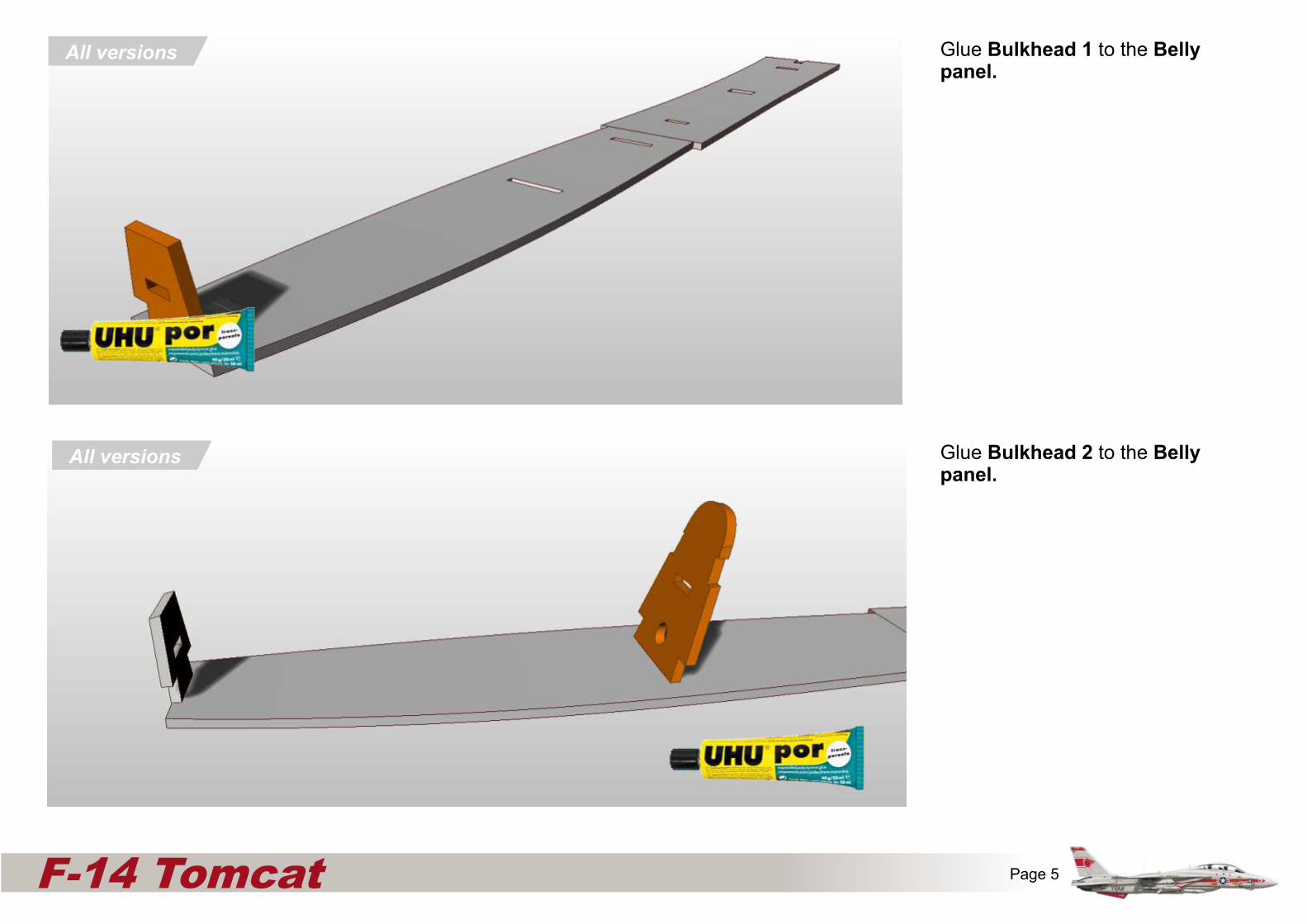
Glue Bulkhead 1 to the Belly panel.
All versions
All versions
x
Fuselage side (Inner)
Fuselage upper corner reinforcers
6mm
EDF only
All versions
Pusher Bulkhead 4EDF only
Pusher onlyPARTS ‘CUT AWAY’ FOR ILLUSTRATION PURPOSES
All versions
Page 5F-14 Tomcat
Glue Bulkhead 2 to the Belly panel.
All versions
All versions
x
Fuselage side (Inner)
Fuselage upper corner reinforcers
6mm
EDF only
All versions
Pusher Bulkhead 4EDF only
Pusher onlyPARTS ‘CUT AWAY’ FOR ILLUSTRATION PURPOSES
All versions
Page 6F-14 Tomcat
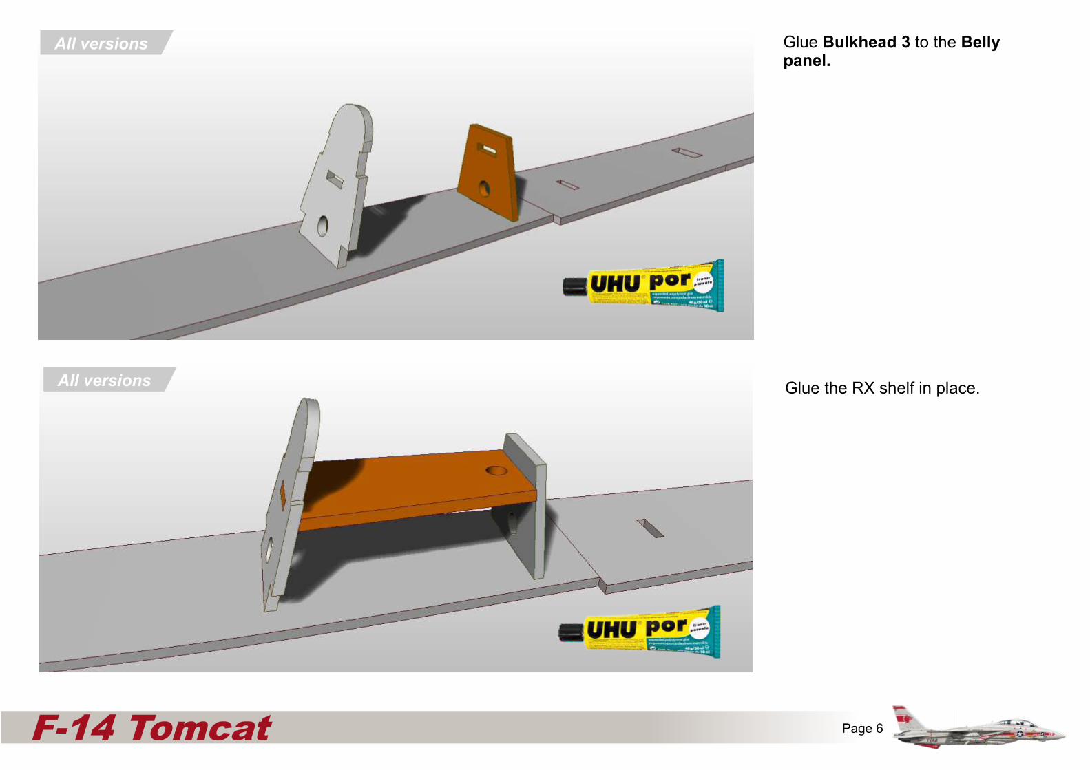
Glue Bulkhead 3 to the Belly panel.
Glue the RX shelf in place.

Glue the Upper corner reinforcers in place as shown.
Locate the front parts 6mm down from the top of Bulkhead 1
All versions
x
Fuselage side (Inner)
Fuselage upper corner reinforcers
6mm
EDF only
All versions
Pusher Bulkhead 4EDF only
Pusher onlyPARTS ‘CUT AWAY’ FOR ILLUSTRATION PURPOSES
All versions
Page 7F-14 Tomcat
Glue Lower corner reinforcers to the Belly panel.
6mm
All versions

Glue the Lower Nosebridge panel in place as shown.
All versions
x
Fuselage side (Inner)
Fuselage upper corner reinforcers
6mm
EDF only
All versions
Pusher Bulkhead 4EDF only
Pusher onlyPARTS ‘CUT AWAY’ FOR ILLUSTRATION PURPOSES
All versions
Page 8F-14 Tomcat
Glue the Magnet panel in placeAll versions
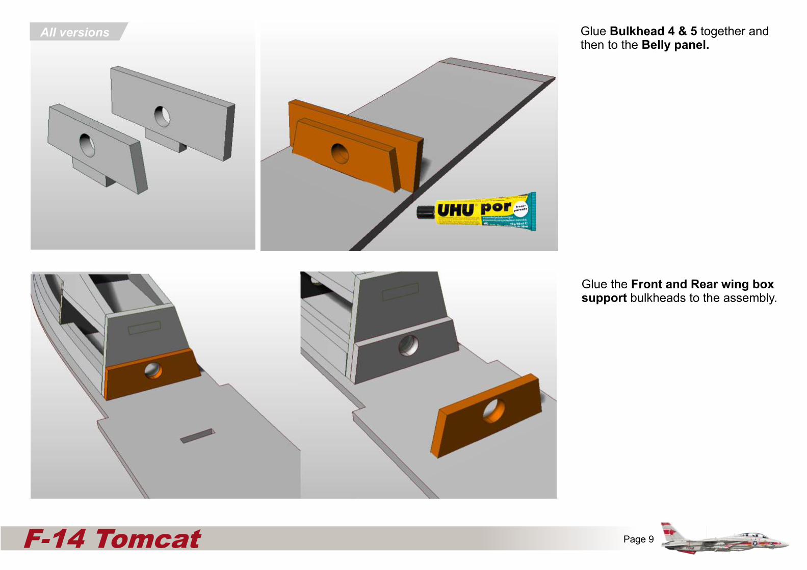
Glue Bulkhead 4 & 5 together and then to the Belly panel.
All versions
Glue the Front and Rear wing box support bulkheads to the assembly.
x
Fuselage side (Inner)
Fuselage upper corner reinforcers
6mm
EDF only
All versions
Pusher Bulkhead 4EDF only
Pusher onlyPARTS ‘CUT AWAY’ FOR ILLUSTRATION PURPOSES
All versions
Page 9F-14 Tomcat
All versions
All versions
x
Fuselage side (Inner)
Fuselage upper corner reinforcers
6mm
EDF only
All versions
Pusher Bulkhead 4EDF only
Pusher onlyPARTS ‘CUT AWAY’ FOR ILLUSTRATION PURPOSES
All versions
Page 9F-14 Tomcat
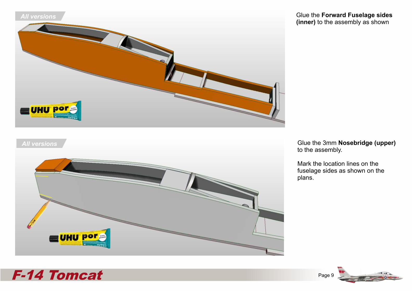
Glue the Forward Fuselage sides (inner) to the assembly as shown
Glue the 3mm Nosebridge (upper) to the assembly.
Mark the location lines on the fuselage sides as shown on the plans.

Glue the Forward fuselage sides (outer) to the assembly.
All versionsx
Fuselage side (Inner)
Fuselage upper corner reinforcers
6mm
EDF only
All versions
Pusher Bulkhead 4EDF only
Pusher onlyPARTS ‘CUT AWAY’ FOR ILLUSTRATION PURPOSES
All versions
Page 11F-14 Tomcat
Create either a 3d printed Nosecone or one consisting of layers of foam sanded to get the right shape, by removing the ‘mountains’ until the ‘valleys’ are no more.
All versions
3DPrinted
Part
3DPrinted
Part(optional)
Mountain
Valley
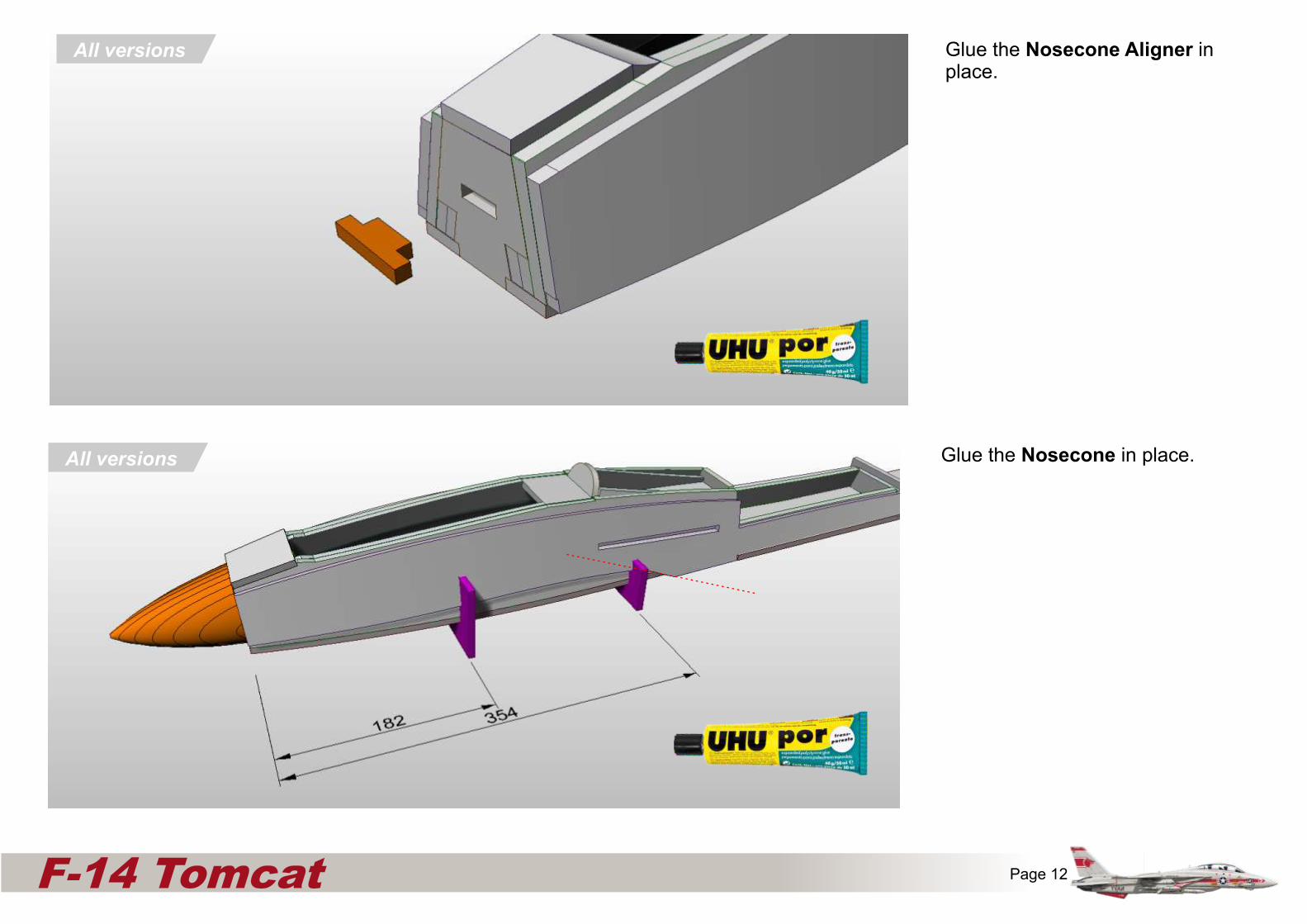
Glue the Nosecone Aligner in place.
All versionsx
Fuselage side (Inner)
Fuselage upper corner reinforcers
6mm
EDF only
All versions
Pusher Bulkhead 4EDF only
Pusher onlyPARTS ‘CUT AWAY’ FOR ILLUSTRATION PURPOSES
All versions
Page 12F-14 Tomcat
All versions Glue the Nosecone in place.
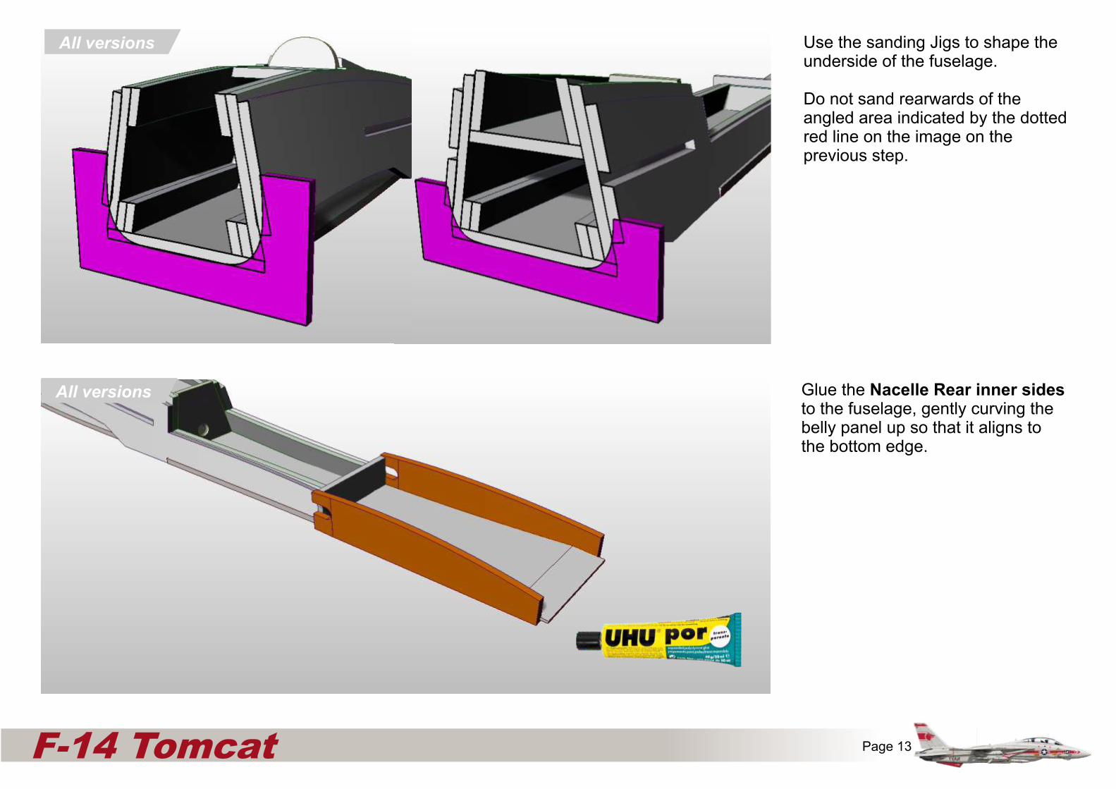
Use the sanding Jigs to shape the underside of the fuselage.
Do not sand rearwards of the angled area indicated by the dotted red line on the image on the previous step.
x
Fuselage side (Inner)
Fuselage upper corner reinforcers
6mm
EDF only
All versions
Pusher Bulkhead 4EDF only
Pusher onlyPARTS ‘CUT AWAY’ FOR ILLUSTRATION PURPOSES
All versions
Page 13F-14 Tomcat
All versions
Glue the Nacelle Rear inner sides to the fuselage, gently curving the belly panel up so that it aligns to the bottom edge.
All versions

Glue the two transversal wingbox webs to the lower wingbox piece ensuring that the tabs are facing down (as shown)
All versions
x
Fuselage side (Inner)
Fuselage upper corner reinforcers
6mm
EDF only
All versions
Pusher Bulkhead 4EDF only
Pusher onlyPARTS ‘CUT AWAY’ FOR ILLUSTRATION PURPOSES
All versions
Page 14F-14 Tomcat
Glue the two Forward swing mechanism decks to the assembly

Glue the two lower wingbox reinforcer pieces to the assembly.
All versions
x
Fuselage side (Inner)
Fuselage upper corner reinforcers
6mm
EDF only
All versions
Pusher Bulkhead 4EDF only
Pusher onlyPARTS ‘CUT AWAY’ FOR ILLUSTRATION PURPOSES
All versions
Page 15F-14 Tomcat
Glue the Servo tray to the wing box. (underside shown)
All versions

Glue the two Upper wingbox piece to the assembly.
All versions
x
Fuselage side (Inner)
Fuselage upper corner reinforcers
6mm
EDF only
All versions
Pusher Bulkhead 4EDF only
Pusher onlyPARTS ‘CUT AWAY’ FOR ILLUSTRATION PURPOSES
All versions
Page 16F-14 Tomcat
Glue the two End Webs to the wing box.
All versions

All versions
x
Fuselage side (Inner)
Fuselage upper corner reinforcers
6mm
EDF only
All versions
Pusher Bulkhead 4EDF only
Pusher onlyPARTS ‘CUT AWAY’ FOR ILLUSTRATION PURPOSES
All versions
Page 17F-14 Tomcat
Glue the Wing Hinge layers 1 and 2 together
All versions
Glue the Wing Hinge layers 3 and 4 to the assembly.
3DPrinted
Part
3DPrinted
Part(optional)

All versions
x
Fuselage side (Inner)
Fuselage upper corner reinforcers
6mm
EDF only
All versions
Pusher Bulkhead 4EDF only
Pusher onlyPARTS ‘CUT AWAY’ FOR ILLUSTRATION PURPOSES
All versions
Page 18F-14 Tomcat
Mark the position, but do not cut the ailerons/flaps from the wing until after the aerofoil shaping.
Glue the two Wing parts together. note that only one (lower) has the slot for the carbon spar.
Don't cut out the areas in red until after the aerofoil has been created otherwise it is easy to damage the protruding 'spikes'.
All versions
Using a long flat block with sandpaper attached, carefully shape the wing. There should remain 2mm of untouched depron at the leading and trailing edge of the wing.
Use the Aerofoil shape jigs aligned to the bottom of the servo hole and the end of the flap/aileron to guide you.
All versions
x
Fuselage side (Inner)
Fuselage upper corner reinforcers
6mm
EDF only
All versions
Pusher Bulkhead 4EDF only
Pusher onlyPARTS ‘CUT AWAY’ FOR ILLUSTRATION PURPOSES
All versions
Page 19F-14 Tomcat
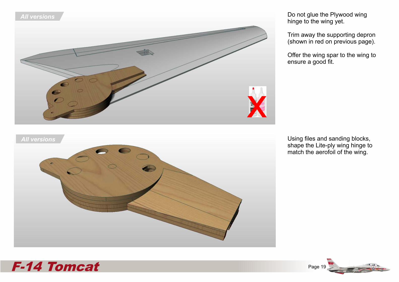
Do not glue the Plywood wing hinge to the wing yet.
Trim away the supporting depron (shown in red on previous page).
Offer the wing spar to the wing to ensure a good fit.
All versions
Using files and sanding blocks, shape the Lite-ply wing hinge to match the aerofoil of the wing.
x

All versions
x
Fuselage side (Inner)
Fuselage upper corner reinforcers
6mm
EDF only
All versions
Pusher Bulkhead 4EDF only
Pusher onlyPARTS ‘CUT AWAY’ FOR ILLUSTRATION PURPOSES
All versions
Page 20F-14 Tomcat
Glue the Plywood wing spar to the wing using epoxy, along with the 6mm carbon fibre tube, using masking tape to hold the glue within the slot.
Turn the right way around and lay flat so that all the bottom surfaces are aligned and totally flat. Ensure that the wing hinge is tight to the wing, and let the glue set.
All versions
Fit a 10mm wide 9g servo to the wing. Try to position the so that the servo hole can be filled and sanded on the top of the wing making the servo 'disappear' from above.
Run the servo cable through the wing spar.
3DPrinted
Part
3DPrinted
Part(optional)
Page 21F-14 Tomcat
All versions
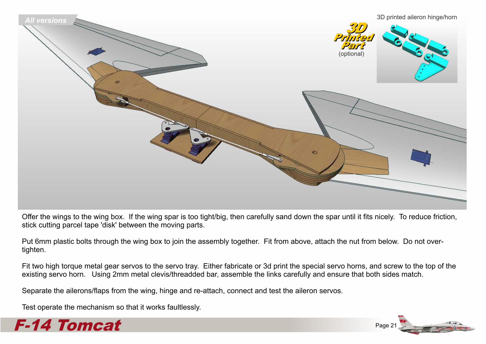
Offer the wings to the wing box. If the wing spar is too tight/big, then carefully sand down the spar until it fits nicely. To reduce friction, stick cutting parcel tape 'disk' between the moving parts.
Put 6mm plastic bolts through the wing box to join the assembly together. Fit from above, attach the nut from below. Do not over-tighten.
Fit two high torque metal gear servos to the servo tray. Either fabricate or 3d print the special servo horns, and screw to the top of the existing servo horn. Using 2mm metal clevis/threadded bar, assemble the links carefully and ensure that both sides match.
Separate the ailerons/flaps from the wing, hinge and re-attach, connect and test the aileron servos.
Test operate the mechanism so that it works faultlessly.
3DPrinted
Part
3DPrinted
Part(optional)
3D printed aileron hinge/horn
x
Fuselage side (Inner)
Fuselage upper corner reinforcers
6mm
EDF only
All versions
Pusher Bulkhead 4EDF only
Pusher onlyPARTS ‘CUT AWAY’ FOR ILLUSTRATION PURPOSES
All versions
Page 22F-14 Tomcat
All versions
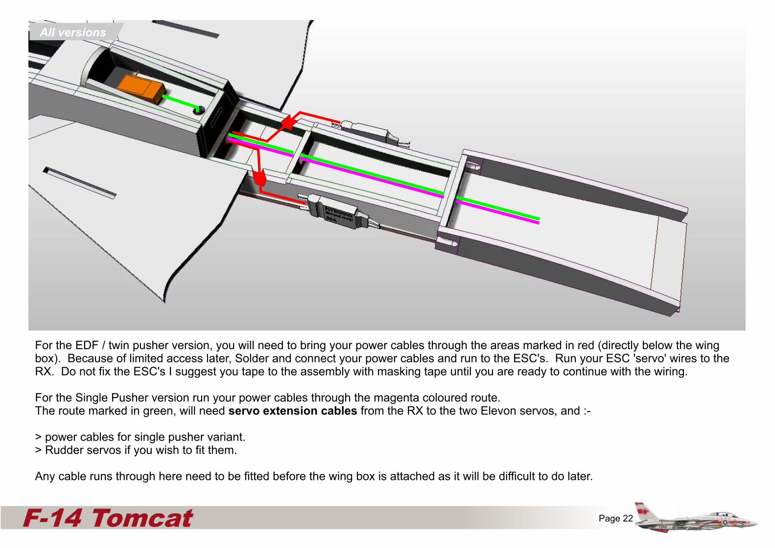
For the EDF / twin pusher version, you will need to bring your power cables through the areas marked in red (directly below the wing box). Because of limited access later, Solder and connect your power cables and run to the ESC's. Run your ESC 'servo' wires to the RX. Do not fix the ESC's I suggest you tape to the assembly with masking tape until you are ready to continue with the wiring.
For the Single Pusher version run your power cables through the magenta coloured route. The route marked in green, will need servo extension cables from the RX to the two Elevon servos, and :-
> power cables for single pusher variant.> Rudder servos if you wish to fit them.
Any cable runs through here need to be fitted before the wing box is attached as it will be difficult to do later.

Dry fit the wing box to the assembly to check/adjust fit, then glue (sparingly) the wingbox to the fuselage.
Be very careful not to get any epoxy on the swinging wing spars.
Connect servo extension cables to the aileron/flap servo and carefully run around the rear of the moving linkages, and cut a way through the bulkhead into the servo tray area.
All versionsx
Fuselage side (Inner)
Fuselage upper corner reinforcers
6mm
EDF only
All versions
Pusher Bulkhead 4EDF only
Pusher onlyPARTS ‘CUT AWAY’ FOR ILLUSTRATION PURPOSES
All versions
Page 23F-14 Tomcat
Dry fit the Rear swing mechanism Deck to the assembly to check/adjust fit, then glue (sparingly) in place.
Be very careful not to get any epoxy on the swinging wing spars.
Once the glue has set, check that the mechanism is working freely.
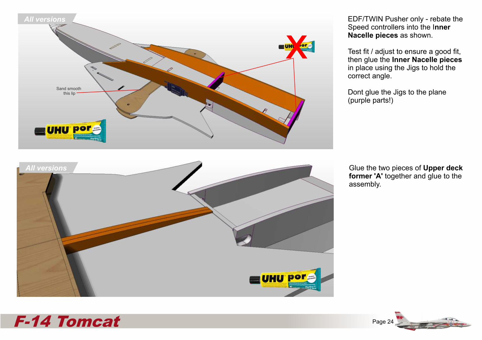
EDF/TWIN Pusher only - rebate the Speed controllers into the Inner Nacelle pieces as shown.
Test fit / adjust to ensure a good fit, then glue the Inner Nacelle pieces in place using the Jigs to hold the correct angle.
Dont glue the Jigs to the plane (purple parts!)
All versions
Glue the two pieces of Upper deck former 'A' together and glue to the assembly.
All versions
x
Fuselage side (Inner)
Fuselage upper corner reinforcers
6mm
EDF only
All versions
Pusher Bulkhead 4EDF only
Pusher onlyPARTS ‘CUT AWAY’ FOR ILLUSTRATION PURPOSES
All versions
Page 24F-14 Tomcat
xSand smooth
this lip
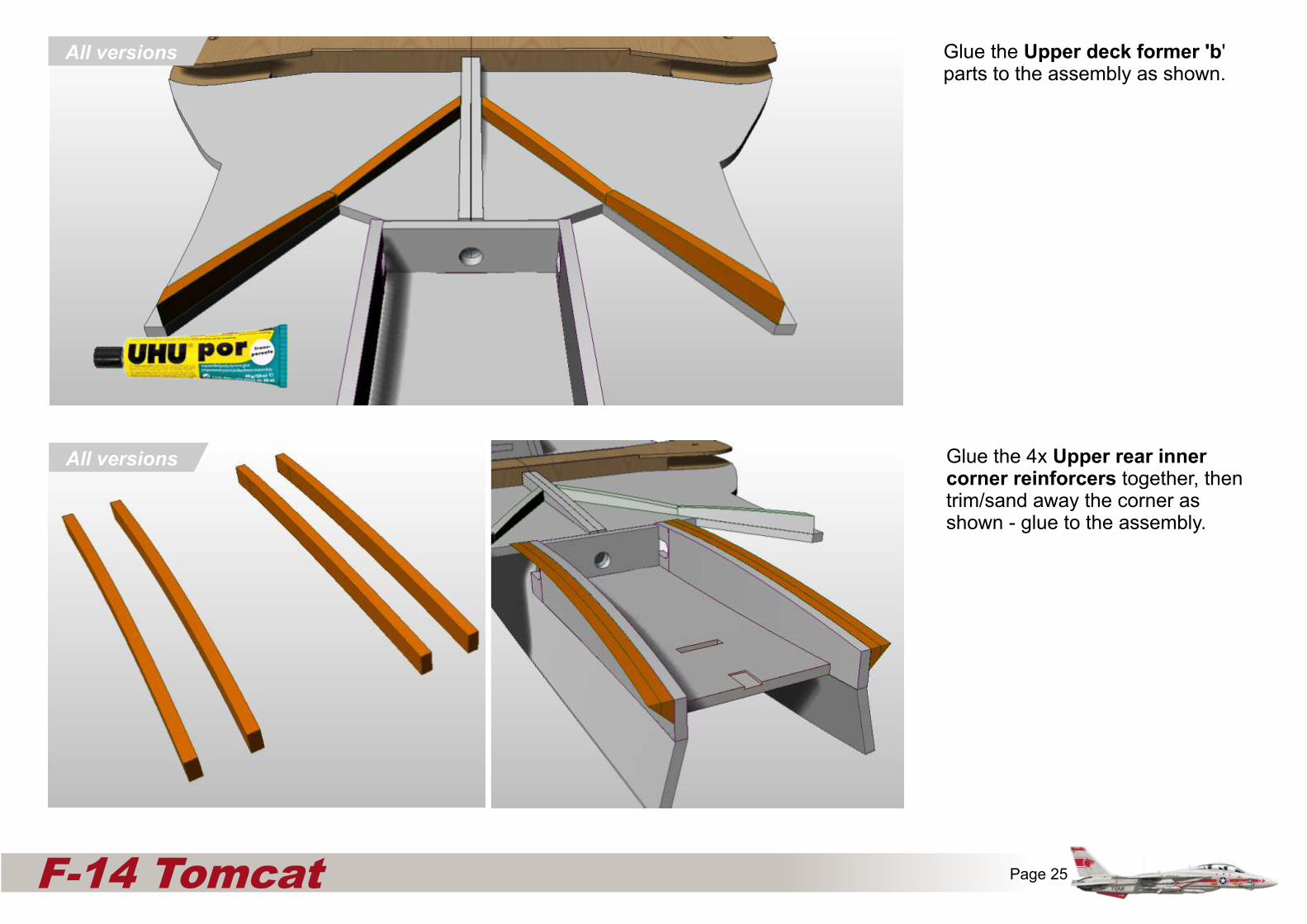
Glue the Upper deck former 'b' parts to the assembly as shown.
All versions
Glue the 4x Upper rear inner corner reinforcers together, then trim/sand away the corner as shown - glue to the assembly.
All versions
x
Fuselage side (Inner)
Fuselage upper corner reinforcers
6mm
EDF only
All versions
Pusher Bulkhead 4EDF only
Pusher onlyPARTS ‘CUT AWAY’ FOR ILLUSTRATION PURPOSES
All versions
Page 25F-14 Tomcat
All versions

Gently curve the rear Nacelle upper pieces using the table edge technique and glue to the assembly. Aligning to the Turtledeck former 'b' parts as shown.
x
Fuselage side (Inner)
Fuselage upper corner reinforcers
6mm
EDF only
All versions
Pusher Bulkhead 4EDF only
Pusher onlyPARTS ‘CUT AWAY’ FOR ILLUSTRATION PURPOSES
All versions
Page 26F-14 Tomcat
EDF only Gently curve the rear Nacelle upper pieces using the table edge technique and glue to the assembly. Aligning to the Turtledeck former 'b' parts as shown.
Both Pusher variants only

Glue the two pieces of the Elevon servo/motor mount together and then glue into the slot, the motor mount.
Hobbyking - OR004- 00602
There are 3d print versions available - see website.
x
Fuselage side (Inner)
Fuselage upper corner reinforcers
6mm
EDF only
All versions
Pusher Bulkhead 4EDF only
Pusher onlyPARTS ‘CUT AWAY’ FOR ILLUSTRATION PURPOSES
All versions
Page 27F-14 Tomcat
Dry-fit the two Elevon servo/motor mounts to the Upper rear nacelle.
These are to remain unglued for access purposes until the Nacelle belly panels are attached.
3DPrinted
Part
3DPrinted
Part(optional)
x
Twin Pusher onlySingle Pusher only
Both Pusher variants only
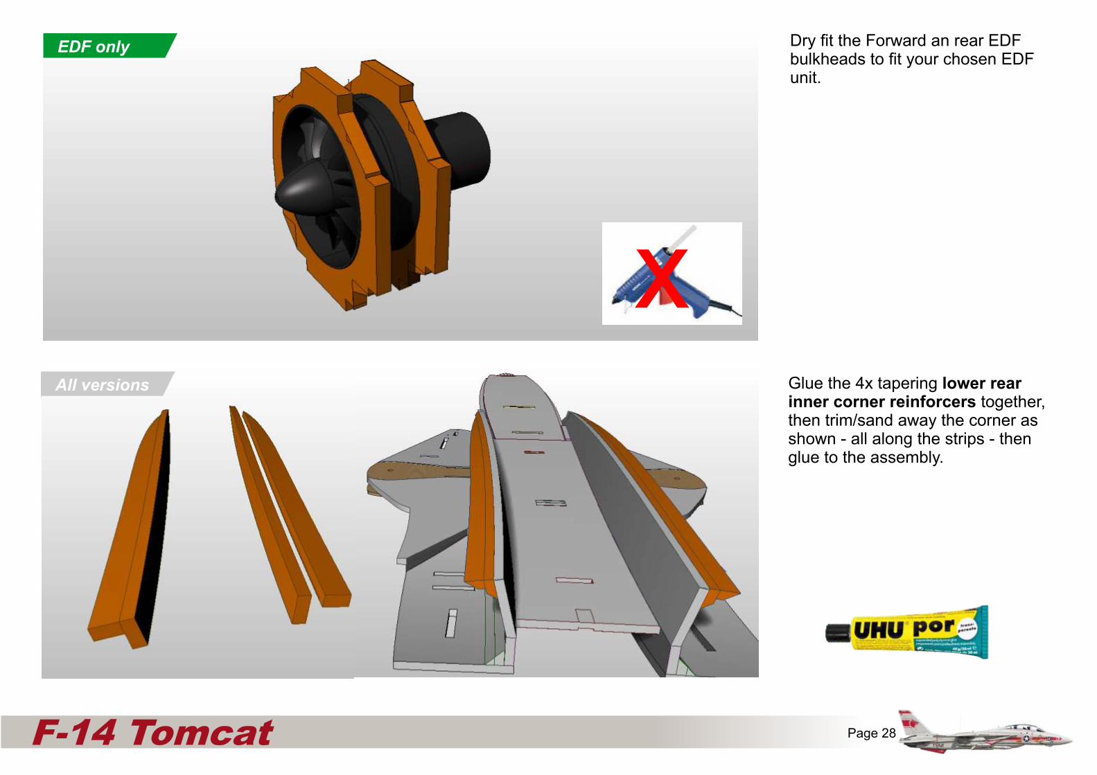
Dry fit the Forward an rear EDF bulkheads to fit your chosen EDF unit.x
Fuselage side (Inner)
Fuselage upper corner reinforcers
6mm
EDF only
All versions
Pusher Bulkhead 4EDF only
Pusher onlyPARTS ‘CUT AWAY’ FOR ILLUSTRATION PURPOSES
All versions
Page 28F-14 Tomcat
EDF only
xAll versions Glue the 4x tapering lower rear
inner corner reinforcers together, then trim/sand away the corner as shown - all along the strips - then glue to the assembly.
All versions

Page 29F-14 Tomcat
EDF only
All versions Gently bend the Upper rear Outer corner reinforcers to match the shape of the upper nacelle top, then glue the pieces together. Note the different widths.
Trim/sand away the corner as shown - all along each strip - then glue to the assembly as shown.
Trim away the slots in the inner Nacelle area to locate the EDF mount (as per plans).
Dry fit the EDF assemblies into the fuselage. This is for access purposes.
x
All versions

x
Fuselage side (Inner)
Fuselage upper corner reinforcers
6mm
EDF only
All versions
Pusher Bulkhead 4EDF only
Pusher onlyPARTS ‘CUT AWAY’ FOR ILLUSTRATION PURPOSES
All versions
Page 30F-14 Tomcat
Glue the motor mounts to the fuselage using UHU Por.
Test fit the elevon servos to the pusher motor / elevon servo mounts and glue in place using hot melt glue.
Drill out standard sizes servo horns and dry-fit to the 6mm carbon elevon shaft.
Connect these control horns together using piano wire - ensure a slop free fitting - I suggest Ball links or similar.
Fabricate the the Elevon support bracket using 3mm liteply and aluminium tubing (size so it snugly fits around the carbon spar) and glue in place (both sides)
Both Pusher variants only
3DPrinted
Part
3DPrinted
Part(optional)
Both Pusher variants only

x
Fuselage side (Inner)
Fuselage upper corner reinforcers
6mm
EDF only
All versions
Pusher Bulkhead 4EDF only
Pusher onlyPARTS ‘CUT AWAY’ FOR ILLUSTRATION PURPOSES
All versions
Page 31F-14 Tomcat
Glue the EDF bulkheads as well as the Exhaust bulkheads to the assembly using UHU por.
Glue the EDF units into the bulkheads using hot melt glue or silicone sealant (to reduce edf noise)
Glue the exhaust bulkheads to the fuselage using UHU por. Construct the thrust tube using thin sheet plastic, joining the edges together using nylon reinforced tape.
Glue the thrust tube in place using hot melt glue - carefully as it can melt plastic sheet - test this on scrap first.
Glue both ESCs to the inner Nacelle and solder the motor to ESC cables together.
Connect the cables from the ESC to the RX and ensure the motors are running the right way.
Connect the elevon servos to the RX and check that they are setup well.
EDF only
Twin Pusher only

x
Fuselage side (Inner)
Fuselage upper corner reinforcers
6mm
EDF only
All versions
Pusher Bulkhead 4EDF only
Pusher onlyPARTS ‘CUT AWAY’ FOR ILLUSTRATION PURPOSES
All versions
Page 32F-14 Tomcat
3d print the air intakes. Recess the motor wires into the inner nacelle depron so they run behind the intakes.
If you don't have access to a 3D printer, create something similar using 3mm depron sheet, glued and taped together.
If you don't create this, then ensure you leave the Bell mouth on the EDF units to maximise airflow efficiency.
Recess and Glue both ESCs to the inner Nacelle and connect all the motor cables to ensure the motors are running the right way.
Recess the EDF motor cables into the nacelle sides then through the hole shown into the central fuselage cavity.
Make a hole through back through the inner Nacelle through the thrust tube to the motor.
EDF only
EDF only
3DPrinted
Part
3DPrinted
Part(optional)
x
Fuselage side (Inner)
Fuselage upper corner reinforcers
6mm
EDF only
All versions
Pusher Bulkhead 4EDF only
Pusher onlyPARTS ‘CUT AWAY’ FOR ILLUSTRATION PURPOSES
All versions
Page 33F-14 Tomcat
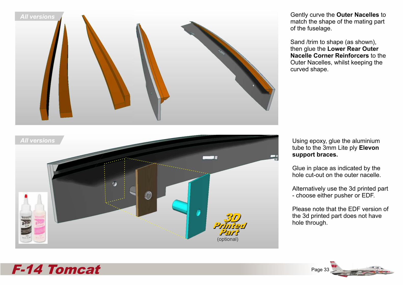
Gently curve the Outer Nacelles to match the shape of the mating part of the fuselage.
Sand /trim to shape (as shown), then glue the Lower Rear Outer Nacelle Corner Reinforcers to the Outer Nacelles, whilst keeping the curved shape.
All versions
Using epoxy, glue the aluminium tube to the 3mm Lite ply Elevon support braces.
Glue in place as indicated by the hole cut-out on the outer nacelle.
Alternatively use the 3d printed part - choose either pusher or EDF.
Please note that the EDF version of the 3d printed part does not have hole through.3D
PrintedPart
3DPrinted
Part(optional)
All versions

x
Fuselage side (Inner)
Fuselage upper corner reinforcers
6mm
EDF only
All versions
Pusher Bulkhead 4EDF only
Pusher onlyPARTS ‘CUT AWAY’ FOR ILLUSTRATION PURPOSES
All versions
Page 34F-14 Tomcat
Glue the Exhaust bulkheads in place as shown.
Using the Nacelle Jig, and temporarily using the exhaust bulkhead, Glue the outer Nacelle assembly to the model.
Both Pusher variants only
Both Pusher variants only
x
Fuselage side (Inner)
Fuselage upper corner reinforcers
6mm
EDF only
All versions
Pusher Bulkhead 4EDF only
Pusher onlyPARTS ‘CUT AWAY’ FOR ILLUSTRATION PURPOSES
All versions
Page 35F-14 Tomcat
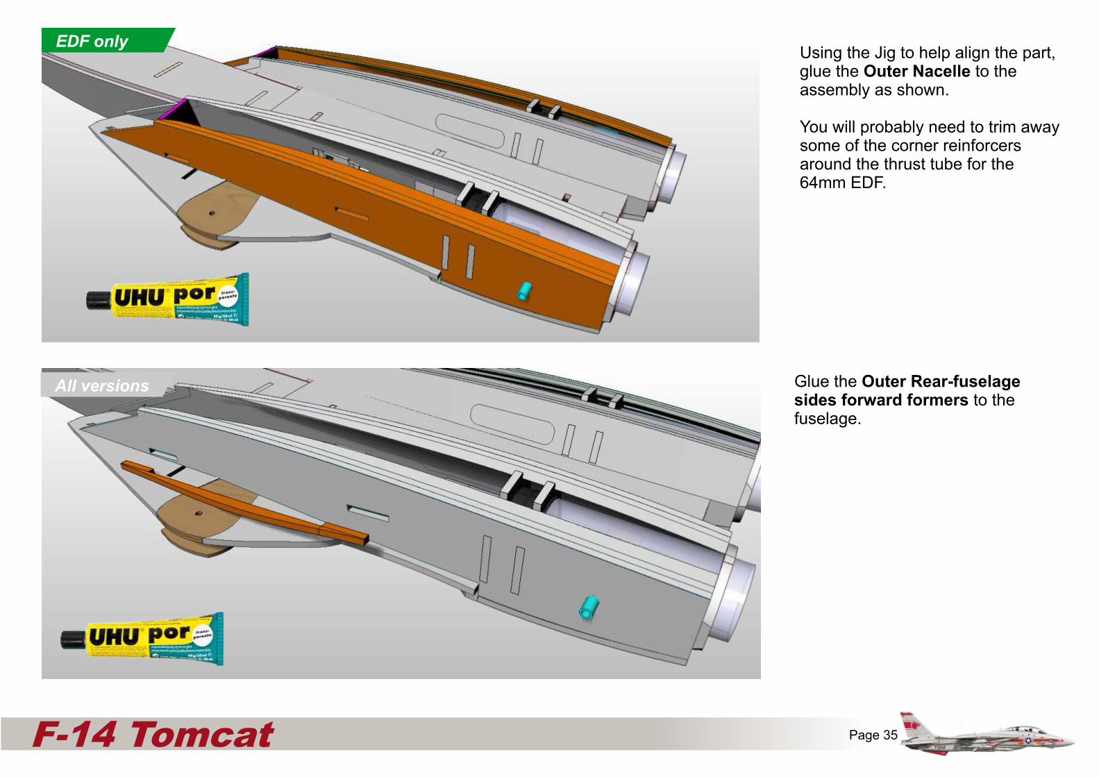
Glue the Outer Rear-fuselage sides forward formers to the fuselage.
Using the Jig to help align the part, glue the Outer Nacelle to the assembly as shown.
You will probably need to trim away some of the corner reinforcers around the thrust tube for the 64mm EDF.
EDF only
All versions
All versions
All versions
x
Fuselage side (Inner)
Fuselage upper corner reinforcers
6mm
EDF only
All versions
Pusher Bulkhead 4EDF only
Pusher onlyPARTS ‘CUT AWAY’ FOR ILLUSTRATION PURPOSES
All versions
Page 36F-14 Tomcat
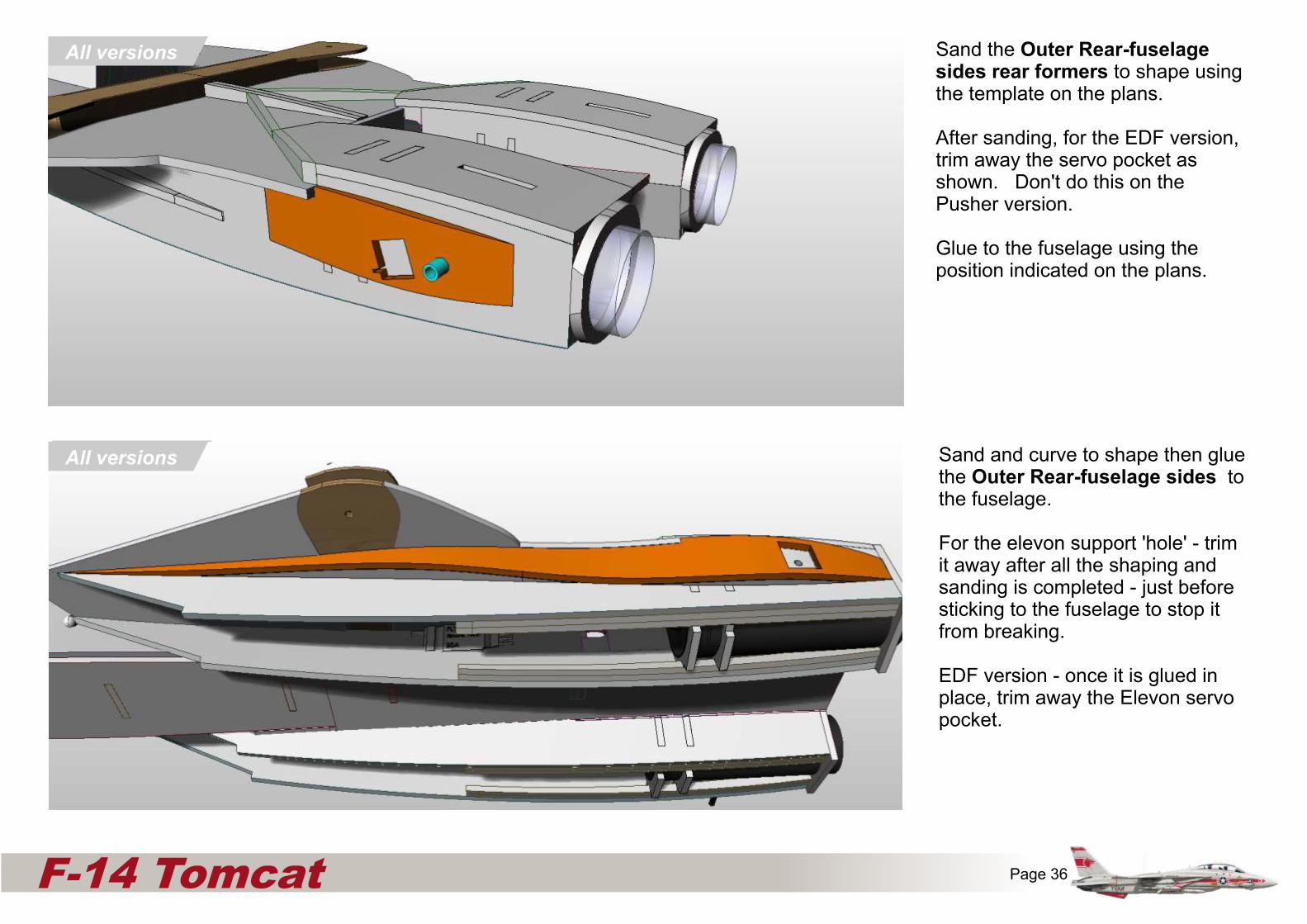
Sand the Outer Rear-fuselage sides rear formers to shape using the template on the plans.
After sanding, for the EDF version, trim away the servo pocket as shown. Don't do this on the Pusher version.
Glue to the fuselage using the position indicated on the plans.
All versions Sand and curve to shape then glue the Outer Rear-fuselage sides to the fuselage.
For the elevon support 'hole' - trim it away after all the shaping and sanding is completed - just before sticking to the fuselage to stop it from breaking.
EDF version - once it is glued in place, trim away the Elevon servo pocket.
Page 37F-14 Tomcat
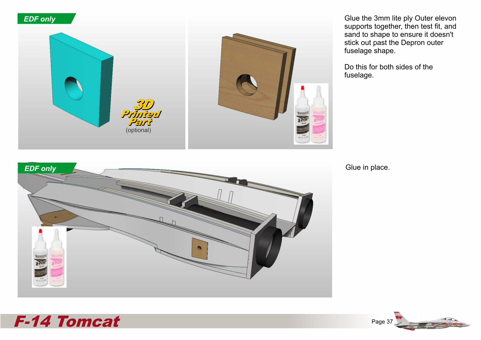
Glue the 3mm lite ply Outer elevon supports together, then test fit, and sand to shape to ensure it doesn't stick out past the Depron outer fuselage shape.
Do this for both sides of the fuselage.
Glue in place.
3DPrinted
Part
3DPrinted
Part(optional)
EDF only
EDF only

x
Fuselage side (Inner)
Fuselage upper corner reinforcers
6mm
EDF only
All versions
Pusher Bulkhead 4EDF only
Pusher onlyPARTS ‘CUT AWAY’ FOR ILLUSTRATION PURPOSES
All versions
Page 38F-14 Tomcat
Drill and DRY FIT the aluminium tube into the plywood outer fuselage elevon support block using epoxy.
Ensure that the carbon tube is horizontal. Lay the fuselage on its back on a flat surface and make a jig to ensure that it is correct. If you need to adjust the the angle, then drill the plywood with a slightly bigger hole to allow the aluminium outer tube to move. Once Horizontal is achieved, then use epoxy to glue the tube to the ply.
Ensure no glue gets inside the tube.
Drill-out Prop adaptors to get a nice tight fit to the carbon tube.
Slide the Carbon Elevon shaft into the assembly, adding prop adaptor, Servo Horn and Prop adaptor.
Then slide them around to get the best positions to stop the elevon spar from rattling, but allowing it to rotate. Glue the servo horn to the Elevon shaft with CA glue.
Allow the aluminiumtube to protrude 3mm
Both Pusher variants only
Both Pusher variants only

x
Fuselage side (Inner)
Fuselage upper corner reinforcers
6mm
EDF only
All versions
Pusher Bulkhead 4EDF only
Pusher onlyPARTS ‘CUT AWAY’ FOR ILLUSTRATION PURPOSES
All versions
Page 39F-14 Tomcat
Glue the Nacelle belly pieces to the fuselage.
Slide another drilled out prop adaptor onto the carbon elevon shaft to prevent glue entering the aluminium tube, and to act as a bushing.
Turn on your plane / transmitter, and ensure your servos are without trim, and are correct.
Then Using two strips of masking tape and epoxy, glue the elevons to the carbon shaft. Use piles of books to help you to raise two areas directly below the elevons, to allow the elevons to be supported while the glue sets.
Both Pusher variants only
Both Pusher variants only

x
Fuselage side (Inner)
Fuselage upper corner reinforcers
6mm
EDF only
All versions
Pusher Bulkhead 4EDF only
Pusher onlyPARTS ‘CUT AWAY’ FOR ILLUSTRATION PURPOSES
All versions
Page 40F-14 Tomcat
Dry fit the belly Nacelle to the assembly in order to hold the outer Nacelle in place.
Cut the shaft to length and then offer it in place.
Build a simple support jig in order to cradle the carbon shaft (EDF) in place - in both longitudinal and latitudinal horizontal axes.
If their is any need to reposition the shafts - then drill out the hole and and re-set the spar using epoxy.fer it in place.
EDF only
3DPrinted
Part
3DPrinted
Part(optional)
Cut to length and glue the aluminium Tube into the dedicated area within the slot in the Elevons as shown.
Temporarily block the inside ends of the tube to prevent glue ingress. Use masking tape to support the tube while the glue sets.
EDF only
x
Fuselage side (Inner)
Fuselage upper corner reinforcers
6mm
EDF only
All versions
Pusher Bulkhead 4EDF only
Pusher onlyPARTS ‘CUT AWAY’ FOR ILLUSTRATION PURPOSES
All versions
Page 41F-14 Tomcat
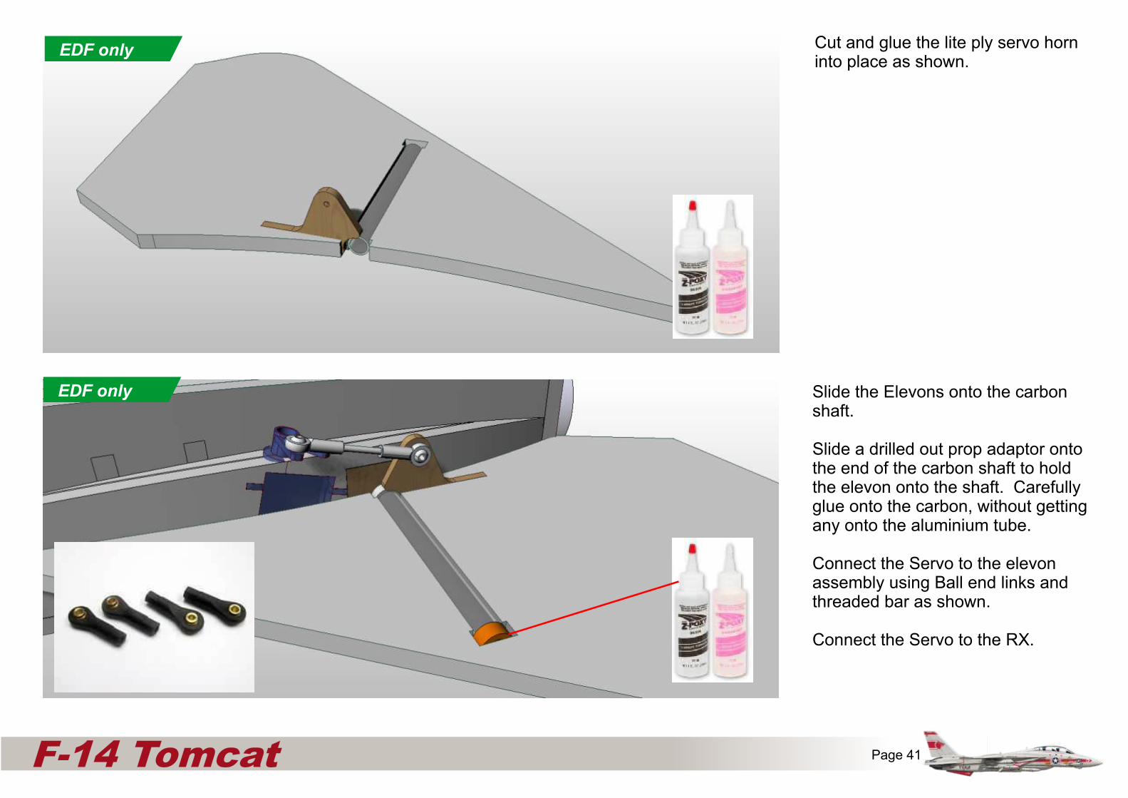
Cut and glue the lite ply servo horn into place as shown.
EDF only
Slide the Elevons onto the carbon shaft.
Slide a drilled out prop adaptor onto the end of the carbon shaft to hold the elevon onto the shaft. Carefully glue onto the carbon, without getting any onto the aluminium tube.
Connect the Servo to the elevon assembly using Ball end links and threaded bar as shown.
Connect the Servo to the RX.
EDF only
Page 42F-14 Tomcat
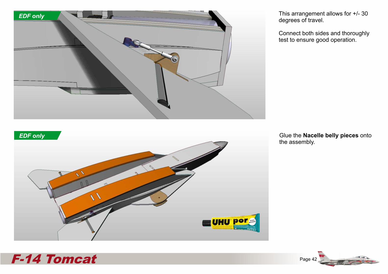
This arrangement allows for +/- 30 degrees of travel.
Connect both sides and thoroughly test to ensure good operation.
EDF only
Glue the Nacelle belly pieces onto the assembly.
EDF only

GLOVE VANE ASSEMBLY
This was an early design feature of the F-14a Tomcat, and was removed on later versions. It helped with supersonic handling and balancing the CG with the wings swept back. It is optional on this model.
Trim a cocktail stick to 20mm. Glue into the place marked on the plans so that there is 12mm remaining.
All versions
Page 43F-14 Tomcat
All versions
OPTIONAL
GLOVE VANE ASSEMBLY
Fit the 0.5mm glove vane washer over the cocktail stick.
Alternatively use 3mm stainless washers.
3DPrinted
Part
3DPrinted
Part(optional)
All versionsAll versions

Page 44F-14 Tomcat
GLOVE VANE ASSEMBLY
Cut out the glove vanes from 3mm balsa. reinforcing the hinge areas with a little epoxy/ 0.6oz woven glass fibre to give durability.
Trim away the depron area only where the servo arm collides with it.(Marked in red)
Connect and adjust the clevis/pushrod assembly so that it all works as it should.
All versions OPTIONAL
Single Pusher only SINGLE PUSHER VERSION
Glue the upper and lower single pusher motor mount pieces together using UHU por.
Using Hot Melt Glue, fix the motor mount stick to the depron.

Page 45F-14 Tomcat
Single Pusher only
SINGLE PUSHER VERSION
Glue the upper and lower 3mm liteply motor mount pieces to the assembly as shown.
Single Pusher only
SINGLE PUSHER VERSION
Glue the single pusher support bulkhead in place as shown.
Page 46F-14 Tomcat
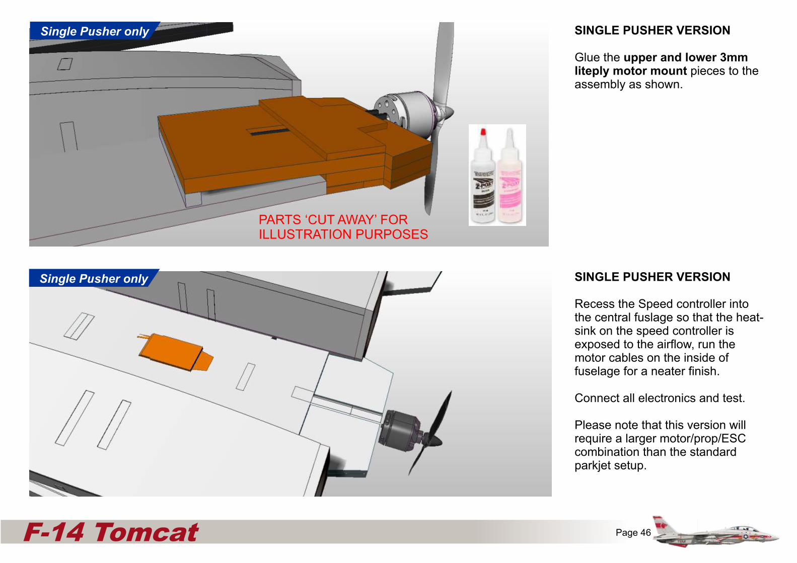
SINGLE PUSHER VERSION
Glue the upper and lower 3mm liteply motor mount pieces to the assembly as shown.
Single Pusher only
PARTS ‘CUT AWAY’ FOR ILLUSTRATION PURPOSES
Single Pusher only SINGLE PUSHER VERSION
Recess the Speed controller into the central fuslage so that the heat-sink on the speed controller is exposed to the airflow, run the motor cables on the inside of fuselage for a neater finish.
Connect all electronics and test.
Please note that this version will require a larger motor/prop/ESC combination than the standard parkjet setup.
Page 47F-14 Tomcat
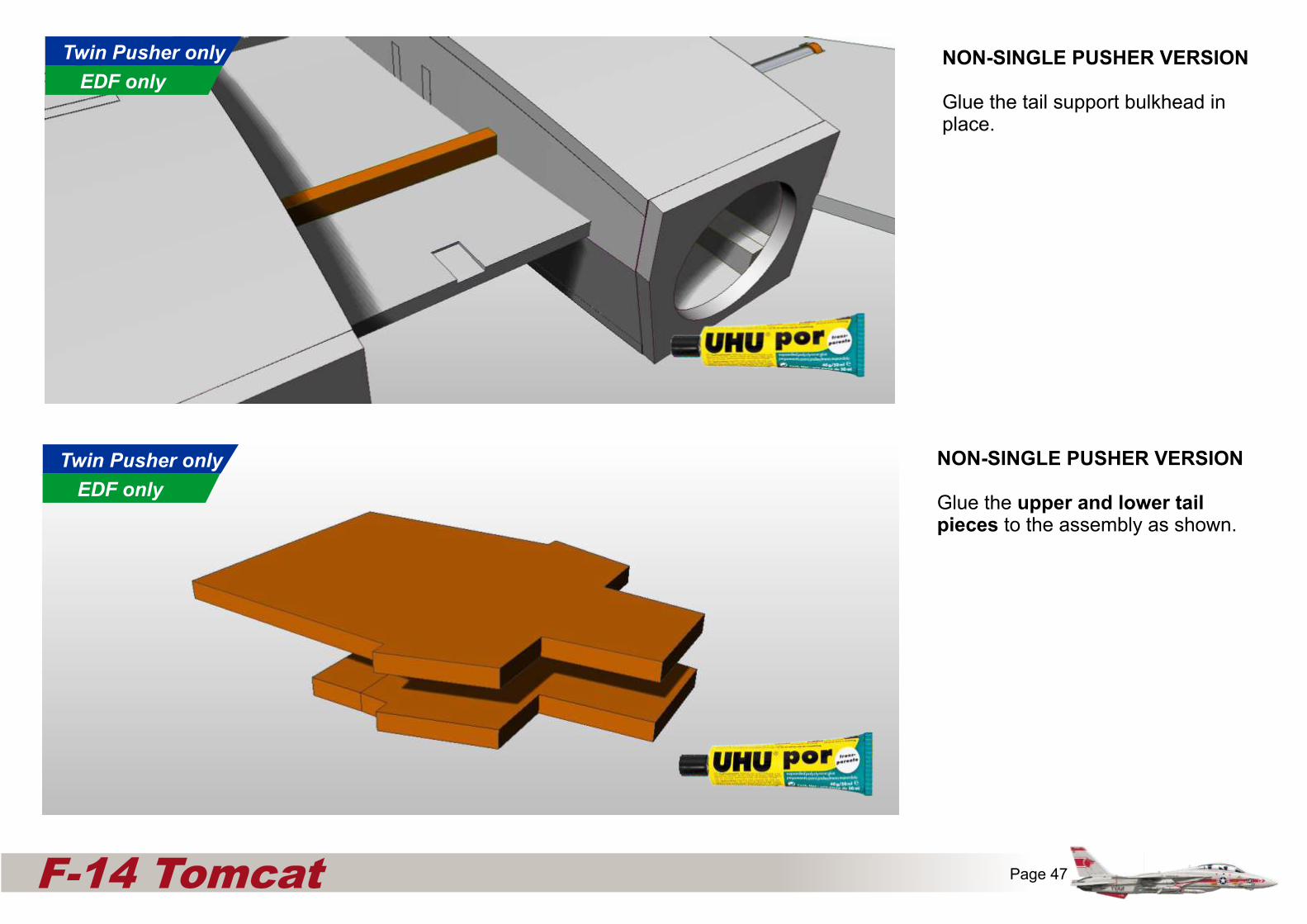
NON-SINGLE PUSHER VERSION
Glue the upper and lower tail pieces to the assembly as shown.
Twin Pusher only
EDF only
NON-SINGLE PUSHER VERSION
Glue the tail support bulkhead in place.
Twin Pusher only
EDF only

Page 48F-14 Tomcat
NON-SINGLE PUSHER VERSION
Glue the tail assembly to the fuselage as shown - ensuring that it is level to the tail support bulkhead as shown.
Twin Pusher only
EDF only
PARTS ‘CUT AWAY’ FOR ILLUSTRATION PURPOSES
All versions Glue the two Upper deck formers 'C' to the assembly. For the EDF version, trim away areas that the EDF motor wires require.

Page 49F-14 Tomcat
All versions
Glue the two Upper deck formers 'D' together then on to the assembly. For the Single pusher version, trim away areas that the ESC / motor wires require.
All versions
Shape then glue the two Upper deck formers 'E' to the assembly.

Page 50F-14 Tomcat
All versions
Glue the two Upper deck formers 'F' to the fuselage. If you are having operational glove vanes, then trim away the rear of the formers to allow pushrod travel.
All versions
Shape then glue the two Upper deck formers 'G' to the assembly.

Page 51F-14 Tomcat
Glue the two Upper deck formers 'H' to the fuselage.
All versions
If you are having operational glove vanes, then trim away the rear of the various formers to allow pushrod travel.
All versions

Page 52F-14 Tomcat
Use M6 x 30mm plastic bolt and nut to fit the wings to the wing box.
Use loc-tite on the nut to prevent it working loose.
Alternatively use the 3D printed wing hinge along with a M4 x 25mm Countersunk socket screw with M4 Nylock nut.
This system requires an 8mm hole in the wing box instead of the 6mm hole.
3DPrinted
Part
3DPrinted
Part(optional)
All versions
All versions

Page 53F-14 Tomcat
All versions
Trim away the Upper deck around the wing box area to ensure a good fit, then apply glue to the green areas (mirrored) and then glue the Upper deck Pieces to the fuselage.
All versions
Sand to shape, then glue the two Upper deck formers 'I' to the wing box assembly as shown.

Page 54F-14 Tomcat
All versions
Gently curve the Upper deck side pieces to match the Upper deck edges.
trim and sand the Upper deck side pieces so both sides sit over the wing box as shown.
Trim the area away over the glove vane (optional) to ensure smooth movement, and allow the cocktail stick 'pin' to push into the side pieces.
Glue in place - to the edge of the Upper deck and to the wingbox.
All versions
Glue the two Upper deck formers 'J' to the assembly as shown. Don't glue to the glove vanes!

Page 55F-14 Tomcat
SINGLE PUSHER VERSION ONLY
Glue the 3mm infill panel into the recess on the top of the fuselage.
Glue the two Turtledeck lower side pieces to the fuselage as shown.
Single Pusher only
All versions

Page 56F-14 Tomcat
Curve the Turtledeck middle piece and glue to the fuselage as shown.
All versions
All versions Glue the two Turtledeck inner side pieces to the fuselage as shown.
I recommend at this stage, to run a servo extension cable from your 'binding channel' (if your radio system works this way), through to the battery compartment in order to simplify re-binding if your receiver ever loses its bind.
Page 57F-14 Tomcat
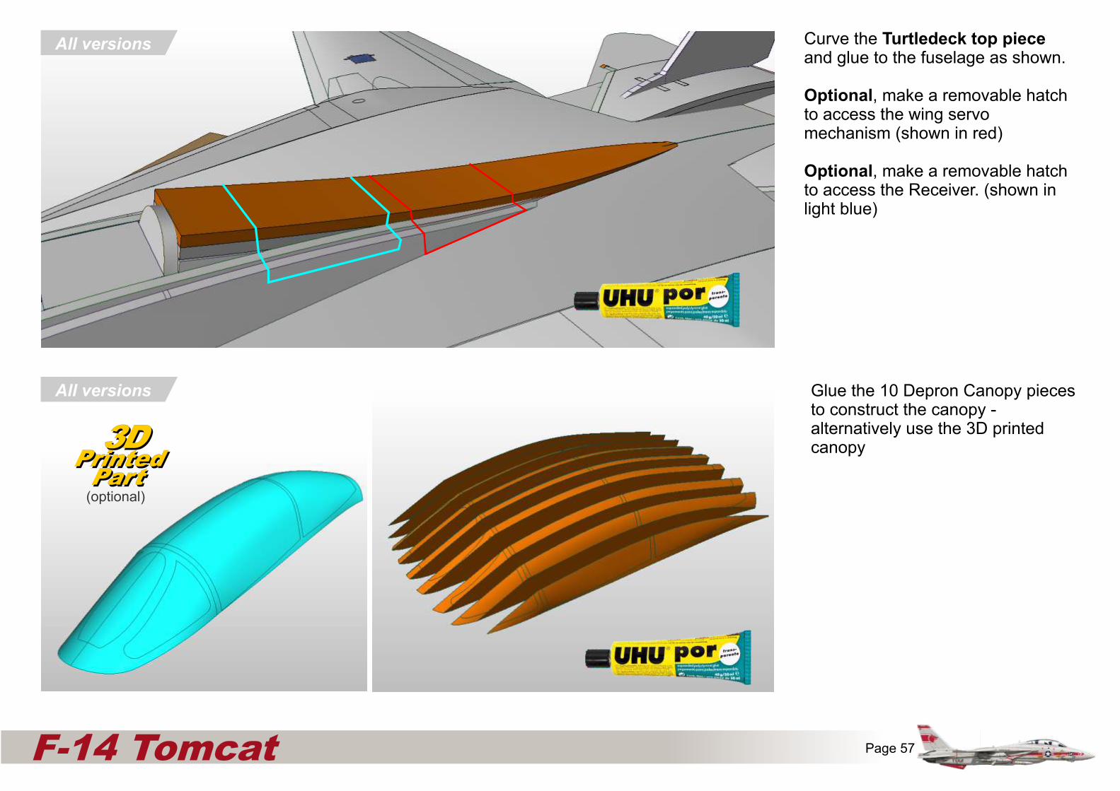
Glue the 10 Depron Canopy pieces to construct the canopy - alternatively use the 3D printed canopy
All versions
All versions Curve the Turtledeck top piece and glue to the fuselage as shown.
Optional, make a removable hatch to access the wing servo mechanism (shown in red)
Optional, make a removable hatch to access the Receiver. (shown in light blue)
3DPrinted
Part
3DPrinted
Part(optional)
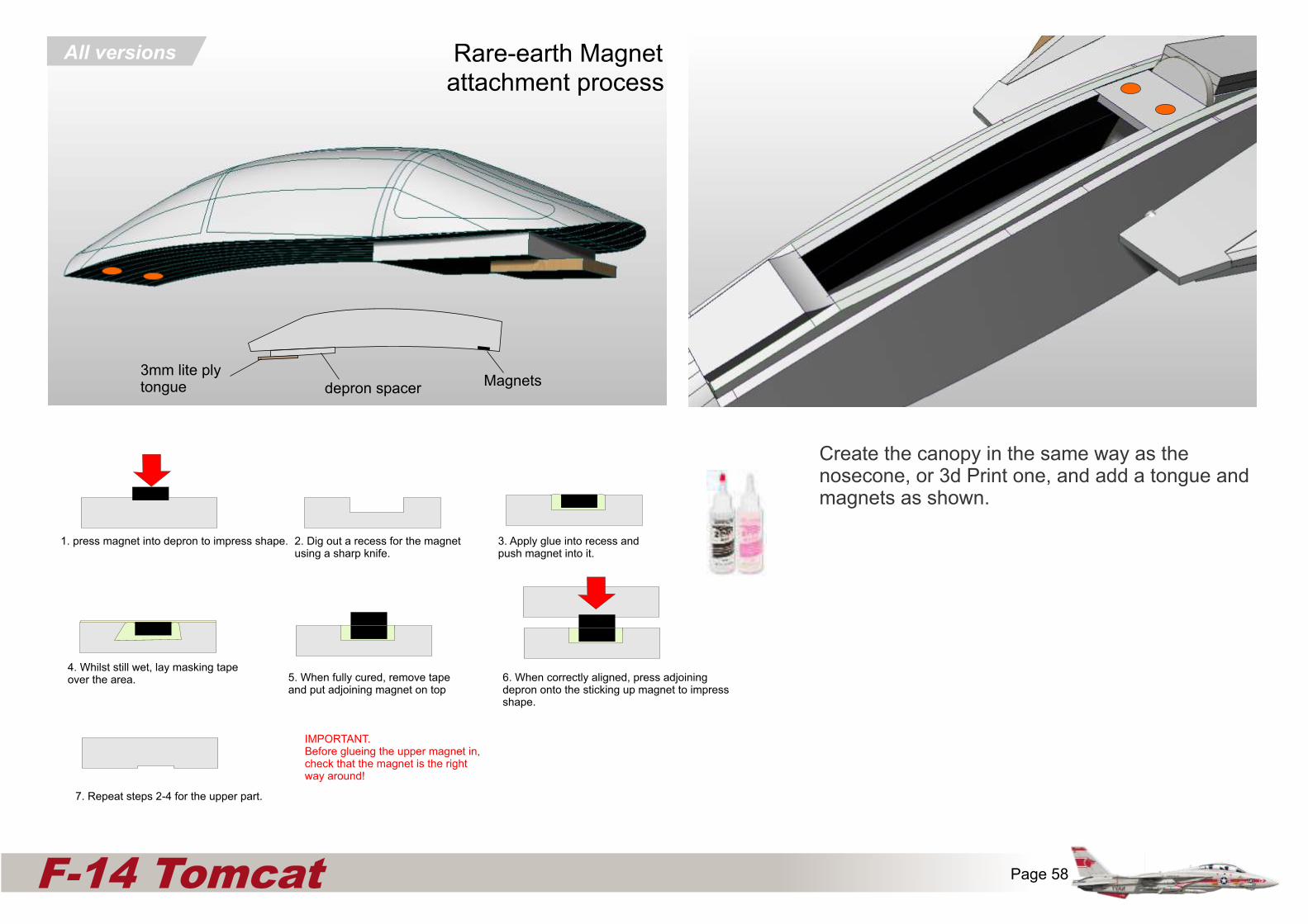
1. press magnet into depron to impress shape. 2. Dig out a recess for the magnetusing a sharp knife.
3. Apply glue into recess andpush magnet into it.
5. When fully cured, remove tapeand put adjoining magnet on top
6. When correctly aligned, press adjoining depron onto the sticking up magnet to impress shape.
7. Repeat steps 2-4 for the upper part.
Rare-earth Magnet
4. Whilst still wet, lay masking tapeover the area.
IMPORTANT.Before glueing the upper magnet in, check that the magnet is the right way around!
depron spacer3mm lite plytongue Magnets
All versions
attachment process
Create the canopy in the same way as the nosecone, or 3d Print one, and add a tongue and magnets as shown.
Page 58F-14 Tomcat
Page 59F-14 Tomcat
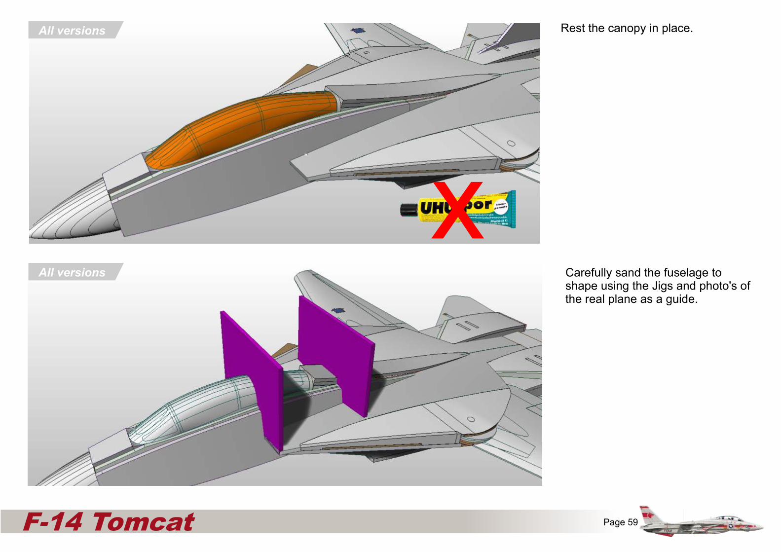
Carefully sand the fuselage to shape using the Jigs and photo's of the real plane as a guide.
All versions
All versions Rest the canopy in place.
x

Page 60F-14 Tomcat
All versions Either make the exhausts using two layers of 3mm depron, or 3d Printed parts and glue onto the exhaust bulkheads.
Carefully sand away the corners of the upper rear fuselage to match the shape of the exhausts bulkheads as indicated in orange.
3DPrinted
Part
3DPrinted
Part(optional)
Page 61F-14 Tomcat
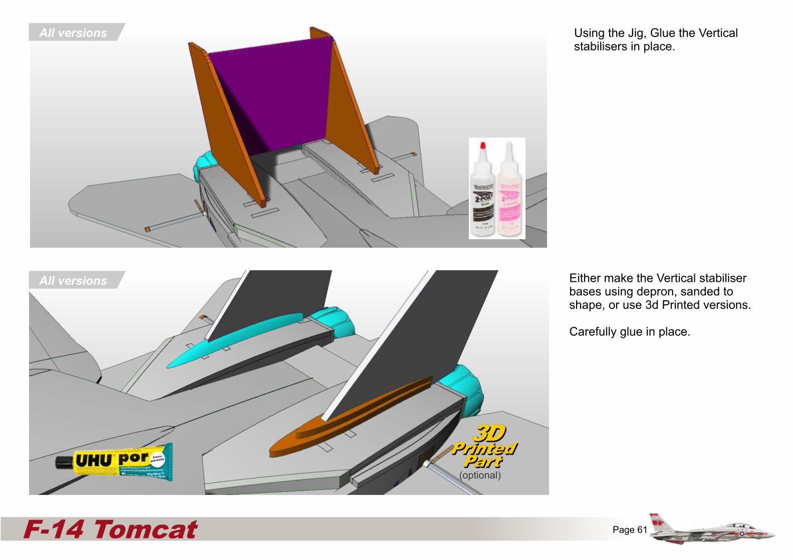
All versions Either make the Vertical stabiliser bases using depron, sanded to shape, or use 3d Printed versions.
Carefully glue in place.
3DPrinted
Part
3DPrinted
Part(optional)
Using the Jig, Glue the Vertical stabilisers in place.
All versions

Page 62F-14 Tomcat
All versions Either create 3mm liteply Ventral fins that attach using magnets, or this 3D printed hinged arrangement using domestic pins as hinges.
Ensure the hinge is not loose, but will fold upon landing.
The Ventral fin is optional and the plane will fly without it.
3DPrinted
Part
3DPrinted
Part(optional)
Using the positions marked on the plans, glue the 2mm balsa or 3mm depron Dorsal Fences to the upper deck.
Alternatively use 3D printed parts.
All versions
3DPrinted
Part
3DPrinted
Part(optional)

Page 63 F-14 Tomcat
All versions
3DPrinted
Part
3DPrinted
Part(optional)
OPTIONAL : Trim back the air intake and glue the 3D printed air intake onto the edge to give a smoother airflow into the air intake and to protect the edges on landings.
All versions
3DPrinted
Part
3DPrinted
Part(optional)
3DPrinted
Part
3DPrinted
Part(optional)
3D print the arrestor hook and cannon, and glue to the aircraft.
On the cannon, rebate the gun nozzle into the depron.

Use photo’s to help shape Your model to representthe real plane
Page 64 F-14 Tomcat