GROUP 8 REFERENCE MATERIAL -...
14
8-1 GROUP 8 REFERENCE MATERIAL CONTENTS BOLTED PANEL FIT AND ADJUSTMENT . . . . . . . . . . . . . . . . . . 8-2 HOOD . . . . . . . . . . . . . . . . . . . . . . . . . . . . . 8-2 DOOR . . . . . . . . . . . . . . . . . . . . . . . . . . . . . 8-3 LIFTGATE . . . . . . . . . . . . . . . . . . . . . . . . . . 8-5 INSTALLATION AND REMOVAL OF ADHESIVE COMPONENTS. . . . . . . . 8-6 GARNISHES AND MOLDINGS . . . . . . . . . 8-6 ADJUSTMENT OF OTHER PARTS . . . . . . . . . . . . . . . . . . . . . . . . 8-7 FRONT WHEEL ALIGNMENT . . . . . . . . . . 8-7 REAR WHEEL ALIGNMENT . . . . . . . . . . . . 8-9 HEADLIGHT AIMING . . . . . . . . . . . . . . . . . 8-10 FOG LIGHT AIMING . . . . . . . . . . . . . . . . . . 8-12 SUPPLEMENTAL RESTRAINT SYSTEM (SRS) - AIR BAG . . . . . . . . . . . . . . . . 8-14
Transcript of GROUP 8 REFERENCE MATERIAL -...

8-1
GROUP 8
REFERENCE MATERIAL
CONTENTS
BOLTED PANEL FIT AND ADJUSTMENT . . . . . . . . . . . . . . . . . . 8-2
HOOD . . . . . . . . . . . . . . . . . . . . . . . . . . . . . 8-2DOOR . . . . . . . . . . . . . . . . . . . . . . . . . . . . . 8-3LIFTGATE. . . . . . . . . . . . . . . . . . . . . . . . . . 8-5
INSTALLATION AND REMOVAL OF ADHESIVE COMPONENTS. . . . . . . . 8-6
GARNISHES AND MOLDINGS . . . . . . . . . 8-6
ADJUSTMENT OF OTHER PARTS . . . . . . . . . . . . . . . . . . . . . . . . 8-7
FRONT WHEEL ALIGNMENT . . . . . . . . . . 8-7REAR WHEEL ALIGNMENT. . . . . . . . . . . . 8-9HEADLIGHT AIMING . . . . . . . . . . . . . . . . . 8-10FOG LIGHT AIMING . . . . . . . . . . . . . . . . . . 8-12
SUPPLEMENTAL RESTRAINT SYSTEM (SRS) - AIR BAG . . . . . . . . . . . . . . . . 8-14
BOLTED PANEL FIT AND ADJUSTMENTREFERENCE MATERIAL8-2
BOLTED PANEL FIT AND ADJUSTMENTHOOD
M4080005000361
ADJUSTMENT OF CLEARANCE AROUND HOODDetach the fender hole cover. Then loosen the hood hinge mounting nuts and bolts as shown, and adjust the hood by moving it until the clearance around it is even.
Hood hinge mounting nut and bolt tightening torque: 12 ± 2 N⋅ m (102 ± 22 in-lb)
NOTE: If the hood hinge mounting bolt washers are welded, grind off the welding according to the procedure below before-hand..1. Remove the hood hinge.2. Use a chisel or grinder to release the hood hinge mounting
bolt washer, which is welded to the hood hinge.3. On completion, paint the affected area with a suitable
touch-up brush to prevent corrosion.4. Install the hood hinge.
ALIGNMENT OF HOOD LATCH AND STRIKERNote the routing of the hood release cable, and then loosen the hood latch mounting bolts. Then align the latch with the striker by moving the hood latch. After alignment, ensure that the hood can be locked and unlocked correctly.
Hood latch mounting bolt tightening torque: 9.0 ± 2.0 N⋅ m (80 ± 17 in-lb)
AC205079AB
HOOD HINGE
AC210131AB
WELD POINT
WASHER
BOLT
HOOD HINGE
NUT
AC405801AB
HOOD LATCH
TSB Revision
BOLTED PANEL FIT AND ADJUSTMENTREFERENCE MATERIAL 8-3
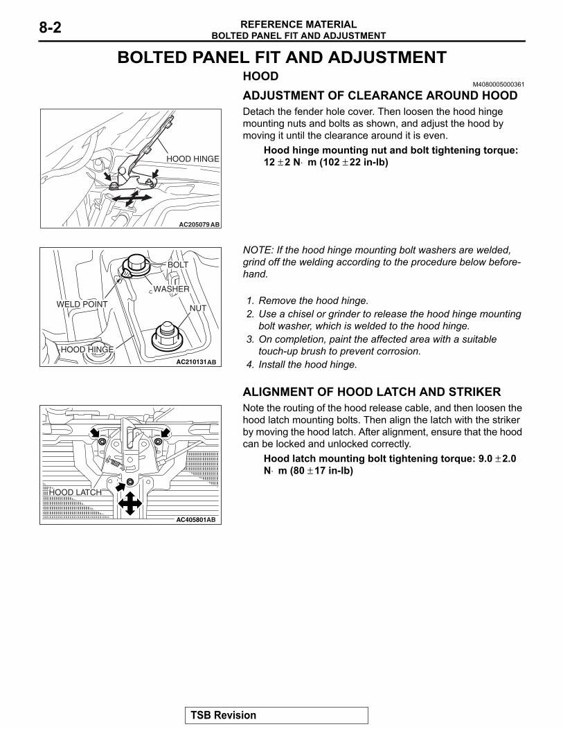
ADJUSTMENT OF HOOD HEIGHTTurn the hood damper until its height is as shown. If the hood height is still not even at left and right sides, turn the hood damper further until the hood height is even. The hood damper height is altered by roughly 3mm (0.1 inch) when turning the hood damper one rotation.NOTE: If a rattling noise is heard caused by the vibration of the hood during driving, adjust the hood damper heights until the hood dampers securely contact the hood.
DOORM4080006000416
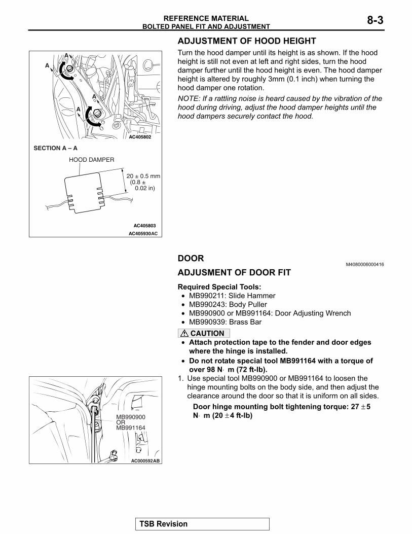
ADJUSMENT OF DOOR FITRequired Special Tools:• MB990211: Slide Hammer• MB990243: Body Puller• MB990900 or MB991164: Door Adjusting Wrench• MB990939: Brass Bar
CAUTION• Attach protection tape to the fender and door edges
where the hinge is installed.• Do not rotate special tool MB991164 with a torque of
over 98 N⋅ m (72 ft-lb).1. Use special tool MB990900 or MB991164 to loosen the
hinge mounting bolts on the body side, and then adjust the clearance around the door so that it is uniform on all sides.
Door hinge mounting bolt tightening torque: 27 ± 5 N⋅ m (20 ± 4 ft-lb)
AC405930
AC405802
AC405803
AC
SECTION A – A
A
A
A
A
HOOD DAMPER
20 ± 0.5 mm (0.8 ± 0.02 in)
AC000592
MB990900ORMB991164
AB
TSB Revision

BOLTED PANEL FIT AND ADJUSTMENTREFERENCE MATERIAL8-4
2. If a door is not flush with its surrounding panels, loosen the door-side door hinge mounting bolts and adjust the door as necessary.
Door hinge mounting bolt tightening torque: 21 ± 4 N⋅ m (16 ± 2 ft-lb)
NOTE: If the door hinge mounting bolt washers are welded, grind off the welding according to the procedure below beforehand.(1) Remove the door hinge. (2) Use a chisel or grinder to release the door hinge
mounting bolt washer, which is welded to the door hinge.(3) On completion, paint the affected area with touch-up
paint to prevent corrosion.(4) Install the door hinge.
3. If the door is stiff to lock and unlock:(1) Adjustment by using the striker (vertically or toward the
inside of the vehicle)Install an temporary bolts instead of the striker mounting bolt, and use special tool MB990939 and a hammer to tap the bolt in the desired direction.
(2) Adjustment by using the striker (toward the outside of the vehicle)Use special tools MB990211 and MB990243 to pull the striker toward the outside of the vehicle.
(3) Adjustment by using shims (forward and rearward)Increase or decrease the number of shims so that the striker engages with the door latch properly.
Door striker mounting bolt tightening torque: 24 ± 3 N⋅ m (18 ± 2 ft-lb)
AC206498
WASHER
BOLT
WASHER
DOOR HINGE ADWELD POINT
WELD POINT
AB301529AB
TEMPORARYBOLTS
STRIKER
MB990939
AC006110
STRIKER
MB990211MB990243
AB
AC006111AB
SHIM
STRIKER
TSB Revision
BOLTED PANEL FIT AND ADJUSTMENTREFERENCE MATERIAL 8-5
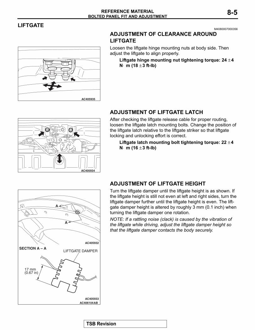
LIFTGATEM4080007000356
ADJUSTMENT OF CLEARANCE AROUND LIFTGATELoosen the liftgate hinge mounting nuts at body side. Then adjust the liftgate to align properly.
Liftgate hinge mounting nut tightening torque: 24 ± 4 N⋅ m (18 ± 3 ft-lb)
ADJUSTMENT OF LIFTGATE LATCHAfter checking the liftgate release cable for proper routing, loosen the liftgate latch mounting bolts. Change the position of the liftgate latch relative to the liftgate striker so that liftgate locking and unlocking effort is correct.
Liftgate latch mounting bolt tightening torque: 22 ± 4 N⋅ m (16 ± 3 ft-lb)
ADJUSTMENT OF LIFTGATE HEIGHTTurn the liftgate damper until the liftgate height is as shown. If the liftgate height is still not even at left and right sides, turn the liftgate damper further until the liftgate height is even. The lift-gate damper height is altered by roughly 3 mm (0.1 inch) when turning the liftgate damper one rotation.NOTE: If a rattling noise (clack) is caused by the vibration of the liftgate while driving, adjust the liftgate damper height so that the liftgate damper contacts the body securely.
AC405935
AC405934
AC405932
AC405933AC406104
A
A
SECTION A – A
17 mm(0.67 in)
LIFTGATE DAMPER
AB
TSB Revision

INSTALLATION AND REMOVAL OF ADHESIVE COMPONENTSREFERENCE MATERIAL8-6
INSTALLATION AND REMOVAL OF ADHESIVE COMPONENTS
GARNISHES AND MOLDINGSM4080020000012
ADHESIVE TAPE POSITION
Required Special Tool:• MB990784: Ornament Remover
AB401322ABAB
ROOF DRIP MOLDING
FRONT PILLAR GARNISH
1.5 ± 0.2 N·m13 ± 2 in-lb
1.5 ± 0.2 N·m13 ± 2 in-lb
1.5 ± 0.2 N·m13 ± 2 in-lb
AB401323AB
ADHESIVE TAPE: DOUBLE-SIDED TAPE A: 10.0 mm ( 0.39 in ) WIDTH AND 1.52 mm ( 0.06 in ) THICKNESS
ROOF DRIP MOLDING
FRONT PILLAR GARNISH
DOUBLE-SIDED TAPE
DOUBLE-SIDED TAPE
TSB Revision
ADJUSTMENT OF OTHER PARTSREFERENCE MATERIAL 8-7
ADJUSTMENT OF OTHER PARTSFRONT WHEEL ALIGNMENT
M4080009000396
Measure wheel alignment with alignment equipment on a level surface. The front suspension, steering system and tires should be serviced to normal condition before measuring wheel align-ment..
TOE-INStandard value: 0 ± 3 mm (0 ± 0.12 inch)
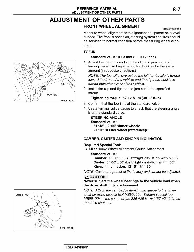
1. Adjust the toe-in by undoing the clip and jam nut, and turning the left and right tie rod turnbuckles by the same amount (in opposite directions).NOTE: The toe will move out as the left turnbuckle is turned toward the front of the vehicle and the right turnbuckle is turned toward the rear of the vehicle.
2. Install the clip and tighten the jam nut to the specified torque.
Tightening torque: 52 ± 2 N⋅ m (38 ± 2 ft-lb)3. Confirm that the toe-in is at the standard value.4. Use a turning radius gauge to check that the steering angle
is at the standard value.STEERING ANGLEStandard value:
31° 48' ± 2° 00' <Inner wheel>27° 06' <Outer wheel (reference)>
.
CAMBER, CASTER AND KINGPIN INCLINATIONRequired Special Tool:• MB991004: Wheel Alignment Gauge Attachment
Standard value:Camber: 0° 00' ± 30' (Left/right deviation within 30') Caster: 3° 00' ± 30' (Left/right deviation within 30') Kingpin inclination: 12° 54' ± 1° 30'
NOTE: Caster are preset at the factory and cannot be adjusted.CAUTION
Never subject the wheel bearings to the vehicle load when the drive shaft nuts are loosened.NOTE: Attach the camber/caster/kingpin gauge to the drive-shaft by using special tool MB991004. Tighten special tool MB991004 to the same torque 226 ± 29 N⋅ m (167 ± 21 ft-lb) as the drive shaft nut.
AC305785AB
JAM NUT
CLIP
AC001079
MB991004
AB
TSB Revision

ADJUSTMENT OF OTHER PARTSREFERENCE MATERIAL8-8
If the camber is outside of the standard value, perform the fol-lowing adjustment procedures.1. Estimate how much additional camber adjustment isrequired. Using the table below, select the camber adjusting bolt, and then replace the knuckle and strut assembly connection bolts (upper bolt, lower bolt) with the selected bolts.
NOTE: "•" indicates upper bolt and lower bolt combination in each selection of CAMBER ADJUSTING VALUE.Bolts are identified in the following table:
NOTE: Set bolt is the bolt installed at factory. "10" embossed on bolt head is head mark.2. Tighten the nuts temporarily, and then pull or push the front
axle to adjust the camber.NOTE: Pulling the upper side of the front axle to the outside of the vehicle will increase the camber. Pushing it to the inside of the vehicle will decrease the camber.
3. Tighten the nuts to 305 ± 25 N⋅ m (225 ± 18 ft-lb).4. Recheck the camber.
BOLT DIAMETER mm (in)
CAMBER ADJUSTING VALUE0° 00' 0° 15' 0° 30' 0° 45' 1° 00' 1° 15'
Upper bolt
16.0 (0.630) • •
14.9 (0.587) • •
14.1 (0.555) •
13.6 (0.535) •
Lower bolt
16.0 (0.630) •
14.9 (0.587) • •
14.1 (0.555) • •
13.6 (0.535) •
DIAMETER A mm (in) NUMBER OF IDENTIFICATION PROJECTION
Set bolt 16.0 (0.630) 0
Adjusting bolt
14.9 (0.587) 1
14.1 (0.555) 2
13.6 (0.535) 3
AC406690
STRUTASSEMBLY
LOWER BOLT
UPPER BOLTKNUCKLE
AB
AC405911AB
A
A
HEAD MARK
IDENTIFICATIONPROJECTION
AC406681
305 ± 25 N·m225 ± 18 ft-lb
AD
TSB Revision

ADJUSTMENT OF OTHER PARTSREFERENCE MATERIAL 8-9
REAR WHEEL ALIGNMENTM4080010000389
Measure wheel alignment with an alignment equipment on level ground.The rear suspension and tires should be serviced to the normal condition prior to wheel alignment measurement..
CAMBERStandard value:
− 0° 50� ± 30� (Left/right deviation within 30�) NOTE: For vehicles with aluminum wheels, attach the camber/caster/kingpin gauge by using a compensator.
.
TOE-INStandard value: 3 ± 3 mm (0.12 ± 0.12 inch)
.
If camber and/or toe-in is not within the standard value, adjust by the following procedures.
CAUTION• When adjusting the camber, tighten the lower arm
assembly and the trailing arm assembly, not the toe control arm.
• After adjusting the camber, be sure to adjust the toe.1. Carry out camber adjustment by turning the assist link bolt.
NOTE: .• LH: Clockwise viewed from the rear → (− ) camber• RH: Clockwise viewed from the rear → (+) camber• If either the camber or toe is adjusted, both should fluctu-
ate. For the relationship between the two, refer to CAM-BER AND TOE REFERENCE TABLE.
AC305848 AB
COMPENSATOR
AC406758AB
TOE CONTROL ARM
ASSIST LINK BOLT
TSB Revision
ADJUSTMENT OF OTHER PARTSREFERENCE MATERIAL8-10
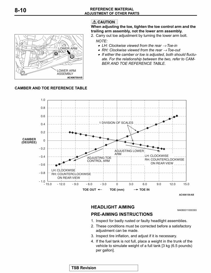
CAUTIONWhen adjusting the toe, tighten the toe control arm and the trailing arm assembly, not the lower arm assembly.2. Carry out toe adjustment by turning the lower arm bolt.
NOTE: .• LH: Clockwise viewed from the rear → Toe-in• RH: Clockwise viewed from the rear → Toe-out• If either the camber or toe is adjusted, both should fluctu-
ate. For the relationship between the two, refer to CAM-BER AND TOE REFERENCE TABLE.
.
CAMBER AND TOE REFERENCE TABLE
HEADLIGHT AIMINGM4080011000393
PRE-AIMING INSTRUCTIONS1. Inspect for badly rusted or faulty headlight assemblies.2. These conditions must be corrected before a satisfactory
adjustment can be made.3. Inspect tire inflation, and adjust if it is necessary.4. If the fuel tank is not full, place a weight in the trunk of the
vehicle to simulate weight of a full tank [3 kg (6.5 pounds) per gallon].
AC406759AB
LOWER ARM ASSEMBLY
LOWER ARM BOLT
AC406159AB
1.0
0.8
0.6
0.4
0.2
0
- 0.2
- 0.4
- 0.6
- 0.8
- 1.0
CAMBER(DEGREE)
1 DIVISION OF SCALES
ADJUSTING TOE CONTROL ARM
LH: CLOCKWISERH: COUNTERCLOCKWISE
ON REAR VIEW
LH: CLOCKWISERH: COUNTERCLOCKWISE
ON REAR VIEW
0 3.0- 3.0- 6.0- 9.0- 12.0- 15.0 6.0 9.0 12.0 15.0
TOE (mm)TOE OUT TOE IN
ADJUSTING LOWER ARM
TSB Revision
ADJUSTMENT OF OTHER PARTSREFERENCE MATERIAL 8-11
5. There should be no other load in the vehicle other than driver or substituted weight of approximately 70 kg (150 pounds) placed in driver's position.
6. Thoroughly clean headlight lenses.7. Place the vehicle on a level floor, perpendicular to a flat
screen 7.62 m (25.0 feet) away from the bulb center-marks on the headlight lens.
8. Rock vehicle sideways to allow vehicle to assume its normal position.
9. Bounce the front suspension through three (3) oscillations by applying the body weight to hood or bumper.
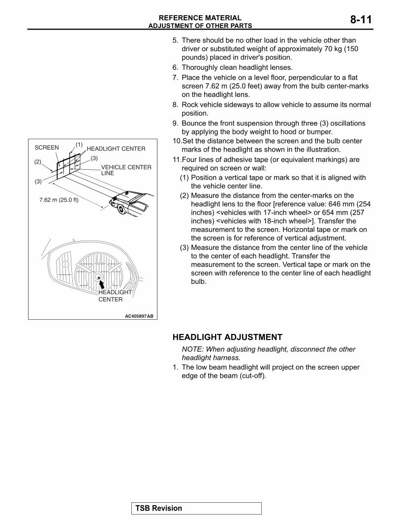
10.Set the distance between the screen and the bulb center marks of the headlight as shown in the illustration.
11.Four lines of adhesive tape (or equivalent markings) are required on screen or wall:(1) Position a vertical tape or mark so that it is aligned with
the vehicle center line.(2) Measure the distance from the center-marks on the
headlight lens to the floor [reference value: 646 mm (254 inches) <vehicles with 17-inch wheel> or 654 mm (257 inches) <vehicles with 18-inch wheel>]. Transfer the measurement to the screen. Horizontal tape or mark on the screen is for reference of vertical adjustment.
(3) Measure the distance from the center line of the vehicle to the center of each headlight. Transfer the measurement to the screen. Vertical tape or mark on the screen with reference to the center line of each headlight bulb.
HEADLIGHT ADJUSTMENTNOTE: When adjusting headlight, disconnect the other headlight harness.
1. The low beam headlight will project on the screen upper edge of the beam (cut-off).
AC405897AB
(1)
(2)
(3)
HEADLIGHT CENTER
VEHICLE CENTER LINE
SCREEN
(3)
7.62 m (25.0 ft)
HEADLIGHTCENTER
TSB Revision
ADJUSTMENT OF OTHER PARTSREFERENCE MATERIAL8-12
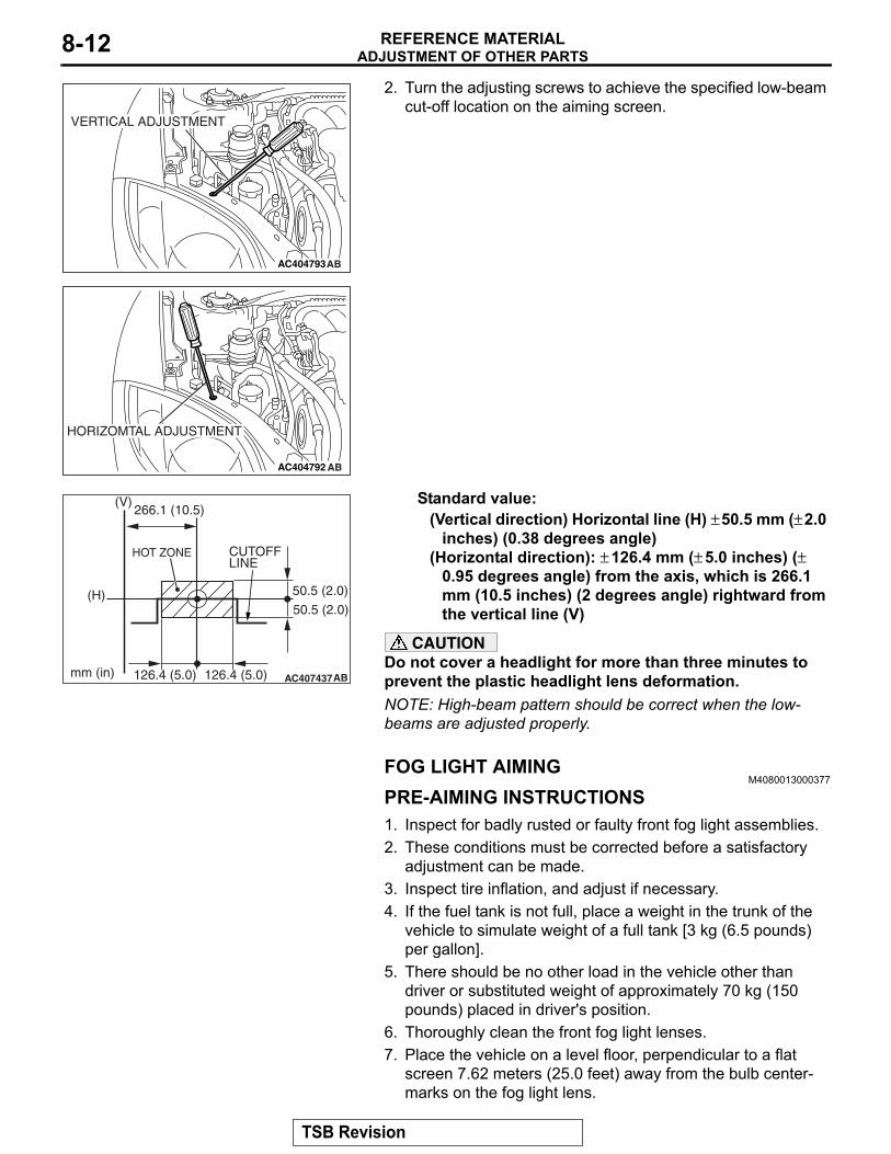
2. Turn the adjusting screws to achieve the specified low-beamcut-off location on the aiming screen.
Standard value:(Vertical direction) Horizontal line (H) ± 50.5 mm (± 2.0
inches) (0.38 degrees angle)(Horizontal direction): ± 126.4 mm (± 5.0 inches) (±
0.95 degrees angle) from the axis, which is 266.1 mm (10.5 inches) (2 degrees angle) rightward from the vertical line (V)
CAUTIONDo not cover a headlight for more than three minutes to prevent the plastic headlight lens deformation.NOTE: High-beam pattern should be correct when the low-beams are adjusted properly.
FOG LIGHT AIMINGM4080013000377
PRE-AIMING INSTRUCTIONS1. Inspect for badly rusted or faulty front fog light assemblies.2. These conditions must be corrected before a satisfactory
adjustment can be made.3. Inspect tire inflation, and adjust if necessary.4. If the fuel tank is not full, place a weight in the trunk of the
vehicle to simulate weight of a full tank [3 kg (6.5 pounds) per gallon].
5. There should be no other load in the vehicle other than driver or substituted weight of approximately 70 kg (150 pounds) placed in driver's position.
6. Thoroughly clean the front fog light lenses.7. Place the vehicle on a level floor, perpendicular to a flat
screen 7.62 meters (25.0 feet) away from the bulb center-marks on the fog light lens.
AC404793AB
VERTICAL ADJUSTMENT
AC404792 AB
HORIZOMTAL ADJUSTMENT
AC407437
(H)
(V)
mm (in) AB
50.5 (2.0)
50.5 (2.0)
HOT ZONE CUTOFF LINE
126.4 (5.0)126.4 (5.0)
266.1 (10.5)
TSB Revision
ADJUSTMENT OF OTHER PARTSREFERENCE MATERIAL 8-13
8. Rock the vehicle sideways to allow the vehicle to assume its normal position.
9. Bounce the front suspension through three (3) oscillations by applying the body weight to the hood or bumper.
10.Measure the center of the front fog lights as shown in the illustration.
11.Four lines of adhesive tape (or equivalent markings) are required on screen or wall:(1) Position a vertical tape or mark so that it is aligned with
the vehicle center line.(2) Measure the distance from the center of the front fog light
lens to the floor. Transfer the measurement to the screen. Horizontal tape or mark on the screen is for reference of vertical adjustment.
(3) Measure the distance from the center line of the vehicle to the center of each front fog light. Transfer the measurement to the screen. Vertical tape or mark on the screen is for reference to the center line of each front fog light.
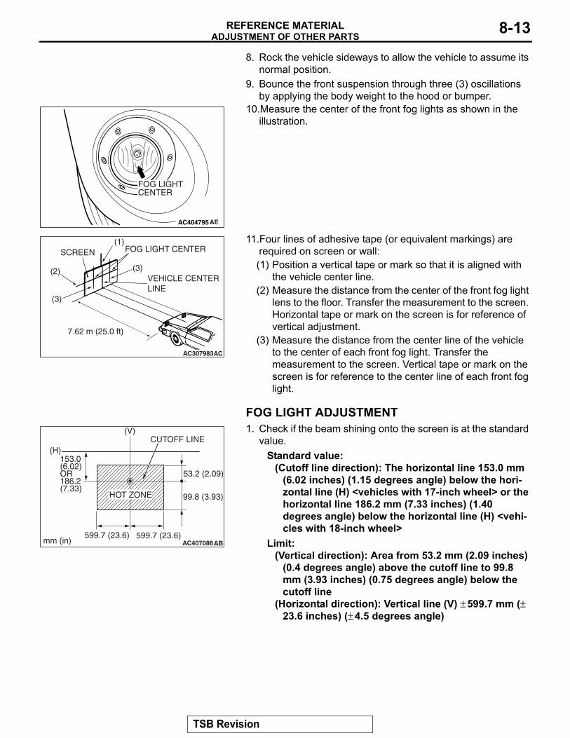
FOG LIGHT ADJUSTMENT1. Check if the beam shining onto the screen is at the standard
value.Standard value:
(Cutoff line direction): The horizontal line 153.0 mm (6.02 inches) (1.15 degrees angle) below the hori-zontal line (H) <vehicles with 17-inch wheel> or the horizontal line 186.2 mm (7.33 inches) (1.40 degrees angle) below the horizontal line (H) <vehi-cles with 18-inch wheel>
Limit:(Vertical direction): Area from 53.2 mm (2.09 inches)
(0.4 degrees angle) above the cutoff line to 99.8 mm (3.93 inches) (0.75 degrees angle) below the cutoff line
(Horizontal direction): Vertical line (V) ± 599.7 mm (± 23.6 inches) (± 4.5 degrees angle)
AC404795AE
FOG LIGHTCENTER
AC307983AC
SCREEN(1)
(2)
(3)
(3)
FOG LIGHT CENTER
VEHICLE CENTER LINE
7.62 m (25.0 ft)
AC407086
CUTOFF LINE(H)
(V)
HOT ZONE
mm (in)
53.2 (2.09)
99.8 (3.93)
153.0 (6.02) OR 186.2 (7.33)
599.7 (23.6) 599.7 (23.6)AB
TSB Revision
SUPPLEMENTAL RESTRAINT SYSTEM (SRS) - AIR BAGREFERENCE MATERIAL8-14
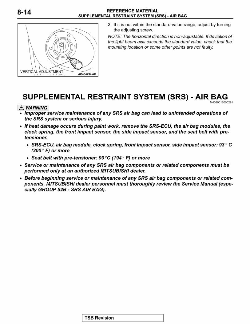
2. If it is not within the standard value range, adjust by turningthe adjusting screw.NOTE: The horizontal direction is non-adjustable. If deviation of the light beam axis exceeds the standard value, check that the mounting location or some other points are not faulty.
SUPPLEMENTAL RESTRAINT SYSTEM (SRS) - AIR BAGM4080016000291
WARNING• Improper service maintenance of any SRS air bag can lead to unintended operations of
the SRS system or serious injury. • If heat damage occurs during paint work, remove the SRS-ECU, the air bag modules, the
clock spring, the front impact sensor, the side impact sensor, and the seat belt with pre-tensioner.• SRS-ECU, air bag module, clock spring, front impact sensor, side impact sensor: 93° C
(200° F) or more• Seat belt with pre-tensioner: 90° C (194° F) or more
• Service or maintenance of any SRS air bag components or related components must be performed only at an authorized MITSUBISHI dealer.
• Before beginning service or maintenance of any SRS air bag components or related com-ponents, MITSUBISHI dealer personnel must thoroughly review the Service Manual (espe-cially GROUP 52B - SRS AIR BAG).
AC404794 ABVERTICAL ADJUSTMENT
TSB Revision