GROUP 11B ENGINE OVERHAUL - Evoscan...FASTENER TIGHTENING SPECIFICATIONS TSB Revision 11B-6 ENGINE...
80
11B-1 GROUP 11B ENGINE OVERHAUL CONTENTS GENERAL SPECIFICATIONS . . . . . . 11B-2 SERVICE SPECIFICATIONS . . . . . . . 11B-2 FASTENER TIGHTENING SPECIFICATIONS . . . . . . . . . . . . . . . 11B-4 SEALANTS AND ADHESIVES . . . . . 11B-7 SPECIAL TOOLS . . . . . . . . . . . . . . . . 11B-8 GENERATOR AND IGNITION SYSTEM . . . . . . . . . . . . . . . . . . . . . . . 11B-10 REMOVAL AND INSTALLATION . . . . . . . . 11B-10 THROTTLE BODY . . . . . . . . . . . . . . . 11B-14 REMOVAL AND INSTALLATION . . . . . . . . 11B-14 INTAKE MANIFOLD AND FUEL SYSTEM . . . . . . . . . . . . . . . . . . . . . . . 11B-16 REMOVAL AND INSTALLATION . . . . . . . . 11B-16 EXHAUST MANIFOLD. . . . . . . . . . . . 11B-20 REMOVAL AND INSTALLATION . . . . . . . . 11B-20 WATER HOSE AND PIPE . . . . . . . . . 11B-24 REMOVAL AND INSTALLATION . . . . . . . . 11B-24 OIL PAN AND TIMING CHAIN CASE. . . . . . . . . . . . . . . . . . . . . . . . . . 11B-27 REMOVAL AND INSTALLATION . . . . . . . . 11B-27 TIMING CHAIN . . . . . . . . . . . . . . . . . . 11B-34 REMOVAL AND INSTALLATION . . . . . . . . 11B-34 INSPECTION. . . . . . . . . . . . . . . . . . . . . . . . 11B-39 CAMSHAFT . . . . . . . . . . . . . . . . . . . . 11B-43 REMOVAL AND INSTALLATION . . . . . . . . 11B-43 INSPECTION. . . . . . . . . . . . . . . . . . . . . . . . 11B-46 CYLINDER HEAD AND VALVES . . . . 11B-49 REMOVAL AND INSTALLATION . . . . . . . . 11B-49 INSPECTION. . . . . . . . . . . . . . . . . . . . . . . . 11B-54 OIL PUMP CHAIN . . . . . . . . . . . . . . . . 11B-58 REMOVAL AND INSTALLATION . . . . . . . . 11B-58 INSPECTION. . . . . . . . . . . . . . . . . . . . . . . . 11B-63 PISTON AND CONNECTING ROD . . 11B-64 REMOVAL AND INSTALLATION . . . . . . . . 11B-64 INSPECTION. . . . . . . . . . . . . . . . . . . . . . . . 11B-72 CRANKSHAFT AND CYLINDER BLOCK . . . . . . . . . . . . . . . . . . . . . . . . 11B-73 REMOVAL AND INSTALLATION . . . . . . . . 11B-73 INSPECTION. . . . . . . . . . . . . . . . . . . . . . . . 11B-78
Transcript of GROUP 11B ENGINE OVERHAUL - Evoscan...FASTENER TIGHTENING SPECIFICATIONS TSB Revision 11B-6 ENGINE...

11B-1
GROUP 11B
ENGINE OVERHAULCONTENTS
GENERAL SPECIFICATIONS. . . . . . 11B-2
SERVICE SPECIFICATIONS. . . . . . . 11B-2
FASTENER TIGHTENING SPECIFICATIONS . . . . . . . . . . . . . . . 11B-4
SEALANTS AND ADHESIVES . . . . . 11B-7
SPECIAL TOOLS. . . . . . . . . . . . . . . . 11B-8
GENERATOR AND IGNITION SYSTEM. . . . . . . . . . . . . . . . . . . . . . . 11B-10
REMOVAL AND INSTALLATION . . . . . . . . 11B-10
THROTTLE BODY . . . . . . . . . . . . . . . 11B-14REMOVAL AND INSTALLATION . . . . . . . . 11B-14
INTAKE MANIFOLD AND FUEL SYSTEM. . . . . . . . . . . . . . . . . . . . . . . 11B-16
REMOVAL AND INSTALLATION . . . . . . . . 11B-16
EXHAUST MANIFOLD. . . . . . . . . . . . 11B-20REMOVAL AND INSTALLATION . . . . . . . . 11B-20
WATER HOSE AND PIPE . . . . . . . . . 11B-24REMOVAL AND INSTALLATION . . . . . . . . 11B-24
OIL PAN AND TIMING CHAIN CASE. . . . . . . . . . . . . . . . . . . . . . . . . . 11B-27
REMOVAL AND INSTALLATION . . . . . . . . 11B-27
TIMING CHAIN . . . . . . . . . . . . . . . . . . 11B-34REMOVAL AND INSTALLATION . . . . . . . . 11B-34INSPECTION. . . . . . . . . . . . . . . . . . . . . . . . 11B-39
CAMSHAFT . . . . . . . . . . . . . . . . . . . . 11B-43REMOVAL AND INSTALLATION . . . . . . . . 11B-43INSPECTION. . . . . . . . . . . . . . . . . . . . . . . . 11B-46
CYLINDER HEAD AND VALVES. . . . 11B-49REMOVAL AND INSTALLATION . . . . . . . . 11B-49INSPECTION. . . . . . . . . . . . . . . . . . . . . . . . 11B-54
OIL PUMP CHAIN. . . . . . . . . . . . . . . . 11B-58REMOVAL AND INSTALLATION . . . . . . . . 11B-58INSPECTION. . . . . . . . . . . . . . . . . . . . . . . . 11B-63
PISTON AND CONNECTING ROD . . 11B-64REMOVAL AND INSTALLATION . . . . . . . . 11B-64INSPECTION. . . . . . . . . . . . . . . . . . . . . . . . 11B-72
CRANKSHAFT AND CYLINDER BLOCK . . . . . . . . . . . . . . . . . . . . . . . . 11B-73
REMOVAL AND INSTALLATION . . . . . . . . 11B-73INSPECTION. . . . . . . . . . . . . . . . . . . . . . . . 11B-78

GENERAL SPECIFICATIONSENGINE OVERHAUL11B-2
GENERAL SPECIFICATIONSM1113000201891
SERVICE SPECIFICATIONSM1113000302169
Descriptions SpecificationsEngine model 4B11Type In line OHV, DOHCNumber of cylinders 4Combustion chamber Pent-roof type
Total displacement cm3 (cu in) 1,998 (121.9)
Cylinder bore mm (in) 86 (3.4)Piston stroke mm (in) 86 (3.4)Compression ratio 9.0Valve timing Intake valve Opens 10° BTDC − 35° BTDC
Closes 62° ABDC − 37° ABDCExhaust valve Open 44° BBDC − 9° BBDC
Close 0° ATDC − 35° ATDCAuto lash adjuster Non-equipped
Item Standard value LimitTiming chainValve clearance mm (in) Intake 0.20 ± 0.03 (0.008 ± 0.001) −
Exhaust 0.30 ± 0.03 (0.012 ± 0.001) −
CamshaftCam height of camshaft mm (in) Intake 44.1 (1.74) 43.6 (1.72)
Exhaust 45.0 (1.77) 44.5 (1.75)Camshaft oil clearance mm (in) 0.035 − 0.072
(0.0014 − 0.0028)−
Cylinder head and valvesDistortion of cylinder head bottom mm (in) Within 0.05 (0.002) 0.2 (0.01)Grinding limit of cylinder head bottom mm (in) − 0.2 (0.01)
Overall height of cylinder head mm (in) 128.5 (5.06) −
Overall length of valve mm (in) Intake 113.18 (4.456) 112.68 (4.436)Exhaust 105.89 (4.169) 105.39 (4.149)
Valve margin mm (in) Intake 1.022 (0.0402) 0.522 (0.0206)Exhaust 1.094 (0.0431) 0.594 (0.0234)
Free height of valve spring mm (in) 51.5 (2.03) 51.0 (2.01)Squareness of valve spring 2° or less 4°
TSB Revision

SERVICE SPECIFICATIONSENGINE OVERHAUL 11B-3
Clearance between valve guide and valve stem mm (in)
Intake 0.020 − 0.047(0.0008 − 0.0019)
0.10 (0.004)
Exhaust 0.030 − 0.057(0.0012 − 0.0022)
0.15 (0.006)
Valve seat contact width mm (in) Intake 1.16 − 1.46 (0.046 − 0.058) −
Exhaust 1.35 − 1.65 (0.053 − 0.065) −
Oversize rework dimensions of valve guide hole mm (in)
0.25 oversize diameter
11.23 − 11.25(0.442 − 0.443)
−
Intake oversize rework dimensions of valve seat hole mm (in)
0.3 oversize diameter
36.22 − 36.24(1.426 − 1.427)
−
Exhaust oversize rework dimensions of valve seat hole mm (in)
0.3 oversize diameter
30.22 − 30.24(1.190 − 1.191)
−
Oil pump chainOil cooler by-pass valve dimension "L" mm (in) 34.5 (1.358) 40.0 (15.75)
Piston and connecting rodClearance between piston ring and ring groove mm (in)
No.1 0.02 − 0.06 (0.001 − 0.002) 0.10 (0.004)No.2 0.02 − 0.06 (0.001 − 0.002) 0.10 (0.004)
Piston ring end gap mm (in) No.1 0.18 − 0.28 (0.007 − 0.011) 0.8 (0.03)No.2 0.28 − 0.43 (0.011 − 0.017) 0.8 (0.03)Oil 0.10 − 0.34 (0.004 − 0.013) 1.0 (0.04)
Clearance of connecting rod big end thrust mm (in) 0.10 − 0.25 (0.004 − 0.010) 0.4 (0.02)Outside diameter of connecting rod bolt mm (in) − 0.10 (0.004)
Connecting rod bearing oil clearance mm (in) 0.038 − 0.069(0.0015 − 0.0027)
0.10 (0.004)
Crankshaft and cylinder blockOut side diameter clearance of crankshaft bearing cap bolt mm (in)
M8 − 0.10 (0.004)
M10 − 0.15 (0.006)
Crankshaft end play mm (in) 0.05 − 0.25 (0.002 − 0.010) 0.4 (0.02)Crankshaft journal oil clearance mm (in)
No.1, 2, 4, 5 0.039 − 0.065(0.0015 − 0.0026)
0.10 (0.004)
No.3 0.051 − 0.077(0.0020 − 0.0030)
0.10 (0.004)
Distortion of cylinder block top surface mm (in) − 0.05 (0.002)
Grinding limit of cylinder block top surface mm (in) − 0.2 (0.01)
Cylinder block cylinder bore mm (in) 86 (3.4) −
Cylindricity of cylinder block mm (in) 0.010 (0.0004) −
Piston-to-cylinder clearanc mm (in) 0.03 − 0.05 (0.001 − 0.002) −
Item Standard value Limit
TSB Revision

FASTENER TIGHTENING SPECIFICATIONSENGINE OVERHAUL11B-4
FASTENER TIGHTENING SPECIFICATIONSM1113023404259
Item SpecificationGenerator and ignition systemIdler pulley bolt 48 ± 7 N⋅ m (36 ± 4 ft-lb)Generator nut 44 ± 10 N⋅ m (32 ± 7 ft-lb)Generator bolt 44 ± 10 N⋅ m (32 ± 7 ft-lb)Power steering pump bracket bolt (M8) 23 ± 2 N⋅ m (17 ± 1 ft-lb)Power steering pump bracket bolt (M10) 44 ± 8 N⋅ m (33 ± 5 ft-lb)Auto tensioner 22 ± 4 N⋅ m (17 ± 2 ft-lb)Crankshaft bolt 250 N⋅ m (184 ft-lb) → 0 → 110 N⋅ m (81 ft-lb) → +60°
Ignition coil bolt 10 ± 2 N⋅ m (89 ± 17 in-lb)Spark plug 18 ± 2 N⋅ m (13 ± 1 ft-lb)
Throttle bodyFuel return pipe bolt 5.5 ± 1.5 N⋅ m (49 ± 13 in-lb)Vacuum pump assembly bolt (M6) 10 ± 2 N⋅ m (89 ± 17 in-lb)Vacuum pump assembly bolt (M8) 24 ± 3 N⋅ m (18 ± 1 ft-lb)Solenoid valve screw 9.5 ± 2.5 N⋅ m (84 ± 22 in-lb)Throttle body bolt 23 ± 6 N⋅ m (17 ± 4 ft-lb)Air temperature sensor 14 ± 1 N⋅ m (128 ± 8 in-lb)Manifold absolute pressure (MAP) sensor screw 5.0 ± 1.0 N⋅ m (48 ± 8 in-lb)
Intake manifold and fuel systemOil dipstick guide bolt 10 ± 2 N⋅ m (89 ± 17 in-lb)Fuel pressure regulator bolt 9.0 ± 3.0 N⋅ m (80 ± 26 in-lb)Fuel rail bolt 12 ± 3 N⋅ m (106 ± 26 ft-lb)Intake manifold stay bolt 23 ± 6 N⋅ m (17 ± 4 ft-lb)Intake manifold nut 20 ± 2 N⋅ m (15 ± 1 ft-lb)Intake manifold assembly bolt washer 20 ± 2 N⋅ m (15 ± 1 ft-lb)Generator bracket bolt 44 ± 8 N⋅ m (33 ± 5 ft-lb)Knock sensor bolt 20 ± 2 N⋅ m (15 ± 1 ft-lb)Engine oil pressure switch 10 ± 2 N⋅ m (89 ± 17 in-lb)
Exhaust manifoldExhaust manifold cover bolt 10 ± 2 N⋅ m (89 ± 17 in-lb)Turbocharger compressor bracket bolt 51 ± 7 N⋅ m (38 ± 4 ft-lb)Turbocharger bracket bolt (Cylinder block side) 51 ± 7 N⋅ m (38 ± 4 ft-lb)Turbocharger bracket bolt (Turbocharger side) 64 ± 5 N⋅ m (47 ± 3 ft-lb)Exhaust fitting bracket bolt (Cylinder block side) 51 ± 7 N⋅ m (38 ± 4 ft-lb)Exhaust fitting bracket bolt (Exhaust fitting side) 64 ± 5 N⋅ m (47 ± 3 ft-lb)Oil return pipe bolt (M6) 9.0 ± 1.0 N⋅ m (80 ± 8 in-lb)Oil return pipe bolt (M8) 25 ± 4 N⋅ m (19 ± 2 ft-lb)Turbocharger and pipe assembly bolt 29 ± 2 N⋅ m (21 ± 1 ft-lb) → +65° ± 5°
TSB Revision

FASTENER TIGHTENING SPECIFICATIONSENGINE OVERHAUL 11B-5
Exhaust manifold nut 49 ± 5 N⋅ m (36 ± 3 ft-lb)Water pipe A bolt (washer bolt) 9.5 ± 1.5 N⋅ m (84 ± 13 in-lb)Water pipe A bolt (Eye bolt) 42 ± 7 N⋅ m (31 ± 5 ft-lb)Water pipe B bolt (Eye bolt) 42 ± 7 N⋅ m (31 ± 5 ft-lb)Oil pipe bolt (Flange bolt) 9.5 ± 2.5 N⋅ m (84 ± 22 in-lb)Oil pipe bolt (Eye bolt M10) 17 ± 2 N⋅ m (13 ± 1 ft-lb)Oil pipe bolt (Eye bolt M12) 31 ± 2 N⋅ m (23 ± 1 ft-lb)Exhaust fitting heat protector A bolt 25 ± 4 N⋅ m (19 ± 2 ft-lb)Exhaust fitting heat protector B bolt 25 ± 4 N⋅ m (19 ± 2 ft-lb)Exhaust fitting bolt, nut 64 ± 5 N⋅ m (47 ± 3 ft-lb)Air outlet fitting bolt 25 ± 4 N⋅ m (19 ± 2 ft-lb)Air inlet fitting bolt 28 ± 1 N⋅ m (21 ± 1 ft-lb)
Water hose and pipeEngine coolant temperature sensor 30 ± 9 N⋅ m (22 ± 6 ft-lb)Water inlet fitting bolt 24 ± 3 N⋅ m (18 ± 1 ft-lb)Water outlet fitting bolt 24 ± 3 N⋅ m (18 ± 1 ft-lb)Thermostat housing bolt 24 ± 3 N⋅ m (18 ± 1 ft-lb)Water pipe nut 24 ± 3 N⋅ m (18 ± 1 ft-lb)Water pump bolt 24 ± 3 N⋅ m (18 ± 1 ft-lb)Engine hanger bolt 28 ± 8 N⋅ m (21 ± 5 ft-lb)Camshaft position sensor 10 ± 2 N⋅ m (89 ± 17 in-lb)Crank position sensor 10 ± 2 N⋅ m (89 ± 17 in-lb)
Oil pan and timing chain casePCV valve 2.5 ± 0.4 N⋅ m (22 ± 3 in-lb)Oil drain plug 39 ± 5 N⋅ m (29 ± 3 ft-lb)Oil filter 14 ± 2 N⋅ m (124 ± 17 in-lb)Cylinder head cover bolt 3.0 ± 1.0 N⋅ m (27 ± 8 in-lb)
→ 5.5 ± 0.5 N⋅ m (49 ± 4 in-lb)Air compressor bracket bolt 23 ± 6 N⋅ m (17 ± 4 ft-lb)Oil pan bolt (M6) 10 ± 2 N⋅ m (89 ± 17 in-lb)Oil pan bolt (M8) 29 ± 2 N⋅ m (21 ± 1 ft-lb)Engine support bracket assembly washer bolt 45 ± 5 N⋅ m (33 ± 3 ft-lb)Timing chain case bolt (M6) 10 ± 2 N⋅ m (89 ± 17 in-lb)Timing chain case bolt (M8 × 10) 13 ± 1 N⋅ m (115 ± 8 in-lb)Timing chain case bolt (M8 × 30) 24 ± 4 N⋅ m (18 ± 2 ft-lb)Engine oil control valve protector bolt 10 ± 2 N⋅ m (89 ± 17 in-lb)
Timing chainChain upper guide bolt 10 ± 2 N⋅ m (89 ± 17 in-lb)Timing chain tensioner bolt 10 ± 2 N⋅ m (89 ± 17 in-lb)Tensioner lever bolt 10 ± 2 N⋅ m (89 ± 17 in-lb)
Item Specification
TSB Revision

FASTENER TIGHTENING SPECIFICATIONSENGINE OVERHAUL11B-6
NEW TIGHTENING METHOD BY USING PLASTIC REGION TIGHTENING BOLT.
Plastic region tightening bolts are used in some parts of the engine. Install these bolts according to the method described in the body of the manual because the tightening method of these bolts are different from the conventional method. The service limit is determined for these bolts. Be sure to strictly follow the service limit described in the body of the manual.• Parts to be used
1. Cylinder head bolt
2. Bearing cap bolt3. Connecting rod cap bolt
• Tightening methodAfter tightening to the specified torque, further tighten 45° and 90° , or 180° (90° + 90° ). Follow the tightening method described in the body of the manual because the tightening method differs from part to part.
Timing chain guide bolt 10 ± 2 N⋅ m (89 ± 17 in-lb)Oil jet bolt 10 ± 2 N⋅ m (89 ± 17 in-lb)V.V.T. intake sprocket bolt 85 ± 5 N⋅ m (63 ± 3 ft-lb)V.V.T. exhaust sprocket bolt 85 ± 5 N⋅ m (63 ± 3 ft-lb)
CamshaftEngine oil control valve (OCV) bolt 10 ± 2 N⋅ m (89 ± 17 in-lb)Front camshaft bearing cap bolt (M8) 17 ± 3 N⋅ m (14 ± 2 ft-lb)
→ 30 ± 2 N⋅ m (22 ± 1 ft-lb)Camshaft bearing cap bolt (M6) 12 ± 1 N⋅ m (107 ± 8 in-lb)
Cylinder head and valvesCylinder head bolt 35 ± 2 N⋅ m (26 ± 1 ft-lb) → +90° → +90°
Oil pump chainFlywheel bolt 40 N⋅ m (30 ft-lb) → 130 N⋅ m (96 ft-lb)Oil seal case bolt 10 ± 2 N⋅ m (89 ± 17 in-lb)Oil pump tensioner lever bolt 10 ± 2 N⋅ m (89 ± 17 in-lb)Oil pump chain guide bolt 10 ± 2 N⋅ m (89 ± 17 in-lb)Oil pump case bolt 26 ± 2 N⋅ m (19 ± 1 ft-lb)Oil pump sprocket bolt 23 ± 2 N⋅ m (17 ± 1 ft-lb)Oil cooler by-pass valve 54 ± 5 N⋅ m (40 ± 3 ft-lb)Ladder frame bolt 26 ± 1 N⋅ m (19 ± 1 ft-lb)Check valve 32 ± 2 N⋅ m (24 ± 1 ft-lb)
Piston and connecting rodConnecting rod cap bolt 5.0 N⋅ m (44 in-lb) → 20 N⋅ m (15 ft-lb) → +90°
Crankshaft and cylinder blockCrankshaft sensing ring bolt 11 ± 1 N⋅ m (98 ± 8 in-lb)Bearing cap bolt (M8) 9.0 ± 2.0 N⋅ m (89 ± 17 in-lb) → +90°
Bearing cap bolt (M10) 37.2 ± 2.0 N⋅ m (28 ± 1 ft-lb) → +90°
Item Specification
TSB Revision

SEALANTS AND ADHESIVESENGINE OVERHAUL 11B-7
SEALANTS AND ADHESIVESM1113000503100
NOTE: The number in square brackets shows the part number..
LIQUID GASKET (FIPG)FIPG is used for some parts in the engine. It is nec-essary to pay attention to an application amount, application procedure and applied surface condition for this gasket to fully achieve its purpose.Too small application amount of FIPG or the dirty surface where the FIPG is applied might cause the FIPG leakage. Too large application amount of FIPG overflows and might clog or narrow the passage of water or oil. It is absolutely essential that the surface where the FIPG is applied must be cleaned and the appropriate amount of FIPG must be evenly applied to prevent the leakage from the connected area.FIPG used for engine parts hardens reacting with moisture in the air, and is usually used for metal flanges..
CAUTIONReapply the FIPG with care to the followings.1. Completely remove the old FIPG including the
residue in gaps of parts.2. Using Mitsubishi genuine parts cleaner
(MZ100387) or equivalent, degrease the FIPG application surface carefully.
3. According to the FIPG application proce-dures, apply it accurately.
.
DISASSEMBLYParts assembled with FIPG can be easily disassem-bled without using a special method. In some cases, however, it is necessary to lightly tap parts with a wooden hammer or similar tool to break sealant between mating surfaces. Or lightly driving a smooth and thin gasket scraper in mating surfaces is useful, but full care must be exercised not to damage mating surfaces. As special tool oil pan FIPG cutter (MD998727) is set, use this tool..
CLEANING OF GASKET SURFACECompletely remove all deposits from the gasket sur-face with a gasket scraper or wire brush. Make sure that the surface to which FIPG is applied is smooth.Completely remove all the old FIPG, which might be remaining in the installation hole, the thread hole or among the components..
APPLICATION PROCEDUREApply FIPG in a determined diameter and continu-ously without break. Completely enclose the periph-ery of mounting holes. FIPG can be wiped off if it is not hardened. Install parts in place while FIPG is still wet. Take care not to allow FIPG to adhere to other locations than necessary locations during installa-tion. Do not pour oil or water on applied locations or do not start the engine until sufficient time (approxi-mately one hour) passes. The application procedure of FIPG may differ depending on areas. Follow the procedure in the body of the manual to apply FIPG.
Item Specified sealantFlywheel bolt Three bond 1324 or equivalentRear oil seal case Three bond 1227D, Three bond 1217G (Mitsubishi Part
No.1000A923), Three bond 1207F (Mitsubishi Part No.1000A992), LOCTITE 5971, LOCTITE 5970, LOCTITE 5900
Ladder frameOil pan
Cylinder head cover (matching area of the cylinder head and the timing chain case assembly)
Three bond 1227D, Three bond 1217G (Mitsubishi Part No.1000A923)
Cylinder head gasket (matching area of the cylinder block and the cylinder head)
Three bond 1217G (Mitsubishi Part No.1000A923) or exact equivalent
Timing chain caseEngine coolant temperature sensor LOCTITE 262, Three bond 1324N or equivalentEngine oil pressure switch Three bond 1215, Three bond 1212D or equivalent
TSB Revision

SPECIAL TOOLSENGINE OVERHAUL11B-8
SPECIAL TOOLSM1113000602494
Tool Tool number and name
Supersession Application
MB991883Flywheel stopper
− Securing of flywheel
MB990767Front hub and flange yoke holder
MB990767-01 Holding the crankshaft pulley
MD998719Pin
MIT308239
MB991398Spark plug wrench
− Removal and installation of spark plug
MB992106O-ring installer
− Installation of O-ring on injector injection nozzle side
MB991614Angle gauge
General service tool Installation of turbocharger and pipe assembly bolt and nut
MB991610Oil filter wrench
General service tool Removal and installation of oil filter
MD998727Oil pan FIPG cutter
MD998727-01 Removal of oil pan
MB991883
B990767
D998719
B992106
MB991614
MB991610
D998727
TSB Revision

SPECIAL TOOLSENGINE OVERHAUL 11B-9
MB991448Bush remover and installer base
MB991448-01 Press fit of front oil seal
MD998735Valve spring compressor
MD998735-01 Compression of valve spring
MB992089Retainer holder C
MB992089-01
MB992085Valve stem seal pliers
− Extraction of valve stem seal
MD998737Valve stem seal installer
MD998737-01 Installation of valve stem seal
MB992236Circlip installer
− Installation of circlip
MD998780Piston pin setting tool
MIT216941
MB991346Top cover wrench
− Holding the oil pump sprocket
Tool Tool number and name
Supersession Application
B991346
TSB Revision

GENERATOR AND IGNITION SYSTEMENGINE OVERHAUL11B-10
GENERATOR AND IGNITION SYSTEMREMOVAL AND INSTALLATION
M1113001002291
Required Special Tools:• MB990767: Front Hub And Flange Yoke Holder• MB991398: Spark Plug Wrench
• MB991883: Flywheel Stopper• MD998719: Pin
AK702234AC
1
2
44 ± 10 N·m32 ± 7 ft-lb
22 ± 4 N·m17 ± 2 ft-lb
18 ± 2 N·m13 ± 1 ft-lb
3
67
8
9
10
48 ± 7 N·m36 ± 4 ft-lb
23 ± 2 N·m17 ± 1 ft-lb
44 ± 8 N·m33 ± 5 ft-lb
5
4
10 ± 2 N·m89 ± 17 in-lb
44 ± 10 N·m32 ± 7 ft-lb48 ± 7 N·m
36 ± 4 ft-lb
250 N·m184 ft-lb
0 in-lb0 N·m
110 N·m81 ft-lb→ → → +60˚
Removal steps 1. Idler pulley2. Idler pulley3. Generator4. Power steering pump bracket
>>C<< 5. Auto tensioner
<<A>> >>B<< 6. Crankshaft pulley center bolt>>B<< 7. Crankshaft pulley washer>>B<< 8. Crankshaft pulley
9. Ignition coil<<B>> >>A<< 10. Spark plug
Removal steps (Continued)
TSB Revision

GENERATOR AND IGNITION SYSTEMENGINE OVERHAUL 11B-11
REMOVAL SERVICE POINT.
<<A>> CRANKSHAFT PULLEY CENTER BOLT REMOVAL1. Use special tool MB991883 to secure the flywheel.
Use the special tool MB990767 and MD998719 to insert the pin into the crankshaft pulley hole and prevent it from rotating.
2. Remove the crankshaft pulley center bolt.
.
<<B>> SPARK PLUG REMOVALUsing special tool MB991398, removal the spark plug.
INSTALLATION SERVICE POINTS.
>>A<< SPARK PLUGS INSTALLATION Using special tool MB991398, tighten the spark plug to the specified torque.
Specified torque: 18 ± 2 N⋅ m (13 ± 1 ft-lb)
AK703300
MB991883
AC
AK703139ACMD998719
MB990767
AK600875
MB991398
AC
Spark plug
AK600875
MB991398
AC
Spark plug
TSB Revision

GENERATOR AND IGNITION SYSTEMENGINE OVERHAUL11B-12
.
>>B<< CRANKSHAFT PULLEY / CRANKSHAFT PULLEY WASHER / CRANKSHAFT PULLEY CENTER BOLT INSTALLATION1. Use special tool MB991883 to secure the flywheel.
Use the special tool MB990767 and MD998719 to insert the pin into the crankshaft pulley hole and prevent it from rotating.
2. Wipe off the dirt on the crankshaft pulley washer and on the thread hole of the crankshaft using a rag.
3. Wipe off the dirt on the crankshaft pulley and the crankshaft sprocket using a rag, and then remove the grease from the portion shown in the illustration.NOTE: Remove grease to prevent the coefficient of friction of the pressing portion from declining due to adhesion of oil.
4. Install the crankshaft pulley.5. Apply an appropriate and minimum amount of engine oil to
the threaded portion of the crankshaft and lower part of the flange.
6. With off the chamfered side on the inside of the washer facing the bolt top, install the washer to the crankshaft pulley center bolt.
7. Tighten the crankshaft pulley center bolt to 250 N⋅ m (164 ft-lb)
8. Loosen the crankshaft pulley center bolt fully.9. Tighten the crankshaft pulley center bolt to 110 N⋅ m (81
ft-lb).
AK703299
MB991883
AC
AK703139ACMD998719
MB990767
AK602911AGEngine front
Crankshaft pulley washer
Crankshaft
Crankshaft pulley
Crankshaft pulley center bolt
Crankshaftsprocket
: Wipe clean with a rag.: Wipe clean with a rag and degrease.: Wipe clean with a rag, degrease and apply a small amount of engine oil.
TSB Revision

GENERATOR AND IGNITION SYSTEMENGINE OVERHAUL 11B-13
10.As shown in the illustration "A," apply the paint mark to the crankshaft pulley on the extended line of the corner adjacent to the one of the crankshaft pulley center bolt corners.CAUTION
• When the tightening angle is smaller than the specified tightening angle, the appropriate tightening capacity cannot be secured.
• When the tightening angle is larger than the specified tightening angle, remove the bolt to start from the beginning again according to the procedure.
11.Tighten the crankshaft pulley center bolt by 60° once more. Make sure the paint mark of crankshaft pulley center bolt is aligned with the paint mark of crankshaft pulley as shown in the illustration "B."
.
>>C<< GENERATOR / POWER STEERING PUMP BRACKET INSTALLATION1. Temporarily tighten power steering pump bracket bolts.
CAUTIONAlways loosen the power steering pump bracket bolt, and temporarily install the generator. Then tighten each bolt.2. Loosen the power steering pump bracket bolts and make
the power steering pump bracket unfixed.3. Temporarily install the generator with the generator bolts.4. Tighten them to the specified torque according to the order
as illustrated.Specified torque
Power steering pump bracket:M8 23 ± 2 N⋅ m (17 ± 1 ft-lb)M10 44 ± 8 N⋅ m (33 ± 5 ft-lb)
Generator: 44 ± 10 N⋅ m (32 ± 7 ft-lb)
AK703140AC
A B60˚
Paint mark
Cankshaft pulleycenter bolt
AK503383AJ
Generator
1
2
3
4
5
Power steering pump bracket
TSB Revision
THROTTLE BODYENGINE OVERHAUL11B-14
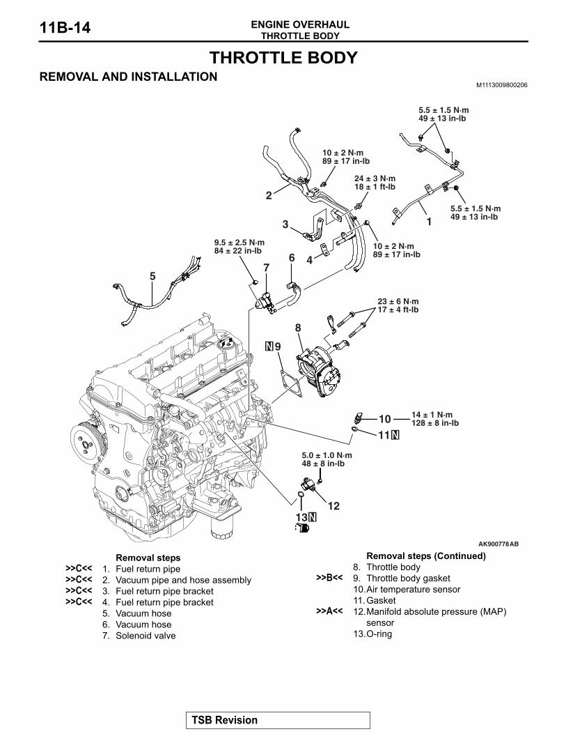
THROTTLE BODYREMOVAL AND INSTALLATION
M1113009800206
AK900778AB
7
2
5
10 ± 2 N·m89 ± 17 in-lb
8
9
24 ± 3 N·m18 ± 1 ft-lb
9.5 ± 2.5 N·m84 ± 22 in-lb
23 ± 6 N·m17 ± 4 ft-lb
6
11
14 ± 1 N·m128 ± 8 in-lb10
12
5.0 ± 1.0 N·m48 ± 8 in-lb
13
4
3
10 ± 2 N·m89 ± 17 in-lb
5.5 ± 1.5 N·m49 ± 13 in-lb
5.5 ± 1.5 N·m49 ± 13 in-lb1
Removal steps >>C<< 1. Fuel return pipe>>C<< 2. Vacuum pipe and hose assembly>>C<< 3. Fuel return pipe bracket>>C<< 4. Fuel return pipe bracket
5. Vacuum hose6. Vacuum hose7. Solenoid valve
8. Throttle body>>B<< 9. Throttle body gasket
10.Air temperature sensor11.Gasket
>>A<< 12.Manifold absolute pressure (MAP) sensor
13.O-ring
Removal steps (Continued)
TSB Revision

THROTTLE BODYENGINE OVERHAUL 11B-15
INSTALLATION SERVICE POINTS.
>>A<< MANIFOLD ABSOLUTE PRESSURE (MAP) SENSOR INSTALLATION
CAUTION• Install the manifold absolute pressure (MAP) sensor,
taking care not to give a shock to it.• Do not use a manifold absolute pressure (MAP) sensor
that has been dropped..
>>B<< THROTTLE BODY GASKET INSTALLATION Install a new gasket so that the tab is positioned as shown in the illustration.
.
>>C<< FUEL RETURN PIPE / VACUUM PIPE AND HOSE ASSEMBLY / FUEL RETURN PIPE BRACKET INSTALLATION1. Tighten the fuel return pipe bracket together with the
vacuum pipe and hose. Install it to the cylinder head and intake manifold. Tighten it to the specified torque.
Specified torque M6: 10 ± 2 N⋅ m (89 ± 17 in-lb) M8: 24 ± 3 N⋅ m (18 ± 1 ft-lb)
2. Insert the clip of the fuel return pipe to the weld bolt of the fuel return pipe bracket.
3. Temporarily tighten the fuel return pipe at the 5 bolt.4. Tighten the fuel return pipe to the tightening torque in the
order 1 to 5 shown in the illustration.Specified torque: 5.5 ± 1.5 N⋅ m (49 ± 13 in-lb)
AK702206AC
Tab
AK900783AB
2 1
3
4
5
TSB Revision

INTAKE MANIFOLD AND FUEL SYSTEMENGINE OVERHAUL11B-16
INTAKE MANIFOLD AND FUEL SYSTEMREMOVAL AND INSTALLATION
M1113032500995
Required Special Tool:• MB992106: O-ring Installer
AK900777
3
7
1
2
18
19
2044 ± 8 N·m33 ± 5 ft-lb
21
20 ± 2 N·m15 ± 1 ft-lb
22
14
15
17
23 ± 6 N·m17 ± 4 ft-lb
12 ± 3 N·m106 ± 26 in-lb
56
8
16
9.0 ± 3.0 N·m80 ± 26 in-lb
1011
12
13
9
AB
4
10 ± 2 N·m89 ± 17 in-lb
10 ± 2 N·m89 ± 17 in-lb
23 ± 6 N·m17 ± 4 ft-lb
20 ± 2 N·m15 ± 1 ft-lb
20 ± 2 N·m15 ± 1 ft-lb
Removal steps 1. Oil dipstick rod2. O-ring3. Fuel hose4. Vacuum hose
>>G<< 5. Fuel pressure regulator6. O-ring
>>F<< 7. Fuel rail assembly8. Insulator
>>E<< 9. Injection support>>E<< 10.O-ring>>E<< 11. Injector
>>D<< 12.O-ring13.Fuel rail
>>C<< 14.Intake manifold stay front>>C<< 15.Intake manifold stay rear
16.Intake manifold17.Intake manifold gasket18.Oil dipstick guide19.O-ring20.Generator bracket
>>B<< 21.Knock sensor>>A<< 22.Engine oil pressure switch
Removal steps (Continued)
TSB Revision

INTAKE MANIFOLD AND FUEL SYSTEMENGINE OVERHAUL 11B-17
INSTALLATION SERVICE POINTS.
>>A<< ENGINE OIL PRESSURE SWITCH INSTAL-LATION
CAUTION• Do not allow sealant to squeeze out to the screw tip.• Do not exceed the specified torque.
1. Completely remove sealant adhering to the engine oil pressure switch and cylinder block threaded holes.
2. Apply sealant (Three bond 1215, Three bond 1212D or equivalent) of 5 mm (0.2 inch) to the threaded portion of the engine oil pressure switch shown in the illustration.
3. Tighten the engine oil pressure switch to the cylinder block to the specified torque.
Specified torque: 10 ± 2 N⋅ m (89 ± 17 in-lb).
>>B<< KNOCK SENSOR INSTALLATIONAlign the knock sensor connector with the position shown in the illustration, and then tighten it to the specified torque.
Specified torque: 20 ± 2 N⋅ m (15 ± 1 ft-lb)
.
>>C<< INTAKE MANIFOLD STAY INSTALLATIONMake sure that the intake manifold stay is in intimate contact with the intake manifold and cylinder block boss before tighten-ing it to the specified torque.
Specified torque: 23 ± 6 N⋅ m (17 ± 4 ft-lb)
.
AK502866AD
AK702207AC
135˚
Knock sensor
AK702208AC
Intake manifoldstay front
Intake manifoldstay rear
TSB Revision

INTAKE MANIFOLD AND FUEL SYSTEMENGINE OVERHAUL11B-18
>>D<< O-RING INSTALLATION When inserting an O-ring into the injector on the injection noz-zle side, use special tool MB992106 to gradually expand the O-ring, and fit it in place.
.
>>E<< INJECTOR / O-RING / INJECTOR SUPPORT INSTALLATION
CAUTIONDo not allow gasoline to enter the fuel rail.1. Apply gasoline to the O-ring of the injector.2. Insert the injector into the fuel rail while rotating the injector
from side to side, taking care not to damage the O-ring.3. Check that the injector rotates smoothly. If it does not rotate
smoothly, the O-ring may be caught. Remove the injector and check the O-ring for damage. Then, insert it again into the fuel rail and check.
4. Make sure that the protrusion of the injector is at the center as shown in the illustration.
5. Securely assemble the injector to the injector groove and fuel rail collar.
.
AK502784AD
MB992106
AK502744
AK800066
TSB Revision

INTAKE MANIFOLD AND FUEL SYSTEMENGINE OVERHAUL 11B-19
>>F<< FUEL RAIL ASSEMBLY INSTALLATION1. Apply gasoline to the pressure side O-ring of the injector.2. Tighten the fuel rail assembly to the intake manifold to the
specified torque.Specified torque: 12 ± 3 N⋅ m (106 ± 26 in-lb)
.
>>G<< FUEL PRESSURE REGULATOR INSTALLATION1. Apply gasoline to the new O-ring.
CAUTIONDo not allow gasoline to enter the fuel rail.2. Insert the fuel pressure regulator into the fuel rail while
rotating the injector from side to side, taking care not to damage the O-ring.
3. Check that the fuel pressure regulator rotates smoothly. If it does not rotate smoothly, the O-ring may be caught. Remove the fuel pressure regulator and check the O-ring for damage. Then, insert it again into the fuel rail and check.
TSB Revision

EXHAUST MANIFOLDENGINE OVERHAUL11B-20
EXHAUST MANIFOLDREMOVAL AND INSTALLATION M1113004901900
Required Special Tool:• MB991614: Angle Sensor
AK900128
1
9
810
15
11
13
4
5
3 6
2021
17 ± 2 N·m13 ± 1 ft-lb
14 16
17
18
19
12
22
9.5 ± 2.5 N·m84 ± 22 in-lb
51 ± 7 N·m38 ± 4 ft-lb
51 ± 7 N·m38 ± 4 ft-lb
9.0 ± 1.0 N·m80 ± 8 in-lb
9.0 ± 1.0 N·m80 ± 8 in-lb
42 ± 7 N·m31 ± 5 ft-lb
9.5 ± 1.5 N·m84 ± 13 in-lb
28 ± 1 N·m21 ± 1 ft-lb
49 ± 5 N·m36 ± 3 ft-lb
29 ± 2 N·m21 ± 1 ft-lb
AC
64 ± 5 N·m47 ± 3 ft-lb
25 ± 4 N·m19 ± 2 ft-lb
64 ± 5 N·m47 ± 3 ft-lb
2
7
64 ± 5 N·m47 ± 3 ft-lb
10 ± 2 N·m89 ± 17 in-lb
25 ± 4 N·m19 ± 2 ft-lb
64 ± 5 N·m47 ± 3 ft-lb
25 ± 4 N·m19 ± 2 ft-lb
25 ± 4 N·m19 ± 2 ft-lb
51 ± 7 N·m38 ± 4 ft-lb
25 ± 4 N·m19 ± 2 ft-lb
42 ± 7 N·m31 ± 5 ft-lb
31 ± 2 N·m23 ± 1 ft-lb
→ +65˚ ± 5˚
Removal steps 1. Exhaust manifold cover
>>H<< 2. Turbocharger compressor bracket>>G<< 3. Exhaust fitting bracket
4. Oil return pipe>>F<< 5. Oil return pipe gasket>>E<< 6. Turbocharger bracket>>D<< 7. Turbocharger and pipe assembly
8. Turbocharger gasket9. Exhaust manifold10. Exhaust manifold gasket11. Water pipe A
>>C<< 12. Water pipe B13. Oil pipe14. Exhaust fitting heat protector A15. Exhaust fitting heat protector B16. Exhaust fitting17. Exhaust fitting gasket18. Air outlet fitting
>>B<< 19. Air outlet fitting gasket20. Air inlet fitting
>>A<< 21. Air inlet fitting gasket22. Turbocharger
Removal steps (Continued)
TSB Revision

EXHAUST MANIFOLDENGINE OVERHAUL 11B-21
INSTALLATION SERVICE POINTS.
>>A<< AIR INLET FITTING GASKET INSTALLA-TIONInstall a new gasket so that the tab is positioned as shown in the illustration.
.
>>B<< AIR OUTLET FITTING GASKET INSTALLATIONInstall a new gasket so that the tab is positioned as shown in the illustration.
.
>>C<< WATER PIPE B INSTALLATIONMake sure the bracket of water pipe "B" is inserted into the hole of turbocharger as shown in the illustration, and then install the eye bolt.NOTE: Be sure to install the gasket.
.
AK703235AC
Tab
Tab
AK703234AC
Tab
AK703725AC
Bracket
Hole
Bracket
Water pipe B
Turbocharger
Hole
TSB Revision

EXHAUST MANIFOLDENGINE OVERHAUL11B-22
>>D<< TURBOCHARGER AND PIPE ASSEMBLY INSTALLATION1. Make sure the identification hole is properly in position as
shown in the illustration, and then install the coned disc spring in the appropriate installation direction.
2. Tighten the bolts and nuts to the specified torque.Specified torque: 29 ± 2 N⋅ m (21 ± 1 ft-lb)
3. Use special tool MB991614 to tighten bolts and nuts 65° ± 5° .CAUTION
• When the tightening angle is smaller than the specified tightening angle, the appropriate tightening capacity cannot be secured.
• When the tightening angle is larger than the specified tightening angle, remove the bolt and nut to start from the beginning again according to the procedure.
.
>>E<< TURBOCHARGER BRACKET INSTALLATION1. After temporarily tightening the turbocharger bracket with
the installation bolts, check the exhaust manifold fastens securely to the cylinder block and the turbocharger.
2. Tighten the cylinder block side bolt to the specified tightening torque.
Specified torque: 51 ± 7 N⋅ m (38 ± 4 ft-lb)3. Tighten the turbocharger side bolt to the specified tightening
torque.Specified torque: 64 ± 5 N⋅ m (47 ± 3 ft-lb)
.
AK704038AB
Identificationhole
Identification holeTurbocharger side
Bolt and nut side
AK703730
65˚ ± 5˚
ACMB991614
AK900166AC
Cylinderblock
Turbocharger
Turbochargerbracket
A
DropDrop
A
A-A
Washer
TSB Revision

EXHAUST MANIFOLDENGINE OVERHAUL 11B-23
>>F<< OIL RETURN PIPE GASKET INSTALLATIONInstall a new gasket so that the tab is positioned as shown in the illustration.
.
>>G<< EXHAUST FITTING BRACKET INSTALLATION1. After temporarily tightening the exhaust fitting bracket with
the installation bolts, check the exhaust manifold fastens securely to the cylinder block and the exhaust fitting.
2. Tighten the cylinder block side bolt to the specified tightening torque.
Specified torque: 51 ± 7 N⋅ m (38 ± 4 ft-lb)3. Tighten the exhaust fitting bracket side bolt to the specified
tightening torque.Specified torque: 64 ± 5 N⋅ m (47 ± 3 ft-lb)
.
>>H<< TURBOCHARGER COMPRESSOR BRACKET INSTALLATION1. After temporarily tightening the turbocharger compressor
bracket with the installation bolts, check the exhaust manifold fastens securely to the cylinder block and the turbocharger.
2. Tighten the cylinder block side bolt to the specified tightening torque.
Specified torque: 51 ± 7 N⋅ m (38 ± 4 ft-lb)3. Tighten the turbocharger side bolt to the specified tightening
torque.Specified torque: 51 ± 7 N⋅ m (38 ± 4 ft-lb)
AK703233AC
Tab
AK900167ACCylinder block
Exhaust fitting
Exhaust fittingbracket
DropDropA-A
Washer
AA
AA
AK703144AC
Turbochargercompressor bracket
Cylinder block
TSB Revision

WATER HOSE AND PIPEENGINE OVERHAUL11B-24
WATER HOSE AND PIPEREMOVAL AND INSTALLATION
M1113032900249
AK702230
15 16
1
17
2021
10 ± 2 N·m89 ± 17 in-lb
1819
8
9
6
30 ± 9 N·m22 ± 6 ft-lb
75
1011
12
13
AC
28 ± 8 N·m21 ± 5 ft-lb
24 ± 3 N·m18 ± 1 ft-lb
10 ± 2 N·m89 ± 17 in-lb
2
4
14
3
2223
10 ± 2 N·m89 ± 17 in-lb
24 ± 3 N·m18 ± 1 ft-lb
24 ± 3 N·m18 ± 1 ft-lb
24 ± 3 N·m18 ± 1 ft-lb
24 ± 3 N·m18 ± 1 ft-lb
Removal steps 1. Water hose2. Water hose3. Water hose4. Water hose
>>E<< 5. Engine coolant temperature sensor6. Water outlet fitting
>>D<< 7. Water outlet fitting gasket8. Water inlet fitting
>>C<< 9. Thermostat>>B<< 10. Thermostat housing
11. Thermostat housing gasket>>B<< 12. Water pipe assembly
>>B<< 13. Water pipe gasket14. O-ring15. Water pump assembly16. Water pump gasket17. Engine hanger18. Intake camshaft position sensor19. O-ring20. Exhaust camshaft position sensor21. O-ring
>>A<< 22. Crankshaft position sensor23. O-ring
Removal steps (Continued)
TSB Revision

WATER HOSE AND PIPEENGINE OVERHAUL 11B-25
INSTALLATION SERVICE POINTS.
>>A<< CRANKSHAFT POSITION SENSOR INSTALLATION
CAUTION• Do not apply a force such as torsion or twist to the
O-ring during assembly of the sensor.• Assemble the sensor, taking care not to give a shock to
it.• Do not use a sensor that has been dropped.
Tighten the crankshaft position sensor to the specified torque.Specified torque: 10 ± 2 N⋅ m (89 ± 17 in-lb)
.
>>B<< THERMOSTAT HOUSING / WATER PIPE ASSEMBLY / WATER PIPE GASKET INSTALLATION1. Assemble the thermostat housing and water pipe2. Install the thermostat housing gasket.3. Install a new water pipe gasket so that the tab is positioned
as shown in the illustration.4. Temporarily tighten them to the cylinder head and water
pump. Then tighten them to the specified torque.Specified torque: 24 ± 3 N⋅ m (18 ± 1 ft-lb)
.
>>C<< THERMOSTAT INSTALLATION Install the thermostat with the jiggle valve facing almost straight upwards.
.
AK703291AC
Tab
AK703293AC
Jiggle valve
TSB Revision
WATER HOSE AND PIPEENGINE OVERHAUL11B-26
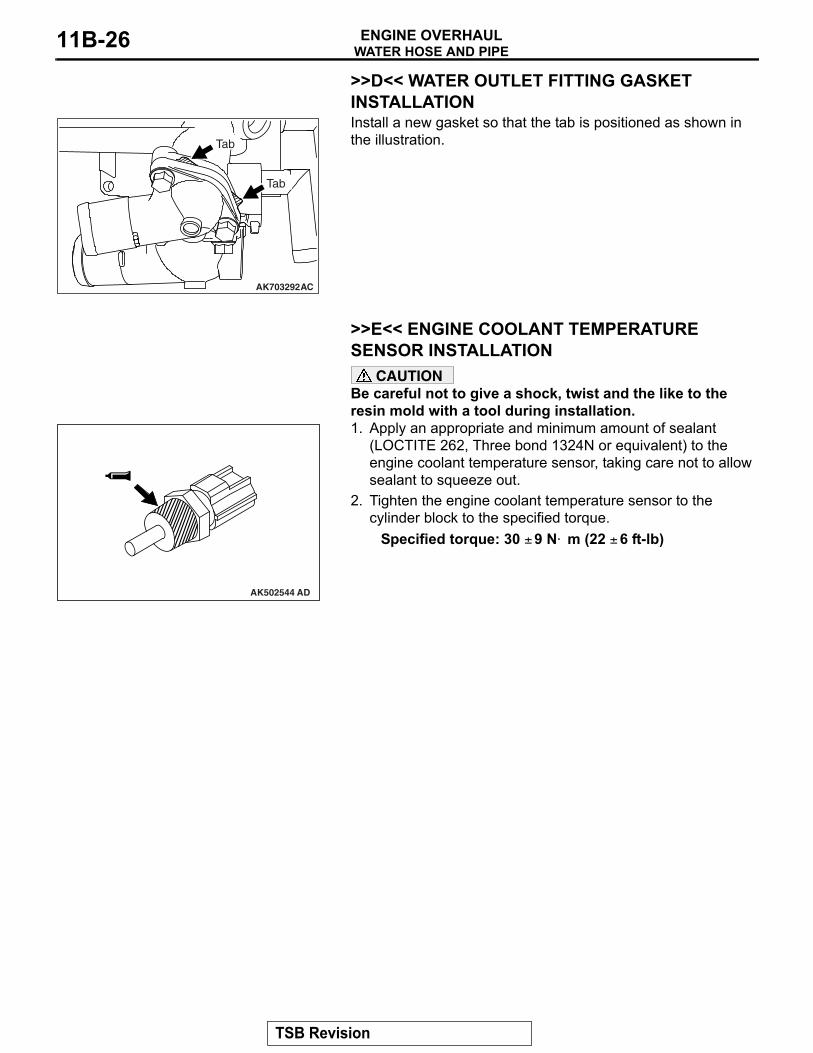
>>D<< WATER OUTLET FITTING GASKET INSTALLATIONInstall a new gasket so that the tab is positioned as shown in the illustration.
.
>>E<< ENGINE COOLANT TEMPERATURE SENSOR INSTALLATION
CAUTIONBe careful not to give a shock, twist and the like to the resin mold with a tool during installation.1. Apply an appropriate and minimum amount of sealant
(LOCTITE 262, Three bond 1324N or equivalent) to the engine coolant temperature sensor, taking care not to allow sealant to squeeze out.
2. Tighten the engine coolant temperature sensor to the cylinder block to the specified torque.
Specified torque: 30 ± 9 N⋅ m (22 ± 6 ft-lb)
AK703292AC
Tab
Tab
AK502544 AD
TSB Revision
OIL PAN AND TIMING CHAIN CASEENGINE OVERHAUL 11B-27
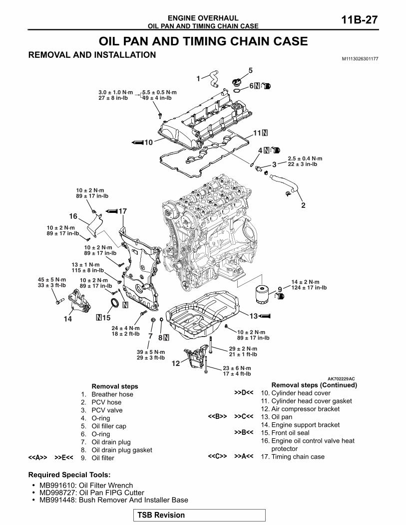
OIL PAN AND TIMING CHAIN CASEREMOVAL AND INSTALLATION M1113026301177
Required Special Tools:• MB991610: Oil Filter Wrench• MD998727: Oil Pan FIPG Cutter• MB991448: Bush Remover And Installer Base
AK702229AC
1
2
3
4
5
6
2.5 ± 0.4 N·m22 ± 3 in-lb
1110
5.5 ± 0.5 N·m49 ± 4 in-lb
3.0 ± 1.0 N·m27 ± 8 in-lb
45 ± 5 N·m33 ± 3 ft-lb
1524 ± 4 N·m18 ± 2 ft-lb
87
39 ± 5 N·m29 ± 3 ft-lb
12
914 ± 2 N·m124 ± 17 in-lb
13
13 ± 1 N·m115 ± 8 in-lb
17
14
29 ± 2 N·m21 ± 1 ft-lb
23 ± 6 N·m17 ± 4 ft-lb
1610 ± 2 N·m89 ± 17 in-lb
10 ± 2 N·m89 ± 17 in-lb
10 ± 2 N·m89 ± 17 in-lb
10 ± 2 N·m89 ± 17 in-lb
10 ± 2 N·m89 ± 17 in-lb
→
Removal steps 1. Breather hose2. PCV hose3. PCV valve4. O-ring5. Oil filler cap6. O-ring7. Oil drain plug8. Oil drain plug gasket
<<A>> >>E<< 9. Oil filter
>>D<< 10. Cylinder head cover11. Cylinder head cover gasket12. Air compressor bracket
<<B>> >>C<< 13. Oil pan14. Engine support bracket
>>B<< 15. Front oil seal16. Engine oil control valve heat
protector<<C>> >>A<< 17. Timing chain case
Removal steps (Continued)
TSB Revision

OIL PAN AND TIMING CHAIN CASEENGINE OVERHAUL11B-28
REMOVAL SERVICE POINTS.
<<A>> OIL FILTER REMOVALUse special tool MB991610 to remove the oil filter.
.
<<B>> OIL PAN REMOVAL1. Remove oil pan tightening bolts.
CAUTIONLightly tap the oil pan FIPG cutter to drive in, taking care not to damage the ladder frame and oil pan sealed area.2. Lightly tap special tool MD998727 to drive in the illustrated
groove of the oil pan and ladder frame.
3. Lightly tap and slide special tool MD998727 to remove the oil pan.
.
AK703592AC
MB991610
AK702205AC
Groove
Groove
AK502732AD
MD998727
TSB Revision

OIL PAN AND TIMING CHAIN CASEENGINE OVERHAUL 11B-29
<<C>> TIMING CHAIN CASE REMOVALIf the timing chain case is difficult to remove, insert a hammer handle as shown in the illustration and lightly pry it.
INSTALLATION SERVICE POINTS.
>>A<< TIMING CHAIN CASE INSTALLATIONCAUTION
• Completely remove all the old liquid gasket, which might be remaining in the installation hole, the O-ring groove or among the components such as the cylinder head gasket.
• Sufficiently check that there is no residual oil on the place where degreasing is performed. If fingerprints are left, do not touch it with bare hands after the degreas-ing, since the oils from your fingers will harm the seal ability.
1. Completely remove liquid gasket adhering to the timing chain case, cylinder block and cylinder head.
2. Degrease the surface where the liquid gasket is applied and the contact surface between the cylinder block and the cylinder head.
AK502907
Hammer
AD
AK703733
D
AA
B-B view
A-A view D
AD
B A A
G C
C-C view
C
BB
7.5 ± 0.5 mm(0.30 ± 0.02 in)
3.0 ± 0.5 mm(0.12 ± 0.02 in)
2.5 mm(0.10 in)
1.0 ± 0.5 mm(0.04 ± 0.02 in)
Ø2.5 ± 0.5 mm(0.10 ± 0.02 in)
4.5 ± 0.5 mm(0.18 ± 0.02 in)
3.0 ± 0.5 mm(0.12 ± 0.02 in)
Ø2.5 ± 0.5 mm(0.10 ± 0.02 in)
Ø2.5 ± 0.5 mm(0.10 ± 0.02 in)
Ø4.5 ± 0.5 mm(0.18 ± 0.02 in)
Ø2.5 ± 0.5 mm(0.10 ± 0.02 in)
TSB Revision

OIL PAN AND TIMING CHAIN CASEENGINE OVERHAUL11B-30
CAUTIONInstall the timing chain case within three minutes after applying liquid gasket.3. Apply liquid gasket (Three bond 1217G [Mitsubishi Part
No.1000A923] or equivalent) of 2.5 ± 0.5 mm (0.10 ± 0.02 inch) in thickness to the timing chain case. For illustrated A locations, however, apply liquid gasket of 4.5 ± 0.5 mm (0.18 ± 0.02 inch) in diameter or liquid gasket of 2.5 ± 0.5 mm (0.10 ± 0.02 inch) by putting one on top of another as shown in the illustration.
4. Completely remove the sealant remaining on the gasket which is the three-plane mating surface between the cylinder head and the cylinder block.
5. The engine oil remaining at the cylinder gasket overflows from the three-plane mating surface described in Section 4. Apply the liquid gasket (Three bond 1217G [Mitsubishi Part No.1000A923] or equivalent) to this area as soon as grease is removed.
6. Install the timing chain case.
AK703734AD
TSB Revision

OIL PAN AND TIMING CHAIN CASEENGINE OVERHAUL 11B-31
7. Tighten timing chain case mounting bolts to the specified torque.NOTE: Be careful when install mounting bolts as they are different in length.
Specified torqueA: 24 ± 4 N⋅ m (18 ± 2 ft-lb)B: 10 ± 2 N⋅ m (89 ± 17 in-lb)C: 10 ± 2 N⋅ m (89 ± 17 in-lb)D: 13 ± 1 N⋅ m (115 ± 8 in-lb)
.
>>B<< FRONT OIL SEAL INSTALLATION1. Apply engine oil to the internal circumference of the oil seal.2. Use special tool MB991448 to install the front oil seal on the
timing chain case.
.
>>C<< OIL PAN INSTALLATION1. Completely remove liquid gasket adhering to the cylinder
block and oil pan.2. Degrease the cylinder block and oil pan.
AK502378
A
A
A
A
AA
B
B
B B
B
B
C
D
AH
A: M8 × 30 mm (1.2 in)B: M6 × 25 mm (1.0 in)C: M6 × 25 mm (1.0 in)D: M8 × 10 mm (0.4 in)
AK502802AD
MB991448
TSB Revision

OIL PAN AND TIMING CHAIN CASEENGINE OVERHAUL11B-32
CAUTIONInstall the oil pan within three minutes after liquid gasket is applied.3. Apply liquid gasket (Three bond 1217G [Mitsubishi Part
No.1000A923] or equivalent) of φ2.5 ± 0.5 mm (0.10 ± 0.02 inch) of thickness in diameter to the illustrated area of the oil pan.
4. Tighten the oil pan to the specified torque.Specified torque
M6: 10 ± 2 N⋅ m (89 ± 17 in-lb)M8: 29 ± 2 N⋅ m (21 ± 1 ft-lb)
.
>>D<< CYLINDER HEAD COVER INSTALLATION1. Completely remove liquid gasket adhering to the cylinder
head cover, timing chain case and cylinder head.2. Degrease the cylinder head cover, timing chain case and
cylinder head.
CAUTIONInstall the cylinder head cover immediately after liquid gas-ket is applied.3. Appropriately use a minimum amount of sealant. Be careful
not to allow sealant to squeeze out from the application area.Apply liquid gasket (Three bond 1217G [Mitsubishi Part No.1000A923] or equivalent) of 4.0 mm (0.16 inch) of thickness in diameter.
AK702203AC
1.0 mm (0.03 in)
AK701438
Cylinder head
Timing chain case assembly AD
φ 4.0 mm(0.16 in)
φ 4.0 mm (0.16 in)
2.0 mm(0.08 in)
2.0 mm(0.08 in)
TSB Revision

OIL PAN AND TIMING CHAIN CASEENGINE OVERHAUL 11B-33
4. Tighten the cylinder head cover to the tightening torque of 3.0 ± 1.0 N⋅ m (27 ± 8 in-lb) in the order shown in the illustration.
5. Then, tighten it to the specified torque in the same order.Specified torque: 5.5 ± 0.5 N⋅ m (49 ± 4 in-lb)
.
>>E<< OIL FILTER INSTALLATION1. Clean the oil filter mounting surface of the ladder frame.2. Apply engine oil to the O-ring of the oil filter.
CAUTIONUse special tool MB991610 to install the oil filter. Tighten-ing it by hand causes oil leakage due to lack of torque.3. Screw in the oil filter. When the O-ring contacts the mounting
surface, use a filter wrench to tighten it specified torque.Specified torque: 3/4 turn (14 ± 2 N⋅ m [124 ± 17 in-lb])
AK502760AF
10 16
15
14
17
18
1
3411
1295 2
6 7 813
AK305422AD
AK703592AC
MB991610
TSB Revision

TIMING CHAINENGINE OVERHAUL11B-34
TIMING CHAINREMOVAL AND INSTALLATION
M1113026600562
AK702228
5
85 ± 5 N·m63 ± 3 ft-lb
9
7
8
10
6
AC
2
3
4
1
10 ± 2 N·m89 ± 17 in-lb
10 ± 2 N·m89 ± 17 in-lb
10 ± 2 N·m89 ± 17 in-lb
10 ± 2 N·m89 ± 17 in-lb
10 ± 2 N·m89 ± 17 in-lb
85 ± 5 N·m63 ± 3 ft-lb
Apply engine oil toall moving partsbefore installation.
Removal steps 1. Chain upper guide
<<A>> >>D<< 2. Timing chain tensioner3. Tensioner lever4. Timing chain guide
>>C<< 5. Timing chain
6. Chain oil jet<<B>> >>B<< 7. Exhaust V.V.T. sprocket bolt
8. Exhaust V.V.T. sprocket assembly<<C>> >>A<< 9. Intake V.V.T. sprocket bolt
10. Intake V.V.T. sprocket assembly
Removal steps (Continued)
TSB Revision

TIMING CHAINENGINE OVERHAUL 11B-35
REMOVAL SERVICE POINTS.
<<A>> TIMING CHAIN TENSIONER REMOVAL1. Insert a flatblade screwdriver into the release hole of the
timing chain tensioner to release the latch.2. Push the tensioner lever by hand and push in the plunger of
the timing chain tensioner until it hits the bottom. Then, insert a hard wire (piano wire or the like) of φ1.5 or hexagonal bar wrench (1.5 mm [0.05 inch]) into the fixing hole of the plunger.
3. Remove the timing chain tensioner.
.
<<B>> EXHAUST V.V.T. SPROCKET BOLT REMOVALHold the hexagonal portion of the exhaust camshaft with a wrench and loosen the exhaust V.V.T. sprocket bolt.
.
<<C>> INTAKE V.V.T. SPROCKET BOLT REMOVALHold the hexagonal portion of the intake camshaft with a wrench and loosen the intake V.V.T. sprocket bolt.
AK502854AG
Wire
Ratchet release hole
Plunger fixedhole
AK502737
AK502736
TSB Revision

TIMING CHAINENGINE OVERHAUL11B-36
INSTALLATION SERVICE POINTS.
>>A<< INTAKE V.V.T. SPROCKET BOLT INSTAL-LATION1. Assemble the intake V.V.T. sprocket assembly in the
following procedure.• Make sure that the knock pin of the inlet camshaft assembly
is positioned facing straight upward.• Apply an appropriate and minimum amount of engine oil to
the circumference of the tip of the intake V.V.T. sprocket assembly and the entire circumference of the area into which the intake V.V.T. sprocket assembly is inserted.
• Slowly insert the intake V.V.T. sprocket assembly into the normal position of the inlet camshaft assembly with its knock pin hole facing straight upward.
2. Install the V.V.T. sprocket.3. Make sure that the V.V.T. sprocket is securely inserted into
the bottom and that the V.V.T. sprocket does not rotate with the hexagonal portion of the camshaft secured with a wrench.
4. Hold the hexagonal portion of the camshaft with a wrench and tighten the intake V.V.T. sprocket bolt to the specified torque.
Specified torque: 85 ± 5 N⋅ m (63 ± 3 ft-lb)
.
>>B<< EXHAUST V.V.T. SPROCKET BOLT INSTALLATION1. Assemble the exhaust V.V.T. sprocket assembly in the
following procedure.• Make sure that the knock pin of the exhaust camshaft
assembly is positioned facing straight upward.• Apply an appropriate and minimum amount of engine oil to
the circumference of the tip of the exhaust V.V.T. sprocket assembly and the entire circumference of the area into which the exhaust V.V.T. sprocket assembly is inserted.
• Slowly insert the exhaust V.V.T. sprocket assembly into the normal position of the exhaust camshaft assembly with its knock pin hole facing straight upward.
2. Install the V.V.T. sprocket.3. Make sure that the V.V.T. sprocket is securely inserted into
the bottom and that the V.V.T. sprocket does not rotate with the hexagonal portion of the camshaft secured with a wrench.
AK503070AD
V.V.T. sprocket
V.V.T. sprocket boltCamshaft
AK502739
TSB Revision

TIMING CHAINENGINE OVERHAUL 11B-37
4. Hold the hexagonal portion of the camshaft with a wrench and tighten the camshaft sprocket bolt to the specified torque.
Specified torque: 85 ± 5 N⋅ m (63 ± 3 ft-lb)
.
>>C<< TIMING CHAIN INSTALLATION1. Align the timing mark of the V.V.T. sprocket.2. Align the crankshaft sprocket key with illustrated positions.
3. Align the link plate (orange) with the timing mark of the exhaust V.V.T. sprocket and loop the timing chain.
AK502738
AK703595AC
Timing mark
Crankshaft key
AK502910AE
Timing markLink plate (orange)
TSB Revision

TIMING CHAINENGINE OVERHAUL11B-38
4. Align the link plate (blue) with the timing mark of the intake V.V.T. sprocket to loop the timing chain. Rotate the intake V.V.T. sprocket by one or two teeth to align with the timing mark.
5. Align the timing mark of the crankshaft sprocket with the link plate (blue) to loop the timing chain. Because of timing chain slacks, hold it to prevent the timing mark from coming off the link plate.
6. Make sure that the timing mark of each sprocket is aligned with the link plate of the timing chain at all of three locations.
7. Install the timing chain guide and tensioner lever.
.
AK502757AG
Timing markLink plate(blue)
AK703594
Timing markLink plate (blue)
AD
AK502909
Timing marklink plate (blue)
Timing marklink plate (orange)
Timing marklink plate (blue)
CrankshaftsprocketTiming mark
V.V.T. intakesprockettiming mark
V.V.T. exhaustsprockettiming mark
AG
TSB Revision

TIMING CHAINENGINE OVERHAUL 11B-39
>>D<< TIMING CHAIN TENSIONER INSTALLATION1. Install the timing chain tensioner on the cylinder block and
tighten it to the specified torque.Specified torque: 10 ± 2 N⋅ m (89 ± 17 in-lb)
2. Remove the hard wire (piano wire or the like) of φ1.5 or hexagonal bar wrench (1.5 mm [0.05 inch]) from the timing chain tensioner. This enables the plunger of the timing chain tensioner to push the tensioner lever to keep the timing chain tight.
INSPECTIONM1113026700462
INTAKE V.V.T. SPROCKETCAUTION
Never overhaul the V.V.T. sprocket.1. Seal with a tape all the intake camshaft ports for the
advanced angle and the retarded angle.2. Make a hole on the port for the advanced angle.
CAUTIONFix the camshaft on a vise not to damage it.3. Fixing the hexagonal area of the intake camshaft on a vise,
install the intake V.V.T. sprocket.
CAUTIONWhen applying air pressure, keep in mind that oil could splash.4. By applying air pressure slowly to the holed port for the
advanced angle, remove the stopper pin.5. Turn the intake V.V.T. sprocket housing in the right and left
directions. Check it smoothly moves in the range of A (approximately 20° )NOTE: The stopper pin is locked in the most retarded angle position.
6. .After the check, remove the intake V.V.T. sprocket from the intake camshaft
AK502854AG
Wire
Ratchet release hole
Plunger fixedhole
AK800281AD
Make a hole
TapeRetardportAdvance
port
Advanceport
Retardport
AK800282AD
The hexagonalpart
AK800283
x
x
x-xADHousing
Stopper pin
A
TSB Revision

TIMING CHAINENGINE OVERHAUL11B-40
7. Completely remove the tape sealing the intake camshaft ports for the advanced angle and for the retarded angle.
EXHAUST V.V.T. SPROCKETCAUTION
Never overhaul the V.V.T. sprocket.1. Seal with a tape all the exhaust camshaft ports for the
advanced angle and the retarded angle.2. Make a hole on the port for the retarded angle.
CAUTIONFix the camshaft on a vise not to damage it.3. Fixing the hexagonal area of the exhaust camshaft on a
vise, install the exhaust V.V.T. sprocket.
CAUTIONWhen applying air pressure, keep in mind that oil could splash.4. By applying air pressure slowly to the holed port for the
retarded angle, remove the stopper pin.5. Turn the exhaust V.V.T. sprocket housing in the right and left
directions. Check it smoothly moves in the range of A (approximately 10° )NOTE: The stopper pin is locked in the most advanced angle position.
6. .After the check, remove the exhaust V.V.T. sprocket from the exhaust camshaft
7. Completely remove the tape sealing the exhaust camshaft ports for the advanced angle and for the retarded angle.
.
VALVE CLEARANCE ADJUSTMENTMeasure valve clearance as described in the following proce-dure.Check and adjust the valve clearance with the timing chain installed.
AK800284AD
Make a hole
TapeRetardport
Advanceport
Retardport
Advanceport
AK800285AD
The hexagonalpart
AK800286x
x
x-xAD
Housing
Stopper pinA
TSB Revision

TIMING CHAINENGINE OVERHAUL 11B-41
CAUTIONAlways rotate the crankshaft clockwise.1. Rotate the crankshaft clockwise to align the timing mark of
the V.V.T. sprocket with the top surface of the cylinder head as illustrated. (Set the No. 1 piston at top dead center on the compression stroke.)
2. Valve clearance can be measured at the illustrated location in this condition.
3. Use a thickness gauge to measure clearance between the camshaft and valve tappet.
Standard value (when engine is cold)Intake side: 0.20 ± 0.03 mm (0.008 ± 0.001 inch)Exhaust side: 0.30 ± 0.03 mm (0.012 ± 0.001 inch)
4. If measured values are out of the standard value, record measured values.
5. Rotate the crankshaft by one turn clockwise to set the No. 4 piston at top dead center on the compression stroke.NOTE: The timing mark of the V.V.T. exhaust sprocket must be at the illustrated position.
AK502968AE
Timing mark
10
11
12
78
8
3
44
3
1
22
1
5
6
65
9
AK502387AGIntake valve sideNo.1 No.2
No.3Exhaust valve side
No.1
AK502758
AK502545AG
Timing mark
TSB Revision

TIMING CHAINENGINE OVERHAUL11B-42
6. Valve clearance can be measured at the illustrated location in this condition.
7. If measured values are out of the standard value, record measured values.
8. If the measured value is out of the standard value, replace the valve tappet.NOTE: There are 47 kinds of valve tappets at intervals of 0.015 mm (0.0006 inch) in the range between 3.000 (0.1181 inch) and 3.690 mm (0.1453 inch).
9. Use the following procedure select a valve tappet.(1) Measure thickness of a removed valve tappet.(2) Calculate thickness of a valve tappet so that valve
clearance meets the standard value.A: Thickness of valve tappet to be selectedB: Thickness of removed valve tappetC: Measured valve clearanceFormulaIntake side: A = B + (C − 0.20 mm [0.008 inch])Exhaust side: A = B + (C − 0.30 mm [0.012 inch])
Refer to "Removal and installation of camshaft" for removal, installation and inspection procedure of valve tappets.
10
11
12
78
8
3
44
3
1
22
1
5
6
65
9
AK502388AFIntake valve sideNo.3 No.4
Exhaust valve side
No.2 No.4
AK304938 AE
Wall thickness
TSB Revision

CAMSHAFTENGINE OVERHAUL 11B-43
CAMSHAFTREMOVAL AND INSTALLATION
M1113026900400
AK702227
1
2
34
5
6
10
11
12
13
AC
78
7
9
6
7
87
10 ± 2 N·m89 ± 17 in-lb
10 ± 2 N·m89 ± 17 in-lb
12 ± 1 N·m107 ± 8 in-lb
Apply engine oil toall moving partsbefore installation.
30 ± 2 N·m22 ± 1 ft-lb
17 ± 3 N·m14 ± 2 ft-lb →
Removal steps >>C<< 1. Engine oil control valve (OCV)
exhaust>>C<< 2. O-ring>>C<< 3. Engine oil control valve (OCV)
intake>>C<< 4. O-ring
<<A>> >>B<< 5. Front camshaft bearing cap<<A>> >>B<< 6. Oil feeding camshaft bearing cap
<<A>> >>B<< 7. Camshaft bearing cap<<A>> >>B<< 8. Thrust camshaft bearing cap
>>B<< 9. Bearing>>B<< 10. Camshaft intake>>B<< 11. Camshaft exhaust
12. Bearing<<B>> >>A<< 13. Valve tappet
Removal steps (Continued)
TSB Revision

CAMSHAFTENGINE OVERHAUL11B-44
REMOVAL SERVICE POINTS.
<<A>> FRONT CAMSHAFT BEARING CAP / OIL FEEDING CAMSHAFT BEARING CAP / CAM-SHAFT BEARING CAP / THRUST CAMSHAFT BEARING CAP REMOVAL
CAUTIONLoosing the camshaft bearing cap installation bolts in four to five steps. Do not loosen bolts in one step as this causes the valve spring force to push on the bolts and make them jump out causing damage to the threads.First remove a mounting bolt of the front camshaft bearing cap and then a mounting bolt of each camshaft bearing cap in the order shown in the illustration.
.
<<B>> VALVE TAPPET REMOVALPick out valve tappets with fingers and store removed valve tappets with tags describing the installed position attached for reassembly.
INSTALLATION SERVICE POINTS.
>>A<< VALVE TAPPET INSTALLATIONInstall valve tappets at the same position based on tags describing the installed position for reassembly..
>>B<< CAMSHAFT / BEARING / THRUST CAMSHAFT BEARING CAP / CAMSHAFT BEARING CAP / OIL FEEDING CAMSHAFT BEARING CAP / FRONT CAMSHAFT BEARING CAP INSTALLATION1. When replacing a camshaft bearing, select a bearing with
the size corresponding to the identification mark in the table below.
2. Install camshaft bearings on the cylinder head.
AK502389AD
5
6
7810
2
15
67
812
3
4 9
910
11
1112
Front camshaft bearing cap Camshaft bearingIdentification mark
Inner diameter mm (in)
Identification mark
1 40.000 − 40.008 (1.5748 − 1.5751)
1
2 40.008 − 40.016 (1.5751 − 1.5754)
2
3 40.016 − 40.024 (1.5754 − 1.5757)
3
AK502969AD
Identification mark
TSB Revision

CAMSHAFTENGINE OVERHAUL 11B-45
3. The identification mark of the camshaft bearing is stamped at the illustrated position.
4. Set the dowel pins of the camshaft at the illustrated positions.
5. Install them upon checking the identification mark so as not to misidentify cap No. and to confuse the intake side with the exhaust side.
Identification markI: Intake sideE: Exhaust side
6. Tighten each camshaft bearing cap mounting bolt to the specified torque in the order of number shown in the figure in two or three steps.
Specified torque: 12 ± 1 N⋅ m (106 ± 8 in-lb)
AK702204
Notch
Identification mark
Oil hole AD
AK502390
Dowel pin
AD
AK503813
2E
Cap No.
1
2 6
5
2
1
6
5
AD
8
7
4
3
8
7
4
3
Identification mark
TSB Revision

CAMSHAFTENGINE OVERHAUL11B-46
7. Tighten each front camshaft bearing cap mounting bolt to the temporarily torque of 17 ± 3 N⋅ m (14 ± 2 ft-lb) in the order shown (1).
8. Tighten each front camshaft bearing cap mounting bolt to the specified torque in the order shown (2).
Specified torque: 30 ± 2 N⋅ m (22 ± 1 ft-lb)
.
>>C<< O-RING / ENGINE OIL CONTROL VALVE INSTALLATION
CAUTION• The O-ring must not be reused.• Wind non-adhesive tape (seal tape, etc.) around the
notch of the oil passage of the engine oil control valve before installing the O-ring to prevent damage. Damage to the O-ring causes oil leakage.
1. Apply a small amount of engine oil to the O-ring of the engine oil control valve.
2. Install the engine oil control valve on the cylinder head.3. Tighten the engine oil control valve to the specified torque.
Specified torque: 10 ± 2 N⋅ m (89 ± 17 in-lb)
INSPECTIONM1113027000466
.
CAMSHAFTMeasure camshaft height (camshaft major axis). If the height is less than the limit, replace the camshaft.
Standard value:Intake: 44.1 mm (1.74 inches)Exhaust: 45.0 mm (1.77 inches)
Limit:Intake: 43.6 mm (1.72 inches)Exhaust: 44.5 mm (1.75 inches)
.
AK503814
4
3
2
1
1
3
4
2
(1) (2)
AD
Timing chain side
AK303651AF
Tape
AK503020AD
TSB Revision

CAMSHAFTENGINE OVERHAUL 11B-47
CAMSHAFT OIL CLEARANCE (PLASTIGAGE METHOD)1. Thoroughly wipe oil on the outside diameter of the camshaft
and the inside diameter of the bearing.2. Install the bearing to the camshaft.3. Put straightly the plastigage having the length of the bearing
width on the journal axis, centering the axis.4. Carefully install the bearing cap.Tighten the bolt as
instructed in >>B<< Bolt Installation Point.5. Remove the bolt and the bearing cap carefully.
6. Measure the plastigage whose width is most compressed using the scale printed on the plastigage bag. When the measured value deviates from the standard one, replace the bearing.
Standard value: 0.035 − 0.072 mm (0.0014 − 0.0028 inch)
CAUTIONWhen the bearing is used again, be careful not to reverse the cylinder head side and the camshaft side during instal-lation.
.
VALVE TAPPET1. Measure the valve tappet at the illustrated position. If the
measured value is not in agreement with the value in the table corresponding to the identification mark, replace the valve tappet.
2. The valve tappet has an identification mark and stamping of thickness at illustrated positions.There are 47 kinds of valve tappets at intervals of 0.015 mm (0.0006 inch) in the range between 3.000 mm (0.1181 inch) and 3.690 mm (0.1453 inch).
AK503390
Plastigage
AD
AK503391
Plastigage
AD
AK304938 AE
Wall thickness
003 0.
AK703500AF
Thickness stampUnder view
TSB Revision

CAMSHAFTENGINE OVERHAUL11B-48
Thickness mm (in)
Thickness stamp
Thickness mm (in)
Identification mark
Thickness mm (in)
Identification mark
3.000 (0.1181) 3.000 3.240 (0.1276) 3.240 3.480 (0.1370) 3.480
3.015 (0.1187) 3.015 3.255 (0.1281) 3.255 3.495 (0.1376) 3.495
3.030 (0.1193) 3.030 3.270 (0.1287) 3.270 3.510 (0.1382) 3.510
3.045 (0.1199) 3.045 3.285 (0.1293) 3.285 3.525 (0.1388) 3.525
3.060 (0.1205) 3.060 3.300 (0.1299) 3.300 3.540 (0.1394) 3.540
3.075 (0.1211) 3.075 3.315 (0.1305) 3.315 3.555 (0.1400) 3.555
3.090 (0.1217) 3.090 3.330 (0.1311) 3.330 3.570 (0.1406) 3.570
3.105 (0.1222) 3.105 3.345 (0.1317) 3.345 3.585 (0.1411) 3.585
3.120 (0.1228) 3.120 3.360 (0.1323) 3.360 3.600 (0.1417) 3.600
3.135 (0.1234) 3.135 3.375 (0.1329) 3.375 3.615 (0.1423) 3.615
3.150 (0.1240) 3.150 3.390 (0.1335) 3.390 3.630 (0.1429) 3.630
3.165 (0.1246) 3.165 3.405 (0.1341) 3.405 3.645 (0.1435) 3.645
3.180 (0.1252) 3.180 3.420 (0.1346) 3.420 3.660 (0.1441) 3.660
3.195 (0.1258) 3.195 3.435 (0.1352) 3.435 3.675 (0.1447) 3.675
3.210 (0.1264) 3.210 3.450 (0.1358) 3.450 3.690 (0.1453) 3.690
3.225 (0.1270) 3.225 3.465 (0.1364) 3.465
TSB Revision

CYLINDER HEAD AND VALVESENGINE OVERHAUL 11B-49
CYLINDER HEAD AND VALVESREMOVAL AND INSTALLATION
M1113006902976
AK702226
1
3
4
5
6
78
9
10
11 12
13
14
1516
1718
19
20
35 ± 2 N·m26 ± 1 ft-lb
AC
21
Apply engine oil toall moving partsbefore installation.
→ +90˚ → +90˚35 ± 2 N·m26 ± 1 ft-lb
2
→ +90˚ → +90˚
Removal steps >>E<< 1. Cylinder head bolt>>E<< 2. Cylinder head bolt washer>>E<< 3. Cylinder head bolt & washer
assembly>>D<< 4. Cylinder head assembly>>D<< 5. Cylinder head gasket
6. Engine oil control valve (OCV) filter<<A>> >>C<< 7. Retainer lock
8. Valve spring retainer
9. Valve spring10. Intake valve
<<A>> >>C<< 11. Retainer lock12. Valve spring retainer
>>B<< 13. Valve spring14. Exhaust valve
<<B>> >>A<< 15. Valve stem seal<<B>> >>A<< 16. Valve stem seal
17. Intake valve guide
Removal steps (Continued)
TSB Revision

CYLINDER HEAD AND VALVESENGINE OVERHAUL11B-50
Required Special Tools:• MD998735: Valve Spring Compressor• MB992089: Retainer Holder
• MB992085: Valve Stem Seal Pliers• MD998737: Valve Stem Seal Installer
REMOVAL SERVICE POINTS.
<<A>> RETAINER LOCK REMOVALCAUTION
Be careful not to allow retainer holder C to interfere with the wall of the tappet hole and to damage it.Use a special tool MD998735 and MB992089 to compress the valve spring and to remove the retainer lock.NOTE: Store removed parts such as valves and springs with tags describing cylinder No. and installed position attached for reassembly.
.
<<B>> VALVE STEM SEAL REMOVALUse special tool MB992085 to firmly pinch the base (larger external shape) of the stem seal and twist it right and left for pulling out.
18. Exhaust valve guide19. Intake valve seat20. Exhaust valve seat21. Cylinder head
Removal steps (Continued)
AK502741AD
MB992089
MD998735
AK502782ADValve stem seal
MB992085
TSB Revision

CYLINDER HEAD AND VALVESENGINE OVERHAUL 11B-51
INSTALLATION SERVICE POINTS.
>>A<< VALVE STEM SEAL INSTALLATIONCAUTION
• The valve stem seal must not be reused.• Do not damage the tappet wall during assembly.• Be sure to use a special tool to install the valve stem
seal. Poor installation causes oil loss via valve guides.• If oil is not applied, the valve stem seal may rise to the
surface after it is press fitted.1. Apply a thin coat of engine oil to a new valve stem seal.
2. Use special tool MD998737 to press fit the valve stem seal into the valve guide with the valve stem used as a guide.
.
>>B<< VALVE SPRING INSTALLATIONInstall the valve spring so that the painted side faces toward the camshaft.
.
AK503378AE
AK502742AD
MD998737
AK502553
Paint mark position
AD
TSB Revision

CYLINDER HEAD AND VALVESENGINE OVERHAUL11B-52
>>C<< RETAINER LOCK INSTALLATIONUse a special tool MD998735 and MB992089 to compress the valve spring and to install the retainer lock.
.
>>D<< CYLINDER HEAD GASKET / CYLINDER HEAD ASSEMBLY INSTALLATION1. Completely remove the liquid gasket on the upper plane of
the cylinder block and the lower plane of the cylinder head.CAUTION
Sufficiently check that there is no residual oil on the place where degreasing is performed. If fingerprints are left, do not touch it with bare hands after the degreasing, since the oils from your fingers will harm the seal ability.2. Degrease the place specified in the illustration.
AK502741AD
MB992089
MD998735
AK602902AD
Top face of cylinder block
Degreasing
Degreasing
Bottom face of cylinder head
TSB Revision

CYLINDER HEAD AND VALVESENGINE OVERHAUL 11B-53
3. As shown in the illustration, apply a φ2.0 to 3.0 mm (0.08 to 0.12 inch) of sealant (Three bond 1217G [Mitsubishi Part No.1000A923] or equivalent) to the top face of cylinder block.
4. Install the cylinder head gasket.NOTE: Check that the center of the liquid gasket is located toward the cylinder gasket in the position specified in the illustration.
5. As shown in the illustration, apply a φ2.0 to 3.0 mm (0.08 to 0.12 inch) of sealant (Three bond 1217G [Mitsubishi Part No.1000A923] or equivalent) to the top face of cylinder head gasket.
6. Install the cylinder head assembly.
.
>>E<< CYLINDER HEAD BOLT INSTALLATION1. Install new cylinder head bolts and washers in the following
procedure.NOTE: Cylinder head bolts and washers must not be reused.
2. Apply an appropriate amount of engine oil to top and bottom surfaces of washers and threaded portion of bolts.
3. Install cylinder head bolts to the cylinder head.NOTE: Bolts and washers are different parts for bolts on the timing chain side.
AK602942AE
Ø2.0 to Ø3.0 mm(0.08 to 0.12 in)
Timing chain side
AK603866
Cylinder head bolt
Washer
AE
TSB Revision

CYLINDER HEAD AND VALVESENGINE OVERHAUL11B-54
4. Tighten cylinder head bolts in several steps to the specified torque according to the assembly order shown.
Specified torque: 35 ± 2 N⋅ m (26 ± 1 ft-lb)
5. Put a paint mark on all of cylinder head bolt heads and cylinder head.CAUTION
• When the tightening angle is smaller than the specified tightening angle, the appropriate tightening capacity cannot be secured.
• When the tightening angle is larger than the specified tightening angle, remove the bolt to start from the beginning again according to the procedure.
6. Tighten the cylinder head 90° according to the tightening order.Tighten it further 90° and make sure that the paint mark on the cylinder head bolt is in a straight line with that on the cylinder head.
INSPECTIONM1113007001876
.
CYLINDER HEAD1. Check the cylinder head for water leakage, gas leakage,
damage or cracks before cleaning.2. Completely remove oil, scale, sealant, carbon, etc. After
cleaning oil passages, blow air to make sure that they are not clogged.
CAUTIONThe grinding limit shall be within 0.2 mm (0.01 inch) in combination with the cylinder block to be assembled.3. For the flatness on the cylinder head bottom, measure
distortion using a straight edge and thickness gauge. If the distortion exceeds the limit, grind and repair it.
Distortion on bottomStandard value: Within 0.05 mm (0.002 inch)Limit: 0.2 mm (0.01 inch)Grinding limit: 0.2 mm (0.01 inch)
Cylinder head height: 128.5 mm (5.06 inches).
AK502392
8
10
9
7
3
5
1
2
6
4
AD
Timing chain side
AK502523AD
Paint mark Paint mark
90˚90˚
Paint mark Paint mark
AK502740
TSB Revision

CYLINDER HEAD AND VALVESENGINE OVERHAUL 11B-55
VALVE1. Repair the valve seat if contact with the valve seat is poor,
uneven or broken.2. Measure the margin.
If the limit is exceeded, replace the valve.Standard value:
Intake 1.022 mm (0.0402 inch)Exhaust 1.094 mm (0.0431 inch)
Limit:Intake 0.522 mm (0.0206 inch)Exhaust 0.594 mm (0.0234 inch)
3. Measure overall length of the valve.If the limit is exceeded, replace the valve.
Standard value:Intake 113.18 mm (4.456 inches)Exhaust 105.89 mm (4.169 inches)
Limit:Intake 112.68 mm (4.436 inches)Exhaust 105.39 mm (4.149 inches)
.
VALVE SPRING1. Measure free height of the spring.
If the limit is exceeded, replace the spring.Standard value: 51.5 mm (2.03 inch)Limit: 51.0 mm (2.01inch)
2. Measure squareness of the spring.If the inclination exceeds the limit, replace the spring.
Standard value: 2° or lessLimit: 4°
.
VALVE GUIDEMeasure clearance between the valve guide and valve stem. If the clearance exceeds the limit, replace the valve guide or valve, or both.
Standard value:Intake 0.020 − 0.047 mm (0.0008 − 0.0019 inch)Exhaust 0.030 − 0.057 mm (0.0012 − 0.0022 inch)
Limit:Intake 0.10 mm (0.004 inch)Exhaust 0.15 mm (0.006 inch)
.
AK305408AD
Margin
The bottom of valveseat contact facet
AK305409AD
Length
AK305410AD
Free height
Squareness
AK300168Guide inside diameterStem diameter
Valve guide
AF
TSB Revision
CYLINDER HEAD AND VALVESENGINE OVERHAUL11B-56
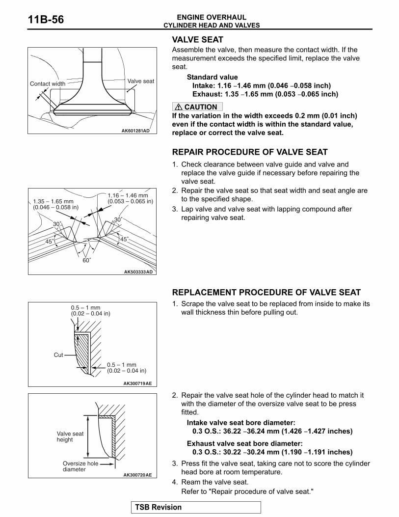
VALVE SEATAssemble the valve, then measure the contact width. If the measurement exceeds the specified limit, replace the valve seat.
Standard valueIntake: 1.16 − 1.46 mm (0.046 − 0.058 inch)Exhaust: 1.35 − 1.65 mm (0.053 − 0.065 inch)
CAUTIONIf the variation in the width exceeds 0.2 mm (0.01 inch) even if the contact width is within the standard value, replace or correct the valve seat.
REPAIR PROCEDURE OF VALVE SEAT1. Check clearance between valve guide and valve and
replace the valve guide if necessary before repairing the valve seat.
2. Repair the valve seat so that seat width and seat angle are to the specified shape.
3. Lap valve and valve seat with lapping compound after repairing valve seat.
REPLACEMENT PROCEDURE OF VALVE SEAT1. Scrape the valve seat to be replaced from inside to make its
wall thickness thin before pulling out.
2. Repair the valve seat hole of the cylinder head to match it with the diameter of the oversize valve seat to be press fitted.
Intake valve seat bore diameter:0.3 O.S.: 36.22 − 36.24 mm (1.426 − 1.427 inches)
Exhaust valve seat bore diameter:0.3 O.S.: 30.22 − 30.24 mm (1.190 − 1.191 inches)
3. Press fit the valve seat, taking care not to score the cylinder head bore at room temperature.
4. Ream the valve seat.Refer to "Repair procedure of valve seat."
AK601281AD
Contact width Valve seat
AK503333AD
30˚
60˚
30˚
1.16 – 1.46 mm(0.053 – 0.065 in)
45˚45˚
1.35 – 1.65 mm(0.046 – 0.058 in)
AK300719AE
Cut
0.5 – 1 mm(0.02 – 0.04 in)
0.5 – 1 mm(0.02 – 0.04 in)
AK300720AE
Oversize holediameter
Valve seatheight
TSB Revision

CYLINDER HEAD AND VALVESENGINE OVERHAUL 11B-57
REPLACEMENT PROCEDURE OF VALVE GUIDE1. Pull out the valve guide with a press toward the cylinder
block side.2. Ream the valve guide hole of the cylinder head to match it
with the diameter of the oversize valve guide to be press fitted.CAUTION
Do not use a valve guide with the same size as that of the pulled out valve guide because it cannot be press fitted.
Valve guide bore diameter0.25 O.S.: 11.23 − 11.25 mm (0.442 − 0.443 inch)
3. Press fit the valve guide to the illustrated dimension.Standard value: 14.6 − 15.2 mm (0.57 − 0.60 inch)
NOTE: Press fit the valve guide from the cylinder head top surface.
4. After pressing fit the valve guide, insert a new valve to check for sliding.
AK703735AC
14.6 – 15.2 mm(0.57 – 0.60 in)
TSB Revision

OIL PUMP CHAINENGINE OVERHAUL11B-58
OIL PUMP CHAINREMOVAL AND INSTALLATION M1113033700312
Required Special Tools:• MB991346: Top Cover Wrench• MB991883: Flywheel Stopper
AK702225
26 ± 1 N·m19 ± 1 ft-lb
26 ± 2 N·m19 ± 1 ft-lb23 ± 2 N·m
17 ± 1 ft-lb
54 ± 5 N·m40 ± 3 ft-lb
32 ± 2 N·m24 ± 1 ft-lb
10 ± 2 N·m89 ± 17 in-lb
10 ± 2 N·m89 ± 17 in-lb
10 ± 2 N·m89 ± 17 in-lb
Apply engine oil toall moving partsbefore installation.
40 N·m30 ft-lb
130 N·m96 ft-lb→
40 N·m30 ft-lb
130 N·m96 ft-lb→
1
2
34
11
8
12
7
AC
1013
15
6
5
14
17
169
Removal steps 1. Silicon ring <TC-SST>
<<A>> >>E<< 2. Flywheel bolt <TC-SST>3. Flywheel hub <TC-SST>4. Flywheel <TC-SST>
<<A>> >>E<< 5. Flywheel bolt <M/T>6. Flywheel <M/T>
>>D<< 7. Rear oil seal8. Oil pump chain guide9. Oil pump tensioner lever
>>C<< 10. Oil pump chain<<B>> >>C<< 11. Oil pump sprocket
12. Oil pump case>>B<< 13. Crankshaft sprocket
14. Oil cooler by-pass valve<<C>> >>A<< 15. Ladder frame
16. Check valve17. Oil jet
Removal steps (Continued)
TSB Revision

OIL PUMP CHAINENGINE OVERHAUL 11B-59
REMOVAL SERVICE POINTS.
<<A>> DRIVE PLATE BOLT / FLYWHEEL BOLT REMOVAL1. Use special tool MB991883 to secure the drive plate or
flywheel.2. Remove the drive plate bolts or flywheel bolts.
.
<<B>> OIL PUMP SPROCKET REMOVALFix the oil pump sprocket with a special tool MB991346, loosen a center bolt, and remove the oil pump sprocket.
.
<<C>> LADDER FRAME REMOVAL1. Pry the illustrated position with a screwdriver.
2. If the ladder frame does not come off, insert a flat blade screwdriver into the gap between the ladder frame and bearing cap as shown in the illustration and lightly pry it to remove the ladder frame.
AK703300
MB991883
AC
AK703732AC
MB991346Oil pump sprocket
AK502755AF
AK502756
TSB Revision

OIL PUMP CHAINENGINE OVERHAUL11B-60
INSTALLATION SERVICE POINTS.
>>A<< LADDER FRAME INSTALLATIONCAUTION
Be sure to remove liquid gasket that has entered mounting holes.1. Completely remove liquid gasket adhering to the cylinder
block and ladder frame.CAUTION
Sufficiently check that there is no residual oil on the place where degreasing is performed. If fingerprints are left, do not touch it with bare hands after the degreasing, since the oils from your fingers will harm the seal ability.2. Degrease the surface where the liquid gasket is applied and
the contact surface between the cylinder block and ladder frame.
3. Squeeze liquid gasket (Three bond 1217G [Mitsubishi Part No.1000A923] or equivalent) of φ2.0 to 3.0 mm (0.08 to 0.12 inch) in thickness and apply it to the illustrated position of the ladder frame.
4. Tighten the ladder frame to the specified torque in the order shown in the illustration.
Specified torque: 26 ± 1 N⋅ m (19 ± 1 ft-lb)
.
AK702198AC
A-AA
A
A
3.0 mm (0.12 in)
0 – 2.0 mm(0 – 0.08 in)
1.0 mm (0.04 in)
AK702199AC
4
11 33
22 64
3 55
6
TSB Revision

OIL PUMP CHAINENGINE OVERHAUL 11B-61
>>B<< CRANKSHAFT SPROCKET INSTALLATION1. Wipe off the dirt on the crankshaft sprocket and the
crankshaft using a rag, and then remove the grease from the portion shown in the illustration.NOTE: Remove grease to prevent a drop in the coefficient of friction of the pressing portion caused by adhesion of oil.
2. Set the No. 1 piston at top dead center on the compression stroke.
3. Install the crankshaft sprocket to the crankshaft.
.
>>C<< OIL PUMP SPROCKET / OIL PUMP CHAIN INSTALLATION1. Set the No. 1 piston at top dead center on the compression
stroke.2. Using the special tool MB991346, install the oil pump
sprocket to the oil pump case.3. Install the oil pump chain to the crankshaft sprocket.4. Install the oil pump chain to the oil pump sprocket.
.
>>D<< REAR OIL SEAL CASE INSTALLATIONCAUTION
Be sure to remove liquid gasket that has entered mounting holes.1. Completely remove liquid gasket adhering to the cylinder
block, ladder frame and rear oil seal case.CAUTION
Sufficiently check that there is no residual oil on the place where degreasing is performed. If fingerprints are left, do not touch it with bare hands after the degreasing, since the oils from your fingers will harm the seal ability.2. Degrease the surface where the liquid gasket is applied and
the contact surface between the cylinder block and ladder frame.
AK603521Crankshaft sprocket
Crankshaft
AB
Enginefront
: Wipe clean with a rag.: Wipe clean with a rag and degrease.
AK703732AC
MB991346Oil pump sprocket
TSB Revision

OIL PUMP CHAINENGINE OVERHAUL11B-62
3. Apply a small amount of engine oil to the oil seal lip.CAUTION
Install the timing chain case within three minutes after applying liquid gasket.4. Squeeze liquid gasket (Three bond 1217G [Mitsubishi Part
No.1000A923] or equivalent) of φ2.0 to 3.0 mm (0.08 to 0.12 inch) in thickness and apply it to the illustrated position of the cylinder block and ladder frame.
5. Install the rear oil seal case aligned with the locating pin and tighten it to the specified torque.
Specified torque: 10 ± 2 N⋅ m (89 ± 17 ft-lb)
.
>>E<< FLYWHEEL BOLT INSTALLATION1. Clean off sealant and oil of thread of crankshaft and flywheel
bolt.2. Use special tool MB991883 to secure the flywheel.
AK702200AC
B-B
A AA
A-A
BB
BB
A
1.0 mm (0.04 in)
0 – 2.0 mm(0 – 0.08 in)
AK702202AC
Locating pin
AK703299
MB991883
AC
TSB Revision

OIL PUMP CHAINENGINE OVERHAUL 11B-63
3. Apply engine oil to thread of crankshaft and bolt seat area of flywheel.
4. Apply the sealant (Three bond 1324 or equivalent) to the thread of flywheel bolt.
5. Tighten flywheel bolts to temporary torque 40 N⋅ m (30 ft-lb) in the order shown to illustration.
6. Tighten flywheel bolts to specified torque in the order shown in the illustration.
Specified torque: 130 N⋅ m (96 ft-lb)
INSPECTIONM1113033800030
.
OIL JET1. Check the oil jet and check valve for clogging2. Check the oil jet for damage and deformation
.
OIL COOLER BY-PASS VALVE1. Make sure that valve moves smoothly.2. Ensure that the dimension L measures the standard value
under normal temperature and humidity.Standard value: 34.5 mm (1.358 inches)
3. The dimension must be the standard value when measured after the valve has been dipped in 97 to 103° C (207 to 217° F) oil.
Standard value: 40.0 mm (1.575 inches)
AK600847AC
AK603576
1 2
3
4
56
7
AB
AK703183
AK703184
L
ACValve
TSB Revision

PISTON AND CONNECTING RODENGINE OVERHAUL11B-64
PISTON AND CONNECTING RODREMOVAL AND INSTALLATION
M1113008402308
Required Special Tools:• MB992236: Circlip Installer• MD998780: Piston Setting Tool
AK702224
5.0 N·m44 in-lb
20 N·m15 ft-lb1
2
3
4
5
6 7
8
11
12
14
AC
9
10
13
Apply engine oil toall moving partsbefore installation.
→ → +90˚
Removal steps >>G<< 1. Connecting rod cap bolt
<<A>> >>F<< 2. Connecting rod cap>>E<< 3. Connecting rod bearing>>E<< 4. Connecting rod bearing>>D<< 5. Piston connecting rod assembly>>C<< 6. Piston ring No. 1>>C<< 7. Piston ring No. 2
>>B<< 8. Oil ring<<B>> >>A<< 9. Circlip<<B>> >>A<< 10. Circlip<<B>> >>A<< 11. Piston pin
12. Piston13. Bushing14. Connecting rod
Removal steps (Continued)
TSB Revision

PISTON AND CONNECTING RODENGINE OVERHAUL 11B-65
REMOVAL SERVICE POINTS.
<<A>> CONNECTING ROD REMOVALMark the connecting rod on the big end with the cylinder num-ber it is being removed from.
.
<<B>> SNAP RING REMOVALInsert the precise screwdriver into the service hole to remove the snap ring.
.
<<C>> PISTON PIN REMOVALCAUTION
The clearance between the piston and the piston pin is a tight fit at room temperature. Therefore, be sure the heat the piston before pulling out the piston pin. Use care sine the piston is hot after heating.1. Into each container, pour enough engine oil to completely
cover a piston.2. Heat the engine oil to warm the piston to approximately
70° C (158° F), and then remove the piston pin.
AK703289AE
Cylinder number
AK702192AC
Service hole
AK602540
70˚C(158˚F)
AE
Engine oil
TSB Revision

PISTON AND CONNECTING RODENGINE OVERHAUL11B-66
INSTALLATION SERVICE POINTS.
>>A<< PISTON PIN INSTALLATION1. When replacing a piston, check the cylinder bore size mark
stamped on the illustrated position of the cylinder block and select a corresponding piston from the table below.
NOTE: The piston size mark is indicated on the piston top face.
CAUTIONThe clearance between the piston and the piston pin is a tight fit at room temperature. Therefore, be sure the heat the piston before pulling out the piston pin. Use care sine the piston is hot after heating.2. Into each container, pour enough engine oil to completely
cover a piston.3. Heat the engine oil to warm the piston to approximately
70° C (158° F), and then remove the piston pin.4. Sufficiently apply the engine oil to the outer circumference of
piston pin and the small end hole of connecting rod.
Cylinder bore size mark
Piston size mark
A A
B B or none
C C
AK702191AD
No.1
No.2
No.3
No.4
Engine front
AK702190AD
Piston size mark
Frontmark
AK600723AE
Engine oil70˚C(158˚F)
TSB Revision

PISTON AND CONNECTING RODENGINE OVERHAUL 11B-67
5. Put the front mark of connecting rod and the front mark of piston toward the same side, and then insert the piston pin.
6. Install the circlip to the piston according to the following procedure:
(1) With the open side facing upward, install the new circlip to the special tool MB992236.
(2) Align the open side of circlip with the piston groove, and then set the circlip together with the special tool MB992236.
(3) Install the guide A (φ21.9 mm [0.88 inch]), to the push rod of special tool MD998780.
(4) Push the opposite side of open side with the special tool MD998780, and install the circlip to the piston groove.
(5) Make sure the circlip is seated into the groove. (6) Unless seated into the groove, the circlip must be pushed
with the special tool MD998780 again to be seated into the groove.
AK702189AC
Front mark
AK703270AC
MB992236
Circlip
Open side
AK703271AC
MB992236
Piston
Circlip
Groove
Set the open side of the circlip to the groove
AK703185AC
MD998780
Push rod
Guide A Ø21.9 mm (0.86 in)
AK703272AC
MB992236
MD998780
Circlip
TSB Revision

PISTON AND CONNECTING RODENGINE OVERHAUL11B-68
7. Check that the piston moves smoothly.
.
>>B<< OIL RING INSTALLATION1. Assemble the spacer of the oil ring into the piston ring
groove. Then, assemble the upper side rail, and after this assemble the lower side rail.NOTE: Install the side rail and end gap of the spacer so that they are at the position as shown in the illustration.NOTE: New spacers and side rails are an identified by color marks as follows:
CAUTIONThe side rail may be broken if its end gap is widened by a ring expander as in other piston rings.2. When assembling the side rail, push it by fingers, after fitting
one end of the side rail into the piston groove, for easy assembly.
3. After assembling the oil ring into the piston, make sure that the side rail turns smoothly to either direction.
.
>>C<< PISTON RING NO. 2 / PISTON RING NO. 1 INSTALLATIONUse a piston ring expander to assemble piston rings with their identification marks facing upward. Piston rings can be assem-bled by hand without using the piston ring expander.
AK702201
Size Color markStandard Non mark
0.25 mm (0.010 inch) oversize
Two blue
AK400536
Uppersiderail gap
AC
Lowersiderail gap
Spacer gap
AK304891
AK304892AD
Piston ringexpander
TSB Revision

PISTON AND CONNECTING RODENGINE OVERHAUL 11B-69
Identification markNo. 1 ring: 1RNo. 2 ring: 2R
NOTE: Each of the available piston rings has a size mark as follows:
.
>>D<< PISTON CONNECTING ROD ASSEMBLY INSTALLATION1. Apply a sufficient amount of engine oil to the circumference
of the piston, piston rings and oil ring.2. Arrange end gap positions of piston rings and oil ring (side
rail and spacer) as shown in the illustration.3. Insert the piston and connecting rod assembly from the top
surface of the cylinder block with the front mark of the piston top face facing toward the timing chain side.
CAUTIONDriving it in hard causes breakage of piston rings and damage to the crank pin.4. Firmly tighten the piston ring with a ring band and insert the
piston and connecting rod assembly.
.
Size Size markStandard No mark
0.25 mm (0.010 inch) oversize
25AK600791
No. 2
No. 1
Identification mark
AC
AK400403
No.1Side rail
Side railAC
Piston pin
No.2
AK502730
TSB Revision

PISTON AND CONNECTING RODENGINE OVERHAUL11B-70
>>E<< CONNECTING ROD BEARING INSTALLATION1. When replacing a connecting rod bearing, select the bearing
corresponding to the crankshaft pin outside diameter according to the crankshaft pin identification in the table below.
2. An identification mark of a crankshaft is stamped at the illustrated position by No.
3. A connecting rod bearings an identification mark at the illustrated position.
.
>>F<< CONNECTING ROD CAP INSTALLATION 1. Assemble the bearing cap on the connecting rod by aligning
it with the mark put during removal. If a new connecting rod without a mating mark is used, assemble so that the detent notch of the bearing is on the same side as illustrated.
Crankshaft pin Connecting rod bearing
Identification mark
Journal diameter mm (in)
Identification mark
1 51.966 − 51.972 (2.0459 − 2.0461)
1
2 51.960 − 51.966 (2.0457 − 2.0459)
2
3 51.954 − 51.960 (2.0454 − 2.0457)
3
AK702193AD
No.1
No.2
No.3
No.4
Crankshaft pin identification stamp position
Crankshaftfront end
AK700793AD
Identificationmark
AK703289AD
Cylinder number
Notch
TSB Revision
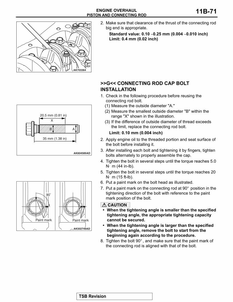
PISTON AND CONNECTING RODENGINE OVERHAUL 11B-71
2. Make sure that clearance of the thrust of the connecting rod big end is appropriate.
Standard value: 0.10 − 0.25 mm (0.004 − 0.010 inch)Limit: 0.4 mm (0.02 inch)
.
>>G<< CONNECTING ROD CAP BOLT INSTALLATION1. Check in the following procedure before reusing the
connecting rod bolt.(1) Measure the outside diameter "A."(2) Measure the smallest outside diameter "B" within the
range "X" shown in the illustration.(3) If the difference of outside diameter of thread exceeds
the limit, replace the connecting rod bolt.Limit: 0.10 mm (0.004 inch)
2. Apply engine oil to the threaded portion and seat surface of the bolt before installing it.
3. After installing each bolt and tightening it by fingers, tighten bolts alternately to properly assemble the cap.
4. Tighten the bolt in several steps until the torque reaches 5.0 N⋅ m (44 in-lb).
5. Tighten the bolt in several steps until the torque reaches 20 N⋅ m (15 ft-lb).
6. Put a paint mark on the bolt head as illustrated.7. Put a paint mark on the connecting rod at 90° position in the
tightening direction of the bolt with reference to the paint mark position of the bolt.CAUTION
• When the tightening angle is smaller than the specified tightening angle, the appropriate tightening capacity cannot be secured.
• When the tightening angle is larger than the specified tightening angle, remove the bolt to start from the beginning again according to the procedure.
8. Tighten the bolt 90° , and make sure that the paint mark of the connecting rod is aligned with that of the bolt.
AK703364
AK604589AD
20.5 mm (0.81 in)
35 mm (1.38 in)
ABB
X
AK502749
90˚
Paint mark
AD
Paint mark
TSB Revision

PISTON AND CONNECTING RODENGINE OVERHAUL11B-72
INSPECTIONM1113008501788
.
PISTON RINGS1. Check clearance between piston rings and ring grooves. If
the limit is exceeded, replace piston rings or piston, or both.Standard value:
No. 1 ring: 0.02 − 0.06 mm (0.001 − 0.002 inch)No. 2 ring: 0.02 − 0.06 mm (0.001 − 0.002 inch)
Limit: 0.10 mm (0.004 inch)
2. Put piston rings into the cylinder bore, press them against the piston top face, and push them in. After achieving squareness, measure the end gap with a thickness gauge. If the end gap is excessive, replace piston rings.
Standard value:No. 1 ring: 0.18 − 0.28 mm (0.007 − 0.011 inch)No. 2 ring: 0.28 − 0.43 mm (0.011 − 0.017 inch)Oil ring: 0.10 − 0.34 mm (0.004 − 0.013 inch)
Limit:No. 1 ring: 0.8 mm (0.03 inch)No. 2 ring: 0.8 mm (0.03 inch)Oil ring: 1.0 mm (0.04 inch)
.
CRANKSHAFT PIN OIL CLEARANCE (PLASTIGAGE METHOD)1. Wipe oil off the crankshaft pin and connecting rod bearing.2. Place a plastigage in length equal to the bearing width on
the pin shaft straight in alignment with the shaft center.3. Carefully install the connecting rod cap and tighten bolts to
the specified torque of 5.0 N⋅ m (44 in-lb) → 20 N⋅ m (15 ft-lb) → +90° .
4. Remove bolts and gently remove the connecting rod cap.
AK502751
AK603466
Please down ring with piston
End gapPiston ring
AC
AK703363AC
Plastigage
TSB Revision

CRANKSHAFT AND CYLINDER BLOCKENGINE OVERHAUL 11B-73
5. Measure the crushed plastigage width (area most widely crushed) using a scale printed on the plastigage bag.
Standard value: 0.038 − 0.069 mm (0.0015 − 0.0027 inch)Limit: 0.10 mm (0.004 inch)
CRANKSHAFT AND CYLINDER BLOCKREMOVAL AND INSTALLATION
M1113008703777
AK703362AC
Plastigage
AK702223AC
6
→ +90˚9.0 ± 2.0 N·m80 ± 17 in-lb
7
8
11 ± 1 N·m98 ± 8 in-lb
9
5 4
3
1
237.2 ± 2.0 N·m28 ± 1 ft-lb → +90˚
Apply engine oil toall moving partsbefore installation.
TSB Revision

CRANKSHAFT AND CYLINDER BLOCKENGINE OVERHAUL11B-74
REMOVAL SERVICE POINT.
<<A>> CRANKSHAFT REMOVALAfter removing the crankshaft with the crankshaft sensing ring attached, temporarily place it on a V-block to prevent teeth of the sensing ring from deforming.NOTE: If a tooth bends, be sure to replace the crankshaft sens-ing ring with a new one.
INSTALLATION SERVICE POINTS.
>>A<< CRANKSHAFT SENSING RING INSTALLA-TIONTighten crankshaft sensing ring bolts to the specified torque in the tightening order shown in the illustration.
Specified torque: 11 ± 1 N⋅ m (98 ± 8 in-lb)
.
>>B<< THRUST BEARING INSTALLATION 1. Install the thrust bearing on the No. 3 bearing on the cylinder
block side. Application of engine oil makes the installation easier.
2. Install the thrust bearing so that the grooved side is on the crankshaft weight side.
.
Removal steps >>E<< 1. Crankshaft bearing cap bolt <M8>>>E<< 2. Crankshaft bearing cap bolt <M10>>>E<< 3. Crankshaft bearing cap>>D<< 4. Crankshaft bearing lower
<<A>> 5. Crankshaft
>>C<< 6. Crankshaft bearing upper>>B<< 7. Thrust bearing>>A<< 8. Crankshaft sensing ring
9. Cylinder block
Removal steps (Continued)
AK502865AD
1
2
4 3
Crankshaft sensing ring
AK502394
Groove
AE
TSB Revision

CRANKSHAFT AND CYLINDER BLOCKENGINE OVERHAUL 11B-75
>>C<< CRANKSHAFT BEARING UPPER INSTALLATION1. When replacing the crankshaft bearing upper, select a
bearing with the size corresponding to the cylinder block journal diameter in the table below.
2. The crankshaft bearing upper has an identification colour at the illustrated position.
3. Install the selected crankshaft bearing upper..
AK702191AE
No.1
No.2
No.3
No.4
No.5
Engine front
AK900345
Identificationcolour
AB
Cylinder block Crankshaft bearingIdentification mark Journal diameter mm (in) Identification colourNo. 1, 2, 4, 5 No. 3 No. 1, 2, 4, 5 No. 31 0 56.000 − 56.006 (2.2047 − 2.2050) Black Red2 1 56.006 − 56.012 (2.2050 − 2.2052) None Black3 2 56.012 − 56.018 (2.2052 − 2.2054) Green None
TSB Revision

CRANKSHAFT AND CYLINDER BLOCKENGINE OVERHAUL11B-76
>>D<< CRANKSHAFT BEARING LOWER INSTALLATION1. When replacing the crankshaft bearing lower, select a
bearing with the size corresponding to the crankshaft journal diameter in the table below.
2. The crankshaft bearing lower has an identification colour at the illustrated position.
3. Install the selected crankshaft bearing lower.
.
AK702193AE
No.1
No.2
No.3
No.4
No.5
Crankshaft journal identification stamp position
Crankshaftfront end
AK900344
Identificationcolour
AB
Crankshaft Crankshaft bearingIdentification mark Journal diameter mm (in) Identification colourNo. 1, 2, 4, 5 No. 3 No. 1, 2, 4, 5 No. 30 8 51.985 − 51.988 (2.0467 − 2.0468) Red Brown1 9 51.982 − 51.985 (2.0465 − 2.0467) Black Yellow2 0 51.979 − 51.982 (2.0464 − 2.0465) None Red3 1 51.976 − 51.979 (2.0463 − 2.0464) Green Black4 2 51.973 − 51.976 (2.0462 − 2.0463) Blue None
TSB Revision

CRANKSHAFT AND CYLINDER BLOCKENGINE OVERHAUL 11B-77
>>E<< CRANKSHAFT BEARING CAP / CRANKSHAFT BEARING CAP BOLT INSTALLATION1. Install the crankshaft bearing cap with reference to the
identification mark as illustrated.
2. Before using the crankshaft bearing cap bolt again, carry out the check according to the following procedure:(1) Measure the 2 points on the outside diameter of thread
as shown in the illustration. (2) When the difference between the measured outside
diameters is beyond the limit value, replace the crankshaft bearing cap bolt.
Limit valueM10: 0.15 mm (0.006 inch)M8: 0.10 mm (0.004 inch)
3. Apply engine oil to the threaded portion and seat surface of the bolt.
4. Tighten crankshaft bearing cap bolts to the specified torque according to the tightening order.
Specified torqueM10: 37.2 ± 2.0 N⋅ m (27 ± 1 ft-lb)M8: 9.0 ± 2.0 N⋅ m (80 ± 17 in-lb)
5. Make a paint mark on the head of each bolt.6. Make a paint mark on the bearing cap 90° from the paint
mark made on the bolt, in the direction of tightening the bolt.CAUTION
• When the tightening angle is smaller than the specified tightening angle, the appropriate tightening capacity cannot be secured.
• When the tightening angle is larger than the specified tightening angle, remove the bolt to start from the beginning again according to the procedure.
7. Turn each bolt 90° in the tightening sequence specified in step 1, and make sure that the paint marks on the bolt and cap are aligned.
AK702195AD
Timing chain side
10
11
12
15
16
19
20
13
14
5
6
91
2
3
4
7
8
17
18
10
11
12
15
16
19
20
13
14
5
6
91
2
3
4
7
8
17
18
AK702196
77 mm(3.03 in)
46 mm(1.81 in)
AC
44 mm(1.73 in)
23 mm(0.91 in)
<M10>
<M8>
A B
A B
AK703290
90˚
AC
Paint mark Paint mark
TSB Revision

CRANKSHAFT AND CYLINDER BLOCKENGINE OVERHAUL11B-78
8. Check end play of the crankshaft after installing the crankshaft bearing cap. If the end play exceeds the limit, replace the thrust bearing.
Standard value: 0.05 − 0.25 mm (0.002 − 0.010 inch)Limit: 0.4 mm (0.02 inch)
INSPECTIONM1113008801767
.
CRANKSHAFT OIL CLEARANCE (PLASTIGAGE METHOD)Oil clearance can be easily measured by using a "plastigage."When using a "plastigage," perform measurement in the follow-ing procedure.1. Fully wipe oil off the outside diameter of the crankshaft and
inside diameter of the bearing.2. Assemble the crankshaft.3. Place a plastigage in length equal to the bearing width on
the journal shaft straight in alignment with the shaft center.4. Carefully install the bearing cap and tighten the bolt
according to the main point of installation >>B<<.5. Remove the bolt, and then carefully remove the crankshaft
bearing cap.
6. Measure the crushed plastigage width (area most widely crushed) using a scale printed on the plastigage bag.
Standard value: No. 1, 2, 4, 5: 0.039 − 0.065 mm (0.0015 − 0.0026 inch) No. 3: 0.051 − 0.077 mm (0.0020 − 0.0030 inch)
Limit: 0.10 mm (0.004 inch)
.
AK503375
AK703296AC
Plastigage
AK703297
TSB Revision

CRANKSHAFT AND CYLINDER BLOCKENGINE OVERHAUL 11B-79
CYLINDER BLOCK1. Visually check the cylinder block for scratch, rust and
corrosion. Use a flaw detecting agent to check for cracks. If it is found faulty, repair or replace it.
2. Measure distortion on the top surface of the cylinder block using a straight edge and thickness gauge.If distortion exceeds the limit, grind and repair it.A gasket or the like must not be adhered to the top surface of the cylinder block during measurement.
Distortion on bottomStandard value: Within 0.05 mm (0.002 inch)Limit: 0.2 mm (0.01 inch)Grinding limit: 0.2 mm (0.01 inch)
3. Check the cylinder bore for scoring or seizure. If faulty, correct (boring) or replace.
4. Measure the bore and cylindricity of the cylinder using a cylinder gauge.If the cylinder is excessively worn, repair the cylinder and replace the piston and piston rings.Measuring points are as shown in the illustration.
Standard valueCylinder bore: 86 mm (3.4 inches)Cylindricity: 0.010 mm or less (0.0004 inch)
.
AK502746
AK703729AC
45 mm(1.78 in)
12 mm(0.47 in)
100 mm(3.94 in)
TSB Revision

CRANKSHAFT AND CYLINDER BLOCKENGINE OVERHAUL11B-80
BORING CYLINDERS1. Oversize pistons should be based on the largest bore
cylinder.
NOTE: The size mark is stamped on the piston top.2. In case of 0.25 mm (0.010 inch) oversized piston, a hole
shall be bored through the cylinder block so that the clearance can have the standard value. The standard measuring point for the outside piston diameter is at shown in the illustration.
3. Based on the measured piston outside diameter (O.D.), calculate the boring finish dimension.
Boring finish dimension = Piston O.D. + 0.03 − 0.05 mm (0.001 − 0.002 inch) <Clearance between piston O.D. and cylinder> − 0.02 mm (0.001 inch) <honing margin>
4. Bore each cylinders to the calculated boring finish dimension.CAUTION
To prevent distortion caused by heat increased during bor-ing, bore the cylinders in the following order: No.2, No.1, No.3.5. Hone the cylinders to the final finish dimension (piston O.D.
+ piston-to-cylinder clearance).6. Check the clearance between the pistons and cylinders.
Standard value: 0.03 − 0.05 mm (0.001 − 0.002 inch)NOTE: When boring cylinders, finish all of four cylinders to the same oversize. Do not bore only one cylinder to an over-size.
Size Size mark0.25 mm (0.010 inch) oversize
25
AK703827AB12 mm (0.5 in)
TSB Revision


![Untitled Document [outlander.kiev.ua]outlander.kiev.ua/manuals/Mitsubishi Outlander Manual/Outlander... · HOW TO USE THIS MANUAL 11B-2 ENGINE OVERHAUL HOW TO USE THIS MANUAL M1113025100155](https://static.fdocuments.in/doc/165x107/5b8385527f8b9a31608d753d/untitled-document-outlander-manualoutlander-how-to-use-this-manual-11b-2.jpg)