GROUNDWATER SAMPLING GUIDELINES - …/media/Publications/669.pdf · Environment Protection...
40
GROUNDWATER SAMPLING GUIDELINES Environment Protection Authority State Government of Victoria April 2000
Transcript of GROUNDWATER SAMPLING GUIDELINES - …/media/Publications/669.pdf · Environment Protection...

GROUNDWATER SAMPLING GUIDELINES
Environment Protection AuthorityState Government of Victoria
April 2000

Environment Protection Authority
ii
GROUNDWATER SAMPLING GUIDELINES
Published under section 13 (1) (i) of the Environment Protection Act 1970
Acknowledgments:EPA gratefully acknowledges the contributions of Mr Stephen Hancock, Mr Anthony Lane,Mr John Leonard, Mr Andrew Shugg and Dr Tamie Weaver
Environment Protection Authority40 City RoadSouthbank Victoria 3006Australia
Printed on recycled paper
Publication 669
© Environment Protection Authority, April 2000
ISBN 0 7306 7563 7

Groundwater Sampling Guidelines
iii
FOREWORD
Over the past decade, the assessment of environmental quality has become a more prominent andfamiliar activity. More recently, there has been an increased emphasis on groundwater qualityinvestigations (including sampling).
The public release of these guidelines contributes to EPA’s broader strategic goal of establishingmeasures that:
� ensure current contamination of land and groundwater is managed to maximise usefulness of theresource
� protect land and groundwater resources from pollution in the future.
These guidelines aim to assist those sampling groundwater to collect representative samples by:
� highlighting important issues
� identifying objectives and key measures to achieve those objectives
� identifying information and source materials.
Implementation of these guidelines will enable those involved in groundwater sampling to reduce thepotential for error, allowing subsequent groundwater management decisions to be based on‘representative’ groundwater quality data. This is especially important when considering that in thelong-term inadequate groundwater sampling can prove to be costly both in terms of environmental andfinancial outcomes.
These guidelines will be reviewed regularly and updated as necessary on the basis of operatingexperience. Users are encouraged to provide comment to assist in this review process.
I commend these guidelines to those involved in groundwater investigations and urge their adoptionand implementation in the interests of improved environmental performance.

Environment Protection Authority
iv
CONTENTS
FOREWORD............................................................................................................................... iii
1. INTRODUCTION ................................................................................................................... 1
1.1 Statutory framework....................................................................................................... 1
1.2 Background and purpose of guidelines............................................................................ 1
1.3 Who needs these guidelines? .......................................................................................... 2
1.4 Additional guidance documents ...................................................................................... 2
2. OBJECTIVES OF GROUNDWATER SAMPLING................................................................. 3
2.1 Groundwater sampling program...................................................................................... 3
2.2 Hydrogeological assessment ........................................................................................... 33. KEY FACTORS THAT CAN INFLUENCE GROUNDWATER SAMPLES
(PRE-SAMPLING) .................................................................................................................. 5
3.1 Drilling........................................................................................................................... 5
3.2 Installation ..................................................................................................................... 5
3.3 Bore development........................................................................................................... 6
3.4 Further information ........................................................................................................ 7
4. GROUNDWATER SAMPLING.............................................................................................. 8
4.1 Approved samplers......................................................................................................... 8
4.2 Planning and preparation ................................................................................................ 8
4.3 Quality Assurance and Quality Control (in-field) ............................................................ 8
4.4 Groundwater level measurements ..................................................................................11
4.5 Purging..........................................................................................................................12
4.6 Field measurements .......................................................................................................15
4.7 Sample collection ..........................................................................................................16
4.8 Filtration of Groundwater Samples ................................................................................194.9 Sample containers, preservation, labelling and logging, transport and holding
times .............................................................................................................................21
4.10 Decontamination ...........................................................................................................22
4.11 Health and safety...........................................................................................................22
4.12 Documentation ..............................................................................................................22
4.13 Reporting groundwater sampling results ........................................................................23
4.14 Sampling for non-aqueous phase liquids (NAPL)...........................................................24
GLOSSARY ................................................................................................................................25
REFERENCES ............................................................................................................................35
APPENDIX A: SAMPLING EQUIPMENT .................................................................................27
APPENDIX B: GROUNDWATER SAMPLING DEVICE MATRIX ..........................................31
APPENDIX C: FIELD RECORD SHEETS..................................................................................32
APPENDIX D: FIELD EQUIPMENT CHECKLIST....................................................................33
APPENDIX E: CHAIN-OF-CUSTODY FORM...........................................................................34
FIGURES
Figure1: Groundwater monitoring bore..................................................................................... 6
Figure 2: Groundwater flow through a bore .............................................................................14
Groundwater Sampling Guidelines
1
1. INTRODUCTION
Groundwater is an important resource inVictoria. In addition to being a source ofpotable water supply, irrigation water,stockwater and water for other uses,groundwater plays a significant role in themaintenance of base flows for manywaterways and wetlands. The StateGovernment has recognised the need to protectthe quality of groundwater (and its beneficialuses) by declaring the State EnvironmentProtection Policy (Groundwaters of Victoria)in December 1997. These guidelines areproduced as part of the implementation of thatpolicy.
In order to protect the beneficial uses ofgroundwater from pollution, it is important toaccurately determine and report itscomposition. The collection of groundwatersamples can be a significant source of error ingroundwater quality data. These guidelineshave been developed to assist those involved ingroundwater sampling to reduce the potentialfor error, allowing subsequent groundwatermanagement decisions to be based on‘representative’ groundwater quality data.
1.1 Statutory frameworkVictoria’s environment protection system isbased on the Environment Protection Act 1970.The Act establishes the EnvironmentProtection Authority (EPA), defines EPA’spowers, duties and functions and contains anumber of instruments to minimise pollution,wastes and environmental risks. Theseinstruments include State EnvironmentProtection Policies (SEPPs), Industrial WasteManagement Policies (IWMPs), worksapprovals, licences and pollution abatementnotices, other notices and environmentalaudits.
The key SEPPs that are directly relevant to theprotection of groundwater quality in Victoriainclude:
• SEPP (Groundwaters of Victoria) 1997
• SEPP (Siting and Management ofLandfills Receiving Municipal Waste)1991.
The following documents also contribute to theprotection of groundwater quality in Victoria:
• the National Environment Protection(Assessment of Site Contamination)Measure.
• the draft SEPP (Prevention andManagement of Contamination of Land).This document is currently beingfinalised.
1.2 Background and purpose of guidelines
Groundwater sampling and analysis isundertaken to:
• determine background groundwaterquality and the relevant beneficial usesof groundwater
• detect any contamination and changes ingroundwater quality
• determine the extent and degree ofexisting groundwater contamination
• evaluate the environmental performanceof activities with potential tocontaminate groundwater
• assess the quality of an existing orpotential groundwater resource.
According to Barcelona (1985), significanterrors in groundwater data arise from themethods used in field sampling. It is thereforeessential that groundwater sampling isundertaken in a manner that allows subsequentanalysis to provide accurate data on which tobase groundwater management decisions,including critical decisions regarding themanagement of contaminated or potentiallycontaminated sites.

Environment Protection Authority
2
The key objective of this document is to fosterpractices that will assist with accurate andconsistent determination of chemical andbiological indicators of groundwater. Suchpractices will ensure that groundwater samplesare representative of groundwater in theaquifer and will remain representative untilanalytical determinations or measurements aremade.
These guidelines reflect current internationalgood practice and provide an outline of thecritical issues that should be considered beforeand during groundwater sampling. Theyidentify objectives and key measures by whichthe objectives can be met, focus on areas forinvestigation and identify relevant informationand source materials.
Individual components of groundwatersampling should be assessed for their impacton analytical results and the overall samplingtechnique used should be commensurate withthe required sensitivity or use of the data.
These guidelines are suited to activities wherea considerable amount of in-field experienceand professional judgement are required. Assuch, they do not provide detailed technicaladvice and are not intended to be a substitutefor technical expertise and professionaljudgement.
Although these guidelines are not mandatory,the potential exists for regulatory authorities tocall up such a document in approvals, licences,notices or permits.
1.3 Who needs these guidelines?
These guidelines are primarily intended for useby those collecting groundwater samples forchemical analysis (ie environmentalconsultants, officers of EPA and otherprotection agencies and site owner/occupiers).These guidelines may also be a usefulreference for protection agencies that requiregroundwater sampling to be undertaken byothers.
1.4 Additional guidance documents
Other relevant documents that provideinformation on aspects of groundwatersampling and hydrogeology include:
1. EPA 2000, HydrogeologicalAssessments (Groundwater Quality),EPA Publication 668, Melbourne,Environment Protection Authority(Victoria) (forthcoming).
2. EPA 2000, A Guide to the Sampling andAnalysis of Waters, Wastewaters, Soilsand Wastes, 7th Edition, EPAPublication 441, Melbourne,Environment Protection Authority(Victoria).
3. Standards Australia AS/NZ,Australian/New Zealand Standard 1998,Water Quality – Sampling Part 1:Guidance on the Design of SamplingPrograms, Sampling Techniques and thePreservation and Handling of Samples.
4. Standards Australia AS/NZ,Australian/New Zealand Standard 1998,Water Quality – Sampling Part 11:Guidance on Sampling ofGroundwaters.
The two EPA documents, HydrogeologicalAssessments (Groundwater Quality) and AGuide to the Sampling and Analysis of Waters,Wastewaters, Soils and Wastes are referred toextensively. It is recommended that they beread in conjunction with this document.

Groundwater Sampling Guidelines
3
2. OBJECTIVES OFGROUNDWATERSAMPLING
The primary objective of any groundwater(quality) sampling is to produce groundwatersamples that are representative of groundwaterin the aquifer and will remain representativeuntil analytical determination or measurementsare made.
2.1 Groundwater sampling program
A groundwater sampling program is adocument describing the procedures used tocollect, handle and analyse groundwatersamples to achieve groundwater samplingobjectives. A groundwater sampling programshould be prepared before sampling, takinginto account site specific considerations (egaquifer type and contaminants).
When designing a groundwater samplingprogram it is essential that the overallobjectives of the monitoring program beestablished and considered. The objectives ofmonitoring programs may vary, from long-term groundwater monitoring at landfills orwastewater treatment plants, establishing thestatus of groundwater contamination atcontaminated sites, to determining regional andambient groundwater quality.
A groundwater sampling program should bescientifically designed and statistically valid.For further information on program design seeEPA Publication 668 HydrogeologicalAssessments (Groundwater Quality).
Groundwater sampling program
Objective
To enable the objectives of the groundwatermonitoring program to be met.
Key measures
Prepare a groundwater sampling programdescribing the procedures used to collect,handle and analyse groundwater samples.
2.2 Hydrogeological assessment
Before developing a groundwater samplingprogram, a hydrogeological desk study shouldbe undertaken (as a minimum).
Ideally, the person responsible for samplingshould be aware of the necessary backgroundinformation to be able to make an informeddecision about the sampling program.
The following background information mustbe obtained and considered as a minimum:
• Site history: contaminants of concernand potential for contamination,including, for example, contaminant use,past practices and incident history.
• Hydrogeological setting: aquifer typeand configuration, groundwater flowdirections and rates, vulnerability of theaquifer system to contamination.
• Previous field investigations: borelogs, depth and length of screenedinterval, depth and construction details,past water level measurements.
It is not intended for this guideline to discusshydrogeological assessments in any detail.EPA Publication 668, HydrogeologicalAssessments (Groundwater Quality) should bereferred to for further details.
Environment Protection Authority
4
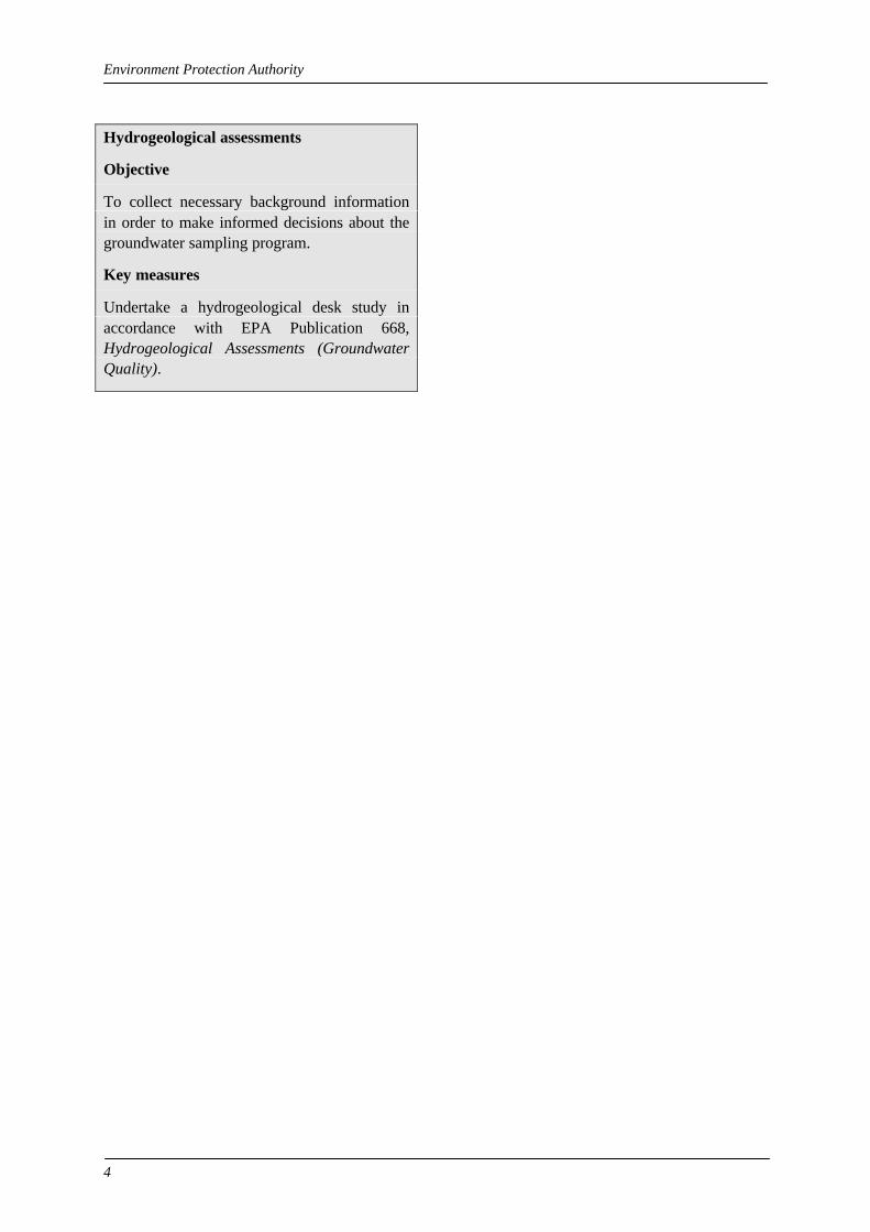
Hydrogeological assessments
Objective
To collect necessary background informationin order to make informed decisions about thegroundwater sampling program.
Key measures
Undertake a hydrogeological desk study inaccordance with EPA Publication 668,Hydrogeological Assessments (GroundwaterQuality).
Groundwater Sampling Guidelines
5
3. KEY FACTORS THAT CAN INFLUENCE GROUNDWATER SAMPLES (PRE-SAMPLING)
Drilling, construction and development ofbores can have a fundamental effect on thequality of groundwater samples extracted fromthem, through the introduction of physical orchemical effects or unwanted residues.
Before sampling from a monitoring bore, theimpacts of drilling, construction anddevelopment need to be understood so that theappropriate sampling equipment andmethodology may be selected.
3.1 Drilling
3.2 Drilling techniques
Drilling techniques used for monitoring boreconstruction need to be carefully considered toreflect monitoring needs. Drilling techniquecan cause smearing (eg rotary auger) andcompaction (eg cable tool) of borehole wallsand may also cause transport of geologicalformation materials and drilling fluids intodifferent zones. This can result in groundwaterand contaminant pathway blockage, therebyexcluding contamination from the monitoredmaterial.
Developing the bore may reduce the impacts ofdrilling technique – section 3.3 provides moreinformation on bore development.
3.1.2 Drilling fluids
Drilling fluids are generally used during thedrilling process to remove cuttings from theborehole, to clean and cool the bit, reducefriction between the drill string and the sides ofthe borehole and to hold the borehole openduring the drilling operation.
Drilling fluids used include air, water andspecific drilling mud formulations or native
clay slurries. They can have a range of effectson groundwater quality:
• Air may cause oxidation andprecipitation of analytes of interest, suchas dissolved metals (egferric→oxidation→ferrous) or, ifcontaminated with lubricants necessaryfor compressor operation, may introducehydrocarbons into groundwater.
• Air may also cause severe disturbance ofhydrochemical profiles in highlypermeable formations.
• Water may dilute or flush groundwaternear the bore, changing the chemistry ofthe groundwater.
• Water may also cause precipitation ofminerals, thereby blocking contaminantand groundwater pathways (ie pores andfractures).
• Mud may enter the formation and sealpreferential groundwater pathways, orclay particles within mud may sorbsome electrically charged contaminants(eg dissolved metals).
• The use of additives in mud (egsurfactants and drilling detergents) toovercome drilling difficulties increasesthe potential for introduction of physicaland chemical changes.
Since these effects are frequently permanent, itis important to record drilling method, fluidsused and details of bore development beforesampling.
3.2 Installation
3.2.1 Casing and screen
Casing and screen materials may beincompatible with the immediate groundwaterenvironment. Incompatible casing and screenmaterial may result in either leaching orsorption of analytes of interest, whiledesorption of analytes of interest may occurshould water quality change. Diffusion of
Environment Protection Authority
6
organics may also occur through polymericcasing materials.
For example, in extreme cases acidicenvironments may cause corrosion of metalcasing while solvents may dissolve PVCcasings (Parker 1992; Aller and Gardner 1995)and these may cause:
• immediate effects on water quality in thebore
• potential for water from different depthsto migrate along the borehole.
If casing joints are inappropriatelyconstructed, they may cause leakage.Solvent-bonded casing joints, which areprone to solvation, should not be usedwhen sampling for organics (Parker 1992;Aller and Gardner 1995).
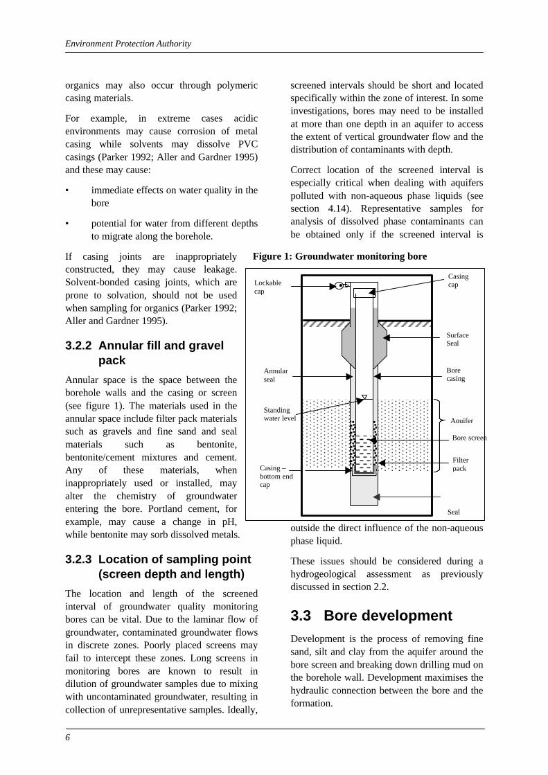
3.2.2 Annular fill and gravel pack
Annular space is the space between theborehole walls and the casing or screen(see figure 1). The materials used in theannular space include filter pack materialssuch as gravels and fine sand and sealmaterials such as bentonite,bentonite/cement mixtures and cement.Any of these materials, wheninappropriately used or installed, mayalter the chemistry of groundwaterentering the bore. Portland cement, forexample, may cause a change in pH,while bentonite may sorb dissolved metals.
3.2.3 Location of sampling point (screen depth and length)
The location and length of the screenedinterval of groundwater quality monitoringbores can be vital. Due to the laminar flow ofgroundwater, contaminated groundwater flowsin discrete zones. Poorly placed screens mayfail to intercept these zones. Long screens inmonitoring bores are known to result indilution of groundwater samples due to mixingwith uncontaminated groundwater, resulting incollection of unrepresentative samples. Ideally,
screened intervals should be short and locatedspecifically within the zone of interest. In someinvestigations, bores may need to be installedat more than one depth in an aquifer to accessthe extent of vertical groundwater flow and thedistribution of contaminants with depth.
Correct location of the screened interval isespecially critical when dealing with aquiferspolluted with non-aqueous phase liquids (seesection 4.14). Representative samples foranalysis of dissolved phase contaminants canbe obtained only if the screened interval is
outside the direct influence of the non-aqueousphase liquid.
These issues should be considered during ahydrogeological assessment as previouslydiscussed in section 2.2.
3.3 Bore developmentDevelopment is the process of removing finesand, silt and clay from the aquifer around thebore screen and breaking down drilling mud onthe borehole wall. Development maximises thehydraulic connection between the bore and theformation.
Seal
Lockablecap
Casingcap
SurfaceSeal
Borecasing
Annularseal
Standingwater level
Bore screen
FilterpackCasing –
bottom endcap
Aquifer
Figure 1: Groundwater monitoring bore

Groundwater Sampling Guidelines
7
Bore development generally involves activelyagitating the water column in a bore, thenpumping water out until it is visibly clean andof a constant quality. The development processfor monitoring bores should not introduce air,water or other materials into the aquifer.
In most formations, the application ofdevelopment techniques will result in ‘virtuallyparticulate free’ water returns from bores(ARMCANZ 1997). However, developmenttechniques are limited for small-diametermonitoring bores (typically of 50 mmdiameter) in low hydraulic conductivityaquifers. In such conditions, bore developmentmay not result in samples free of turbidity.Specific techniques may need to be employedto maximise the development process.
All bores used for groundwater qualitymonitoring should be developed after drilling,then left for a period until bore chemistry canbe demonstrated to have stabilised (anywherebetween 24 hours and seven days) beforesamples are collected. See section 4.5.1 forfurther information on stabilisation of borechemistry.
During development, bore yield should beestimated by monitoring the rate of recovery ofwater in the bore after pumping. Thisinformation can then be used to select suitablemethods for subsequent purging and sampling.
Key factors that can influence groundwatersamples (pre-sampling)
Objective
Groundwater monitoring bores should bedrilled, constructed and developed such thatthere is minimal impact on therepresentativeness of groundwater samples.
Key measures
• Drilling technique should minimisecompaction or smearing of boreholewalls and transport of geologicalformation materials into different zones.
• Drilling fluids used should cause minimalimpact on groundwater chemistry.
• Groundwater monitoring bores shouldbe constructed of materials that arecompatible with the groundwaterenvironment and will not leach or sorbcontaminants into groundwater samples.
• Groundwater monitoring bores shouldbe developed after drilling andconstruction and left for a period of timeuntil bore chemistry can bedemonstrated to have stabilised.
• Drilling method, drilling fluids used andbore development details should berecorded.
• Groundwater monitoring bores shouldbe assessed to ensure that they willenable sampling program objectives tobe met. This will require examination ofmonitoring bore drilling, construction,development and screen location detailsand a physical inspection of the bore toestablish its physical condition.
3.4 Further informationThe following documents provide a moredetailed discussion of the above issues:
1. Agriculture and Resource ManagementCouncil of Australia and New Zealand1997, Minimum ConstructionRequirements for Water Bores inAustralia.
2. Driscoll F.G. 1986, Groundwater andWells, 2nd Edition, Johnson Division,St. Paul, Minnesota.
3. EPA, EPA Publication 668,Hydrogeological Assessments(Groundwater Quality), EnvironmentProtection Authority (Victoria)(forthcoming).
4. Nielsen, D. M. 1991, PracticalHandbook of Groundwater Monitoring,Lewis Publishers, New York.
5. USEPA 1995, Groundwater Sampling –A Workshop Summary, EPA/600/R-94/205, Washington.

Environment Protection Authority
8
4. GROUNDWATER SAMPLING
4.1 Groundwater samplers
Groundwater sampling requires specialexpertise and should be undertaken by, or inconsultation with, appropriately qualified andexperienced personnel (eg hydrogeologists).This is especially critical in situations where asite is underlain by complex hydrogeology.
Consultation with a qualified analyst beforesampling is highly recommended, especiallywith respect to the preservation of samplesderived from anaerobic environments.
Groundwater samplers
Objective
To ensure that all actions taken duringgroundwater sampling will result in thecollection of groundwater samples that arerepresentative of groundwater in the aquifer.
Key measures
• Groundwater sampling should beundertaken by, or in consultation with,appropriately qualified and experiencedpersonnel.
• Consultation with a qualified analystbefore sampling is recommended.
4.2 Planning and preparation
Careful planning and preparation are essentialelements of groundwater sampling. This maysave time and reduce difficulties commonlyexperienced during fieldwork. It may alsoavoid the discovery of errors after samplinghas been completed.
Planning and preparation
Objective
To enable efficient and effective groundwatersampling by undertaking careful planning andpreparation.
Key measures
The following is a list of information thatshould be considered or determined beforecommencing groundwater sampling:
1. The objectives of the groundwatersampling and analysis program.
2. The site-specific parameters to besampled and analysed.
3. Number and frequency of samples to becollected.
4. Bore details, including location, depthand diameter of bore, depth and lengthof screened interval, depth togroundwater, bore drilling, installationand development details.
5. Sampling protocol, including purgingprocedure, in-field measurements,sampling technique and equipment,filtration and preservation requirementsand quality assurance/quality control(QA/QC).
6. Sample storage and transportation to thelaboratory.
7. Ensure that laboratories performinganalyses are accredited by the NationalAssociation of Testing Authorities(NATA) for all the tests conducted. Inaddition the laboratory should beexperienced and proficient at testing thetypes of samples, at the concentrationranges required, for the particularprogram.
8. Analytical methods and limits ofreporting for each method inconsultation with the laboratory analyst.
Groundwater Sampling Guidelines
9
9. Schedule samples for receipt bylaboratory. Discuss foreseeableproblems with procedures, containersetc. Collect sample bottles, trip blanks,preservatives and spike solutions asrequired.
10. Calibrate field meters (according tomanufacturers’ instructions) that don’tneed to be calibrated in the field andensure that all meters are workingcorrectly. Ensure correct calibrationsolutions are available.
11. Results from past sample eventsincluding groundwater levelmeasurements, field measurements andpurge volumes. These may be useful asa comparison and may be read in thefield if necessary.
It is useful to compare field results frompast sampling events while taking fieldreadings – if readings are greatlydifferent (eg two metre differencebetween groundwater levels) thenreadings should be retaken immediatelyto confirm correct reading. This willsave time and minimise the risk ofacquiring inaccurate data.
12. Sample documentation (eg QA/QCforms, checklists, chain-of-custodyrequirements).
13. The owner of the bore(s) should beinformed of proposed sampling insituations where they are not the clientor site owner.
Items 2, 4 and 11 should be detailed in ahydrogeological assessment (see EPAPublication 668, Hydrogeological Assessments(Groundwater Quality)).
4.3 Quality assurance andquality control (QA/QC)
Quality assurance and quality control ensurethat the quality of the data that is collectedduring groundwater sampling is reliable andconsistent with the objectives of its sampling
program. The quality of data required bysampling programs will vary depending on theobjectives of the program.
Groundwater sampling programs should aim togather information of a quality necessary tosupport decisions about the condition ofgroundwater at the site. The qualityrequirements may vary depending on thepurpose of the data and the decisions to bemade. For example in some cases a decisionmay depend simply on whether or not acontaminant is present, while in others it maydepend on the actual concentrations of thatcontaminant. In the latter case the qualityrequirements will be more stringent.
4.3.1 Quality assurance
Quality assurance (QA) is a critical componentof any sampling program and must be in placeand considered prior to sampling.
QA is ‘all the planned and systematic activitiesimplemented within the quality system anddemonstrated as needed, to provide adequateconfidence that an entity will fulfilrequirements for quality’ (StandardsAustralia/New Zealand, 1994). A qualitysystem is defined as ‘the organisationalstructure, procedures, process and resourcesneeded to implement quality management’(Standards Australia/New Zealand, 1994).
In terms of groundwater sampling QA involvesthe organisational procedures, processes,resources and review necessary to ensure thatthe results of the sampling program accuratelyreflect the state of the environment at the timeof sampling.
QA for groundwater sampling should considerthe following (note the overlap with section4.2, Planning and Preparation):
• objectives of sampling with regard todata quality (the level of uncertainty thatis acceptable)
• project responsibilities (who willperform each task)
Environment Protection Authority
10
• protocols to be used for groundwatersampling
• sample custody
• quality control samples (eg which ones,how many)
• the specific analytical methods for eachanalyte
• storage protocols/procedures andholding times
• sample container and preservativerequirements.
QA procedures and protocols do not have to becomplex. However, they should clearly statethe needs and requirements of the samplingprocess.
Additional information on QA is provided inappendix D of EPA Publication 441, A Guideto the Sampling and Analysis of Waters,Wastewaters, Soils and Wastes.
4.3.2 Quality control
QC provides critical aspects for the quality ofdata, fitting within the framework and systemprovided by QA. QC ‘involves operationaltechniques and activities aimed both atmonitoring a process and at eliminating causesof unsatisfactory performance at all stages ofthe quality loop’ (Standards Australia/NewZealand, 1994).
QC involves specific activities to assure thequality of samples, including the collection ofinformation that identifies any errors due topossible sources of cross contamination andinconsistencies in sampling, and provideschecks on the analytical techniques used. Thereliability of data cannot be assured withoutthe information QC provides.
For example, QA procedures and protocolsmay require various QC activities such asdecontamination of sampling equipmentbetween sampling points to ensure that cross-contamination is avoided and the collection ofrinsate blanks to ensure that the
decontamination process has been successfuland no cross contamination has occurred.
QC in groundwater sampling includes thecollection of QC samples (duplicates andblanks), such as:
BlanksA blank is a portion of deionised water that iscarried through all or part of the samplingprocess. The volume used for the blank shouldbe the same as for the samples.
Various blanks may be collected:
Trip blanks: These are used to monitorpotential contamination during transport andstorage. Trip blanks are sent from thelaboratory with empty containers and remainwith the other samples throughout sampling.
Field blanks: These are used to monitorcontamination during sampling. These blanksare taken under field conditions duringsampling and should include any filtration oraddition of preservatives as appropriate.
Rinsate blanks: A rinsate blank is generallytaken from the final rinse of equipment afterdecontamination. These samples provideinformation ensuring that there is no cross-contamination of samples from the samplingequipment.
DuplicatesDuplicates are samples taken in immediatesuccession and subjected to the same filtering,preservation, holding and analysis methods.Duplicates are taken as a check for precision(repeatability) of sample analysis.
The number of sets of duplicate samplesrequired should be commensurate with therequired quality of the data (or the limits forthe overall uncertainty of results) for decisionmaking purposes.
Duplicates may either be submitted to the samelaboratory, as blind replicates, without anyindication that they are duplicates or they maybe sent to a second laboratory, as split samples,
Groundwater Sampling Guidelines
11
to provide a further check on the accuracy oflaboratory analysis.
Duplicate samples may be compared asrelative percent difference (RPD).
RPD = Result 1 – Result 2
x 100Mean of result 1&2
Depending on the analytes and theirconcentrations, varying RPDs may beacceptable.
Quality assurance and quality control
Objective
To ensure groundwater sampling is undertakenin accordance with appropriate QA/QC.
Key measures
A QA program should be in place. This shouldconsider:
• objectives of sampling with regard todata quality
• project responsibilities
• protocols to be used for groundwatersampling
• sample filtration/preservation
• sample custody
• quality control samples
• specific analytical methods for eachanalyte
• storage requirements and holding times
• sample preservative requirements.
4.4 Groundwater level measurements
Groundwater level measurements are essentialto determine groundwater and contaminantflow directions and rates within aquifers.These measurements can provide informationon lateral and vertical head distribution andhydraulic gradients within individual aquifersand between aquifers in layered aquifer
systems. Long-term groundwater monitoringprograms provide information on the temporaltrends in groundwater levels (and thereforeflow directions and rates) due to the effects ofdrought, high rainfall events and groundwaterpumping.
Some important factors to be considered whenplanning the collection of groundwater datainclude:
• Groundwater levels should always bemeasured and recorded on the same day(along with the date and time), to acommon datum (generally mAHD –Australian Height Datum), beforedisturbance of bore water.
• Groundwater levels in new bores maytake some time to stabilise afterinstallation and development (in lowpermeability formations this may requireseveral days or longer).
• In some environments irrigation,pumping or tidal influences may causerapid groundwater level fluctuations andfrequent (hourly) measurement may berequired.
• In some situations, water canaccumulate in bores. Takinggroundwater level measurements afterpurging, as well as before anydisturbance of bore water, may provideresults that are more representative ofaquifer conditions.
• Methods and instruments used to collectand record changes in groundwaterlevels can vary substantially dependingon the design of the monitoring programand borehole construction. The morecommon instruments are fox whistles,electrical tapes, pressure transducers andmanometers or pressure gauges forflowing bores. Although manyelectronic methods exist, such aspressure transducers and data loggers,fox whistles remain both accurate andreliable.

Environment Protection Authority
12
Groundwater level measurements
Objective
To obtain accurate and representativemeasurement of groundwater level.
Key measures
• Before groundwater level is measured itshould be allowed to stabilise after boreinstallation and development.
• Groundwater level should be measuredbefore disturbance of bore water (ie dueto sampling).
• Groundwater level should be measuredto a common datum.
• All groundwater levels at a site shouldbe measured and recorded on the sameday.
• Where there are rapid fluctuations ingroundwater level more frequent(hourly) measurements should be taken.
4.5 PurgingIn most groundwater monitoring bores, there isa column of stagnant water above the borescreen that remains standing in the borebetween sampling rounds. Stagnant water isgenerally not representative of formation waterbecause it is in contact with bore constructionmaterials (eg casing) for extended periods, is indirect contact with the atmosphere and issubject to different chemical equilibria.Stagnant water often has different temperature,pH, redox potential, dissolved oxygen and totaldissolved solids content from formation water.Volatile organic compounds and dissolvedgases in stagnant water may volatilise oreffervesce within as few as two hours (Nielsen1991).
Purging is the process of removing stagnantwater from a bore before sampling. Purgingaims to enable the extraction of a sample thatis representative of formation water whilecreating minimal disturbance to thegroundwater flow regime. Although purging isnecessary in most situations, purging itself
may affect the chemical composition andhence representativeness of samples.
There are a number of different approaches toensuring that formation water rather thanstagnant water is sampled. These approachesare used in different situations and should beconsidered on a case-by-case basis, dependingon aquifer parameters and analytes of concern.Methods include:
• removal of a number of bore volumes ofgroundwater until chemical equilibriumis reached
• low-flow purging until chemicalequilibrium is reached
• passive sampling where minimalpurging is required.
In all cases bores should be purged andsampled in order of least (or least likely) tomost (or most likely) contaminated.
4.5.1 Removal of a number of bore volumes until chemical equilibrium is reached
Using this purging method, bores should bepurged until all stagnant water is removed andwater within the bore is representative offormation water. The rate of purging must beless than the rate of pumping during boredevelopment.
Measuring stabilisation criteria such as pH,dissolved oxygen, electrical conductivity,redox potential (Eh) and turbidity candetermine when stagnant water has beenpurged (Puls and Powell 1992; Puls andPowell 1997). Where possible, theseparameters should be measured using a flow-through cell.
The parameters may be considered stable whenthree consecutive readings (obtained severalminutes apart) are within:
• ± 10% for dissolved oxygen• ± 10% turbidity
• ± 3% for electrical conductivity (specificconductance)

Groundwater Sampling Guidelines
13
• ± 0.05 for pH
• ± 10mv for redox potential.
(Puls 1995; Nielsen 1991)
The most sensitive of these parameters areredox potential, dissolved oxygen and turbidity(Puls et al. 1992).
A number of bore volumes (commonly 3–5bore volumes) may need to be removed from abore before drawn water is representative offormation water. The bore volume should becalculated to include the screened interval. Thebore volume may be calculated by using thefollowing equation:
Bore Volume = casing volume + filter pack
volume= πh1d2
2/4 + n(πh1d12/4-πh2d2
2/4)
Where: π = 3.14
n = porosity (0.3 for most filter pack
material)
h1 = height of water columnd1= diameter of annulus
h2 = length of filter packd2 = diameter of casing
The default removal of a set number of borevolumes (ie 3–5) without measurement ofstabilisation criteria does not ensurerepresentative samples and should not be usedas purging method. In some situations, 10 oreven 20 bore volumes may need to be removedbefore parameters stabilise (Nielsen 1991,p.465). The time or purge volume required forparameter stabilisation is independent of boredepth and volumes (Puls and Barcelona 1996).
Pumping or bailing large volumes ofgroundwater may lead to:
• sampling water which may be at a depthother that that at which the bore isscreened; or
• the introduction of groundwater somedistance from the bore that may dilute orconcentrate some sampling parameters.
This can lead to order of magnitude errors indissolved chemical constituent data(Barcelona, Wehrmann and Varljen 1994).Over-pumping may cause high turbidity anderroneously high measurements of total metalslevels as well as the potential for damage to thefilter pack (Barcelona, Wehrmann and Varljen1994).
At contaminated sites, treatment and disposalof contaminated groundwater removed duringpurging and sampling require care to avoidoccupational health and safety risks orpollution of surface water, land oruncontaminated groundwater.
4.5.2 Low flow purging until chemical equilibrium is reached
Purging large volumes of water can beimpractical, hazardous or may adversely affectthe contaminant distribution in the sub-surface(eg through dilution). Low-flow purging (ormicro-purging) involves minimal disturbanceof the water column and aquifer and ispreferable to the removal of a number of borevolumes. This method removes only smallvolumes of water, typically at rates of 0.1 to0.5 L/min (Puls and Powell 1997), at a discretedepth within the bore.
Low-flow purging relies on the concept thatgroundwater moves horizontally through thescreened interval in a bore and that formationwater does not mix with the stagnant waterabove the screened interval (see figure 2).
Low-flow purging consists essentially of thefollowing steps:
• The pump inlet is carefully and slowlyplaced in the middle or slightly abovethe middle of the screened interval at thepoint where the contaminantconcentration is required (dedicatedpumps are ideal for low-flow sampling).Placement of the pump inlet too close tothe bottom of the bore can causeincreased entrainment of solids, whichhave collected in the bore over time.

Environment Protection Authority
14
• Purging begins, typically at a rate of 0.1to 0.5 L/min, although higher rates maybe possible providing the rate of purgingdoes not cause significant draw down inthe bore.
• During purging, groundwaterstabilisation parameters should bemeasured and recorded as per Section4.5 to determine when they stabilise.
• When parameters have stabilised thesample may be collected, at a rateslower or equal to purge rate.
4.5.3 Passive sampling
Passive sampling is the process of acquiring asample from a bore without disturbing thestagnant water within the bore. A pump ispermanently installed in the bore, the intakeplaced within the screened interval and left fora sufficient period of time until water inscreened interval has reached chemicalequilibrium. During sampling no agitation ofthe water column occurs as the sample devicedoes not need to be inserted into the bore (seefigure 2). It is therefore possible to generatevery low purge volumes (less than 1 bore
volume according to Barcelona, Wehrmannand Varljen 1994) by pumping at a low-flowrate as the only purging required is forevacuation of the sampling device (pumpbody, tubing, etc).
As passive sampling relies on the sample/purgedevice not agitating the water column, inertialsamplers and bailers cannot be used duringpassive sampling. It is not always necessary tomeasure stabilisation parameters duringpurging for passive sampling. However, it isadvisable to measure these parameters the firstfew times a bore is sampled to enable a purgevolume to be established.
Passive sampling techniques have the potentialto provide the best contaminant concentrationdata (Puls and Powell 1997).
4.5.4 Low hydraulic conductivity aquifers
In some low hydraulic conductivity formationsit may not be possible or practical to pumpbores until field parameters stabilise, as borerecovery is slower than pump rates, includinglow-flow pump rates. Low hydraulicconductivity formations are generally fine
Aquifer
Direction ofgroundwater throughscreened interval
Water above screened intervaldoes not mix with water withinscreened interval
Screenedinterval
Filterpack
Groundwater flows horizontallythrough the screened interval
Disruption caused by insertion ofsampling device
modified from Puls and Powell 1997
Figure 2: Groundwater flow through a bore

Groundwater Sampling Guidelines
15
grained (eg clay) and are naturally moresusceptible to producing turbid water samples.
The recommended procedures for purging lowhydraulic conductivity bores are:
1. Use of low-flow purging (ideally,passive sampling) as discussed insections 4.5.2 and 4.5.3. Purging at lessthan 0.1 L/minute may be required.Packers may be useful to isolate thesection being sampled.
2. Where significant drawdown in the bore isunavoidable the screened interval shouldnot be dewatered. This may requirerepeated recovery of bore water duringpurging while leaving the pump in placewithin the screened interval of the bore.
Purging the bore dry is not recommended asthis may expose the sample to air and othergases or floating substances, producing anunrepresentative sample.
Purging
Objectives
To ensure that formation water is sampledrather than stagnant water.
Key measures
• In all cases bores should be purged andsampled in order of least (or least likely)to most (or most likely) contaminated.
• Field parameters (eg pH, specificconductance, dissolved oxygen, redoxpotential, temperature and turbidity)should be allowed to stabilise beforesamples are taken.
• Field measurements of stabilisationcriteria should be recorded.
• Bailers and inertial samplers should notbe used for low-flow purging as they cancause repeated disturbance and mixingof bore water.
• Use consistent purging and samplingmethods over time from the same bore.
• The screened interval in the bore shouldnot be dewatered.
• The rate of purging must be less than therate of pumping during development.
• Purging method used should be recorded.
4.6 Field measurementsField measurement of groundwater parametersprovides a rapid means of assessing certainaspects of water quality. It has the advantageof reducing the possibility of contamination orchange in sample composition betweencollection and analysis.
Field measurements are generally taken to:
• Ensure that formation water is beingsampled.
• Provide on-site measurements for waterquality parameters that are sensitive tosampling and may change rapidly (egtemperature, pH, redox and DO).Careful field measurement enablesrepresentative analysis.
• Compare with laboratory measurementsof these parameters to assist in theinterpretation of analytical results ofother parameters (eg check for chemicalchanges due to holding time,preservation and transport).
Groundwater parameters measured in the fieldmust include pH, temperature, dissolvedoxygen, redox potential and conductivity andmay include turbidity. Some ions, such asfluoride and sulfide, can also be determinedusing ion selective electrodes, although theirdetermination can be subject to matrixinterferences.
Field measurements may be taken either in situor after groundwater has been extracted from abore. If groundwater is being pumped, it isrecommended that a flow-through cell withprobes be used for field measurements, as itallows for continuous measurement andminimises sample contact with the atmosphere.
Field measurements should be takenimmediately before collecting each sample.
Ensure field instruments are robust and reliableand that they are capable of measuring to theappropriate level of accuracy. They must becalibrated before use with fresh solutions. pHand dissolved oxygen meters need to becalibrated before every use. Calibration can be

Environment Protection Authority
16
performed either in the laboratory or in thefield. The manufacturer’s instructions are thebest guide for the use of any particular meter.However, meters must be calibrated accordingto the NATA publications, GeneralRequirements for Registration: SupplementaryRequirements: Chemical Testing (NATA1993) and Technical Note No. 19 (NATA1994).
The meter must be calibrated over anappropriate range for the samples analysed. Ifthe meter is to be used over several hours,periodic readings of a reference solution mustbe made to ensure the calibration is stable. Ifexcessive drift is observed, readings taken overthe period of drift must be discarded.
While field meters are designed to withstand alevel of harsh treatment (such as knocks,vibration and extreme temperature changes),good maintenance and calibration regimesensure that meters produce reliable andaccurate data.
Secondary parameters such as temperature,salinity, altitude and air pressure may affectsome field measurements. For example, all ofthe above parameters affect dissolved oxygenreadings. If the field meter does notautomatically measure and compensate for asecondary parameter, then this parameter mustbe measured using the appropriate equipmentand a manual compensation performed. Themanufacturer’s instructions should beconsulted for correction factors.
Many factors may cause interference whentaking field measurements. These interferencescannot be compensated for. In particular, oilyfilms, high levels of suspended solids andelectrical fields may cause problems. If themeasurements are being taken in unusualsituations, the field conditions should berecorded and the manufacturer’s instructionsshould be consulted to establish whetherinterference could occur.
Field measurements
Objective
To ensure accurate measurement of waterquality parameters using field meters.
Key measures
• Field measurements should be takenimmediately before collecting eachsample.
• Where groundwater is pumped a flow-through cell should be used to take fieldmeasurements.
• Field meters must be calibratedaccording to manufacturer’s instructionsand according to the NATApublications, General Requirements forRegistration: SupplementaryRequirements: Chemical Testing(NATA 1993) and Technical Note No.19 (NATA 1994).
• If field meters are to be used overseveral hours, periodic readings of areference solution must be made toensure calibration is stable.
Potential causes of interference in the fieldmust be recorded.
4.7 Sample collectionGroundwater samples should be collectedwhen the solution chemistry of thegroundwater removed from a bore hasstabilised as indicated by pH, DO, redox, EC,temperature and turbidity readings (see section4.5.1). Where a flow-through cell is used tomonitor water quality parameters, it should bedisconnected or bypassed during samplecollection as solutions in the probes can affectsample chemistry.
Samples should be collected at a rate slower orequal to the purging rate. Where samples arecollected at a faster rate than purging, particlespreviously not removed during purging may beforced out of the aquifer/gravel pack and intothe sample.
The same device should be used for samplingas previously used for purging.

Groundwater Sampling Guidelines
17
4.7.1 Processes responsible for altering sample chemistry
The major processes involved in altering thechemistry of samples and which may bedirectly controlled by choice of samplingdevice are volatilisation, degassing, oxidation,precipitation and sorption.
Volatilisation is the loss of dissolvedcompounds by evaporation upon contact with agas phase and is controlled by the vapourpressure of the solute or solvent. Compoundsmost susceptible to volatilisation includevolatile organic compounds such aschlorinated hydrocarbons (eg TCE) andmonocyclic aromatic hydrocarbons (egbenzene).
Degassing is the loss of dissolved gas fromsolution and can result from either an increasein temperature or a decrease in pressure.Parameters potentially affected by degassingare pH (likely to increase through loss ofcarbon dioxide) and pH-sensitive parameterssuch as heavy metals, alkalinity andammonium (all likely to decrease). Totaldissolved solids and total organic carbon arealso affected and are likely to decrease inconcentration due to degassing.
Precipitation is the formation of solids fromconstituents that were once dissolved.Precipitation can be caused by a change inconditions, such as temperature, pH, chemicalconcentration, or the presence of seed particlesto begin the process. For example, where agroundwater sample experiences loss of carbondioxide, a rapid change in pH can occur,causing precipitation of metals such as iron.
Oxidation is caused by the introduction ofoxygen (in air) to the sample. Oxidation resultsin increased dissolved oxygen, pH and redox.These changes can potentially lead todecreases in concentrations of calcium ions,magnesium ions, heavy metals (particularlyiron and manganese), hydrogen sulphide andammonium. Oxidation could also cause adecrease in the concentrations of bulk organicparameters, chemical oxygen demand,biological oxygen demand and total organic
carbon, due to accelerated oxidation of organicconstituents such as volatile fatty acids andsemi-volatile organic carbon.
Sorption involves the attraction of dissolvedconstituents to the surface of solid particles.Any process or activity that increasessuspended solids in samples can change themeasured concentrations of dissolved majorions, heavy metals and hydrophobic organiccompounds (eg organochlorinated pesticides).A loss of dissolved constituents from samplesdue to sorption can result where the dissolvedconstituents sorb onto solids in suspensionbefore the solids are separated from the samplefor laboratory analysis. Alternatively, whereadditional solids/colloids remain in solution orsuspension (ie turbid samples) during analysis,increased concentrations of ions and metalsmay be recorded. The presence of fine grainedmaterials combined with low redox potentialconditions may promote increased turbidity bythe formation of colloids (Saar 1997).
4.7.2 Sampling deviceAccording to Barcelona (1995), field sampling(of groundwater) can often be the mostsignificant source of error in determininganalytical results that are representative of fieldconditions. Error introduced during sampling isa significant issue. While very low detectionlimits are possible in the laboratory, they maybe limited by practical considerations related tothe performance of sampling devices in thefield.
An appropriate device should be selected forcollection of groundwater samples. To do so,the following issues need to be considered andwill directly affect the quality of groundwatersamples collected (these issues are alsorelevant to choice of purging device):
1. The sampling device should causeminimal physical or chemical alterationto the sample. As discussed in section4.7.1, it is important that the samplingdevice does not cause degassing,aeration, volatilisation, oxidation,sorption or precipitation through:

Environment Protection Authority
18
• the mode of transporting the sampleto the surface
• interaction with the materials ofconstruction of the device, or
• transfer of the sample to itscontainer.
To gain the most representative data it isrecommended sampling devices beconstructed from inert materials such asstainless steel and Teflon. Flexiblecomponents such as tubing should compriseflexible PVC or polyethylene. However, thematerials selected will depend on thesensitivity of the information required.
Appendices A and B provide informationon sampling devices in relation to theiradequacy for contaminants of concern andtheir potential impacts on sample quality.
• The possibility of using a dedicatedsampling device permanently installedin the bore should be considered. Thisapproach can reduce time (and cost)involved in set-up, sampling anddecontamination procedures. Adedicated pump also enables passivesampling techniques to be employed,allowing collection of morerepresentative groundwater samples.
• Ideally, it should be possible to use thesame sampling device for sampling andfor purging to reduce the amount ofdecontamination required and to reduceturbulence in the bore.
• Where a bailer is used, use cord that canbe decontaminated between each bore.Cotton or cloth cord should not be used.
The following issues are important practicalconsiderations that need to be addressed beforesampling:
1. The depth from which the sample iscollected is important, as the deeper thesample interval the more head the devicemust overcome to deliver the sample tothe surface.
2. The bore must be able to accommodatethe sampling device. The smaller thediameter of the bore, the more limitedthe options.
3. Ease of operation, cleaning andmaintenance.
4. Ease of repair – it is a distinct advantageto be able to repair the device in thefield.
5. Reliability and durability – especiallywhere the sampling device is to be usedfor an extended period in groundwaterenvironments containing chemicalconstituents that cause corrosion ofmetallic parts or degradation of syntheticmaterials.
The sampling device selected should beassessed for its impact on results and thesampling technique used should becommensurate with the required sensitivity oruse of the data. In general, bladder pumps arelikely to cause minimal disturbance to samplesduring collection. They are generally the mosteffective sampling devices for sampling gas-sensitive analytes and VOCs (Parker 1994;Barcelona et al. 1984).
4.7.3 Diffusion samplers for volatile organic compounds(VOCs)
Diffusion samplers are an alternative methodfor sampling VOCs. Diffusion samplers consistof distilled water enclosed by a polyethylenemembrane. The membrane allows diffusion ofVOCs from aquifer water into the distilledwater until equilibrium is reached (Vrobleskyand Hyde 1997). The process involves:
1. placing diffusion sampler at screenedinterval in bore
2. leaving diffusion sampler within borefor approximately two weeks, untilequilibrium is reached and the samplercan be removed.

Groundwater Sampling Guidelines
19
The advantages of this method overconventional purging/sample collection(bailing in particular) are:
• no purging required
• minimum disturbance of sample leadingto minimal loss of volatile contaminants
• diffusion sampler can be accuratelyplaced so that sample is taken from thescreened interval.
Sample collection
Objective
To minimise impact on representativeness ofgroundwater sample due to sample collection.
Key measures
• Groundwater samples should becollected when the solution chemistry ofthe groundwater removed from a borehas stabilised.
• Disconnect or bypass flow-through cellbefore collecting sample.
• Samples should be collected at a rateslower or equal to the purging rate.
• The same device should be used forsampling as previously used for purging.
• Sampling device should cause minimalphysical or chemical alteration to thesample.
4.8 Filtration of groundwater samples
Filtration is the process of separatingsuspended solids from a sample by forcing itthrough a porous barrier (filter). Filtration isundertaken to enable samples to be preserved(eg addition of concentrated acid to samplesfor metals analysis) as soon as possible aftersampling without suspended solids adverselyinfluencing the representativeness of thesample. As with other components ofsampling, filtration is known to significantlyaffect the resultant analytical data. Thus, the
need for filtration must be thoroughlyconsidered before (and during) sampling.
4.8.1 Is filtration necessary?
The objectives of sampling need to beconsidered in determining the need forfiltration. Ideally, samples should be collectedso that there is no need to filter. The purgingand sampling techniques used should minimisedisturbance and agitation and thereforeintroduce little suspended solids to the sample.
Even when suitable purging and samplingtechniques are used, filtration of groundwatersamples may be necessary when:
• sampling to determine truly dissolvedconcentrations of analytes; or
• it is not possible or practical to obtain asample with low turbidity (ie visuallyclear) due to solids suspended as a resultof purging and sampling, and
• sampling to determine mobileconcentrations of analytes (dissolvedand colloidal) subject to sorption bysuspended particles (predominantlymetals and hydrophobic contaminantssuch as PCBs and organochlorinepesticides).
The decision to filter or not to filtergroundwater samples must be reported withresultant analytical data. Spatial and temporalconsistency in methodology are important toensure comparability of groundwater qualitydata.
4.8.2 Purging and sampling technique
Purging and sampling methodology can have alarge impact on whether a sample needs to befiltered. Techniques that cause agitation ofwater in a bore (eg inertial lift pumps andbailers) are more likely to produce samplesthat are highly turbid. Increased pump rates(greater than 1 L/min) increase sampleturbidity and bring larger particles intosuspension (Puls et al. 1992). Samplesobtained by low flow or passive sampling are

Environment Protection Authority
20
more likely to be low in turbidity. In situationsin which a bore may produce turbid samples,techniques should be used that obtain the leastturbid, and subsequently the mostrepresentative, samples of groundwater.
Filtration should be avoided where it isreasonably possible to change samplingpractice to eliminate turbidity caused bypurging and sampling. Filtration should not beused to compensate for inadequate samplingpractice (Barcelona et al. 1995).
4.8.3 Effects of sample filtration
Some effects that filtration may have on asample are described below:
• The exposure of sample to air duringfiltration can cause metals such as ironto oxidise and precipitate. The ironprecipitates may clog the filter, therebyfurther lowering the iron concentrationin the sample. Iron precipitates may alsoentrain other metals (through co-precipitation) resulting in furtherreduced metal concentrations in thesample.
• Adsorption of dissolved metals in thesample onto the filter material.
• Clogging of filter pores by suspendedsolids.
• Removal of small suspended solids thatare naturally mobile in groundwater.
• Increased sample handling.
Adverse effects of filtration on the sample maybe minimised in the following ways:
• Exposure of the sample to air can beavoided by using an in-line filtrationapparatus.
• Adsorption of metals may be reduced byrinsing the equipment with sample waterbefore sample collection.
• Pore clogging may be reduced byincreasing the ratio of filter surface areato volume of water filtered by:
– changing the filter regularly
– increasing the filter diameter
– using filter cartridges, which havemuch greater surface area
– processing the minimum amount ofwater needed for analysis.
4.8.4 When sample filtration is necessary
Where filtration is necessary, it should occur inthe field, immediately after each sample hasbeen collected and before chemicalpreservation.
The mechanism for filtration may be eitherthrough gravity or applying vacuum or pumppressure. In all cases, only low pressuresshould be applied.
Direct, in-line filtering of samples isrecommended. Direct, in-line filtration occursby attaching the filter directly to a pump’sdischarge line or to the discharge tube of agrab sampler (eg bailer).
Careful consideration of an appropriate porediameter is necessary before filtering. Themost common size of filter used in collectionof groundwater samples is 0.45µm. The use ofthis filter diameter does not achieve anaccurate representation of:
• truly dissolved metal concentrations –0.1µm or 0.05µm may be moreappropriate (Puls and Barcelona 1989)
• concentrations of contaminants that aresorbed to colloids larger than 0.45µmthat are naturally mobile in groundwater(Saar 1997)
A wide range of filtration media exists. Theseinclude cellulose nitrate, cellulose acetate andglass fibre filters. Cellulose nitrate filters arecommonly used for major ions (excludingnitrates) and metals, while cellulose acetate isused for nutrients (including nitrates). Glassfibres are sometimes used as they block lessfrequently, however, they do not have a well-defined pore size (Murray-Darling BasinCommission 1997).
Groundwater Sampling Guidelines
21
Filtering devices should be cleaned in a similarmanner to sample containers and care taken toensure that contamination is not introduced inthe field. Filters from the same batch used inthe field and the filtering device itself shouldbe provided to the laboratory so that blanklevels can be determined. On-site (betweensample) final rinses from filtration equipmentshould also be submitted to the laboratory as‘rinsate blanks’ for analysis.
4.8.5 Where filtration is necessary but cannot be undertaken in the field
Where field filtration is necessary but isexpected to affect the representativeness ofsamples due to extreme field conditions, ormay pose an unacceptable health or safety riskto field personnel, it may be necessary toundertake filtration in the laboratory. In suchsituations it will be necessary to:
• overfill and immediately seal samplecontainers
• cool the sample
• transport the sample to the laboratorywith minimum delay
• inform the laboratory of the need tofilter immediately on receipt of thesample and
• filter in the laboratory.
An analyst should be consulted wherepreservation is delayed due to not filtering inthe field.
Filtration of groundwater samples
Objectives
To enable samples to be preserved as soon aspossible after sampling without suspendedsolids adversely influencing therepresentativeness of the sample.
Key measures
• Filtration should be undertaken wherethe objective of sampling is to determinetruly dissolved concentrations ofanalytes.
• Filtration should be avoided where it isreasonably possible to change samplingpractice to eliminate turbidity caused bypurging/sampling and sampling todetermine mobile concentrations ofanalytes.
• Filtration should not be used tocompensate for inadequate samplingpractice.
• Where filtration is necessary, it shouldoccur in the field, immediately aftereach sample has been collected andbefore chemical preservation. In linefiltration is recommended.
• The decision to filter or not to filtergroundwater samples must be reportedwith resultant analytical data.
4.9 Sample containers, preservation, labellingand logging, transportand holding times
Decisions concerning the selection of samplecontainers, preservation procedures, labellingand logging, transportation and holding timesshould be made during the planning phase ofany sampling program. Sample preservation,containers and holding periods forgroundwater samples should be in accordancewith EPA Publication 441, A Guide to theSampling and Analysis of Waters,Wastewaters, Soils and Wastes.

Environment Protection Authority
22
4.10 DecontaminationAll equipment that either enters the bore orcarries the water from the bore to the samplingcontainer should be decontaminated beforeeach sample is taken. Decontamination ensuresthat sampling equipment is clean and containsno trace of the previously sampledgroundwater, which can cause erroneousanalytical results (cross-contamination).
Decontamination procedures should bedeveloped on a site-specific basis, consideringthe objectives of the sampling program,potential contaminants, and sampling andpurging equipment.
In general, decontamination proceduresinclude the following steps:
• Sampling and purging equipment shouldbe decontaminated away from thesampling location to minimise thepotential for cross-contamination.
• Decontamination solution to be usedmay be phosphate-free detergent, bleachor solvent. The cleaning solution willdepend on the contaminants beinginvestigated. For example, whensampling for microbiologicalparameters, bleach should be used tosterilise equipment between samplepoints. However, bleach would not beused if sampling for chlorine.
• Contaminant-free water (eg tap water)followed by distilled or deionised water(final rinse) should be used to wash andrinse equipment.
• In some cases (eg when investigating thepresence of organic contaminants) itmay be necessary to rinse equipmentwith solvent (eg acetone).
• Final rinsate (QC) samples should betaken from equipment as blanks toensure that all contamination has beenremoved.
• Equipment should be air dried beforeuse for sampling. Care should be takento ensure that exhaust, from motorvehicles or compressors, does notcontaminate equipment.
Provision should be made for disposal ofcontaminated wastewater or solvent from thedecontamination process. It may requirecontainment and disposal at an appropriatedisposal or treatment facility.
Decontamination
Objective
To avoid cross-contamination of groundwatersamples.
Key measures
• Decontaminate all groundwatersampling equipment between samplinglocations.
• Decontaminate equipment away fromthe sampling location.
• Contaminant-free water followed bydistilled or deionised water should beused to wash and rinse equipment.
• Final rinsate (QC) samples should betaken from equipment as blanks toensure that all contamination has beenremoved.
• Equipment should be air dried beforeuse for sampling.
4.11 Health and safetyFor information on health and safetyprecautions and warnings that must beobserved during sampling refer to EPAPublication 441, A Guide to the Sampling andAnalysis of Waters, Wastewaters, Soils andWastes.
4.12 DocumentationWhen conducting long-term monitoringprograms it is essential that samples becollected in a consistent manner so that theresultant analytical data is comparable. For thisto be possible, it is essential that groundwater

Groundwater Sampling Guidelines
23
sampling methodology be thoroughlydocumented on each sampling occasion.
Documentation
Objective
Documentation of sufficient data duringsampling to ensure that sampling practice isconsistent during each subsequent samplingoccasion.
Key measures
The following items should be recorded in alogbook or sampling work plan:
• purpose of sampling
• location, description and photographs ofsampling point
• detail of sampling site (elevation ofcasing, casing diameter, integrity ofcasing, casing depth, interval sampled,condition of bore)
• weather conditions during andimmediately preceding sampling (eg hasit rained in the preceding days?)
• reference to procedures for preparationof reagents or supplies that become anintegral part of the sample (eg filters andabsorbing reagents)
• identification of sampling team
• decontamination procedures
• sample method (including purging)
• standing water level
• pump rate for purging and sampling
• purged volume
• field measurements
• potential for interference with fieldmeasurements
• date and time of sample collection
• number and volume of samples taken(including any QC samples)
• field observations
• signature and date, by the responsiblepersonnel
• sample preservation including storagemethod
• sample transportation
• specific comments and remarks.
4.13 Reportinggroundwatersampling results
Overall, the groundwater sampling reportshould fully describe sampling methodologyand state any possible impacts samplingmethodology may have had on the quality ofthe sample.
Analysis and interpretation of analytical datashould be undertaken by appropriatelyqualified and experienced professionals (eghydrogeologists). Guidance on datapresentation is provided in EPA Publication668, Hydrogeological Assessments(Groundwater Quality).
Reporting groundwater sampling results
Objective
Accurate and consistent reporting ofgroundwater sampling details that assist ininterpretation of analytical results.
Key measures
Analytical results of groundwater samplingshould be presented along with the followinginformation:
• bore drilling, construction anddevelopment details
• purging and sampling equipment used
• purge technique (including volumesremoved and stabilisation criteria)
• visual observations of the sample
• field measurements
• whether samples were filtered orunfiltered
• whether samples were filtered in thefield or in the laboratory
• preservation techniques

Environment Protection Authority
24
• transport and holding times
• equipment decontamination details
• Quality Control sample results andinterpretation
• analytical results.
4.14 Sampling for non-aqueous phase liquids (NAPL)
Non-aqueous phase liquids (NAPLs) areorganic fluids that are immiscible (do not mix)with water. NAPLs may be lighter (LNAPL) ordenser (DNAPL) than groundwater, formingdiscrete layers or pools within the ground (eglayer of petrol situated on the water-table).When present in aquifers, NAPLs areconsidered to be an uncontrolled source ofgroundwater contamination that requireinvestigation and in most cases clean up. Thepresence of NAPLs can be significant forgroundwater sampling. Where light non-aqueous phase liquid is present within a bore,it is not possible to obtain a representativesample of groundwater for dissolved phasepetroleum components.
Sampling of NAPLs is a specialised subjectand a detailed methodology is beyond thescope of these guidelines. However, here aresome of the issues that that should beconsidered before sampling NAPLs:
• When investigating LNAPLcontamination, monitoring bores mustbe constructed so that the screenedinterval intersects the top of the watertable above which the LNAPL is mostlikely to be encountered.
• When investigating DNAPLcontamination, monitoring bores mustbe constructed so that the screenedinterval intersects the base of the aquiferor a low permeability layer, where theDNAPL may be encountered.
• DNAPLs may migrate in a differentdirection to that of groundwater flow.This will affect positioning of bores.
The following should be considered during thesampling of NAPLs:
• Sample at the interval where the NAPLis most likely to be encountered (ie thetop of the water column in a bore whensampling LNAPL or the bottom of thebore when sampling DNAPL).
• Do not purge before measuring thethickness of or sampling from the NAPLlayer.
• Measure LNAPL thickness with either aLNAPL/water interface probe or aweighted tape coated with a water andLNAPL sensitive substance todistinguish between the air/LNAPL andLNAPL/water interfaces.
• Measure DNAPL thickness with aninterface probe.
• Equipment decontamination may be quitedifficult therefore use of disposableequipment should be considered.
• Single or double check valve bailersmay be used for LNAPL collection,while double check valve bailers may beused for DNAPL collection. Peristalticpumps may also be effective.
Further information on sampling NAPLs iscontained in specialist texts such as:
• American Petroleum Institute 1996, AGuide to the Assessment andRemediation of Underground PetroleumReleases, Publication 1628, ThirdEdition, Washington.
• Canadian Council of Ministers of theEnvironment 1994, SubsurfaceAssessment Handbook for ContaminatedSites, Report CCME EPC–NCSRP–48E.
• Fetter, C. W. 1993, ContaminantHydrogeology, MacMillan PublishingCompany, New York.
• Pankow, J.F. and Cherry, J. A. 1996,Dense Chlorinated Solvents and OtherDNAPLs in Groundwater: History,Behaviour and Remediation, WaterlooPress, Guelph, Ontario.

Groundwater Sampling Guidelines
25
GLOSSARY
Annular space/Annulus The space between a bore casing and a borehole wall.
Aquifer A geological structure or formation, or part thereof, permeated withwater or capable of
(a) being permeated permanently or intermittently with water;
and
(b) transmitting water.
Bailer A bailer is a hollow tube with a check valve at the base (open bailer) or adouble valve (point source bailer) – used to remove water from a bore.
Bentonite A hydrous aluminium silicate clay mineral available in powdered,granular or pellet form that swells when wet. It is used to provide a sealbetween the bore casing and borehole.
Bore Any bore, well or excavation or any artificially constructed or improvedunderground cavity used or to be used for the purpose of (a) theinterception, collection, or storage of groundwater; or (b) groundwaterobservation or the collection of data.
Bore screen A filtering device that allows groundwater to flow freely into a borefrom the adjacent formation, while minimising or eliminating theentrance of sediment into the bore.
Casing Impervious, durable pipe installed temporarily or permanently into aborehole to counteract caving, to advance the borehole, and to isolate thezone being monitored.
Colloid Particles (organic or inorganic) with diameters less than 10µm.
Contamination A change in water quality that produces a noticeable or measurablechange in its characteristics
Filter pack Sand or gravel that is generally uniform, clean and well-rounded that isplaced in the annulus of the bore (between the borehole wall and thebore screen) to prevent formation material from entering through thebore screen and to stabilise the adjacent formation.
Formation A unit of consolidated or unconsolidated geologic material characterisedby a degree of lithologic homogeneity which can be charted.
Groundwater Any water contained in, or occurring in, a geological structure orformation or an artificial landfill.
Head Energy contained in a water mass, produced by elevation, pressure orvelocity.
Hydrogeology The geological science concerned with the occurrence, distribution,quality and movement of groundwater.

Environment Protection Authority
26
In situ groundwatermeasurements
Measurements of groundwater quality parameters collected from withina bore or aquifer.
MAH Monocyclic aromatic hydrocarbons (eg benzene and toluene)
Non-aqueous phaseliquids
A liquid which has low solubility in water that is in sufficient quantity toform a discrete layer or separate phase.
Packer A device placed in a bore or borehole that isolates or seals a portion ofthe bore, bore annulus or borehole at a specific level.
Permeability The ability of a porous or fractured medium to transmit a fluid.
Representative sample A sample that retains the chemical and physical character of the in-situformation water.
TCE Trichloroethene (trichloroethylene).
TDS Total dissolved solids.
TOC Total organic carbon.
TOX Total organic halogen.
Turbidity Cloudiness in water due to suspended, colloidal (organic and inorganic)material.
VOC Volatile organic carbon.
Water-table The surface of saturation in an unconfined aquifer at which the waterpressure is equal to atmospheric pressure.
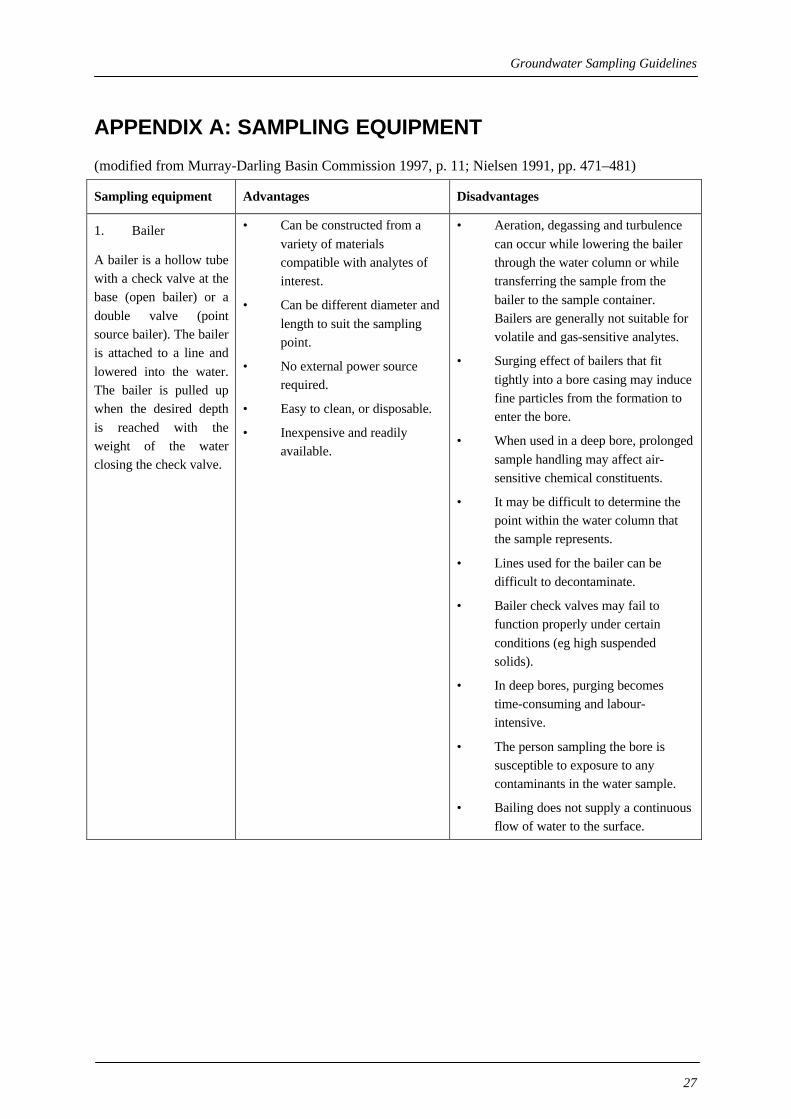
Groundwater Sampling Guidelines
27
APPENDIX A: SAMPLING EQUIPMENT
(modified from Murray-Darling Basin Commission 1997, p. 11; Nielsen 1991, pp. 471–481)
Sampling equipment Advantages Disadvantages
1. Bailer
A bailer is a hollow tubewith a check valve at thebase (open bailer) or a
double valve (pointsource bailer). The baileris attached to a line and
lowered into the water.The bailer is pulled upwhen the desired depth
is reached with theweight of the waterclosing the check valve.
• Can be constructed from a
variety of materialscompatible with analytes ofinterest.
• Can be different diameter and
length to suit the samplingpoint.
• No external power sourcerequired.
• Easy to clean, or disposable.
• Inexpensive and readilyavailable.
• Aeration, degassing and turbulence
can occur while lowering the bailerthrough the water column or whiletransferring the sample from the
bailer to the sample container.Bailers are generally not suitable forvolatile and gas-sensitive analytes.
• Surging effect of bailers that fit
tightly into a bore casing may inducefine particles from the formation toenter the bore.
• When used in a deep bore, prolonged
sample handling may affect air-sensitive chemical constituents.
• It may be difficult to determine thepoint within the water column thatthe sample represents.
• Lines used for the bailer can bedifficult to decontaminate.
• Bailer check valves may fail tofunction properly under certain
conditions (eg high suspendedsolids).
• In deep bores, purging becomestime-consuming and labour-intensive.
• The person sampling the bore issusceptible to exposure to anycontaminants in the water sample.
• Bailing does not supply a continuousflow of water to the surface.

Environment Protection Authority
28
2. Inertial lift pumpThis pump consists of afoot valve at the end of a
flexible tube which runsinto the water. Initiallythe water column in the
tube is equal to that inthe well. An initial rapidupstroke lifts the water
column in the tubing adistance equal to thestroke length, on the
down stroke the footvalve opens allowingfresh water to enter the
tube.
• Simple construction,inexpensive.
• Manual, gas or electric motor
driven.• Good for sediment-clogged
bores.
• If dedicated, avoids crosscontamination.
• For use primarily in small diameterbores as large bores increase thepossibility of tube sway.
• Pumping action agitates bore,introducing suspended material.
• Works optimally with deep
installation of tubing. This mayresult in the bore not being properlypurged.
• Low-flow capacity.
3. Syringe devicesA syringe or similar
device attached to tubingis lowered to a selecteddepth in the water
column. Suction isapplied to the tubing andthe syringe, filling the
syringe with water.
• Neither aeration nordegassing of the sampleoccurs, as the sample does notcome in contact with theatmosphere.
• Can be made of any material.
• Inexpensive, highly portableand simple to operate.
• Can be used in small diameterbores.
• Sample can be collected atvarious intervals
• Can be used as samplecontainer, thereby reducingthe potential for crosscontamination.
• Inefficient for collecting largevolumes.
• Syringes cannot be used for purging.
• Sample contamination bycomponents of ‘home-made’ syringe
sampling devices is possible unlessfabrication materials are carefullyselected.
• The use of syringes is limited to
water with a low suspended solidscontent as some leakage may occuraround the plunger when syringes are
used to sample water containing highsuspended solids.
4. Gas-drive devicesPositive gas pressureapplied to the surface of
water within the samplechamber forces thesample to the surfacethrough an open tube.
• Relatively portable
• Readily available
• Inexpensive
• Some are suitable for boredevelopment – depends onyield rate of device
• Can provide delivery of
sample at a controlled, nearlycontinuous rate.
• If air or oxygen is used as the drivinggas, oxidation may occur, causingprecipitation of metals and gas
stripping of volatiles. CO2 may alsobe driven from the sample causing apH shift. Consequently, air-lift
sampling may not be appropriate formany gas sensitive analytes.
• Gas stripping of volatiles may occur.
• An air compressor or largecompressed air tanks must be
transported to deep bores, reducingportability.
• Excessive air pressure can rupturegas entry or discharge tubing.

Groundwater Sampling Guidelines
29
5. Suction liftpumps
Suction lift pumps apply
a vacuum to either thebore casing or to tubingthat runs from the pump
to the desired samplingdepth.
• Highly portable.
• Readily available.
• Flow rate can be controlled.
• Inexpensive.
• Can be constructed for smalldiameter bores.
• With peristaltic pumps, thepump does not come in
contact with the sample –only the tubing contacts thesample
• Limited sampling depth (6–9 m)
• The application of strong negativepressure (suction) causes degassingof the sample and loss of volatiles.
• Potential for hydrocarbon
contamination of samples due to useof petrol or diesel for running thepump.
6. Gas-operated
piston pumpGas-operated pistonpumps consist of one or
more pistons movinginside a submergedcylinder or barrel. When
gas pressure drives thepiston up and down,one-way check valves
direct water moved bythe pistons to thesurface.
• Sample is isolated from the
driving gas, therefore noaeration of sample occurs.
• The pump provides acontinuous sample overextended periods of time.
• Easy to operate.
• Flow rates can be controlledby varying the driving gaspressure.
• Can achieve pump lifts of 100m.
• The pump’s valving mechanism may
cause a series of pressure drops inthe sample, leading to sampledegassing and pH changes.
• Unless the pump intake is filtered,
particulate matter may damage thepump’s intricate valving mechanism.
• Not highly portable – it must bevehicle mounted.
7. Bladder pumpA flexible bladder within
the device has checkvalves at each end. Thepump is lowered into the
water, gas from theground surface is cycledbetween the bladder and
sampler wall, forcingwater to enter thebladder and be driven up
the discharge line.
• Sample is isolated from thedriving gas, minimising the
problems of sample aerationand gas stripping.
• Samples collected with thesedevices lose very little of
even the most volatileconstituents (Parker 1994).
• Portable, small diameter.
• Pumping rate of most of thesepumps can be controlled to
allow for both bore purgingand collection of large samplevolumes.
• Most models are capable ofpump lifts greater than 60 m.
• Deep sampling requires largevolumes of gas and longer cycles,
thus increasing operating time andexpense and reducing portability.
• Check valves in some pumps mayfail in water with high suspendedsolids content.
• Most pump models are expensive.
• Minimum rate of sample dischargeof some models may be higher thanideal for sampling of volatilecompounds.

Environment Protection Authority
30
8. Gear-driveelectricsubmersible
pumpAn electric motor rotatesa set of gears which
drives the sample up thedischarge line.
• Constructed from inert ornearly inert materials.
• Wide range of diameters.
• Readily available.
• High pumping rates arepossible for removal of largevolumes.
• Provides a continuous sampleover extended periods.
• Conventional units are unable topump sediment-laden water withoutincurring damage to pump.
• Smallest diameter pump is relativelyexpensive.
• No control over flow rates.
9. Submersiblecentrifugal pump
A submersible electricalmotor drives an impellerin the pump, which
creates pressure andforces the sample up adischarge line. Can also
comprise of an impellerrotating inside borecasing rather than pump
housing.
• Small diameter pumps can beoperated at variable rates.
• Constructed from inert ornearly inert materials.
• Portable.
• Pumping rate of these pumpscan be varied.
• Does not handle viscous fluidsefficiently.
• Conventional large diameter
submersible centrifugal pumps aresubject to excessive wear in abrasiveor corrosive waters.
10. Helical-rotor
pumpUses an electricallydriven rotor-stator
assembly that moves thewater through aprogression of cavities to
the discharge line,forcing a water sampleup the discharge line.
• Portable and relatively easy totransport.
• High pumping rates arepossible.
• Constructed from inert ornearly inert material.
• The flow rate cannot be controlled.
• High pumping rates may lead to
creation of turbulence which maycause changes to sample chemistry.
• Thorough cleaning and repair in thefield may be difficult, as the pump isdifficult to disassemble.
• Water with high suspended solidscontent can cause operationalproblems.
• The pump must be cycled on/off
every 20 minutes to avoid over-heating.

Groundwater Sampling Guidelines
31
APPENDIX B: GROUNDWATER SAMPLING DEVICE MATRIXThis table is provided as a general guide only. The selection of an appropriate device will depend on the objectives of the investigation, the performance and properties of the deviceand the environmental conditions. Under certain conditions a combination of sampling devices should be considered and some devices may not be appropriate for all parameters.
GROUNDWATER PARAMETERS
INORGANIC ORGANIC BIOLOGICAL
Sampling devicevv MinimumBoreDiameterFF
SampleDeliveryRate orVolume==
EC pH Redox Majorions
Tracemetals
Nitratefluoride
Dissolvedgases
Non-volatile
Volatile TOC TOX Coliform bacteria
Bailer (open) 13 mm variable • ☼ ☼ • • • ☼ • ☼ ☼ ☼ •
Point source bailer 13 mm variable • • • • • • ☼ • ☼ • • •
Gra
b
Syringe 39 mm 0.05 – 0.1litres
• • • • • • ☼ • • ☼ ☼ •
Gear-drive 51 mm 0 – 2.3 lpm • • • • • • • • • • • ☼
Bladder pump 39 mm 0-9.lpm • • • • • • • • • • • •
Helical rotor 52 mm 0-5.4 lpm • • • • • • • • • • • ☼
Piston pump 39 mm 0 – 2.3 lpm • ☼ ☼ • • • ☼ • • ☼ ☼ ☼Posi
tive
Dis
plac
emen
t(S
ubm
ersi
ble)
Centrifugal (low rate) 52 mm variable • • • • • • • • • • • •
Peristaltic 13 mm 0.05 – 1.4lpm
• ☼ ☼ • • • ☼ • ☼ ☼ ☼ •
Gas-lift pump 26 mm variable ☼ ☼ ☼ ☼ ☼ ☼ ☼ ☼ ☼ ☼ ☼ ☼
Suct
ion
Lif
t
Gas
Con
tact
Gas drive 26 mm 0.1 lpm • ☼ ☼ • ☼ • ☼ • ☼ ☼ ☼ ☼
v It is assumed that existing monitoring bores are properly installed and constructed of materials suitable for detection of the parameters of interest.
F Converted from imperial units to metric units.
= Sample delivery rates and volumes are average ranges based on typical field conditions. Actual delivery rates are a function of diameter of monitoring bore, size and capacity of samplingdevice, hydrogeological conditions and depth to sampling point. For all devices, delivery rate should be carefully controlled to prevent aeration or degassing of the sample.
• Indicates device is generally suitable for application (assuming device is cleaned and operated properly and is constructed of suitable materials).
☼ Indicates device may be unsuitable or is untested for application.
Source: Modified from USEPA 1992
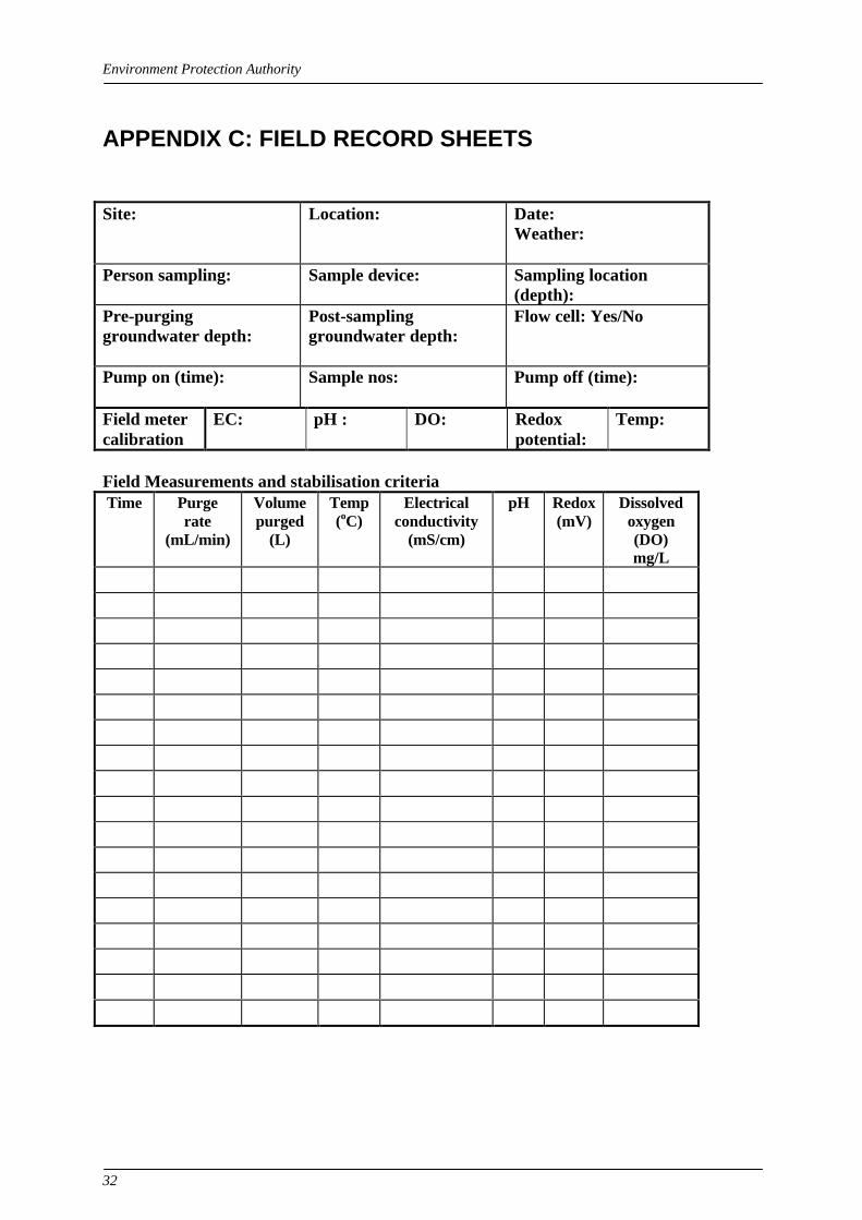
Environment Protection Authority
32
APPENDIX C: FIELD RECORD SHEETS
Site: Location: Date:Weather:
Person sampling: Sample device: Sampling location(depth):
Pre-purginggroundwater depth:
Post-samplinggroundwater depth:
Flow cell: Yes/No
Pump on (time): Sample nos: Pump off (time):
Field metercalibration
EC: pH : DO: Redoxpotential:
Temp:
Field Measurements and stabilisation criteriaTime Purge
rate(mL/min)
Volumepurged
(L)
Temp(oC)
Electricalconductivity
(mS/cm)
pH Redox(mV)
Dissolvedoxygen(DO)mg/L
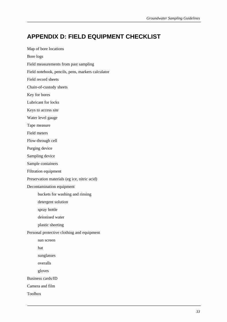
Groundwater Sampling Guidelines
33
APPENDIX D: FIELD EQUIPMENT CHECKLIST
Map of bore locations
Bore logs
Field measurements from past sampling
Field notebook, pencils, pens, markers calculator
Field record sheets
Chain-of-custody sheets
Key for bores
Lubricant for locks
Keys to access site
Water level gauge
Tape measure
Field meters
Flow-through cell
Purging device
Sampling device
Sample containers
Filtration equipment
Preservation materials (eg ice, nitric acid)
Decontamination equipment
buckets for washing and rinsing
detergent solution
spray bottle
deionised water
plastic sheeting
Personal protective clothing and equipment
sun screen
hat
sunglasses
overalls
gloves
Business cards/ID
Camera and film
Toolbox
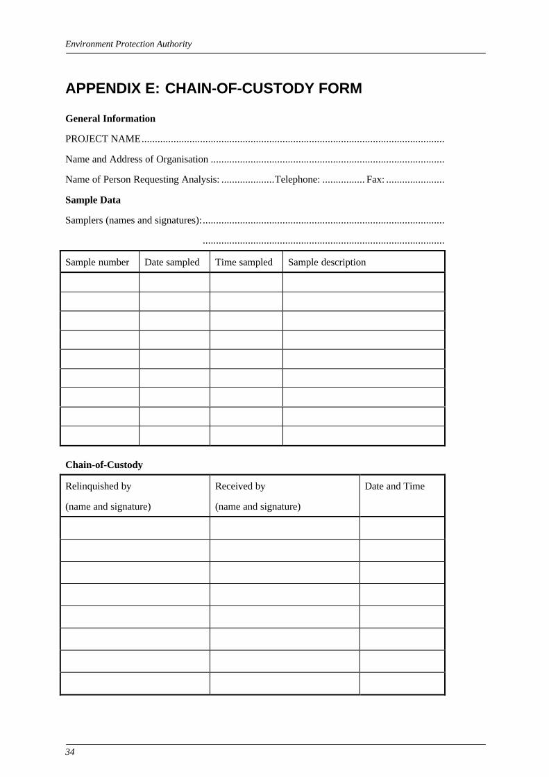
Environment Protection Authority
34
APPENDIX E: CHAIN-OF-CUSTODY FORM
General Information
PROJECT NAME..................................................................................................................
Name and Address of Organisation ........................................................................................
Name of Person Requesting Analysis: ....................Telephone: ................ Fax: ......................
Sample Data
Samplers (names and signatures):...........................................................................................
...........................................................................................
Sample number Date sampled Time sampled Sample description
Chain-of-Custody
Relinquished by
(name and signature)
Received by
(name and signature)
Date and Time
Groundwater Sampling Guidelines
35
REFERENCES
Agriculture and Resource Management Council of Australia and New Zealand (ARMCANZ), 1997,Minimum Construction Requirements for Water Bores in Australia.
Aller, L. and Gardner, S. 1995, ‘Well design, construction and development’, Ground Water Sampling– A Workshop Summary, EPA/600/R–94/205, Washington, pp. 72–81.
Barcelona, M.J. 1995, ‘Sampling program purpose and design considerations’, Ground WaterSampling – A Workshop Summary, EPA/600/R–94/205, Washington, pp. 12–15.
Barcelona, M.J., Helfrich, J.A. and Garske, E.E. 1985, ‘Sampling tubing effects on groundwatersamples’, Analytical Chemistry, vol 57, pp. 460–464.
Barcelona, M.J., Helfrich, J.A., Garske, E.E. and Gibb, J.P. 1984, ‘A laboratory evaluation of groundwater sampling mechanisms’, Ground Water Monitoring Review, Spring 1984, pp. 32–41.
Barcelona, M.J., McCarthy J.F., Brown J.R., Puls R.W. 1995, Ground Water Sampling – A WorkshopSummary, EPA/600/R–94/205, Washington, pp. 1–4.
Barcelona M.J., Wehrmann H.A. and Varljen M.D. 1994, ‘Reproducible well-purging procedures andvoc stabilization criteria for ground-water sampling’, Groundwater, 32 (1).
Canadian Council of Ministers of the Environment 1993, Guidance Manual on Sampling Analysis,and Data Management for Contaminated Sites Volume I: Main Report, Report CCME EPC-NCS62E.
EPA 2000, A Guide to the Sampling and Analysis of Waters, Wastewaters, Soils and Wastes, EPAPublication 441, 7th edition, Environment Protection Authority (Victoria).
EPA 2000, Hydrogeological Assessments (Groundwater Quality), EPA Publication 668, EnvironmentProtection Authority (Victoria) (forthcoming).
Gillespie, G.A., 1992, ‘An effective monitoring screen for fine sand aquifers,’ Current Practices inGround Water and Vadose Zone Investigations, ASTM STP 1118, David M. Nielsen and Martin N.Sara, Editors, American Society of Testing and Materials, Philadelphia, 1992.
Murray-Darling Basin Commission 1997, Murray-Darling Basin Groundwater Sampling Guidelines,MDBC Technical Report No 3, Technical Report Series, Groundwater Working Group, Murray-Darling Basin Commission, August 1997.
National Association of Testing Authorities 1993, General Requirements for Registration:Supplementary Requirements: Chemical Testing.
National Association of Testing Authorities 1994, Technical Note No. 19, Liquid-in-glassThermometers – Selection, Use and Calibration.
Nielsen, D.M. 1991, Practical Handbook of Ground-Water Monitoring, Lewis Publishers, New York,pp. 449–499.
Parker, L.V. 1994, ‘The Effects of Ground Water Sampling Devices on Water Quality: A LiteratureReview’, Ground Water Monitoring and Remediation, Spring 1994, pp. 130–141.
Parker, L.V. 1992, ‘Suggested Guidelines for the Use of PTFE, PVC and Stainless Steel in Samplersand Well Casings’, Current Practices in Ground Water and Vadose Zone Investigations, AmericanSociety of Testing and Materials (ASTP) 1118, David M. Nielsen and Martin N. Sara, Editors, ASTP,Philadelphia 1992, pp. 217–225.
Environment Protection Authority
36
Puls, R.W. 1995, ‘Use of low flow or passive sampling techniques for sampling groundwater’,Ground Water Sampling - A Workshop Summary, EPA/600/R-94/205, Washington, pp. 17-20.
Puls, R.W. and Barcelona, M.J. 1989, ‘Groundwater sampling for metals analyses’, EPA SuperfundGround Water Issue, EPA/540/4–89/001, Washington.
Puls, R.W. and Barcelona, M.J. 1996, ‘Low-flow (minimal drawdown) ground-water samplingprocedures’, EPA Ground Water Issue, EPA/540/S-95/504, Washington.
Puls, R.W., Clark, D.A., Bledsoe, D., Powell R.M., and Paul C.J. 1992, ‘Metals in groundwater:sampling artefacts and reproducibility’, Hazardous Waste & Hazardous Materials, 9 (2), pp. 149–162.
Puls, R.W. and Powell, R.M. 1992, ‘Acquisition of representative ground water quality samples formetals,’ Ground Water Monitoring Review, Summer, pp 167-175.
Puls, R.W. and Powell, R.M., 1997. ‘Hitting the bull’s-eye in groundwater sampling’, PollutionEngineering, June 1997 pp. 50–54.
Standards Australia 1994, AS/NZ 1715: 1994, Selection, Use and Maintenance of RespiratoryProtective Devices, Standards Australia, NSW.
Standards Australia/New Zealand 1994, AS/NZ ISO 8402:1994 Quality Management and QualityAssurance - Vocabulary, Standards Australia, NSW.
Standards Australia/New Zealand 1998, AS/NZ 5667.1:1998 Water Quality – Sampling, Part 1:Guidance on the Design of Sampling Programs, Sampling Techniques and the Preservation andHandling of Samples, Standards Australia, NSW.
Standards Australia/New Zealand 1998, AS/NZ 5667.11:1998 Water Quality – Sampling, Part 11:Guidance on Sampling of Groundwaters, Standards Australia, NSW.
Saar, R.A. 1997, ‘Filtration of ground water samples: a review of industry practice’, Ground WaterMonitoring and Remediation, Winter 1997, pp. 56–62.
USEPA 1992, RCRA Ground-Water Monitoring: Draft Technical Guidance, Office of Solid Waste,Washington, DC EPA/530/R–93/001, NTIS PB 93–139350.
Vroblesky, D.A. and Hyde, W.T. 1997, ‘Diffusion samplers as an inexpensive approach to monitoringVOCs in ground water’, Ground Water Monitoring Review, Summer, pp. 177–184.