Grounding Systems - Thomas & Betts Canada Systems - Thomas & Betts Canada
98
www.tnb.ca D1 Grounding Systems EZGround ® Thomas & Betts offers a complete range of grounding products including mechanical, compression and exothermic systems. Whatever the application, there is a Thomas & Betts grounding solution to meet your requirements. Introduction .....................................................D2–D5 Signal Reference Grid Connectors ........................................ D6 Clamps ........................................................D7–D18 Service Post Connectors ..........................................D19–D20 Transformer Tank Ground Connectors.................................... D21 Conduit Hubs ...................................................... D22 Lay-In Lug Connectors ............................................... D23 Ground Plates ..................................................D24–D25 Ground Tap Connectors, Ground Rod Tap Connectors ....................D26–D27 Ground Rod to Grid Connectors, Ground Grid Connectors ..................... D28 Cable-to-Cable or Cable-to-Rod Connectors ............................... D29 Two Cables to Ground Rod ............................................ D30 Grounding Grid Connectors ........................................... D31 C-Taps .......................................................D32–D33 Pigtail Connectors ................................................... D34 Grounding Studs .................................................... D35 Bus Bar Connectors ................................................. D36 Ground Rods ...................................................D37–D39 Ground Rod Drivers.................................................. D40 Flexible Braid ...................................................... D41 Exothermic Welding System .......................................D42–D95 Competitive Cross Reference ......................................D96–D98 Table of Contents
Transcript of Grounding Systems - Thomas & Betts Canada Systems - Thomas & Betts Canada
w w w . t n b . c a D1
Grounding SystemsEZGround ®
Thomas & Betts offers a complete range of grounding products including mechanical, compression and exothermic systems. Whatever the application, there is a Thomas & Betts grounding solution to meet your requirements.
Introduction . . . . . . . . . . . . . . . . . . . . . . . . . . . . . . . . . . . . . . . . . . . . . . . . . . . . .D2–D5
Signal Reference Grid Connectors . . . . . . . . . . . . . . . . . . . . . . . . . . . . . . . . . . . . . . . .D6
Clamps . . . . . . . . . . . . . . . . . . . . . . . . . . . . . . . . . . . . . . . . . . . . . . . . . . . . . . . .D7–D18
Service Post Connectors . . . . . . . . . . . . . . . . . . . . . . . . . . . . . . . . . . . . . . . . . .D19–D20
Transformer Tank Ground Connectors . . . . . . . . . . . . . . . . . . . . . . . . . . . . . . . . . . . .D21
Conduit Hubs . . . . . . . . . . . . . . . . . . . . . . . . . . . . . . . . . . . . . . . . . . . . . . . . . . . . . .D22
Lay-In Lug Connectors . . . . . . . . . . . . . . . . . . . . . . . . . . . . . . . . . . . . . . . . . . . . . . .D23
Ground Plates . . . . . . . . . . . . . . . . . . . . . . . . . . . . . . . . . . . . . . . . . . . . . . . . . .D24–D25
Ground Tap Connectors, Ground Rod Tap Connectors . . . . . . . . . . . . . . . . . . . .D26–D27
Ground Rod to Grid Connectors, Ground Grid Connectors . . . . . . . . . . . . . . . . . . . . .D28
Cable-to-Cable or Cable-to-Rod Connectors . . . . . . . . . . . . . . . . . . . . . . . . . . . . . . .D29
Two Cables to Ground Rod . . . . . . . . . . . . . . . . . . . . . . . . . . . . . . . . . . . . . . . . . . . .D30
Grounding Grid Connectors . . . . . . . . . . . . . . . . . . . . . . . . . . . . . . . . . . . . . . . . . . .D31
C-Taps . . . . . . . . . . . . . . . . . . . . . . . . . . . . . . . . . . . . . . . . . . . . . . . . . . . . . . .D32–D33
Pigtail Connectors . . . . . . . . . . . . . . . . . . . . . . . . . . . . . . . . . . . . . . . . . . . . . . . . . . .D34
Grounding Studs . . . . . . . . . . . . . . . . . . . . . . . . . . . . . . . . . . . . . . . . . . . . . . . . . . . .D35
Bus Bar Connectors . . . . . . . . . . . . . . . . . . . . . . . . . . . . . . . . . . . . . . . . . . . . . . . . .D36
Ground Rods . . . . . . . . . . . . . . . . . . . . . . . . . . . . . . . . . . . . . . . . . . . . . . . . . . .D37–D39
Ground Rod Drivers . . . . . . . . . . . . . . . . . . . . . . . . . . . . . . . . . . . . . . . . . . . . . . . . . .D40
Flexible Braid . . . . . . . . . . . . . . . . . . . . . . . . . . . . . . . . . . . . . . . . . . . . . . . . . . . . . .D41
Exothermic Welding System . . . . . . . . . . . . . . . . . . . . . . . . . . . . . . . . . . . . . . .D42–D95
Competitive Cross Reference . . . . . . . . . . . . . . . . . . . . . . . . . . . . . . . . . . . . . .D96–D98
Table of Contents
Tap
Main
T
H
T
H
A
B

w w w . t n b . c aD2
Grounding SystemsEZGround ®
Introduction
Compression Method Grounding Connectors save 50 – 75% in time and labor costs• Eliminates exothermic welding• Reduces time and labor costs• Minimizes possibility of poor connections
Thomas & Betts introduces a method of compression to replace exothermic welding and its associated disadvantages. This compression method is designed to provide quick, reliable connections for grid grounding at significantly lower installed costs because compression connectors install in less time, in any weather, and are unaffected by moisture, reducing downtime. In addition, our compression connectors for grid grounding require no special training for installation. They are made of high-conductivity wrought and cast copper, and are used for connecting and tapping cross grid, loop lines and ground rods for direct burial or concrete embedded ground grid systems. The Thomas & Betts compression system uses standard electrical connector installation tools.
This installation method results in a long-lasting low-installed cost connection. You can install it and forget it.
Before compression, typical cable connector cross section of cable and connector consists of about 75% metal and 25% air. After Thomas & Betts method compression, the cross section shows
100% metal with virtually no air spaces.
Meets all applicable specifications
Thomas & Betts grid and ground rod connectors satisfy the requirements of CEC SECTION 10 for connecting to the Grounding Electrode System. They also meet the requirements of UL and CSA standards being acceptable as grounding and bonding equipment suitable for direct burial. Thomas & Betts grid and ground rod connectors also satisfy the recommended practice for the selection of grounding connector joints described in IEEE 837 standard for qualifying permanent connections used in substation grounding.
The connectors conform to the following IEEE Standard 837 requirements:• 350°C current cycling• Freeze-thaw test• Accelerated aging – nitric acid/salt spray• Mechanical, tensile and electromagnetic
force (EMF) criteria• Install in any weather – cut downtime• Enhance safety• Easy to install – no special training
SectionD-grounding-systems.indd 2 6/6/2017 9:42:42 AM

w w w . t n b . c a D3
Grounding SystemsEZGround ®
Introduction
TBM14M(Suggested tool for EZGround connectors
to ground rods up to 5/8 in. diameter.)
Reliable installations through compression connections
Dies that are used in Thomas & Betts hand and hydraulic tools contain the die code numbers which are engraved on the compression surface of the die. Under compression, this number becomes embossed on the completed connection for inspection purposes.
The inspector compares the die code number embossed on the connector with the die table to ensure that the proper connector was compressed with the correct die for that particular size conductor.
Before Compression
After Compression
This installation method results in a long-lasting, low-installed cost connection. You can install it and forget it. Before compression, typical cable connector cross section of cable and connector consists of about 75% metal and 25% air. After Thomas & Betts method compression, the cross section shows 100% metal with virtually no air spaces.
SectionD-grounding-systems.indd 3 6/6/2017 9:42:44 AM
w w w . t n b . c aD4
Grounding SystemsEZGround ®
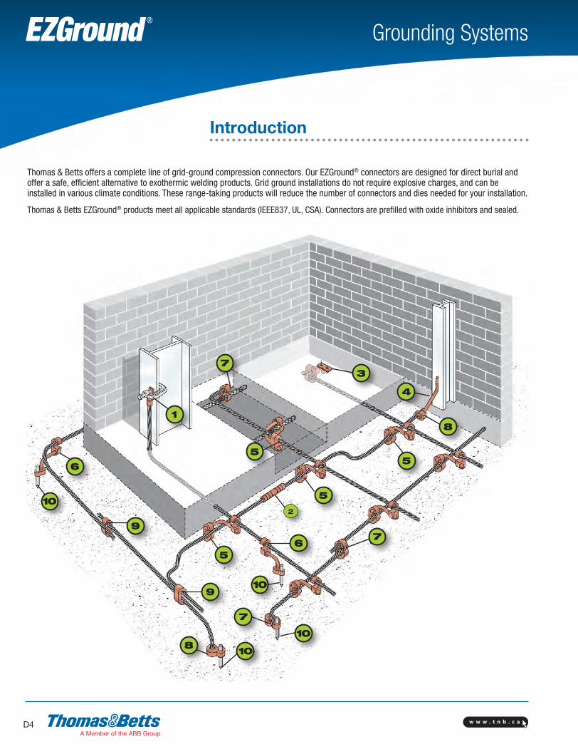
Thomas & Betts offers a complete line of grid-ground compression connectors. Our EZGround® connectors are designed for direct burial and offer a safe, efficient alternative to exothermic welding products. Grid ground installations do not require explosive charges, and can be installed in various climate conditions. These range-taking products will reduce the number of connectors and dies needed for your installation.
Thomas & Betts EZGround® products meet all applicable standards (IEEE837, UL, CSA). Connectors are prefilled with oxide inhibitors and sealed.
Introduction
10
3
9
9
6
6
2
5
55
5
1
10
10
4
8
8
7
7
7
10
SectionD-grounding-systems.indd 4 6/6/2017 9:42:54 AM
w w w . t n b . c a D5
Grounding SystemsEZGround ®
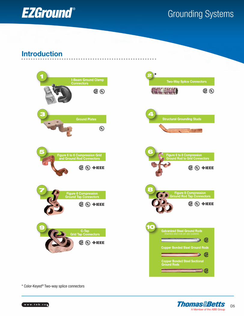
I-Beam Ground Clamp Connectors
1Two-Way Splice Connectors
2
Ground Plates3
Structural Grounding Studs4
Figure 6 to 6 Compression Grid and Ground Rod Connectors
5Figure 6 to 8 Compression Ground Rod to Grid Connectors
6
Figure 6 Compression Ground Tap Connectors
7 Figure 8 Compression Ground Rod Tap Connectors
8
C-Tap Grid Tap Connectors
9 10Galvanized Steel Ground Rods
(Stainless steel rods are also available)
Copper Bonded Steel Ground Rods
Copper Bonded Steel Sectional Ground Rods
Introduction
*
* Color-Keyed® Two-way splice connectors
SectionD-grounding-systems.indd 5 6/6/2017 9:42:58 AM
w w w . t n b . c aD6
Grounding SystemsEZGround ®
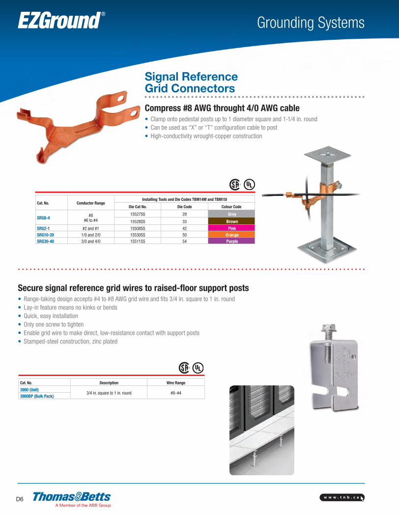
Cat. No. Conductor RangeInstalling Tools and Die Codes TBM14M and TBM15I
Die Cat No. Die Code Colour Code
SRG8-4 #8#6 to #4
15527SS 29 Grey
15528SS 33 Brown
SRG2-1 #2 and #1 15508SS 42 PinkSRG10-20 1/0 and 2/0 15530SS 50 OrangeSRG30-40 3/0 and 4/0 15511SS 54 Purple
Signal Reference Grid Connectors
Compress #8 AWG throught 4/0 AWG cable• Clamp onto pedestal posts up to 1 diameter square and 1-1/4 in. round• Can be used as “X” or “T” configuration cable to post• High-conductivity wrought-copper construction
Secure signal reference grid wires to raised-floor support posts• Range-taking design accepts #4 to #8 AWG grid wire and fits 3/4 in. square to 1 in. round• Lay-in feature means no kinks or bends• Quick, easy installation• Only one screw to tighten• Enable grid wire to make direct, low-resistance contact with support posts• Stamped-steel construction, zinc plated
Cat. No. Description Wire Range
3900 (Unit)3/4 in. square to 1 in. round #8–#4
3900BP (Bulk Pack)
SectionD-grounding-systems.indd 6 6/6/2017 9:43:02 AM

w w w . t n b . c a D7
Grounding SystemsEZGround ®
3844For armored and unarmored wire
3840
3849 3826
Cat. No. Ground Wire Size Water Pipe Size
2-TB
#6, #4, #2 AWG
1/2 in., 3/4 in., 1 or rebar 4-10
3-TB 1-1/4 in., 1-1/2 in. or 2 in.4 2-1/2 in., 3 in. or 3-1/2 in.5-TB 4 in., 4-1/2 in. or 5 in.6 6 in.
Malleable iron crossbar, steel U-Bolt c/w copper cable clamp with serrations.
Cat. No. Ground Wire Size Water Pipe Size
3902
#4–4/0 AWG
1/2 in.–13903 1-1/4 in.–2 in.3904 2-1/2 in.–3-1/2 in.3905-TB 4 in.–5 in.3906-TB 6 in.3907 8 in.3908 10 in.3909-TB 12 in.
Material: Steel U-bolt and nut c/w bronzed aluminum cap and crossbar cadmium plated plus gold chromate finish.
Cat. No. Ground Wire Size Water Pipe Size
3902BU*
#4–4/0 AWG
1/2 in.–13903BU* 1-1/4 in.–2 in.3904BU* 2-1/2 in.–3-1/2 in.3905BU* 4 in.–5 in.3906BU* 6 in.3907BU* 8 in.3908BU* 10 in.3909BU* 12 in.
Material: Bronze U-bolt and nut c/w bronzed aluminum cap and crossbar with a brite dip finish. *UL Listed for Direct Burial.
Ground Clamp Accessories
Cat. No. Description For use with
10102-TB 1-1/4 to 1-1/2 in. cables #8–#2 Ground wireMaterial: Malleable iron, zinc plated.
Cat. No. For use with
10105 Single conductors #4 solid to 2/0 str.10109 Single conductors 2/0 solid to 4/0 str.
Ground Clamps
Cat. No. Material Water Pipe, Copper Tubing Size
Ground Rod Size
3826* Malleable Iron1/2 in., 3/4 in. 1/2 in.–1
3846* Bronze
3840-TB• Malleable Iron 1/2 in., 3/4 in. or 1
* For unarmored copper wires #6, #4 AWG. UL approved for direct burial. • #8 thru #4 AWG. Not CSA Certified
Ground Clamps for K&L Grade Copper Tubing Only
Cat. No. Ground Wire Size Water Pipe, Copper Tubing Size
3844*#8–#4 AWG
1/2 in.–13888** 1/2 in.–1 also rebar 4–10
* With Steel Screws.** UL approved for direct burial. Silicon Bronze Screws.
3826
Clamps
3840-TB
3844For armored and unarmored wire
3840
3849 3826 3844For armored and unarmored wire
3840
3849 3826
3844For armored and unarmored wires.
Waterpipe Ground Clamps Waterpipe Ground Clamps Waterpipe Ground Clamps
SectionD-grounding-systems.indd 7 6/6/2017 9:43:04 AM
w w w . t n b . c aD8
Grounding SystemsEZGround ®
E
D
Clamps
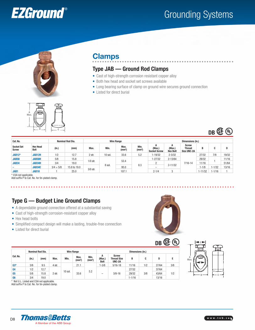
Type JAB — Ground Rod Clamps• Cast of high-strength corrosion resistant copper alloy• Both hex head and socket set screws available• Long bearing surface of clamp on ground wire secures ground connection• Listed for direct burial
Cat. No. Nominal Rod Dia. Wire Range Dimensions (in.)
Socket Set Screw
Hex HeadBolt (in.) (mm) Max. Min. Max.
(mm2)Min.
(mm2)
A(Max.)
Socket Screw
A(Max.)
Hex Bolt
ScrewThread
Size UNC-2AB C D
JAB12* JAB12H 1/2 12.7 2 str. 10 sol. 33.6 5.2 1-19/32 2-3/32
7/16-14
27/32 7/8 19/32JAB58 JAB58H 5/8 15.8
1/0 str.8 sol.
53.48.3
1-27/32 2-13/64 29/321
11/16JAB34 JAB34H 3/4 19.0 2
2-11/3211/16 51/64
– JAB34C 3/4 + 5/8 15.8 to 19.03/0 str.
95.0 – 1-1/8 1-1/32 13/16JAB1 JAB1H 1 25.0 107.1 2-1/4 3 1-11/32 1-1/16 1
* CSA not applicable.Add suffix P to Cat. No. for tin-plated clamp.
Type G — Budget Line Ground Clamps• A dependable ground connection offered at a substantial saving• Cast of high-strength corrosion-resistant copper alloy• Hex head bolts• Simplified compact design will make a lasting, trouble-free connection• Listed for direct burial
Cat. No.
Nominal Rod Dia. Wire Range Dimensions (in.)
(in.) (mm) Max. Min. Max.(mm2)
Min.(mm2)
A(Max.)Bolt
ScrewThread Size
UNC-2AB C D E
G3* 3/8 9.5 4 str.
10 sol.
21.1
5.2
1-3/8 5/16-18 11/16 1/2 27/64 3/8G4 1/2 12.7
2 str. 33.6 – 3/8-1627/32
3/837/64
1/2G5 5/8 15.8 29/32 43/64G6 3/4 19.0 1-1/16 13/16
* Not U.L. Listed and CSA not applicable.Add suffix P to Cat. No. for tin-plated clamp.
D C
AMax.
E
C
AMax.
B
DB
DB
SectionD-grounding-systems.indd 8 6/6/2017 9:43:05 AM
w w w . t n b . c a D9
Grounding SystemsEZGround ®
Clamps
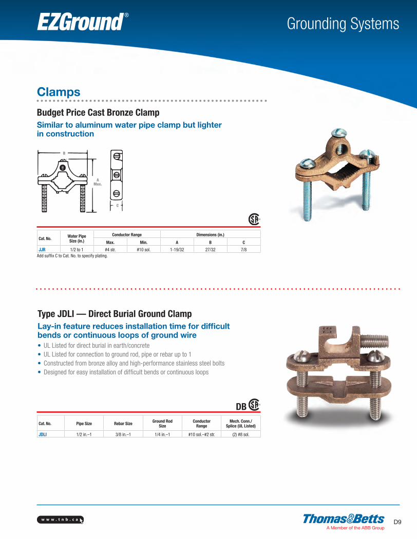
Budget Price Cast Bronze ClampSimilar to aluminum water pipe clamp but lighter in construction
Cat. No. Water PipeSize (in.)
Conductor Range Dimensions (in.)
Max. Min. A B C
JJR 1/2 to 1 #4 str. #10 sol. 1-19/32 27/32 7/8Add suffix C to Cat. No. to specify plating.
Cat. No. Pipe Size Rebar Size Ground RodSize
ConductorRange
Mech. Conn./Splice (UL Listed)
JDLI 1/2 in.–1 3/8 in.–1 1/4 in.–1 #10 sol.–#2 str. (2) #8 sol.
Type JDLI — Direct Burial Ground ClampLay-in feature reduces installation time for difficult bends or continuous loops of ground wire• UL Listed for direct burial in earth/concrete• UL Listed for connection to ground rod, pipe or rebar up to 1• Constructed from bronze alloy and high-performance stainless steel bolts• Designed for easy installation of difficult bends or continuous loops
B
AMax.
C
DB
SectionD-grounding-systems.indd 9 6/6/2017 9:43:06 AM
w w w . t n b . c aD10
Grounding SystemsEZGround ®
E
D
Clamps
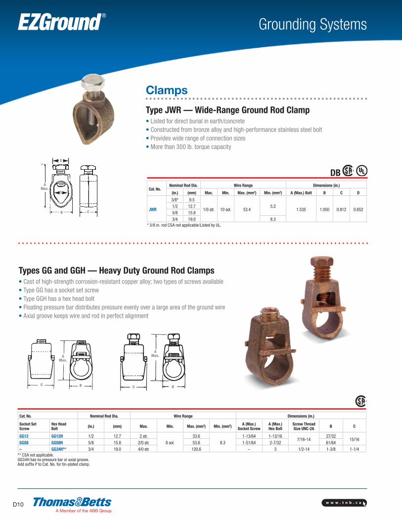
Type JWR — Wide-Range Ground Rod Clamp• Listed for direct burial in earth/concrete• Constructed from bronze alloy and high-performance stainless steel bolt• Provides wide range of connection sizes• More than 300 lb. torque capacity
Cat. No.Nominal Rod Dia. Wire Range Dimensions (in.)
(in.) (mm) Max. Min. Max. (mm2) Min. (mm2) A (Max.) Bolt B C D
JWR
3/8* 9.5
1/0 str. 10 sol. 53.45.2
1.535 1.050 0.812 0.6521/2 12.75/8 15.83/4 19.0 8.3
* 3/8 in. rod CSA not applicable/Listed by UL.
Cat. No. Nominal Rod Dia. Wire Range Dimensions (in.)
Socket SetScrew
Hex HeadBolt (in.) (mm) Max. Min. Max. (mm2) Min. (mm2) A (Max.)
Socket ScrewA (Max.)Hex Bolt
Screw ThreadSize UNC-2A B C
GG12 GG12H 1/2 12.7 2 str.8 sol.
33.68.3
1-13/64 1-13/167/16-14
27/3215/16
GG58 GG58H 5/8 15.8 2/0 str. 53.6 1-51/64 2-7/32 61/64– GG34H** 3/4 19.0 4/0 str. 120.6 – 3 1/2-14 1-3/8 1-1/4
** CSA not applicable.GG34H has no pressure bar or axial groove.Add suffix P to Cat. No. for tin-plated clamp.
C
E
AMax.
B
C B
AMax.
AMax.
C B
Types GG and GGH — Heavy Duty Ground Rod Clamps• Cast of high-strength corrosion-resistant copper alloy; two types of screws available• Type GG has a socket set screw• Type GGH has a hex head bolt• Floating pressure bar distributes pressure evenly over a large area of the ground wire• Axial groove keeps wire and rod in perfect alignment
DB
w w w . t n b . c a D11
Grounding SystemsEZGround ®
Clamps
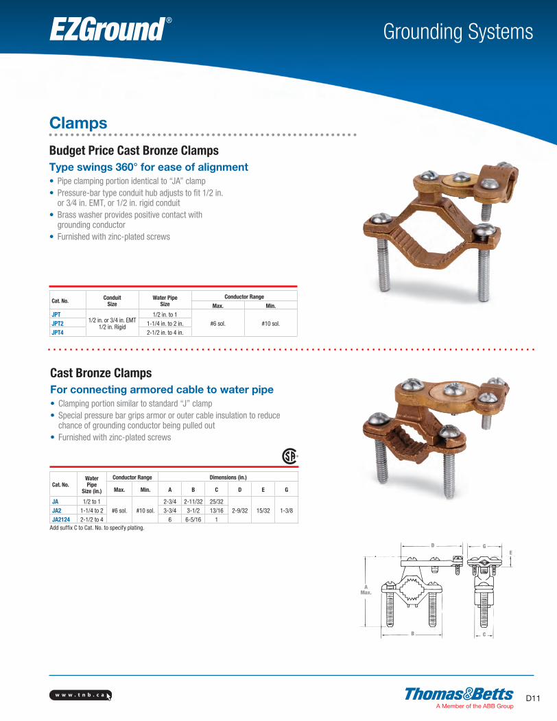
Budget Price Cast Bronze ClampsType swings 360° for ease of alignment• Pipe clamping portion identical to “JA” clamp• Pressure-bar type conduit hub adjusts to fit 1/2 in. or 3⁄4 in. EMT, or 1/2 in. rigid conduit• Brass washer provides positive contact with grounding conductor• Furnished with zinc-plated screws
Cat. No. ConduitSize
Water PipeSize
Conductor Range
Max. Min.
JPT1/2 in. or 3/4 in. EMT
1/2 in. Rigid
1/2 in. to 1#6 sol. #10 sol.JPT2 1-1/4 in. to 2 in.
JPT4 2-1/2 in. to 4 in.
Cast Bronze ClampsFor connecting armored cable to water pipe• Clamping portion similar to standard “J” clamp• Special pressure bar grips armor or outer cable insulation to reduce chance of grounding conductor being pulled out• Furnished with zinc-plated screws
Cat. No.WaterPipe
Size (in.)
Conductor Range Dimensions (in.)
Max. Min. A B C D E G
JA 1/2 to 1#6 sol. #10 sol.
2-3/4 2-11/32 25/322-9/32 15/32 1-3/8JA2 1-1/4 to 2 3-3/4 3-1/2 13/16
JA2124 2-1/2 to 4 6 6-5/16 1Add suffix C to Cat. No. to specify plating.
CB
EGD
AMax.
SectionD-grounding-systems.indd 11 6/6/2017 9:43:08 AM

w w w . t n b . c aD12
Grounding SystemsEZGround ®
Clamps
Cast Bronze Clamps for ConduitFor grounding rigid conduit systems• Continuity from rigid conduit system to ground provided by cast bronze threaded conduit hub• Hub swings 360° for easy alignment• Heavy brass washer protects clamped grounding conductor• Furnished with zinc-plated screws• Cast bronze pipe clamping portion identical to that used in “JA” clamp
Cat. No. Conduit Size (in.)
Water PipeSize (in.)
Conductor Range Dimensions (in.)
Max. Min. A B C D E G
JP121/2
1/2 to 1#6 sol.
#10 sol.
2-3/4 2-11/32 23/321-9/64 1 2-1/2JP212 1-1/4 to 2 3-3/4 3-1/2 13/16
JP212412 2-1/2 to 4 6 6-5/16 1JP34
3/41/2 to 1
#2/0 str.2-3/4 2-11/32 23/32
2-5/16
1-1/4 2-3/16JP234 1-1/4 to 2 3-3/4 3-1/2 13/16JP1
11/2 to 1
#3/0 str.2-3/4 2-11/32 23/32
1-1/2 2-3/8JP21 1-1/4 to 2 3-3/4 3-1/2 13/16JP21241 2-1/2 to 4 6 6-5/16 1
Add suffix C to Cat. No. to specify plating.
Cast Bronze Clamps with Copper StrapFlexible copper strap makes alignment easy• For grounding rigid conduit systems• Same features as “JP” clamp plus flexible copper strap• Strap helps protect conduit system from water system vibrations• Furnished with zinc-plated screws
Cat. No. Conduit Size(in.)
Water PipeSize (in.)
Conductor Range
Max. Min.
JPS12 1/21/2 to 1
6 sol.10 sol.JPS34 3/4 2/0 str.
JPS1 1 3/0 str.Add suffix C to Cat. No. to specify plating.
CB
D
EG
A
DB
SectionD-grounding-systems.indd 12 6/6/2017 9:43:08 AM

w w w . t n b . c a D13
Grounding SystemsEZGround ®
Clamps
Cast Bronze Ground ClampsConnect copper ground wire to water pipe, copper tubing or ground rods• High-strength, high-conductivity copper alloy (over 80% copper)• UL Approved for direct burial
Cat. No. Water Pipe Size (in.) Conductor Range
JD 1/2 to 1#2 str.–#10 str.
J2D 1-1/4 to 2
Type J — Cast Bronze Ground ClampsFor connecting grounding conductor to water pipe or copper tube• Cast of high-strength, highly conductive copper alloy• Screws plated for corrosion resistance• UL Listed
Cat. No. Water PipeSize (in.)
Conductor Range Dimensions (in.)
Max. Min. A B C
J 1/2 to 1
2 str. 10 sol.
2-3/4 2-11/32 23/32J2BB 1-1/4 to 2 3-3/4 3-1/2 13/16J2124 2-1/2 to 4 6 6-5/16
1J6 4-1/4 to 6 7-1/4 8-1/8
DB
CB
A(Max.)
SectionD-grounding-systems.indd 13 6/6/2017 9:43:09 AM
w w w . t n b . c aD14
Grounding SystemsEZGround ®
C
A
B
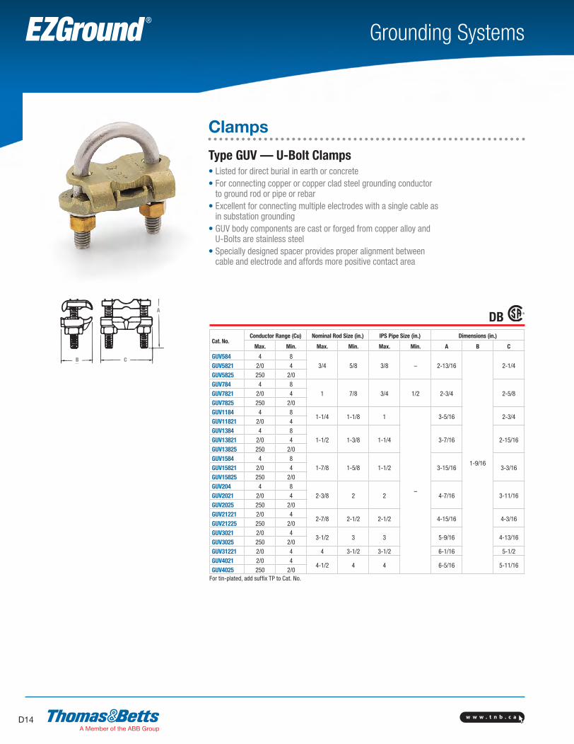
Clamps
Type GUV — U-Bolt Clamps• Listed for direct burial in earth or concrete• For connecting copper or copper clad steel grounding conductor
to ground rod or pipe or rebar• Excellent for connecting multiple electrodes with a single cable as
in substation grounding• GUV body components are cast or forged from copper alloy and
U-Bolts are stainless steel• Specially designed spacer provides proper alignment between
cable and electrode and affords more positive contact area
Cat. No.Conductor Range (Cu) Nominal Rod Size (in.) IPS Pipe Size (in.) Dimensions (in.)
Max. Min. Max. Min. Max. Min. A B C
GUV584 4 83/4 5/8 3/8 – 2-13/16
1-9/16
2-1/4GUV5821 2/0 4GUV5825 250 2/0GUV784 4 8
1 7/8 3/4 1/2 2-3/4 2-5/8GUV7821 2/0 4GUV7825 250 2/0GUV1184 4 8
1-1/4 1-1/8 1
–
3-5/16 2-3/4GUV11821 2/0 4GUV1384 4 8
1-1/2 1-3/8 1-1/4 3-7/16 2-15/16GUV13821 2/0 4GUV13825 250 2/0GUV1584 4 8
1-7/8 1-5/8 1-1/2 3-15/16 3-3/16GUV15821 2/0 4GUV15825 250 2/0GUV204 4 8
2-3/8 2 2 4-7/16 3-11/16GUV2021 2/0 4GUV2025 250 2/0GUV21221 2/0 4
2-7/8 2-1/2 2-1/2 4-15/16 4-3/16GUV21225 250 2/0GUV3021 2/0 4
3-1/2 3 3 5-9/16 4-13/16GUV3025 250 2/0GUV31221 2/0 4 4 3-1/2 3-1/2 6-1/16 5-1/2GUV4021 2/0 4
4-1/2 4 4 6-5/16 5-11/16GUV4025 250 2/0
For tin-plated, add suffix TP to Cat. No.
B C
A
DB
SectionD-grounding-systems.indd 14 6/6/2017 9:43:10 AM
w w w . t n b . c a D15
Grounding SystemsEZGround ®
Clamps
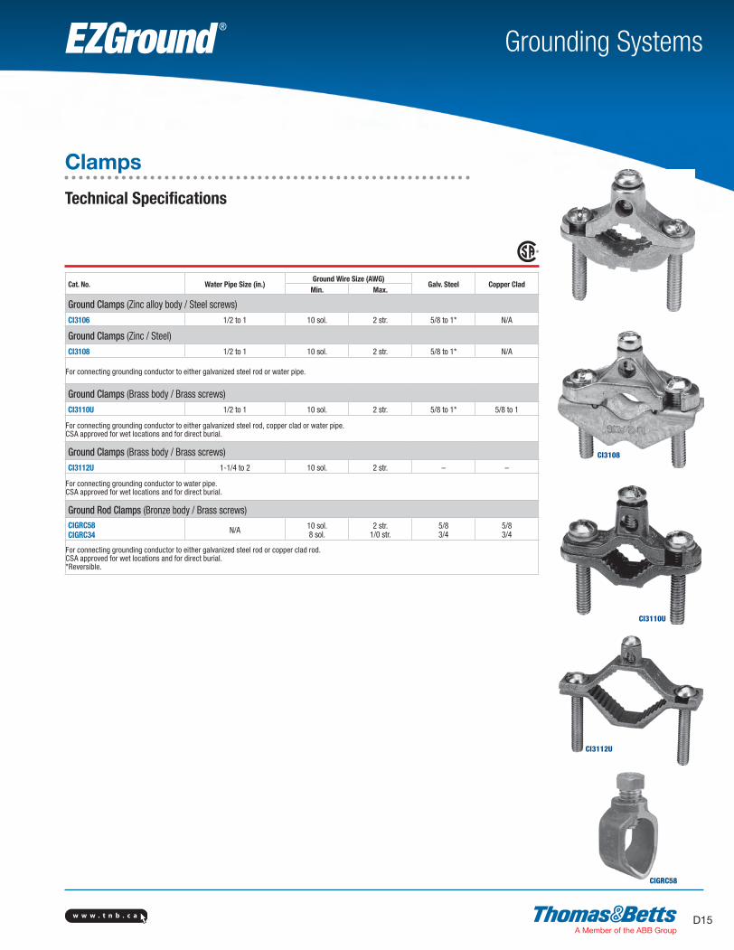
Technical Specifications
Cat. No. Water Pipe Size (in.)Ground Wire Size (AWG)
Galv. Steel Copper CladMin. Max.
Ground Clamps (Zinc alloy body / Steel screws)CI3106 1/2 to 1 10 sol. 2 str. 5/8 to 1* N/A
Ground Clamps (Zinc / Steel)CI3108 1/2 to 1 10 sol. 2 str. 5/8 to 1* N/A
For connecting grounding conductor to either galvanized steel rod or water pipe.
Ground Clamps (Brass body / Brass screws)CI3110U 1/2 to 1 10 sol. 2 str. 5/8 to 1* 5/8 to 1
For connecting grounding conductor to either galvanized steel rod, copper clad or water pipe.CSA approved for wet locations and for direct burial.
Ground Clamps (Brass body / Brass screws)CI3112U 1-1/4 to 2 10 sol. 2 str. – –
For connecting grounding conductor to water pipe.CSA approved for wet locations and for direct burial.
Ground Rod Clamps (Bronze body / Brass screws)CIGRC58CIGRC34 N/A 10 sol.
8 sol.2 str.
1/0 str.5/83/4
5/83/4
For connecting grounding conductor to either galvanized steel rod or copper clad rod.CSA approved for wet locations and for direct burial.*Reversible.
CI3106
CI3108
CI3110U
CI3112U
CIGRC58
SectionD-grounding-systems.indd 15 6/6/2017 9:43:11 AM
w w w . t n b . c aD16
Grounding SystemsEZGround ®
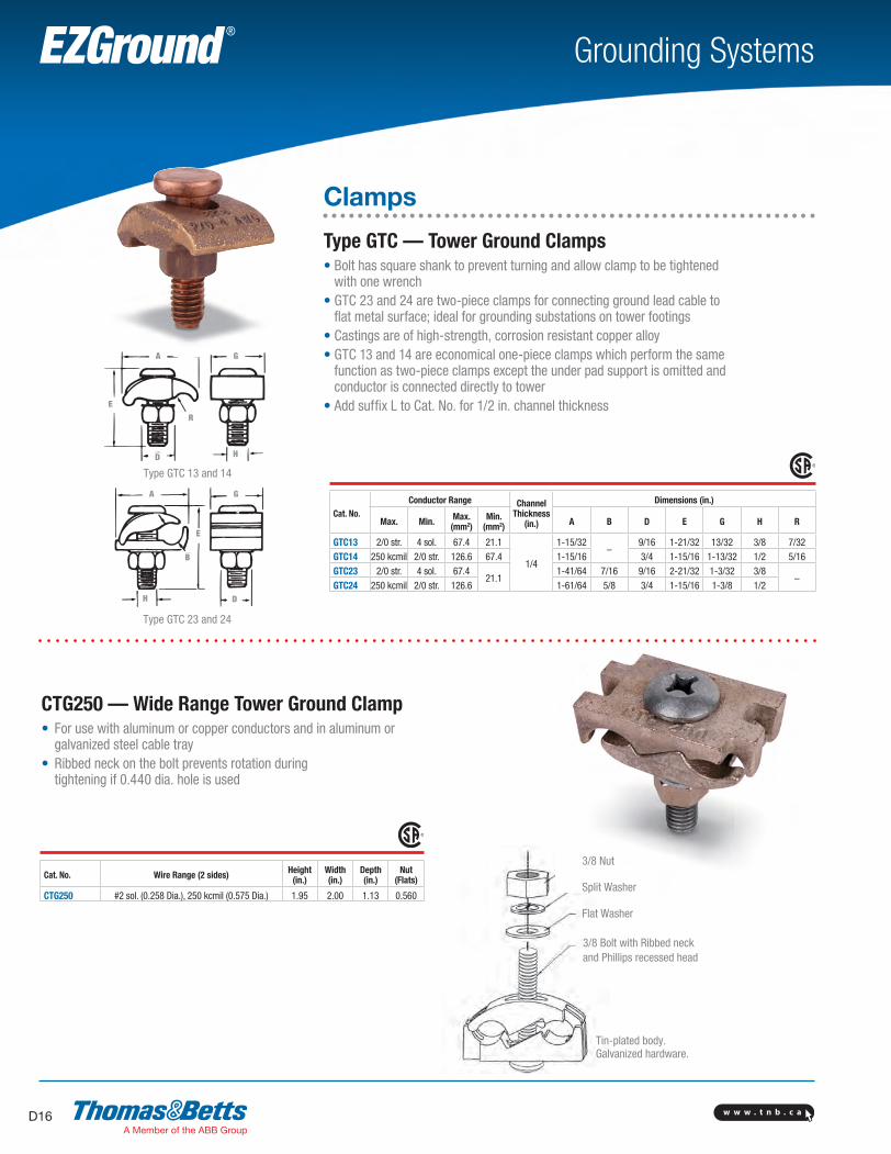
Clamps
Type GTC — Tower Ground Clamps• Bolt has square shank to prevent turning and allow clamp to be tightened
with one wrench• GTC 23 and 24 are two-piece clamps for connecting ground lead cable to
flat metal surface; ideal for grounding substations on tower footings• Castings are of high-strength, corrosion resistant copper alloy• GTC 13 and 14 are economical one-piece clamps which perform the same
function as two-piece clamps except the under pad support is omitted and conductor is connected directly to tower
• Add suffix L to Cat. No. for 1/2 in. channel thickness
Cat. No.Conductor Range Channel
Thickness (in.)
Dimensions (in.)
Max. Min. Max. (mm2)
Min. (mm2) A B D E G H R
GTC13 2/0 str. 4 sol. 67.4 21.1
1/4
1-15/32–
9/16 1-21/32 13/32 3/8 7/32GTC14 250 kcmil 2/0 str. 126.6 67.4 1-15/16 3/4 1-15/16 1-13/32 1/2 5/16GTC23 2/0 str. 4 sol. 67.4
21.11-41/64 7/16 9/16 2-21/32 1-3/32 3/8
–GTC24 250 kcmil 2/0 str. 126.6 1-61/64 5/8 3/4 1-15/16 1-3/8 1/2
Cat. No. Wire Range (2 sides) Height(in.)
Width(in.)
Depth(in.)
Nut (Flats)
CTG250 #2 sol. (0.258 Dia.), 250 kcmil (0.575 Dia.) 1.95 2.00 1.13 0.560
3/8 Nut
Split Washer
Flat Washer
Tin-plated body.Galvanized hardware.
Type GTC 13 and 14
Type GTC 23 and 24
CTG250 — Wide Range Tower Ground Clamp• For use with aluminum or copper conductors and in aluminum or galvanized steel cable tray• Ribbed neck on the bolt prevents rotation during tightening if 0.440 dia. hole is used
A G
E
R
D H
A G
E
D
B
H
3/8 Bolt with Ribbed neck and Phillips recessed head
SectionD-grounding-systems.indd 16 6/6/2017 9:43:12 AM

w w w . t n b . c a D17
Grounding SystemsEZGround ®
Clamps
I-Beam Ground ClampsConnect ground cable to I-Beam or any 1 in. maximum structural steel member — without welding or drilling• Breakaway bolt head shears at predetermined torque to ensure tight connection• Heavy-duty compression lug provides excellent current carrying capabilities• Surface of steel must be cleaned in accordance with installation
instruction sheet provided with product• Connector made of high-conductivity cast copper bright dip• Clamp made of drop-forged high-grade steel, zinc-plated
Cat. No. Wire Range TBM15I, TBM15 Installing Tool, Die Code
Die Cat. No.
IBG2-10 2 thru 1/0 AWG 66H 15534SS
IBG20-40 2/0 thru 4/0 AWG 76 15506SS
IBG350-500 350 kcmil thru 500 kcmil 115H 15504SSHydraulic tooling with hex crimp dies.Use 15500TB adaptor for TBM15-Ton Tool.
2
2
2
* Number of crimps.
Ground ClampsFor permanent, reliable connection• Crimp to cable• Clamp to ground rod and rebar• Use standard Color-Keyed® hand and hydraulic tools• Colour-coded for easy installation die selection• Made from high-conductivity wrought copper• Furnished with stainless steel hardware, 1/4 in. washers, bolts and nuts
Cat. No. Wire Size Ground Rod Diameter (in.) Rebar (in.) Bolt Size (in.) Die Code
and Colour
CC2C-45R #2–#3 AWG1/2 or 5/8 0.80 0.25
33 Brown
CC1C-45R #1 AWG 37 Green
CC10C-56R 1/0 AWG5/8 or 3/4 0.83 0.38
42 Pink
CC20C-56R 2/0 AWG 45 Black
CC40C-56R 4/0 AWG 54 PurpleUL Approved for direct burial.
DB
SectionD-grounding-systems.indd 17 6/6/2017 9:43:13 AM
w w w . t n b . c aD18
Grounding SystemsEZGround ®
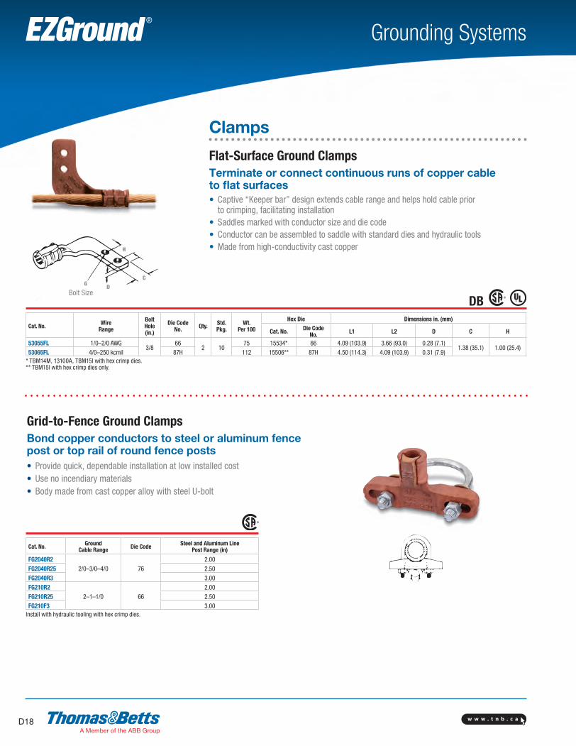
Cat. No. Wire Range
Bolt Hole (in.)
Die Code No. Qty. Std.
Pkg.Wt.
Per 100
Hex Die Dimensions in. (mm)
Cat. No. Die Code No. L1 L2 D C H
53055FL 1/0–2/0 AWG3/8
662 10
75 15534* 66 4.09 (103.9) 3.66 (93.0) 0.28 (7.1)1.38 (35.1) 1.00 (25.4)
53065FL 4/0–250 kcmil 87H 112 15506** 87H 4.50 (114.3) 4.09 (103.9) 0.31 (7.9)* TBM14M, 13100A, TBM15I with hex crimp dies. ** TBM15I with hex crimp dies only.
Grid-to-Fence Ground ClampsBond copper conductors to steel or aluminum fence post or top rail of round fence posts• Provide quick, dependable installation at low installed cost• Use no incendiary materials• Body made from cast copper alloy with steel U-bolt
Cat. No. Ground Cable Range Die Code Steel and Aluminum Line
Post Range (in)
FG2040R22/0–3/0–4/0 76
2.00FG2040R25 2.50FG2040R3 3.00FG210R2
2–1–1/0 662.00
FG210R25 2.50FG210F3 3.00
Install with hydraulic tooling with hex crimp dies.
Clamps
Flat-Surface Ground ClampsTerminate or connect continuous runs of copper cable to flat surfaces• Captive “Keeper bar” design extends cable range and helps hold cable prior to crimping, facilitating installation• Saddles marked with conductor size and die code• Conductor can be assembled to saddle with standard dies and hydraulic tools• Made from high-conductivity cast copper
DB
C
H
GBolt size
D
C
H
GBolt size
DBolt Size
H
G D
C
SectionD-grounding-systems.indd 18 6/6/2017 9:43:14 AM
w w w . t n b . c a D19
Grounding SystemsEZGround ®
Service Post Connectors
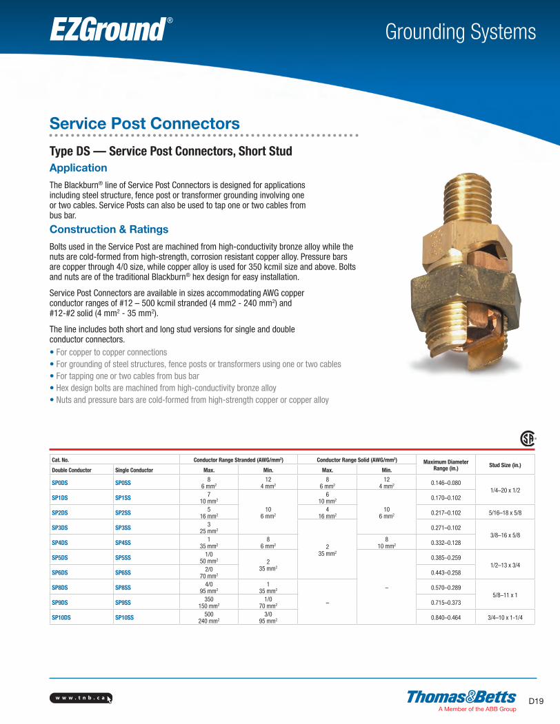
Type DS — Service Post Connectors, Short StudApplication
The Blackburn® line of Service Post Connectors is designed for applications including steel structure, fence post or transformer grounding involving one or two cables. Service Posts can also be used to tap one or two cables from bus bar.
Construction & Ratings
Bolts used in the Service Post are machined from high-conductivity bronze alloy while the nuts are cold-formed from high-strength, corrosion resistant copper alloy. Pressure bars are copper through 4/0 size, while copper alloy is used for 350 kcmil size and above. Bolts and nuts are of the traditional Blackburn® hex design for easy installation.
Service Post Connectors are available in sizes accommodating AWG copper conductor ranges of #12 – 500 kcmil stranded (4 mm2 - 240 mm2) and #12-#2 solid (4 mm2 - 35 mm2).
The line includes both short and long stud versions for single and double conductor connectors.• For copper to copper connections• For grounding of steel structures, fence posts or transformers using one or two cables• For tapping one or two cables from bus bar• Hex design bolts are machined from high-conductivity bronze alloy• Nuts and pressure bars are cold-formed from high-strength copper or copper alloy
Cat. No. Conductor Range Stranded (AWG/mm2) Conductor Range Solid (AWG/mm2) Maximum DiameterRange (in.) Stud Size (in.)
Double Conductor Single Conductor Max. Min. Max. Min.
SP0DS SP0SS 86 mm2
124 mm2
86 mm2
124 mm2 0.146–0.080
1/4–20 x 1/2SP1DS SP1SS 7
10 mm2
106 mm2
610 mm2
106 mm2
0.170–0.102
SP2DS SP2SS 516 mm2
416 mm2 0.217–0.102 5/16–18 x 5/8
SP3DS SP3SS 325 mm2
235 mm2
0.271–0.1023/8–16 x 5/8
SP4DS SP4SS 135 mm2
86 mm2
810 mm2 0.332–0.128
SP5DS SP5SS 1/050 mm2 2
35 mm2
–
0.385–0.2591/2–13 x 3/4
SP6DS SP6SS 2/070 mm2 0.443–0.258
SP8DS SP8SS 4/095 mm2
135 mm2
–
0.570–0.2895/8–11 x 1
SP9DS SP9SS 350150 mm2
1/070 mm2 0.715–0.373
SP10DS SP10SS 500240 mm2
3/095 mm2 0.840–0.464 3/4–10 x 1-1/4
SectionD-grounding-systems.indd 19 6/6/2017 9:43:14 AM
w w w . t n b . c aD20
Grounding SystemsEZGround ®
Service Post Connectors
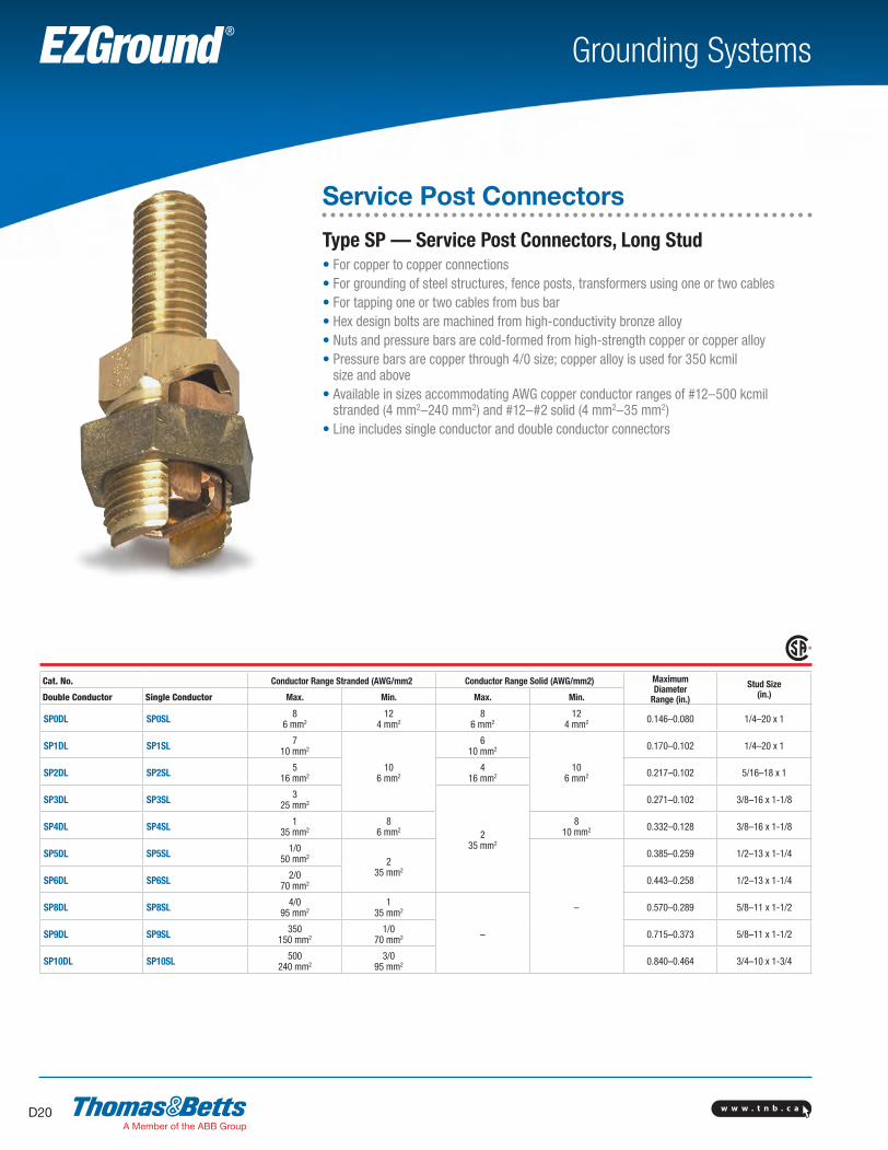
Type SP — Service Post Connectors, Long Stud• For copper to copper connections• For grounding of steel structures, fence posts, transformers using one or two cables• For tapping one or two cables from bus bar• Hex design bolts are machined from high-conductivity bronze alloy• Nuts and pressure bars are cold-formed from high-strength copper or copper alloy• Pressure bars are copper through 4/0 size; copper alloy is used for 350 kcmil
size and above• Available in sizes accommodating AWG copper conductor ranges of #12–500 kcmil
stranded (4 mm2–240 mm2) and #12–#2 solid (4 mm2–35 mm2)• Line includes single conductor and double conductor connectors
Cat. No. Conductor Range Stranded (AWG/mm2 Conductor Range Solid (AWG/mm2) MaximumDiameter
Range (in.)
Stud Size(in.)Double Conductor Single Conductor Max. Min. Max. Min.
SP0DL SP0SL 86 mm2
124 mm2
86 mm2
124 mm2 0.146–0.080 1/4–20 x 1
SP1DL SP1SL 710 mm2
106 mm2
610 mm2
106 mm2
0.170–0.102 1/4–20 x 1
SP2DL SP2SL 516 mm2
416 mm2 0.217–0.102 5/16–18 x 1
SP3DL SP3SL 325 mm2
235 mm2
0.271–0.102 3/8–16 x 1-1/8
SP4DL SP4SL 135 mm2
86 mm2
810 mm2 0.332–0.128 3/8–16 x 1-1/8
SP5DL SP5SL 1/050 mm2
235 mm2
–
0.385–0.259 1/2–13 x 1-1/4
SP6DL SP6SL 2/070 mm2 0.443–0.258 1/2–13 x 1-1/4
SP8DL SP8SL 4/095 mm2
135 mm2
–
0.570–0.289 5/8–11 x 1-1/2
SP9DL SP9SL 350150 mm2
1/070 mm2 0.715–0.373 5/8–11 x 1-1/2
SP10DL SP10SL 500240 mm2
3/095 mm2 0.840–0.464 3/4–10 x 1-3/4
SectionD-grounding-systems.indd 20 6/6/2017 9:43:15 AM
w w w . t n b . c a D21
Grounding SystemsEZGround ®
Transformer Tank Ground Connectors
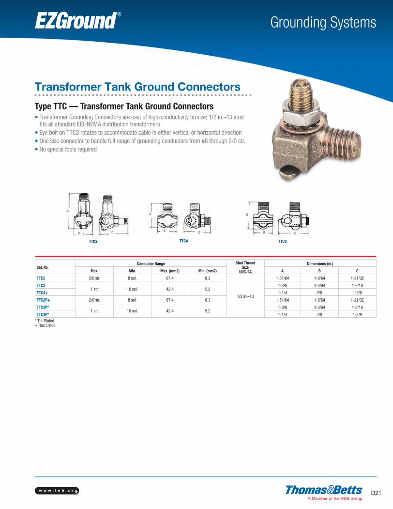
Type TTC — Transformer Tank Ground Connectors• Transformer Grounding Connectors are cast of high-conductivity bronze; 1/2 in.–13 stud
fits all standard EEI-NEMA distribution transformers• Eye bolt on TTC2 rotates to accommodate cable in either vertical or horizontal direction• One size connector to handle full range of grounding conductors from #8 through 2/0 str.• No special tools required
Cat. No.Conductor Range Stud Thread
SizeUNC-2A
Dimensions (in.)
Max. Min. Max. (mm2) Min. (mm2) A B C
TTC2 2/0 str. 8 sol. 67.4 8.3
1/2 in.–13
1-51/64 1-9/64 1-21/32
TTC31 str. 10 sol. 42.4 5.2
1-3/8 1-3/64 1-9/16
TTC4+ 1-1/4 7/8 1-3/8
TTC2P+ 2/0 str. 8 sol. 67.4 8.3 1-51/64 1-9/64 1-21/32
TTC3P*1 str. 10 sol. 42.4 5.2
1-3/8 1-3/64 1-9/16
TTC4P* 1-1/4 7/8 1-3/8* Tin-Plated.+ Rus Listed.
TTC2 TTC4 TTC3
AA
CBB C CB
A
SectionD-grounding-systems.indd 21 6/6/2017 9:43:16 AM
w w w . t n b . c aD22
Grounding SystemsEZGround ®
Conduit Hubs
Cat. No. Ground Wire Size (AWG) Conduit/Wire Size
3930#8 to #2
1/2 in. Conduit3940 3/4 in. Conduit3950 #8 to #3/0 1 Conduit3951 #8 to #4/0 1-1/4 in. Conduit3960 #8 to #4 Armored Wire
Material: Malleable iron.
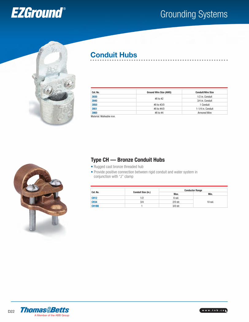
Type CH — Bronze Conduit Hubs• Rugged cast bronze threaded hub• Provide positive connection between rigid conduit and water system in
conjunction with “J” clamp
Cat. No. Conduit Size (in.)Conductor Range
Max. Min.
CH12 1/2 6 sol.10 sol.CH34 3/4 2/0 str.
CH1BB 1 3/0 str.
SectionD-grounding-systems.indd 22 6/6/2017 9:43:17 AM

w w w . t n b . c a D23
Grounding SystemsEZGround ®
Lay-In Lug Connectors
Cat. No.
Conductor Range Stud Size Dimensions
AWG mm2 in. mmH W L
in. mm in. mm in. mm
CULL4144-14 16-1.5 0.22 5.59 0.78 19.81 0.38
9.651.07 27.18
CULL414TP* 9.65* Tin-plated.90°C Rating.
Blackburn® Lay-In Lug
Cat. No.Conductor Range AWG Stud Size
in. mm2 in. mm2
LL414 4–14 16–1.5 0.22 5.59
LL1014 1/0–14 50–1.5 0.27 6.86
LL306 3/0–6 70–160.33 8.38
LL2506 250–6 120–16These grounding connectors are dual rated for aluminum and copper conductors.The opened face design allows the installer to quickly lay-in the grounding conductor as a jumper.
W
H
DB
Copper Lay-In Lug Connectors• Ideal for swimming pool grounding applications• Carries “DB” marking for direct burial• Open-faced design enables installer to quickly lay-in grounding
conductor as jumper to multiple conduits with no break in ground conductor
Cat. No. Range Torque
MLG25020 250 kcmil through 2/0 stranded 40 feet/pounds
Mechanical Lay–in Ground ConnectorStep 1• Open grounding connector by loosening bolts• Swing top and center clamps to the side to
expose lower conductor grooves.
Step 2• Lay-in first conductor into lower conductor
groove
Step 3• Rotate center clamp into position over first
conductor
Step 4• Lay-in second conductor into center clamp
conductor groove (parallel conductor style is shown)
Step 5• When conductors are in place, rotate top clamp over
the second conductor and torque bolts to 40 - 45 ft-lb. (cross conductor style is shown)
Loosenbolts
Top clamp
Swing open
Center clampSwing open
Lower conductor grooves
Lower conductor grooves
First conductor
Lower conductor grooves
First conductor
Rotate
First conductor
Second conductor
RotateTopClamp
Torque Bolts to 40 – 45 ft–lb.
SectionD-grounding-systems.indd 23 6/6/2017 9:43:21 AM
w w w . t n b . c aD24
Grounding SystemsEZGround ®
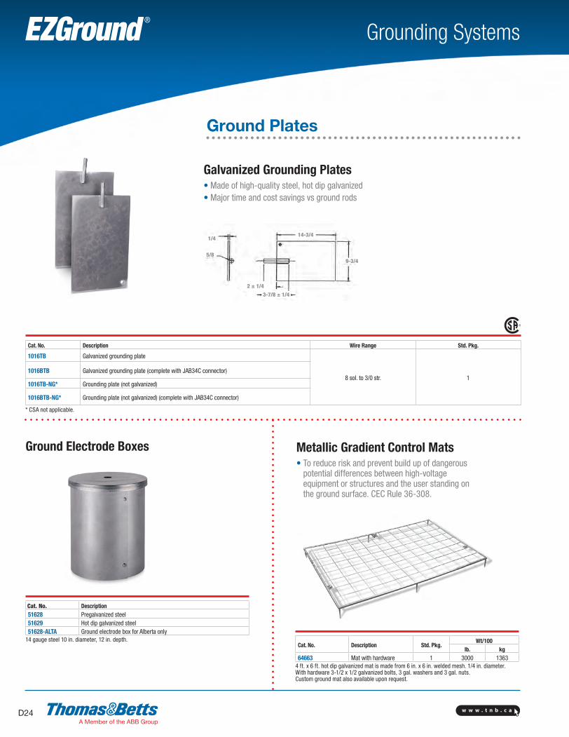
Ground Plates
1/4
5/8
3-7/8 ± 1/4
14-3/4
9-3/4
Galvanized Grounding Plates• Made of high-quality steel, hot dip galvanized• Major time and cost savings vs ground rods
Cat. No. Description Wire Range Std. Pkg.
1016TB Galvanized grounding plate
8 sol. to 3/0 str. 11016BTB Galvanized grounding plate (complete with JAB34C connector)
1016TB-NG* Grounding plate (not galvanized)
1016BTB-NG* Grounding plate (not galvanized) (complete with JAB34C connector)
* CSA not applicable.
Cat. No. Description51628 Pregalvanized steel51629 Hot dip galvanized steel51628-ALTA Ground electrode box for Alberta only
14 gauge steel 10 in. diameter, 12 in. depth.
Metallic Gradient Control Mats• To reduce risk and prevent build up of dangerous
potential differences between high-voltage equipment or structures and the user standing on the ground surface. CEC Rule 36-308.
Cat. No. Description Std. Pkg.Wt/100
lb. kg64663 Mat with hardware 1 3000 1363
4 ft. x 6 ft. hot dip galvanized mat is made from 6 in. x 6 in. welded mesh. 1/4 in. diameter. With hardware 3-1/2 x 1/2 galvanized bolts, 3 gal. washers and 3 gal. nuts.Custom ground mat also available upon request.
2 ± 1/4
Ground Electrode Boxes
SectionD-grounding-systems.indd 24 6/6/2017 9:43:23 AM
w w w . t n b . c a D25
Grounding SystemsEZGround ®
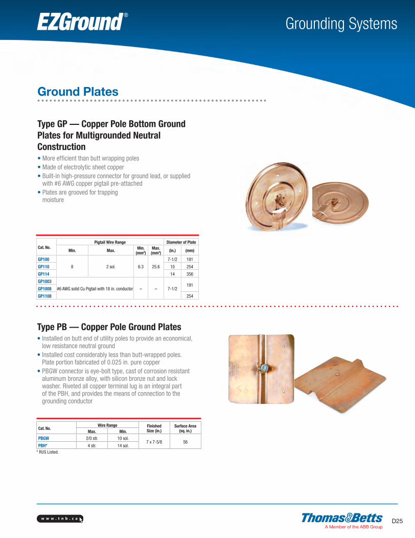
Cat. No.Pigtail Wire Range Diameter of Plate
Min. Max. Min. (mm2)
Max. (mm2) (in.) (mm)
GP100
8 2 sol. 6.3 25.6
7-1/2 191
GP110 10 254
GP114 14 356
GP1003
#6 AWG solid Cu Pigtail with 18 in. conductor – – 7-1/2191
GP1008
GP1108 254
Type GP — Copper Pole Bottom Ground Plates for Multigrounded Neutral Construction• More efficient than butt wrapping poles• Made of electrolytic sheet copper• Built-in high-pressure connector for ground lead, or supplied
with #6 AWG copper pigtail pre-attached• Plates are grooved for trapping
moisture
Type PB — Copper Pole Ground Plates• Installed on butt end of utility poles to provide an economical,
low resistance neutral ground• Installed cost considerably less than butt-wrapped poles.
Plate portion fabricated of 0.025 in. pure copper• PBGW connector is eye-bolt type, cast of corrosion resistant
aluminum bronze alloy, with silicon bronze nut and lock washer. Riveted all copper terminal lug is an integral part of the PBH, and provides the means of connection to the grounding conductor
Cat. No.Wire Range Finished
Size (in.)Surface Area
(sq. in.)Max. Min.
PBGW 2/0 str. 10 sol.7 x 7-5/8 56
PBH* 4 str. 14 sol.* RUS Listed.
Ground Plates
SectionD-grounding-systems.indd 25 6/6/2017 9:43:24 AM
w w w . t n b . c aD26
Grounding SystemsEZGround ®
Tap
Main
T
H
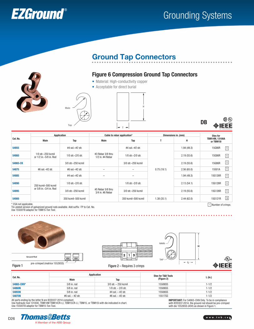
Ground Tap Connectors
Cat. No.Application Cable to rebar application* Dimensions in. (mm) Dies for
TBM14M, 13100A or TBM15IMain Tap Main Tap T H
54855
1/0 str.–250 kcmil or 1/2 in.–5/8 in. Rod
#4 sol.–#2 str.
#3 Rebar 3/8 thru 1/2 in. #4 Rebar
#4 sol.–#2 str.
0.75 (19.1)
1.94 (49.3) 15G86R
54860 1/0 str.–2/0 str. 1/0 str.–2/0 str. 2.19 (55.6) 15G86R
54865-CK 3/0 str.–250 kcmil 3/0 str.–250 kcmil 2.19 (55.6) 15G86R
54875 #6 sol.–#2 str. #6 sol.–#2 str. – – 2.56 (65.0) 15501A
54885
250 kcmil–500 kcmil or 5/8 in.–3/4 in. Rod
#4 sol.–#2 str. – – 1.94 (49.3) 15G126R
54890 1/0 str.–2/0 str.
#5 Rebar 5/8 thru3/4 in. #6 Rebar
1/0 str.–2/0 str. 2.13 (54.1) 15G126R
54895 3/0 str.–250 kcmil 3/0 str.–250 kcmil 2.19 (55.6) 15G126R
54900 350 kcmil–500 kcmil 350 kcmil–500 kcmil 1.38 (35.1) 2.44 (62.0) 15G121R
* CSA not applicable. Tin-plated version of galvanized ground rods available. Add suffix -TP to Cat. No.Use 15500TB adaptor for TBM15-Ton Tool.
1
1
1
1
1
1
1
3
* Number of crimps.
Main
T
H
TapDB
Figure 6 Compression Ground Tap Connectors• Material: High-conductivity copper• Acceptable for direct burial
Tap
Main
T
H
Cat. No.Application Dies for T&B Tools
(Figure 2) L (in.)Main Tap
54865-CKN* 5/8 in. rod 3/0 str. – 250 kcmil 15506SS 1-1/254860N 5/8 in. rod 1/0 str. – 2/0 str. 15506SS 1-1/254855N 5/8 in. rod #4 sol. – #2 str. 15506SS 1-1/254875N #6 sol. – #2 str. #6 sol. – #2 str. 15517SS 1-1/2
All parts ending by the letter N are IEEE837-2014 compliant.Use hydraulic tool 13100A, TBM14M TBM14CR-LI, TBM15CR-LI, TBM15, or TBM15I with die indicated in chart.Use 15500TB adaptor for TBM15-Ton Tool.
Figure 2 – Requires 3 crimps
IMPORTANT: For 54865-CKN Only. To be in compliance with IEEE837-2014, the ground rod should be pre-crimped with die 15526SS (45H) as shown in Figure 1.
Figure 1pre-crimped (matrice 15526SS)
837-2014 REQUIREMENTS
w w w . t n b . c a D27
Grounding SystemsEZGround ®
T
H
A
B
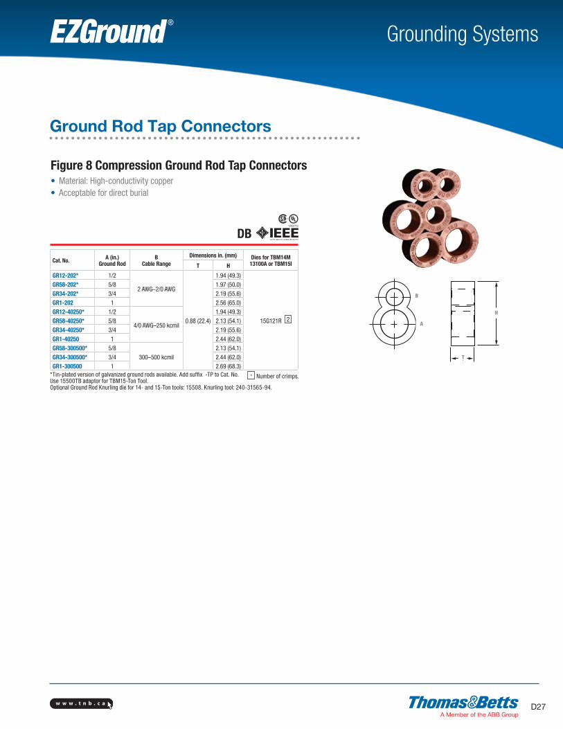
Ground Rod Tap Connectors
Figure 8 Compression Ground Rod Tap Connectors• Material: High-conductivity copper• Acceptable for direct burial
Cat. No. A (in.) Ground Rod
B Cable Range
Dimensions in. (mm) Dies for TBM14M 13100A or TBM15IT H
GR12-202* 1/2
2 AWG–2/0 AWG
0.88 (22.4)
1.94 (49.3)
15G121R
GR58-202* 5/8 1.97 (50.0)GR34-202* 3/4 2.19 (55.6)GR1-202 1 2.56 (65.0)GR12-40250* 1/2
4/0 AWG–250 kcmil
1.94 (49.3)GR58-40250* 5/8 2.13 (54.1)GR34-40250* 3/4 2.19 (55.6)GR1-40250 1 2.44 (62.0)GR58-300500* 5/8
300–500 kcmil2.13 (54.1)
GR34-300500* 3/4 2.44 (62.0)GR1-300500 1 2.69 (68.3)
*Tin-plated version of galvanized ground rods available. Add suffix -TP to Cat. No.Use 15500TB adaptor for TBM15-Ton Tool.Optional Ground Rod Knurling die for 14- and 15-Ton tools: 15508. Knurling tool: 240-31565-94.
2
* Number of crimps.
H
B
A
T
DB

w w w . t n b . c aD28
Grounding SystemsEZGround ®
Element A
Element B
LT
L D
TTT-T
Element A
Element B
LT
L D
TT
Ground Rod to Grid Connectors and Ground Grid Connectors
Cat. No. A in. (mm)Ground Rod
B Cable Range
Dimensions in. (mm) Dies for TBM14M, 13100A or TBM15ID L Element A Element B
54855LR12*1/2 (12.7)
2 AWG–250 kcmil
0.31 (7.8) 2.50 (63.5)
15G121R
15G86R
54885LR12* 250 kcmil–500 kcmil 15G126R
54865LR58*5/8 (16.0)
2 AWG–250 kcmil 15G86R
54895LR58* 250 kcmil–500 kcmil 15G126R
54875LR34*3/4 (19.1)
2 AWG–250 kcmil
0.50 (12.7) 2.63 (66.8)
15G86R
54900LR34* 250 kcmil–500 kcmil 15G126R
54910LR1001 (25.4)
2 AWG–250 kcmil 15G86R
54920LR100 250 kcmil–500 kcmil 15G126R*Tin-plated version available for galvanized ground rods. Add suffix -TP to Cat. No.
Figure 6 to 6 Compression Ground Grid Connectors• Material: High-conductivity copper• Acceptable for direct burial
Cat. No. ACable Range
Bto Cable Range
Bto Ground Rod
Bto Rebar D (in.) T (in.)
Dies for T&B Tool*
A B54900L 250 kcmil–500 kcmil 250 kcmil–500 kcmil 5/8 in.–3/4 in. rod #5-#6 (5/8 in.–3/4 in.) 3/4 1-1/8 15G121R 15G121R
54895L #2 str.–250 kcmil 250 kcmil–500 kcmil 5/8 in.–3/4 in. rod #5-#6 (5/8 in.–3/4 in.) 1/2 3/4 15G86R 15G126R
54885L #6 sol.–#2 str. 250 kcmil–500 kcmil 5/8 in.–3/4 in. rod #5-#6 (5/8 in.–3/4 in.) 5/8 3/4 15501A 15G126R
54875L #2 str.–250 kcmil #2 str.–250 kcmil 1/2 in.–5/8 in. rod #3-#4 (3/8 in.–1/2 in.) 1/2 3/4 15G86R 15G86R
54865L #6 sol.–#2 str. #1 str.–250 kcmil 1/2 in.–5/8 in. rod #3-#4 (3/8 in.–1/2 in.) 5/16 3/4 15501A 15G86R
54855L #6 sol.–#2 str. #6 sol.–#2 str. – – 5/16 3/4 15501A 15501A
*Use hydraulic tool 13100A, TBM14CR-LI, TBM14M, TBM15CR-LI, TBM15, or TBM15I or with die marked on cat. no.Use 15500TB adaptor for 15-Ton Tool TBM15I.
3 3
Figure 6 to 8 Compression Ground Rod to Grid Connectors
DL
7/8 in.
L3/4 in.
Element B
A
DB
DB
Element A
B
TD
T
2-1/2 in.
2-1/2 in.
1 1
1 1
1 11 1
1 1
* Number of crimps.

w w w . t n b . c a D29
Grounding SystemsEZGround ®
Cable-to-Cable or Cable-to-Rod Connectors
One-piece construction for cable-to-cable, cable-to-rod, “T” and “X” connections• Suitable for direct burial or in concrete• Replaces exothermic welds• Made from high-conductivity wrought copper
Cat. No.Cable to Cable Range Rod to Cable range
Main Die Code
TBM14 and 15 Die Cat. No. Branch Die
CodeTBM14 and 15
Die Cat. No.Ground Rod
(in.)Die
CodeTBM14 and 15
Die Cat. No. Cable Die Code
TBM14 and 15 Die Cat. No.
GG21-21 #2 or #1 45 15526SS #2 or #1 45 15526SS
– – – – – –
GG10-10 1/0 54 15511SS 1/0 54 15511SS
GG2030-21
2/0 or 3/0 60 15532SS
#2 or #1 50–45 15526SS15530SS
GG2030-10 1/0 54H 15511SS
GG2030-2030 2/0–3/0 60 15532SS
GG40250-21
4/0 or250 kcmil 71H 15514SS
#2 45 50
15526SS15530SS
1/25/8
7180H
15514SS15517SS
#2 or #1#2 or #1
4550
15526SS15530SS
GG40250-10 1/0 kcmil 54H 15511SS 1/0 54 15511SS
GG40250-2030 2/0 or 3/0 60 15532SS 2/0 or 3/02/0 or 3/0
6060
15532SS15532SS
GG40250-40250 4/0 or 250 kcmil 71H 15514SS 4/0 or 250
4/0 or 2504/0 or 250
71H71H71H
15514SS15514SS
GG500-40250
500 kcmil 87H15506SS
4/0 or 250 kcmil 71H 15514SS
3/45/8 87H
15506SSGG500-500 500 kcmil 87H 15506SS 500 87H
15506SSGG500-350 350 kcmil 80H 15606SS 350 80H
GG500-2030 2/0 or 3/0 60 15532SS–
2/0 or 3/0 60 15532SS
GG350-350 350 kcmil 80H 350 kcmil 80H 15606SS – – – – –Uses 15500TB adaptor for 15-Ton Tools. Optional ground rod knurling die or TBM14 and 15 tools: 15508SS. Optional ground rod knurling tool: 240-31565-94.
2
2
2
2
2
2
2
2
2
2
2
2
2
2
* Number of crimps.
2
2
2
2
2
DB
SectionD-grounding-systems.indd 29 6/6/2017 9:43:28 AM
w w w . t n b . c aD30
Grounding SystemsEZGround ®
L1 Nom.L1 Nom.
L2 Nom.
DB
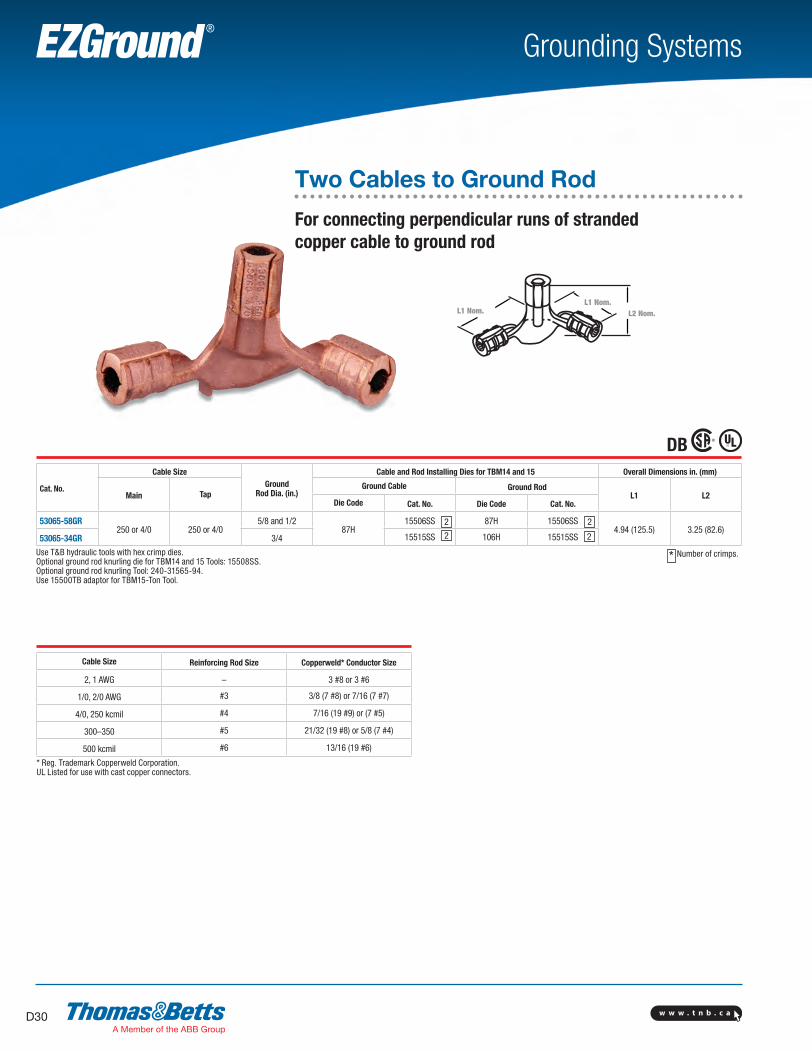
Cat. No.
Cable SizeGround
Rod Dia. (in.)
Cable and Rod Installing Dies for TBM14 and 15 Overall Dimensions in. (mm)
Main TapGround Cable Ground Rod
L1 L2Die Code Cat. No. Die Code Cat. No.
53065-58GR250 or 4/0 250 or 4/0
5/8 and 1/287H
15506SS 87H 15506SS4.94 (125.5) 3.25 (82.6)
53065-34GR 3/4 15515SS 106H 15515SS
Use T&B hydraulic tools with hex crimp dies.Optional ground rod knurling die for TBM14 and 15 Tools: 15508SS.Optional ground rod knurling Tool: 240-31565-94.Use 15500TB adaptor for TBM15-Ton Tool.
* Number of crimps.
2
2
2
2
Cable Size Reinforcing Rod Size Copperweld* Conductor Size
2, 1 AWG – 3 #8 or 3 #6
1/0, 2/0 AWG #3 3/8 (7 #8) or 7/16 (7 #7)
4/0, 250 kcmil #4 7/16 (19 #9) or (7 #5)
300–350 #5 21/32 (19 #8) or 5/8 (7 #4)
500 kcmil #6 13/16 (19 #6)
* Reg. Trademark Copperweld Corporation.UL Listed for use with cast copper connectors.
Two Cables to Ground Rod
For connecting perpendicular runs of stranded copper cable to ground rod
L1 Nom.L1 Nom.
L2 Nom.
SectionD-grounding-systems.indd 30 6/6/2017 9:43:29 AM

w w w . t n b . c a D31
Grounding SystemsEZGround ®
L1 Nom.L2 Nom.
53055
53065
DB
Cat. No.Rod to Cable Range Cable to Cable Range Rod Cable and Rod Installing Dies for TBM14 and 15 Overall Dimensions in. (mm)
Rod Size (in.) Cable Range Main Branch Die Code Cat. No. Die Code Cat. No. L1 L2
53055 – – 1/0–2/0 AWG 1/0–2/0 AWG – – 66 15534SS 3.88 (98.6) 3.88 (98.6)
53059*
1/2–5/8
2–1 AWG
4/0–250 kcmil
2–1 AWG
87H 15506SS
54H 15511SS 4.16 (105.7) 4.56 (115.8)
53060* 1/0–2/0 AWG 1/0–2/0 AWG 87H15506SS 4.44 (112.8) 4.44 (112.8)
53065* 4/0–250 kcmil 4/0–250 kcmil 87H
53069* 3/4 1/0–2/0 AWG300–350 kcmil
1/0–2/0 AWG106H 15515SS
66 15534SS 4.59 (116.6) 4.59 (116.6)
53071* 4/0–250 kcmil 4/0–250 kcmil 106H 15515SS 5.25 (133.4) 4.78 (121.4)
53073* 1 1/0–2/0 AWG
500 kcmil
1/0–2/0 AWG
125H 15603
66 15534SS 4.81 (122.2) 4.88 (124.0)
53075* 4/0–250 kcmil 4/0–250 kcmil 87H 15506SS 6.56 (166.6) 5.00 (127.0)
53080* 500 kcmil 500 kcmil 125H 15603 5.19 (131.8) 5.19 (131.8)
* 4/0–250 wire barrels suitable for 1/2 in. and 5/8 rod, 300–500 kcmil wire barrels suitable for 3/4 in. rods, 500 kcmil wire barrels suitable for 1 rods.** Do not meet IEEE837.Cat. No. 15500TB adaptor is required for all 15500SS Series dies, not for 15600SS Series, crimp with 15-Ton tools.Hydraulic tools only.
* Number of crimps.
Grounding Grid Connectors
Heavy-Duty Cast Copper**L1 Nom.
L2 Nom.
53055
53065
2
1
2
2
1
2
1
2
3 2
3
SectionD-grounding-systems.indd 31 6/6/2017 9:43:29 AM
w w w . t n b . c aD32
Grounding SystemsEZGround ®
H
L††
L
H
L
H
C-Taps
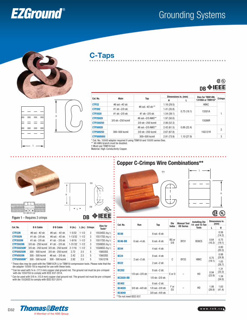
Cat. No. Run Tap Die Index
Manual ToolOD Series
Installing Die 14- and 15-Ton
Tools
Dimensions in. (mm)
L H
BC48
6 sol.–4 str.
8 sol.–8 str.
BG or 5/8 BY31 B58CS 0.64
(16.3)
0.56 (14.2)
BC46-BB 6 sol.–6 str. 0.75 (19.1)
BC44 4 sol.–4 str. 0.80 (20.3)
BC242 sol.–2 str.
8 sol.–4 str.C BY33 HBKC 0.75
(19.1)
0.98 (24.9)
BC22 2 sol.–2 str. 1.05 (26.7)
BC2021/0 sol.–2/0 str.
8 sol.–2 str.E or O – HO 0.94
(23.9)
1.31 (33.3)
BC2020-BB 1/0 str.–2/0 str. 1.34 (34.0)
BC402
3/0 str.–4/0 str.
6 sol.–2 str.F orD3
– HD 1.06 (26.9)
1.63 (41.4)BC4020 1/0 sol.–2/0 str.
BC4040 3/0 sol.–4/0 str.**Do not meet IEEE 837.
Cat. No. Main TapDimensions in. (mm) Dies for TBM14M,
13100A or TBM15I* CrimpsH L
CTP22 #6 sol.–#2 str.#6 sol.–#2 str.**
1.16 (29.5)
0.75 (19.1)
HBKC
1
CTP202 #1 str.–2/0 str. 1.41 (35.8)15501A
CTP2020 #1 str.–2/0 str. #1 str.–2/0 str. 1.54 (39.1)
CTP250203/0 str.–250 kcmil
#6 sol.–2/0 AWG** 1.97 (50.0)15G86R
CTP250250 3/0 str.–250 kcmil 2.06 (52.3)
0.88 (22.4)CTP50020
300–500 kcmil
#6 sol.–2/0 AWG** 2.42 (61.5)
15G121R2
CTP500250 3/0 str.–250 kcmil 2.67 (67.8)
CTP500500† 300–500 kcmil 2.91 (73.9) 1.10 (27.9) 3* Cat. No. 15500 adaptor required if using TBM15I and 155XX series Dies.** #6 AWG branch must be doubled.† Must use TBM15I toolMaterial: High-Conductivity Copper.
Copper C-Crimps Wire Combinations**
H
L
DB
L
H
Cat. No. Ø A Cable Ø B Cable H (in.) L (in.) Crimps Dies for Tools*
CTP22N #6 sol.- #2 str. #6 sol. - #2 str. 1-5/32 1-1/2 3 15534SS (Fig.1)
CTP202N #1 str.- 2/0 str. #6 sol. - #2 str. 1-13/32 1-1/2 3 15517SS (Fig.1)
CTP2020N #1 str.- 2/0 str. #1 str. - 2/0 str. 1-9/16 1-1/2 3 15517SS (Fig.1)
CTP25020N 3/0 str.- 250 kcmil #1 str. - 2/0 str. 1-31/32 1-1/2 3 15506SS (Fig.1)
CTP250250N† 3/0 str.- 250 kcmil 3/0 str.- 250 kcmil 2-1/16 1-1/2 3 15506SS (Fig.1)
CTP500250N 300 - 500 kcmil 3/0 str.- 250 kcmil 2.72 2.5 5 15603SSCTP50020N 300 - 500 kcmil #6 sol. - 2/0 str. 2.42 2.5 5 15603SSCTP500500N** 300 - 500 kcmil 300 - 500 kcmil 2.92 2.5 5 15G121N
Figure 1 – Requires 3 crimps
* These dies may be used with the TBM15CR-LI or TBM15I compression tools. Please note that the die adapter 15500-TB is required for use with these tools.
** Can be used with ¾ in. (17.3 mm) copper clad ground rod. The ground rod must be pre-crimped with die 15507SS to comply with IEEE 837-2014.
† Can be used with 5/8 in. (15.8 mm) copper clad ground rod. The ground rod must be pre-crimped with die 15526SS to comply with IEEE 837-2014.
H
L††
H
L
ØB
ØA
H
L
w w w . t n b . c a D33
Grounding SystemsEZGround ®
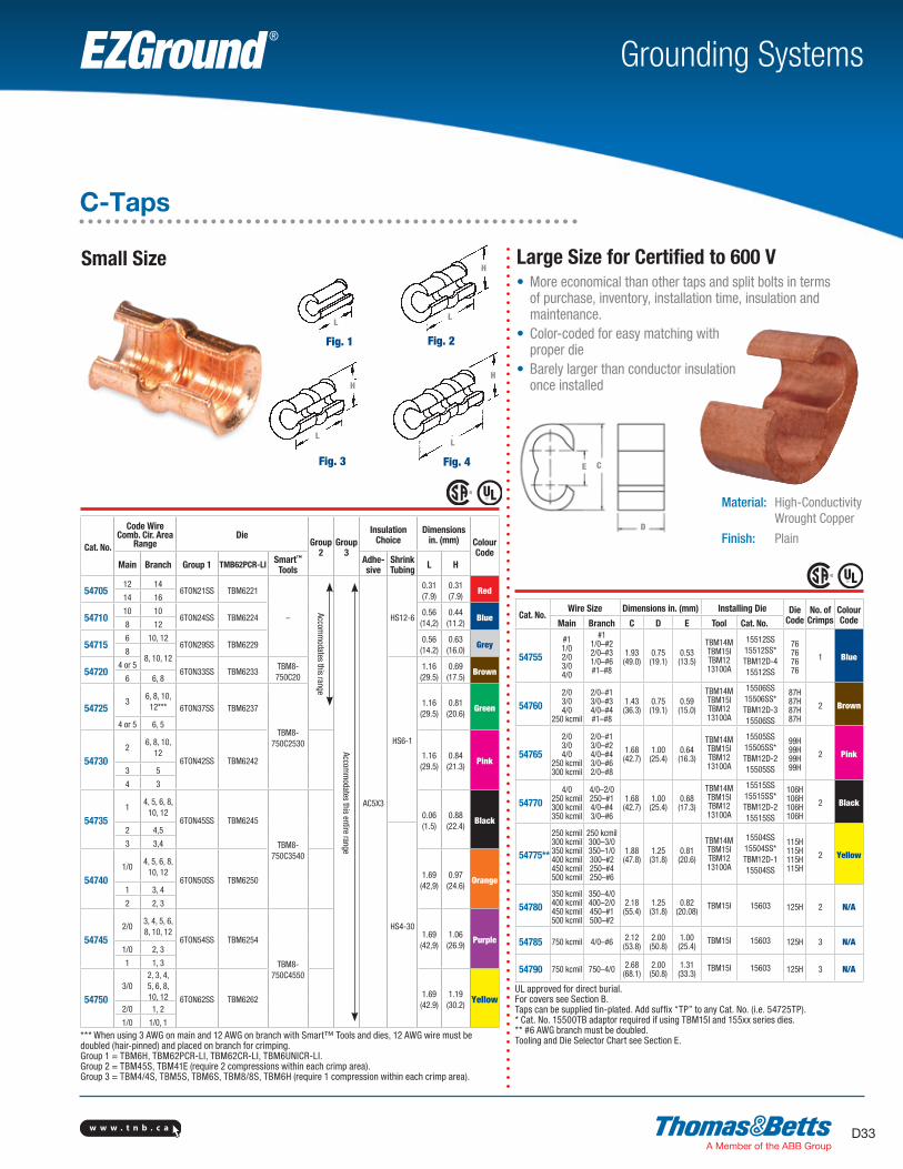
Cat. No.
Code Wire Comb. Cir. Area
Range Die
Group 2
Group 3
Insulation Choice
Dimensions in. (mm) Colour
CodeMain Branch Group 1 TMB62PCR-LI Smart™
ToolsAdhe-sive
Shrink Tubing L H
5470512 14
6TON21SS TBM6221
–
Accomm
odates this range
Accomm
odates this entire range
AC5X3
HS12-6
0.31 (7.9)
0.31 (7.9)
Red14 16
5471010 10
6TON24SS TBM62240.56 (14,2)
0.44 (11.2)
Blue8 12
547156 10, 12
6TON29SS TBM62290.56 (14.2)
0.63 (16.0)
Grey8
8, 10, 12
547204 or 5
6TON33SS TBM6233TBM8-750C20
HS6-1
1.16 (29.5)
0.69 (17.5)
Brown6 6, 8
547253
6, 8, 10, 12*** 6TON37SS TBM6237
TBM8-750C2530
1.16 (29.5)
0.81 (20.6)
Green
4 or 5 6, 5
547302
6, 8, 10, 12
6TON42SS TBM62421.16 (29.5)
0.84 (21.3)
Pink3 5
4 3
547351
4, 5, 6, 8, 10, 12
6TON45SS TBM6245
TBM8-750C3540
0.06 (1.5)
0.88 (22.4)
Black2 4,5
HS4-30
3 3,4
547401/0
4, 5, 6, 8, 10, 12
6TON50SS TBM62501.69 (42,9)
0.97 (24.6)
Orange1 3, 4
2 2, 3
547452/0
3, 4, 5, 6, 8, 10, 12
6TON54SS TBM6254
TBM8-750C4550
1.69 (42,9)
1.06 (26.9)
Purple1/0 2, 3
1 1, 3
547503/0
2, 3, 4, 5, 6, 8, 10, 12 6TON62SS TBM6262
1.69 (42.9)
1.19 (30.2)
Yellow2/0 1, 2
1/0 1/0, 1
*** When using 3 AWG on main and 12 AWG on branch with Smart™ Tools and dies, 12 AWG wire must be doubled (hair-pinned) and placed on branch for crimping.Group 1 = TBM6H, TBM62PCR-LI, TBM62CR-LI, TBM6UNICR-LI.Group 2 = TBM45S, TBM41E (require 2 compressions within each crimp area).Group 3 = TBM4/4S, TBM5S, TBM6S, TBM8/8S, TBM6H (require 1 compression within each crimp area).
Fig. 3
HH
LL
Cat. No.Wire Size Dimensions in. (mm) Installing Die Die
CodeNo. of
CrimpsColour CodeMain Branch C D E Tool Cat. No.
54755
#11/02/03/04/0
#11/0–#22/0–#31/0–#6#1–#8
1.93 (49.0)
0.75 (19.1)
0.53 (13.5)
TBM14MTBM15ITBM1213100A
15512SS15512SS*TBM12D-415512SS
76767676
1 Blue
547602/03/04/0
250 kcmil
2/0–#13/0–#34/0–#4#1–#8
1.43 (36.3)
0.75 (19.1)
0.59 (15.0)
TBM14MTBM15ITBM1213100A
15506SS15506SS*TBM12D-315506SS
87H87H87H87H
2 Brown
54765
2/03/04/0
250 kcmil300 kcmil
2/0–#13/0–#24/0–#43/0–#62/0–#8
1.68 (42.7)
1.00 (25.4)
0.64 (16.3)
TBM14MTBM15ITBM1213100A
15505SS15505SS*TBM12D-215505SS
99H99H99H99H
2 Pink
547704/0
250 kcmil300 kcmil350 kcmil
4/0–2/0250–#14/0–#43/0–#6
1.68 (42.7)
1.00 (25.4)
0.68 (17.3)
TBM14MTBM15ITBM1213100A
15515SS15515SS*TBM12D-215515SS
106H106H106H106H
2 Black
54775**
250 kcmil300 kcmil350 kcmil400 kcmil450 kcmil500 kcmil
250 kcmil300–3/0350–1/0300–#2250–#4250–#6
1.88 (47.8)
1.25 (31.8)
0.81 (20.6)
TBM14MTBM15ITBM1213100A
15504SS15504SS*TBM12D-115504SS
115H115H115H115H
2 Yellow
54780350 kcmil400 kcmil450 kcmil500 kcmil
350–4/0400–2/0450–#1500–#2
2.18 (55.4)
1.25 (31.8)
0.82 (20.08)
TBM15I 15603 125H 2 N/A
54785 750 kcmil 4/0–#6 2.12 (53.8)
2.00 (50.8)
1.00 (25.4)
TBM15I 15603 125H 3 N/A
54790 750 kcmil 750–4/0 2.68 (68.1)
2.00 (50.8)
1.31 (33.3)
TBM15I 15603 125H 3 N/A
UL approved for direct burial.For covers see Section B.Taps can be supplied tin-plated. Add suffix “TP” to any Cat. No. (i.e. 54725TP).* Cat. No. 15500TB adaptor required if using TBM15I and 155xx series dies.** #6 AWG branch must be doubled.Tooling and Die Selector Chart see Section E.
C-Taps
Small Size
Fig. 1 Fig. 2
H
LL
Large Size for Certified to 600 V• More economical than other taps and split bolts in terms
of purchase, inventory, installation time, insulation and maintenance.
• Color-coded for easy matching with proper die
• Barely larger than conductor insulation once installed
CE
D
Material: High-Conductivity Wrought Copper
Finish: Plain
Fig. 4

w w w . t n b . c aD34
Grounding SystemsEZGround ®
Pigtail Connectors
Hex Compression intimately bonds directly to copper clad ground rod• Figure-8 connectors• Conforms to IEEE 837 standard• UL Listed
When connecting cable to copper clad ground rod for direct burial or in concrete, the connector shall be wrought copper with minimum conductivity of 99% I.A.C.S., such as Thomas & Betts series GR12-306. Hex compression with die code embossing shall be used.
Cat. No. Cable Range Copper Clad Ground Rod (in.)
Die Code for TBM14M, TBM15, 13100A or TBM15I Die Cat. No.
GR12-306 One Cable: 3/0 to 6 AWG Two Cables: 2 to 6 AWG 1/2
87H 15506GR58-406 One Cable: 4/0 to 6 AWG
Two Cables: 2 to 6 AWG 5/8
GR34-4010 One Cable:4/0 to 1/0 AWG 3/4 99H 15505
2
2
* Number of crimps.
Cat. No. Fig. Cable Range H in. (mm)
Die Code for 14- and 15-Ton Tools
GP2250-2 12–250 kcmil
3.63 (92.2) 15G86R
GP2250-4 2 4.22 (107.2) 15G86R
GP250500-2 1250–500 kcmil
3.63 (92.2) 15G126R
GP250500-4 2 4.22 (107.2) 15G126R
Ground Plates
1
1
2
2
* Number of crimps.
DB
DB
Hc -16 UNC
Cable Range
2X d -13 UNC1f
2
5A
Cable RangeH
3b 1f
c -16 UNC
4X d -13 UNC1 3/4
Fig. 1 Fig. 2
13⁄4
31⁄4
13⁄4
3⁄42
525⁄32
2X 1⁄2-13 UNC
4X 1⁄2-13 UNC
3⁄8-16 UNC
Cable Range Cable Range
3⁄8-16 UNC
H
1-3/4
H
23/43-1/4
2X 1/2–13 UNC
4X 1/2–13 UNC
3/8–16 UNC3/8–16 UNC
5-25/32 1-3/4
Cable RangeCable Range
Figure 1 Figure 2
SectionD-grounding-systems.indd 34 6/6/2017 9:43:36 AM
w w w . t n b . c a D35
Grounding SystemsEZGround ®
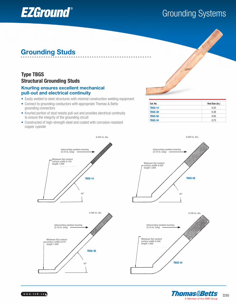
Grounding Studs
Type TBGS Structural Grounding StudsKnurling ensures excellent mechanical pull-out and electrical continuity• Easily welded to steel structures with minimal construction welding equipment• Connect to grounding conductors with appropriate Thomas & Betts grounding connectors• Knurled portion of stud resists pull-out and provides electrical continuity to ensure the integrity of the grounding circuit• Constructed of high-strength steel and coated with corrosion-resistant copper cyanide
Cat. No. Rod Size (in.)
TBGS-14 0.25
TBGS-38 0.38
TBGS-58 0.63
TBGS-34 0.75
45° 45°
45°
TBGS-14
TBGS-38
TBGS-58
TBGS-34
0.235" Dia
0.360" Dia 0.705" Dia
0.580" Dia
Minimum �at contactsurface WIDTH 0.135
LENGTH 1.000
Minimum �at contactsurface WIDTH 0.215
LENGTH 1.000
Minimum �at contactsurface WIDTH 0.420
LENGTH 1.000
Minimum �at contactsurface WIDTH 0.450
LENGTH 1.000
Intersecting medium knuring(2.10" long)
Intersecting medium knuring(2.10" long)
Intersecting medium knuring(2.10" long)
Intersecting medium knuring(2.10" long)
0.235 in. dia.
Minimum flat contactsurface width 0.135length 1.000
Intersecting medium knuring(2.10 in. long)
0.580 in. dia.
Minimum flat contactsurface width 0.420length 1.000
Intersecting medium knuring(2.10 in. long)
TBGS-14 TBGS-58
45° 45°
0.360 in. dia. 0.705 in. dia.
Intersecting medium knuring(2.10 in. long)
Intersecting medium knuring(2.10 in. long)
Minimum flat contactsurface width 0.215length 1.000
Minimum flat contactsurface width 0.450length 1.000
TBGS-34
TBGS-38
45°
SectionD-grounding-systems.indd 35 6/6/2017 9:43:36 AM
w w w . t n b . c aD36
Grounding SystemsEZGround ®
1⁄4 Bus GBBC22
Use this side of the connector when using only one wire. Use this side of the connector only when using two wires.
Use withONE WIRE
#2 AWG
Use with 2nd WIRE#2 AWG
1.03
"
1.40"
1⁄4 Bus GBBC26
Use withONE WIRE
#2-#6 AWG
Use with2nd WIRE#6 AWG
1.03
"
1.40"
Bus Bar Connectors
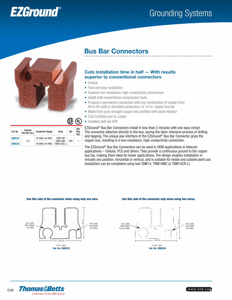
Cuts installation time in half — With results superior to conventional connectors• Unique• Fast and easy installation• Superior low-resistance, high-conductivity connections• Install with conventional compression tools• Produce a permanent connection with any combination of copper from #6 to #2 solid or stranded conductors, to 1/4 in. copper bus bar• Made from pure wrought copper and prefilled with oxide inhibitor• CSA Certified and UL Listed• Installed with die HDF
EZGround® Bus Bar Connectors install in less than 2 minutes with one easy crimp! The connector attaches directly to the bus, saving the labor-intensive process of drilling and tapping. The unique jaw interface of the EZGround® Bus Bar Connector grips the copper bus, resulting in a low-resistance, high-conductivity connection.
The EZGround® Bus Bar Connectors can be used in OEM applications or telecom applications – Cellular, PCS and others. They provide a continuous ground to the copper bus bar, making them ideal for tower applications. The design enables installation in virtually any position, horizontal or vertical, and is suitable for inside and outside plant use. Installation can be completed using tool TBM14, TBM14MC or TBM14CR-LI.
Cat. No. Ground Bus Bar (in.) Conductor Range Tools Die
Std. Pkg.Qty.
GBBC221/4
#2 AWG–#2 AWG TBM14MTBM14MC
TBM14CR-LIHDF 1
GBBC26 #6 AWG–#2 AWG
Use this side of the connector when using only one wire. Use this side of the connector only when using two wires.
Use with ONE WIRE
#2 AWG
1.40 in.
Use with 2nd WIRE #2 AWG
1/4 in. BusCat. No. GBBC22
1/4 in. BusCat. No. GBBC26
Use with ONE WIRE
#2-#6 AWG
1.40 in.
1.03
in.
1.03
in.
Use with 2nd WIRE #6 AWG
SectionD-grounding-systems.indd 36 6/6/2017 9:43:37 AM
w w w . t n b . c a D37
Grounding SystemsEZGround ®
Ground Rods
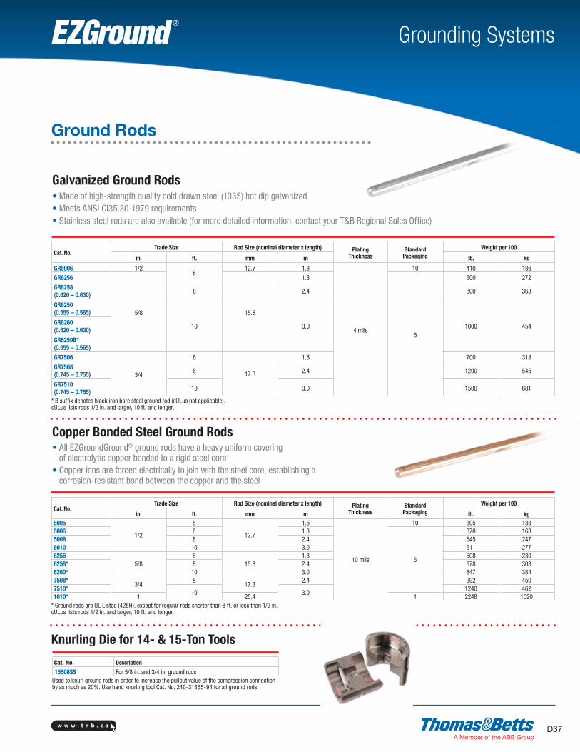
Galvanized Ground Rods• Made of high-strength quality cold drawn steel (1035) hot dip galvanized• Meets ANSI CI35.30-1979 requirements• Stainless steel rods are also available (for more detailed information, contact your T&B Regional Sales Office)
Copper Bonded Steel Ground Rods• All EZGroundGround® ground rods have a heavy uniform covering
of electrolytic copper bonded to a rigid steel core• Copper ions are forced electrically to join with the steel core, establishing a
corrosion-resistant bond between the copper and the steel
Cat. No.Trade Size Rod Size (nominal diameter x length) Plating
ThicknessStandard
PackagingWeight per 100
in. ft. mm m lb. kg
GR5006 1/26
12.7 1.8
4 mils
10 410 186GR6256
5/8 15.8
1.8
5
600 272
GR6258(0.620 – 0.630) 8 2.4 800 363
GR6250(0.555 – 0.565)
10 3.0 1000 454GR6260(0.620 – 0.630)
GR6250B*(0.555 – 0.565)GR7506
3/4
6
17.3
1.8 700 318
GR7508(0.745 – 0.755) 8 2.4 1200 545
GR7510(0.745 – 0.755) 10 3.0 1500 681
* B suffix denotes black iron bare steel ground rod (cULus not applicable).cULus lists rods 1/2 in. and larger, 10 ft. and longer.
Cat. No.Trade Size Rod Size (nominal diameter x length) Plating
ThicknessStandard
PackagingWeight per 100
in. ft. mm m lb. kg5005
1/2
5
12.7
1.5
10 mils
10 305 1385006 6 1.8
5
370 1685008 8 2.4 545 2475010 10 3.0 611 2776256
5/86
15.81.8 508 230
6258* 8 2.4 678 3086260* 10 3.0 847 3847508*
3/48
17.32.4 992 450
7510*10 3.0
1240 4621010* 1 25.4 1 2248 1020
* Ground rods are UL Listed (425H), except for regular rods shorter than 8 ft. or less than 1/2 in.cULus lists rods 1/2 in. and larger, 10 ft. and longer.
Cat. No. Description
15508SS For 5/8 in. and 3/4 in. ground rodsUsed to knurl ground rods in order to increase the pullout value of the compression connection by as much as 20%. Use hand knurling tool Cat. No. 240-31565-94 for all ground rods.
Knurling Die for 14- & 15-Ton Tools
w w w . t n b . c aD38
Grounding SystemsEZGround ®
Ground Rods
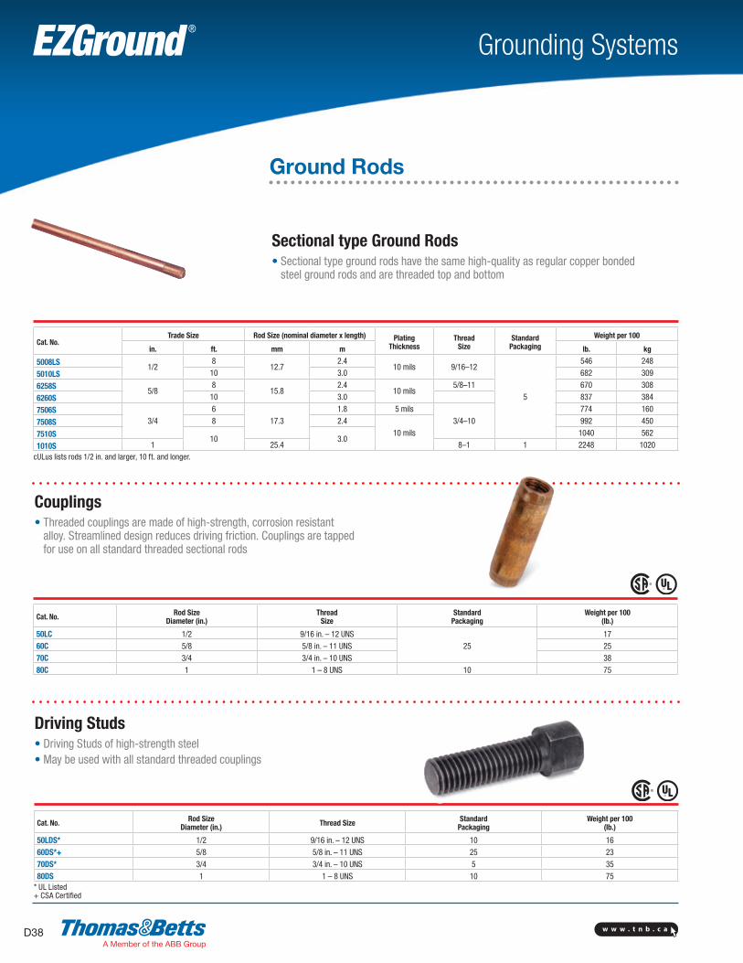
Couplings• Threaded couplings are made of high-strength, corrosion resistant
alloy. Streamlined design reduces driving friction. Couplings are tapped for use on all standard threaded sectional rods
Cat. No. Rod Size Diameter (in.)
Thread Size
StandardPackaging
Weight per 100(lb.)
50LC 1/2 9/16 in. – 12 UNS25
1760C 5/8 5/8 in. – 11 UNS 2570C 3/4 3/4 in. – 10 UNS 3880C 1 1 – 8 UNS 10 75
Driving Studs• Driving Studs of high-strength steel• May be used with all standard threaded couplings
Cat. No. Rod SizeDiameter (in.) Thread Size Standard
PackagingWeight per 100
(lb.)
50LDS* 1/2 9/16 in. – 12 UNS 10 1660DS*+ 5/8 5/8 in. – 11 UNS 25 2370DS* 3/4 3/4 in. – 10 UNS 5 3580DS 1 1 – 8 UNS 10 75
* UL Listed+ CSA Certified
Cat. No.Trade Size Rod Size (nominal diameter x length) Plating
ThicknessThread
SizeStandard
PackagingWeight per 100
in. ft. mm m lb. kg
5008LS1/2
812.7
2.410 mils 9/16–12
5
546 248
5010LS 10 3.0 682 309
6258S5/8
815.8
2.410 mils
5/8–11 670 308
6260S 10 3.0 837 384
7506S3/4
617.3
1.8 5 mils3/4–10
774 160
7508S 8 2.410 mils
992 450
7510S10 3.0
1040 562
1010S 1 25.4 8–1 1 2248 1020cULus lists rods 1/2 in. and larger, 10 ft. and longer.
Sectional type Ground Rods• Sectional type ground rods have the same high-quality as regular copper bonded
steel ground rods and are threaded top and bottom
w w w . t n b . c a D39
Grounding SystemsEZGround ®
Ground Rods
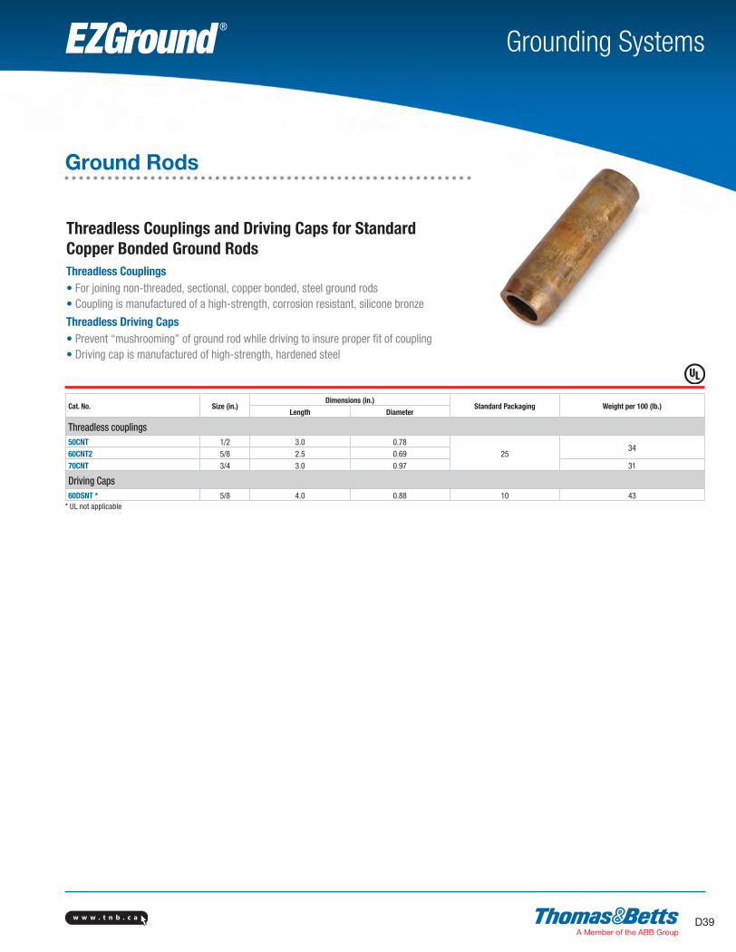
Threadless Couplings and Driving Caps for Standard Copper Bonded Ground RodsThreadless Couplings• For joining non-threaded, sectional, copper bonded, steel ground rods• Coupling is manufactured of a high-strength, corrosion resistant, silicone bronze
Threadless Driving Caps• Prevent “mushrooming” of ground rod while driving to insure proper fit of coupling• Driving cap is manufactured of high-strength, hardened steel
Cat. No. Size (in.)Dimensions (in.)
Standard Packaging Weight per 100 (lb.)Length Diameter
Threadless couplings50CNT 1/2 3.0 0.78
2534
60CNT2 5/8 2.5 0.6970CNT 3/4 3.0 0.97 31
Driving Caps60DSNT * 5/8 4.0 0.88 10 43
* UL not applicable
SectionD-grounding-systems.indd 39 6/6/2017 9:43:40 AM
w w w . t n b . c aD40
Grounding SystemsEZGround ®
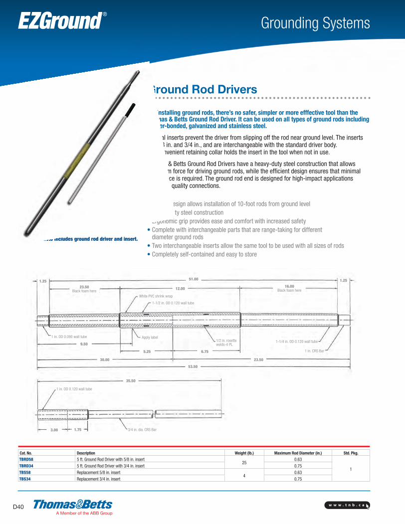
Ground Rod Drivers
For installing ground rods, there’s no safer, simpler or more efffective tool than the Thomas & Betts Ground Rod Driver. It can be used on all types of ground rods including copper-bonded, galvanized and stainless steel.
Integral inserts prevent the driver from slipping off the rod near ground level. The inserts are 5/8 in. and 3/4 in., and are interchangeable with the standard driver body. The convenient retaining collar holds the insert in the tool when not in use.
Thomas & Betts Ground Rod Drivers have a heavy-duty steel construction that allows maximum force for driving ground rods, while the efficient design ensures that minimal lifting force is required. The ground rod end is designed for high-impact applications to ensure quality connections.
• Unique design allows installation of 10-foot rods from ground level• Heavy-duty steel construction• Ergonomic grip provides ease and comfort with increased safety• Complete with interchangeable parts that are range-taking for different
diameter ground rods• Two interchangeable inserts allow the same tool to be used with all sizes of rods• Completely self-contained and easy to store
Photo includes ground rod driver and insert.
Cat. No. Description Weight (lb.) Maximum Rod Diameter (in.) Std. Pkg.TBRD58 5 ft. Ground Rod Driver with 5/8 in. insert
250.63
1TBRD34 5 ft. Ground Rod Driver with 3/4 in. insert 0.75TBS58 Replacement 5/8 in. insert
40.63
TBS34 Replacement 3/4 in. insert 0.75
51.001.25 1.25
12.0023.50Black foam here
16.00Black foam here
White PVC shrink wrap
1-1/2 in. OD 0.120 wall tube
1 in. OD 0.090 wall tube Apply label1/2 in. rosettewelds-4 PL
1-1/4 in. OD 0.120 wall tube
1 in. CRS Bar
9.50
30.00
5.25 6.75
23.50
53.50
35.50
3.00 1.75
1 in. OD 0.120 wall tube
3/4 in. dia. CRS Bar
SectionD-grounding-systems.indd 40 6/6/2017 9:43:44 AM
w w w . t n b . c a D41
Grounding Systems
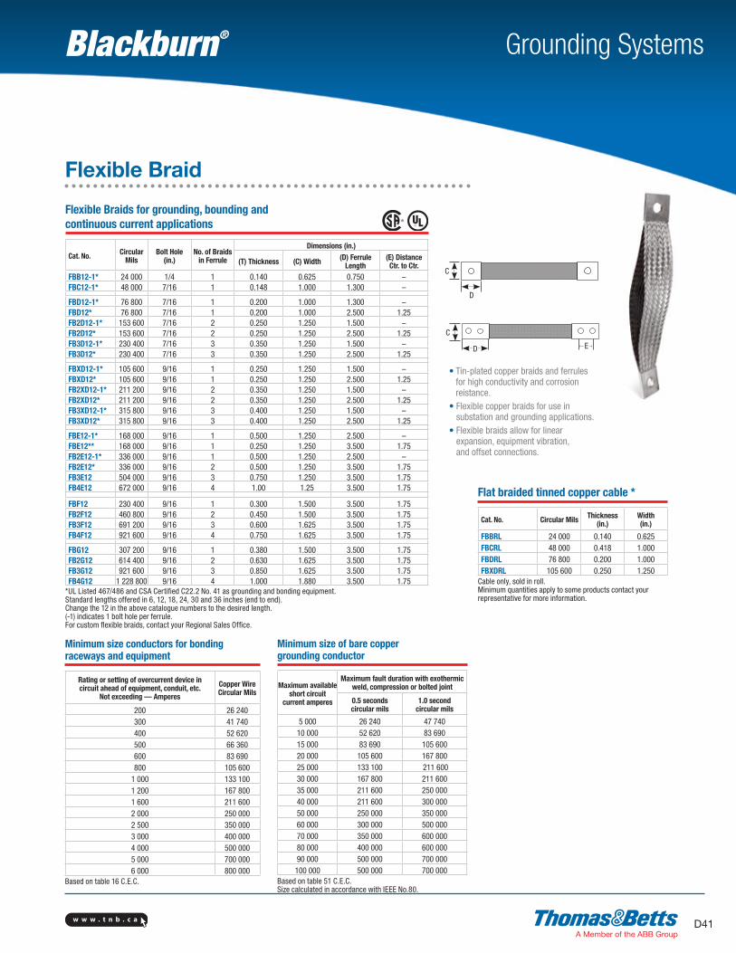
Flexible Braid
Flexible Braids for grounding, bounding and continuous current applications
Cat. No. Circular Mils
Bolt Hole (in.)
No. of Braidsin Ferrule
Dimensions (in.)
(T) Thickness (C) Width (D) Ferrule Length
(E) Distance Ctr. to Ctr.
FBB12-1* 24 000 1/4 1 0.140 0.625 0.750 –FBC12-1* 48 000 7/16 1 0.148 1.000 1.300 –
FBD12-1* 76 800 7/16 1 0.200 1.000 1.300 –FBD12* 76 800 7/16 1 0.200 1.000 2.500 1.25FB2D12-1* 153 600 7/16 2 0.250 1.250 1.500 –FB2D12* 153 600 7/16 2 0.250 1.250 2.500 1.25FB3D12-1* 230 400 7/16 3 0.350 1.250 1.500 –FB3D12* 230 400 7/16 3 0.350 1.250 2.500 1.25
FBXD12-1* 105 600 9/16 1 0.250 1.250 1.500 –FBXD12* 105 600 9/16 1 0.250 1.250 2.500 1.25FB2XD12-1* 211 200 9/16 2 0.350 1.250 1.500 –FB2XD12* 211 200 9/16 2 0.350 1.250 2.500 1.25FB3XD12-1* 315 800 9/16 3 0.400 1.250 1.500 –FB3XD12* 315 800 9/16 3 0.400 1.250 2.500 1.25
FBE12-1* 168 000 9/16 1 0.500 1.250 2.500 –FBE12** 168 000 9/16 1 0.250 1.250 3.500 1.75FB2E12-1* 336 000 9/16 1 0.500 1.250 2.500 –FB2E12* 336 000 9/16 2 0.500 1.250 3.500 1.75FB3E12 504 000 9/16 3 0.750 1.250 3.500 1.75FB4E12 672 000 9/16 4 1.00 1.25 3.500 1.75
FBF12 230 400 9/16 1 0.300 1.500 3.500 1.75FB2F12 460 800 9/16 2 0.450 1.500 3.500 1.75FB3F12 691 200 9/16 3 0.600 1.625 3.500 1.75FB4F12 921 600 9/16 4 0.750 1.625 3.500 1.75
FBG12 307 200 9/16 1 0.380 1.500 3.500 1.75FB2G12 614 400 9/16 2 0.630 1.625 3.500 1.75FB3G12 921 600 9/16 3 0.850 1.625 3.500 1.75FB4G12 1 228 800 9/16 4 1.000 1.880 3.500 1.75
*UL Listed 467/486 and CSA Certified C22.2 No. 41 as grounding and bonding equipment.Standard lengths offered in 6, 12, 18, 24, 30 and 36 inches (end to end).Change the 12 in the above catalogue numbers to the desired length.(-1) indicates 1 bolt hole per ferrule.For custom flexible braids, contact your Regional Sales Office.
Flat braided tinned copper cable *
Cat. No. Circular Mils Thickness (in.)
Width(in.)
FBBRL 24 000 0.140 0.625FBCRL 48 000 0.418 1.000FBDRL 76 800 0.200 1.000FBXDRL 105 600 0.250 1.250
Cable only, sold in roll. Minimum quantities apply to some products contact your representative for more information.
C
D
Minimum size conductors for bonding raceways and equipment
Rating or setting of overcurrent device in circuit ahead of equipment, conduit, etc.
Not exceeding — Amperes
Copper Wire Circular Mils
200 26 240300 41 740400 52 620500 66 360600 83 690800 105 600
1 000 133 1001 200 167 8001 600 211 6002 000 250 0002 500 350 0003 000 400 0004 000 500 0005 000 700 0006 000 800 000
Based on table 16 C.E.C.
Minimum size of bare copper grounding conductor
Maximum available short circuit
current amperes
Maximum fault duration with exothermic weld, compression or bolted joint
0.5 secondscircular mils
1.0 secondcircular mils
5 000 26 240 47 74010 000 52 620 83 69015 000 83 690 105 60020 000 105 600 167 800 25 000 133 100 211 60030 000 167 800 211 60035 000 211 600 250 00040 000 211 600 300 00050 000 250 000 350 00060 000 300 000 500 00070 000 350 000 600 000 80 000 400 000 600 00090 000 500 000 700 000100 000 500 000 700 000
Based on table 51 C.E.C.Size calculated in accordance with IEEE No.80.
• Tin-plated copper braids and ferrules for high conductivity and corrosion reistance.
• Flexible copper braids for use in substation and grounding applications.
• Flexible braids allow for linear expansion, equipment vibration, and offset connections.
C
D E
w w w . t n b . c aD42
Grounding Systems
GRX005
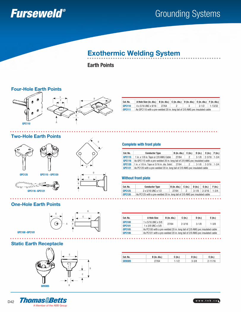
Exothermic Welding System
Earth Points
One-Hole Earth Points
Static Earth Receptacle
GPC110
GPC100 -GPC101
ED
B
C
D
D
C
E
E
A
C
F
A
B
B
Two-Hole Earth Points
GPC125 GPC115 - GPC120
F
E
GPC116 -GPC121
B
C
D
Cat. No. A Hole Size (in. dia.) B (in. dia.) C (in. dia.) D (in. dia.) E (in. dia.) F (in. dia.)
GPC110 4 x 5/16 UNC x 9/16 27/64 2 3 2-1/2 1-13/32GPC111 As GPC110 with a pre-welded 20 in. long tail of 2/0 AWG pvc insulated cable
Four-Hole Earth Points
Complete with front plate
Cat. No. Conductor Type B (in. dia.) C (in.) D (in.) E (in.) F (in.)
GPC115 1 in. x 1/8 in. Tape or 2/0 AWG Cable 27/64 2 3-1/8 2-3/16 1-3/4GPC116 As GPC115 with a pre-welded 20 in. long tail of 2/0 AWG pvc insulated cableGPC120 1 in. x 1/8 in. Tape or 5/16 in. dia. Solid 27/64 2 3-1/8 2-3/16 1-3/4
GPC121 As PC120 with a pre-welded 20 in. long tail of 2/0 AWG pvc insulated cable
Without front plate
Cat. No. Conductor Type B (in. dia.) C (in.) D (in.) E (in.) F (in.)
GPC125 2 x 5/16 UNC x 1/2 27/64 2 3-1/8 2-3/16 1-3/4GPC126 As PC125 with a pre-welded 20 in. long tail of 2/0 AWG pvc insulated cable
Cat. No. A Hole Size B (in. dia.) C (in.) D (in.) E (in.)
GPC100 1 x 5/16 UNC x 5/827/64 2-3/16 3-1/8 1-3/8
GPC101 1 x 3/8 UNC x 5/8GPC105 As PC100 with a pre-welded 20 in. long tail of 2/0 AWG pvc insulated cableGPC106 As PC101 with a pre-welded 20 in. long tail of 2/0 AWG pvc insulated cable
Cat. No. B (in. dia.) C (in.) D (in.) E (in.)
GRX005 27/64 1-1/2 3-3/8 2-11/16
SectionD-grounding-systems.indd 42 6/6/2017 9:43:49 AM
w w w . t n b . c a D43
Grounding Systems
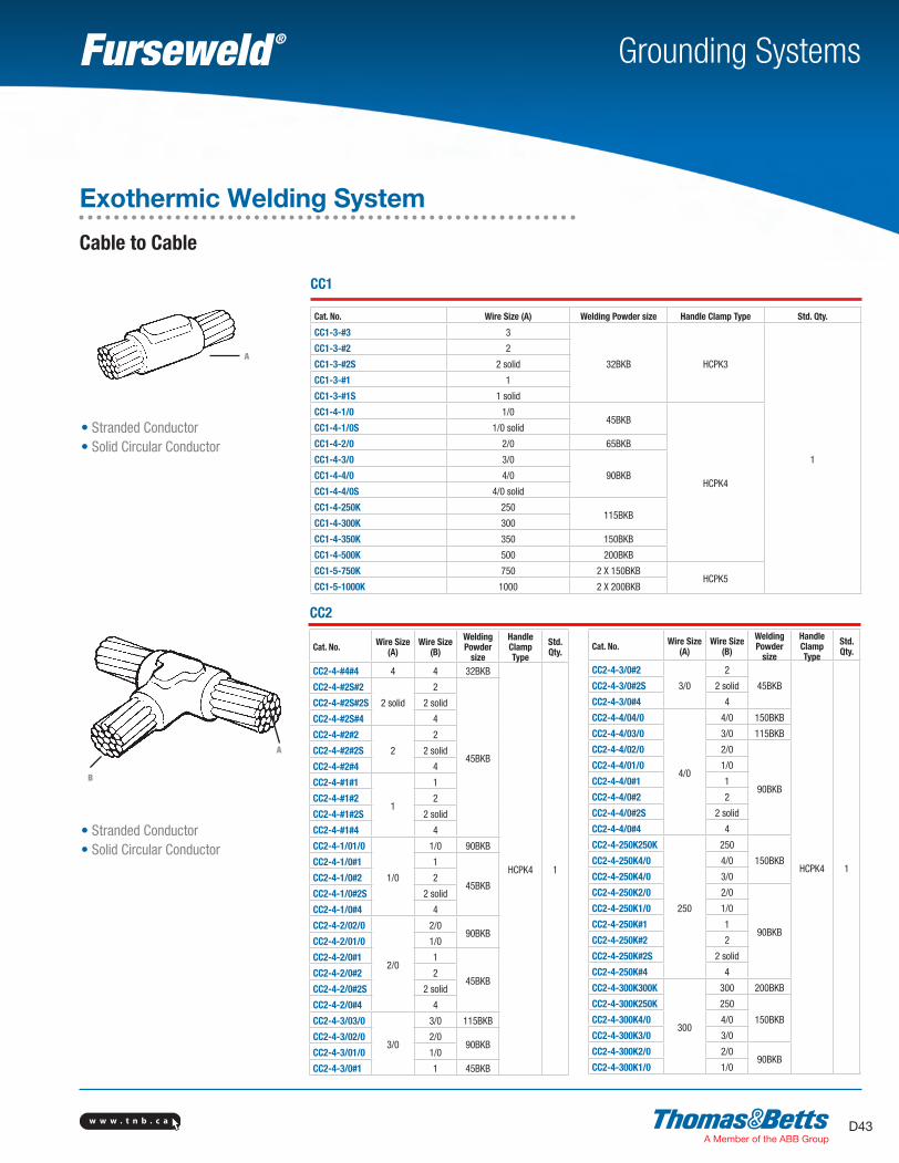
Exothermic Welding System
Cable to Cable
• Stranded Conductor• Solid Circular Conductor
CC1
Cat. No. Wire Size (A) Welding Powder size Handle Clamp Type Std. Qty.
CC1-3-#3 3
32BKB HCPK3
1
CC1-3-#2 2
CC1-3-#2S 2 solid
CC1-3-#1 1
CC1-3-#1S 1 solid
CC1-4-1/0 1/045BKB
HCPK4
CC1-4-1/0S 1/0 solid
CC1-4-2/0 2/0 65BKB
CC1-4-3/0 3/0
90BKBCC1-4-4/0 4/0
CC1-4-4/0S 4/0 solid
CC1-4-250K 250115BKB
CC1-4-300K 300
CC1-4-350K 350 150BKB
CC1-4-500K 500 200BKB
CC1-5-750K 750 2 X 150BKBHCPK5
CC1-5-1000K 1000 2 X 200BKB
A
• Stranded Conductor• Solid Circular Conductor
B
Cat. No. Wire Size (A)
Wire Size (B)
Welding Powder
size
Handle Clamp Type
Std. Qty.
CC2-4-#4#4 4 4 32BKB
HCPK4 1
CC2-4-#2S#2
2 solid
2
45BKB
CC2-4-#2S#2S 2 solid
CC2-4-#2S#4 4
CC2-4-#2#2
2
2
CC2-4-#2#2S 2 solid
CC2-4-#2#4 4
CC2-4-#1#1
1
1
CC2-4-#1#2 2
CC2-4-#1#2S 2 solid
CC2-4-#1#4 4
CC2-4-1/01/0
1/0
1/0 90BKB
CC2-4-1/0#1 1
45BKBCC2-4-1/0#2 2
CC2-4-1/0#2S 2 solid
CC2-4-1/0#4 4
CC2-4-2/02/0
2/0
2/090BKB
CC2-4-2/01/0 1/0
CC2-4-2/0#1 1
45BKBCC2-4-2/0#2 2
CC2-4-2/0#2S 2 solid
CC2-4-2/0#4 4
CC2-4-3/03/0
3/0
3/0 115BKB
CC2-4-3/02/0 2/090BKB
CC2-4-3/01/0 1/0
CC2-4-3/0#1 1 45BKB
CC2
Cat. No. Wire Size (A)
Wire Size (B)
Welding Powder
size
Handle Clamp Type
Std. Qty.
CC2-4-3/0#2
3/0
2
45BKB
HCPK4 1
CC2-4-3/0#2S 2 solid
CC2-4-3/0#4 4
CC2-4-4/04/0
4/0
4/0 150BKB
CC2-4-4/03/0 3/0 115BKB
CC2-4-4/02/0 2/0
90BKB
CC2-4-4/01/0 1/0
CC2-4-4/0#1 1
CC2-4-4/0#2 2
CC2-4-4/0#2S 2 solid
CC2-4-4/0#4 4
CC2-4-250K250K
250
250
150BKBCC2-4-250K4/0 4/0
CC2-4-250K4/0 3/0
CC2-4-250K2/0 2/0
90BKB
CC2-4-250K1/0 1/0
CC2-4-250K#1 1
CC2-4-250K#2 2
CC2-4-250K#2S 2 solid
CC2-4-250K#4 4
CC2-4-300K300K
300
300 200BKB
CC2-4-300K250K 250
150BKBCC2-4-300K4/0 4/0
CC2-4-300K3/0 3/0
CC2-4-300K2/0 2/090BKB
CC2-4-300K1/0 1/0
A
SectionD-grounding-systems.indd 43 6/6/2017 9:43:50 AM
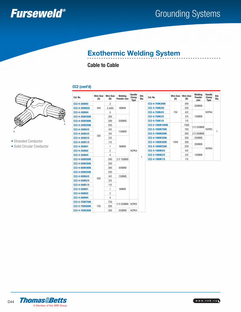
w w w . t n b . c aD44
Grounding Systems
• Stranded Conductor• Solid Circular Conductor
CC2 (cont’d)
Cat. No. Wire Size (A)
Wire Size (B)
Welding Powder size
Handle Clamp Type
Std. Qty.
CC2-4-300K#2
300
2
90BKB
HCPK4
1
CC2-4-300K#2S 2 solid
CC2-4-300K#4 4
CC2-4-350K350K
350
350
200BKBCC2-4-350K300K 300
CC2-4-350K250K 250
CC2-4-350K4/0 4/0150BKB
CC2-4-350K3/0 3/0
CC2-4-350K2/0 2/0
90BKB
CC2-4-350K1/0 1/0
CC2-4-350K#1 1
CC2-4-350K#2 2
CC2-4-350K#4 4
CC2-4-500K500K
500
500 2 X 150BKB
CC2-4-500K350K 350
200BKBCC2-4-500K300K 300
CC2-4-500K250K 250
CC2-4-500K4/0 4/0 150BKB
CC2-4-500K2/0 2/0
90BKB
CC2-4-500K1/0 1/0
CC2-4-500K#1 1
CC2-4-500K#2 2
CC2-4-500K#4 4
CC2-5-750K750K
750
7502 X 250BKB HCPK5
CC2-5-750K500K 500
CC2-4-750K350K 350 250BKB HCPK4
Cat. No. Wire Size (A)
Wire Size (B)
Welding Powder
size
Handle Clamp Type
Std. Qty.
CC2-4-750K300K
750
300200BKB
HCPK4
1
CC2-4-750K250 250
CC2-4-750K4/0 4/0
150BKBCC2-4-750K2/0 2/0
CC2-4-750K1/0 1/0
CC2-5-1000K1000K
1000
10002 X 250BKB
HCPK5CC2-5-1000K750K 750
CC2-5-1000K500K 500 2 X 200BKB
CC2-4-1000K350K 350 250BKB
HCPK4
CC2-4-1000K300K 300200BKB
CC2-4-1000K250K 250
CC2-4-1000K4/0 4/0
150BKBCC2-4-1000K2/0 2/0
CC2-4-1000K1/0 1/0
Exothermic Welding System
Cable to Cable
A
B
SectionD-grounding-systems.indd 44 6/6/2017 9:43:50 AM
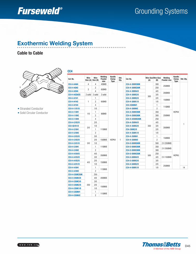
w w w . t n b . c a D45
Grounding Systems
• Stranded Conductor• Solid Circular Conductor
B
CC4
Cat. No. Wire Size (A)
Wire Size (B)
Welding Powder
size
Handle Clamp Type
Std. Qty.
CC4-4-#4#4 4 4 45BKB
HCPK4 1
CC4-4-#2#22
265BKB
CC4-4-#2#4 4
CC4-4-#2S#2S 2 solid 2 solid 2 solid
CC4-4-#1#1
1
1
65BKBCC4-4-#1#2 2
CC4-4-#1#4 4
CC4-4-1/01/0
1/0
1/0
90BKBCC4-4-1/0#1 1
CC4-4-1/0#2 2
CC4-4-1/0#4 4
CC4-4-2/02/0
2/0
2/0
115BKB
CC4-42/01/0 1/0
CC4-4-2/0#1 1
CC4-4-2/0#2 2
CC4-4-3/03/0
3/0
3/0
CC4-4-3/02/0 2/0 150BKB
CC4-4-3/01/0 1/0
115BKBCC4-4-3/0#1 1
CC4-4-3/0#2 2
CC4-4-4/04/0
4/0
4/0200BKB
CC4-4-4/03/0 3/0
CC4-4-4/02/0 2/0150BKB
CC4-4-4/01/0 1/0
CC4-4-4/0#1 1115BKB
CC4-4-4/0#2 2
CC4-4-250K250K
250
250
200BKBCC4-4-250K4/0 4/0
CC4-4-250K3/0 3/0
CC4-4-250K2/0 2/0150BKB
CC4-4-250K1/0 1/0
CC4-4-250K#1 1115BKB
CC4-4-250K#2 2
Cat. No. Wire Size (A)
Wire Size (B)
Welding Powder size
Handle Clamp Type
Std. Qty.
CC4-4-300K300K
300
300250BKB
HCPK4
1
CC4-4-300K250K 250
CC4-4-300K4/0 4/0200BKB
CC4-4-300K3/0 3/0
CC4-4-300K2/0 2/0150BKB
CC4-4-300K1/0 1/0
CC4-4300K#1 1115BKB
CC4-4-300K#2 2
CC4-4-350K350K
350
350
250BKBCC4-4-350K300K 300
CC4-4-4350K250K 250
CC4-4-350K4/0 4/0
200BKBCC4-4-350K3/0 3/0
CC4-350K2/0 2/0
CC4-4-350K1/0 1/0
CC4-4-350K#1 1150BKB
CC4-4-350K#2 2
CC4-5-500K500K
500
500 2 X 250BKB
HCPK5
CC4-5-500K350K 3502 X 200BKB
CC4-5-500K300K 300
CC4-5-500K250K 250
2 X 150BKBCC4-5-500K4/0 4/0
CC4-5-500K3/0 3/0
CC4-4-500K2/0 2/0250BKB
CC4-4-500K1/0 1/0 14
Exothermic Welding System
Cable to Cable
A
SectionD-grounding-systems.indd 45 6/6/2017 9:43:51 AM
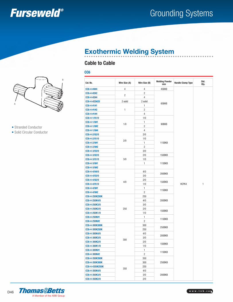
w w w . t n b . c aD46
Grounding Systems
B
• Stranded Conductor• Solid Circular Conductor
A
CC6
Cat. No. Wire Size (A) Wire Size (B) Welding Powder size Handle Clamp Type Std.
Qty.
CC6-4-#4#4 4 4 45BKB
HCPK4 1
CC6-4-#2#22
2
65BKB
CC6-4-#2#4 4
CC6-4-#2S#2S 2 solid 2 solid
CC6-4-#1#1
1
1
CC6-4-#1#2 2
CC6-4-#1#4 4
CC6-4-1/01/0
1/0
1/0
90BKBCC6-4-1/0#1 1
CC6-4-1/0#2 2
CC6-4-1/0#4 4
CC6-4-2/02/0
2/0
2/0
115BKB
CC6-4-2/01/0 1/0
CC6-4-2/0#1 1
CC6-4-2/0#2 2
CC6-4-3/03/0
3/0
3/0
CC6-4-3/02/0 2/0 150BKB
CC6-4-3/01/0 1/0
115BKBCC6-4-3/0#1 1
CC6-4-3/0#2
CC6-4-4/04/0
4/0
4/0200BKB
CC6-4-4/03/0 3/0
CC6-4-4/02/0 2/0150BKB
CC6-4-4/01/0 1/0
CC6-4-4/0#1 1115BKB
CC6-4-4/0#2 2
CC6-4-250K250K
250
250
200BKBCC6-4-250K4/0 4/0
CC6-4-250K3/0 3/0
CC6-4-250K2/0 2/0150BKB
CC6-4-250K1/0 1/0
CC6-4-250K#1 1115BKB
CC6-4-250K#2 2
CC6-4-300K300K
300
300250BKB
CC6-4-300K250K 250
CC6-4-300K4/0 4/0200BKB
CC6-4-300K3/0 3/0
CC6-4-300K2/0 2/0150BKB
CC6-4-300K1/0 1/0
CC6-4-300K#1 1115BKB
CC6-4-300K#2 2
CC6-4-350K350K
350
350
250BKBCC6-4-350K300K 300
CC6-4-4350K250K 250
CC6-4-350K4/0 4/0
200BKBCC6-4-350K3/0 3/0
CC6-4-350K2/0 2/0
Exothermic Welding System
Cable to Cable
SectionD-grounding-systems.indd 46 6/6/2017 9:43:51 AM
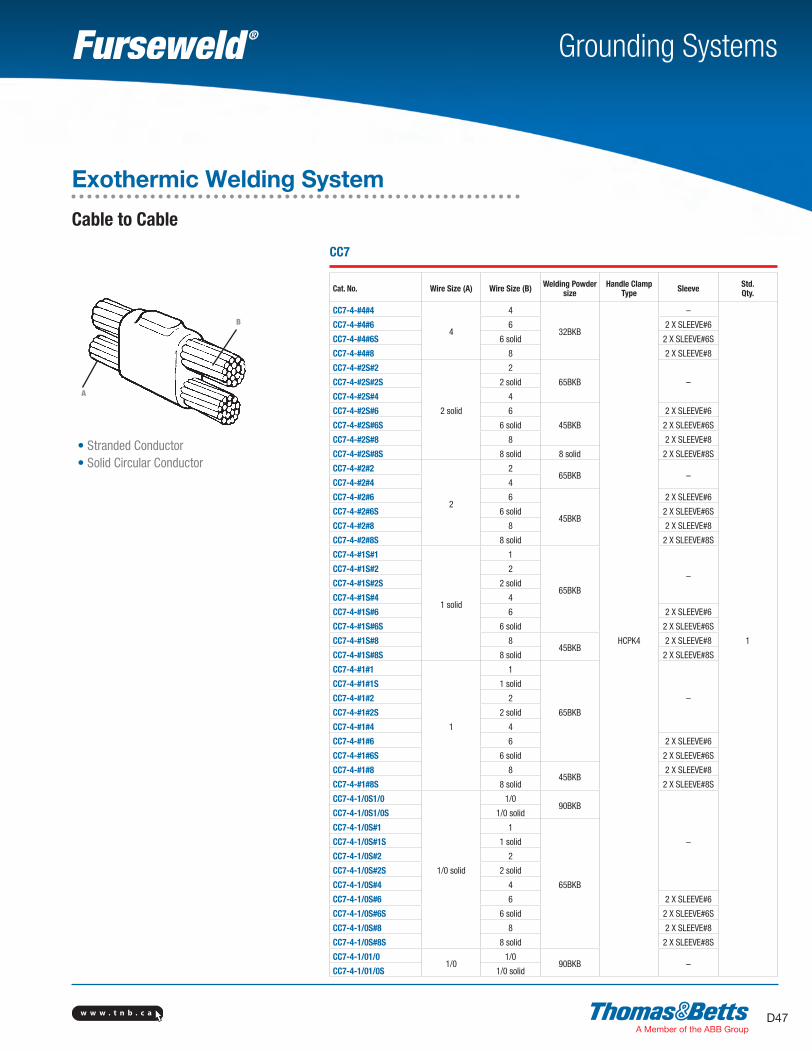
w w w . t n b . c a D47
Grounding Systems
B
• Stranded Conductor• Solid Circular Conductor
A
CC7
Cat. No. Wire Size (A) Wire Size (B) Welding Powder size
Handle Clamp Type Sleeve Std.
Qty.
CC7-4-#4#4
4
4
32BKB
HCPK4
–
1
CC7-4-#4#6 6 2 X SLEEVE#6
CC7-4-#4#6S 6 solid 2 X SLEEVE#6S
CC7-4-#4#8 8 2 X SLEEVE#8
CC7-4-#2S#2
2 solid
2
65BKB –CC7-4-#2S#2S 2 solid
CC7-4-#2S#4 4
CC7-4-#2S#6 6
45BKB
2 X SLEEVE#6
CC7-4-#2S#6S 6 solid 2 X SLEEVE#6S
CC7-4-#2S#8 8 2 X SLEEVE#8
CC7-4-#2S#8S 8 solid 8 solid 2 X SLEEVE#8S
CC7-4-#2#2
2
265BKB –
CC7-4-#2#4 4
CC7-4-#2#6 6
45BKB
2 X SLEEVE#6
CC7-4-#2#6S 6 solid 2 X SLEEVE#6S
CC7-4-#2#8 8 2 X SLEEVE#8
CC7-4-#2#8S 8 solid 2 X SLEEVE#8S
CC7-4-#1S#1
1 solid
1
65BKB
–CC7-4-#1S#2 2
CC7-4-#1S#2S 2 solid
CC7-4-#1S#4 4
CC7-4-#1S#6 6 2 X SLEEVE#6
CC7-4-#1S#6S 6 solid 2 X SLEEVE#6S
CC7-4-#1S#8 845BKB
2 X SLEEVE#8
CC7-4-#1S#8S 8 solid 2 X SLEEVE#8S
CC7-4-#1#1
1
1
65BKB
–
CC7-4-#1#1S 1 solid
CC7-4-#1#2 2
CC7-4-#1#2S 2 solid
CC7-4-#1#4 4
CC7-4-#1#6 6 2 X SLEEVE#6
CC7-4-#1#6S 6 solid 2 X SLEEVE#6S
CC7-4-#1#8 845BKB
2 X SLEEVE#8
CC7-4-#1#8S 8 solid 2 X SLEEVE#8S
CC7-4-1/0S1/0
1/0 solid
1/090BKB
–
CC7-4-1/0S1/0S 1/0 solid
CC7-4-1/0S#1 1
65BKB
CC7-4-1/0S#1S 1 solid
CC7-4-1/0S#2 2
CC7-4-1/0S#2S 2 solid
CC7-4-1/0S#4 4
CC7-4-1/0S#6 6 2 X SLEEVE#6
CC7-4-1/0S#6S 6 solid 2 X SLEEVE#6S
CC7-4-1/0S#8 8 2 X SLEEVE#8
CC7-4-1/0S#8S 8 solid 2 X SLEEVE#8S
CC7-4-1/01/01/0
1/090BKB –
CC7-4-1/01/0S 1/0 solid
Exothermic Welding System
Cable to Cable
SectionD-grounding-systems.indd 47 6/6/2017 9:43:52 AM
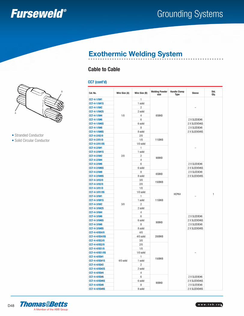
w w w . t n b . c aD48
Grounding Systems
• Stranded Conductor• Solid Circular Conductor
CC7 (cont’d)
Cat. No. Wire Size (A) Wire Size (B) Welding Powder size
Handle Clamp Type Sleeve Std.
Qty.
CC7-4-1/0#1
1/0
1
65BKB
HCPK4
–
1
CC7-4-1/0#1S 1 solid
CC7-4-1/0#2 2
CC7-4-1/0#2S 2 solid
CC7-4-1/0#4 4
CC7-4-1/0#6 6 2 X SLEEVE#6
CC7-4-1/0#6S 6 solid 2 X SLEEVE#6S
CC7-4-1/0#8 8 2 X SLEEVE#8
CC7-4-1/0#8S 8 solid 2 X SLEEVE#8S
CC7-4-2/02/0
2/0
2/0
115BKB
–
CC7-4-2/01/0 1/0
CC7-4-2/01/0S 1/0 solid
CC7-4-2/0#1 1
90BKB
CC7-4-2/0#1S 1 solid
CC7-4-2/0#2 2
CC7-4-2/0#4 4
CC7-4-2/0#6 6 2 X SLEEVE#6
CC7-4-2/0#6S 6 solid 2 X SLEEVE#6S
CC7-4-2/0#8 865BKB
2 X SLEEVE#8
CC7-4-2/0#8S 8 solid 2 X SLEEVE#8S
CC7-4-3/03/0
3/0
3/0150BKB
–
CC7-4-3/02/0 2/0
CC7-4-3/01/0 1/0
115BKB
CC7-4-3/01/0S 1/0 solid
CC7-4-3/0#1 1
CC7-4-3/0#1S 1 solid
CC7-4-3/0#2 2
CC7-4-3/0#2S 2 solid
CC7-4-3/0#4 4
CC7-4-3/0#6 6
90BKB
2 X SLEEVE#6
CC7-4-3/0#6S 6 solid 2 X SLEEVE#6S
CC7-4-3/0#8 8 2 X SLEEVE#8
CC7-4-3/0#8S 8 solid 2 X SLEEVE#8S
CC7-4-4/0S4/0
4/0 solid
4/0
200BKB
–
CC7-4-4/0S4/0S 4/0 solid
CC7-4-4/0S3/0 3/0
CC7-4-4/0S2/0 2/0
150BKB
CC7-4-4/0S1/0 1/0
CC7-4-4/0S1/0S 1/0 solid
CC7-4-4/0S#1 1
CC7-4-4/0S#1S 1 solid
CC7-4-4/0S#2 2
CC7-4-4/0S#2S 2 solid
CC7-4-4/0S#4 4
CC7-4-4/0S#6 6
90BKB
2 X SLEEVE#6
CC7-4-4/0S#6S 6 solid 2 X SLEEVE#6S
CC7-4-4/0S#8 8 2 X SLEEVE#8
CC7-4-4/0S#8S 8 solid 2 X SLEEVE#8S
Cable to Cable
Exothermic Welding System
B
A
SectionD-grounding-systems.indd 48 6/6/2017 9:43:52 AM

w w w . t n b . c a D49
Grounding Systems
• Stranded Conductor• Solid Circular Conductor
CC7 (cont’d)
Cat. No. Wire Size (A) Wire Size (B) Welding Powder size
Handle Clamp Type Sleeve Std.
Qty.
CC7-4-4/04/0
4/0
4/0
200BKB
HCPK4
–
1
CC7-4-4/04/0S 4/0 solid
CC7-4-4/03/0 3/0
CC7-4-4/02/0 2/0
150BKB
CC7-4-4/01/0 1/0
CC7-4-4/01/0S 1/0 solid
CC7-4-4/0#1 1
CC7-4-4/0#1S 1 solid
CC7-4-4/0#2 2
CC7-4-4/0#2S 2 solid
CC7-4-4/0#4 4
CC7-4-4/0#6 6
90BKB
2 X SLEEVE#6
CC7-4-4/0#6S 6 solid 2 X SLEEVE#6S
CC7-4-4/0#8 8 2 X SLEEVE#8
CC7-4-4/0#8S 8 solid 2 X SLEEVE#8S
Cable to Cable
Exothermic Welding System
B
A
SectionD-grounding-systems.indd 49 6/6/2017 9:43:52 AM
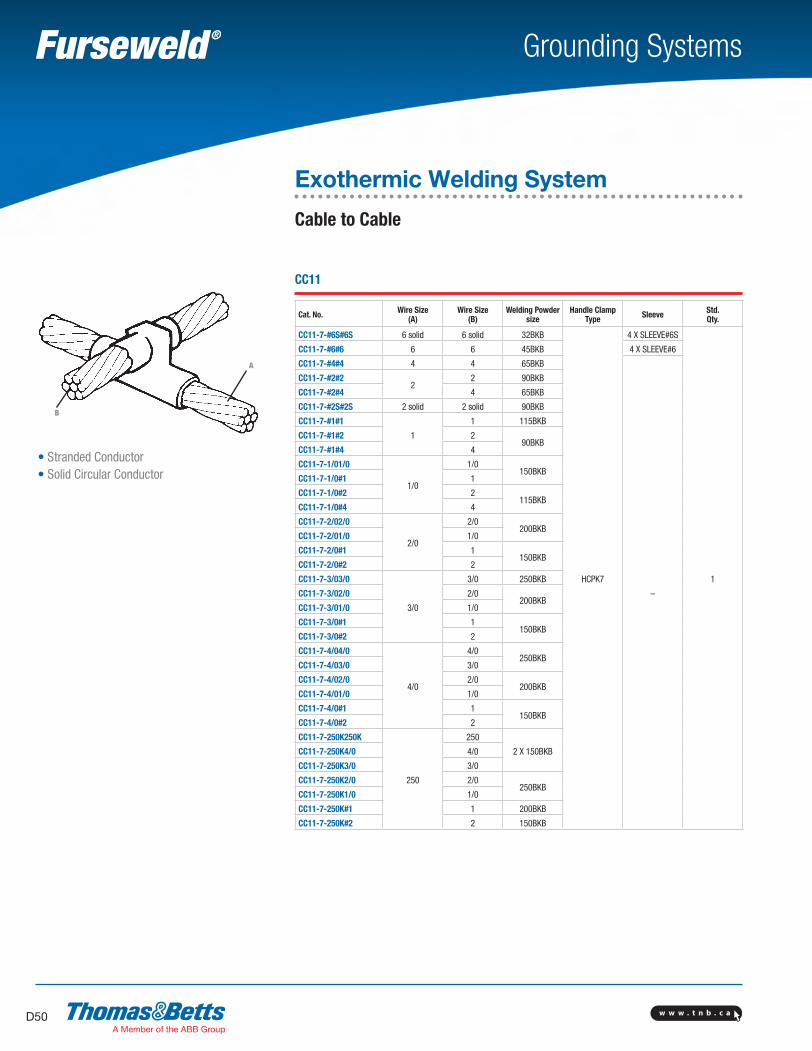
w w w . t n b . c aD50
Grounding Systems
• Stranded Conductor• Solid Circular Conductor
CC11
Cat. No. Wire Size(A)
Wire Size(B)
Welding Powder size
Handle ClampType Sleeve Std.
Qty.
CC11-7-#6S#6S 6 solid 6 solid 32BKB
HCPK7
4 X SLEEVE#6S
1
CC11-7-#6#6 6 6 45BKB 4 X SLEEVE#6
CC11-7-#4#4 4 4 65BKB
–
CC11-7-#2#22
2 90BKB
CC11-7-#2#4 4 65BKB
CC11-7-#2S#2S 2 solid 2 solid 90BKB
CC11-7-#1#1
1
1 115BKB
CC11-7-#1#2 290BKB
CC11-7-#1#4 4
CC11-7-1/01/0
1/0
1/0150BKB
CC11-7-1/0#1 1
CC11-7-1/0#2 2115BKB
CC11-7-1/0#4 4
CC11-7-2/02/0
2/0
2/0200BKB
CC11-7-2/01/0 1/0
CC11-7-2/0#1 1150BKB
CC11-7-2/0#2 2
CC11-7-3/03/0
3/0
3/0 250BKB
CC11-7-3/02/0 2/0200BKB
CC11-7-3/01/0 1/0
CC11-7-3/0#1 1150BKB
CC11-7-3/0#2 2
CC11-7-4/04/0
4/0
4/0250BKB
CC11-7-4/03/0 3/0
CC11-7-4/02/0 2/0200BKB
CC11-7-4/01/0 1/0
CC11-7-4/0#1 1150BKB
CC11-7-4/0#2 2
CC11-7-250K250K
250
250
2 X 150BKBCC11-7-250K4/0 4/0
CC11-7-250K3/0 3/0
CC11-7-250K2/0 2/0250BKB
CC11-7-250K1/0 1/0
CC11-7-250K#1 1 200BKB
CC11-7-250K#2 2 150BKB
Exothermic Welding System
Cable to Cable
A
B
SectionD-grounding-systems.indd 50 6/6/2017 9:43:53 AM
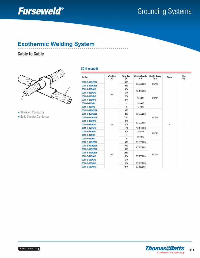
w w w . t n b . c a D51
Grounding Systems
• Stranded Conductor• Solid Circular Conductor
CC11 (cont’d)
Cat. No. Wire Size(A)
Wire Size(B)
Welding Powder size
Handle ClampType Sleeve Std.
Qty.
CC11-8-300K300K
300
3002 X 200BKB HCPK8
– 1
CC11-8-300K250K 250
CC11-7-300K4/0 4/02 X 150BKB
HCPK7
CC11-7-300K3/0 3/0
CC11-7-300K2/0 2/0250BKB
CC11-7-300K1/0 1/0
CC11-7-300K#1 1 200BKB
CC11-7-300K#2 2 150BKB
CC11-8-350K350K
350
350
2 X 250BKB
HCPK8
CC11-8-350K300K 300
CC11-8-350K250K 250
CC11-8-350K4/0 4/02 X 200BKB
CC11-8-350K3/0 3/0
CC11-7-350K2/0 2/0 2 X 150BKB
HCPK7CC11-7-350K1/0 1/0 250BKB
CC11-7-350K#1 1200BKB
CC11-7-350K#2 2
CC11-8-500K500K
500
500 3 X 250BKB
HCPK8
CC11-8-500K350K 3503 X 200BKB
CC11-8-500K300K 300
CC11-8-500K250K 250k
2 X 250BKBCC11-8-500K4/0 4/0
CC11-8-500K3/0 3/0
CC11-8-500K2/0 2/0 2 X 200BKB
CC11-8-500K1/0 1/0 2 X 150BKB
Exothermic Welding System
Cable to Cable
A
B
SectionD-grounding-systems.indd 51 6/6/2017 9:43:53 AM
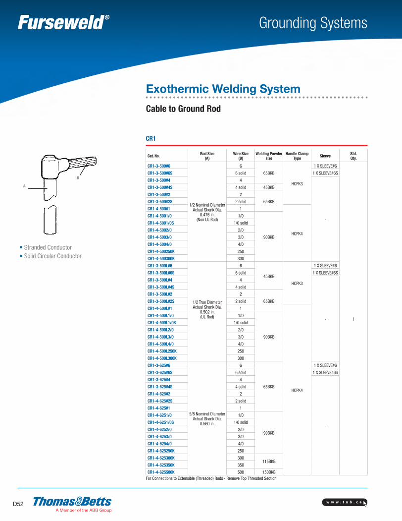
w w w . t n b . c aD52
Grounding Systems
A
B
• Stranded Conductor• Solid Circular Conductor
CR1
Cat. No. Rod Size(A)
Wire Size(B)
Welding Powder size
Handle ClampType Sleeve Std.
Qty.
CR1-3-500#6
1/2 Nominal Diameter Actual Shank Dia.
0.476 in. (Non UL Rod)
6
65BKB
HCPK3
1 X SLEEVE#6
1
CR1-3-500#6S 6 solid 1 X SLEEVE#6S
CR1-3-500#4 4
-
CR1-3-500#4S 4 solid 45BKB
CR1-3-500#2 2
65BKBCR1-3-500#2S 2 solid
CR1-4-500#1 1
HCPK4
CR1-4-5001/0 1/0
90BKB
CR1-4-5001/0S 1/0 solid
CR1-4-5002/0 2/0
CR1-4-5003/0 3/0
CR1-4-5004/0 4/0
CR1-4-500250K 250
CR1-4-500300K 300
CR1-3-500L#6
1/2 True Diameter Actual Shank Dia.
0.502 in. (UL Rod)
6
45BKB
HCPK3
1 X SLEEVE#6
CR1-3-500L#6S 6 solid 1 X SLEEVE#6S
CR1-3-500L#4 4
-
CR1-3-500L#4S 4 solid
CR1-3-500L#2 2
65BKBCR1-3-500L#2S 2 solid
CR1-4-500L#1 1
HCPK4
CR1-4-500L1/0 1/0
90BKB
CR1-4-500L1/0S 1/0 solid
CR1-4-500L2/0 2/0
CR1-4-500L3/0 3/0
CR1-4-500L4/0 4/0
CR1-4-500L250K 250
CR1-4-500L300K 300
CR1-3-625#6
5/8 Nominal Diameter Actual Shank Dia.
0.560 in.
6
65BKB
1 X SLEEVE#6
CR1-3-625#6S 6 solid 1 X SLEEVE#6S
CR1-3-625#4 4
-
CR1-3-625#4S 4 solid
CR1-4-625#2 2
CR1-4-625#2S 2 solid
CR1-4-625#1 1
CR1-4-6251/0 1/0
90BKB
CR1-4-6251/0S 1/0 solid
CR1-4-6252/0 2/0
CR1-4-6253/0 3/0
CR1-4-6254/0 4/0
CR1-4-625250K 250
CR1-4-625300K 300115BKB
CR1-4-625350K 350
CR1-4-625500K 500 150BKBFor Connections to Extensible (Threaded) Rods - Remove Top Threaded Section.
Exothermic Welding System
Cable to Ground Rod
SectionD-grounding-systems.indd 52 6/6/2017 9:43:53 AM
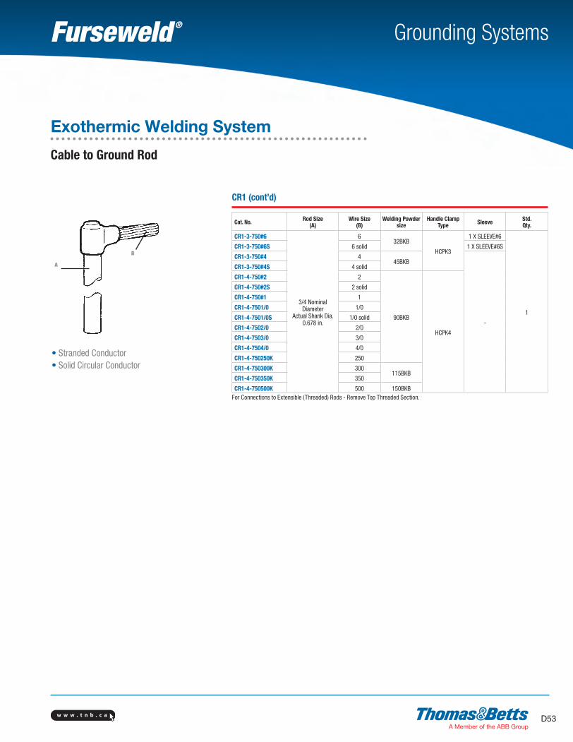
w w w . t n b . c a D53
Grounding Systems
• Stranded Conductor• Solid Circular Conductor
CR1 (cont’d)
Cat. No. Rod Size(A)
Wire Size(B)
Welding Powder size
Handle ClampType Sleeve Std.
Qty.
CR1-3-750#6
3/4 Nominal Diameter
Actual Shank Dia. 0.678 in.
632BKB
HCPK3
1 X SLEEVE#6
1
CR1-3-750#6S 6 solid 1 X SLEEVE#6S
CR1-3-750#4 445BKB
-
CR1-3-750#4S 4 solid
CR1-4-750#2 2
90BKB
HCPK4
CR1-4-750#2S 2 solid
CR1-4-750#1 1
CR1-4-7501/0 1/0
CR1-4-7501/0S 1/0 solid
CR1-4-7502/0 2/0
CR1-4-7503/0 3/0
CR1-4-7504/0 4/0
CR1-4-750250K 250
CR1-4-750300K 300115BKB
CR1-4-750350K 350
CR1-4-750500K 500 150BKBFor Connections to Extensible (Threaded) Rods - Remove Top Threaded Section.
Exothermic Welding System
Cable to Ground Rod
A
B
SectionD-grounding-systems.indd 53 6/6/2017 9:43:53 AM
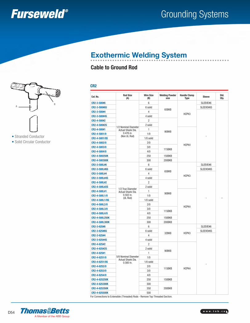
w w w . t n b . c aD54
Grounding Systems
BA
• Stranded Conductor• Solid Circular Conductor
CR2
Cat. No. Rod Size(A)
Wire Size(B)
Welding Powder size
Handle ClampType Sleeve Std.
Qty.
CR2-3-500#6
1/2 Nominal Diameter Actual Shank Dia.
0.476 in. (Non UL Rod)
6
65BKB
HCPK3
SLEEVE#6
–
CR2-3-500#6S 6 solid SLEEVE#6S
CR2-3-500#4 4
-
CR2-3-500#4S 4 solid
CR2-4-500#2 2
90BKB
CR2-4-500#2S 2 solid
CR2-4-500#1 1
HCPK4
CR2-4-5001/0 1/0
CR2-4-5001/0S 1/0 solid
CR2-4-5002/0 2/0
CR2-4-5003/0 3/0115BKB
CR2-4-5004/0 4/0
CR2-4-500250K 250 150BKB
CR2-4-500300K 300 200BKB
CR2-3-500L#6
1/2 True Diameter Actual Shank Dia.
0.502 in. (UL Rod)
6
65BKB
HCPK3
SLEEVE#6
CR2-3-500L#6S 6 solid SLEEVE#6S
CR2-3-500L#4 4
-
CR2-3-500L#4S 4 solid
CR2-4-500L#2 2
90BKB
CR2-4-500L#2S 2 solid
CR2-4-500L#1 1
HCPK4
CR2-4-500L1/0 1/0
CR2-4-500L1/0S 1/0 solid
CR2-4-500L2/0 2/0
CR2-4-500L3/0 3/0115BKB
CR2-4-500L4/0 4/0
CR2-4-500L250K 250 150BKB
CR2-4-500L300K 300 200BKB
CR2-3-625#6
5/8 Nominal Diameter Actual Shank Dia.
0.560 in.
6
32BKB HCPK3
SLEEVE#6
CR2-3-625#6S 6 solid SLEEVE#6S
CR2-3-625#4 4
-
CR2-3-625#4S 4 solid
CR2-4-625#2 2
90BKB
HCPK4
CR2-4-625#2S 2 solid
CR2-4-625#1 1
CR2-4-6251/0 1/0
CR2-4-6251/0S 1/0 solid
115BKBCR2-4-6252/0 2/0
CR2-4-6253/0 3/0
CR2-4-6254/0 4/0
CR2-4-625250K 250 150BKB
CR2-4-625300K 300
200BKBCR2-4-625350K 350
CR2-4-625500K 500For Connections to Extensible (Threaded) Rods - Remove Top Threaded Section.
Exothermic Welding System
Cable to Ground Rod
SectionD-grounding-systems.indd 54 6/6/2017 9:43:54 AM
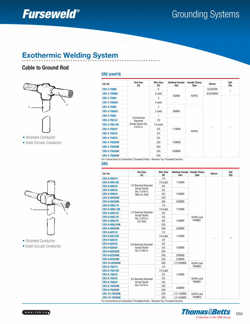
w w w . t n b . c a D55
Grounding Systems
• Stranded Conductor• Solid Circular Conductor
B
A
• Stranded Conductor• Solid Circular Conductor
CR2 (cont’d)
Cat. No. Rod Size(A)
Wire Size(B)
Welding Powder size
Handle ClampType Sleeve Std.
Qty.CR2-3-750#6
3/4 Nominal Diameter
Actual Shank Dia. 0.678 in.
6
65BKB HCPK3
SLEEVE#61
CR2-3-750#6S 6 solid SLEEVE#6S
CR2-3-750#4 4
– –
CR2-3-750#4S 4 solid
CR2-4-750#2 2
90BKB
HCPK4
CR2-4-750#2S 2 solid
CR2-4-750#1 1
CR2-4-7501/0 1/0
115BKB
CR2-4-7501/0S 1/0 solid
CR2-4-7502/0 2/0
CR2-4-7503/0 3/0
CR2-4-7504/0 4/0
CR2-4-750250K 250 150BKB
CR2-4-750300K 300
200BKBCR2-4-750350K 350
CR2-4-750500K 500 For Connections to Extensible (Threaded) Rods - Remove Top Threaded Section.
CR3
Cat. No. Rod Size(A)
Wire Size(B)
Welding Powder size
Handle ClampType Sleeve Std.
Qty.CR3-9-5001/0
1/2 Nominal Diameter Actual Shank Dia. 0.476 in.(Non UL Rod)
1/0115BKB
HCPK4 and FRAME1
– 1
CR3-9-5001/0S 1/0 solidCR3-9-5002/0 2/0CR3-9-5003/0 3/0
150BKBCR3-9-5004/0 4/0CR3-9-500250K 250CR3-9-500300K 300 200BKBCR3-9-500L1/0
1/2 Nominal Diameter Actual Shank Dia. 0.502 in.
(UL Rod)
1/0115BKBCR3-9-500L1/0S 1/0 solid
CR3-9-500L2/0 2/0CR3-9-500L3/0 3/0
150BKBCR3-9-500L4/0 4/0CR3-9-500L250K 250CR3-9-500300K 300 200BKBCR3-9-6251/0
5/8 Nominal Diameter Actual Shank Dia. 0.560 in.
1/0115BKBCR3-9-6251/0S 1/0 solid
CR3-9-6252/0 2/0CR3-9-6253/0 3/0
150BKBCR3-9-6254/0 4/0CR3-9-625250K 250CR3-9-625300K 300 200BKBCR3-9-625350K 350 250BKBCR3-10-625500K 500 2 X 200BKB HCPK5 and
FRAME2CR3-9-7501/0
3/4 Nominal Diameter Actual Shank Dia. 0.678 in.
1/0
115BKBCR3-9-7501/0S 1/0 solid
HCPK4 and FRAME1
CR3-9-7502/0 2/0CR3-9-7503/0 3/0CR3-9-7504/0 4/0CR3-9-750250K 250
200BKBCR3-9-750300K 300CR3-10-750350K 350 2 X 150BKB HCPK5 and
FRAME2CR3-10-750500K 500 2 X 250BKB For Connections to Extensible (Threaded) Rods - Remove Top Threaded Section.
Exothermic Welding System
Cable to Ground Rod
BA
SectionD-grounding-systems.indd 55 6/6/2017 9:43:54 AM
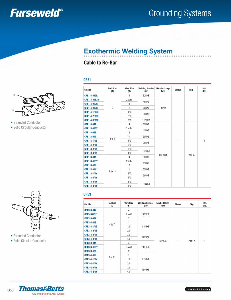
w w w . t n b . c aD56
Grounding Systems
A
B
• Stranded Conductor• Solid Circular Conductor
A
B
• Stranded Conductor• Solid Circular Conductor
CRE1
Cat. No. Rod Size(A)
Wire Size(B)
Welding Powder size
Handle ClampType Sleeve Pkg. Std.
Qty.
CRE1-4-#43R
3
4 32BKB
HCPK4
–
–
1
CRE1-4-#2S3R 2 solid45BKB
CRE1-4-#23R 2
CRE1-4-#13R 1 65BKB
CRE1-4-1/03R 1/090BKB
CRE1-4-2/03R 2/0
CRE1-4-3/03R 3/0 115BKB
CRE1-3-#4Z
4 to 7
4 32BKB
HCPK3B Pack-A
CRE1-3-#2SZ 2 solid45BKB
CRE1-3-#2Z 2
CRE1-3-#1Z 1 65BKB
CRE1-3-1/0Z 1/090BKB
CRE1-3-2/0Z 2/0
CRE1-3-3/0Z 3/0115BKB
CRE1-3-4/0Z 4/0
CRE1-3-#4Y
8 to 11
4 32BKB
CRE1-3-#2SY 2 solid45BKB
CRE1-3-#2Y 2
CRE1-3-#1Y 1 65BKB
CRE1-3-1/0Y 1/090BKB
CRE1-3-2/0Y 2/0
CRE1-3-3/0Y 3/0115BKB
CRE1-3-4/0Y 4/0
CRE3
Cat. No. Rod Size(A)
Wire Size(B)
Welding Powder size
Handle ClampType Sleeve Pkg. Std.
Qty.
CRE3-3-#4Z
4 to 7
4
90BKB
HCPK3A – Pack-A 1
CRE3-3#2SZ 2 solid
CRE3-3-#2Z 2
CRE3-4-#1Z 1
115BKBCRE3-4-1/0Z 1/0
CRE3-4-2/0Z 2/0
CRE3-4-3/0Z 3/0150BKB
CRE3-4-4/0Z 4/0
CRE3-3-#4Y
8 to 11
4
90BKBCRE3-3-#2SY 2 solid
CRE3-3-#2Y 2
CRE3-4-#1Y 1
115BKBCRE3-4-1/0Y 1/0
CRE3-4-2/0Y 2/0
CRE3-4-3/0Y 3/0150BKB
CRE3-4-4/0Y 4/0
Exothermic Welding System
Cable to Re-Bar
SectionD-grounding-systems.indd 56 6/6/2017 9:43:55 AM
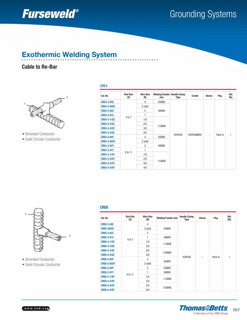
w w w . t n b . c a D57
Grounding Systems
A
B
• Stranded Conductor• Solid Circular Conductor
A
B
• Stranded Conductor• Solid Circular Conductor
CRE4
Cat. No. Rod Size(A)
Wire Size(B)
Welding Powder size
Handle ClampType Cradle Sleeve Pkg. Std.
Qty.
CRE4-3-#4Z
4 to 7
4 65BKB
HCPK3B HCPK3BMOD - Pack-A 1
CRE4-3-#2SZ 2 solid
90BKBCRE4-3-#2Z 2
CRE4-3-#1Z 1
CRE4-3-1/OZ 1/0
115BKBCRE4-3-2/0Z 2/0
CRE4-3-3/0Z 3/0
CRE4-3-4/0Z 4/0
CRE4-3-#4Y
8 to 11
4 65BKB
CRE4-3-#2SY 2 solid
90BKBCRE4-3-#2Y 2
CRE4-3-#1Y 1
CRE4-3-1/0Y 1/0
115BKBCRE4-3-2/0Y 2/0
CRE4-3-3/0Y 3/0
CRE4-3-4/0Y 4/0
CRE6
Cat. No. Rod Size(A)
Wire Size(B) Welding Powder size Handle Clamp
Type Sleeve Pkg. Std. Qty.
CRE6-3-#4Z
4 to 7
4
65BKB
HCPK3A – Pack-A 1
CRE6-3#2SZ 2 solid
CRE6-3-#2Z 2
CRE6-3-#1Z 1 90BKB
CRE6-4-1/0Z 1/0115BKB
CRE6-4-2/0Z 2/0
CRE6-4-3/0Z 3/0150BKB
CRE6-4-4/0Z 4/0
CRE6-3-#4Y
8 to 11
465BKB
CRE6-3-#2SY 2 solid
CRE6-3-#2Y 2 65BKB
CRE6-3-#1Y 1 90BKB
CRE6-4-1/0Y 1/0115BKB
CRE6-4-2/0Y 2/0
CRE6-4-3/0Y 3/0150BKB
CRE6-4-4/0Y 4/0
Exothermic Welding System
Cable to Re-Bar
SectionD-grounding-systems.indd 57 6/6/2017 9:43:56 AM
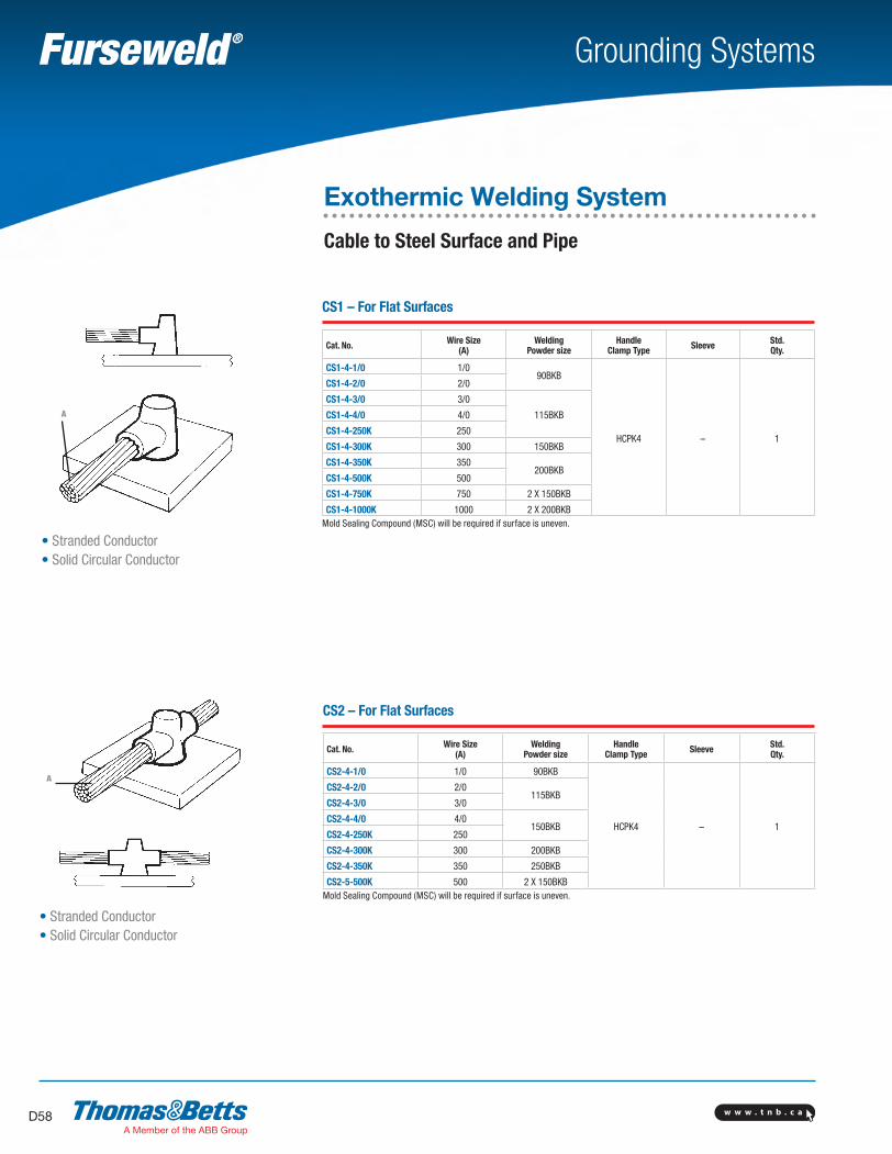
w w w . t n b . c aD58
Grounding Systems
• Stranded Conductor• Solid Circular Conductor
A
• Stranded Conductor• Solid Circular Conductor
CS1 – For Flat Surfaces
Cat. No. Wire Size(A)
Welding Powder size
Handle Clamp Type Sleeve Std.
Qty.
CS1-4-1/0 1/090BKB
HCPK4 – 1
CS1-4-2/0 2/0
CS1-4-3/0 3/0
115BKBCS1-4-4/0 4/0
CS1-4-250K 250
CS1-4-300K 300 150BKB
CS1-4-350K 350200BKB
CS1-4-500K 500
CS1-4-750K 750 2 X 150BKB
CS1-4-1000K 1000 2 X 200BKBMold Sealing Compound (MSC) will be required if surface is uneven.
CS2 – For Flat Surfaces
Cat. No. Wire Size(A)
Welding Powder size
Handle Clamp Type Sleeve Std.
Qty.
CS2-4-1/0 1/0 90BKB
HCPK4 – 1
CS2-4-2/0 2/0115BKB
CS2-4-3/0 3/0
CS2-4-4/0 4/0150BKB
CS2-4-250K 250
CS2-4-300K 300 200BKB
CS2-4-350K 350 250BKB
CS2-5-500K 500 2 X 150BKBMold Sealing Compound (MSC) will be required if surface is uneven.
Exothermic Welding System
Cable to Steel Surface and Pipe
A
SectionD-grounding-systems.indd 58 6/6/2017 9:43:56 AM
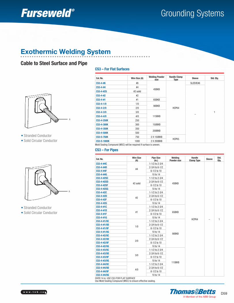
w w w . t n b . c a D59
Grounding Systems
A
• Stranded Conductor• Solid Circular Conductor
A
• Stranded Conductor• Solid Circular Conductor
CS3 – For Flat Surfaces
Cat. No. Wire Size (A) Welding Powder size
Handle Clamp Type Sleeve Std. Qty.
CS3-4-#6 #6
45BKB
HCPK4
SLEEVE#6
1
CS3-4-#4 #4
–
CS3-4-#2S #2 solid
CS3-4-#2 #2
CS3-4-#1 #1 65BKB
CS3-4-1/0 1/090BKB
CS3-4-2/0 2/0
CS3-4-3/0 3/0
115BKBCS3-4-4/0 4/0
CS3-4-250K 250
CS3-4-300K 300 150BKB
CS3-4-350K 350200BKB
CS3-4-500K 500
CS3-5-750K 750 2 X 150BKBHCPK5
CS3-5-1000K 1000 2 X 200BKBMold Sealing Compound (MSC) will be required if surface is uneven.
CS3 – For Pipes
Cat. No. Wire Size(A)
Pipe Size(in.)
Welding Powder size
Handle Clamp Type Sleeve Std.
Qty.CS3-4-#4C
#4
1-1/2 to 2-3/4
45BKB
HCPK4 – 1
CS3-4-#4D 2-3/4 to 6-1/2CS3-4-#4F 6-1/2 to 10CS3-4-#4G 10 to 14CS3-4-#2SC
#2 solid
1-1/2 to 2-3/4CS3-4-#2SD 2-3/4 to 6-1/2CS3-4-#2SF 6-1/2 to 10CS3-4-#2SG 10 to 14CS3-4-#2C
#2
1-1/2 to 2-3/4CS3-4-#2D 2-3/4 to 6-1/2CS3-4-#2F 6-1/2 to 10CS3-4-#2G 10 to 14CS3-4-#1C
#1
1-1/2 to 2-3/4
65BKBCS3-4-#1D 2-3/4 to 6-1/2CS3-4-#1F 6-1/2 to 10CS3-4-#1G 10 to 14CS3-4-#1/0C
1/0
1-1/2 to 2-3/4
90BKB
CS3-4-#1/0D 2-3/4 to 6-1/2CS3-4-#1/0F 6-1/2 to 10CS3-4-#1/0G 10 to 14CS3-4-#2/0C
2/0
1-1/2 to 2-3/4CS3-4-#2/0D 2-3/4 to 6-1/2CS3-4-#2/0F 6-1/2 to 10CS3-4-#2/0G 10 to 14CS3-4-#3/0C
3/0
1-1/2 to 2-3/4
115BKB
CS3-4-#3/0D 2-3/4 to 6-1/2CS3-4-#3/0F 6-1/2 to 10CS3-4-#3/0G 10 to 14CS3-4-#4/0C
4/0
1-1/2 to 2-3/4CS3-4-#4/0D 2-3/4 to 6-1/2CS3-4-#4/0F 6-1/2 to 10CS3-4-#4/0G 10 to 14
OVER 14 in. USE CS3 FOR FLAT SURFACEUse Mold Sealing Compound (MSC) to ensure effective sealing.
Exothermic Welding System
Cable to Steel Surface and Pipe
SectionD-grounding-systems.indd 59 6/6/2017 9:43:57 AM
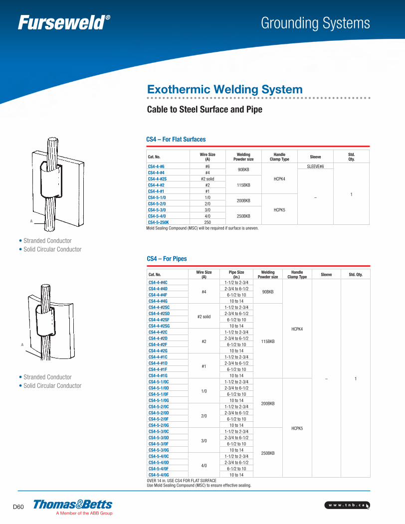
w w w . t n b . c aD60
Grounding Systems
CS4 – For Flat Surfaces
Cat. No. Wire Size(A)
Welding Powder size
Handle Clamp Type Sleeve Std.
Qty.
CS4-4-#6 #690BKB
HCPK4
SLEEVE#6
1
CS4-4-#4 #4
–
CS4-4-#2S #2 solid115BKBCS4-4-#2 #2
CS4-4-#1 #1CS4-5-1/0 1/0
200BKB
HCPK5CS4-5-2/0 2/0CS4-5-3/0 3/0
250BKBCS4-5-4/0 4/0CS4-5-250K 250
Mold Sealing Compound (MSC) will be required if surface is uneven.
A
• Stranded Conductor• Solid Circular Conductor
A
• Stranded Conductor• Solid Circular Conductor
CS4 – For Pipes
Cat. No. Wire Size(A)
Pipe Size(in.)
Welding Powder size
Handle Clamp Type Sleeve Std. Qty.
CS4-4-#4C
#4
1-1/2 to 2-3/4
90BKB
HCPK4
– 1
CS4-4-#4D 2-3/4 to 6-1/2CS4-4-#4F 6-1/2 to 10CS4-4-#4G 10 to 14CS4-4-#2SC
#2 solid
1-1/2 to 2-3/4
115BKB
CS4-4-#2SD 2-3/4 to 6-1/2CS4-4-#2SF 6-1/2 to 10CS4-4-#2SG 10 to 14CS4-4-#2C
#2
1-1/2 to 2-3/4CS4-4-#2D 2-3/4 to 6-1/2CS4-4-#2F 6-1/2 to 10CS4-4-#2G 10 to 14CS4-4-#1C
#1
1-1/2 to 2-3/4CS4-4-#1D 2-3/4 to 6-1/2CS4-4-#1F 6-1/2 to 10CS4-4-#1G 10 to 14CS4-5-1/0C
1/0
1-1/2 to 2-3/4
200BKB
HCPK5
CS4-5-1/0D 2-3/4 to 6-1/2CS4-5-1/0F 6-1/2 to 10CS4-5-1/0G 10 to 14CS4-5-2/0C
2/0
1-1/2 to 2-3/4CS4-5-2/0D 2-3/4 to 6-1/2CS4-5-2/0F 6-1/2 to 10CS4-5-2/0G 10 to 14CS4-5-3/0C
3/0
1-1/2 to 2-3/4
250BKB
CS4-5-3/0D 2-3/4 to 6-1/2CS4-5-3/0F 6-1/2 to 10CS4-5-3/0G 10 to 14CS4-5-4/0C
4/0
1-1/2 to 2-3/4CS4-5-4/0D 2-3/4 to 6-1/2CS4-5-4/0F 6-1/2 to 10CS4-5-4/0G 10 to 14
OVER 14 in. USE CS4 FOR FLAT SURFACEUse Mold Sealing Compound (MSC) to ensure effective sealing.
Exothermic Welding System
Cable to Steel Surface and Pipe
SectionD-grounding-systems.indd 60 6/6/2017 9:43:58 AM
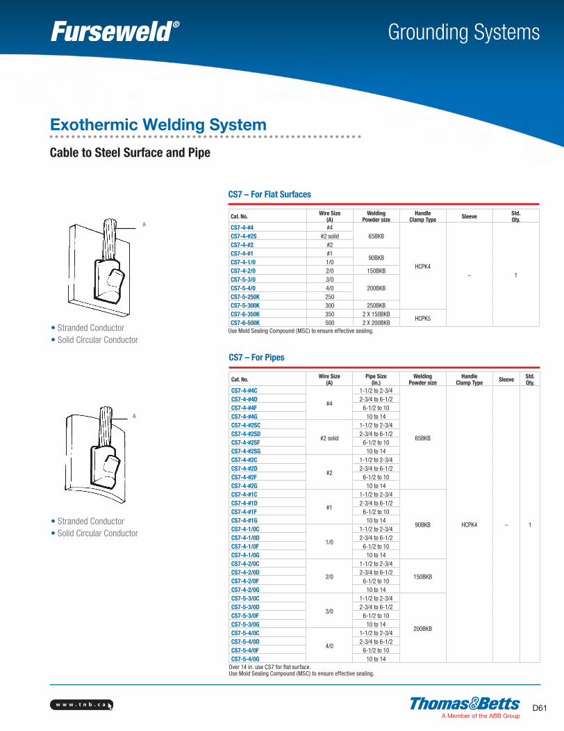
w w w . t n b . c a D61
Grounding Systems
CS7 – For Flat Surfaces
Cat. No. Wire Size(A)
Welding Powder size
Handle Clamp Type Sleeve Std.
Qty.CS7-4-#4 #4
65BKB
HCPK4– 1
CS7-4-#2S #2 solidCS7-4-#2 #2CS7-4-#1 #1
90BKBCS7-4-1/0 1/0CS7-4-2/0 2/0 150BKBCS7-5-3/0 3/0
200BKBCS7-5-4/0 4/0CS7-5-250K 250CS7-5-300K 300 250BKBCS7-6-350K 350 2 X 150BKB
HCPK5CS7-6-500K 500 2 X 200BKB
Use Mold Sealing Compound (MSC) to ensure effective sealing.
CS7 – For Pipes
Cat. No. Wire Size(A)
Pipe Size(in.)
Welding Powder size
Handle Clamp Type Sleeve Std.
Qty.CS7-4-#4C
#4
1-1/2 to 2-3/4
65BKB
HCPK4 – 1
CS7-4-#4D 2-3/4 to 6-1/2CS7-4-#4F 6-1/2 to 10CS7-4-#4G 10 to 14CS7-4-#2SC
#2 solid
1-1/2 to 2-3/4CS7-4-#2SD 2-3/4 to 6-1/2CS7-4-#2SF 6-1/2 to 10CS7-4-#2SG 10 to 14CS7-4-#2C
#2
1-1/2 to 2-3/4CS7-4-#2D 2-3/4 to 6-1/2CS7-4-#2F 6-1/2 to 10CS7-4-#2G 10 to 14CS7-4-#1C
#1
1-1/2 to 2-3/4
90BKB
CS7-4-#1D 2-3/4 to 6-1/2CS7-4-#1F 6-1/2 to 10CS7-4-#1G 10 to 14CS7-4-1/0C
1/0
1-1/2 to 2-3/4CS7-4-1/0D 2-3/4 to 6-1/2CS7-4-1/0F 6-1/2 to 10CS7-4-1/0G 10 to 14CS7-4-2/0C
2/0
1-1/2 to 2-3/4
150BKBCS7-4-2/0D 2-3/4 to 6-1/2CS7-4-2/0F 6-1/2 to 10CS7-4-2/0G 10 to 14CS7-5-3/0C
3/0
1-1/2 to 2-3/4
200BKB
CS7-5-3/0D 2-3/4 to 6-1/2CS7-5-3/0F 6-1/2 to 10CS7-5-3/0G 10 to 14CS7-5-4/0C
4/0
1-1/2 to 2-3/4CS7-5-4/0D 2-3/4 to 6-1/2CS7-5-4/0F 6-1/2 to 10CS7-5-4/0G 10 to 14
Over 14 in. use CS7 for flat surface.Use Mold Sealing Compound (MSC) to ensure effective sealing.
A
• Stranded Conductor• Solid Circular Conductor
A
• Stranded Conductor• Solid Circular Conductor
Exothermic Welding System
Cable to Steel Surface and Pipe
SectionD-grounding-systems.indd 61 6/6/2017 9:43:58 AM
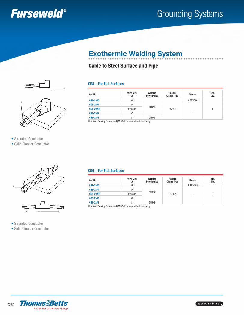
w w w . t n b . c aD62
Grounding Systems
CS8 – For Flat Surfaces
Cat. No. Wire Size(A)
Welding Powder size
Handle Clamp Type Sleeve Std.
Qty.
CS8-2-#6 #6
45BKBHCPK2
SLEEVE#6
1
CS8-2-#4 #4
–CS8-2-#2S #2 solid
CS8-2-#2 #2
CS8-2-#1 #1 65BKBUse Mold Sealing Compound (MSC) to ensure effective sealing.
CS9 – For Flat Surfaces
Cat. No. Wire Size(A)
Welding Powder size
Handle Clamp Type Sleeve Std.
Qty.CS9-2-#6 #6
45BKBHCPK2
SLEEVE#6
1
CS9-2-#4 #4
–CS9-2-#2S #2 solid
CS9-2-#2 #2
CS9-2-#1 #1 65BKBUse Mold Sealing Compound (MSC) to ensure effective sealing.
• Stranded Conductor• Solid Circular Conductor
A
A
• Stranded Conductor• Solid Circular Conductor
Exothermic Welding System
Cable to Steel Surface and Pipe
SectionD-grounding-systems.indd 62 6/6/2017 9:43:59 AM
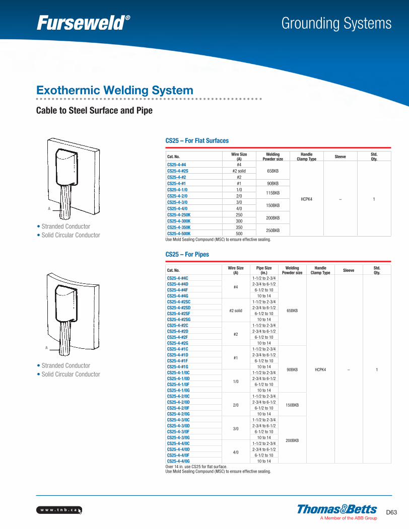
w w w . t n b . c a D63
Grounding Systems
A
• Stranded Conductor• Solid Circular Conductor
A
• Stranded Conductor• Solid Circular Conductor
CS25 – For Flat Surfaces
Cat. No. Wire Size(A)
Welding Powder size
Handle Clamp Type Sleeve Std.
Qty.CS25-4-#4 #4
65BKB
HCPK4 – 1
CS25-4-#2S #2 solidCS25-4-#2 #2CS25-4-#1 #1 90BKBCS25-4-1/0 1/0
115BKBCS25-4-2/0 2/0CS25-4-3/0 3/0
150BKBCS25-4-4/0 4/0CS25-4-250K 250
200BKBCS25-4-300K 300CS25-4-350K 350
250BKBCS25-4-500K 500
Use Mold Sealing Compound (MSC) to ensure effective sealing.
CS25 – For Pipes
Cat. No. Wire Size(A)
Pipe Size(in.)
Welding Powder size
Handle Clamp Type Sleeve Std.
Qty.CS25-4-#4C
#4
1-1/2 to 2-3/4
65BKB
HCPK4 – 1
CS25-4-#4D 2-3/4 to 6-1/2CS25-4-#4F 6-1/2 to 10CS25-4-#4G 10 to 14CS25-4-#2SC
#2 solid
1-1/2 to 2-3/4CS25-4-#2SD 2-3/4 to 6-1/2CS25-4-#2SF 6-1/2 to 10CS25-4-#2SG 10 to 14CS25-4-#2C
#2
1-1/2 to 2-3/4CS25-4-#2D 2-3/4 to 6-1/2CS25-4-#2F 6-1/2 to 10CS25-4-#2G 10 to 14CS25-4-#1C
#1
1-1/2 to 2-3/4
90BKB
CS25-4-#1D 2-3/4 to 6-1/2CS25-4-#1F 6-1/2 to 10CS25-4-#1G 10 to 14CS25-4-1/0C
1/0
1-1/2 to 2-3/4CS25-4-1/0D 2-3/4 to 6-1/2CS25-4-1/0F 6-1/2 to 10CS25-4-1/0G 10 to 14CS25-4-2/0C
2/0
1-1/2 to 2-3/4
150BKBCS25-4-2/0D 2-3/4 to 6-1/2CS25-4-2/0F 6-1/2 to 10CS25-4-2/0G 10 to 14CS25-4-3/0C
3/0
1-1/2 to 2-3/4
200BKB
CS25-4-3/0D 2-3/4 to 6-1/2CS25-4-3/0F 6-1/2 to 10CS25-4-3/0G 10 to 14CS25-4-4/0C
4/0
1-1/2 to 2-3/4CS25-4-4/0D 2-3/4 to 6-1/2CS25-4-4/0F 6-1/2 to 10CS25-4-4/0G 10 to 14
Over 14 in. use CS25 for flat surface.Use Mold Sealing Compound (MSC) to ensure effective sealing.
Exothermic Welding System
Cable to Steel Surface and Pipe
SectionD-grounding-systems.indd 63 6/6/2017 9:43:59 AM
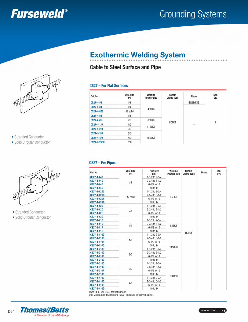
w w w . t n b . c aD64
Grounding Systems
CS27 – For Flat Surfaces
Cat. No. Wire Size(A)
Welding Powder size
Handle Clamp Type Sleeve Std.
Qty.
CS27-4-#6 #6
45BKB
HCPK4
SLEEVE#6
1
CS27-4-#4 #4
–
CS27-4-#2S #2 solid
CS27-4-#2 #2
CS27-4-#1 #1 65BKB
CS27-4-1/0 1/0115BKB
CS27-4-2/0 2/0
CS27-4-3/0 3/0
150BKBCS27-4-4/0 4/0
CS27-4-250K 250
CS27 – For Pipes
Cat. No. Wire Size(A)
Pipe Size(in.)
Welding Powder size
Handle Clamp Type Sleeve Std.
Qty.CS27-4-#4C
#4
1-1/2 to 2-3/4
45BKB
HCPK4 – 1
CS27-4-#4D 2-3/4 to 6-1/2CS27-4-#4F 6-1/2 to 10CS27-4-#4G 10 to 14CS27-4-#2SC
#2 solid
1-1/2 to 2-3/4CS27-4-#2SD 2-3/4 to 6-1/2CS27-4-#2SF 6-1/2 to 10CS27-4-#2SG 10 to 14CS27-4-#2C
#2
1-1/2 to 2-3/4CS27-4-#2D 2-3/4 to 6-1/2CS27-4-#2F 6-1/2 to 10CS27-4-#2G 10 to 14CS27-4-#1C
#1
1-1/2 to 2-3/4
65BKBCS27-4-#1D 2-3/4 to 6-1/2CS27-4-#1F 6-1/2 to 10CS27-4-#1G 10 to 14CS27-4-110C
1/0
1-1/2 to 2-3/4
115BKB
CS27-4-110D 2-3/4 to 6-1/2CS27-4-110F 6-1/2 to 10CS27-4-110G 10 to 14CS27-4-210C
2/0
1-1/2 to 2-3/4CS27-4-210D 2-3/4 to 6-1/2CS27-4-210F 6-1/2 to 10CS27-4-210G 10 to 14CS27-4-310C
3/0
1-1/2 to 2-3/4
150BKB
CS27-4-310D 2-3/4 to 6-1/2CS27-4-310F 6-1/2 to 10CS27-4-310G 10 to 14CS27-4-410C
4/0
1-1/2 to 2-3/4CS27-4-410D 2-3/4 to 6-1/2CS27-4-410F 6-1/2 to 10CS27-4-410G 10 to 14
Over 14 in. use CS27 for flat surface.Use Mold Sealing Compound (MSC) to ensure effective sealing.
A
• Stranded Conductor• Solid Circular Conductor
A
• Stranded Conductor• Solid Circular Conductor
Exothermic Welding System
Cable to Steel Surface and Pipe
SectionD-grounding-systems.indd 64 6/6/2017 9:44:00 AM
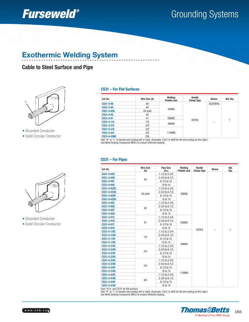
w w w . t n b . c a D65
Grounding Systems
A
• Stranded Conductor• Solid Circular Conductor
A
• Stranded Conductor• Solid Circular Conductor
CS31 – For Flat Surfaces
Cat. No. Wire Size (A) Welding Powder size
Handle Clamp Type Sleeve Std. Qty.
CS31-4-#6 #6
45BKB
HCPK4
SLEEVE#6
1
CS31-4-#4 #4
–
CS31-4-#2S #2 solidCS31-4-#2 #2CS31-4-#1 #1 65BKBCS31-4-1/0 1/0
90BKBCS31-4-2/0 2/0CS31-4-3/0 3/0
115BKBCS31-4-4/0 4/0CS31-4-250K 250
Add “R” or “L” to denote wire exiting left or right. (Example: CS31-6-#6R for #6 wire exiting on the right.)Use Mold Sealing Compound (MSC) to ensure effective sealing.
CS31 – For Pipes
Cat. No. Wire Size(A)
Pipe Size(in.)
Welding Powder size
Handle Clamp Type Sleeve Std.
Qty.CS31-4-#4C
#4
1-1/2 to 2-3/4
45BKB
HCPK4 – 1
CS31-4-#4D 2-3/4 to 6-1/2CS31-4-#4F 6-1/2 to 10CS31-4-#4G 10 to 14CS31-4-#2SC
#2 solid
1-1/2 to 2-3/4CS31-4-#2SD 2-3/4 to 6-1/2CS31-4-#2SF 6-1/2 to 10CS31-4-#2SG 10 to 14CS31-4-#2C
#2
1-1/2 to 2-3/4CS31-4-#2D 2-3/4 to 6-1/2CS31-4-#2F 6-1/2 to 10CS31-4-#2G 10 to 14CS31-4-#1C
#1
1-1/2 to 2-3/4
65BKBCS31-4-#1D 2-3/4 to 6-1/2CS31-4-#1F 6-1/2 to 10CS31-4-#1G 10 to 14CS31-4-1/0C
1/0
1-1/2 to 2-3/4
90BKB
CS31-4-1/0D 2-3/4 to 6-1/2CS31-4-1/0F 6-1/2 to 10CS31-4-1/0G 10 to 14CS31-4-2/0C
2/0
1-1/2 to 2-3/4CS31-4-2/0D 2-3/4 to 6-1/2CS31-4-2/0F 6-1/2 to 10CS31-4-2/0G 10 to 14CS31-4-3/0C
3/0
1-1/2 to 2-3/4
115BKB
CS31-4-3/0D 2-3/4 to 6-1/2CS31-4-3/0F 6-1/2 to 10CS31-4-3/0G 10 to 14CS31-4-4/0C
4/0
1-1/2 to 2-3/4CS31-4-4/0D 2-3/4 to 6-1/2CS31-4-4/0F 6-1/2 to 10CS31-4-4/0G 10 to 14
Over 14 in. use CS31 for flat surface.Add “R” or “L” to denote wire exiting left or right. (Example: CS31-6-#6R for #6 wire exiting on the right.)Use Mold Sealing Compound (MSC) to ensure effective sealing.
Exothermic Welding System
Cable to Steel Surface and Pipe
SectionD-grounding-systems.indd 65 6/6/2017 9:44:00 AM
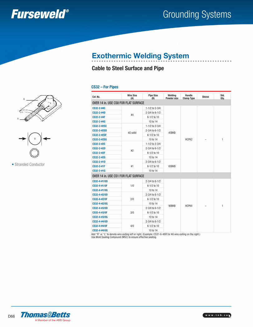
w w w . t n b . c aD66
Grounding Systems
CS32 – For Pipes
Cat. No. Wire Size(A)
Pipe Size(B)
Welding Powder size
Handle Clamp Type Sleeve Std.
Qty.
OVER 14 in. USE CS8 FOR FLAT SURFACECS32-2-#4C
#4
1-1/2 to 2-3/4
45BKB
HCPK2 – 1
CS32-2-#4D 2-3/4 to 6-1/2
CS32-2-#4F 6-1/2 to 10
CS32-2-#4G 10 to 14
CS32-2-#2SC
#2 solid
1-1/2 to 2-3/4
CS32-2-#2SD 2-3/4 to 6-1/2
CS32-2-#2SF 6-1/2 to 10
CS32-2-#2SG 10 to 14
CS32-2-#2C
#2
1-1/2 to 2-3/4
CS32-2-#2D 2-3/4 to 6-1/2
CS32-2-#2F 6-1/2 to 10
CS32-2-#2G 10 to 14
CS32-2-#1D
#1
2-3/4 to 6-1/2
65BKBCS32-2-#1F 6-1/2 to 10
CS32-2-#1G 10 to 14
OVER 14 in. USE CS1 FOR FLAT SURFACECS32-4-#1/0D
1/0
2-3/4 to 6-1/2
90BKB HCPK4 – 1
CS32-4-#1/0F 6-1/2 to 10
CS32-4-#1/0G 10 to 14
CS32-4-#2/0D
2/0
2-3/4 to 6-1/2
CS32-4-#2/0F 6-1/2 to 10
CS32-4-#2/0G 10 to 14
CS32-4-#3/0D
3/0
2-3/4 to 6-1/2
CS32-4-#3/0F 6-1/2 to 10
CS32-4-#3/0G 10 to 14
CS32-4-#4/0D
4/0
2-3/4 to 6-1/2
CS32-4-#4/0F 6-1/2 to 10
CS32-4-#4/0G 10 to 14Add “R” or “L” to denote wire exiting left or right. (Example: CS31-6-#6R for #6 wire exiting on the right.)Use Mold Sealing Compound (MSC) to ensure effective sealing.
A
• Stranded Conductor
B
Exothermic Welding System
Cable to Steel Surface and Pipe
B
SectionD-grounding-systems.indd 66 6/6/2017 9:44:01 AM
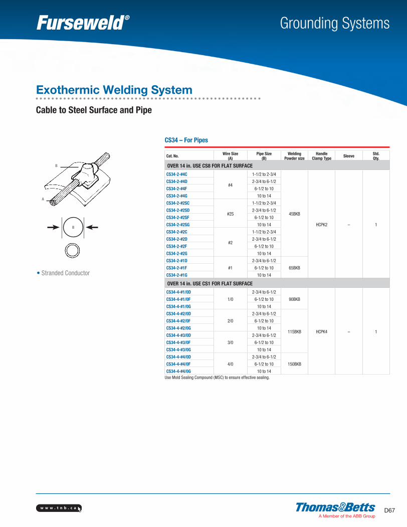
w w w . t n b . c a D67
Grounding Systems
A
B
• Stranded Conductor
CS34 – For Pipes
Cat. No. Wire Size(A)
Pipe Size(B)
Welding Powder size
Handle Clamp Type Sleeve Std.
Qty.
OVER 14 in. USE CS8 FOR FLAT SURFACE
CS34-2-#4C
#4
1-1/2 to 2-3/4
45BKB
HCPK2 – 1
CS34-2-#4D 2-3/4 to 6-1/2
CS34-2-#4F 6-1/2 to 10
CS34-2-#4G 10 to 14
CS34-2-#2SC
#2S
1-1/2 to 2-3/4
CS34-2-#2SD 2-3/4 to 6-1/2
CS34-2-#2SF 6-1/2 to 10
CS34-2-#2SG 10 to 14
CS34-2-#2C
#2
1-1/2 to 2-3/4
CS34-2-#2D 2-3/4 to 6-1/2
CS34-2-#2F 6-1/2 to 10
CS34-2-#2G 10 to 14
CS34-2-#1D
#1
2-3/4 to 6-1/2
65BKBCS34-2-#1F 6-1/2 to 10
CS34-2-#1G 10 to 14
OVER 14 in. USE CS1 FOR FLAT SURFACE
CS34-4-#1/0D
1/0
2-3/4 to 6-1/2
90BKB
HCPK4 – 1
CS34-4-#1/0F 6-1/2 to 10
CS34-4-#1/0G 10 to 14
CS34-4-#2/0D
2/0
2-3/4 to 6-1/2
115BKB
CS34-4-#2/0F 6-1/2 to 10
CS34-4-#2/0G 10 to 14
CS34-4-#3/0D
3/0
2-3/4 to 6-1/2
CS34-4-#3/0F 6-1/2 to 10
CS34-4-#3/0G 10 to 14
CS34-4-#4/0D
4/0
2-3/4 to 6-1/2
150BKBCS34-4-#4/0F 6-1/2 to 10
CS34-4-#4/0G 10 to 14Use Mold Sealing Compound (MSC) to ensure effective sealing.
Exothermic Welding System
Cable to Steel Surface and Pipe
B
SectionD-grounding-systems.indd 67 6/6/2017 9:44:01 AM
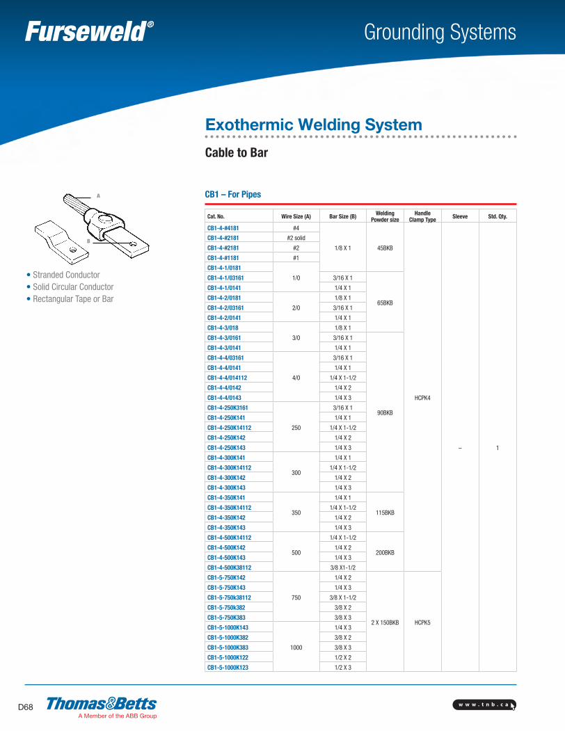
w w w . t n b . c aD68
Grounding Systems
CB1 – For Pipes
Cat. No. Wire Size (A) Bar Size (B) Welding Powder size
Handle Clamp Type Sleeve Std. Qty.
CB1-4-#4181 #4
1/8 X 1 45BKB
HCPK4
– 1
CB1-4-#2181 #2 solid
CB1-4-#2181 #2
CB1-4-#1181 #1
CB1-4-1/0181
1/0CB1-4-1/03161 3/16 X 1
65BKB
CB1-4-1/0141 1/4 X 1
CB1-4-2/0181
2/0
1/8 X 1
CB1-4-2/03161 3/16 X 1
CB1-4-2/0141 1/4 X 1
CB1-4-3/018
3/0
1/8 X 1
CB1-4-3/0161 3/16 X 1
90BKB
CB1-4-3/0141 1/4 X 1
CB1-4-4/03161
4/0
3/16 X 1
CB1-4-4/0141 1/4 X 1
CB1-4-4/014112 1/4 X 1-1/2
CB1-4-4/0142 1/4 X 2
CB1-4-4/0143 1/4 X 3
CB1-4-250K3161
250
3/16 X 1
CB1-4-250K141 1/4 X 1
CB1-4-250K14112 1/4 X 1-1/2
CB1-4-250K142 1/4 X 2
CB1-4-250K143 1/4 X 3
CB1-4-300K141
300
1/4 X 1
CB1-4-300K14112 1/4 X 1-1/2
CB1-4-300K142 1/4 X 2
CB1-4-300K143 1/4 X 3
CB1-4-350K141
350
1/4 X 1
115BKBCB1-4-350K14112 1/4 X 1-1/2
CB1-4-350K142 1/4 X 2
CB1-4-350K143 1/4 X 3
CB1-4-500K14112
500
1/4 X 1-1/2
200BKBCB1-4-500K142 1/4 X 2
CB1-4-500K143 1/4 X 3
CB1-4-500K38112 3/8 X1-1/2
CB1-5-750K142
750
1/4 X 2
2 X 150BKB HCPK5
CB1-5-750K143 1/4 X 3
CB1-5-750k38112 3/8 X 1-1/2
CB1-5-750k382 3/8 X 2
CB1-5-750K383 3/8 X 3
CB1-5-1000K143
1000
1/4 X 3
CB1-5-1000K382 3/8 X 2
CB1-5-1000K383 3/8 X 3
CB1-5-1000K122 1/2 X 2
CB1-5-1000K123 1/2 X 3
A
• Stranded Conductor• Solid Circular Conductor• Rectangular Tape or Bar
B
Exothermic Welding System
Cable to Bar
SectionD-grounding-systems.indd 68 6/6/2017 9:44:02 AM
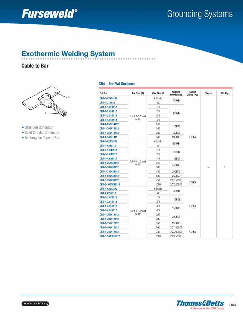
w w w . t n b . c a D69
Grounding Systems
CB4 – For Flat Surfaces
Cat. No. Bar Size (A) Wire Size (B) Welding Powder size
Handle Clamp Type Sleeve Std. Qty.
CB4-4-#2S14112
1/4 X 1-1/2 and wider
#2 solid45BKB
HCPK4
– 1
CB4-4-214112 #2
CB4-4-1/014112 1/0
90BKBCB4-4-2/014112 2/0
CB4-4-3/014112 3/0
CB4-4-4/014112 4/0
CB4-4-250K14112 250115BKB
CB4-4-300K14112 300
CB4-4-350K14112 350 150BKB
CB4-4-500K1411 500 200BKB
CB4-4-#2S38112
3/8 X 1-1/2 and wider
#2 solid65BKB
CB4-4-#238112 #2
CB4-4-1/038112 1/090BKB
CB4-4-2/038112 2/0
CB4-4-4/038112 4/0 115BKB
CB4-4-250K38112 250150BKB
CB4-4-300K38112 300
CB4-4-350K38112 350 200BKB
CB4-4-500K38112 500 250BKB
CB4-5-750K38112 750 2 X 150BKBHCPK5
CB4-5-1000K38112 1000 2 X 200BKB
CB4-4-#2S12112
1/2 X 1-1/2 and wider
#2 solid90BKB
HCPK4
CB4-4-#212112 #2
CB4-4-1/012112 1/0115BKB
CB4-4-2/012112 2/0
CB4-4-3/012112 3/0150BKB
CB4-4-4/012112 4/0
CB4-4-250K12112 250200BKB
CB4-4-300K12112 300
CB4-4-350K12112 350 250BKB
CB4-5-500K12112 500 2 X 150BKB
HCPK5CB4-5-750K12112 750 2 X 200BKB
CB4-5-1000K12112 1000 2 X 250BKB
A
• Stranded Conductor• Solid Circular Conductor• Rectangular Tape or Bar
B
Exothermic Welding System
Cable to Bar
SectionD-grounding-systems.indd 69 6/6/2017 9:44:02 AM
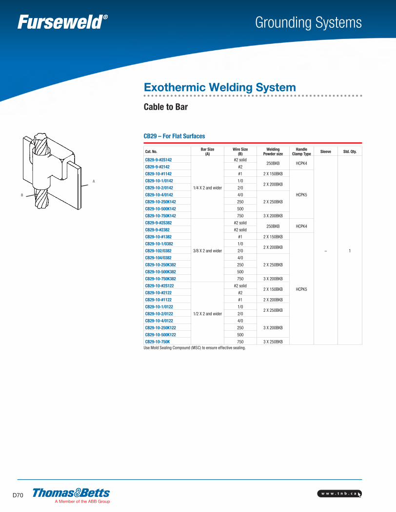
w w w . t n b . c aD70
Grounding Systems
CB29 – For Flat Surfaces
Cat. No. Bar Size(A)
Wire Size(B)
Welding Powder size
Handle Clamp Type Sleeve Std. Qty.
CB29-9-#2S142
1/4 X 2 and wider
#2 solid250BKB HCPK4
– 1
CB29-9-#2142 #2
CB29-10-#1142 #1 2 X 150BKB
HCPK5
CB29-10-1/0142 1/02 X 200BKB
CB29-10-2/0142 2/0
CB29-10-4/0142 4/0
2 X 250BKBCB29-10-250K142 250
CB29-10-500K142 500
CB29-10-750K142 750 3 X 200BKB
CB29-9-#2S382
3/8 X 2 and wider
#2 solid250BKB HCPK4
CB29-9-#2382 #2 solid
CB29-10-#1382 #1 2 X 150BKB
HCPK5
CB29-10-1/0382 1/02 X 200BKB
CB29-102/0382 2/0
CB29-104/0382 4/0
2 X 250BKBCB29-10-250K382 250
CB29-10-500K382 500
CB29-10-750K382 750 3 X 200BKB
CB29-10-#2S122
1/2 X 2 and wider
#2 solid2 X 150BKB
CB29-10-#2122 #2
CB29-10-#1122 #1 2 X 200BKB
CB29-10-1/0122 1/02 X 250BKB
CB29-10-2/0122 2/0
CB29-10-4/0122 4/0
3 X 200BKBCB29-10-250K122 250
CB29-10-500K122 500
CB29-10-750K 750 3 X 250BKBUse Mold Sealing Compound (MSC) to ensure effective sealing.
A
B
Exothermic Welding System
Cable to Bar
SectionD-grounding-systems.indd 70 6/6/2017 9:44:03 AM
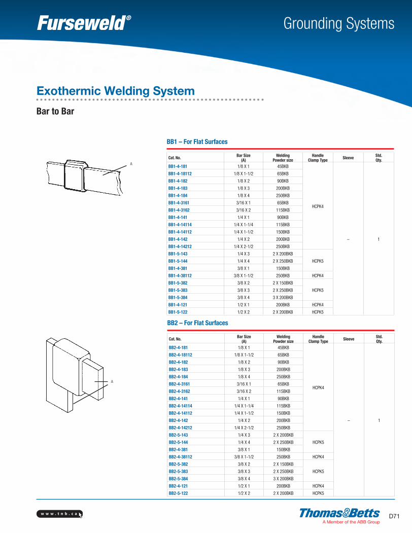
w w w . t n b . c a D71
Grounding Systems
A
A
BB1 – For Flat Surfaces
Cat. No. Bar Size(A)
Welding Powder size
Handle Clamp Type Sleeve Std.
Qty.BB1-4-181 1/8 X 1 45BKB
HCPK4
– 1
BB1-4-18112 1/8 X 1-1/2 65BKB
BB1-4-182 1/8 X 2 90BKB
BB1-4-183 1/8 X 3 200BKB
BB1-4-184 1/8 X 4 250BKB
BB1-4-3161 3/16 X 1 65BKB
BB1-4-3162 3/16 X 2 115BKB
BB1-4-141 1/4 X 1 90BKB
BB1-4-14114 1/4 X 1-1/4 115BKB
BB1-4-14112 1/4 X 1-1/2 150BKB
BB1-4-142 1/4 X 2 200BKB
BB1-4-14212 1/4 X 2-1/2 250BKB
BB1-5-143 1/4 X 3 2 X 200BKB
HCPK5BB1-5-144 1/4 X 4 2 X 250BKB
BB1-4-381 3/8 X 1 150BKB
BB1-4-38112 3/8 X 1-1/2 250BKB HCPK4
BB1-5-382 3/8 X 2 2 X 150BKB
HCPK5BB1-5-383 3/8 X 3 2 X 250BKB
BB1-5-384 3/8 X 4 3 X 200BKB
BB1-4-121 1/2 X 1 200BKB HCPK4
BB1-5-122 1/2 X 2 2 X 200BKB HCPK5
BB2 – For Flat Surfaces
Cat. No. Bar Size(A)
Welding Powder size
Handle Clamp Type Sleeve Std.
Qty.BB2-4-181 1/8 X 1 45BKB
HCPK4
– 1
BB2-4-18112 1/8 X 1-1/2 65BKB
BB2-4-182 1/8 X 2 90BKB
BB2-4-183 1/8 X 3 200BKB
BB2-4-184 1/8 X 4 250BKB
BB2-4-3161 3/16 X 1 65BKB
BB2-4-3162 3/16 X 2 115BKB
BB2-4-141 1/4 X 1 90BKB
BB2-4-14114 1/4 X 1-1/4 115BKB
BB2-4-14112 1/4 X 1-1/2 150BKB
BB2-4-142 1/4 X 2 200BKB
BB2-4-14212 1/4 X 2-1/2 250BKB
BB2-5-143 1/4 X 3 2 X 200BKB
HCPK5BB2-5-144 1/4 X 4 2 X 250BKB
BB2-4-381 3/8 X 1 150BKB
BB2-4-38112 3/8 X 1-1/2 250BKB HCPK4
BB2-5-382 3/8 X 2 2 X 150BKB
HCPK5BB2-5-383 3/8 X 3 2 X 250BKB
BB2-5-384 3/8 X 4 3 X 200BKB
BB2-4-121 1/2 X 1 200BKB HCPK4
BB2-5-122 1/2 X 2 2 X 200BKB HCPK5
Exothermic Welding System
Bar to Bar
SectionD-grounding-systems.indd 71 6/6/2017 9:44:03 AM
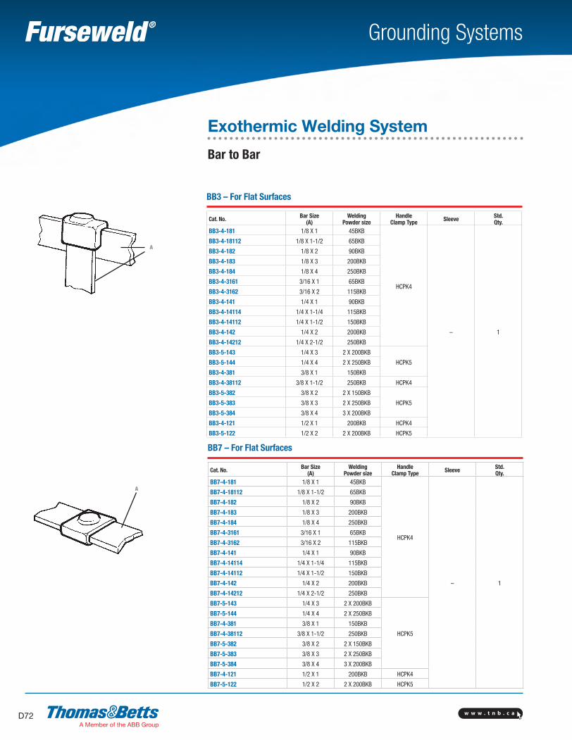
w w w . t n b . c aD72
Grounding Systems
BB3 – For Flat Surfaces
Cat. No. Bar Size(A)
Welding Powder size
Handle Clamp Type Sleeve Std.
Qty.BB3-4-181 1/8 X 1 45BKB
HCPK4
– 1
BB3-4-18112 1/8 X 1-1/2 65BKB
BB3-4-182 1/8 X 2 90BKB
BB3-4-183 1/8 X 3 200BKB
BB3-4-184 1/8 X 4 250BKB
BB3-4-3161 3/16 X 1 65BKB
BB3-4-3162 3/16 X 2 115BKB
BB3-4-141 1/4 X 1 90BKB
BB3-4-14114 1/4 X 1-1/4 115BKB
BB3-4-14112 1/4 X 1-1/2 150BKB
BB3-4-142 1/4 X 2 200BKB
BB3-4-14212 1/4 X 2-1/2 250BKB
BB3-5-143 1/4 X 3 2 X 200BKB
HCPK5BB3-5-144 1/4 X 4 2 X 250BKB
BB3-4-381 3/8 X 1 150BKB
BB3-4-38112 3/8 X 1-1/2 250BKB HCPK4
BB3-5-382 3/8 X 2 2 X 150BKB
HCPK5BB3-5-383 3/8 X 3 2 X 250BKB
BB3-5-384 3/8 X 4 3 X 200BKB
BB3-4-121 1/2 X 1 200BKB HCPK4
BB3-5-122 1/2 X 2 2 X 200BKB HCPK5
BB7 – For Flat Surfaces
Cat. No. Bar Size(A)
Welding Powder size
Handle Clamp Type Sleeve Std.
Qty.BB7-4-181 1/8 X 1 45BKB
HCPK4
– 1
BB7-4-18112 1/8 X 1-1/2 65BKB
BB7-4-182 1/8 X 2 90BKB
BB7-4-183 1/8 X 3 200BKB
BB7-4-184 1/8 X 4 250BKB
BB7-4-3161 3/16 X 1 65BKB
BB7-4-3162 3/16 X 2 115BKB
BB7-4-141 1/4 X 1 90BKB
BB7-4-14114 1/4 X 1-1/4 115BKB
BB7-4-14112 1/4 X 1-1/2 150BKB
BB7-4-142 1/4 X 2 200BKB
BB7-4-14212 1/4 X 2-1/2 250BKB
BB7-5-143 1/4 X 3 2 X 200BKB
HCPK5
BB7-5-144 1/4 X 4 2 X 250BKB
BB7-4-381 3/8 X 1 150BKB
BB7-4-38112 3/8 X 1-1/2 250BKB
BB7-5-382 3/8 X 2 2 X 150BKB
BB7-5-383 3/8 X 3 2 X 250BKB
BB7-5-384 3/8 X 4 3 X 200BKB
BB7-4-121 1/2 X 1 200BKB HCPK4
BB7-5-122 1/2 X 2 2 X 200BKB HCPK5
A
Exothermic Welding System
Bar to Bar
A
SectionD-grounding-systems.indd 72 6/6/2017 9:44:03 AM
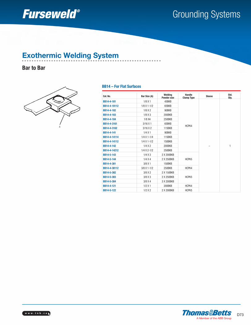
w w w . t n b . c a D73
Grounding Systems
BB14 – For Flat Surfaces
Cat. No. Bar Size (A) Welding Powder size
Handle Clamp Type Sleeve Std.
Qty.BB14-4-181 1/8 X 1 45BKB
HCPK4
– 1
BB14-4-18112 1/8 X 1-1/2 65BKB
BB14-4-182 1/8 X 2 90BKB
BB14-4-183 1/8 X 3 200BKB
BB14-4-184 1/8 X4 250BKB
BB14-4-3161 3/16 X 1 65BKB
BB14-4-3162 3/16 X 2 115BKB
BB14-4-141 1/4 X 1 90BKB
BB14-4-14114 1/4 X 1-1/4 115BKB
BB14-4-14112 1/4 X 1-1/2 150BKB
BB14-4-142 1/4 X 2 200BKB
BB14-4-14212 1/4 X 2-1/2 250BKB
BB14-5-143 1/4 X 3 2 X 200BKB
HCPK5BB14-5-144 1/4 X 4 2 X 250BKB
BB14-4-381 3/8 X 1 150BKB
BB14-4-38112 3/8 X 1-1/2 250BKB HCPK4
BB14-5-382 3/8 X 2 2 X 150BKB
HCPK5BB14-5-383 3/8 X 3 2 X 250BKB
BB14-5-384 3/8 X 4 3 X 200BKB
BB14-4-121 1/2 X 1 200BKB HCPK4
BB14-5-122 1/2 X 2 2 X 200BKB HCPK5
Exothermic Welding System
Bar to Bar
A
SectionD-grounding-systems.indd 73 6/6/2017 9:44:04 AM
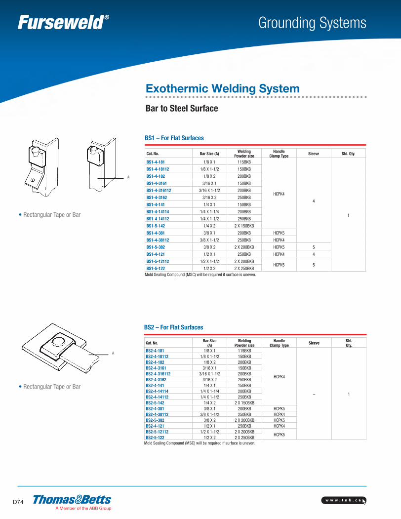
w w w . t n b . c aD74
Grounding Systems
BS1 – For Flat Surfaces
Cat. No. Bar Size (A) Welding Powder size
Handle Clamp Type Sleeve Std. Qty.
BS1-4-181 1/8 X 1 115BKB
HCPK4
4
1
BS1-4-18112 1/8 X 1-1/2 150BKB
BS1-4-182 1/8 X 2 200BKB
BS1-4-3161 3/16 X 1 150BKB
BS1-4-316112 3/16 X 1-1/2 200BKB
BS1-4-3162 3/16 X 2 250BKB
BS1-4-141 1/4 X 1 150BKB
BS1-4-14114 1/4 X 1-1/4 200BKB
BS1-4-14112 1/4 X 1-1/2 250BKB
BS1-5-142 1/4 X 2 2 X 150BKB
BS1-4-381 3/8 X 1 200BKB HCPK5
BS1-4-38112 3/8 X 1-1/2 250BKB HCPK4
BS1-5-382 3/8 X 2 2 X 200BKB HCPK5 5
BS1-4-121 1/2 X 1 250BKB HCPK4 4
BS1-5-12112 1/2 X 1-1/2 2 X 200BKBHCPK5 5
BS1-5-122 1/2 X 2 2 X 250BKBMold Sealing Compound (MSC) will be required if surface is uneven.
BS2 – For Flat Surfaces
Cat. No. Bar Size(A)
Welding Powder size
Handle Clamp Type Sleeve Std.
Qty.BS2-4-181 1/8 X 1 115BKB
HCPK4
– 1
BS2-4-18112 1/8 X 1-1/2 150BKBBS2-4-182 1/8 X 2 200BKBBS2-4-3161 3/16 X 1 150BKBBS2-4-316112 3/16 X 1-1/2 200BKBBS2-4-3162 3/16 X 2 250BKBBS2-4-141 1/4 X 1 150BKBBS2-4-14114 1/4 X 1-1/4 200BKBBS2-4-14112 1/4 X 1-1/2 250BKBBS2-5-142 1/4 X 2 2 X 150BKBBS2-4-381 3/8 X 1 200BKB HCPK5BS2-4-38112 3/8 X 1-1/2 250BKB HCPK4BS2-5-382 3/8 X 2 2 X 200BKB HCPK5BS2-4-121 1/2 X 1 250BKB HCPK4BS2-5-12112 1/2 X 1-1/2 2 X 200BKB
HCPK5BS2-5-122 1/2 X 2 2 X 250BKB
Mold Sealing Compound (MSC) will be required if surface is uneven.
A
• Rectangular Tape or Bar
A
• Rectangular Tape or Bar
Exothermic Welding System
Bar to Steel Surface
SectionD-grounding-systems.indd 74 6/6/2017 9:44:04 AM
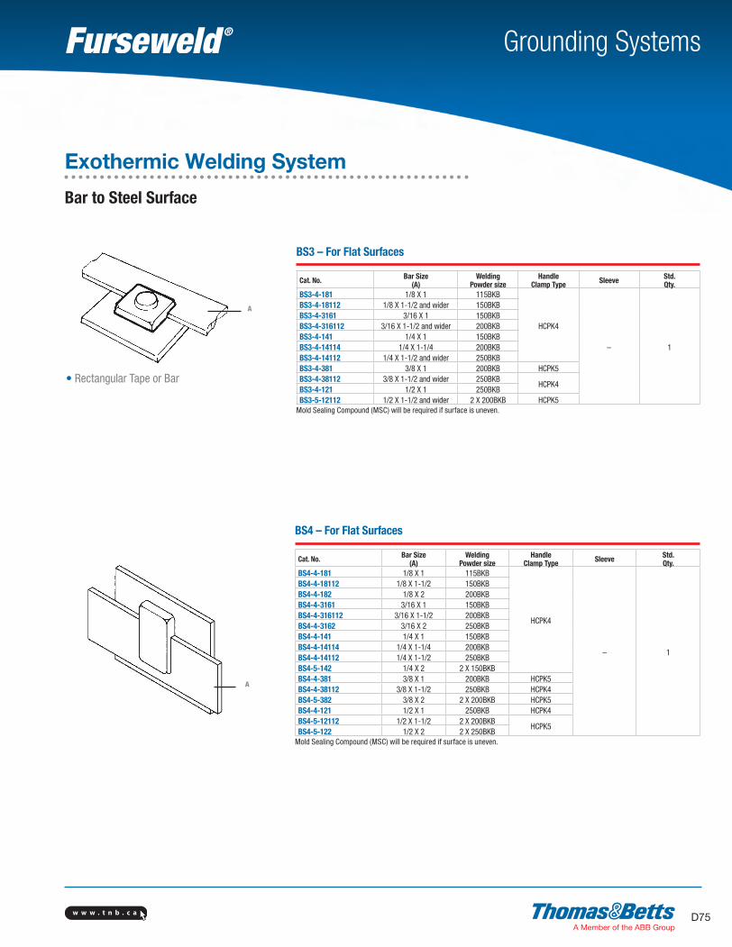
w w w . t n b . c a D75
Grounding Systems
BS3 – For Flat Surfaces
Cat. No. Bar Size(A)
Welding Powder size
Handle Clamp Type Sleeve Std.
Qty.BS3-4-181 1/8 X 1 115BKB
HCPK4
– 1
BS3-4-18112 1/8 X 1-1/2 and wider 150BKBBS3-4-3161 3/16 X 1 150BKBBS3-4-316112 3/16 X 1-1/2 and wider 200BKBBS3-4-141 1/4 X 1 150BKBBS3-4-14114 1/4 X 1-1/4 200BKBBS3-4-14112 1/4 X 1-1/2 and wider 250BKBBS3-4-381 3/8 X 1 200BKB HCPK5BS3-4-38112 3/8 X 1-1/2 and wider 250BKB
HCPK4BS3-4-121 1/2 X 1 250BKBBS3-5-12112 1/2 X 1-1/2 and wider 2 X 200BKB HCPK5
Mold Sealing Compound (MSC) will be required if surface is uneven.
BS4 – For Flat Surfaces
Cat. No. Bar Size(A)
Welding Powder size
Handle Clamp Type Sleeve Std.
Qty.BS4-4-181 1/8 X 1 115BKB
HCPK4
– 1
BS4-4-18112 1/8 X 1-1/2 150BKBBS4-4-182 1/8 X 2 200BKBBS4-4-3161 3/16 X 1 150BKBBS4-4-316112 3/16 X 1-1/2 200BKBBS4-4-3162 3/16 X 2 250BKBBS4-4-141 1/4 X 1 150BKBBS4-4-14114 1/4 X 1-1/4 200BKBBS4-4-14112 1/4 X 1-1/2 250BKBBS4-5-142 1/4 X 2 2 X 150BKBBS4-4-381 3/8 X 1 200BKB HCPK5BS4-4-38112 3/8 X 1-1/2 250BKB HCPK4BS4-5-382 3/8 X 2 2 X 200BKB HCPK5BS4-4-121 1/2 X 1 250BKB HCPK4BS4-5-12112 1/2 X 1-1/2 2 X 200BKB
HCPK5BS4-5-122 1/2 X 2 2 X 250BKB
Mold Sealing Compound (MSC) will be required if surface is uneven.
A
A
• Rectangular Tape or Bar
Exothermic Welding System
Bar to Steel Surface
SectionD-grounding-systems.indd 75 6/6/2017 9:44:05 AM
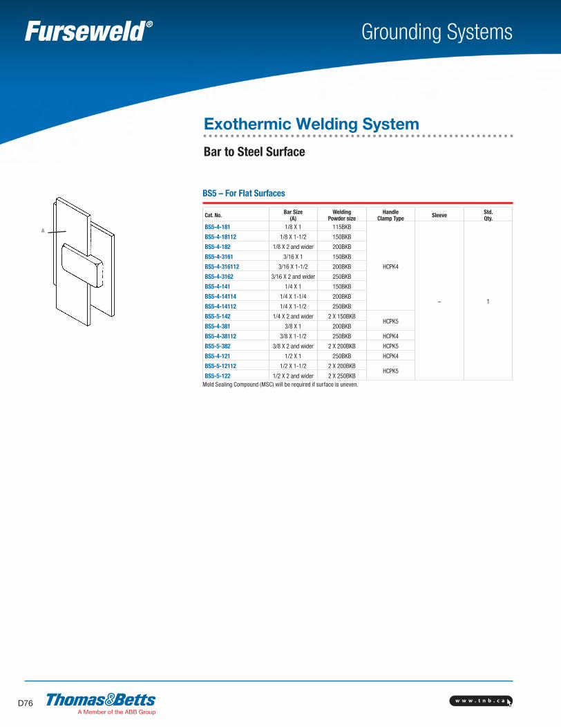
w w w . t n b . c aD76
Grounding Systems
BS5 – For Flat Surfaces
Cat. No. Bar Size(A)
Welding Powder size
Handle Clamp Type Sleeve Std.
Qty.BS5-4-181 1/8 X 1 115BKB
HCPK4
– 1
BS5-4-18112 1/8 X 1-1/2 150BKB
BS5-4-182 1/8 X 2 and wider 200BKB
BS5-4-3161 3/16 X 1 150BKB
BS5-4-316112 3/16 X 1-1/2 200BKB
BS5-4-3162 3/16 X 2 and wider 250BKB
BS5-4-141 1/4 X 1 150BKB
BS5-4-14114 1/4 X 1-1/4 200BKB
BS5-4-14112 1/4 X 1-1/2 250BKB
BS5-5-142 1/4 X 2 and wider 2 X 150BKBHCPK5
BS5-4-381 3/8 X 1 200BKB
BS5-4-38112 3/8 X 1-1/2 250BKB HCPK4
BS5-5-382 3/8 X 2 and wider 2 X 200BKB HCPK5
BS5-4-121 1/2 X 1 250BKB HCPK4
BS5-5-12112 1/2 X 1-1/2 2 X 200BKBHCPK5
BS5-5-122 1/2 X 2 and wider 2 X 250BKBMold Sealing Compound (MSC) will be required if surface is uneven.
A
Exothermic Welding System
Bar to Steel Surface
SectionD-grounding-systems.indd 76 6/6/2017 9:44:05 AM

w w w . t n b . c a D77
Grounding Systems
BCMSTM1-TB
Handle Clamps
Cat. No. Description Applications Std. Qty.
HCPK1 Price Key 1 Handle For use on price key 1 molds
1
HCPK2 Price Key 2 Handle For use on price key 2 molds
HCPK3 Price Key 3 Handle Clamp For use on price key 3 molds
HCPK3A Price Key 3A Handle Clamp Type 3A molds (connections to vertical rebars)
HCPK3B Price Key 3B Handle Clamp Type 3B molds (connections to horizontal rebars)
HCPK3BMOD Price Key 3B Modified Clamp Type 3B molds (cross connections to horizontal rebars)
HCPK4 Price Key 4 Handle Clamp For use on price key 4 molds
HCPK5 Price Key 5 Handle Clamp For use on price key 5 molds
HCPK7 Price Key 7 Handle Clamp For use on price key 7 molds
HCPK8 Price Key 8 Handle Clamp For use on price key 8 molds
FRAME1 Price Key 9 Frame For use with HCPK4 on price key 9 molds
FRAME2 Price Key 10 Frame For use with HCPK5 on price key 10 molds
FGUN
BFC
HCPK2
HCPK3
FRAME 1HCPK4
Tools and Accessories
Cat. No. Description Applications Std. Qty.
WWB1 Cable Cleaning Brush Cleaning of stranded and other circular section conductors 6
WRB1 Replacement Elements (Pair) – 3
BFC Card Cloth Brush Cleaning of conductors and surfaces
10FGUN Flint Ignitor Gun Starting powder ignition
BCM Mold Cleaning Brush Soft brush for mold cleaning
STM1-TB Mold Scraper Tool Break up and removal of slag in mold crucible
MSC Mold Sealing Compound Mold sealing on uneven surfaces, and general mold sealing 5
PACK-A Packing Mold sealing on rebar surfaces 50
SLEEVE#6 Sleeve for #6 wire
Prevents burning of small section wire100
SLEEVE#6S Sleeve for #6S wire
SLEEVE#8 Sleeve for #8 wire
SLEEVE#8S Sleeve for #8S wire
SHIM Copper shim. For sealing around undersize conductors
Exothermic Welding System
Handle Clamps, Tools and Accessories
SectionD-grounding-systems.indd 77 6/6/2017 9:44:07 AM

w w w . t n b . c aD78
Grounding Systems
Cover
.549 in.3.450 in.
1.794 in.
Welding Mold Disk
Exothermic Welding System
Sure Shot™ Welding MoldThomas & Betts introduces a new approach to the perfect connection Sure Shot™ an extension of the Furseweld® line of exothermic welding products.
Sure Shot™ molds come completely packaged with everything necessary for a connection. They are fast and easy to use. The contractor simply positions the mold, adds the weld powder and starting powder, and ignites it with a flint gun.
Sure Shot™ molds are disposable, so there’s no maintenance involved. And, it’s not necessary to remove the mold in underground installations because Sure Shot™ molds are made from an “earth friendly” ceramic.
The hexagonal Sure Shot™ design is easy to grasp and hold without removing safety gloves, and it won’t roll away if it’s laid down while the installer prepares the connection.
Features and Benefits:• Fast and easy to use• Packaged with everything necessary for a connection• Maintenance-free disposable molds• Made of biodegradable ceramic• Ergonomic hexagonal design
1.714 in.
SectionD-grounding-systems.indd 78 6/6/2017 9:44:08 AM
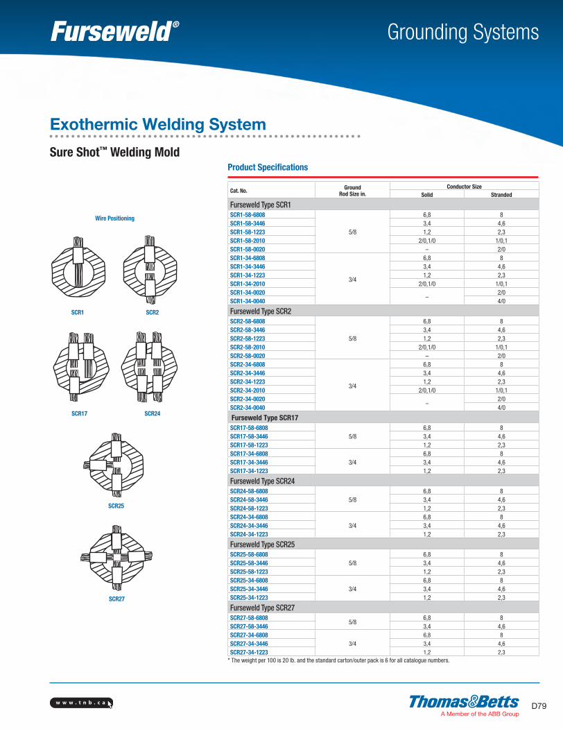
w w w . t n b . c a D79
Grounding Systems
Product Specifications
Cat. No. GroundRod Size in.
Conductor SizeSolid Stranded
Furseweld Type SCR1SCR1-58-6808
5/8
6,8 8SCR1-58-3446 3,4 4,6SCR1-58-1223 1,2 2,3SCR1-58-2010 2/0,1/0 1/0,1SCR1-58-0020 – 2/0SCR1-34-6808
3/4
6,8 8SCR1-34-3446 3,4 4,6SCR1-34-1223 1,2 2,3SCR1-34-2010 2/0,1/0 1/0,1SCR1-34-0020
–2/0
SCR1-34-0040 4/0
Furseweld Type SCR2SCR2-58-6808
5/8
6,8 8SCR2-58-3446 3,4 4,6SCR2-58-1223 1,2 2,3SCR2-58-2010 2/0,1/0 1/0,1SCR2-58-0020 – 2/0SCR2-34-6808
3/4
6,8 8SCR2-34-3446 3,4 4,6SCR2-34-1223 1,2 2,3SCR2-34-2010 2/0,1/0 1/0,1SCR2-34-0020
–2/0
SCR2-34-0040 4/0
Furseweld Type SCR17SCR17-58-6808
5/86,8 8
SCR17-58-3446 3,4 4,6SCR17-58-1223 1,2 2,3SCR17-34-6808
3/46,8 8
SCR17-34-3446 3,4 4,6SCR17-34-1223 1,2 2,3
Furseweld Type SCR24SCR24-58-6808
5/86,8 8
SCR24-58-3446 3,4 4,6SCR24-58-1223 1,2 2,3SCR24-34-6808
3/46,8 8
SCR24-34-3446 3,4 4,6SCR24-34-1223 1,2 2,3
Furseweld Type SCR25SCR25-58-6808
5/86,8 8
SCR25-58-3446 3,4 4,6SCR25-58-1223 1,2 2,3SCR25-34-6808
3/46,8 8
SCR25-34-3446 3,4 4,6SCR25-34-1223 1,2 2,3
Furseweld Type SCR27SCR27-58-6808
5/86,8 8
SCR27-58-3446 3,4 4,6SCR27-34-6808
3/4
6,8 8
SCR27-34-3446 3,4 4,6
SCR27-34-1223 1,2 2,3* The weight per 100 is 20 lb. and the standard carton/outer pack is 6 for all catalogue numbers.
Wire Positioning
SCR1 SCR2
SCR17 SCR24
SCR25
SCR27
Exothermic Welding System
Sure Shot™ Welding Mold
SectionD-grounding-systems.indd 79 6/6/2017 9:44:09 AM
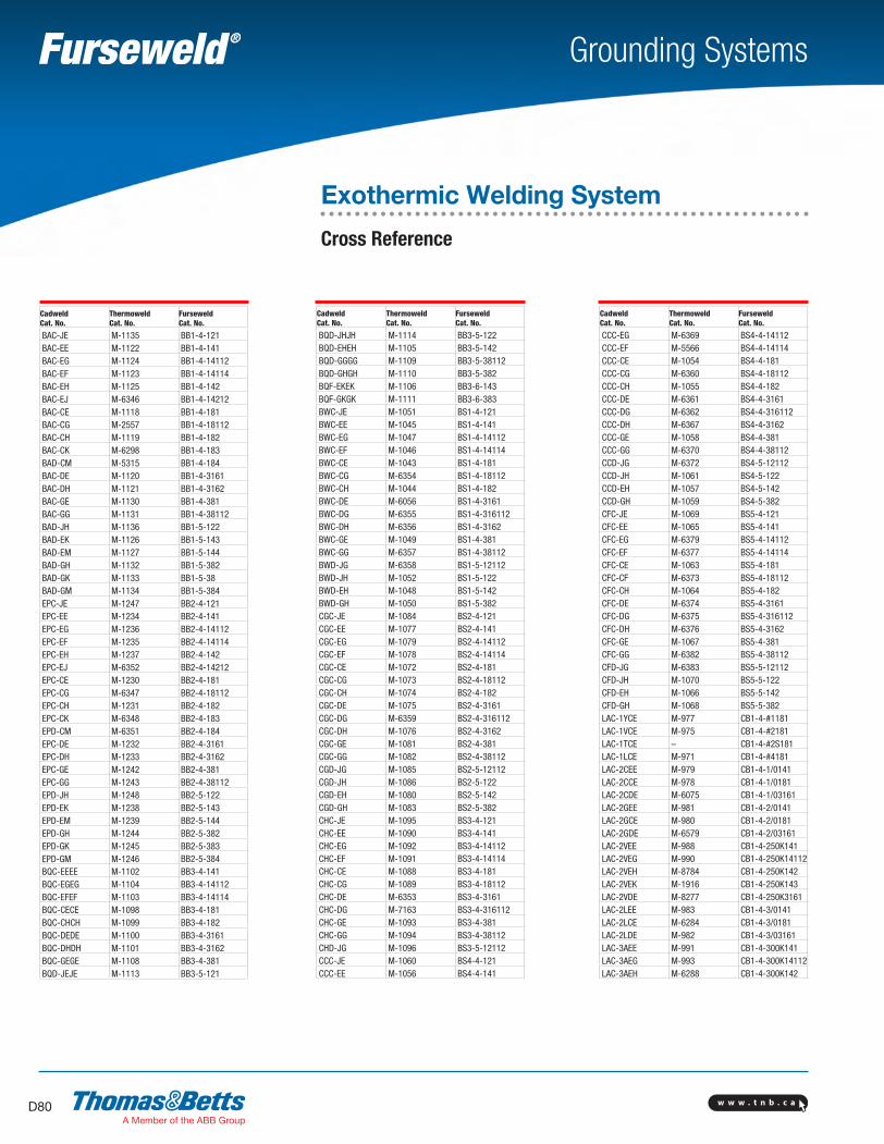
w w w . t n b . c aD80
Grounding Systems
Cadweld Cat. No.
Thermoweld Cat. No.
Furseweld Cat. No.
BAC-JE M-1135 BB1-4-121BAC-EE M-1122 BB1-4-141BAC-EG M-1124 BB1-4-14112BAC-EF M-1123 BB1-4-14114BAC-EH M-1125 BB1-4-142BAC-EJ M-6346 BB1-4-14212BAC-CE M-1118 BB1-4-181BAC-CG M-2557 BB1-4-18112BAC-CH M-1119 BB1-4-182BAC-CK M-6298 BB1-4-183BAD-CM M-5315 BB1-4-184BAC-DE M-1120 BB1-4-3161BAC-DH M-1121 BB1-4-3162BAC-GE M-1130 BB1-4-381BAC-GG M-1131 BB1-4-38112BAD-JH M-1136 BB1-5-122BAD-EK M-1126 BB1-5-143BAD-EM M-1127 BB1-5-144BAD-GH M-1132 BB1-5-382BAD-GK M-1133 BB1-5-38BAD-GM M-1134 BB1-5-384EPC-JE M-1247 BB2-4-121EPC-EE M-1234 BB2-4-141EPC-EG M-1236 BB2-4-14112EPC-EF M-1235 BB2-4-14114EPC-EH M-1237 BB2-4-142EPC-EJ M-6352 BB2-4-14212EPC-CE M-1230 BB2-4-181EPC-CG M-6347 BB2-4-18112EPC-CH M-1231 BB2-4-182EPC-CK M-6348 BB2-4-183EPD-CM M-6351 BB2-4-184EPC-DE M-1232 BB2-4-3161EPC-DH M-1233 BB2-4-3162EPC-GE M-1242 BB2-4-381EPC-GG M-1243 BB2-4-38112EPD-JH M-1248 BB2-5-122EPD-EK M-1238 BB2-5-143EPD-EM M-1239 BB2-5-144EPD-GH M-1244 BB2-5-382EPD-GK M-1245 BB2-5-383EPD-GM M-1246 BB2-5-384BQC-EEEE M-1102 BB3-4-141BQC-EGEG M-1104 BB3-4-14112BQC-EFEF M-1103 BB3-4-14114BQC-CECE M-1098 BB3-4-181BQC-CHCH M-1099 BB3-4-182BQC-DEDE M-1100 BB3-4-3161BQC-DHDH M-1101 BB3-4-3162BQC-GEGE M-1108 BB3-4-381BQD-JEJE M-1113 BB3-5-121
Cadweld Cat. No.
Thermoweld Cat. No.
Furseweld Cat. No.
BQD-JHJH M-1114 BB3-5-122BQD-EHEH M-1105 BB3-5-142BQD-GGGG M-1109 BB3-5-38112BQD-GHGH M-1110 BB3-5-382BQF-EKEK M-1106 BB3-6-143BQF-GKGK M-1111 BB3-6-383BWC-JE M-1051 BS1-4-121BWC-EE M-1045 BS1-4-141BWC-EG M-1047 BS1-4-14112BWC-EF M-1046 BS1-4-14114BWC-CE M-1043 BS1-4-181BWC-CG M-6354 BS1-4-18112BWC-CH M-1044 BS1-4-182BWC-DE M-6056 BS1-4-3161BWC-DG M-6355 BS1-4-316112BWC-DH M-6356 BS1-4-3162BWC-GE M-1049 BS1-4-381BWC-GG M-6357 BS1-4-38112BWD-JG M-6358 BS1-5-12112BWD-JH M-1052 BS1-5-122BWD-EH M-1048 BS1-5-142BWD-GH M-1050 BS1-5-382CGC-JE M-1084 BS2-4-121CGC-EE M-1077 BS2-4-141CGC-EG M-1079 BS2-4-14112CGC-EF M-1078 BS2-4-14114CGC-CE M-1072 BS2-4-181CGC-CG M-1073 BS2-4-18112CGC-CH M-1074 BS2-4-182CGC-DE M-1075 BS2-4-3161CGC-DG M-6359 BS2-4-316112CGC-DH M-1076 BS2-4-3162CGC-GE M-1081 BS2-4-381CGC-GG M-1082 BS2-4-38112CGD-JG M-1085 BS2-5-12112CGD-JH M-1086 BS2-5-122CGD-EH M-1080 BS2-5-142CGD-GH M-1083 BS2-5-382CHC-JE M-1095 BS3-4-121CHC-EE M-1090 BS3-4-141CHC-EG M-1092 BS3-4-14112CHC-EF M-1091 BS3-4-14114CHC-CE M-1088 BS3-4-181CHC-CG M-1089 BS3-4-18112CHC-DE M-6353 BS3-4-3161CHC-DG M-7163 BS3-4-316112CHC-GE M-1093 BS3-4-381CHC-GG M-1094 BS3-4-38112CHD-JG M-1096 BS3-5-12112CCC-JE M-1060 BS4-4-121CCC-EE M-1056 BS4-4-141
Cadweld Cat. No.
Thermoweld Cat. No.
Furseweld Cat. No.
CCC-EG M-6369 BS4-4-14112CCC-EF M-5566 BS4-4-14114CCC-CE M-1054 BS4-4-181CCC-CG M-6360 BS4-4-18112CCC-CH M-1055 BS4-4-182CCC-DE M-6361 BS4-4-3161CCC-DG M-6362 BS4-4-316112CCC-DH M-6367 BS4-4-3162CCC-GE M-1058 BS4-4-381CCC-GG M-6370 BS4-4-38112CCD-JG M-6372 BS4-5-12112CCD-JH M-1061 BS4-5-122CCD-EH M-1057 BS4-5-142CCD-GH M-1059 BS4-5-382CFC-JE M-1069 BS5-4-121CFC-EE M-1065 BS5-4-141CFC-EG M-6379 BS5-4-14112CFC-EF M-6377 BS5-4-14114CFC-CE M-1063 BS5-4-181CFC-CF M-6373 BS5-4-18112CFC-CH M-1064 BS5-4-182CFC-DE M-6374 BS5-4-3161CFC-DG M-6375 BS5-4-316112CFC-DH M-6376 BS5-4-3162CFC-GE M-1067 BS5-4-381CFC-GG M-6382 BS5-4-38112CFD-JG M-6383 BS5-5-12112CFD-JH M-1070 BS5-5-122CFD-EH M-1066 BS5-5-142CFD-GH M-1068 BS5-5-382LAC-1YCE M-977 CB1-4-#1181LAC-1VCE M-975 CB1-4-#2181LAC-1TCE – CB1-4-#2S181LAC-1LCE M-971 CB1-4-#4181LAC-2CEE M-979 CB1-4-1/0141LAC-2CCE M-978 CB1-4-1/0181LAC-2CDE M-6075 CB1-4-1/03161LAC-2GEE M-981 CB1-4-2/0141LAC-2GCE M-980 CB1-4-2/0181LAC-2GDE M-6579 CB1-4-2/03161LAC-2VEE M-988 CB1-4-250K141LAC-2VEG M-990 CB1-4-250K14112LAC-2VEH M-8784 CB1-4-250K142LAC-2VEK M-1916 CB1-4-250K143LAC-2VDE M-8277 CB1-4-250K3161LAC-2LEE M-983 CB1-4-3/0141LAC-2LCE M-6284 CB1-4-3/0181LAC-2LDE M-982 CB1-4-3/03161LAC-3AEE M-991 CB1-4-300K141LAC-3AEG M-993 CB1-4-300K14112LAC-3AEH M-6288 CB1-4-300K142
Exothermic Welding System
Cross Reference
SectionD-grounding-systems.indd 80 6/6/2017 9:44:09 AM
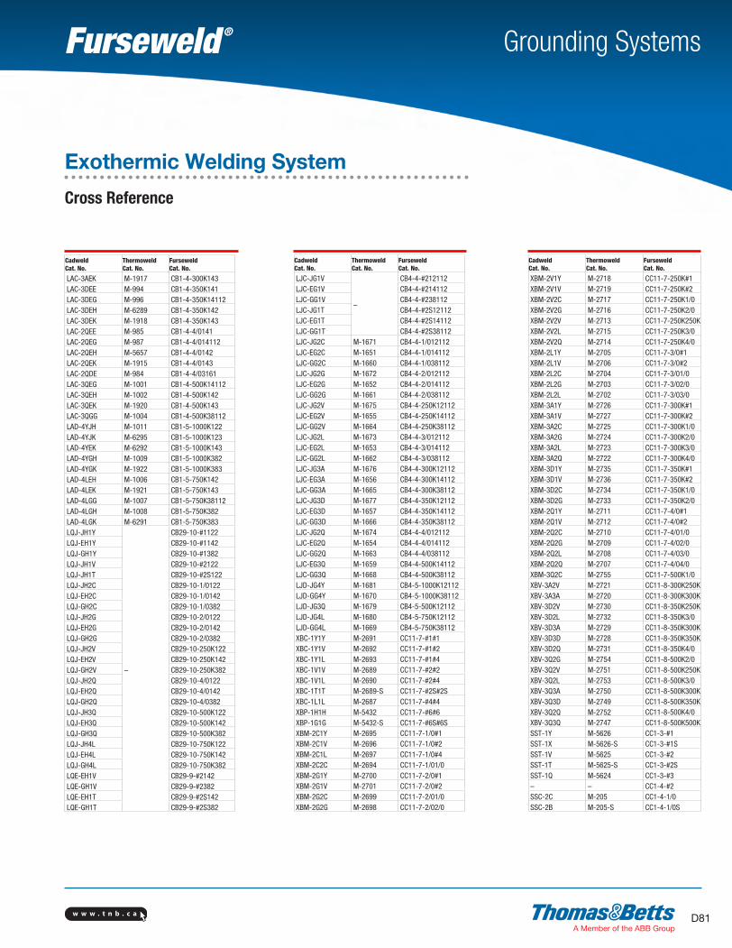
w w w . t n b . c a D81
Grounding Systems
Cadweld Cat. No.
Thermoweld Cat. No.
Furseweld Cat. No.
LAC-3AEK M-1917 CB1-4-300K143LAC-3DEE M-994 CB1-4-350K141LAC-3DEG M-996 CB1-4-350K14112LAC-3DEH M-6289 CB1-4-350K142LAC-3DEK M-1918 CB1-4-350K143LAC-2QEE M-985 CB1-4-4/0141LAC-2QEG M-987 CB1-4-4/014112LAC-2QEH M-5657 CB1-4-4/0142LAC-2QEK M-1915 CB1-4-4/0143LAC-2QDE M-984 CB1-4-4/03161LAC-3QEG M-1001 CB1-4-500K14112LAC-3QEH M-1002 CB1-4-500K142LAC-3QEK M-1920 CB1-4-500K143LAC-3QGG M-1004 CB1-4-500K38112LAD-4YJH M-1011 CB1-5-1000K122LAD-4YJK M-6295 CB1-5-1000K123LAD-4YEK M-6292 CB1-5-1000K143LAD-4YGH M-1009 CB1-5-1000K382LAD-4YGK M-1922 CB1-5-1000K383LAD-4LEH M-1006 CB1-5-750K142LAD-4LEK M-1921 CB1-5-750K143LAD-4LGG M-1007 CB1-5-750K38112LAD-4LGH M-1008 CB1-5-750K382LAD-4LGK M-6291 CB1-5-750K383LQJ-JH1Y
–
CB29-10-#1122LQJ-EH1Y CB29-10-#1142LQJ-GH1Y CB29-10-#1382LQJ-JH1V CB29-10-#2122LQJ-JH1T CB29-10-#2S122LQJ-JH2C CB29-10-1/0122LQJ-EH2C CB29-10-1/0142LQJ-GH2C CB29-10-1/0382LQJ-JH2G CB29-10-2/0122LQJ-EH2G CB29-10-2/0142LQJ-GH2G CB29-10-2/0382LQJ-JH2V CB29-10-250K122LQJ-EH2V CB29-10-250K142LQJ-GH2V CB29-10-250K382LQJ-JH2Q CB29-10-4/0122LQJ-EH2Q CB29-10-4/0142LQJ-GH2Q CB29-10-4/0382LQJ-JH3Q CB29-10-500K122LQJ-EH3Q CB29-10-500K142LQJ-GH3Q CB29-10-500K382LQJ-JH4L CB29-10-750K122LQJ-EH4L CB29-10-750K142LQJ-GH4L CB29-10-750K382LQE-EH1V CB29-9-#2142LQE-GH1V CB29-9-#2382LQE-EH1T CB29-9-#2S142LQE-GH1T CB29-9-#2S382
Cadweld Cat. No.
Thermoweld Cat. No.
Furseweld Cat. No.
LJC-JG1V
–
CB4-4-#212112LJC-EG1V CB4-4-#214112LJC-GG1V CB4-4-#238112LJC-JG1T CB4-4-#2S12112LJC-EG1T CB4-4-#2S14112LJC-GG1T CB4-4-#2S38112LJC-JG2C M-1671 CB4-4-1/012112LJC-EG2C M-1651 CB4-4-1/014112LJC-GG2C M-1660 CB4-4-1/038112LJC-JG2G M-1672 CB4-4-2/012112LJC-EG2G M-1652 CB4-4-2/014112LJC-GG2G M-1661 CB4-4-2/038112LJC-JG2V M-1675 CB4-4-250K12112LJC-EG2V M-1655 CB4-4-250K14112LJC-GG2V M-1664 CB4-4-250K38112LJC-JG2L M-1673 CB4-4-3/012112LJC-EG2L M-1653 CB4-4-3/014112LJC-GG2L M-1662 CB4-4-3/038112LJC-JG3A M-1676 CB4-4-300K12112LJC-EG3A M-1656 CB4-4-300K14112LJC-GG3A M-1665 CB4-4-300K38112LJC-JG3D M-1677 CB4-4-350K12112LJC-EG3D M-1657 CB4-4-350K14112LJC-GG3D M-1666 CB4-4-350K38112LJC-JG2Q M-1674 CB4-4-4/012112LJC-EG2Q M-1654 CB4-4-4/014112LJC-GG2Q M-1663 CB4-4-4/038112LJC-EG3Q M-1659 CB4-4-500K14112LJC-GG3Q M-1668 CB4-4-500K38112LJD-JG4Y M-1681 CB4-5-1000K12112LJD-GG4Y M-1670 CB4-5-1000K38112LJD-JG3Q M-1679 CB4-5-500K12112LJD-JG4L M-1680 CB4-5-750K12112LJD-GG4L M-1669 CB4-5-750K38112XBC-1Y1Y M-2691 CC11-7-#1#1XBC-1Y1V M-2692 CC11-7-#1#2XBC-1Y1L M-2693 CC11-7-#1#4XBC-1V1V M-2689 CC11-7-#2#2XBC-1V1L M-2690 CC11-7-#2#4XBC-1T1T M-2689-S CC11-7-#2S#2SXBC-1L1L M-2687 CC11-7-#4#4XBP-1H1H M-5432 CC11-7-#6#6XBP-1G1G M-5432-S CC11-7-#6S#6SXBM-2C1Y M-2695 CC11-7-1/0#1XBM-2C1V M-2696 CC11-7-1/0#2XBM-2C1L M-2697 CC11-7-1/0#4XBM-2C2C M-2694 CC11-7-1/01/0XBM-2G1Y M-2700 CC11-7-2/0#1XBM-2G1V M-2701 CC11-7-2/0#2XBM-2G2C M-2699 CC11-7-2/01/0XBM-2G2G M-2698 CC11-7-2/02/0
Cadweld Cat. No.
Thermoweld Cat. No.
Furseweld Cat. No.
XBM-2V1Y M-2718 CC11-7-250K#1XBM-2V1V M-2719 CC11-7-250K#2XBM-2V2C M-2717 CC11-7-250K1/0XBM-2V2G M-2716 CC11-7-250K2/0XBM-2V2V M-2713 CC11-7-250K250KXBM-2V2L M-2715 CC11-7-250K3/0XBM-2V2Q M-2714 CC11-7-250K4/0XBM-2L1Y M-2705 CC11-7-3/0#1XBM-2L1V M-2706 CC11-7-3/0#2XBM-2L2C M-2704 CC11-7-3/01/0XBM-2L2G M-2703 CC11-7-3/02/0XBM-2L2L M-2702 CC11-7-3/03/0XBM-3A1Y M-2726 CC11-7-300K#1XBM-3A1V M-2727 CC11-7-300K#2XBM-3A2C M-2725 CC11-7-300K1/0XBM-3A2G M-2724 CC11-7-300K2/0XBM-3A2L M-2723 CC11-7-300K3/0XBM-3A2Q M-2722 CC11-7-300K4/0XBM-3D1Y M-2735 CC11-7-350K#1XBM-3D1V M-2736 CC11-7-350K#2XBM-3D2C M-2734 CC11-7-350K1/0XBM-3D2G M-2733 CC11-7-350K2/0XBM-2Q1Y M-2711 CC11-7-4/0#1XBM-2Q1V M-2712 CC11-7-4/0#2XBM-2Q2C M-2710 CC11-7-4/01/0XBM-2Q2G M-2709 CC11-7-4/02/0XBM-2Q2L M-2708 CC11-7-4/03/0XBM-2Q2Q M-2707 CC11-7-4/04/0XBM-3Q2C M-2755 CC11-7-500K1/0XBV-3A2V M-2721 CC11-8-300K250KXBV-3A3A M-2720 CC11-8-300K300KXBV-3D2V M-2730 CC11-8-350K250KXBV-3D2L M-2732 CC11-8-350K3/0XBV-3D3A M-2729 CC11-8-350K300KXBV-3D3D M-2728 CC11-8-350K350KXBV-3D2Q M-2731 CC11-8-350K4/0XBV-3Q2G M-2754 CC11-8-500K2/0XBV-3Q2V M-2751 CC11-8-500K250KXBV-3Q2L M-2753 CC11-8-500K3/0XBV-3Q3A M-2750 CC11-8-500K300KXBV-3Q3D M-2749 CC11-8-500K350KXBV-3Q2Q M-2752 CC11-8-500K4/0XBV-3Q3Q M-2747 CC11-8-500K500KSST-1Y M-5626 CC1-3-#1SST-1X M-5626-S CC1-3-#1SSST-1V M-5625 CC1-3-#2SST-1T M-5625-S CC1-3-#2SSST-1Q M-5624 CC1-3-#3– – CC1-4-#2SSC-2C M-205 CC1-4-1/0SSC-2B M-205-S CC1-4-1/0S
Exothermic Welding System
Cross Reference
SectionD-grounding-systems.indd 81 6/6/2017 9:44:10 AM
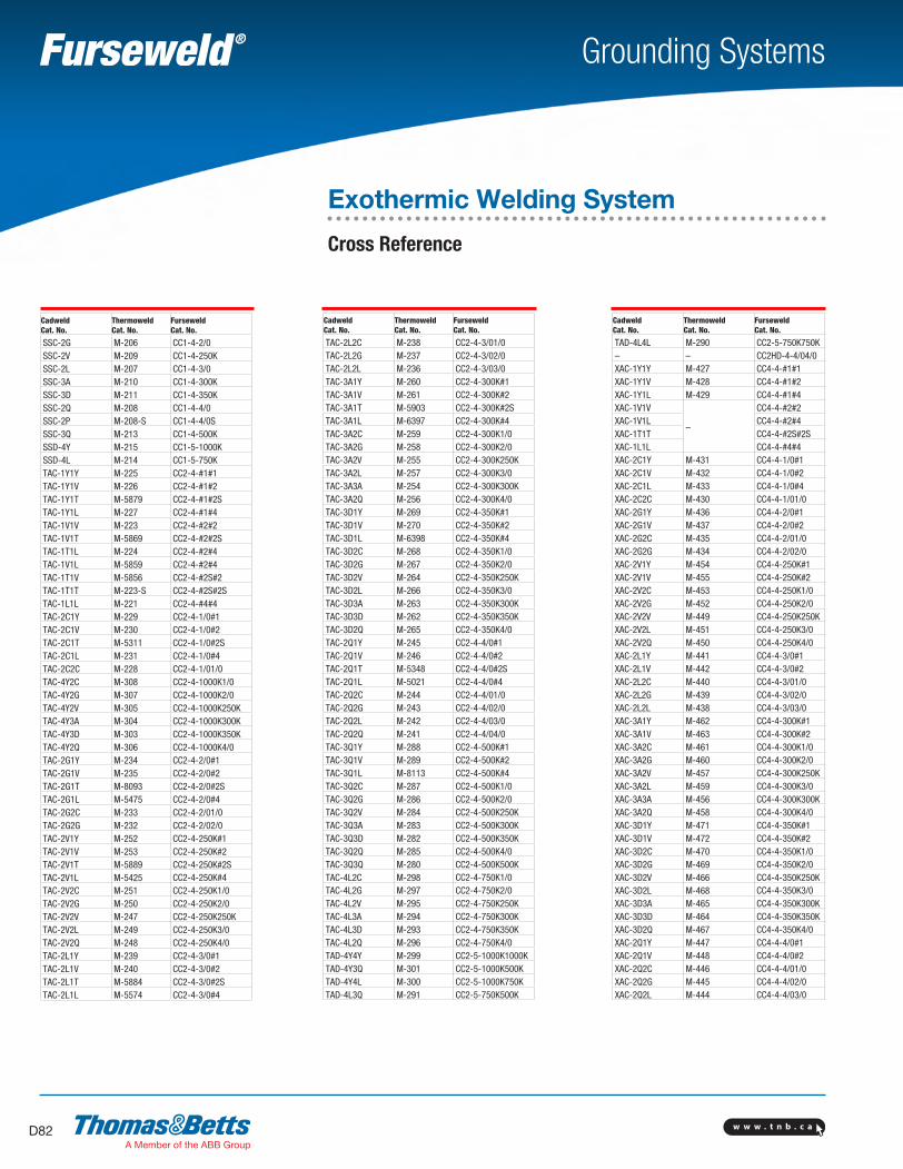
w w w . t n b . c aD82
Grounding Systems
Cadweld Cat. No.
Thermoweld Cat. No.
Furseweld Cat. No.
SSC-2G M-206 CC1-4-2/0SSC-2V M-209 CC1-4-250KSSC-2L M-207 CC1-4-3/0SSC-3A M-210 CC1-4-300KSSC-3D M-211 CC1-4-350KSSC-2Q M-208 CC1-4-4/0SSC-2P M-208-S CC1-4-4/0SSSC-3Q M-213 CC1-4-500KSSD-4Y M-215 CC1-5-1000KSSD-4L M-214 CC1-5-750KTAC-1Y1Y M-225 CC2-4-#1#1TAC-1Y1V M-226 CC2-4-#1#2TAC-1Y1T M-5879 CC2-4-#1#2STAC-1Y1L M-227 CC2-4-#1#4TAC-1V1V M-223 CC2-4-#2#2TAC-1V1T M-5869 CC2-4-#2#2STAC-1T1L M-224 CC2-4-#2#4TAC-1V1L M-5859 CC2-4-#2#4TAC-1T1V M-5856 CC2-4-#2S#2TAC-1T1T M-223-S CC2-4-#2S#2STAC-1L1L M-221 CC2-4-#4#4TAC-2C1Y M-229 CC2-4-1/0#1TAC-2C1V M-230 CC2-4-1/0#2TAC-2C1T M-5311 CC2-4-1/0#2STAC-2C1L M-231 CC2-4-1/0#4TAC-2C2C M-228 CC2-4-1/01/0TAC-4Y2C M-308 CC2-4-1000K1/0TAC-4Y2G M-307 CC2-4-1000K2/0TAC-4Y2V M-305 CC2-4-1000K250KTAC-4Y3A M-304 CC2-4-1000K300KTAC-4Y3D M-303 CC2-4-1000K350KTAC-4Y2Q M-306 CC2-4-1000K4/0TAC-2G1Y M-234 CC2-4-2/0#1TAC-2G1V M-235 CC2-4-2/0#2TAC-2G1T M-8093 CC2-4-2/0#2STAC-2G1L M-5475 CC2-4-2/0#4TAC-2G2C M-233 CC2-4-2/01/0TAC-2G2G M-232 CC2-4-2/02/0TAC-2V1Y M-252 CC2-4-250K#1TAC-2V1V M-253 CC2-4-250K#2TAC-2V1T M-5889 CC2-4-250K#2STAC-2V1L M-5425 CC2-4-250K#4TAC-2V2C M-251 CC2-4-250K1/0TAC-2V2G M-250 CC2-4-250K2/0TAC-2V2V M-247 CC2-4-250K250KTAC-2V2L M-249 CC2-4-250K3/0TAC-2V2Q M-248 CC2-4-250K4/0TAC-2L1Y M-239 CC2-4-3/0#1TAC-2L1V M-240 CC2-4-3/0#2TAC-2L1T M-5884 CC2-4-3/0#2STAC-2L1L M-5574 CC2-4-3/0#4
Cadweld Cat. No.
Thermoweld Cat. No.
Furseweld Cat. No.
TAC-2L2C M-238 CC2-4-3/01/0TAC-2L2G M-237 CC2-4-3/02/0TAC-2L2L M-236 CC2-4-3/03/0TAC-3A1Y M-260 CC2-4-300K#1TAC-3A1V M-261 CC2-4-300K#2TAC-3A1T M-5903 CC2-4-300K#2STAC-3A1L M-6397 CC2-4-300K#4TAC-3A2C M-259 CC2-4-300K1/0TAC-3A2G M-258 CC2-4-300K2/0TAC-3A2V M-255 CC2-4-300K250KTAC-3A2L M-257 CC2-4-300K3/0TAC-3A3A M-254 CC2-4-300K300KTAC-3A2Q M-256 CC2-4-300K4/0TAC-3D1Y M-269 CC2-4-350K#1TAC-3D1V M-270 CC2-4-350K#2TAC-3D1L M-6398 CC2-4-350K#4TAC-3D2C M-268 CC2-4-350K1/0TAC-3D2G M-267 CC2-4-350K2/0TAC-3D2V M-264 CC2-4-350K250KTAC-3D2L M-266 CC2-4-350K3/0TAC-3D3A M-263 CC2-4-350K300KTAC-3D3D M-262 CC2-4-350K350KTAC-3D2Q M-265 CC2-4-350K4/0TAC-2Q1Y M-245 CC2-4-4/0#1TAC-2Q1V M-246 CC2-4-4/0#2TAC-2Q1T M-5348 CC2-4-4/0#2STAC-2Q1L M-5021 CC2-4-4/0#4TAC-2Q2C M-244 CC2-4-4/01/0TAC-2Q2G M-243 CC2-4-4/02/0TAC-2Q2L M-242 CC2-4-4/03/0TAC-2Q2Q M-241 CC2-4-4/04/0TAC-3Q1Y M-288 CC2-4-500K#1TAC-3Q1V M-289 CC2-4-500K#2TAC-3Q1L M-8113 CC2-4-500K#4TAC-3Q2C M-287 CC2-4-500K1/0TAC-3Q2G M-286 CC2-4-500K2/0TAC-3Q2V M-284 CC2-4-500K250KTAC-3Q3A M-283 CC2-4-500K300KTAC-3Q3D M-282 CC2-4-500K350KTAC-3Q2Q M-285 CC2-4-500K4/0TAC-3Q3Q M-280 CC2-4-500K500KTAC-4L2C M-298 CC2-4-750K1/0TAC-4L2G M-297 CC2-4-750K2/0TAC-4L2V M-295 CC2-4-750K250KTAC-4L3A M-294 CC2-4-750K300KTAC-4L3D M-293 CC2-4-750K350KTAC-4L2Q M-296 CC2-4-750K4/0TAD-4Y4Y M-299 CC2-5-1000K1000KTAD-4Y3Q M-301 CC2-5-1000K500KTAD-4Y4L M-300 CC2-5-1000K750KTAD-4L3Q M-291 CC2-5-750K500K
Cadweld Cat. No.
Thermoweld Cat. No.
Furseweld Cat. No.
TAD-4L4L M-290 CC2-5-750K750K– – CC2HD-4-4/04/0XAC-1Y1Y M-427 CC4-4-#1#1XAC-1Y1V M-428 CC4-4-#1#2XAC-1Y1L M-429 CC4-4-#1#4XAC-1V1V
–
CC4-4-#2#2XAC-1V1L CC4-4-#2#4XAC-1T1T CC4-4-#2S#2SXAC-1L1L CC4-4-#4#4XAC-2C1Y M-431 CC4-4-1/0#1XAC-2C1V M-432 CC4-4-1/0#2XAC-2C1L M-433 CC4-4-1/0#4XAC-2C2C M-430 CC4-4-1/01/0XAC-2G1Y M-436 CC4-4-2/0#1XAC-2G1V M-437 CC4-4-2/0#2XAC-2G2C M-435 CC4-4-2/01/0XAC-2G2G M-434 CC4-4-2/02/0XAC-2V1Y M-454 CC4-4-250K#1XAC-2V1V M-455 CC4-4-250K#2XAC-2V2C M-453 CC4-4-250K1/0XAC-2V2G M-452 CC4-4-250K2/0XAC-2V2V M-449 CC4-4-250K250KXAC-2V2L M-451 CC4-4-250K3/0XAC-2V2Q M-450 CC4-4-250K4/0XAC-2L1Y M-441 CC4-4-3/0#1XAC-2L1V M-442 CC4-4-3/0#2XAC-2L2C M-440 CC4-4-3/01/0XAC-2L2G M-439 CC4-4-3/02/0XAC-2L2L M-438 CC4-4-3/03/0XAC-3A1Y M-462 CC4-4-300K#1XAC-3A1V M-463 CC4-4-300K#2XAC-3A2C M-461 CC4-4-300K1/0XAC-3A2G M-460 CC4-4-300K2/0XAC-3A2V M-457 CC4-4-300K250KXAC-3A2L M-459 CC4-4-300K3/0XAC-3A3A M-456 CC4-4-300K300KXAC-3A2Q M-458 CC4-4-300K4/0XAC-3D1Y M-471 CC4-4-350K#1XAC-3D1V M-472 CC4-4-350K#2XAC-3D2C M-470 CC4-4-350K1/0XAC-3D2G M-469 CC4-4-350K2/0XAC-3D2V M-466 CC4-4-350K250KXAC-3D2L M-468 CC4-4-350K3/0XAC-3D3A M-465 CC4-4-350K300KXAC-3D3D M-464 CC4-4-350K350KXAC-3D2Q M-467 CC4-4-350K4/0XAC-2Q1Y M-447 CC4-4-4/0#1XAC-2Q1V M-448 CC4-4-4/0#2XAC-2Q2C M-446 CC4-4-4/01/0XAC-2Q2G M-445 CC4-4-4/02/0XAC-2Q2L M-444 CC4-4-4/03/0
Exothermic Welding System
Cross Reference
SectionD-grounding-systems.indd 82 6/6/2017 9:44:10 AM
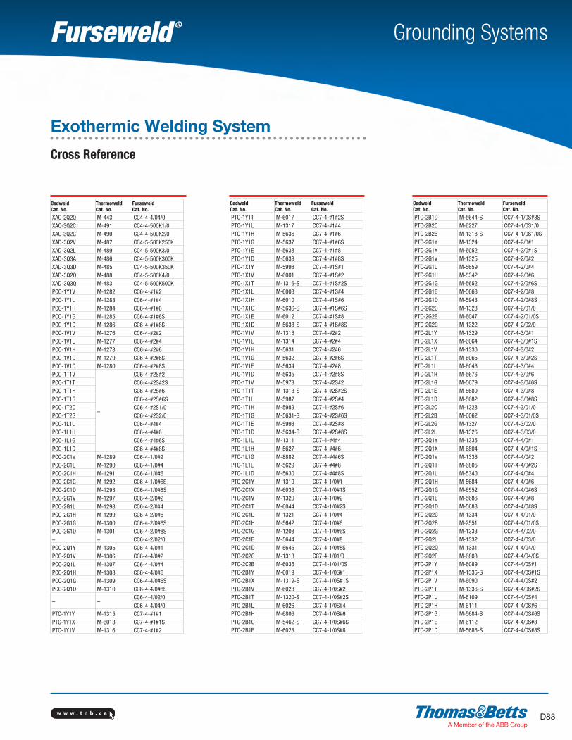
w w w . t n b . c a D83
Grounding Systems
Cadweld Cat. No.
Thermoweld Cat. No.
Furseweld Cat. No.
XAC-2Q2Q M-443 CC4-4-4/04/0XAC-3Q2C M-491 CC4-4-500K1/0XAC-3Q2G M-490 CC4-4-500K2/0XAD-3Q2V M-487 CC4-5-500K250KXAD-3Q2L M-489 CC4-5-500K3/0XAD-3Q3A M-486 CC4-5-500K300KXAD-3Q3D M-485 CC4-5-500K350KXAD-3Q2Q M-488 CC4-5-500K4/0XAD-3Q3Q M-483 CC4-5-500K500KPCC-1Y1V M-1282 CC6-4-#1#2PCC-1Y1L M-1283 CC6-4-#1#4PCC-1Y1H M-1284 CC6-4-#1#6PCC-1Y1G M-1285 CC6-4-#1#6SPCC-1Y1D M-1286 CC6-4-#1#8SPCC-1V1V M-1276 CC6-4-#2#2PCC-1V1L M-1277 CC6-4-#2#4PCC-1V1H M-1278 CC6-4-#2#6PCC-1V1G M-1279 CC6-4-#2#6SPCC-1V1D M-1280 CC6-4-#2#8SPCC-1T1V
–
CC6-4-#2S#2PCC-1T1T CC6-4-#2S#2SPCC-1T1H CC6-4-#2S#6PCC-1T1G CC6-4-#2S#6SPCC-1T2C CC6-4-#2S1/0PCC-1T2G CC6-4-#2S2/0PCC-1L1L CC6-4-#4#4PCC-1L1H CC6-4-#4#6PCC-1L1G CC6-4-#4#6SPCC-1L1D CC6-4-#4#8SPCC-2C1V M-1289 CC6-4-1/0#2PCC-2C1L M-1290 CC6-4-1/0#4PCC-2C1H M-1291 CC6-4-1/0#6PCC-2C1G M-1292 CC6-4-1/0#6SPCC-2C1D M-1293 CC6-4-1/0#8SPCC-2G1V M-1297 CC6-4-2/0#2PCC-2G1L M-1298 CC6-4-2/0#4PCC-2G1H M-1299 CC6-4-2/0#6PCC-2G1G M-1300 CC6-4-2/0#6SPCC-2G1D M-1301 CC6-4-2/0#8S– – CC6-4-2/02/0PCC-2Q1Y M-1305 CC6-4-4/0#1PCC-2Q1V M-1306 CC6-4-4/0#2PCC-2Q1L M-1307 CC6-4-4/0#4PCC-2Q1H M-1308 CC6-4-4/0#6PCC-2Q1G M-1309 CC6-4-4/0#6SPCC-2Q1D M-1310 CC6-4-4/0#8S
– –CC6-4-4/02/0CC6-4-4/04/0
PTC-1Y1Y M-1315 CC7-4-#1#1PTC-1Y1X M-6013 CC7-4-#1#1SPTC-1Y1V M-1316 CC7-4-#1#2
Cadweld Cat. No.
Thermoweld Cat. No.
Furseweld Cat. No.
PTC-1Y1T M-6017 CC7-4-#1#2SPTC-1Y1L M-1317 CC7-4-#1#4PTC-1Y1H M-5636 CC7-4-#1#6PTC-1Y1G M-5637 CC7-4-#1#6SPTC-1Y1E M-5638 CC7-4-#1#8PTC-1Y1D M-5639 CC7-4-#1#8SPTC-1X1Y M-5998 CC7-4-#1S#1PTC-1X1V M-6001 CC7-4-#1S#2PTC-1X1T M-1316-S CC7-4-#1S#2SPTC-1X1L M-6008 CC7-4-#1S#4PTC-1X1H M-6010 CC7-4-#1S#6PTC-1X1G M-5636-S CC7-4-#1S#6SPTC-1X1E M-6012 CC7-4-#1S#8PTC-1X1D M-5638-S CC7-4-#1S#8SPTC-1V1V M-1313 CC7-4-#2#2PTC-1V1L M-1314 CC7-4-#2#4PTC-1V1H M-5631 CC7-4-#2#6PTC-1V1G M-5632 CC7-4-#2#6SPTC-1V1E M-5634 CC7-4-#2#8PTC-1V1D M-5635 CC7-4-#2#8SPTC-1T1V M-5973 CC7-4-#2S#2PTC-1T1T M-1313-S CC7-4-#2S#2SPTC-1T1L M-5987 CC7-4-#2S#4PTC-1T1H M-5989 CC7-4-#2S#6PTC-1T1G M-5631-S CC7-4-#2S#6SPTC-1T1E M-5993 CC7-4-#2S#8PTC-1T1D M-5634-S CC7-4-#2S#8SPTC-1L1L M-1311 CC7-4-#4#4PTC-1L1H M-5627 CC7-4-#4#6PTC-1L1G M-8882 CC7-4-#4#6SPTC-1L1E M-5629 CC7-4-#4#8PTC-1L1D M-5630 CC7-4-#4#8SPTC-2C1Y M-1319 CC7-4-1/0#1PTC-2C1X M-6036 CC7-4-1/0#1SPTC-2C1V M-1320 CC7-4-1/0#2PTC-2C1T M-6044 CC7-4-1/0#2SPTC-2C1L M-1321 CC7-4-1/0#4PTC-2C1H M-5642 CC7-4-1/0#6PTC-2C1G M-1208 CC7-4-1/0#6SPTC-2C1E M-5644 CC7-4-1/0#8PTC-2C1D M-5645 CC7-4-1/0#8SPTC-2C2C M-1318 CC7-4-1/01/0PTC-2C2B M-6035 CC7-4-1/01/0SPTC-2B1Y M-6019 CC7-4-1/0S#1PTC-2B1X M-1319-S CC7-4-1/0S#1SPTC-2B1V M-6023 CC7-4-1/0S#2PTC-2B1T M-1320-S CC7-4-1/0S#2SPTC-2B1L M-6026 CC7-4-1/0S#4PTC-2B1H M-6806 CC7-4-1/0S#6PTC-2B1G M-5462-S CC7-4-1/0S#6SPTC-2B1E M-6028 CC7-4-1/0S#8
Cadweld Cat. No.
Thermoweld Cat. No.
Furseweld Cat. No.
PTC-2B1D M-5644-S CC7-4-1/0S#8SPTC-2B2C M-6227 CC7-4-1/0S1/0PTC-2B2B M-1318-S CC7-4-1/0S1/0SPTC-2G1Y M-1324 CC7-4-2/0#1PTC-2G1X M-6052 CC7-4-2/0#1SPTC-2G1V M-1325 CC7-4-2/0#2PTC-2G1L M-5659 CC7-4-2/0#4PTC-2G1H M-5342 CC7-4-2/0#6PTC-2G1G M-5652 CC7-4-2/0#6SPTC-2G1E M-5668 CC7-4-2/0#8PTC-2G1D M-5943 CC7-4-2/0#8SPTC-2G2C M-1323 CC7-4-2/01/0PTC-2G2B M-6047 CC7-4-2/01/0SPTC-2G2G M-1322 CC7-4-2/02/0PTC-2L1Y M-1329 CC7-4-3/0#1PTC-2L1X M-6064 CC7-4-3/0#1SPTC-2L1V M-1330 CC7-4-3/0#2PTC-2L1T M-6065 CC7-4-3/0#2SPTC-2L1L M-6046 CC7-4-3/0#4PTC-2L1H M-5676 CC7-4-3/0#6PTC-2L1G M-5679 CC7-4-3/0#6SPTC-2L1E M-5680 CC7-4-3/0#8PTC-2L1D M-5682 CC7-4-3/0#8SPTC-2L2C M-1328 CC7-4-3/01/0PTC-2L2B M-6062 CC7-4-3/01/0SPTC-2L2G M-1327 CC7-4-3/02/0PTC-2L2L M-1326 CC7-4-3/03/0PTC-2Q1Y M-1335 CC7-4-4/0#1PTC-2Q1X M-6804 CC7-4-4/0#1SPTC-2Q1V M-1336 CC7-4-4/0#2PTC-2Q1T M-6805 CC7-4-4/0#2SPTC-2Q1L M-5340 CC7-4-4/0#4PTC-2Q1H M-5684 CC7-4-4/0#6PTC-2Q1G M-6552 CC7-4-4/0#6SPTC-2Q1E M-5686 CC7-4-4/0#8PTC-2Q1D M-5688 CC7-4-4/0#8SPTC-2Q2C M-1334 CC7-4-4/01/0PTC-2Q2B M-2551 CC7-4-4/01/0SPTC-2Q2G M-1333 CC7-4-4/02/0PTC-2Q2L M-1332 CC7-4-4/03/0PTC-2Q2Q M-1331 CC7-4-4/04/0PTC-2Q2P M-6803 CC7-4-4/04/0SPTC-2P1Y M-6089 CC7-4-4/0S#1PTC-2P1X M-1335-S CC7-4-4/0S#1SPTC-2P1V M-6090 CC7-4-4/0S#2PTC-2P1T M-1336-S CC7-4-4/0S#2SPTC-2P1L M-6109 CC7-4-4/0S#4PTC-2P1H M-6111 CC7-4-4/0S#6PTC-2P1G M-5684-S CC7-4-4/0S#6SPTC-2P1E M-6112 CC7-4-4/0S#8PTC-2P1D M-5686-S CC7-4-4/0S#8S
Exothermic Welding System
Cross Reference
SectionD-grounding-systems.indd 83 6/6/2017 9:44:11 AM
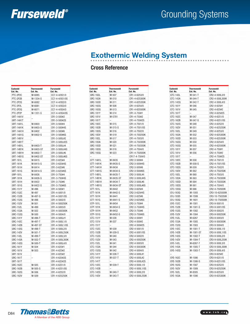
w w w . t n b . c aD84
Grounding Systems
Cadweld Cat. No.
Thermoweld Cat. No.
Furseweld Cat. No.
PTC-2P2C M-6085 CC7-4-4/0S1/0PTC-2P2B M-1334-S CC7-4-4/0S1/0SPTC-2P2G M-6082 CC7-4-4/0S2/0PTC-2P2L M-6081 CC7-4-4/0S3/0PTC-2P2Q M-6071 CC7-4-4/0S4/0PTC-2P2P M-1331-S CC7-4-4/0S4/0SGRT-14A1V
–CR1-3-500#2
GRT-14A1T CR1-3-500#2SGRT-14A1L M-8403 CR1-3-500#4GRT-14A1K M-8403-S CR1-3-500#4SGRT-14A1H M-8402 CR1-3-500#6GRT-14A1G M-8402-S CR1-3-500#6SGRT-14B1V
–CR1-3-500L#2
GRT-14B1T CR1-3-500L#2SGRT-14B1L M-8403-T CR1-3-500L#4GRT-14B1K M-8403-ST CR1-3-500L#4SGRT-14B1H M-8402-T CR1-3-500L#6GRT-14B1G M-8402-ST CR1-3-500L#6SGRT-161L M-8415 CR1-3-625#4GRT-161K M-8415-S CR1-3-625#4SGRT-161H M-8414 CR1-3-625#6GRT-161G M-8414-S CR1-3-625#6SGRP-181L M-8426 CR1-3-750#4GRP-181K M-8426-S CR1-3-750#4SGRT-181H M-8422 CR1-3-750#6GRT-181G M-8422-S CR1-3-750#6SGRC-151Y M-496 CR1-4-500#1GRC-152C M-497 CR1-4-5001/0GRC-152B M-497-S CR1-4-5001/0SGRC-152G M-498 CR1-4-5002/0GRC-152V M-501 CR1-4-500250KGRC-152L M-499 CR1-4-5003/0GRC-153A M-502 CR1-4-500300KGRC-152Q M-500 CR1-4-5004/0GRC-141Y M-496-T CR1-4-500L#1GRC-142C M-497-T CR1-4-500L1/0GRC-142B M-497-ST CR1-4-500L1/0SGRC-142G M-498-T CR1-4-500L2/0GRC-142V M-501-T CR1-4-500L250KGRC-142L M-499-T CR1-4-500L3/0GRC-143A M-502-T CR1-4-500L300KGRC-142Q M-500-T CR1-4-500L4/0GRC-161Y M-504 CR1-4-625#1GRC-161V M-503 CR1-4-625#2GRT-161V
–CR1-4-625#2
GRC-161T CR1-4-625#2SGRT-161T CR1-4-625#2SGRC-162C M-505 CR1-4-6251/0GRC-162B M-505-S CR1-4-6251/0SGRC-162G M-506 CR1-4-6252/0GRC-162V M-509 CR1-4-625250K
Cadweld Cat. No.
Thermoweld Cat. No.
Furseweld Cat. No.
GRC-162L M-507 CR1-4-6253/0GRC-163A M-510 CR1-4-625300KGRC-163D M-511 CR1-4-625350KGRC-162Q M-508 CR1-4-6254/0GRC-163Q M-513 CR1-4-625500KGRC-181Y M-514 CR1-4-750#1GRC-181V M-5781 CR1-4-750#2GRC-181T – CR1-4-750#2SGRC-182C M-515 CR1-4-7501/0GRC-182B M-515-S CR1-4-7501/0SGRC-182G M-516 CR1-4-7502/0GRC-182V M-519 CR1-4-750250KGRC-182L M-517 CR1-4-7503/0GRC-183A M-520 CR1-4-750300KGRC-183D M-521 CR1-4-750350KGRC-182Q M-518 CR1-4-7504/0GRC-183Q M-523 CR1-4-750500K– – CR17-4-7504/0GTT-14A1L M-8435 CR2-3-500#4GTT-14A1K M-8435-S CR2-3-500#4SGTT-14A1H M-8434 CR2-3-500#6GTT-14A1G M-8434-S CR2-3-500#6SGTT-14B1L M-8435-T CR2-3-500L#4GTT-14B1K M-8435-ST CR2-3-500L#4SGTT-14B1H M-8434-T CR2-3-500L#6GTT-14B1G M-8434-ST CR2-3-500L#6SGTT-161L M-8442 CR2-3-625#4GTT-161K M-8442-S CR2-3-625#4SGTT-161H M-8441 CR2-3-625#6GTT-161G M-8441-S CR2-3-625#6SGTP-181L M-8454 CR2-3-750#4GTP-181K M-8454-S CR2-3-750#4SGTP-181H M-8452 CR2-3-750#6GTP-181G M-8452-S CR2-3-750#6SGTC-151Y M-538 CR2-4-500#1GTC-151V M-537 CR2-4-500#2GTC-151T – CR2-4-500#2SGTC-152C M-539 CR2-4-5001/0GTC-152B M-539-S CR2-4-5001/0SGTC-152G M-540 CR2-4-5002/0GTC-152V M-543 CR2-4-500250KGTC-152L M-541 CR2-4-5003/0GTC-153A M-544 CR2-4-500300KGTC-152Q M-542 CR2-4-5004/0GTC-141Y M-538-T CR2-4-500L#1GTC-141V M-537-T CR2-4-500L#2GTC-141T – CR2-4-500L#2SGTC-142C M-539-T CR2-4-500L1/0GTC-142B – CR2-4-500L1/0SGTC-142G M-540-T CR2-4-500L2/0GTC-142V M-543-T CR2-4-500L250K
Cadweld Cat. No.
Thermoweld Cat. No.
Furseweld Cat. No.
GTC-142L M-541-T CR2-4-500L3/0GTC-143A M-544-T CR2-4-500L300KGTC-142Q M-542-T CR2-4-500L4/0GTC-161Y M-546 CR2-4-625#1GTC-161V M-545 CR2-4-625#2GTC-161T – CR2-4-625#2SGTC-162C M-547 CR2-4-6251/0GTC-162B M-547-S CR2-4-6251/0SGTC-162G M-548 CR2-4-6252/0GTC-162V M-551 CR2-4-625250KGTC-162L M-549 CR2-4-6253/0GTC-163A M-552 CR2-4-625300KGTC-163D M-553 CR2-4-625350KGTC-162Q M-550 CR2-4-6254/0GTC-163Q M-555 CR2-4-625500KGTC-181Y M-557 CR2-4-750#1GTC-181V M-556 CR2-4-750#2GTC-181T – CR2-4-750#2SGTC-182C M-558 CR2-4-7501/0GTC-182B M-558-S CR2-4-7501/0SGTC-182G M-559 CR2-4-7502/0GTC-182V M-562 CR2-4-750250KGTC-182L M-560 CR2-4-7503/0GTC-183A M-563 CR2-4-750300KGTC-183D M-564 CR2-4-750350KGTC-182Q M-561 CR2-4-7504/0GTC-183Q M-566 CR2-4-750500KGYJ-163Q M-1593 CR3-10-625500KGYJ-183D M-1599 CR3-10-750350KGYJ-183Q M-1601 CR3-10-750500KGYE-152C M-1581 CR3-9-5001/0GYE-152B M-1581-S CR3-9-5001/0SGYE-152G M-1582 CR3-9-5002/0GYE-152V M-1584 CR3-9-500250KGYE-152L M-6267 CR3-9-5003/0GYE-153A M-1585 CR3-9-500300KGYE-152Q M-1583 CR3-9-5004/0GYE-142C M-1581-T CR3-9-500L1/0GYE-142B M-1581-ST CR3-9-500L1/0SGYE-142G M-1582-T CR3-9-500L2/0GYE-142V M-1584-T CR3-9-500L250KGYE-142L M-6267-T CR3-9-500L3/0GYE-143A M-1585-T CR3-9-500L300KGYE-142Q M-1583-T CR3-9-500L4/0– – CR3-9-625#2GYE-162C M-1586 CR3-9-6251/0GYE-162B M-1586-S CR3-9-6251/0SGYE-162G M-1587 CR3-9-6252/0GYE-162V M-1589 CR3-9-625250KGYE-162L M-8305 CR3-9-6253/0GYE-163A M-1590 CR3-9-625300K
Exothermic Welding System
Cross Reference
SectionD-grounding-systems.indd 84 6/6/2017 9:44:11 AM
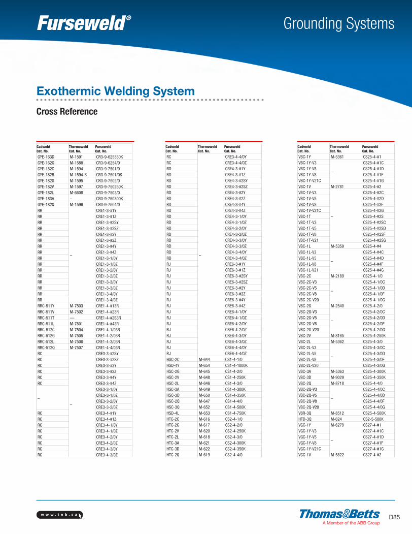
w w w . t n b . c a D85
Grounding Systems
Cadweld Cat. No.
Thermoweld Cat. No.
Furseweld Cat. No.
GYE-163D M-1591 CR3-9-625350KGYE-162Q M-1588 CR3-9-6254/0GYE-182C M-1594 CR3-9-7501/0GYE-182B M-1594-S CR3-9-7501/0SGYE-182G M-1595 CR3-9-7502/0GYE-182V M-1597 CR3-9-750250KGYE-182L M-6608 CR3-9-7503/0GYE-183A – CR3-9-750300KGYE-182Q M-1596 CR3-9-7504/0RR
–
CRE1-3-#1YRR CRE1-3-#1ZRR CRE1-3-#2SYRR CRE1-3-#2SZRR CRE1-3-#2YRR CRE1-3-#2ZRR CRE1-3-#4YRR CRE1-3-#4ZRR CRE1-3-1/0YRR CRE1-3-1/0ZRR CRE1-3-2/0YRR CRE1-3-2/0ZRR CRE1-3-3/0YRR CRE1-3-3/0ZRR CRE1-3-4/0YRR CRE1-3-4/0ZRRC-511Y M-7503 CRE1-4-#13RRRC-511V M-7502 CRE1-4-#23RRRC-511T — CRE1-4-#2S3RRRC-511L M-7501 CRE1-4-#43RRRC-512C M-7504 CRE1-4-1/03RRRC-512G M-7505 CRE1-4-2/03RRRC-512L M-7506 CRE1-4-3/03RRRC-512Q M-7507 CRE1-4-4/03RRC
–
CRE3-3-#2SYRC CRE3-3-#2SZRC CRE3-3-#2YRC CRE3-3-#2ZRC CRE3-3-#4YRC CRE3-3-#4Z
–
CRE3-3-1/0YCRE3-3-1/0ZCRE3-3-2/0YCRE3-3-2/0Z
RC CRE3-4-#1YRC CRE3-4-#1ZRC CRE3-4-1/0YRC CRE3-4-1/0ZRC CRE3-4-2/0YRC CRE3-4-2/0ZRC CRE3-4-3/0YRC CRE3-4-3/0Z
Cadweld Cat. No.
Thermoweld Cat. No.
Furseweld Cat. No.
RC
–
CRE3-4-4/0YRC CRE3-4-4/0ZRD CRE4-3-#1YRD CRE4-3-#1ZRD CRE4-3-#2SYRD CRE4-3-#2SZRD CRE4-3-#2YRD CRE4-3-#2ZRD CRE4-3-#4YRD CRE4-3-#4ZRD CRE4-3-1/0YRD CRE4-3-1/0ZRD CRE4-3-2/0YRD CRE4-3-2/0ZRD CRE4-3-3/0YRD CRE4-3-3/0ZRD CRE4-3-4/0YRD CRE4-3-4/0ZRJ CRE6-3-#1YRJ CRE6-3-#1ZRJ CRE6-3-#2SYRJ CRE6-3-#2SZRJ CRE6-3-#2YRJ CRE6-3-#2ZRJ CRE6-3-#4YRJ CRE6-3-#4ZRJ CRE6-4-1/0YRJ CRE6-4-1/0ZRJ CRE6-4-2/0YRJ CRE6-4-2/0ZRJ CRE6-4-3/0YRJ CRE6-4-3/0ZRJ CRE6-4-4/0YRJ CRE6-4-4/0ZHSC-2C M-644 CS1-4-1/0HSD-4Y M-654 CS1-4-1000KHSC-2G M-645 CS1-4-2/0HSC-2V M-648 CS1-4-250KHSC-2L M-646 CS1-4-3/0HSC-3A M-649 CS1-4-300KHSC-3D M-650 CS1-4-350KHSC-2Q M-647 CS1-4-4/0HSC-3Q M-652 CS1-4-500KHSD-4L M-653 CS1-4-750KHTC-2C M-616 CS2-4-1/0HTC-2G M-617 CS2-4-2/0HTC-2V M-620 CS2-4-250KHTC-2L M-618 CS2-4-3/0HTC-3A M-621 CS2-4-300KHTC-3D M-622 CS2-4-350KHTC-2Q M-619 CS2-4-4/0
Cadweld Cat. No.
Thermoweld Cat. No.
Furseweld Cat. No.
VBC-1Y M-5361 CS25-4-#1VBC-1Y-V3
–
CS25-4-#1CVBC-1Y-V5 CS25-4-#1DVBC-1Y-V8 CS25-4-#1FVBC-1Y-V21C CS25-4-#1GVBC-1V M-2781 CS25-4-#2VBC-1V-V3
–
CS25-4-#2CVBC-1V-V5 CS25-4-#2DVBC-1V-V8 CS25-4-#2FVBC-1V-V21C CS25-4-#2GVBC-1T CS25-4-#2SVBC-1T-V3 CS25-4-#2SCVBC-1T-V5 CS25-4-#2SDVBC-1T-V8 CS25-4-#2SFVBC-1T-V21 CS25-4-#2SGVBC-1L M-5359 CS25-4-#4VBC-1L-V3
–
CS25-4-#4CVBC-1L-V5 CS25-4-#4DVBC-1L-V8 CS25-4-#4FVBC-1L-V21 CS25-4-#4GVBC-2C M-2189 CS25-4-1/0VBC-2C-V3
–
CS25-4-1/0CVBC-2C-V5 CS25-4-1/0DVBC-2C-V8 CS25-4-1/0FVBC-2C-V20 CS25-4-1/0GVBC-2G M-2540 CS25-4-2/0VBC-2G-V3
–
CS25-4-2/0CVBC-2G-V5 CS25-4-2/0DVBC-2G-V8 CS25-4-2/0FVBC-2G-V20 CS25-4-2/0GVBC-2V M-8165 CS25-4-250KVBC-2L M-5362 CS25-4-3/0VBC-2L-V3
–
CS25-4-3/0CVBC-2L-V5 CS25-4-3/0DVBC-2L-V8 CS25-4-3/0FVBC-2L-V20 CS25-4-3/0GVBC-3A M-5363 CS25-4-300KVBC-3D M-9029 CS25-4-350KVBC-2Q M-8718 CS25-4-4/0VBC-2Q-V3
–
CS25-4-4/0CVBC-2Q-V5 CS25-4-4/0DVBC-2Q-V8 CS25-4-4/0FVBC-2Q-V20 CS25-4-4/0GVBR-3Q M-8512 CS25-4-500KHTD-3Q M-624 CS2-5-500KVGC-1Y M-6279 CS27-4-#1VGC-1Y-V3
–
CS27-4-#1CVGC-1Y-V5 CS27-4-#1DVGC-1Y-V8 CS27-4-#1FVGC-1Y-V21C CS27-4-#1GVGC-1V M-5822 CS27-4-#2
Exothermic Welding System
Cross Reference
SectionD-grounding-systems.indd 85 6/6/2017 9:44:12 AM
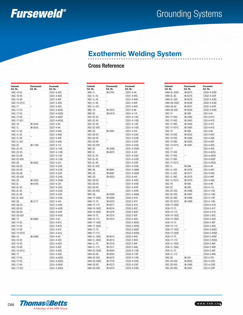
w w w . t n b . c aD86
Grounding Systems
Cadweld Cat. No.
Thermoweld Cat. No.
Furseweld Cat. No.
VNC-1L M-2761 CS31-4-#4VGC-1L-V3
–
CS31-4-#4CVGC-1L-V5 CS31-4-#4DVGC-1L-V8 CS31-4-#4FVGC-1L-V21 CS31-4-#4GVNC-1H M-5910 CS31-4-#6VNC-2C M-5419 CS31-4-1/0VGC-2C-V3
–
CS31-4-1/0CVGC-2C-V5 CS31-4-1/0DVGC-2C-V8 CS31-4-1/0FVGC-2C-V20 CS31-4-1/0GVNC-2G M-2567 CS31-4-2/0VGC-2G-V3
–
CS31-4-2/0CVGC-2G-V5 CS31-4-2/0DVGC-2G-V8 CS31-4-2/0FVGC-2G-V20 CS31-4-2/0GVNC-2V M-2568 CS31-4-250KVNC-2L M-6072 CS31-4-3/0VGC-2L-V3
–
CS31-4-3/0CVGC-2L-V5 CS31-4-3/0DVGC-2L-V8 CS31-4-3/0FVGC-2L-V20 CS31-4-3/0GVNC-3A M-6061 CS31-4-300KVNC-3D M-6067 CS31-4-350KVNC-2Q M-9253 CS31-4-4/0VGC-2Q-V3
–
CS31-4-4/0CVGC-2Q-V5 CS31-4-4/0DVGC-2Q-V8 CS31-4-4/0FVGC-2Q-V20 CS31-4-4/0GVNC-3Q M-8359 CS31-4-500KHAA-1Y-325C M-6269 CS32-2-#1DHAA-1Y-7C M-6270 CS32-2-#1FHAA-1Y-11C M-6271 CS32-2-#1GHAA-1V-162C M-6016 CS32-2-#2CHAA-1V-350C M-2576 CS32-2-#2DHAA-1V-7C M-2514 CS32-2-#2FHAA-1V-11C M-2515 CS32-2-#2GHAA-1T-162C
–
CS32-2-#2SCHAA-1T-350C CS32-2-#2SDHAA-1T-7C CS32-2-#2SFHAA-1T-11C CS32-2-#2SGHAA-1L-162C M-8014 CS32-2-#4CHAA-1L-350C M-8015 CS32-2-#4DHAA-1L-7C M-2516 CS32-2-#4FHAA-1L-11C M-2517 CS32-2-#4GHAH-2C-350C M-8504 CS32-4-1/0DHAH-2C-8C M-8505 CS32-4-1/0FHAH-2C-20C M-6272 CS32-4-1/0GHAH-2G-350C M-2776 CS32-4-2/0DHAH-2G-8C M-6273 CS32-4-2/0FHAH-2G-20C M-6274 CS32-4-2/0G
Cadweld Cat. No.
Thermoweld Cat. No.
Furseweld Cat. No.
VGC-1V-V3
–
CS27-4-#2CVGC-1V-V5 CS27-4-#2DVGC-1V-V8 CS27-4-#2FVGC-1V-V21C CS27-4-#2GVGC-1T CS27-4-#2SVGC-1T-V3 CS27-4-#2SCVGC-1T-V5 CS27-4-#2SDVGC-1T-V8 CS27-4-#2SFVGC-1T-V21 CS27-4-#2SGVGC-1H M-5245 CS27-4-#4VGC-1L M-5816 CS27-4-#4VGC-1L-V3
–
CS27-4-#4CVGC-1L-V5 CS27-4-#4DVGC-1L-V8 CS27-4-#4FVGC-1L-V21 CS27-4-#4GVGC-2C M-1168 CS27-4-1/0VGC-2C-V3
–
CS27-4-1/0CVGC-2C-V5 CS27-4-1/0DVGC-2C-V8 CS27-4-1/0FVGC-2C-V20 CS27-4-1/0GVGC-2G M-9242 CS27-4-2/0VGC-2G-V3
–
CS27-4-2/0CVGC-2G-V5 CS27-4-2/0DVGC-2G-V8 CS27-4-2/0FVGC-2G-V20 CS27-4-2/0GVGC-2V M-2520 CS27-4-250KVGC-2L M-6195 CS27-4-3/0VGC-2L-V3
–
CS27-4-3/0CVGC-2L-V5 CS27-4-3/0DVGC-2L-V8 CS27-4-3/0FVGC-2L-V20 CS27-4-3/0GVGC-2Q M-2177 CS27-4-4/0VGC-2Q-V3
–
CS27-4-4/0CVGC-2Q-V5 CS27-4-4/0DVGC-2Q-V8 CS27-4-4/0FVGC-2Q-V20 CS27-4-4/0GVNC-1Y M-6060 CS31-4-#1VGC-1Y-V3
–
CS31-4-#1CVGC-1Y-V5 CS31-4-#1DVGC-1Y-V8 CS31-4-#1FVGC-1Y-V21C CS31-4-#1GVNC-1V M-2569 CS31-4-#2VGC-1V-V3
–
CS31-4-#2CVGC-1V-V5 CS31-4-#2DVGC-1V-V8 CS31-4-#2FVGC-1V-V21C CS31-4-#2GVNC-1T CS31-4-#2SVGC-1T-V3 CS31-4-#2SCVGC-1T-V5 CS31-4-#2SDVGC-1T-V8 CS31-4-#2SFVGC-1T-V21 CS31-4-#2SG
Cadweld Cat. No.
Thermoweld Cat. No.
Furseweld Cat. No.
HAH-2L-350C M-6275 CS32-4-3/0DHAH-2L-8C M-6276 CS32-4-3/0FHAH-2L-20C M-6278 CS32-4-3/0GHAH-2Q-350C M-9236 CS32-4-4/0DHAH-2Q-8C M-9237 CS32-4-4/0FHAH-2Q-20C M-9238 CS32-4-4/0GVSC-1Y M-589 CS3-4-#1VSC-1Y-V3C M-2482 CS3-4-#1CVSC-1Y-V5C M-2483 CS3-4-#1DVSC-1Y-V8C M-2484 CS3-4-#1FVSC-1Y-V21C M-2485 CS3-4-#1GVSC-1V M-588 CS3-4-#2VSC-1V-V3C M-9233 CS3-4-#2CVSC-1V-V5C M-2480 CS3-4-#2DVSC-1V-V8C M-2583 CS3-4-#2FVSC-1V-V21C M-2481 CS3-4-#2GVSC-1T
–
CS3-4-#2SVSC-1T-V3C CS3-4-#2SCVSC-1T-V5C CS3-4-#2SDVSC-1T-V8C CS3-4-#2SFVSC-1T-V21C CS3-4-#2SGVSC-1L M-586 CS3-4-#4VSC-1L-V3C M-2476 CS3-4-#4CVSC-1L-V5C M-2477 CS3-4-#4DVSC-1L-V8C M-2478 CS3-4-#4FVSC-1L-V21C M-2479 CS3-4-#4GVSC-1H M-585 CS3-4-#6VSC-2C M-590 CS3-4-1/0VSC-2C-V3C M-2486 CS3-4-1/0CVSC-2C-V5C M-2487 CS3-4-1/0DVSC-2C-V8C M-2488 CS3-4-1/0FVSC-2C-V21C M-2489 CS3-4-1/0GHCA-1Y-350C
–
CS34-2-#1DHCA-1Y-7C CS34-2-#1FHCA-1Y-11C CS34-2-#1GHCA-1V-162C CS34-2-#2CHCA-1V-350C CS34-2-#2DHCA-1V-7C CS34-2-#2FHCA-1V-11C CS34-2-#2GHCA-1T-162C CS34-2-#2SCHCA-1T-350C CS34-2-#2SDHCA-1T-7C CS34-2-#2SFHCA-1T-11C CS34-2-#2SGHCA-1L-162C CS34-2-#4CHCA-1L-350C CS34-2-#4DHCA-1L-7C CS34-2-#4FHCA-1L-11C CS34-2-#4GVSC-2G M-591 CS3-4-2/0VSC-2G-V3C M-8833 CS3-4-2/0CVSC-2G-V5C M-2490 CS3-4-2/0DVSC-2G-V8C M-2491 CS3-4-2/0F
Exothermic Welding System
Cross Reference
SectionD-grounding-systems.indd 86 6/6/2017 9:44:12 AM
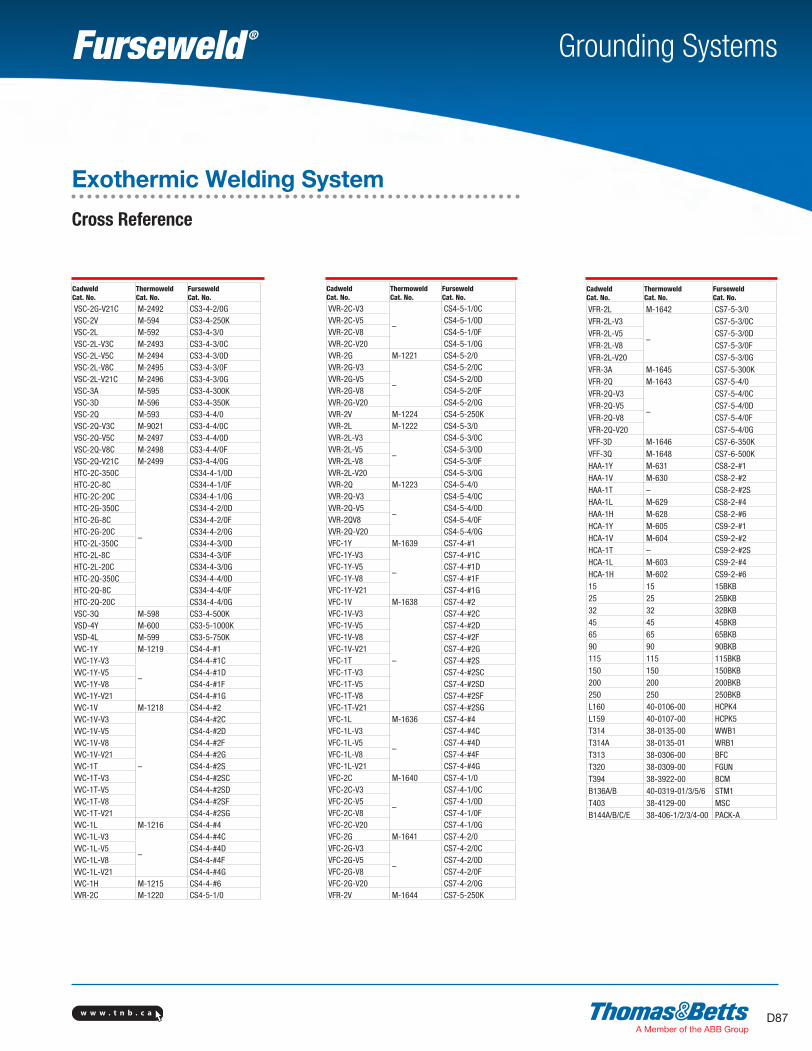
w w w . t n b . c a D87
Grounding Systems
Cadweld Cat. No.
Thermoweld Cat. No.
Furseweld Cat. No.
VSC-2G-V21C M-2492 CS3-4-2/0GVSC-2V M-594 CS3-4-250KVSC-2L M-592 CS3-4-3/0VSC-2L-V3C M-2493 CS3-4-3/0CVSC-2L-V5C M-2494 CS3-4-3/0DVSC-2L-V8C M-2495 CS3-4-3/0FVSC-2L-V21C M-2496 CS3-4-3/0GVSC-3A M-595 CS3-4-300KVSC-3D M-596 CS3-4-350KVSC-2Q M-593 CS3-4-4/0VSC-2Q-V3C M-9021 CS3-4-4/0CVSC-2Q-V5C M-2497 CS3-4-4/0DVSC-2Q-V8C M-2498 CS3-4-4/0FVSC-2Q-V21C M-2499 CS3-4-4/0GHTC-2C-350C
–
CS34-4-1/0DHTC-2C-8C CS34-4-1/0FHTC-2C-20C CS34-4-1/0GHTC-2G-350C CS34-4-2/0DHTC-2G-8C CS34-4-2/0FHTC-2G-20C CS34-4-2/0GHTC-2L-350C CS34-4-3/0DHTC-2L-8C CS34-4-3/0FHTC-2L-20C CS34-4-3/0GHTC-2Q-350C CS34-4-4/0DHTC-2Q-8C CS34-4-4/0FHTC-2Q-20C CS34-4-4/0GVSC-3Q M-598 CS3-4-500KVSD-4Y M-600 CS3-5-1000KVSD-4L M-599 CS3-5-750KVVC-1Y M-1219 CS4-4-#1VVC-1Y-V3
–
CS4-4-#1CVVC-1Y-V5 CS4-4-#1DVVC-1Y-V8 CS4-4-#1FVVC-1Y-V21 CS4-4-#1GVVC-1V M-1218 CS4-4-#2VVC-1V-V3
–
CS4-4-#2CVVC-1V-V5 CS4-4-#2DVVC-1V-V8 CS4-4-#2FVVC-1V-V21 CS4-4-#2GVVC-1T CS4-4-#2SVVC-1T-V3 CS4-4-#2SCVVC-1T-V5 CS4-4-#2SDVVC-1T-V8 CS4-4-#2SFVVC-1T-V21 CS4-4-#2SGVVC-1L M-1216 CS4-4-#4VVC-1L-V3
–
CS4-4-#4CVVC-1L-V5 CS4-4-#4DVVC-1L-V8 CS4-4-#4FVVC-1L-V21 CS4-4-#4GVVC-1H M-1215 CS4-4-#6VVR-2C M-1220 CS4-5-1/0
Cadweld Cat. No.
Thermoweld Cat. No.
Furseweld Cat. No.
VVR-2C-V3
–
CS4-5-1/0CVVR-2C-V5 CS4-5-1/0DVVR-2C-V8 CS4-5-1/0FVVR-2C-V20 CS4-5-1/0GVVR-2G M-1221 CS4-5-2/0VVR-2G-V3
–
CS4-5-2/0CVVR-2G-V5 CS4-5-2/0DVVR-2G-V8 CS4-5-2/0FVVR-2G-V20 CS4-5-2/0GVVR-2V M-1224 CS4-5-250KVVR-2L M-1222 CS4-5-3/0VVR-2L-V3
–
CS4-5-3/0CVVR-2L-V5 CS4-5-3/0DVVR-2L-V8 CS4-5-3/0FVVR-2L-V20 CS4-5-3/0GVVR-2Q M-1223 CS4-5-4/0VVR-2Q-V3
–
CS4-5-4/0CVVR-2Q-V5 CS4-5-4/0DVVR-2QV8 CS4-5-4/0FVVR-2Q-V20 CS4-5-4/0GVFC-1Y M-1639 CS7-4-#1VFC-1Y-V3
–
CS7-4-#1CVFC-1Y-V5 CS7-4-#1DVFC-1Y-V8 CS7-4-#1FVFC-1Y-V21 CS7-4-#1GVFC-1V M-1638 CS7-4-#2VFC-1V-V3
–
CS7-4-#2CVFC-1V-V5 CS7-4-#2DVFC-1V-V8 CS7-4-#2FVFC-1V-V21 CS7-4-#2GVFC-1T CS7-4-#2SVFC-1T-V3 CS7-4-#2SCVFC-1T-V5 CS7-4-#2SDVFC-1T-V8 CS7-4-#2SFVFC-1T-V21 CS7-4-#2SGVFC-1L M-1636 CS7-4-#4VFC-1L-V3
–
CS7-4-#4CVFC-1L-V5 CS7-4-#4DVFC-1L-V8 CS7-4-#4FVFC-1L-V21 CS7-4-#4GVFC-2C M-1640 CS7-4-1/0VFC-2C-V3
–
CS7-4-1/0CVFC-2C-V5 CS7-4-1/0DVFC-2C-V8 CS7-4-1/0FVFC-2C-V20 CS7-4-1/0GVFC-2G M-1641 CS7-4-2/0VFC-2G-V3
–
CS7-4-2/0CVFC-2G-V5 CS7-4-2/0DVFC-2G-V8 CS7-4-2/0FVFC-2G-V20 CS7-4-2/0GVFR-2V M-1644 CS7-5-250K
Cadweld Cat. No.
Thermoweld Cat. No.
Furseweld Cat. No.
VFR-2L M-1642 CS7-5-3/0VFR-2L-V3
–
CS7-5-3/0CVFR-2L-V5 CS7-5-3/0DVFR-2L-V8 CS7-5-3/0FVFR-2L-V20 CS7-5-3/0GVFR-3A M-1645 CS7-5-300KVFR-2Q M-1643 CS7-5-4/0VFR-2Q-V3
–
CS7-5-4/0CVFR-2Q-V5 CS7-5-4/0DVFR-2Q-V8 CS7-5-4/0FVFR-2Q-V20 CS7-5-4/0GVFF-3D M-1646 CS7-6-350KVFF-3Q M-1648 CS7-6-500KHAA-1Y M-631 CS8-2-#1HAA-1V M-630 CS8-2-#2HAA-1T – CS8-2-#2SHAA-1L M-629 CS8-2-#4HAA-1H M-628 CS8-2-#6HCA-1Y M-605 CS9-2-#1HCA-1V M-604 CS9-2-#2HCA-1T – CS9-2-#2SHCA-1L M-603 CS9-2-#4HCA-1H M-602 CS9-2-#615 15 15BKB25 25 25BKB32 32 32BKB45 45 45BKB65 65 65BKB90 90 90BKB115 115 115BKB150 150 150BKB200 200 200BKB250 250 250BKBL160 40-0106-00 HCPK4L159 40-0107-00 HCPK5T314 38-0135-00 WWB1T314A 38-0135-01 WRB1T313 38-0306-00 BFCT320 38-0309-00 FGUNT394 38-3922-00 BCMB136A/B 40-0319-01/3/5/6 STM1T403 38-4129-00 MSCB144A/B/C/E 38-406-1/2/3/4-00 PACK-A
Exothermic Welding System
Cross Reference
SectionD-grounding-systems.indd 87 6/6/2017 9:44:12 AM
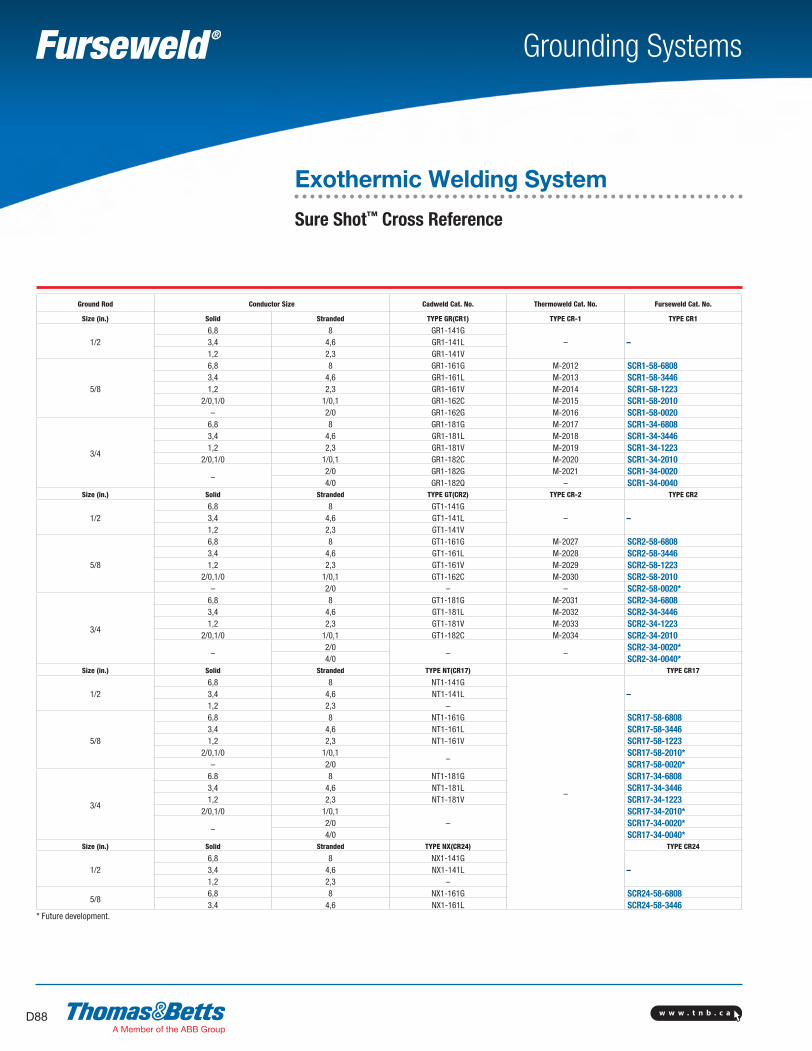
w w w . t n b . c aD88
Grounding Systems
Ground Rod Conductor Size Cadweld Cat. No. Thermoweld Cat. No. Furseweld Cat. No.
Size (in.) Solid Stranded TYPE GR(CR1) TYPE CR-1 TYPE CR1
1/26,8 8 GR1-141G
– –3,4 4,6 GR1-141L1,2 2,3 GR1-141V
5/8
6,8 8 GR1-161G M-2012 SCR1-58-68083,4 4,6 GR1-161L M-2013 SCR1-58-34461,2 2,3 GR1-161V M-2014 SCR1-58-1223
2/0,1/0 1/0,1 GR1-162C M-2015 SCR1-58-2010– 2/0 GR1-162G M-2016 SCR1-58-0020
3/4
6,8 8 GR1-181G M-2017 SCR1-34-68083,4 4,6 GR1-181L M-2018 SCR1-34-34461,2 2,3 GR1-181V M-2019 SCR1-34-1223
2/0,1/0 1/0,1 GR1-182C M-2020 SCR1-34-2010
–2/0 GR1-182G M-2021 SCR1-34-00204/0 GR1-182Q – SCR1-34-0040
Size (in.) Solid Stranded TYPE GT(CR2) TYPE CR-2 TYPE CR2
1/26,8 8 GT1-141G
– –3,4 4,6 GT1-141L1,2 2,3 GT1-141V
5/8
6,8 8 GT1-161G M-2027 SCR2-58-68083,4 4,6 GT1-161L M-2028 SCR2-58-34461,2 2,3 GT1-161V M-2029 SCR2-58-1223
2/0,1/0 1/0,1 GT1-162C M-2030 SCR2-58-2010– 2/0 – – SCR2-58-0020*
3/4
6,8 8 GT1-181G M-2031 SCR2-34-68083,4 4,6 GT1-181L M-2032 SCR2-34-34461,2 2,3 GT1-181V M-2033 SCR2-34-1223
2/0,1/0 1/0,1 GT1-182C M-2034 SCR2-34-2010
–2/0
– –SCR2-34-0020*
4/0 SCR2-34-0040*Size (in.) Solid Stranded TYPE NT(CR17) TYPE CR17
1/26,8 8 NT1-141G
–
–3,4 4,6 NT1-141L1,2 2,3 –
5/8
6,8 8 NT1-161G SCR17-58-68083,4 4,6 NT1-161L SCR17-58-34461,2 2,3 NT1-161V SCR17-58-1223
2/0,1/0 1/0,1–
SCR17-58-2010*– 2/0 SCR17-58-0020*
3/4
6.8 8 NT1-181G SCR17-34-68083,4 4,6 NT1-181L SCR17-34-34461,2 2,3 NT1-181V SCR17-34-1223
2/0,1/0 1/0,1–
SCR17-34-2010*
–2/0 SCR17-34-0020*4/0 SCR17-34-0040*
Size (in.) Solid Stranded TYPE NX(CR24) TYPE CR24
1/26,8 8 NX1-141G
–3,4 4,6 NX1-141L1,2 2,3 –
5/86,8 8 NX1-161G SCR24-58-68083,4 4,6 NX1-161L SCR24-58-3446
* Future development.
Exothermic Welding System
Sure Shot™ Cross Reference
SectionD-grounding-systems.indd 88 6/6/2017 9:44:13 AM
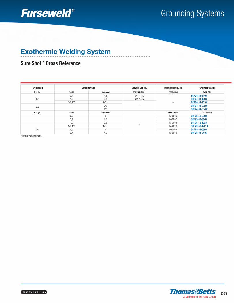
w w w . t n b . c a D89
Grounding Systems
Ground Rod Conductor Size Cadweld Cat. No. Thermoweld Cat. No. Furseweld Cat. No.
Size (in.) Solid Stranded TYPE GR(CR1) TYPE CR-1 TYPE CR1
3/43,4 4,6 NX1-181L
–
SCR24-34-34461,2 2,3 NX1-181V SCR24-34-1223
2/0,1/0 1/0,1–
SCR24-34-2010*
5/8 –2/0 SCR24-34-0020*4/0 SCR24-34-0040*
Size (in.) Solid Stranded TYPE CR-25 TYPE CR25
6,8 8
–
M-2006 SCR25-58-68083,4 4,6 M-2007 SCR25-58-34461,2 2,3 M-2008 SCR25-58-1223
3/42/0,1/0 1/0,1 M-2023 SCR25-58-12010
6,8 8 M-2068 SCR25-34-68083,4 4,6 M-2069 SCR25-34-3446
* Future development.
Exothermic Welding System
Sure Shot™ Cross Reference
SectionD-grounding-systems.indd 89 6/6/2017 9:44:13 AM
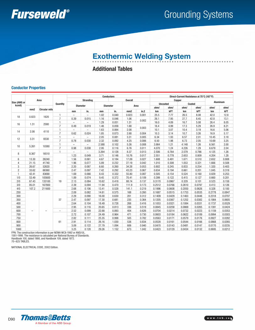
w w w . t n b . c aD90
Grounding Systems
Conductor Properties
Size (AWG or kcmil)
AreaQuantity
Conductors Direct-Current Resistance at 75°C (167°F)Stranding Overall Copper
AluminumDiameter Diameter Area
Uncoated Coated
mm2 Circular milsohm/ ohm/ ohm/ ohm/ ohm/ ohm/
mm in. mm in. mm2 in.2 km kFT km kFT km kFT
18 0.823 16201 – – 1.02 0.040 0.823 0.001 25.5 7.77 26.5 8.08 42.0 12.87 0.39 0.015 1.16 0.046 1.06
0.00226.1 7.95 27.7 8.45 42.8 13.1
16 1.31 25801 – – 1.29 0.051 1.31 16.0 4.89 16.7 5.08 26.4 8.057 0.49 0.019 1.46 0.058 1.68
0.00316.4 4.99 17.3 5.29 26.9 8.21
14 2.08 41101 – – 1.63 0.064 2.08 10.1 3.07 10.4 3.19 16.6 5.067 0.62 0.024 1.85 0.073 2.68 0.004 10.3 3.14 10.7 3.26 16.9 5.17
12 3.31 65301 – – 2.05 0.081 3.31 0.005 6.34 1.93 6.57 2.01 10.45 3.187 0.78 0.030 2.32 0.092 4.25 0.006 6.50 1.98 6.73 2.05 10.69 3.25
10 5.261 103801 – – 2.588 0.102 5.26 0.008 3.984 1.21 4.148 1.26 6.561 2.007 0.98 0.038 2.95 0.116 6.76 0.011 4.070 1.24 4.226 1.29 6.679 2.04
8 8.367 165101 – – 3.264 0.128 8.37 0.013 2.506 0.764 2.579 0.786 4.125 1.26
7
1.23 0.049 3.71 0.146 10.76 0.017 2.551 0.778 2.653 0.809 4.204 1.286 13.30 26240 1.56 0.061 4.67 0.184 17.09 0.027 1.608 0.491 1.671 0.510 2.652 0.8084 21.15 41740 1.96 0.077 5.89 0.232 27.19 0.042 1.010 0.308 1.053 0.321 1.666 0.5083 26.67 52620 2.20 0.087 6.60 0.260 34.28 0.053 0.802 0.245 0.833 0.254 1.320 0.4032 33.62 66360 2.47 0.097 7.42 0.292 43.23 0.067 0.634 0.194 0.661 0.201 1.045 0.3191 42.41 83690
19
1.69 0.066 8.43 0.332 55.80 0.087 0.505 0.154 0.524 0.160 0.829 0.2531/0 53.49 105600 1.89 0.074 9.45 0.372 70.41 0.109 0.399 0.122 0.415 0.127 0.660 0.2012/0 67.43 133100 2.13 0.084 10.62 0.418 88.74 0.137 0.3170 0.0967 0.329 0.101 0.523 0.1593/0 85.01 167800 2.39 0.094 11.94 0.470 111.9 0.173 0.2512 0.0766 0.2610 0.0797 0.413 0.1264/0 107.2 211600 2.68 0.106 13.41 0.528 141.1 0.219 0.1996 0.0608 0.2050 0.0626 0.328 0.100250
– –
37
2.09 0.082 14.61 0.575 168 0.260 0.1687 0.0515 0.1753 0.0535 0.2778 0.0847300 2.29 0.090 16.00 0.630 201 0.312 0.1409 0.0429 0.1463 0.0446 0.2318 0.0707350 2.47 0.097 17.30 0.681 235 0.364 0.1205 0.0367 0.1252 0.0382 0.1984 0.0605400 2.64 0.104 18.49 0.728 268 0.416 0.1053 0.0321 0.1084 0.0331 0.1737 0.0529500 2.95 0.116 20.65 0.813 336 0.519 0.0845 0.0258 0.0869 0.0265 0.1391 0.0424600 – 2.52 0.099 22.68 0.893 404 0.626 0.0704 0.0214 0.0732 0.0223 0.1159 0.0353700
61
2.72 0.107 24.49 0.964 471 0.730 0.0603 0.0184 0.0622 0.0189 0.0994 0.0303750 2.82 0.111 25.35 0.998 505 0.782 0.0563 0.0171 0.0579 0.0176 0.0927 0.0282800 2.91 0.114 26.16 1.030 538 0.834 0.0528 0.0161 0.0544 0.0166 0.0868 0.0265900 3.09 0.122 27.79 1.094 606 0.940 0.0470 0.0143 0.0481 0.0147 0.0770 0.02351000 3.25 0.128 29.26 1.152 673 1.042 0.0423 0.0129 0.0434 0.0132 0.0695 0.0212
FPN: The construction information is per NEMA WC8-1992 or ANSI/UL. 1581-1998. The resistance is calculated per National Bureau of Standards.Handbook 100, dated 1966, and Handbook 109, dated 1972.70–625 TABLES.
NATIONAL ELECTRICAL CODE, 2002 Edition.
Exothermic Welding System
Additional Tables
SectionD-grounding-systems.indd 90 6/6/2017 9:44:13 AM

w w w . t n b . c a D91
Grounding Systems
Metric Conductors
Wire SizeCirc Mils # of
StrandsStrand
DiameterDiameter Colour
CodeDie
CodeMM AWG MM Inch
10 8 19,731 3.57 3.57 0.140
Red 217 1.35 4.05 0.159
16 6 31,5581 4.50 4.50 0.177
Blue 247
1.70 5.10 0.200
25 2 49,3252.14 6.42 0.253 Gray 29
19
1.35 6.75 0.266 Brown 3335 1 69,055 1.53 7.65 0.300 Green 3750 1/0 98,65 1.78 8.90 0.350 Pink 4270 2/0 138,11 2.14 10.70 0.421 Black 45
953/0
187,52.52 12.60 0.496
Orange 503/0
371.78 12.46 0.490
120 250 236,76 2.03 14.21 0.560 Purple 54150 300 295,95 2.25 15.75 0.620 White 66185 – 365
61
2.52 17.64 0.695 Red 71240 500 473,5 2.25 20.25 0.797 Brown 87300
–
591,9 2.52 22.68 0.893 Green 94
400 789,22.85 25.65 1.000
Black 10691 2.36 25.96 1.022
500 986,561 3.20 28.80 1.134
–
12591 2.65 29.15 1.148
–630 1,243,000
1272.52 32.76 1.290
800 1,578,400 2.85 37.05 1.4591000 1,973,000 3.20 41.60 1.638
Table B.310.1 Ampacities of Two or Three Insulated Conductors, Rated 0 Through 2000 V, Within an Overall Covering (Multiconductor Cable), in Raceway in Free Air Based on Ambient Air Temperature of 30°C (86°F)
Temperature Rating of Conductor
Size (AWG or kcmil)
60°C (140°F)
75°C (167°F)
90°C (194°F)
60°C (140°F)
75°C (167°F)
90°C (194°F)
Size (AWG or kcmil)
Types TW, UF
Types RHW, THHW, THW,
THWN, XHHW,
ZW
Types THHN, THHW, THW-2, THWN-2,
RHH, RWH-2, USE-2, XHHN,
XHHW-2, ZW-2
TypeTW
Types RHW, THHW, THW,
THWN, XHHW
Types THHN, THHW, THW-2, THWN-2,
RHH, RWH-2, USE-2, XHHW, XHHW,
XHHW-2, ZW-2
CopperAluminum or Copper-
Clad Aluminum
14 16* 18* 21* – – – 1412 20* 24* 27* 16* 18* 21* 1210 27* 33* 36* 21* 25* 28* 108 36 43 48 28 33 37 86 48 58 65 38 45 51 64 66 79 89 51 61 69 43 76 90 102 59 70 79 32 88 105 119 69 83 93 21 102 121 137 80 95 106 1
1/0 121 145 163 94 113 127 1/02/0 138 166 186 108 129 146 2/03/0 158 189 214 124 147 167 3/04/0 187 223 253 147 176 197 4/0250 205 245 276 160 192 217 250300 234 281 317 185 221 250 300350 255 305 345 202 242 273 350400 274 328 371 218 261 295 400500 315 378 427 254 303 342 500600 343 413 468 279 335 378 600700 376 452 514 310 371 420 700750 387 466 529 321 384 435 750800 397 479 543 331 397 450 800900 415 500 570 350 421 477 9001000 448 542 617 382 460 521 1000
Correction FactorsAmbient
Temp. (°C)For ambient temperatures other than 30°C (86°F), multiply the
ampacities shown above by the appropriate factor shown below.Ambient
Temp. (°C)21–25 1.08 1.05 1.04 1.08 1.05 1.04 70–7726–30 1.00 1.00 1.00 1.00 1.00 1.00 79–8631–35 0.91 0.94 0.96 0.91 0.94 0.96 88–9536–40 0.82 0.88 0.91 0.82 0.88 0.91 97–10441–45 0.71 0.82 0.87 0.71 0.82 0.87 106–11346–50 0.58 0.75 0.82 0.58 0.75 0.82 115–122
* Unless otherwise specifically permitted elsewhere in this Code, the overcurrent protection for these conductor types shall not exceed 15 A for 14 AWG, 20 A for 12 AWG, and 30 A for 10 AWG copper; or 15 A for 12 AWG and 25 A for 10 AWG aluminum and copper-clad aluminum.
NATIONAL ELECTRICAL CODE, 2002 Edition.
Exothermic Welding System
Additional Tables
SectionD-grounding-systems.indd 91 6/6/2017 9:44:14 AM
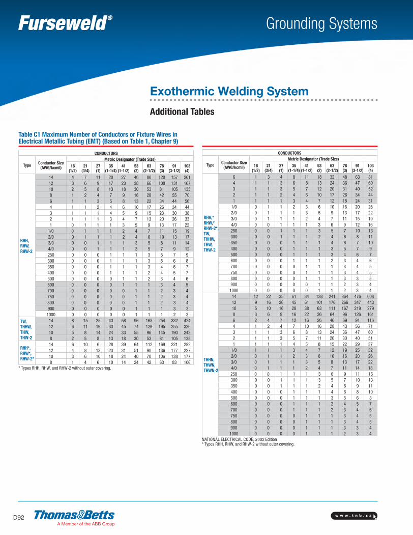
w w w . t n b . c aD92
Grounding Systems
CONDUCTORS
Type Conductor Size (AWG/kcmil)
Metric Designator (Trade Size)
16(1/2)
21(3/4)
27(1)
35(1-1/4)
41(1-1/2)
53(2)
63(2-1/2)
78(3)
91(3-1/2)
103(4)
RHH, RHW, RHW-2
14 4 7 11 20 27 46 80 120 157 20112 3 6 9 17 23 38 66 100 131 16710 2 5 8 13 18 30 53 81 105 1358 1 2 4 7 9 16 28 42 55 706 1 1 3 5 8 13 22 34 44 564 1 1 2 4 6 10 17 26 34 443 1 1 1 4 5 9 15 23 30 382 1 1 1 3 4 7 13 20 26 331 0 1 1 1 3 5 9 13 17 22
1/0 0 1 1 1 2 4 7 11 15 192/0 0 1 1 1 2 4 6 10 13 173/0 0 0 1 1 1 3 5 8 11 144/0 0 0 1 1 1 3 5 7 9 12250 0 0 0 1 1 1 3 5 7 9300 0 0 0 1 1 1 3 5 6 8350 0 0 0 1 1 1 3 4 6 7400 0 0 0 1 1 1 2 4 5 7500 0 0 0 0 1 1 2 3 4 6600 0 0 0 0 1 1 1 3 4 5700 0 0 0 0 0 1 1 2 3 4750 0 0 0 0 0 1 1 2 3 4800 0 0 0 0 0 1 1 2 3 4900 0 0 0 0 0 1 1 1 3 3
1000 0 0 0 0 0 1 1 1 2 3
TW, THHW, THW, THW-2
14 8 15 25 43 58 96 168 254 332 42412 6 11 19 33 45 74 129 195 255 32610 5 8 14 24 33 55 96 145 190 2438 2 5 8 13 18 30 53 81 105 135
RHH*, RHW*, RHW-2*
14 6 10 6 28 39 64 112 169 221 28212 4 8 13 23 31 51 90 136 177 22710 3 6 10 18 24 40 70 106 138 1778 1 4 6 10 14 24 42 63 83 106
* Types RHH, RHW, and RHW-2 without outer covering.
Table C1 Maximum Number of Conductors or Fixture Wires in Electrical Metallic Tubing (EMT) (Based on Table 1, Chapter 9)
CONDUCTORS
Type Conductor Size (AWG/kcmil)
Metric Designator (Trade Size)
16(1/2)
21(3/4)
27(1)
35(1-1/4)
41(1-1/2)
53(2)
63(2-1/2)
78(3)
91(3-1/2)
103(4)
RHH,*RHW,* RHW-2*,TW, THHW, THW, THW-2
6 1 3 4 8 11 18 32 48 63 814 1 1 3 6 8 13 24 36 47 603 1 1 3 5 7 12 20 31 40 522 1 1 2 4 6 10 17 26 34 441 1 1 1 3 4 7 12 18 24 31
1/0 0 1 1 2 3 6 10 16 20 262/0 0 1 1 1 3 5 9 13 17 223/0 0 1 1 1 2 4 7 11 15 194/0 0 0 1 1 1 3 6 9 12 16250 0 0 1 1 1 3 5 7 10 13300 0 0 1 1 1 2 4 6 8 11350 0 0 0 1 1 1 4 6 7 10400 0 0 0 1 1 1 3 5 7 9500 0 0 0 1 1 1 3 4 6 7600 0 0 0 1 1 1 2 3 4 6700 0 0 0 0 1 1 1 3 4 5750 0 0 0 0 1 1 1 3 4 5800 0 0 0 0 1 1 1 3 3 5900 0 0 0 0 0 1 1 2 3 4
1000 0 0 0 0 0 1 1 2 3 4
THHN, THWN, THWN-2
14 12 22 35 61 84 138 241 364 476 60812 9 16 26 45 61 101 176 266 347 44310 5 10 16 28 38 63 111 167 219 2798 3 6 9 16 22 36 64 96 126 1616 2 4 7 12 16 26 46 69 91 1164 1 2 4 7 10 16 28 43 56 713 1 1 3 6 8 13 24 36 47 602 1 1 3 5 7 11 20 30 40 511 1 1 1 4 5 8 15 22 29 37
1/0 1 1 1 3 4 7 12 19 25 322/0 0 1 1 2 3 6 10 16 20 263/0 0 1 1 1 3 5 8 13 17 224/0 0 1 1 1 2 4 7 11 14 18250 0 0 1 1 1 3 6 9 11 15300 0 0 1 1 1 3 5 7 10 13350 0 0 1 1 1 2 4 6 9 11400 0 0 0 1 1 1 4 6 8 10500 0 0 0 1 1 1 3 5 6 8600 0 0 0 1 1 1 2 4 5 7700 0 0 0 1 1 1 2 3 4 6750 0 0 0 0 1 1 1 3 4 5800 0 0 0 0 1 1 1 3 4 5900 0 0 0 0 1 1 1 3 3 4
1000 0 0 0 0 1 1 1 2 3 4NATIONAL ELECTRICAL CODE, 2002 Edition* Types RHH, RHW, and RHW-2 without outer covering.
Exothermic Welding System
Additional Tables
SectionD-grounding-systems.indd 92 6/6/2017 9:44:14 AM
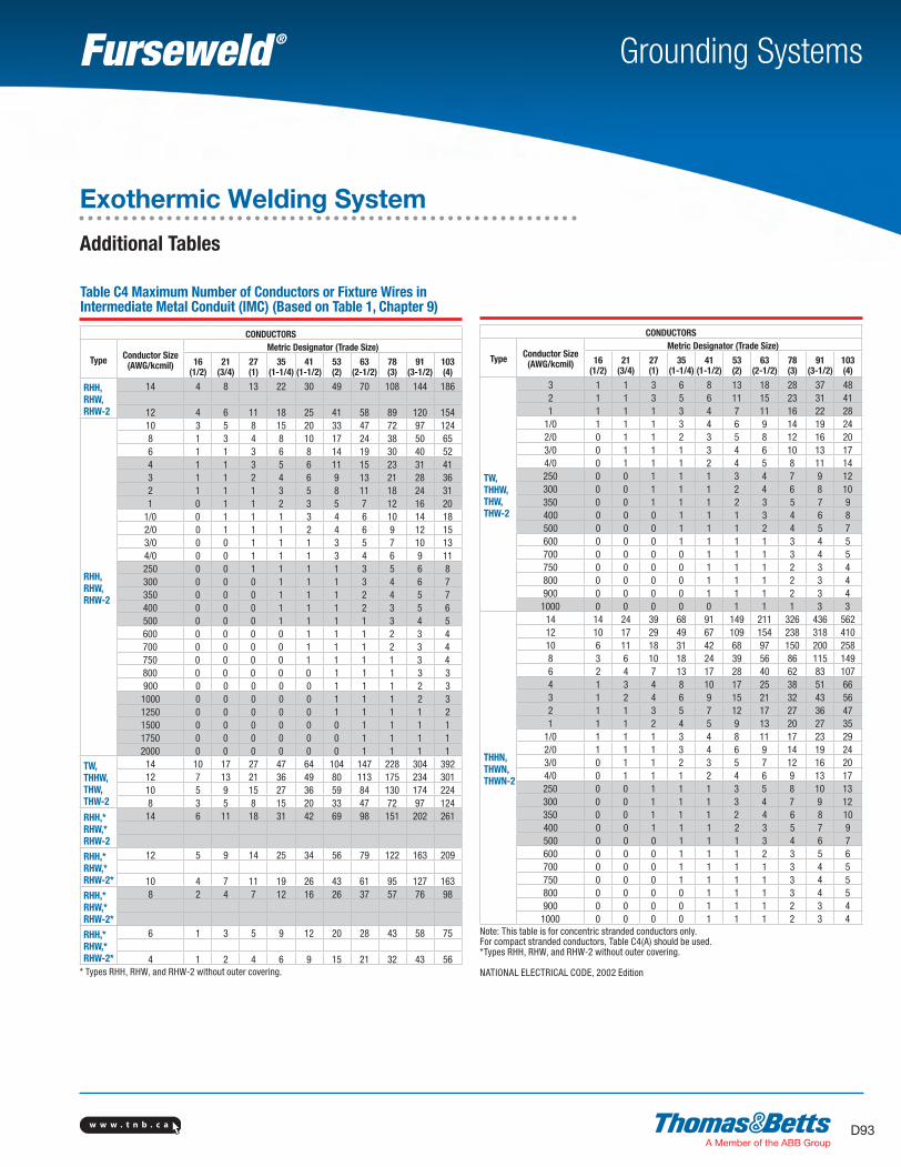
w w w . t n b . c a D93
Grounding Systems
CONDUCTORS
Type Conductor Size (AWG/kcmil)
Metric Designator (Trade Size)
16(1/2)
21(3/4)
27(1)
35(1-1/4)
41(1-1/2)
53(2)
63(2-1/2)
78(3)
91(3-1/2)
103(4)
RHH, RHW, RHW-2
14 4 8 13 22 30 49 70 108 144 186
12 4 6 11 18 25 41 58 89 120 154
RHH, RHW, RHW-2
10 3 5 8 15 20 33 47 72 97 1248 1 3 4 8 10 17 24 38 50 656 1 1 3 6 8 14 19 30 40 524 1 1 3 5 6 11 15 23 31 413 1 1 2 4 6 9 13 21 28 362 1 1 1 3 5 8 11 18 24 311 0 1 1 2 3 5 7 12 16 20
1/0 0 1 1 1 3 4 6 10 14 182/0 0 1 1 1 2 4 6 9 12 153/0 0 0 1 1 1 3 5 7 10 134/0 0 0 1 1 1 3 4 6 9 11250 0 0 1 1 1 1 3 5 6 8300 0 0 0 1 1 1 3 4 6 7350 0 0 0 1 1 1 2 4 5 7400 0 0 0 1 1 1 2 3 5 6500 0 0 0 1 1 1 1 3 4 5600 0 0 0 0 1 1 1 2 3 4700 0 0 0 0 1 1 1 2 3 4750 0 0 0 0 1 1 1 1 3 4800 0 0 0 0 0 1 1 1 3 3900 0 0 0 0 0 1 1 1 2 3
1000 0 0 0 0 0 1 1 1 2 31250 0 0 0 0 0 1 1 1 1 21500 0 0 0 0 0 0 1 1 1 11750 0 0 0 0 0 0 1 1 1 12000 0 0 0 0 0 0 1 1 1 1
TW, THHW, THW, THW-2
14 10 17 27 47 64 104 147 228 304 39212 7 13 21 36 49 80 113 175 234 30110 5 9 15 27 36 59 84 130 174 2248 3 5 8 15 20 33 47 72 97 124
RHH,* RHW,* RHW-2
14 6 11 18 31 42 69 98 151 202 261
RHH,* RHW,* RHW-2*
12 5 9 14 25 34 56 79 122 163 209
10 4 7 11 19 26 43 61 95 127 163RHH,* RHW,* RHW-2*
8 2 4 7 12 16 26 37 57 76 98
RHH,* RHW,* RHW-2*
6 1 3 5 9 12 20 28 43 58 75
4 1 2 4 6 9 15 21 32 43 56* Types RHH, RHW, and RHW-2 without outer covering.
Table C4 Maximum Number of Conductors or Fixture Wires in Intermediate Metal Conduit (IMC) (Based on Table 1, Chapter 9)
CONDUCTORS
Type Conductor Size (AWG/kcmil)
Metric Designator (Trade Size)
16(1/2)
21(3/4)
27(1)
35(1-1/4)
41(1-1/2)
53(2)
63(2-1/2)
78(3)
91(3-1/2)
103(4)
TW, THHW, THW, THW-2
3 1 1 3 6 8 13 18 28 37 482 1 1 3 5 6 11 15 23 31 411 1 1 1 3 4 7 11 16 22 28
1/0 1 1 1 3 4 6 9 14 19 242/0 0 1 1 2 3 5 8 12 16 203/0 0 1 1 1 3 4 6 10 13 174/0 0 1 1 1 2 4 5 8 11 14250 0 0 1 1 1 3 4 7 9 12300 0 0 1 1 1 2 4 6 8 10350 0 0 1 1 1 2 3 5 7 9400 0 0 0 1 1 1 3 4 6 8500 0 0 0 1 1 1 2 4 5 7600 0 0 0 1 1 1 1 3 4 5700 0 0 0 0 1 1 1 3 4 5750 0 0 0 0 1 1 1 2 3 4800 0 0 0 0 1 1 1 2 3 4900 0 0 0 0 1 1 1 2 3 4
1000 0 0 0 0 0 1 1 1 3 3
THHN, THWN, THWN-2
14 14 24 39 68 91 149 211 326 436 56212 10 17 29 49 67 109 154 238 318 41010 6 11 18 31 42 68 97 150 200 2588 3 6 10 18 24 39 56 86 115 1496 2 4 7 13 17 28 40 62 83 1074 1 3 4 8 10 17 25 38 51 663 1 2 4 6 9 15 21 32 43 562 1 1 3 5 7 12 17 27 36 471 1 1 2 4 5 9 13 20 27 35
1/0 1 1 1 3 4 8 11 17 23 292/0 1 1 1 3 4 6 9 14 19 243/0 0 1 1 2 3 5 7 12 16 204/0 0 1 1 1 2 4 6 9 13 17250 0 0 1 1 1 3 5 8 10 13300 0 0 1 1 1 3 4 7 9 12350 0 0 1 1 1 2 4 6 8 10400 0 0 1 1 1 2 3 5 7 9500 0 0 0 1 1 1 3 4 6 7600 0 0 0 1 1 1 2 3 5 6700 0 0 0 1 1 1 1 3 4 5750 0 0 0 1 1 1 1 3 4 5800 0 0 0 0 1 1 1 3 4 5900 0 0 0 0 1 1 1 2 3 4
1000 0 0 0 0 1 1 1 2 3 4Note: This table is for concentric stranded conductors only. For compact stranded conductors, Table C4(A) should be used.*Types RHH, RHW, and RHW-2 without outer covering.
NATIONAL ELECTRICAL CODE, 2002 Edition
Exothermic Welding System
Additional Tables
SectionD-grounding-systems.indd 93 6/6/2017 9:44:15 AM
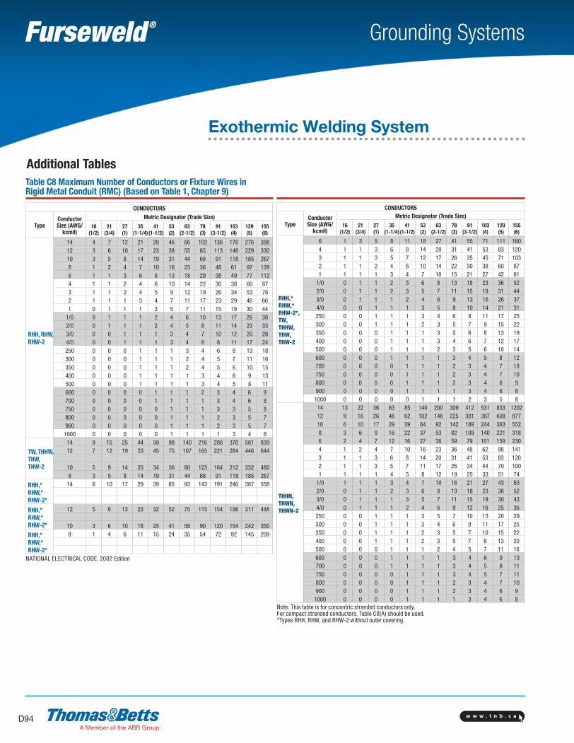
w w w . t n b . c aD94
Grounding Systems
Additional Tables
CONDUCTORS
TypeConductor Size (AWG/
kcmil)
Metric Designator (Trade Size)
16(1/2)
21(3/4)
27(1)
35(1-1/4)
41(1-1/2)
53(2)
63(2-1/2)
78(3)
91(3-1/2)
103(4)
129(5)
155(6)
RHH, RHW, RHW-2
14 4 7 12 21 28 46 66 102 136 176 276 39812 3 6 10 17 23 38 55 85 113 146 229 33010 3 5 8 14 19 31 44 68 91 118 185 2678 1 2 4 7 10 16 23 36 48 61 97 1396 1 1 3 6 8 13 18 29 38 49 77 1124 1 1 2 4 6 10 14 22 30 38 60 873 1 1 2 4 5 9 12 19 26 34 53 762 1 1 1 3 4 7 11 17 23 29 46 661 0 1 1 1 3 5 7 11 15 19 30 44
1/0 0 1 1 1 2 4 6 10 13 17 26 382/0 0 1 1 1 2 4 5 8 11 14 23 333/0 0 0 1 1 1 3 4 7 10 12 20 284/0 0 0 1 1 1 3 4 6 8 11 17 24250 0 0 0 1 1 1 3 4 6 8 13 18300 0 0 0 1 1 1 2 4 5 7 11 16350 0 0 0 1 1 1 2 4 5 6 10 15400 0 0 0 1 1 1 1 3 4 6 9 13500 0 0 0 1 1 1 1 3 4 5 8 11600 0 0 0 0 1 1 1 2 3 4 6 9700 0 0 0 0 1 1 1 1 3 4 6 8750 0 0 0 0 0 1 1 1 3 3 5 8800 0 0 0 0 0 1 1 1 2 3 5 7900 0 0 0 0 0 1 1 1 2 3 5 71000 0 0 0 0 0 1 1 1 1 3 4 6
TW, THHW, THW, THW-2
14 9 15 25 44 59 98 140 216 288 370 581 83912 7 12 19 33 45 75 107 165 221 284 446 644
10 5 9 14 25 34 56 80 123 164 212 332 4808 3 5 8 14 19 31 44 68 91 118 185 267
RHH,* RHW,* RHW-2*
14 6 10 17 29 39 65 93 143 191 246 387 558
RHH,* RHW,* RHW-2*
12 5 8 13 23 32 52 75 115 154 198 311 448
10 3 6 10 18 25 41 58 90 120 154 242 350
RHH,* RHW,* RHW-2*
8 1 4 6 11 15 24 35 54 72 92 145 209
NATIONAL ELECTRICAL CODE, 2002 Edition
Table C8 Maximum Number of Conductors or Fixture Wires in Rigid Metal Conduit (RMC) (Based on Table 1, Chapter 9)
CONDUCTORS
TypeConductor Size (AWG/
kcmil)
Metric Designator (Trade Size)
16(1/2)
21(3/4)
27(1)
35(1-1/4)
41(1-1/2)
53(2)
63(2-1/2)
78(3)
91(3-1/2)
103(4)
129(5)
155(6)
RHH,* RHW,* RHW-2*,TW, THHW, THW, THW-2
6 1 3 5 8 11 18 27 41 55 71 111 1604 1 1 3 6 8 14 20 31 41 53 83 1203 1 1 3 5 7 12 17 26 35 45 71 1032 1 1 2 4 6 10 14 22 30 38 60 871 1 1 1 3 4 7 10 15 21 27 42 61
1/0 0 1 1 2 3 6 8 13 18 23 36 522/0 0 1 1 2 3 5 7 11 15 19 31 443/0 0 1 1 1 2 4 6 9 13 16 26 374/0 0 0 1 1 1 3 5 8 10 14 21 31250 0 0 1 1 1 3 4 6 8 11 17 25300 0 0 1 1 1 2 3 5 7 9 15 22350 0 0 0 1 1 1 3 5 6 8 13 19400 0 0 0 1 1 1 3 4 6 7 12 17500 0 0 0 1 1 1 2 3 5 6 10 14600 0 0 0 1 1 1 1 3 4 5 8 12700 0 0 0 0 1 1 1 2 3 4 7 10750 0 0 0 0 1 1 1 2 3 4 7 10800 0 0 0 0 1 1 1 2 3 4 6 9900 0 0 0 0 1 1 1 1 3 4 6 8
1000 0 0 0 0 0 1 1 1 2 3 5 8
THHN, THWN, THWN-2
14 13 22 36 63 85 140 200 309 412 531 833 120212 9 16 26 46 62 102 146 225 301 387 608 87710 6 10 17 29 39 64 92 142 189 244 383 5528 3 6 9 16 22 37 53 82 109 140 221 3186 2 4 7 12 16 27 38 59 79 101 159 2304 1 2 4 7 10 16 23 36 48 62 98 1413 1 1 3 6 8 14 20 31 41 53 83 1202 1 1 3 5 7 11 17 26 34 44 70 1001 1 1 1 4 5 8 12 19 25 33 51 74
1/0 1 1 1 3 4 7 10 16 21 27 43 632/0 0 1 1 2 3 6 8 13 18 23 36 523/0 0 1 1 1 3 5 7 11 15 19 30 434/0 0 1 1 1 2 4 6 9 12 16 25 36250 0 0 1 1 1 3 5 7 10 13 20 29300 0 0 1 1 1 3 4 6 8 11 17 25350 0 0 1 1 1 2 3 5 7 10 15 22400 0 0 1 1 1 2 3 5 7 8 13 20500 0 0 0 1 1 1 2 4 5 7 11 16600 0 0 0 1 1 1 1 3 4 6 9 13700 0 0 0 1 1 1 1 3 4 5 8 11750 0 0 0 0 1 1 1 3 4 5 7 11800 0 0 0 0 1 1 1 2 3 4 7 10900 0 0 0 0 1 1 1 2 3 4 6 9
1000 0 0 0 0 1 1 1 1 3 4 6 8Note: This table is for concentric stranded conductors only. For compact stranded conductors, Table C8(A) should be used.*Types RHH, RHW, and RHW-2 without outer covering.
Exothermic Welding System
SectionD-grounding-systems.indd 94 6/6/2017 9:44:17 AM
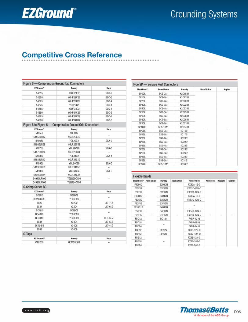
w w w . t n b . c a D95
Grounding SystemsEZGround ®
Competitive Cross Reference
Figure 6 — Compression Ground Tap ConnectorsEZGround® Burndy Ilsco
54855 YGHP29C2 GGC-2
54860 YGHP29C26 GGC-354865 YGHP29C29 GGC-454875 YGHP2C2 GGC-154885 YGHP34C2 GGC-554890 YGHP34C26 GGC-654895 YGHP34C29 GGC-754900 YGHP34C34 GGC-8
Figure 6 to Figure 6 — Compression Ground Grid ConnectorsEZGround® Burndy Ilsco
54855L YGL2C2–
54855LR12 YGLR29C1254865L YGL29C2 GGA-2
54865LR58 YGLR29C58 –54875L YGL29C29 GGA-3
54875LR34 YGLR29C34 –54885L YGL34C2 GGA-4
54885LR12 YGLR34C12 –54895L YGL34C29 GGA-5
54895LR58 YGLR34C58 –54900L YGL34C34 GGA-6
54900LR34 YGLR34C34–54910LR100 YGLR29C100
54920LR100 YGLR34C100
C-Crimp Series BCEZGround® Burndy Ilsco
BC202 YC26C2–
BC2020-BB YC26C26BC22 YC2C2 ULT-7-ZBC24 YC2C4 ULT-6-ZBC402 YC28C2
–BC4020 YC28C26BC4040 YC28C28 ULT-12-ZBC44 YC4C4 ULT-5-Z
BC46-BB YC4C6 ULT-4-ZBC48 YC4C8 –
C-TapsEZ Ground® Burndy Ilsco
CTG250 GCM28CG3 –
Type SP — Service Post ConnectorsBlackburn® Penn Union Burndy Ilsco/Utilco Kupler
SP0DL SCS-0A1 K2C15B1
– –
SP1DL SCS-1A1 K2C17B1SP2DL SCS-2A1 K2C20B1SP3DL SCS-3A1 K2C22B1SP4DL SCS-4A1 K2C23B1SP5DL SCS-5A1 K2C25B1SP6DL SCS-6A1 K2C26B1SP8DL SCS-8A1 K2C28B1SP9DL SCS-9A1 K2C31B1SP10DL SCS-10A1 K2C34B1SP0SL SSS-0A1 KC15B1SP1SL SSS-1A1 KC17B1SP2SL SSS-2A1 KC20B1SP3SL SSS-3A1 KC22B1SP4SL SSS-4A1 KC23B1SP5SL SSS-5A1 KC25B1SP6SL SSS-6A1 KC26B1SP8SL SSS-8A1 KC28B1SP9SL SSS-9A1 KC31B1SP10SL SSS-10A1 KC34B1
Flexible BraidsBlackburn® Penn Union Burndy Ilsco/Utilco Penn-Union Anderson Dossert Gedney
FB2D12
–
B2D12N
–
FXB2A-12-Q
– – –
FB2E12 B2E12N FXB2C-12N-Q
FB2F12 B2F12N FXB2D-12N-Q
FB3D12 B3D12N FXB3A-12-Q
FB3E12 B3E12N FXB3C-12N-Q
FB3F12 B3F12N–
FB3XD12 B4D12NFB4E12 B4E12N FXB4C-12N-Q
FB4F12 B4F12N FXB4D-12N-Q
FBD12 BD12N FXBA-12-QFBD18
–FXBA-18-Q
FBD24 FXBA-24-Q
FBE12 BE12N FXBB-12N-QFBF12 BF12N FXBD-12N-QFBG12
–FXBE-12N-Q
FBG18 FXBE-18S-QFBG24 FXBE-24S-Q
SectionD-grounding-systems.indd 95 6/6/2017 9:44:17 AM

w w w . t n b . c aD96
Grounding SystemsEZGround ®
Competitive Cross Reference
Ground PlatesEZGround® Burndy
– – – – – –GP2250-2 YGF29-2N
GP2250-4 YGF29-4N
GP250500-2 YGF34-2N
GP250500-4 YGF34-4N
Figure 8 — Compression Tap Connectors for Copper Ground RodsEZGround® Burndy
– – – – – –
GR1-202 YGHR26C100
GR12-202 YGHR26C12
GR12-40250 YGHR29C12
GR1-300500 YGHR34C100
GR1-40250 YGHR29C100
GR34-202 YGHR26C34
GR34-300500 YGHR34C34
GR34-40250 YGHR29C34
GR58-202 YGHR26C58
GR58-300500 YGHR34C58
GR58-40250 YGHR29C58
Type TBGS — Structural Grounding Studs EZGround® Burndy
– – – – – –
TBGS14 GSTUD14HY
TBGS34 GSTUD34HY
TBGS38 GSTUD38HY
TBGS58 GSTUD916HY
Type JAB — Ground Rod ClampsBlackburn® Penn Union Burndy Ilsco Eritech Anderson Joslyn Dossert
JAB12 CAB-1 GRC12 CGRC48 HDC12
–
J8391AB GNA50
JAB58 CAB-2 GRC58 CGRC58 – J8392AB GNA62
JAB34 CAB-3 – – HDC34 J8393AB GNA75
JAB34C–
GRC3426 CGRC68– – –
JAB1
– –
JAB12H CAB-1 HDC12 GC-103-01 J8491AB GN-50
JAB58H CAB-2 HDC58R GC-103-02 A8393AB GN-62
JAB34H CAB-3 HDC34 GC-103-03 J8493AB GN-75
JAB1H – – – – –
Type G — Budget Line Ground Rod ClampsBlackburn® Penn Union Burndy Ilsco Eritech Anderson Joslyn Dossert
G3 CAB-1 GRC12 – CP38 –
–
–
G4 CEB-1 GRC-12 GRC-48 CP12 GC-4 GNL50
G5 CEB-2 GRC-58 GRC-58 CP58 GC-5 GNL62
G6 CEB-3 GRC34 GRC-68 CP34 GC-6 GNL75
Blackburn and EZGround are registered trademarks fo Thomas & Betts Corporation.All other trademarks are the property of their respective owners.
SectionD-grounding-systems.indd 96 6/6/2017 9:44:18 AM
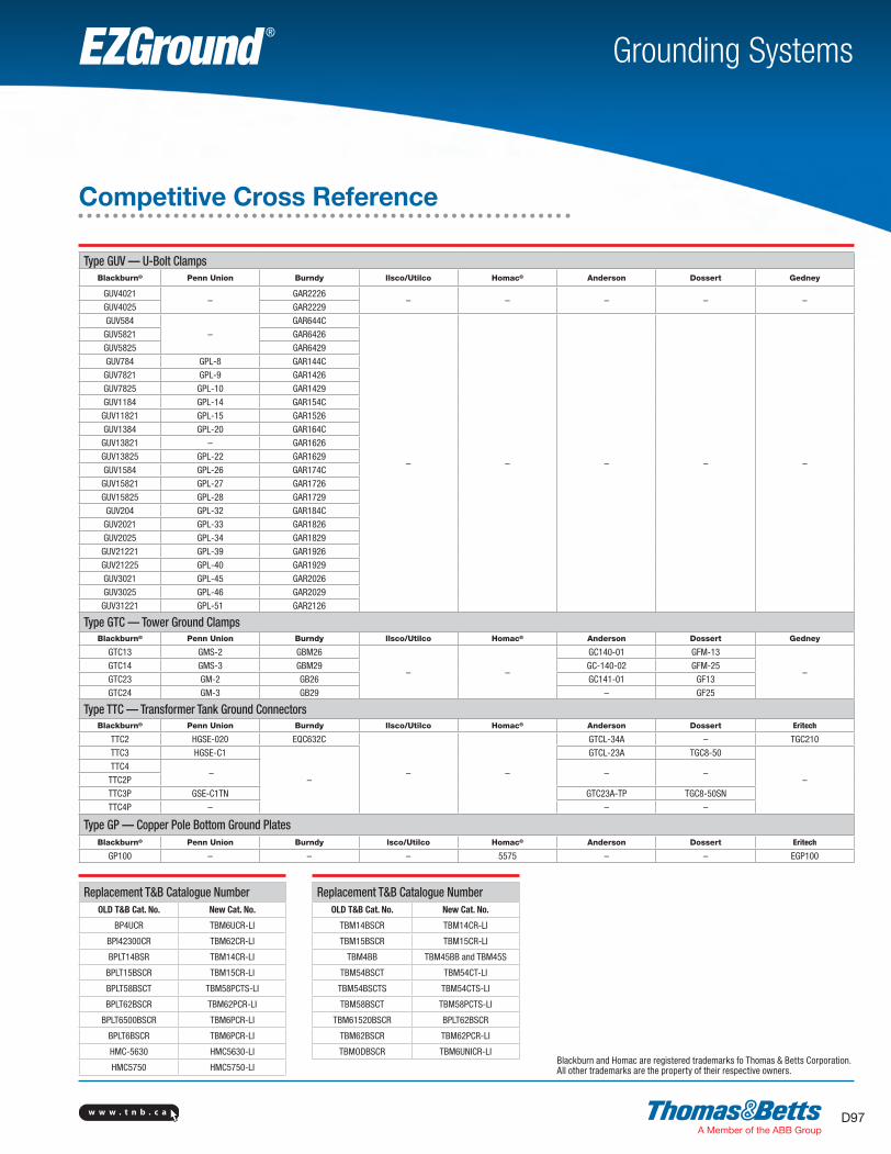
w w w . t n b . c a D97
Grounding SystemsEZGround ®
Competitive Cross Reference
Type GUV — U-Bolt ClampsBlackburn® Penn Union Burndy Ilsco/Utilco Homac® Anderson Dossert Gedney
GUV4021–
GAR2226– – – – –
GUV4025 GAR2229GUV584
–GAR644C
– – – – –
GUV5821 GAR6426GUV5825 GAR6429GUV784 GPL-8 GAR144CGUV7821 GPL-9 GAR1426GUV7825 GPL-10 GAR1429
GUV1184 GPL-14 GAR154CGUV11821 GPL-15 GAR1526GUV1384 GPL-20 GAR164C
GUV13821 – GAR1626
GUV13825 GPL-22 GAR1629
GUV1584 GPL-26 GAR174C
GUV15821 GPL-27 GAR1726
GUV15825 GPL-28 GAR1729
GUV204 GPL-32 GAR184C
GUV2021 GPL-33 GAR1826
GUV2025 GPL-34 GAR1829
GUV21221 GPL-39 GAR1926
GUV21225 GPL-40 GAR1929
GUV3021 GPL-45 GAR2026
GUV3025 GPL-46 GAR2029
GUV31221 GPL-51 GAR2126
Type GTC — Tower Ground ClampsBlackburn® Penn Union Burndy Ilsco/Utilco Homac® Anderson Dossert Gedney
GTC13 GMS-2 GBM26
– –
GC140-01 GFM-13
–GTC14 GMS-3 GBM29 GC-140-02 GFM-25
GTC23 GM-2 GB26 GC141-01 GF13
GTC24 GM-3 GB29 – GF25
Type TTC — Transformer Tank Ground ConnectorsBlackburn® Penn Union Burndy Ilsco/Utilco Homac® Anderson Dossert Eritech
TTC2 HGSE-020 EQC632C
– –
GTCL-34A – TGC210
TTC3 HGSE-C1
–
GTCL-23A TGC8-50
–TTC4
– – –TTC2P
TTC3P GSE-C1TN GTC23A-TP TGC8-50SNTTC4P – – –
Type GP — Copper Pole Bottom Ground Plates Blackburn® Penn Union Burndy lsco/Utilco Homac® Anderson Dossert Eritech
GP100 – – – 5575 – – EGP100
Blackburn and Homac are registered trademarks fo Thomas & Betts Corporation.All other trademarks are the property of their respective owners.
Replacement T&B Catalogue NumberOLD T&B Cat. No. New Cat. No.
BP4UCR TBM6UCR-LI
BPI42300CR TBM62CR-LI
BPLT14BSR TBM14CR-LI
BPLT15BSCR TBM15CR-LI
BPLT58BSCT TBM58PCTS-LI
BPLT62BSCR TBM62PCR-LI
BPLT6500BSCR TBM6PCR-LI
BPLT6BSCR TBM6PCR-LI
HMC-5630 HMC5630-LI
HMC5750 HMC5750-LI
Replacement T&B Catalogue NumberOLD T&B Cat. No. New Cat. No.
TBM14BSCR TBM14CR-LI
TBM15BSCR TBM15CR-LI
TBM4BB TBM45BB and TBM45S
TBM54BSCT TBM54CT-LI
TBM54BSCTS TBM54CTS-LI
TBM58BSCT TBM58PCTS-LI
TBM61520BSCR BPLT62BSCR
TBM62BSCR TBM62PCR-LI
TBMODBSCR TBM6UNICR-LI
SectionD-grounding-systems.indd 97 6/6/2017 9:44:18 AM

SectionD-grounding-systems.indd 98 6/6/2017 9:44:18 AM