Grounding in a GMC Motorhome - - GMC Eastern … · 1 Grounding in a GMC Motorhome •Ken Burton...
29
1 Grounding in a GMC Motorhome • Ken Burton • Electrical Engineer • Hebron, Indiana Friday, July 8, 2011
Transcript of Grounding in a GMC Motorhome - - GMC Eastern … · 1 Grounding in a GMC Motorhome •Ken Burton...
1
Grounding in a GMC Motorhome
• Ken Burton•Electrical Engineer•Hebron, Indiana
Friday, July 8, 2011
Four Functions of Ground
•Provide a safety circuit for shock prevention when connected to 120 / 240 volt shore power.
•Conduct ½ of the circuit for 12 volt DC devices.
•Provide electrical and electronic noise filtration and shielding
•Provide Radio Frequency shielding.
2
Friday, July 8, 2011

Three Grounding Systems
•1. 120 Volts AC in the house
•2. Engine-driven 12 volts DC
•3. House-driven 12 volts DC
3
• We will also cover the three (3) ground system interconnections and special considerations for the Onan, cruise control, and radio antennas
Friday, July 8, 2011
120 VAC “Green Wire” Ground
•120 volt AC ground is a safety ground.
•Prevent you from being shocked if there is a problem with one a 120 volt device or wiring inside coach.
•Primary 120 VAC item that shorts to ground in the GMC is the electric water heating element.
•Any 120 volt device can cause a problem.
4
Friday, July 8, 2011
120 VAC “Green Wire” Ground
•120 volt AC ground is provided by the connection of the “green wire” (round power pin of the power cable) DIRECTLY to the aluminum coach frame. Sometimes lead is connected through breaker panel.
•“Green wire” is never connected to the 120 volt neutral wire anywhere in the GMC.
•Green safety to neutral connection is only made at the power source. Either in the shore power system or in the Onan generator.
5
Friday, July 8, 2011
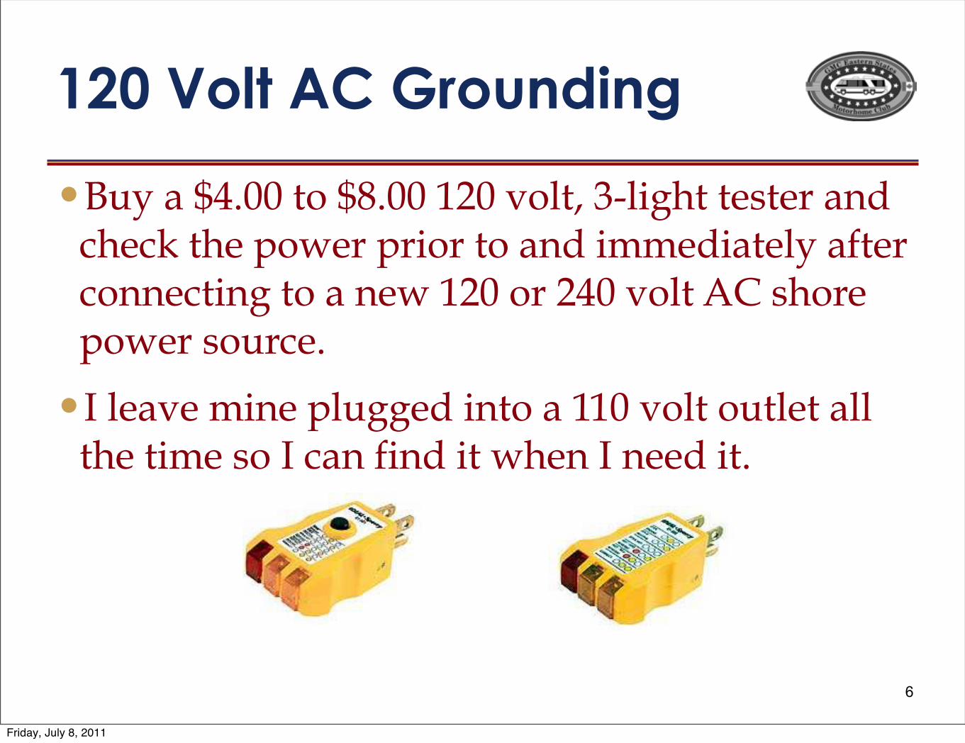
120 Volt AC Grounding
•Buy a $4.00 to $8.00 120 volt, 3-light tester and check the power prior to and immediately after connecting to a new 120 or 240 volt AC shore power source.
•I leave mine plugged into a 110 volt outlet all the time so I can find it when I need it.
6
!"#$%&'($)*$+,&-./0.1$!"#$%%&#'"'()'"*+$",$*")"-./00"'+"-1/00230"4+5'"6"57%('"'&#'&8")9:";(&;<"*+$8"=+>&82,0&,$(&")9:"0334/05(4'6$57(4,";+99&;'79%"'+")"9&>"230"+8"3.0"4+5'"?@"#(+8&"=+>&8#+$8;&/"
!"5&)4&"A79&"=5$%%&:"79"'+")"220"4+5'"+$'5&')55"'(&"'7A&"#+"!";)9"B79:"7'">(&9"!"9&&:"7'/""
Friday, July 8, 2011
12 volt DC Grounding
•In 12 volt DC systems, the ground is 1/2 of the circuit supplying power to 12 V DC accessories.
•The ground path is just as important as the electrical wires when supplying +12 volt power to the accessories.
•It is very common for ground connections to corrode or oxidize over the years causing low or missing voltage problems.
•Previous Owners are also a major problem.7
Friday, July 8, 2011
Two, 12 Volt Ground Systems
•Visualize coach body removed from frame. Result is two, separate coach pieces – the ENGINE (chassis) and the HOUSE (body).
•Each is capable of powering itself separate from the other.
•When attaching a new 12 volt device, or trouble shooting an existing one, determine which power source (ENGINE or HOUSE) you are using and use the same ground.
8
Friday, July 8, 2011

12 Volt DC Engine Ground
•MAIN GROUND for ALL 12 VDC engine-powered devices is ENGINE itself. Generally includes all devices from cockpit steps forward, plus brake, tail, and clearance lights.
•All 12 volt DC devices should have a connection back to engine on shortest path as practical.
•Engine battery negative lead is connected to engine block and not frame.
•There should NEVER be multiple ground paths to engine from any device.
9
Friday, July 8, 2011
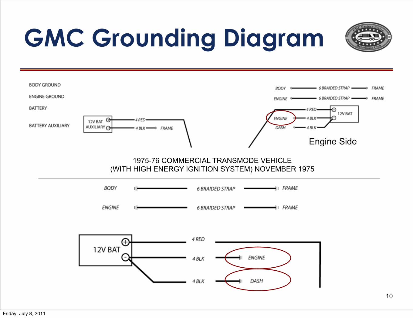
GMC Grounding Diagram
10
Engine Side
1975-76 COMMERCIAL TRANSMODE VEHICLE(WITH HIGH ENERGY IGNITION SYSTEM) NOVEMBER 1975
Friday, July 8, 2011
12 Volt House Grounding
11
•MAIN GROUND for everything in the coach aft of the cockpit steps is the ALUMINUM coach chassis. (Not the steel frame that has wheels attached to it.)
•All items powered by converter or house batteries should go on shortest practical path to aluminum body for a ground.
•Converter and house battery(s) should be connected directly to the aluminum frame.
Friday, July 8, 2011
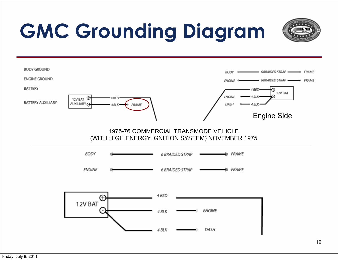
GMC Grounding Diagram
12
Engine Side
1975-76 COMMERCIAL TRANSMODE VEHICLE(WITH HIGH ENERGY IGNITION SYSTEM) NOVEMBER 1975
Friday, July 8, 2011
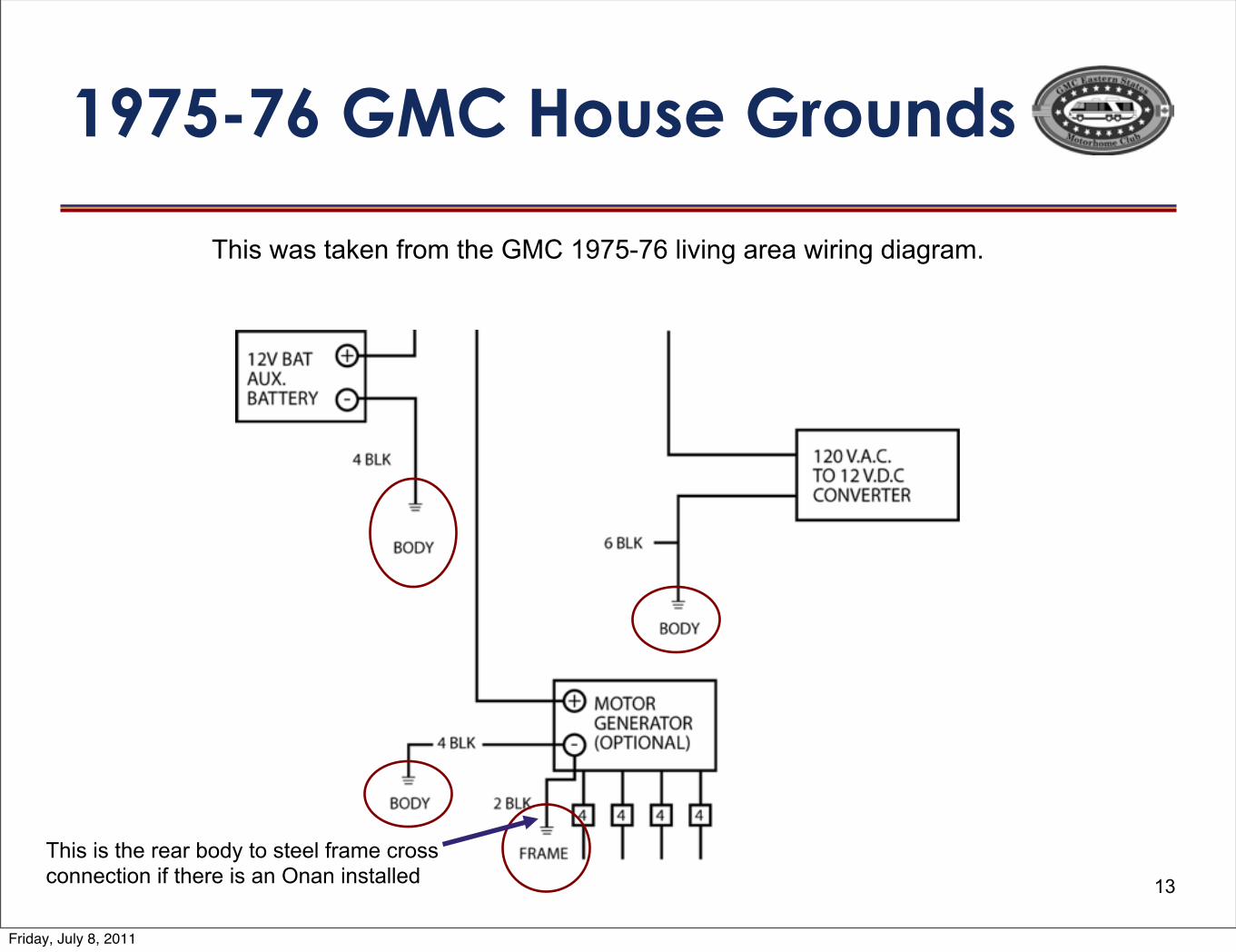
1975-76 GMC House Grounds
13
This was taken from the GMC 1975-76 living area wiring diagram.
This is the rear body to steel frame cross connection if there is an Onan installed
Friday, July 8, 2011
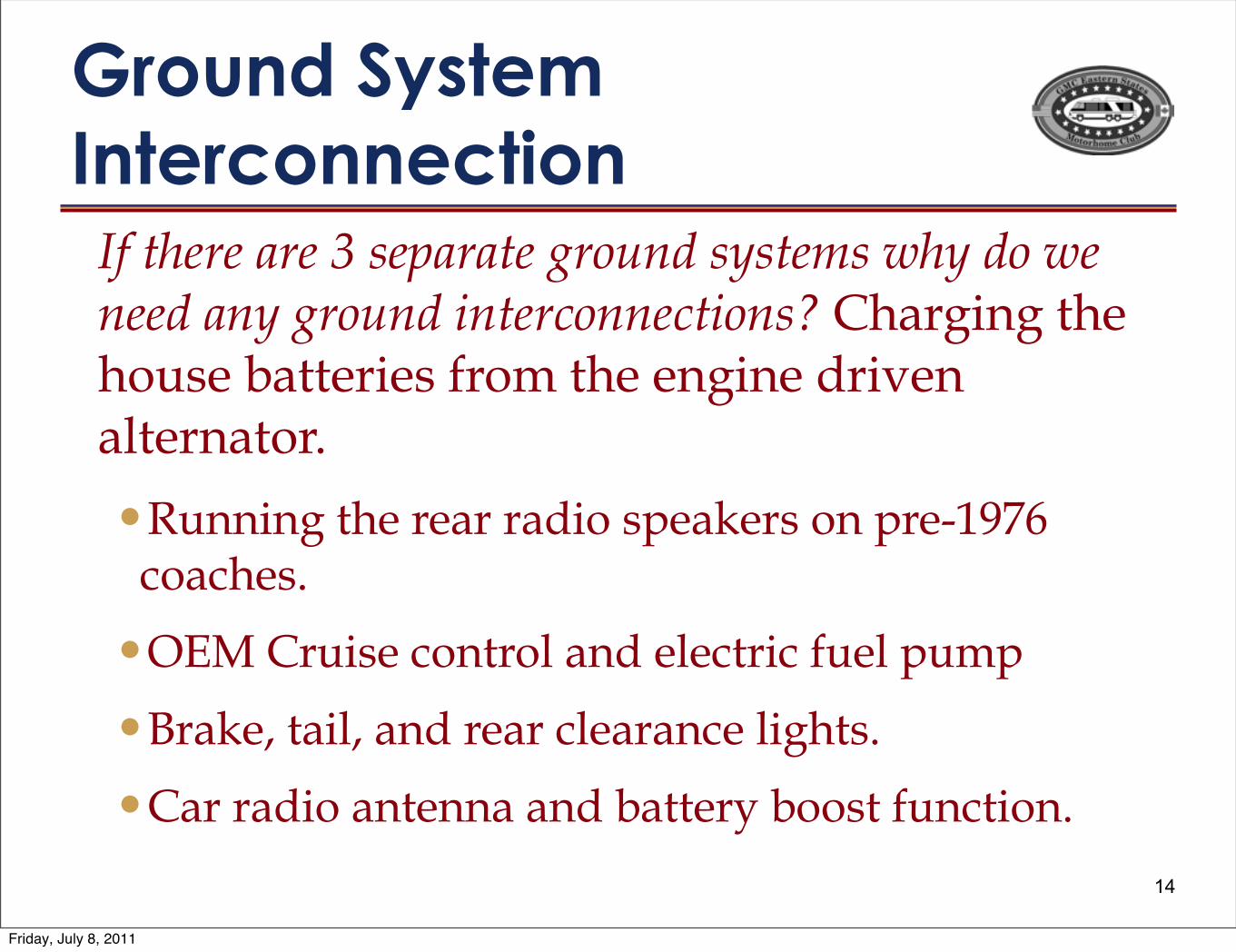
Ground System Interconnection
14
If there are 3 separate ground systems why do we need any ground interconnections? Charging the house batteries from the engine driven alternator.
•Running the rear radio speakers on pre-1976 coaches.
•OEM Cruise control and electric fuel pump
•Brake, tail, and rear clearance lights.
•Car radio antenna and battery boost function.
Friday, July 8, 2011
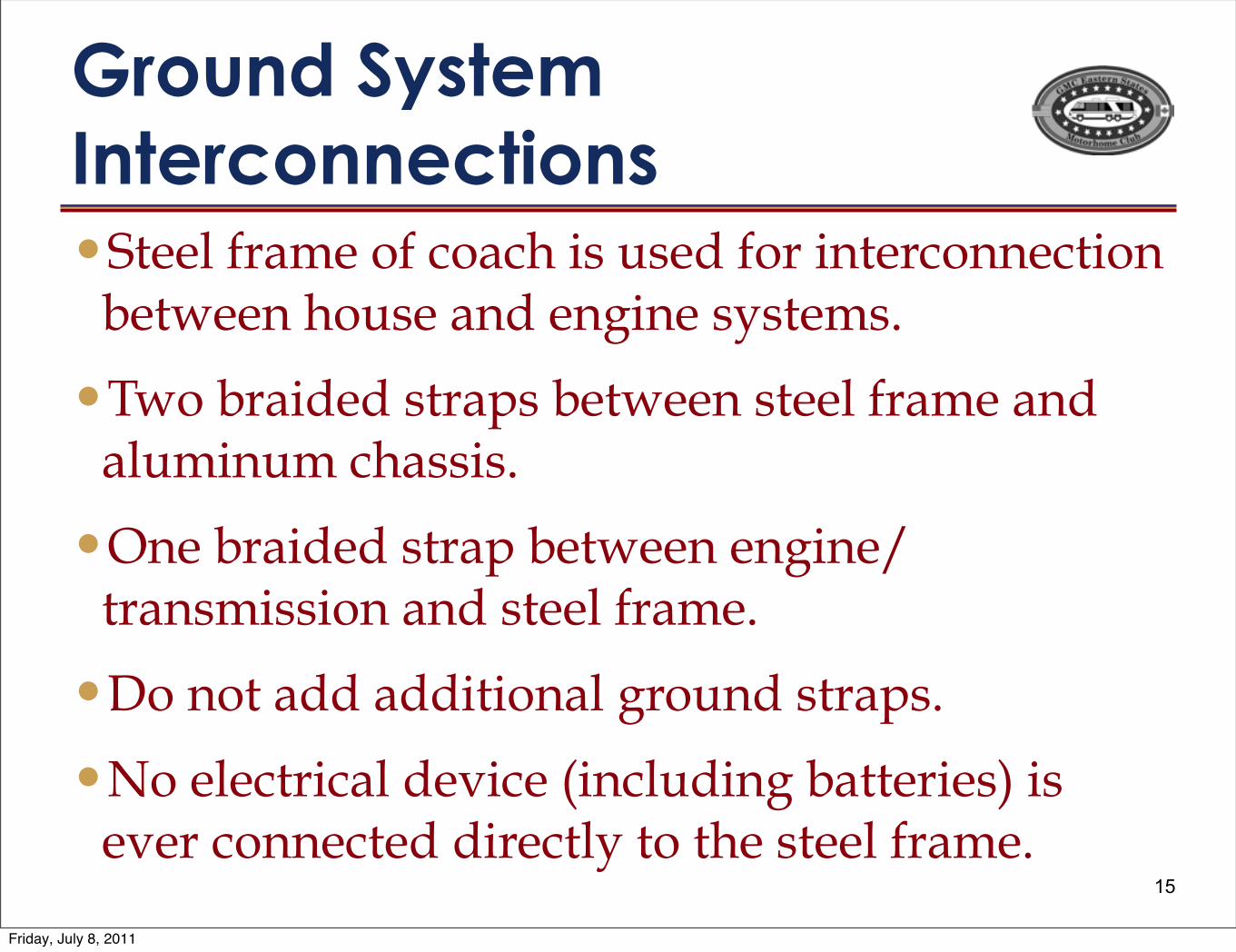
Ground System Interconnections•Steel frame of coach is used for interconnection
between house and engine systems.
•Two braided straps between steel frame and aluminum chassis.
•One braided strap between engine/transmission and steel frame.
•Do not add additional ground straps.
•No electrical device (including batteries) is ever connected directly to the steel frame.
15
Friday, July 8, 2011
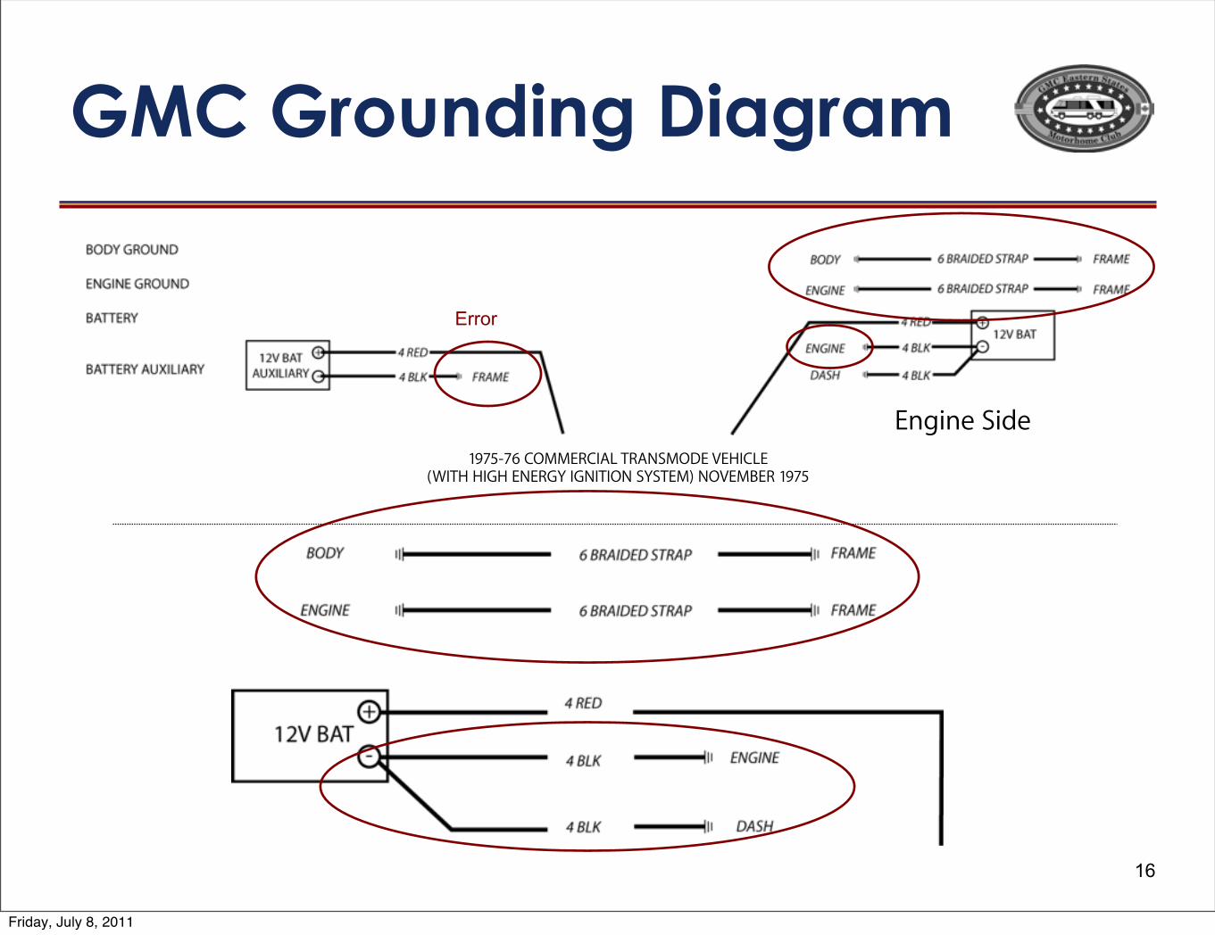
GMC Grounding Diagram
16
Engine Side1975-76 COMMERCIAL TRANSMODE VEHICLE
(WITH HIGH ENERGY IGNITION SYSTEM) NOVEMBER 1975
Error
Friday, July 8, 2011
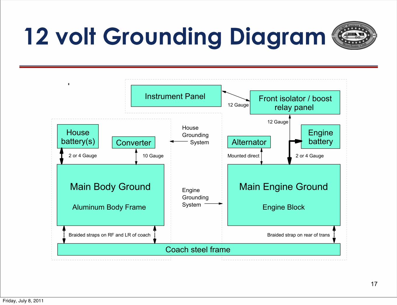
12 volt Grounding Diagram
17
!"#$%&'()%*+',$(
-.,/#$,/%&'()%0+"/1%
!"#$%2$3#$1%*+',$(
2$3#$1%&.'45
6$78+,/1$8%9"$1.%
2$3#$1%:"881+)
;'"4<%7811.%=+"/1%
>',71%:"881+)?7@
!"#$%&'#()%*+,-+.#/-0.)01
;'$A1+81+ -.81+$"8'+
0+'$8%#7'."8'+%B%:''78%+1.")%C"$1.%
&+"#(1(%78+"C7%'$%D0%"$(%ED%'=%4'"4< &+"#(1(%78+"C%'$%+1"+%'=%8+"$7
F%'+%G%*",31 F%'+%G%*",31HI%*",31
HF%*",31
HF%*",31
!',$81(%(#+148
>',71%
*+',$(#$3%
%%%%%J)781/
2$3#$1%
*+',$(#$3
J)781/
Friday, July 8, 2011
Ground Loops
A ground loop occurs when there are multiple return paths from a device to the master ground.
1.Multiple ground paths can set up a high gain antenna at random frequencies. These can radiate electrical noise throughout the coach.
2.Even worse is the possibility that electrical current can return to the power source on unexpected routes.
18
Friday, July 8, 2011
Ground Loops
•Dick P. says to run a wire direct from the base of the distributor to the battery.
•I say DO NOT DO THIS because this provides an alternate ground path to the battery.
•What would happen if the negative battery cable becomes corroded or disconnected?
•I say connect the base of the distributor to the master ground which is the engine.
19
Friday, July 8, 2011
Ground Loops
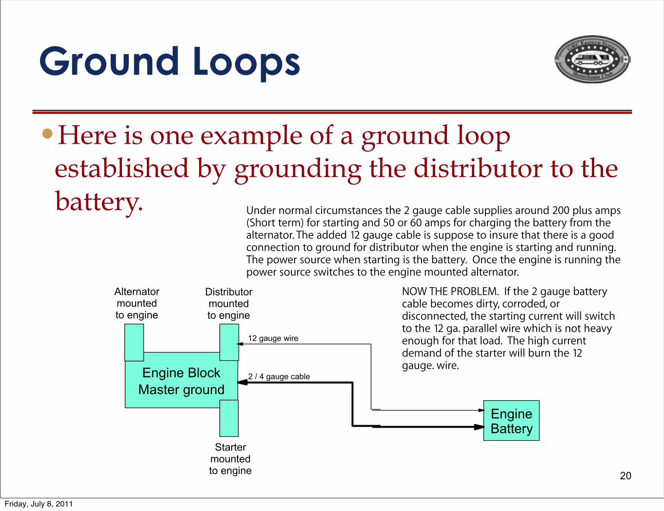
•Here is one example of a ground loop established by grounding the distributor to the battery.
20
!"#$%&'(##)*
!"#"$%&$'("$")*+,-"$'.$*$/#'0(1$-'',$"&2*3-%&4"1$
35$/#'0(1%(/$24"$1%&2#%302'#$2'$24"$3*22"#56
7(/%("$8*22"#5
7(/%("$8-'9:
;*&2"#$/#'0(1
<%&2#%302'#$+'0(2"1$
2'$"(/%("
=2*#2"#$+'0(2"1$
2'$"(/%("
>-2"#(*2'#+'0(2"1$
2'$"(/%("
?$@$A$/*0/"$9*3-"
B?$/*0/"$C%#"
D(1"#$('#+*-$9%#90+&2*(9"&$24"$?$/*0/"$9*3-"$&0,,-%"&
$*#'0(1$?EE$,-0&$*+,&$F=4'#2$2"#+G$.'#$&2*#2%(/$*(1$HE$
'#$IE$*+,&$.'#$94*#/%(/$24"$3*22"#5$.#'+$24"$*-2"#(*2'#6
J4"$*11"1$B?$/*0/"$9*3-"$%&$&0,,'&"$2'$%(&0#"$24*2$24"#"$
%&$*$/''1$9'(("92%'($2'$/#'0(1$.'#$1%&2#%302'#$C4"($24"$
"(/%("$%&$&2*#2%(/$*(1$#0((%(/6$J4"$,'C"#$&'0#9"$C4"($
&2*#2%(/$%&$24"$3*22"#56$$K(9"$24"$"(/%("$%&$#0((%(/$24"$
,'C"#$&'0#9"$&C%294"&$2'$24"$"(/%("$+'0(2"1$*-2"#(*2'#6$$$
LKM$J!7$NOK8P7;6$$Q.$24"$?$/*0/"$3*22"#5$9*3-"$3"9'+"&$
1%#25R$9'##'1"1R$'#$1%&9'(("92"1R$24"$&2*#2%(/$90##"(2$C%--$
&C%294$2'$24"$B?$/*6$,*#*--"-$C%#"$C4%94$%&$('2$4"*S5$"('0/4$
.'#$24*2$-'*16$$+,-',./,'0$""-%1'&-23%&'#4'1,-'
*13"1-"'5.66'7$"%'1,-'89'/3$/-:'5."-:
Under normal circumstances the 2 gauge cable supplies around 200 plus amps (Short term) for starting and 50 or 60 amps for charging the battery from the alternator. The added 12 gauge cable is suppose to insure that there is a good connection to ground for distributor when the engine is starting and running. The power source when starting is the battery. Once the engine is running the power source switches to the engine mounted alternator.
NOW THE PROBLEM. If the 2 gauge battery cable becomes dirty, corroded, or disconnected, the starting current will switch to the 12 ga. parallel wire which is not heavy enough for that load. The high current demand of the starter will burn the 12 gauge. wire.
Distributormountedto engine
Alternatormountedto engine
Startermountedto engine
Friday, July 8, 2011
12 volt Grounding
21
•In the GMC 12 volt DC engine and house systems, the ground is 1/2 of the circuit supplying power to 12V DC accessories.
•The ground path is just as important as the electrical wires in supplying power to all of your accessories.
•It is very common for ground connections to corrode or oxidize over the years causing low or missing voltage problems.
•Previous Owners are also a major problem.
Friday, July 8, 2011
GMC Antenna Grounding
•All vertical monopole antennas (with a few rare exceptions) require a good ground to operate properly.
•On a vertical antenna the metallic body of the vehicle is 1/2 of the total antenna.
•The antenna requires a good connection to the body (ground) at it’s base.
•Horizontal antennas, like over the air TV, which have 2 equal sections are called dipoles. These do not require a ground.
22
Friday, July 8, 2011
Radiator Grounding
23
•The radiator is mounted in rubber and is electrically insulated from the coach body, engine, and steel frame. The radiator is grounded to the ENGINE by the steel transmission cooler lines.
•Changing the lines to rubber or connecting other +12 or ground circuits to the radiator can cause electrolysis which will eat holes in the radiator.
•If you suspect a problem, measure with a voltmeter between the coolant and the radiator for voltage. Also measure between the coolant and the engine.
•Any reading over .15 volts DC or AC is a problem.
Friday, July 8, 2011
Testing for Electrolysis(Stolen from Somewhere on the Internet)
A voltmeter capable of reading both AC and DC currents is required to test cooling systems. The meter needs to read zero to the maximum voltage of the system being tested in tenths of a volt. The meter leads must be long enough to reach between the coolant (radiator filler cap) and the engine. An ohm function of a voltmeter is very helpful to pinpoint areas of resistance in as electrical system that will cause an electrical current to ground through the coolant rather than the engineered electrical circuit. • Procedure
• With the digital voltmeter set to 20 volts or above, attach the negative meter lead to the engine. • Install the second lead in the coolant touching the coolant only by reaching through the radiator fill. • Read the DC and AC voltage with all systems off. If a block heater is present, also take a reading with the heater turned
on. If an automatic battery charger is present, as a standby system, also take a reading with this system running. • Read the DC and AC voltage with the electrical starter engaged. • Read the DC and the AC voltage with the engine running and all systems turned on: lights, coolers, fans, heaters, air
conditioning, cell phone, two-way radio, including the phone and radio on both standby and transmit. • Voltage of zero to .3 is normal in the coolant of a cast iron engine. Such an engine will be destroyed with time by .5 volts,
and engine manufactures are reporting .15 volts will destroy an aluminum engine. • The current / voltage will be AC if the problem is due to static electricity. • If the coolant shows an electrical problem with all the equipment turned on; turn off one system at a time until you finally
turn off the system that stops the electrical current. When the current stops, this will indicate the electrical system causing the problem.
• Be partially careful of starters. They can cause as much damage to a cooling system as a direct connection to an arc welder. This is due to the amperage present.
• Always change the coolant if a current is detected. The electrical current will destroy the protecting chemicals in a properly inhibited coolant.
24
Friday, July 8, 2011

25
Diagnosing Bad Grounds
• You will Need a inexpensive VOM (Volt Ohm Meter)
• These are available from many sources:
• Harbor Freight has a cheap one that ranges from $2.99 to $7.99http://www.harborfreight.com/7-function-multimeter-98025.html
• I like the Sears one because it can also read frequency to set the Onan speed.http://www.sears.com/shc/s/p_10153_12605_03482139000P?mv=rr
25
Friday, July 8, 2011
Diagnosing Bad Grounds
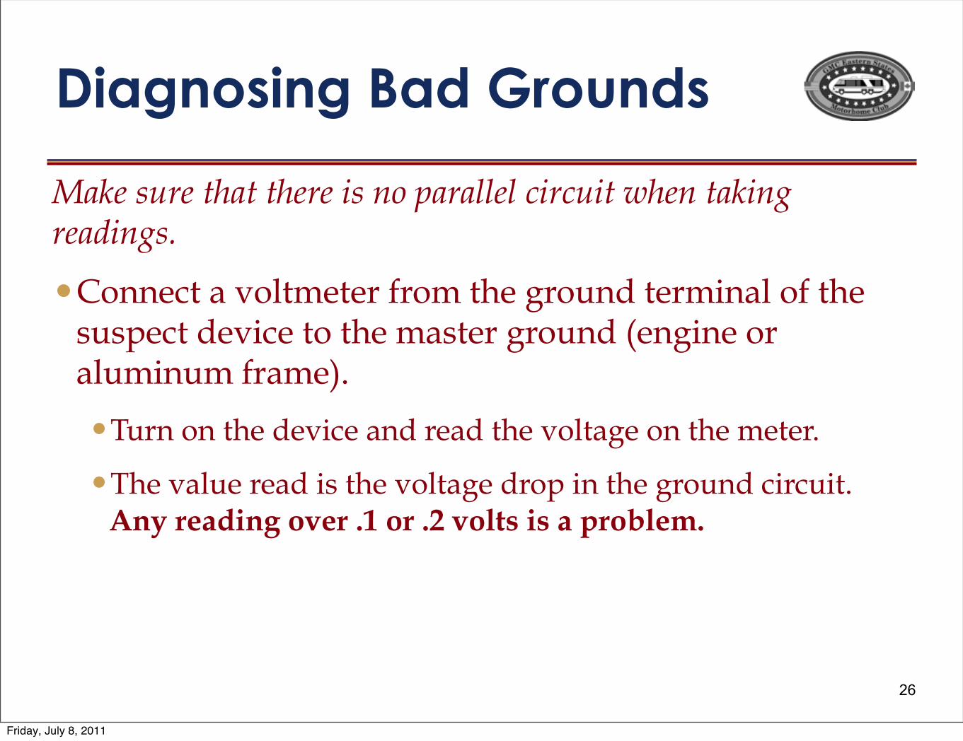
Make sure that there is no parallel circuit when taking readings.
•Connect a voltmeter from the ground terminal of the suspect device to the master ground (engine or aluminum frame).
•Turn on the device and read the voltage on the meter.
•The value read is the voltage drop in the ground circuit.Any reading over .1 or .2 volts is a problem.
26
Friday, July 8, 2011
Diagnosing Bad Grounds
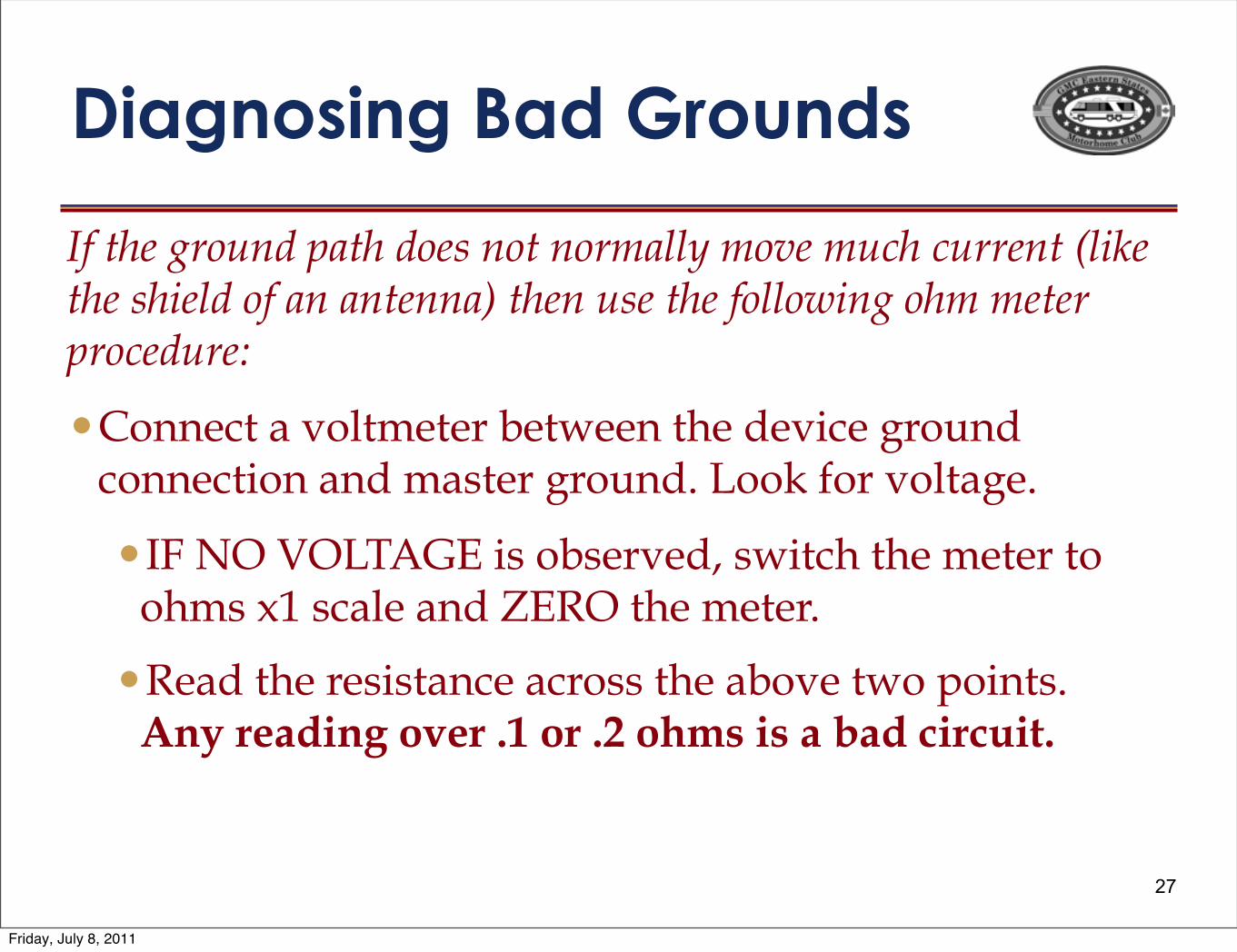
If the ground path does not normally move much current (like the shield of an antenna) then use the following ohm meter procedure:
•Connect a voltmeter between the device ground connection and master ground. Look for voltage.
•IF NO VOLTAGE is observed, switch the meter to ohms x1 scale and ZERO the meter.
•Read the resistance across the above two points.Any reading over .1 or .2 ohms is a bad circuit.
27
Friday, July 8, 2011

Fixing Bad Ground Connections•Disassemble and CLEAN, CLEAN, CLEAN
ALL connection components until they are SHINY.
•Use star or tooth washers between the terminals and the item being grounded.
•Use anti-oxidation grease on all connections to prevent or retard new oxidation/corrosion.Anti-oxidation grease is available at Menards, Lowes, or Home Depot in the electrical department
28
Friday, July 8, 2011
Summary
• There are 3 GMC ground systems. Treat each of them as an independent system.
• The 120 volt “Green Wire” Ground connects direct to the coach body.• The 120 volt “Green Wire” Ground and NEUTRAL are NOT CONNECTED
together anywhere inside the GMC.• The master ground for engine powered devices is the ENGINE.• The engine battery negative cable connects direct to the engine.• The master ground for house powered devices is the ALUMINUM BODY.• The house battery(s) negative cable connects to the ALUMINUM BODY.• Clean and grease any suspect connection even if it looks good.• An improperly grounded radiator will get holes from Electrolysis.• Do NOT run multiple or parallel ground paths.• Never attach any electrical device to the steel frame.• Vertical antennas require a good ground connection at their base.• Never trust that a PO did it correctly.
29
Friday, July 8, 2011