GROUND WATER By Thad G. Mclaughlin North Dakota Ground ...
28
GROUND WATER AT DICKINSON, NORTH DAKOTA B y Thad G . Mclaughli n with a section on geology by A . L . Greenle e North Dakota Ground Water Studies No . 3 Prepared in Cooperation with the North Dakot a Geological Survey, the North Dakota Stat e Department of Health and the City of Dickinson , North Dakot a October, 1946 Printed Through the Courtesy of the State Water Conservation Commission
Transcript of GROUND WATER By Thad G. Mclaughlin North Dakota Ground ...
GROUND WATER
AT DICKINSON, NORTH DAKOTA
By
Thad G. Mclaughlin
with a section on geology by
A. L . Greenlee
North Dakota Ground Water Studies No . 3
Prepared in Cooperation with the North Dakot aGeological Survey, the North Dakota StateDepartment of Health and the City of Dickinson ,
North Dakota
October, 1946
Printed Through the Courtesy of the State Water Conservation Commission

C O N T E N T SPage
Abstract • 1
Introduction 1
General information 2
History of the water supply 2
Geology of the Dickinson area 4
Potential water producing aquifers in the Dickinson area
---- 10
Physical properties of water bearing materials 1 1
Definitions and general considerations 1 1
Behavior of the water level near a pumped well 12
Pumping tests 13
Schedule of operations 13
Determination of transmissibility 13
Determination of specific yield 15
Quantity of ground water 15
Yield of municipal wells 15
Determination of steady state drawdown 15
Conclusions 16
Well logs . 17
----------------------------------------- -Well schedules 18
References 21
ILLUSTRATIONS
Fig . 1 - Map of a part of the City of Dickinson showing th e
Fig . 2]location of municipal wells
- Cross section of Dickinson well field AttachedAttached
Fig . 3 - Graph of data from pumping test of well 3 AttachedFig . 4 - Time drawdown graph for test of well 3 Attached
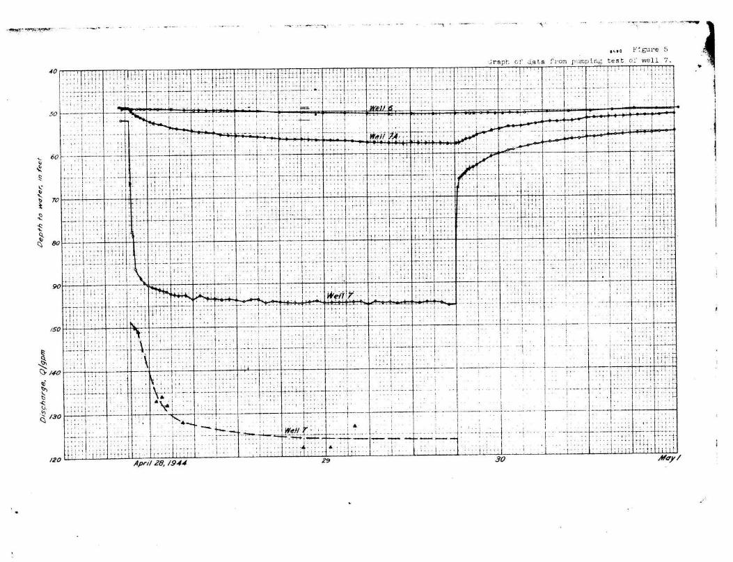
Fig . 5 - Graph of data from pumping test of well 7 Attached
Fig . 6 - Time drawdown graph for test of well 7 Attached
ABSTRACT
The City of . D'icki.neon, North Dakota,- dependslargely upon . ground water for itsmunicipal afd industrial needs . The wells are at present located ' in a singlewell field within an''area about one mile by one-half mile, and they all drawftom the same aquifer, Normal - growth and industrial development increased maxi -mum daily' pumpags from about 300,000 gallons in 1937 ` to • about 550,000 gallon sin 1944 . This investigation ' had as its purpose the-defining of the area ofinfluence of the existing wells and the determination-of . the capacity . of theaquifer to transmit additional quantities of water . It was the intention o fthe City to drill. additional wells in the present well field if they wer ewarranted ,
The financial limits' -of the cooperation did notpermit .extensive test-drillingfor locating additional well fields at some distance nor did they permit deepdrilling .to test additional aquifers at depth .
The existing well field is being depleted at the present rate of .pumping. . Thetranemisaibilityi or capacity of the aquifer to transmit water, : is relativelylow. Approximately 80 feet of'aquifer have been permanently unwatered in theeast end of the field. Conclusions of this investigation indicate that addi-tional wells in the sane bed in this vicinity are not justifiable and woul donly tend to deplete the present supply more rapidly . Other recommendationsare based on an analysis of previous reports and records of earlier test drill-ing and-a study-Of - the geology of the area .
INTRODUCTION
Ground water levels in the municipal well field at Dickinson have declinedrapidly in recent years, resulting in increased pumping lifts and decreasedyields . During the summer of 1943 the demand for water exceeded the capacit yof the wells, making it neceasary .to restrict the use of water . In the-springof 1944 the'city-planned to-drill, test wells in the field in order tochoose .asite for an additional'aupply'well . In March 1944 the city council requeste dthe cooperation of theNorth , Dakota State Department of Health In conducting aquantitative study of 'ground'water resource . of the area. The Health Departmentpresented the problem t:o the State Geologist who suggestedthat a-cooperativestudy with the Federal'Survey be arranged . The work was done by the'United StatesGeological Survey cooperating with the North Dakota-State`Department of Healththrough the office of the State Geologist, and with the : City of Dickinson. Theinvestigation was; made under the direction of A . L. Greenlee, federal geologis tin charge of ground water investigations in North Dakota and K. C. Lauster,acting director of the Division of Sanitary Engineering of the North Dakot aState Department of Health .
The field work was done during the period from March 27 to May 6, . 1944, Twotest holes (3B and 7A on fig . 1*) were drilled for the city by the McCarthyWell Company in order to . determine the thickness and character of the water*bearing material8And to measure' the fluctuatiods Of the water levels duringpumping tests . Levels were run to all of the wells and test holes, and pumpingtests were made of well 3 in the eastern part of the well field and well 7 atthe western end of the well field .
*w*Figure 1 - Map of a part of the City of Dickinson showing the location of themunicipal wells .
1 .
W. L . Littlehales, city water superiatendeet, supplied data on the. ,municipalwells and assisted in ' the'conduction of the pumping tests . . A. L. Greenleevisited the area of investigation, several times and assiste d . in . planning thefield work and in making computation's . The report wasreviewed critically by0 . E. Meinzer, S . W. Lohman,' V. (. Fichel, and C. E . Jacob of the'gederalGeological Survey, and by K . G. Laminar of the North Dakota State Departmentof Health . Most of. the calculations were made by C . S. Jacob .
GENERAL INFORMATION
The well, field at . Dickinson -is located 'in the northern, .part. of the, city . in theNk sec . 4,' and the NWT sac . .3 ; T . 139-N., R. 96 W . (fig., I) ..; , The area of thewell field is divided approximately, in half by, a. long,narrow .hill that trends.northward . (fig . 2*) . The eastern half of the field was the first to b edeveloped. and-at the time of the investigation it 'had four. wells,.,,0ne well(no . 4) is equipped with a double. acting cylinder pump powered .by, a 15 horsepower oil engine .' The-other wells'(nos . 1, 2 and 3)-are gravel , walled wells .equipped with : turbine . pumps that are powered by electric motors . : Water fromthese wells is discharged into concrete . catch basins and then-flowsby,gravityto a'concrete-cistern of about '200,000 gallons capacity which is located nearthe-pump station . From the cistern, the water can be pumped , . directly into themains or into a steel reservoir of 849,000'gallons eapacity :which is,locatedat the crest of the hill that transacts the well field . Wells 1, 2, 3 and 4range in depth from about 170 feet to 196 feet below land surface. In April1944 the altitude of the static watwlevel-in the wells ranged from 179 .55 to201.20 feet above the assumed datum . The depths to water level below themeasuring points ranged from .97 .72 feet'in well. 4 to .132 .05 feet :in :well 3(fig . 2) .
There are three wells in the western half of the municipal well field (nos .5, 6, and 7 on fig . 1) . Each iia gravel-wailed well and . is equipped witha turbine pump powered by a 20 horsepower electricmotar . Water from thesewells is discharged into a 6 inch pipeline and is pumped eastward over thehill by the turbine pumps . At a point near well , 3the water enters a con- .crate . catch basin and then flows"by .gravity to .the concrete cistern near .thepump station ., . Wells . 5,. .6, and' 7 range in depth from-135 to 155 feet belowland surface . .The .altitudes above assumed datum of•the water levels in wells5, 6, and 7 on Nay .5; 1944 were 218 .23, 261 .65, .and 262 .30 feet, respectively .
HISTORY OP THE WATER .SUPPLY
Before the construction of municipal water works the residents of Dickinso nobtained water from siany 'shallow dug wells . -A few :wells in the • higher :parts .of the city, however, were more than 50 feet deep . .The water table was notfar below ground in the southern part 'of the town, adjacent to the Heart River ,until sewers and drainage ditches were constructed . : .Thereafter .the mater tabledeclined several feet .
.
*Fig . 2 - Cross section of Dickinson well field
2 .

During the installation of the municipal water system a well was drilled at thesiteof' .the .present city hall . to rq ddepth of about 1,200 foet in an attempt t oobtain an i4eQuatesupply of_potab a ground„water,,'A moderately large quantityofwater .,was' reported .encountered ; alt tt,"depth .of 'about 300 feet but the qualityof ,the water was unsatisfactory . Provlqua attempts by the ..,NOrtbern pacificRailway Company to obtain ground water 'of satisfactory quality it' 'great depthshad been unsuccessful .
The failure of the deep well at the site of the city hall to yield an adequatequantity of potable ground water iedto the ; coustruction of a bored well in th eeastern half of the present well field, about 150 feet northwest of the presen twell 3, The we1i$ . .was;,bo d .; to .a . depth of abov t ., 130 feet . It encountered rela-tively hard bet potable rater .
•.
S Inca , thee, f J.f„at: bored' wsl~ tae pu d , im the pr,,~ ►s`ent"Mali field more than : 40test , 1 pies :and ;wells. hrnv4 beend_ bored or 'drilled by . t • Wety Lit order so! maintainan•.'edeep t supply of 114*. T t ex
loc0tion of all these test bolas is` notavmiiab ,p slt gh. it l re► rted that' t ► . were drilled within the present citylimits . :well field ely one-third of the tenting vet doeta within or near thepresent well field area . Many of the earlier test wells were less than 100~fee tin depth.
A-well teported, +about 200 feet in depth .drtne
ttat the site of the now abandoned
flour• mill located, on the. bank of the . art River about 3/4 mile 'southarest of thepresentwproud ..road quats for the neee¢s ~of; ;the mill, . It was reportedas havi404%
:;!::ma
iicapacity . of : ,about 50 gallons .p
er' minute .
Farm. wells in the vicioity usually ,are dug br bored wells about 25 to '45 feetin .depth. They pxove do,quate for # zm s4d hquuse old needs. Shallow wellswithin or. :msxt tt) thw .city limits ere repoTted~to t_t*ie i gone dry during 'the ,droughtyears: of 1933-37 and ,-have . been' abandons wit : very fever exceptions .
Sufficiently coarse sands judged suitable for development were located only, inthe vicinity of the existing well field . The more receat'wells'were drilled t oa depth of approximately 200 feet in order to penetrate all the water-bearingmaterials containing water of suitable quality .
The firm of Burns and McDonnel, consulting engineers, made a study of theDickinson water system in 1927, after which they recommended the constructionof three gravel nwalled wells in the eastern part of the well field . These wereconstructed between 1928 and 1930 and are designated as wells 1, 2, and 3(fig . 1) . At the time of the construction of these wells the water table haddeclined from a probable original altitude of about 265 feet above the assumeddatum or 42 feet below ground to an altitude of 223 feet, or 87 feet below groundat well 3 and to an altitude of 227 feet at well 1 . The altitudes of the waterlevels in wells 1 and 3 in April 1944 were 195 .4 and 179 .6 feet, or 105 feetand 129 feet respectively below ground . The average total decline of water levelin the eastern half of the well field has been about 80 feet .
The increased pumping lifts resulting from declining water levels had decreasedthe yields of the wells so that by 1934 the quantity of water available was jus tadequate for the City's needs . In order to prevent water shortages that migh tresult from the failure of wells or break-down of pumps, test drilling was begun

on the vest aide of the hill . . The test drilling resulted in the construction
of well S in 1937 (fig . 1) . More test drilling was 'done in 1938, and in . 1939wells 6 and 7 were constructed . The water table in the vicinity of wells 6 and
7 declined about 19 feet between 1939 and May 1944 :
GEOLOGY OF THE DICKINSON AREA
A. L. Greenlee
A large part of the geology of the Missouri Slope Region o f :'North Dakota, which
includes the Dickinson area, remains to be worked out . There-is . still some
divergence of view regarding the relationships of beds originally referred b y
A. G. Leonard 1/ to the Fort Union and,. Lance formations. More recent studie s
by Virginia Kline, ' 2/ 0.4. Seager et. , al ., 3/ Wilson M. Laird, 4/ and W. T.Thom, Jr., S/ supply additional data ' for further classification . The follow»
ing table gives a probable; correlation of the formations described by Leonard .
with those of more recent authors .
1/ Leonard, A . C . The geology of southwestern North Dakota with special refer -
ence to coal : North Dakota Geol . Survey, 5th Bienn. Rept ., pp . 51.64, 1908 .
2/ Kline, Virginia, Stratigraphy of North Dakota : Am. Assoc . Petroleum
Geologists Bull ., vol . 26 (no . 3), pp . 336-79, 1942 .3/ Seeger, O . A., et al ., Stratigraphy of North Dakota : Am. Assoc . Petroleum
Geologists Bull ., vol. 26 (no. 8), pp. 1414»1423, 1942 .A/ Laird, Wilson M ., Stratigraphy and' structure of North Dakota : Nat'l . Oil
Scouts and Landmen's Assoc . Year Book, vol . XIV, pp . 420430, 1944.5/ Thom, W . T ., Jr . and Dobbin, C . E., Stratigraphy of the Cretaceous-Eocene
transition beds in eastern Montana and Dakota : Geol . Soc . America Bull . ,
Vol . 35, pp ., 481-506, 1924 .
4.

' A. < G. Leonar. d .
MLC►brara 200-250' gray shale
and carrot rock
gentgn S0Q-1000' dark graysheiaaDakota 15-90'' micaceous whitesandstone-,with pyrite, gypsum
.0 ;ligr+ite
0 A. Seaga* W. M. Laird and others
' Unnamed Fa. 100' light=coloredclay ash,' sandstoneSentinel Butte . P7n. ,550' . .dark•coiored - clay,, :bsntonite ,silicified it apps
Tengye. ,;giver Pa . .30Q 1ightcoloredcalcsrewis . shale and-sandstone , and lignite.
Cannonball"Ludlow lei. 0.300 'iasrins sands, clays, Ludlow0450' lignite, ' Shale andsandstone
Bell Creek Pm.: 10b-.575' graybentonitic sandstone ,and shale ,lignltic steal ' and" concretions
Pox Hills 180.31"0' brown togray . sandstone with ironstoneconcretions
Purrs'= PM 930.2390' gray ohand-ironstone concretion s
4
White Aivsr !b' '
tipper . Fort union,= 500. hark gray
shsia sad sand-. stope .'and hg,nits
Middle Fort • Unio n500' . buff - and- . .light gray - shal eand- sandstone .Thin' beds . of • ,
Lignite .
icier Port Union'600" dinod~btr~Jbaatfiig 'sdi Wdr bD: $k 'gtay-ttirchat ssi . `ind Lignite '
: .Fox,lia .
MTV,.
Niobrara
Dakota
5 .

There are no sediments belonging to the White River formation, of Oligocene age ,in the immediate vicinity of Dickinson . Soft dark gray sandstones and shale sdescribed by Leonard as Upper Fort Union, and later named the Sentinel Butt eformation of Eocene age, are exposed at the surface and along the banks of theHeart River . Samples taken from test holes drilled in the present well fieldmay be correlated favorably with the exposures described by Leonard in the "bad-land" area about 35 miles west of Dickinson . Leonard's description is as follows :"The Fort Union is readily separated into three divisions by a marked differencein character and appearance. The upper beds are composed of rather dark graysandstones and shales, with many brown, ferruginous sandy nodules and concretions .The middle division is formed of light ash-gray and buff shales and sandstone swhich are remarkably uniform in color and appearance over extensive areas . Thelower member has a dark and somber aspect in striking contrast to the lightcolored beds above . It is composed of alternating layers of dark gray and brownshales and sandstones, conti ning many sandy nodules . The lower portion . con..tains no workable beds of coal," A little later he adds, "The top of the For tUnion is formed of a rather hard sandstone 80 to 100 feet thick ." 6/ A typica lsection of the upper Fort Union as found in Sentinel Butte and described b yLeonard follows :
Feet InchesSandstone, gray, hard • 80Shale, sandy, gray and yellow 30Shale, brown, with thin seam of coal 1 6Shale, sandy, gray and yellow 53
Coal sSandstone, fine-grained, clayey 12Shale, brown and gray, containing many selenit e
crystals 4Sandstone, soft, fine-grained 1
Coal 12-18Shala, brown and carbonaceous 1Shale,, bluish gray 10Sandstone, gray 12Shale, and sandstone, not well exposed 55
Coal 2.6Shale, sandy, gray 37Shale, gray, with no sand r 2
Coal 6Shale, sandy, brown at the top 5Sandstone, fine, gray 4Shale, sandy, gray, containing nodules 15Sandstone, finely laminated 4Shale, sandy, gray, With ferruginous bands 8Shale, sandy, brown . : 1Shale, gray 5Shale, gray, sandy, containing abundant siliceou s
and ferruginous nodule's, arranged mostly . inbands at certain horizons ; those hard nodulesproject from the surface of softer shale andcap small clay columns 25
Sandstone and•s'hale,not well exposed 25Coal 21
Unexposed to level of railroad at station of190Sentinel Butte
610 2
Op . Cit ., p . 235
6 .
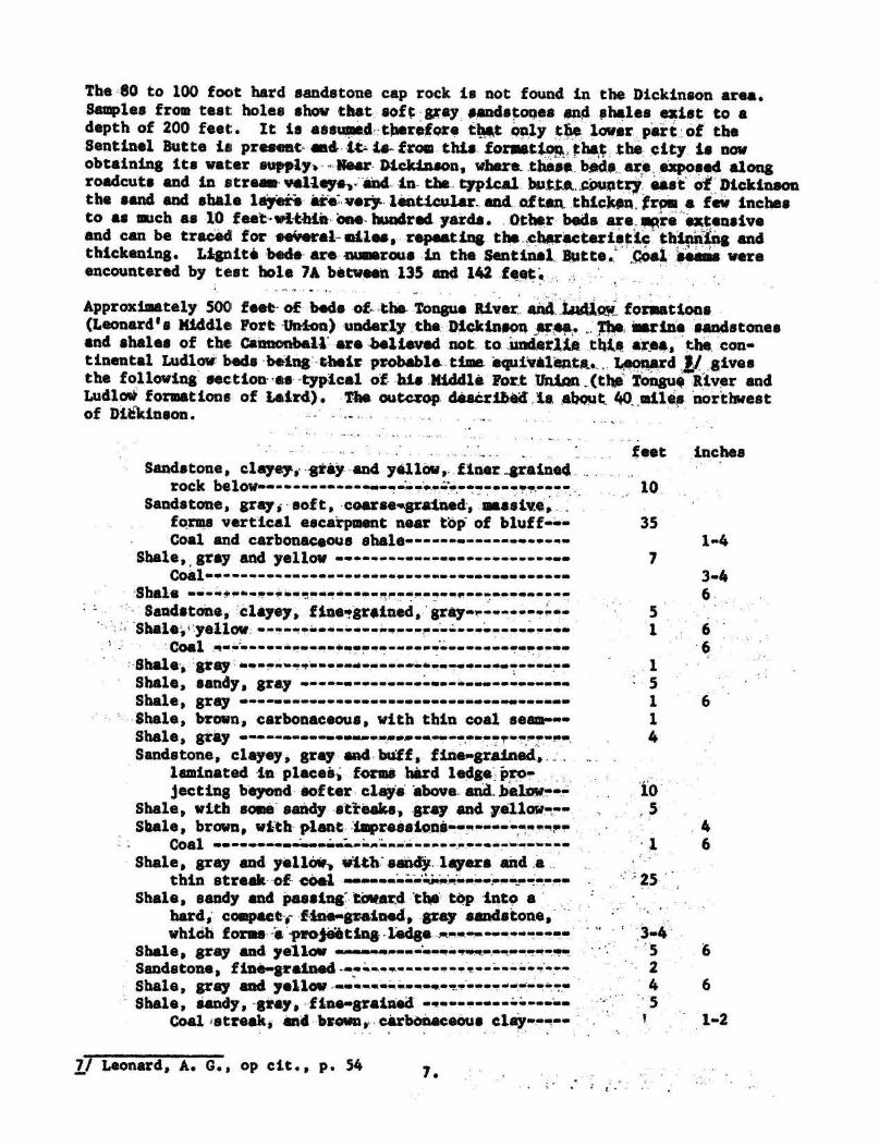
The 80 to 100 foot hard sandstone cap rock is not found in the Dickinson area .Samples from test: holes show that soft gray sandstones and shales exist to adepth of 200 feet : . It is assumed therefore that only the lower part of theSentinel Butte is present and it - 1a- from . this . formatiognw that the city. is nowobtaining its water supply . -Near- Dickinson, where_ these beds ... are. exposed alongroadcuts and in street valleyeyµ and--in- the typical but ,. .country east of Dickinsonthe sand and shale layette are very, lenticular_ and of ten, thicken, trod a few inchesto as much as 10 feet within one hundred yards. Other beds are_opRre extensiv eand can be traced for eeveral miles, repeating the _ characteristicthig andthickening . Lignite bade are numerous in the Sentinel . Butte .. Coal seams wereencountered by test hole 7A between 135 and 142 feet
. Approximately 500 feet• of beds of the Tongue Riverand. ,ludlow_ formations(Leonard's Middle Fort Union) underly the Dickinson area . . : The Marine sandstonesand shales of the: Cannonball' are believed not to ,underlie this are*, the, con-tinental Ludlow beds being -their probable time equivalents .. , Leonard 1give sthe following section- es -typical of his Middle Fort Unite ,.(thee Tongue River andLudlow formations of Laiird) . The outcrop described : is about; 40 ,miles northwestof Ditkinson
Sandstone, clayey, gray and yellow, . finer._grained . •rock below. rear-_,:. ;:..----•--•
Sandstone, gray, 'soft, -coarse•.grained•, massive .forms vertical escarpment near top of bluffCoal and carbonaceous shale
Shale, gray and yellowCoal ---- . ar_r•--_-r---r
Shale --- ..i } ►a-! a-r. *-r ..-arr-- ..
Sandstone, clayey, fine grained, grayw,.---.r--..s.Shale iyellow--ass_s_•-*---•
Coal !T-a._-r_a-_r---•••s r-- -rase3-si
Shale•,- gray •- ar.r 4.rra r -a.is-rr--aisr-see-era are reShale, sandy, gray Shale, gray -r--• • •Shale, brown, carbonaceous, with thin coal seam-• •Shales gray e ..war,. .A. *----
feet inches
10 ,
351-4
73-46
Sandstone, clayey, gray and buff,fine»grained, .laminated in places, forms hard ledge pro
1
3-4
jecting beyond softer clay. above. and, below--Shale, with some sandy st"reak s ., -gray and yellow--Shale, brown, with plant iaapreSeione-rear-e~e.e. .e
Coal -e-see..e•_..•e:...:,a :.. .-, . . .. ..
Shale, gray and yellow-, i4b. seed . layers and .athin streak -of cOel
eaii., ..r.w.►a ..•ee -Shale, sandy and passing" toward the top into a
hard, compact ; fine•grained, gray sandstone ,which forms µa, progeat
-ledge . '* 3recceShale, gray and yellow a ...ea.. ..sa-eesr-..g.. .ofir.. .44 5Sandstone, fine-grained
----.
-•--- .---..- 2Shale, gray and yellow ..•e.. .-:,;.e--+.---- 4 6Shale, sandy, -gray, -fine•graiued
..' 5
Coal streak, and brown,. carbonaceous clay-:-- .1-2
7/ Leonard, A . G., op cit ., p . 54
7 .

Feet
Inches
Sandstone and sandy clay, gray, in places th esand is cemented into hard rock, forming
a projecting ledge . ----Shale,
- -
gray . ►.rr.-ar r r .~ . .Y.r.Shale, brown Y..a « n•.a ,.-•.----
Coal r..r...r.rr ...w..ns wr r rw...
Shale, gray and yellow •• •-•--.,..rr..r r.rShale, brown, carbonaceous w.r.r rr.
Coal •
r--rr. .-r r.rrw.w-.rY.r.r.Shale, brown, with abundant plant remains ,
mostly-stem impressions -- :_..i..
1
Shale, gray --•--.►..ar•.r ae....-rr.i...
3
Sandstone, f ine-grained and sandy shale• ---
16Shale •----•-- _-• . ...a.. ..a « a
4
Shale, sandy w.
.---•ne --a.-.•-_a 6
Shale, gray 1Coal ..a . ...r-r --
Shale - rr.w r w.a.r rCoal -- - •- •- 8
Shale • r• rCoal -- re.. ..» :.r...a.r-
Shale and sandstone, not well exposed, toriver • . . .,:---- •--. ►---- ------a
40
251 -
6
The Hell Creek formation (or lower . Fort Union of Leonard) should be present inthe Dickinson area at considerable depth . This formation .is below :thestreamlevel of the Little Missouri River in the area'of badlands around Medora bu tcrops out along the east elope of the Baker anticline south Of Marmarth whic his about 75 miles southwest of Dickinson .-The beds are described by Leonard 8 /as follows :
Peet
InchesBurnt clay bed, capping the buttes ••-e • -2 6Clay, gray a- 2Sandstone, fine-grained, buff =•---- 8
9Shale, gray . . . .. . . . .. ..... . . . .. . . . . ... .. . ...
2
9
Shale, light buff 9Shale, chocolate brown, carbonaceous =r 2
Coal, impure and dirty r----
- 1 1Shale, brown -------------w.. 9
Coal, impure - -----
8Sandstone and shale, chocolate brown, carbo-
naceous -r : 2Sandstone, gray --- :.__e: 12Shale, gray ------- . 2
Shale, brown, carbonaceous 4
3Coal, impure ra a_.r .
8Sandstone, fine-grained, gray --=-~ .. . .. . ---
15
6Shale, chocolate brown . ... .. . .. .. .. . . . . .. . . . ..
1
7
8/ Leonard, A . G., op . cit ., p . 47
71
812024
8 .
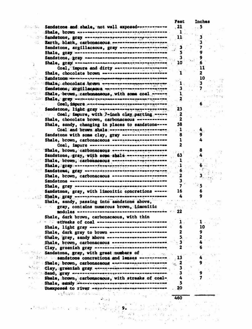
Feet
Inches_21
. 51 ..U.
Sandstone;.and shale, not well exposed.Shale, brown w.•-w. -~o• r...-•_-~,
Sandstones, gray ie4_, r._^--
Barth, . black,. carboneceou . --r-- .•----•••--r----
Sandstone, argillaceous, gray --,--4.-,-.Shale, gray 4s
Sandstone ; gray ..
.e...W .e fa _Shale, grey 4R.-.,S.MM....
4.4 _.4Coal.," impure and dirty -0 ,
Shale, chocolate brown -- --
SSandstone'a
wl!M ~.p.
-.,..Sham; .. ..chocolate Armen N
1A/I* iA.
Sandstone, ~gd.1lac ous, ~ i ~ ~-Shale, ba'arti, ._ :arboaameoes, :.with some Coal Shale,' grail ~• ~
C/o~al., .i
rei~~~ri. ..aY-..~Irr.-1►a ►~..~w+~...~... ws
Sandstone,: light gray -R-♦ Oti.t~.~•. .M'ri .~l
Coal,: impure, with,7-inch c W ;pasting ., -.--,Shale, chocolate brown, carbonaceous Shale, sandy, changing in places to sandstone--- -
Coal and 'brown shaleSandstone with some clay, gray Shale, brown, carbonaceous * ...... ....
oal, impure 1 1.00
.Shale, brown, . carbonaceous
•---Sandstone, , gray, -wi b sops Ala ,Shale, brown, carbonaceous -•-Shale,,: grayc...b .. .eArwa~.r _sSandstone, gray e w.~_- _s.Shale, brown, carbonaceous .............--Sandstone ----,..--- -------.1.1
Shale, gray -- ♦ 4,4
Sandstone, gray, with limonitic concretions -----
Shale
a 1•044444 M1..
Shale, sandy, passing into 'sandstone above', -gray, contains numerous brown, ;Umoniticnodules
Shale, dark brown, carbonaceous, with thinvtteaks of coal r
Shale, light grayShale, dark gray to brownShale, 'gray, sandy aboveShale, brown, carbonaceous Clay, greenish gray ---•-•--
...
Sandstone, gray, with great nuobsrs ofsandstone concretions and lenses
Shale, brown, carbonace
•- ••Clays-greenish gray _00..e...a
=Sand,, ..,gray 1► wy ' _i.10
Shwle,ibrown, carbonaceous, with streaks of coa lShale,. Sindy ri .v..'s•• ..xs., 1. ..04.,.44 f .Unexposed to river ,.Ka .f.-- s_-...1 s_ ~...
460
S69
22
32
,1323345
20
1 .
1 .6
102
95. 2
46
9

The Fox Hills sandstone, the' Pierre,_ Niobrara, and Benton shales, and the Dakota
sandstone are believed to be present in the Dickinson area . Of these the Fo x
Hills is most likely to contain Olt 'adequate quantity of potable water . Leonard9/ describes an outcrop of the Fox Hills strata along Little Beaver Creek i n
Sec . 7, T. 132 N., R. 106 W. as follows :Feet
Sandstone, light greenish-gray, massive 50
Sandstone, ledge, yellow 10Clay, sandy, finely laminated ' 25
This outcrop is about 80 miles southwest of Dickinson . The-Carter Oil Co . No . 1
Semling, drilled about 90 tiles east and north of . Dickinson, encountered abou t
175 feet of sandstone described as "Fox Hills- at a depth of 915 feet below land
surface . The top 70 to 80 feet was described as coarse sandstone . This forma -tion should be encountered`in the Dickinson area at depths between 1000 and 130 0
feet below land surface . 'The next aquifer productive of =odergte amounts o f
water is the Dakota sandstone . The"top'of the Dakota should be reached a t
about 5100 feet below land surface or at about 2700 feet below sea level . 10/
POTENTIAL WATER-PRODUCING'AQUIFERS IN THE DICKINSON ARE A
A. L ." Greenlee
The present well field'at Dickinson is the largest producing field known toexist in North Dakota that Obtains water from the Sentinel Butte (or Upper
Fort Union) formation . "An analysis of the type-sections listed above gives th efollowing total thickness of clay, shale, and coal, and of sandstone and claye y
sandstone in the exposed sections ; also the thickness of the three principa lsandstone beds in each unit .
Total thickness ,in feet
Shale, clay
and coal SandstoneThickness of principa lsandstone'beds, in ft .
Sentinel Butte(*Upper Fort Union) 307 113 80 - 12 - 12
Tongue River-Ludlow(*Middle Fort Union) 129 85 35 - 16 - 10
Hell Creek(*Lower Fort Union) 243 199 63 - 23 .- 16
Most of the sandstone are very fine-grained and have varying amounts of clay andin many places thin seams of shale . They have high porosity but-low specificyield and transmissibility. To produce any large amount of'water,the bed swould have to be of considerable thickness .- It is doubtful-whether the yield .from beds less than 30 to 35'feet thick would justify the cost of development .Of the total section described, only the Sentinel 'Butte and Hell .Creek forma-tions are known to contain a bed of sandstone over , 35 feet thick . ,Water maybe found in the seams Of lignite but it has & high organic content and a dar kbrown color and is, therefore, unsuitable for a municipal supply .
9/ Leonard, A. G., op . cit ., pp . 43-4410 Ballard, Norval, Regional geology of Dakota basin : Amer. Assoc . Petrol .
Geol . Bull ., Vol . 26 p . 1568, 1942 .*Nomenclature by A . G. Leonard
10 .
The Pox Hills .sandstone is!-a .potenti*l .'aquifer . though, it lies at considerabledepth. ,Test-drillingand test',pumpieg wAjl,.ba. required to - supply ,quart tive ::a sdqualitative-data needed to evaluate it, potentialities, ., However, three wellswhich have. been drilled to this formation . in tile.. vicinity, of Dickinson failedto obtain an . adequate ' quantity of potable-water, as discussed later (p .17-1$)
The Dakota sandstone is •ktowa to cgntain highly ,eineraliaed .water,in other partsof the State . The popr' quality of the:water acrd; its great depth in theDickinson: area : precludes its development for A municipal supply .
Despite the -lowering of the water table an ;,the_ eastern half of the well field,a few wells : obtain small' •quantities of water• at .relatively shallow depths .These wells probably penetrate bodies of peTchad:,watar that are held above thenormal . water table by the relatively impermeable lenses of . clay shale.' Test hole3B encountered water between depths of Siy and 53 fast . The water there was heldabove the, normal•: water table by the- underlying 44-foot bed of • clay .
The water encountered in the well field at depths less than 200 feet generallyis relatively hard but is satisfactory for most domestic uses . At depthsgreater than •EO0 'feet most wells encounter 'brown ; lignite-stained water that i srelatively soft but is> not 'suitable for public, supply because of its color.In,the vicinity-of wells : 3 and 6 this water . has ,been encountered at a depth ofabout 235 -feet .
PHYSICAL. .PROPERTIES OF WATER : BEARIt MATERIALS
Definitions and-geWA ,considerations.
The following discussion of the principles governing the occurrence and movementof ground water has been based chiefly on the authoritative and detailed treat -ment of the occurrence : of ground water by Meinser(1923), to which the reader isreferred for more 'extended consideration, .
The reeks that make up the outer crust qE the earth generally are not entirelysolid,- but . have .numerous openings, callad'vaidelor. interstices, which may con-tain air 'natural gas s . oil, : or water The number, sine, shape ; and arrangementof the interstices in 'rocks depend ypaa..trhe ,character of the rocks . The occurr-enae of ground water in any regign f_i,s ,therefore modified by the geology.
The :open spaces in • rocksvery greatly in sine . . Generally they are connected sothat ..vater can percolate from one to another* but in some rocks these oPenspaces are isolated-and ,the, water has little. or no chance to percolate .
The porosity of a, rock . is the percentage of the total volume *of the rock tha tis occupiedchyAnterstices .. A rock is said. to 'be saturdted when all it s , inter-gtif ces :are .f .lied with .water or other liquid, and : the porosity is then ;mutt-tally ,the percentage • of the total volume .., of rock that is occupied by 'water .The . -porosity of a .. rock determines only the 4miount of water a given rock can hold ,- not'the ' amount it may yield • to wells . Home- rocks, such as certain -clays, may, .be highly porous but 'vill yield only very small . quantities of water to Wells :
The rate, of movement of . ground water is determined by the size, shape, numbe rand degree of interconnection of the open spaces in rocks and by the hydraulicgradient from one point to another . The permeability of a Water bearing materia lis its capacity for transmitting water . The coefficient of'peremeability may beexpressed' as the number of gallons of water a day, at 60o 'F .,-that is conductedlaterally through each mile of the water-bearing bed (measured at right angle sto' the direction of flow), for each foot of thickness of the bed, and for .eachfoot per mile of hydraulic gradient (Stearns, 1927, p . 148) . The field coefficient of permeability is`expressedas the number of gallons of, water a day tha tpercolates under prevailing conditions through each mile of water bearing be dunder investigation (measured , 'at right r•angles to the direction of flow), foreach foot of thickness of the bed, and for each foot per mile of hydraulic grad-ient . The coefficient of transmissibility may be expressed as the number o fgallons of water a day transmitted through each section one mile wide . extendingthe height'of the aquifer, under a ;hydraulic gradient of one foot to the mil e(Theis, 1935, p . 520) . It is equivalent to the field coefficient' of permeabilitymultiplied by the thickness of the saturated part of the aquifer .
The specific yield of a water bearing formation is defined as the ratio of (1 )the volume of water which saturated aquifer will yield by gravity 'to (2) it sown volume (Harmer, 1923, p . 28) . It is a measure of the yield of,a wate rbearing bed when it is drained by a lowering of the water table . The quantityof water that may be removed from storage in a saturated body of material thu sdepends upon the specific yield of the material .
Behavior of the water level near a . pumped well
The following discussion has been adapted for'use in-this report from simila rdiscussions by Wenzel (1942, pp . 98-101) and other members of the United State sGeological Survey .
When a pump-begins discharging water from 'a well under water table conditions ,the water table near the well is lowered and a hydraulic gradient'toward .thewell is established . The water table soon assumes a form similar to that of an
.inverted cone with its apex at the well . For & short time after' pumping begin smost of the water that is discharged from the well is derived by unwateringsediments near the . well, but as pumping continues .water will be transmittedlaterally to the well through the Mater-bearing material'at approximately th erate that it is being pumped ; that 'La, a steady state of flow will be established .Continued pumping at a constant rate causes continued expansion of the cone o fdepression and further decline ° of'the water table. The decline of the watertable is completely arrested only after the 'influence of''pumping has reachedone or more boundaries of the aquifer and reduced the-outflow or increased th einflow thereby an amount equal to the discharge of the well (Theis, 1940) .
After the discharge of a well is stopped, water continues : tomovetoward' the wellfor a time under the hydraulic gradient created by pumping, but .instead of being
.discharged from the well it refills the well and the adjacent unwatered sediments ..At a considerable distance from the well the . water level may ' continue . to decline.for a time after pumping has been stepped because Water continues to move towar dthe well until the hydraulic gradient returns . to normal . As the sediments aroundthe well are refilled, the hydraulic gradient decreases gradually and th erecovery of the water level in the well becomes progressively slower . Eventuallythere is a general equalization of water' levels over the entire area affected ,and the water table tends to assume its original form, although in some cases apart of the sediments may remain temporarily or permanently unwatered .
12 .

PUMPING TESTS
Schedule of Operation
Web's 3 and,7 in the Dilckinoon well field were teat pumped during the investiga-tion . ., . Wall, 3- was pumgped continuously for , 49 hours at an average rate of 10 5gallons 's *note . . Per~6odic, sates, level measurements wets. made in wells 1, 2, 3 ,4., and S4 , in well. 3A, 'rich is an abandoned, well, and in well 3B, which is a testhole drilled during the investigation . Excsssive .vithdrawals of ground wate rfrom the eastern part of the well field had crested a" large, irregular cone of .depression that extends the entire width of the vell .field,. Because of the lowyield of the wells and the inadequate storage facilities it was not possible tostop all of the pumps and allow the water levels to recover fully . Wells 6 and 7 ,therefore,_ ware pumped continuously during the teat on well 3 . When the pump sin the eastern part of the field were stopped prior to the test, the water tabl erose p. idly for a :few hours but the rate of recovery gradually, decreased ,s othat after two. or three days the rate of rise was only a few hundredths of a foo ta day, indicating that the water table was approaching static ' conditions ,on alarge -cone of depression .
When the pumping of well 3 began, the water levels in wells 1, 2, and 5 wererising and they continued to rise during .a large part of,the pumping test . Anear-equilibrium cone of depression was not established at wells 1, 2 and 5 so,the water level msasurementsat these wells were not used'in'the calculation s
. of permeability.
The water level in well 4 rose and declined several times during the pumpingtest on well 3 . By plotting the water level . in well 4 and the water leve lin the near-by concrete cistern it was found that they fluctuated together .When the cistern is full it bolds approximatel y .830 tons . of water.. The weightof the water apparently compresses the water bearing materials sufficiently tocause a rise in water level. in the vicinity of the cistern . .As .the cistern'i semptied the pressure ;s removed and the water table .declines . Because of thefluctuations ofthe water table caused by the addition and'withdrawdlof waterfrom the cistern, the water , level measurements in .well 4 were not used in thecalculations of permeability .
The pumping test of well 7 was made about two weeks after the test on , well 3 .Because ofthe, greater_ demand . . for water occasioned. by -the Invest weather andbecause of a break daw n . 9f-the pumping equipment, in well 1 it was necessary t oPump yells -2y, 3, ; and.. 5 during the .test :. of well 7 . Well 7 was pumped . contin-uously 'for: 44 .5 hours, at <an 'average rate of 130 gallons a minute . Periodicwater . level that was at s avere . math .
n-. in ; wells 6 and' 7' and in we" 7A, which is .
a test hole that map drilled daring the, investigation .
Determination of Transmissibilit y
The data obtained from the pumping tests of wells 3 and 7 were used to deter -mine 'the 'coefficient of transmissibility of . the water bearing materials i nthe Dickinson well field . The transmissibility is the product of the permea-biiity'by-the':original depth of flow. (assumsd..to-be uniform wheg the wate rtable
in its undisturbed positioq,3
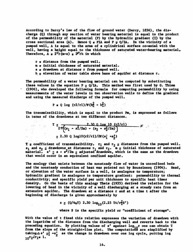
According to Darcy's law of the flow of ground water (Darcy, 1856), the dis-charge (Q) through any section of water bearing material is equal to the produc tof the permeability of the material (P) by the hydraulic gradient (I) by th ecross sectional area (A) . HenceQ s PIA and P Q/IA . In the vicinity of apumped well, A is equal to the area of a cylindrical surface co-axial with th ewell, having a height equal to the thickness of saturated water-bearing material .Therefore, A a 26r(m-s) 2rrh in which
r a distance from the pumped well .m s initial•thicknasa of saturated material .s a drawdown at distance r from pumped well .h, = elevation of water table above base of aquifer at distance r .
The permeability of a water bearing material can be computed by substitutin gthese values in the equation P : Q/IA. This method was first used by C . Thiem(1906), who developed the following formula for computing permeability by usin gmeasurements of the water levels in two observation wells to define the gradientand using the measured discharge of the pumped well .
P s Q log (r2/rI)/A(h - hi )
The transmissibility, which is equal'to the product Pm, is expressed as follow sin terms of the drawdowns at two different distances .
T
.Z-10_(t loq 10 (r2/rl )2tt(sl - sf/2m) - (s2 - s2/2m) j '
: . 2 .30 Q loglO(r2/rl)/21 (si -sZ )
T : coefficient of transmissibility . rl and r2 : `distances from the pumped well .al. And 82 drawdowns at distances r l and r2 . m ::'initial thickness of saturatedmaterial . s' : s - s2/2m ` adjusted drawdown, which is-the same as the drawdow nthat would occur in an equivalent confined aquifer .
The analogy that exists between the nonsteady flow of water in unconfined bedsand the nonsteady conduction of heat was pointed out by Boussinesq (1904) . Head ,or'elevation of the water surface in a well, is analogous to temperature ;hydraulic' gradient is analogous to temperature gradient : permeability to thermalconductivity ; and specific yield' per unit thickness to specific heat timesdensity . On the basis of this analogy Theis (1935) , derived the relation for thelowering of head in the vicinity of a well discharging at a steady rate from anextensive aquifer . The drawdown at a distance r and at a time t after thebeginning of discharge is given approximately b y
s : (Q/4eT) 2 .30 loglo(2 .25 TtIris' )
where S is the specific yield or "coefficient of storage" .
With the value of t fixed this relation expresses the variation of drawdown wit hthe logarithm of the distance from the discharging well and reverts back to thepreceding equation . By plotting values of s' against log r one can obtain Tfrom the slope of the straight-line plot . The computatiofl are simplified bytaking d ► s' =i -s2 as the change in drawdown over one log cycle, putting log
10r2 1rla 1 .
14 .

Then : T m , 2 .30Q,_21 iss '
The above method, was u.aed ' in• determining the transmissibility at Dickinson . Thedata for the pumping test of well 3 are shown in figures 3* and 4* . Bscauae ofthe decline in discharge shown at the bottom of figure 3, it was not satisfactor yto use the `drawdow ti : data witIout Sinking sooe adjustment for that decline. Asimpler procs~re was'to'wait faith' the . recovery observed in three wells andtreat it as 'though it Wets . a eegative'•rawd+own . The value of T was found tobe-about 8,300 salient; per ' day per foot .
Determination Ot , Specific Yield
The storage • coefficient'•is, determined from : the intercept of the .straight lineand the zero drawdown lane . ~utting ` e 0, it: is found that "
22 2;25tb/r0
where roQ is the distance at which s a 0 on the straight line . The value of Sdetermiied from this test is about 0 .001 which suggests that the water bearingformation is confined or semi-confined, at :least in the vicinity of well 3 .
The data for the pumping test of well 7 are shown in figures 5* and 6* . Hereagain, there was' a'declinet in discharge during the pumping, test . For thisreason the recovery method was used in the determination of transmissibility .The slope of the line (Fig . 6) was 7 .3 feet over one logarithmic cycle . Thetransmissibility in this case was found to be about 4,500 gallons per day perfoot and the coefficient-of storage was found to be 0.016 . This high apparentcoefficient of `storage may be due to the-fact that well 7 draws water from aconfined sand and from an overlyingtrnconfieed sand.
OUlk ZITY OF GROUND‘ WATIM
Yield of minidipal wells
The yields of the municipal wells at Dickinson range from about 60 gallons pe rminute, for well 5 to about 130 gallons pit minute for well 7 . Wells 5, 6, and7 are located on the west side of the hill and their pumps must boost the wate rover the hill in addition to lifting it ' .to 'the surface . , As a result, the rat eat 'which` these wells discharge `dater into the 'cistern is much less than the .rate at which they ditacharge •water at the well bii•¢es. - The three wells have atotal yield of about 320 'gallons per ' miute when ,al lowed to discharge at thowell sites but they, discharge •.only° 160`•gallons "per ainute .into the cistern . 'Thecombined discharge o~~ " all the wells except well 4, which generally . is not used ,is 417 'gallOns per Minute at the cistern .
Determination of '- stsadyistata" drawdova
AA that the effective radiisr of each well is 0 .5 foot and. that four wellsyialdtnB 100 apm each ate ' nasded to meet'the
d isnd, the effective radiu sctaph '*Fig . 3 -
or d a
es o*Fig ; 4 Time drawdownr graph for test of well 3 .
ig. 5 Graph of data from pumping test of well 7 .*Fig. b ' Time drawdown' ra h for test of Weil " 7
Y3 .'

of a battery of four wells (such as tells 1, 3, 5, and 7) is computed .to beabout 240 feet .
Knowing the effective radius of a battery of four wells such as wells 1, 3, 5and 7, one can calculate the approximate steady-state drawdown of . the Dickinsonwells . The four wells (1, 3, ..5, and 7) aresituated about . 6,000 . feet north ofthe Heart River, along which there assumedly is salvageable natural discharge .The river is considered to be a constant head line source of water .
Assume that T : 6,500 gpd per ft . ,rb (effective radius of battery of four wells) : 240 ft . ,Q (approximate peak daily discharge) b 576,000 gpd ,sb a steady-state drawdowna (distance to straight line source) : 6,000 ft .
Then :.
2asb 2 .03Q log1O
b
s = 2 .303 x 576,000,x 1o40 12 .000/240 a 55 feet.b2~t x 6,500 .
The well loss . of well 3 when pumping at the rate of .102 gpm was inferred tobe about 10 feet .(Fig . , 4) . , :Adding this to the computed drawdown of 55 fee tgives 65 feet. for the probable total ultimate drawdown when four wells operatecontinuously . This leaves very little margin for future operation at rate sexceeding 400 gallons per minute because the thickness of saturated materia lin the Dickinson well field ranges from a little less than 30 feet to a littlemore than 90 feet and averages only about 75 feet .
CONCLUSION
It would not be .practicable to drill . additional wellS .in the existing well .field to augment the water . supply for. Dickinson because the present wells areequipped to pump 'more than 400 gallons .a minute (an amount sufficient to causea drawdown of 65 feet) . This is based on the . assumption that the permeabilityand thickness of :the water bearing materials are . the same for the entire areaas they are at the well field . Approximately 40 wells and test holes , havebeen drilled in the vicinity of Dickinson by the City and .by the .NorthernPacific Railroad Company but most of them were abandoned because of a lack ofadequate potable water . The thickest and coarsest water bearing material swere encountered in the well field, and therefore it is not logical to assumethat the thickness and permeability-of the water bearing bed . are as , greatadjacent to the well field as they-are at the well field. The early Tertiarysediments that underlie the .Dickinson area consist preddominantly of clay andf ins sand . The sand beds vary greatly in thickness . and . may pinch out inrelatively short distances . , In addition, the ratio . of clay, to sand and hencethe permeability may vary greatly within short distances .; Many test holes. ..inthe Dickinson well field have been abandoned ' becauee the water bearing sandcontained so much clay that it was not feasible to develop a well at that site .
16 .

Drilling., to greater depths in order to obtain an adequate supply of water als owould- beInadvisable-=because of the character of the underlying sediments . 11/Three wells have been drilled in the nicin ty of Dickinson to tepths .ie-excessof 1,000 feet (1,200, 1,800 and 1,823 feet) but none''obt'ained -an aadequatequantity . of potable water .
It has ,.been suggested that a solution to the water supply problem .at-Dickinsonmay be the impounding of water in the Heart River which flows past the southernedge of the city. , .Studies have been made of the Heart-River in the , vicinityof Dickinson by the : Bureau of Reclamation to determine the feasibility ofimpounding water for municipal, industrial, and irrigation use . It has beenestimated bb therm that the average annual discharge .of the Heart . River atDickinson it about 12000 , acre feet `' (approxiasately 3,,900,00O,000''°gallons) .*The quaf tity of eater available -frea the Heart River .'wouldbe adequate: for. theneeds of the city, allowing for moderate growth . The storage reservoir .shouldbe sufficiently large . to impound adequate water for the needs of the city durin gperiode ,'tf emall'streem'flow. In the event of prolonged droughts the well scould-again be pumpe .until adequate water had been impounded in the reservoir .If cooler water is desired, the wells could be pumped in .the summer and surfacewater could be used during the rest of the year . Becautte- of ' the better .qualityof the river water, however, it probably would be desirable to.-use : it. : ' aa mwchas possible .
Automatic mr ieu l recorders have been installed on walls•MA and 7A so that acontinuous record of water levels in both sides of the'Well fiel ds can be .kept .This will allow for properly balanced pumping on bet.. sideut.: of 7 the field. Inthis way the city should be able to obtain a more economic distribution ofpumpage' and to delay somewhat the decline of pumping levels. -
This investigation has not exhausted the possibilities of ; additional groundwater supplies at some distance beyond the influence of the present well field .However, the results of test drilling 'helve not' beeteencouraging. on ; this score .
WELL LOGS
The materials encountered in test holes 3B and 7A are described below . Theholes were drilled by a cable tool drilling machin e. owned and operated by theMcCarthy Well Company„ Samples were Collected by the driller and the descrip •tions were made by the writer .
Log of test hole 7A, 99 feet southeast of well 7 . Altitude of top of casing ,310.81 feet above datum. Static water 'level' 48 82 ' feet below top of :casing,
. .
May 28, 1944 .
1'hi4k ere s
DepthFeet:
•
FeetSoil, brown, 'sandy 5 5
Clay, sandy, gray and : tan ; containingthin seams of lignite 20 25
D. S . Geological Survey : Water 84ppiy'Paper'598, p . 226 . .*Personal communication, Charles T Mite, Engineer for Bureau of Reclamatio n
11/ Simpson, H. E. Geology and-grouad eater resources of North Dakota :

ThicknessFeet
DepthFeet
Sand, very fine, gray, containing clay ,lignite encountered at depth of80 feet 60 85
Sand, fine to very fine, blue, containingclay, gray 41 126
Clay, blue-gray 6 132
Clay, brown, containing thin beds o flignite 10 142
Loge.of teat hole 3B, 75 .5 feet northwest of well 3 . Altitude of top of casing312 .16 feet above datum. Static water level 129 .12 feet below top of casing ,
May 14, 1944.
Thickness.Feet .
.DepthFeet
Sand, .fine and clay, gray 8Sand, fine, hard, bluish gray, con -
taining clay, gray .
Water en-countered between depths of 2 9and 30 feet . 38 46
Sand, fine to medium, poorly sorted ,bluish-gray, containing silt andclay,, gray.
Encountered thin"bed of lignite at a depth of 46 . ft . 51
Sand, fine to medium, bluish gray, con -taining water 2 53
,Clay, dark blue-gray 44 97Sand, very fine,;'bluish,gray, containing
clay , gray` 31 128Sand, fine, bluish gray, containin g
clay, gray 29 157Sand, fine, bluish gray 34 191
WELL SCHEDULES .
Well 1
Diameter:
:20 inches to 12 inche sDepth :
191 feet on April 1, 1944Driller :
C . L. TillquistDepth to water :
107 .20 feet below measuring point on April 1, 1944Measuring point : Top. of'4 inch hole on east side of concrete pump
base which is 0 .88 foot above concrete floorElevation of measuring point : 302 .61 feet above datumPump :
TurbinePower :
Electric motor (15,horsepower) :Yield :
100 gallons a minute .(reported)Draw«down :
19 feet after 24 hours of pumping
18 .

Well 2
Diameter :Depth :Driller :Depth to water :Measuring point :
Elevation ofPump :Power :Yield:
Well 3
Diameter :
20 inches to 8 inches
Depth:
182 feet (reported )Driller :
C. L. TiliquistDepth to water :
X28.92 feet below measuring point on 'April 14 ;1944.Measuring point' Top of .5 inch)IOI.s`in side of concrete pump base
which is 0 .53 ' foot- above concrete floor of pump house .Elevation of measuring point : 311 .60 feet above datum` `Pump :
Turbine
. .
Power :
Electric motorYield :
105 gallons a minuteDrawdown :
33 .14 feet after 49`bours of pumping
Well 3A
Diameter :
8 inchesDepth :
191 feet on April 11, 1944Driller :
C . L . TillquistDepth to water :
129 .50 feat below measuring point on April 14, 1944 .Measuring point : Top of casing which is . ,1 .9 feet above , land'surfaceElevation of measuring-point : 311 .88 feet above datum:
Well 4
Diameter :
8 inchesDepth:
170 feet (reported) 'Driller :
C . I, . , TiliquistDepth to water :
97 .72 feet `beloa+ measuring point on'Match 31, 1944 .Measuring point : Top of 0.5 inch hole in west side of pump base whic h
is 1 .0 foot above concrete floor of pump station .Elevation of measuring point : 298 .92 feet above datumPump :
CylinderPower :
Kerosene engine (15 *horsepower )Yield:
50 gallons a minute (reported )
20-inches to 10 inches196, feet (reported);'C. L. Ti2quist124 .54 'feet betow'`measuring point on April 1, 1944Top of 1 .5 inch hole in northwamt side of pump whichis 1 .0 ' foot ' above concrete floor of pump house .
measuring point : 306 .45 feet. .. above datumTurbineElectric motor (15 horsepower )100 gallons a minute (reported) .
19 .

Well 5
Diameter :
20 inches to 12 inchesDepth :
154 feet on April 1, 1944Driller :
McCarthy Well CompanyDepth to water
92 .14, feet below measuring point on April 1, 1944Measuring point : Top of 5 inch hole in north side of concrete pump
base. which is 0 .65-foot above concrete floor o fpump house
Elevation of measuring point : 310 .37 feet above datumPump :
TurbinePower :
Electric motor (20 horsepower )Yield :
65 gallons a minute .Draw down :
33 feet after 60 hours of pumpin g
Well 6
Diameter :
20 inches to 12 inchesDepth:
135 feet (reported )Driller :
McCarthy Well CompanyDepth to. water :
48 ..64 feet below measuring point on May 5, 1944Measuring point :
Top of 4 inch hole :.in south side of .concretepump base which is .-O .47 foot above concretefloor of ;pumphouse
Elevation of measuring point : 310 .29 feet above datumPump :
TurbinePower :
Electric motor (20 horsepower )Yield :
124 gallons a minuteDraw down :
13 feet after 24 hours of pumpin g
Well 7
Diameter :
20 inches to 12 inchesDepth :
140 feet' (reported )Driller .
McCarthy . Well Company .Depth to water :
51 .72 feet below measuring point on May 5, .1944Measuring point : Top of 4 inch hole in south side of concrete pum p
base which is 0,52 foot above concrete floor o fpump house
Elevation of measuring point : 314 .02 feet above datumPump :
TurbinePower :
Electric motor (20 horsepower )Yield :
130 gallons a minuteDraw-down : ,
43 .0 feet after 44 .5 hours . of pumping
20 .

REFERENCES
Bouasinesq, J ., 1904, Recherches the6riques cur l'ecoulement des nappes d'eauinfiltrdes dims le sol at sur le debit des sources, Journal de mathema -tiques puree at appliques, series 5, volume 10, pp . 548 .
Darcy, R., 1856, Les fontaines publiques de la vine de Dijon, Paris .
Meinzer, O. E., 1923, Outline of ground water hydrology, with definitions :U. S . Geol . Survey, Water Supply 494, pp . 1-71, figs . 1.35 .
, 1932, Outline of methods for estimating ground water supplies :U . S . Geol . Survey, Water Supply Paper 638•C, pp . 126-140.
Stearns, N. D ., 1927, Laboratory tests on physical properties of water bearin gmaterials : U. S . Geol . Survey, Water-Supply Paper 596•P, pp .121.176 ,figs . 1826, pls . 11.13 .
Theis, C . V ., 1935, The relation between the lowering of the piezometri csurface and the rate and duration of discharge of a well using groun dwater storage : Am. Geophysical Union, Trans . 16th Ann. Meeting, pt . 2 ,pp . 519, 524, figs, 1-3 .
Theis, C. V., 1940, The Source of water derived from wells, Civil Engineering ,
May 1940, pp . 277.280 .
Thiem, G., 1906, Irdrologische methoden, Leipzig .
Wenzel, L. K., 1933, Specific yield determined from a Thiem's pumping test :
Am. Geophysical Union Trans . 14th Ann. Meeting pp . 475-477 .
, 1936, The Thiem method for determining permeability of wate rbearing materials and its application to the determination of specificyield ; U. S . Geol . Survey, Water Supply Paper 679-A, pp . 1-57, figs . 1-7 .
, 1942, Methods for determining permeability of water bearin gmaterials : U . S . Geol . Survey, Water Supply Paper 887, pp . 1-192 .
figs . 1.17, pls . 1-6 .
21 .

I
00
Fig 2 Profile through well-field showing decline of water level of Dickinson, N D .

8590
i'~blire 3Graph cf data from ,upn1r. test of well 3 .
.30
/60
~~ .1 44
4 t{} ' 1~~~11 {}~~ li{+}}Il ' ki r
-i -
{ WE t 3,8to.
I/Mr,
+3 z
.- 4 1-4
rv
44-.4
. . I j
. .
- 1
tt
}
1 '
r
_
1
{
!
rt i
1
t
t
'~"-`
t
Y
I j
mot -
j . .
':-+
•
k
'
-
1
;4
F
t
1
i t 1
-
It rt
-L
r
LIL
.. .
t..
,
't" ti-f4
. . .. 4
{
j rf
;{ r
f
++
"
I
j «
1 "f
+a µ
. .. f
(
i t
i .IIIYu iuwia ~IRWiti~April /4, /944
/5
/6
/7

i.s/ft OmCOCA.0/ t/hrs./{ mi p 'tom uminuuuniurnu nWN +tiuirnMMiN 1r~"' NWN 1 U ~- -41.-t Yom,.:77 3-7- MggfII1 N !~IHN::lNNNMNN p~N MINNIIIIIINIMMMINNUIMNINHIUUNIMMMIM INhilll:!!' Mlp~ ` +~+ + rnurn NINIWIININMMINIa1NM IMINI N06 !!tINNIM111Nlal! NMMINNNMIMNNW MMiMMMIMN .. WNMNIIUNINNINIINIHI NNINN4x IIINNINNIHNUNIM I MIIa1HIINIMMIUN rnIINUUIINIMWNWM O NININNMMNNIMMIIMItMWNI NNIMMMMMNNMINNNINNIN N IMMMNNININIININMMNNUMIMMNNNUU MNMIMNNN, MWIU MIMWMMIHIINNHNHIWNMHUINI tMNMWIIN NHMHhiiiii "INININMIr iu IIIIMIUNNIWWNIMUINIMINNnMN NNNNNM N:!!IMWINMMI MIHINMIINRIINN IMINNI rn11NMWWN NINWnNMIMIMMNINWariii.:' IIIUINNIIIHHIIIgnIIIINHNIINNIInIW111NN NMIIMNIIIUIINNIIMNMIUMWNIN IIIIIINIIIIIIII111111a1uNrIglHlnuWlttNNN t. MNINIMNNMUIINNIMM lIWI p n NINIII H11MINHIMMINIINMIINIINNIN I NUlINNNNNNNNINNNMNNIMN NNMMnnMNNI INIIIIIIHIIUNIMINMNN111IINIM1uhN NIlt IMIHIINNHNNMIMNHIMMIMIIINIININUIIIIHIIIIIIIluINIINNNINIMIMMD M,.a NIHHUINNHUWUWHNNINNIINIWNIMINS. -n IMINNIINHtlllrlNUIMNINt111M{NWINWlI ~_ IIHNMHNINNINNINIMIINMIIIwHnwNIN NIIIIIUII1NN11HNltNIIM!11!n1111UNNWINNN MMIMNNWNWU~IIIINIIIIItNWUIUIIs.:M _ 1HHIIIuII1IIIIIIIIIINIHIi1NHIIIINIMNMWIWt MNWIHIIH IMNIIINMIHNIIip . .i ,sI 11H11NINIMINNIMMIUNINNININMMMI INNNIMNIMMIM!MMINIMMItININ.•!UINIHhIHWIH HlUhMN11NHgll moll l! NH111 NN NNMIOM!MNINNIINUIIWNIN NIHuiIMIMIMIMi Iiiiuu ININNnui MINIM 'IMIG;: u+HWHIN11111MNNINOW:NwAnhr::'"!IINItN!11111111NMIIIIINNN111 NINUHINWIIIIfM111N11{MINWUIIIIt i + + MINN MMNINHIIIMMINNMM{ nNNIIIIMM IMIIINNIIIIHIW 14 2InurnIIM!MI1111HHINM11IIIIMMIii;:,;9NNIHINNINNiilm INNUNNUINUNINNININIIMIWHIpII HIH1 MINNMO ssa~p UL~pIAN nNNIIIIIIIlet1N11tIN1111{IUIIUNMINiiiMt!+truIIHUINNIIIMINIINMII10MI1U,Iii:!!NONIMMI NNNIIINWNHHININMINHINtNN MINIM 1 ~p NMNNINNIWk HINHI IANNNNNNl11011 NINIWIN►r~liNMNNNIHNIINIII►11111111II11NIIIINIH1111111W11uri: I ! NIIINgIgWNIIIUH1U1nINIqHltql ! N111111 IIUINWNM1UIIINNINNWNN NNNNIIIII''ia1111t111g111N1!II IMIIINHININIiIIIIIIIIIUIIIHIINIIIIINNINI INHIUINNM +._ IHINININNIUIHIIIUIHMNINWUUI ,.~ N INMIIINMMIHIIINM 1 IIWWIINNI MN11NHIII INNiI111IMM1111IMMIIINNIHIIIIIIIIINIMMIIMMIHNNIINNIN IIUIIIIUNH ++± N M HMNIINMINIWNNIiI N I * N UHlNunwIHNNM m 1nst nNNINIMPd11N11NMIMM NIIMIINIIIINIIUIHt NNIINNIMMIUIUIU111111NHIHNIMUIUIM INIWN i MINal!!uNII11NI111N11111UnmrnuMII1 + ! N11 IgWIN NMINiuii a NuI 1W:iId'.i:1MIMIMMIH1t MNIMINIHIIHINNIHNNIIHIIIMMMUQINIMNIMIMMOMNI INIMIMINNxi:"7!rNINININNINNWImII NHHINIIUIIMMIdMIN NIIIMNIUNNIN INFNIn!IIIMNMMIIIIIININNIIIIINNWHtitlHNNNNIINNIINtiNNNNUNINMINMNIMWN ' HHIMINNNWIIrIWWun...!NNINMHNN{WI INIININNNM MNN NWNNIIHH III►:iI:!11NMINWHIIIft1M1111MMI N11MtlliM NNHNMIIMNuNNrIaWWMt~UINWMN NINMINMMWIHNNMNNI ri::::9IMIN /NMNNININHIIIINIMI INNIMI UIlhhMMnINtNH; IH6ll li:IINIIINIINNHNNIMNNINIMI H1!MII4NNIMIIIIIIINIIIIIINMNN NWWIIN +* 4. (NIMMIUNNHNIIUhuhhIIUIImnINU iiiii~iii.i eiiiiiiriiiiiiiiiiiiii+iiiMINIM 1CINMNMIIWNINNMMIN1111HN111HIINiMnNN1111111UIIIIIIMtN1111 MOWN IIMMNtINNdN 1NIIWNMWNNIIMMNIIIWWHNMINNMMINWNNIN !IIHIM111NRMM~q IpMINMINIWItNIIINt H P;1ININNMNHINIMIMIIINIINIftIIN'NIHMIIINIMIIHIUWIHN NMIIIIM' } ~ ia!!INNMNNMUINMNIIINWNI MNHIH IV!.IINIUWINNIIriHINMNN11 mimlINNIIIMI1111NIIIIHINIt!IIIIIpINNNIIMII I t `1 NMIIIIunuun1111NINNMINMIINNIIH NHMMull: !MILAN 11NIWNNINI IIR~VN NHHNINIii11NU1WI111H11NII11N11111111NN11!IIIILAINnMnNNf111NitN111NINN1I1111NMi11NNMMi NNININMtIMWIWWI1111N11NMtuMIWUllllt U$IUuIMMNHNNNii~ !!QIPgIN HIhIUIIIhI NNIIHHNI':!1NHWIIINWIIIi111NNIN111NIIHliIlN NNIMNNNIIMIIUIMNNNININI INNIN MN NMIIMNNHIIMNNINIWINWWIII~p1~~ NWWIi x'..'uil^NNNtN NNUNHIh:IINIIMIIIIINNINNINIIIIIf111Wt11t111IntlnNNIIIIMNINIIINI,,ii,uINNINnM11MNNMl Mfl t' *' ~INWNWH~MHIIUI{IIHIUWMW ININIMIINMWMmium MMIIMUuuh: . MnNNIIIIHI!Ii:NMnIN111N111NNHIM1UI111111rntul!1!nMNNIIIHINIIIINNNIIIUIIIIINIMIMHINWWNIHli IIIINMIMIMINIIIIWIItIMININNIIINWNIflINII _r NIMNN NNINNIIINMMUtIINHi uIH r:r.. H:i+;INHu iRa:!NNNIIIHININIHMIIIIIIIIIaINIIt11N11NINIHIIII!!i!ti NnMnNMNUNNNINNIHHIItHIIHPVIMNNNINWNIHINI IHIHMNINNNNIWNNHIIMIINMHNIININIINI NINNINIHINNNWWNII IMNIMNWiIINrtil [)~;:'e1Hi NIUNWI111NIHIHHIN111MNN1111111ItdH NMnMNN111H11111111111111IMMIIINIMINNININIIMIW IMMMnMMNNIIHNMIII11111I MOU1N1111111N IOMUHIMI nMNnNNNIIIINNIWNUINWIIHMIININIgliltlll Oll/lu: '!lhIhIWINlll1'i.:I!,: '7ST"'::"+""::"gi!1! B/nniaHIIIIIIIIIIIIIIIIIIIIIIu INiIIIIN111Mlllrn HIINUMMMNNNIHN1111111111tIIUIWIIIN11N111NIMWNIUUi MNNN111HINII11111NNNWIII~pIMtItNNlglll nIIuuUhIIIIINIIIIStiii:'++N++.PIp1+H!+y+ 1+nHtnnnNNHIIt11U1t11IttIHllllllllltllI UHIUNHUI1gIHfHNNIUUI NIINIIH11111111IIIIUtlIMUt11HIN11INfhiII$II MIn. .„MMNNHIUINIINIMHHIMMIM NINNNNINNHI! MNINIHIIINIIIIMHIf11Na:,ii:: 'ItHiRfliit HiiI: UUIIIwIUU UIIIIIIIIIIIIIIIUliIjUUHNIhNNNIII NIIl I Ii.mMM f1111N1111iIIU111iIIiI I i11111111I1I1N111111I11hI NNNn pN/1,N111IHIIIpW II IIHUIII11111IIIINIIH IIIIflOI MM.Oa II%IUIII INIUIMUlNI nlllhIU 1NIU It IIIIi111UA1BNNNNHIHMMIMNWWINNM11MINHNINIII~ NN/dil:!'u1:01MMMIMImUIUNIINWIIIItIt30354-NhnnMNIIIIINIIN11111111111udHlflHpti;:!!rrddllddtiiHNN NM NHMIUIullu ouliIIIBIIIIIIIIIIIIIIIIIINUN•NnnnNNNNnnNNIIMIIII11111111111IilIItilHIIUINIONtNNiii:".. +hNnN HINNINNIWIIt1NIIIH111111111NINfrtlfhIH'NN / NrnnnHNIIIIINIfH11MHH1 MMIMNNINHIHdfN M NINIIINNNINIIIMIUNI:MIN11IM NIHNIII' MnannnIIINNINNIINNNINIINNHu$ NOINIM IIthUI * !IIINIHININIntngmuH!nIN1N11NHINUnNN/nnNHHNIIUNUNMIn,nHfHx!IINUNiNltfudlaltu ~. 1 1:!„IINN18HUIUHWNUNNd!Ndddat11HN11111t11114-4-4-t-4444i + Ixs..t111NUIIUIINIMMNnNIN/NUIN MONONNM!nNNIInnuINIWNn11W11N1 NNMIMNIIHIN 1NIHINIIUNIUlIff NNINNINIMNINMNUPNINNNMMINMI NIN IIIININIINNNNi1•NNNriii;!!!elllllll Y T1 4 _4 44_4 , rnimtnNWHIMIHN iuw.ut tna ,UNIHnIWNNNIMNIUMIWN11W,NMIN NININMNNM MMINIINNIIINNIMINi+tom,--a.-lIUHIIMIININMIMMINININIM I NIIII WININIMINMIIMWIIIa NNIWN I '+_n1. 4 ANI1NttNY IUUINNInNNN~INWNNWhl INIp NIHHIMMIHIMNMIMIIINHMN II i1WNNHlI NNINWNgi NnN }+i. II NINNINM!'.-T444 -44,.4- MI=Nnti tNNN r~d~l MIIMNIWNnUIiUSI 1NN11IHMNINl N MN MNNNININNIIIIINtINI INMnlau f N/NIIIIMNIMMINlriiiN!!+IINNMI NWNI nMHNINMMIH INIIIN IIMIMf INNIMMN:'!IMMNIfINMM auINHNINNNIIININNNNNI ; "+uIH uNMWtpp NNIIMNIININn'NIHh IINaim I linSMMp1NNIIIIIHIN t IHIINIINNI1111 BNIIIIIIIIIIINN/NIpNMINMNIINNON u1NuHlNdNWUIµ IHIWINNINNNIIHIN HW IIINUHNMNMMNIMMINIMNHINNIMIIHI !IHIMIINIIMINNIN HINNNINIMININIIINNIMMM IIIM111MMt INNIMITI W=MUNMMNNtUIIINNI N II MWINMMNNnNgNMI NIUIIihttMtMI WIMPNIIMI NWWNNIH1NIM 1NNUWaIM MNII INMIMMMMINNNIMINNNNNIMM MMNMNIMI~M NN + I IMII NHIINIMIINIUIInuht nnuIIIuhI1111NNH11WNiItH a•nnnnl1uHn111/11lhIIIIt111Nllllllrl!U IIIIIIIIn1111N►u a'IIIIIIuIuIuun nufIHInNINIIIIIIIIHItIIIHra•nnnnaIIIIIIIIIIIIIuuIuIINIIIIIHiu11111111nuI11111I,HINNINIINNNINNMIINNIIHNNNIn►hNRN//NNINIIININIItN1i111WINfIhInIuutIMINIIIHI,IFNIMM N111MHII INIIIMN IIWINOMMMNnnnNHNIHU1NNInlNWNUItllln IIIIIH ulntN!NIIN111U111 INNNI IiuuINNIINMMIN1t NnnnnNHI/NNNNINIMHINnffWUNNINIUgfNmm:NI 1. INNIgtH NIMINMININIWHINMIUIII INIIIWI HH:1 MINN ISMS 1 INN 1MIUININNI Muumuu, _ ~ ~, , NNIIMMIHHIWNINuNIA IIIIINIpIHNINNN►NINNNN;.NnI& MpINIi~...WIIMMI MONO 1.INNMIMNINNNINMIMIMIMPtIpM NMIN1UU nWWNUIh ~. ~. 4i HIM11IMMM 1IIIn1 IMIIINMMMII'HNINUNIHINOMMM111INNHIHNIINNHIN !l I t N NeaNINNHIIHN+--#+4+!- ± II IMNNNHINiI4-44+HNNIMIN IINRUUNUININNNIUMIIiIHU MNNINNINININIIHININNHIIHNININNNNNI►In ifiNMIMMINIINNI11UINIMMO MINMMIMMOMuuimuIHMINMIINNINNIHIIININIMHMINNwMMINM'INWIHNMIIIIMMMMIesso4.1Po•Z.~/0 0p O J 0 0 N U ► U O J e 0 U J 0 0 N Y ♦ 0 0 /CIO0 o

/0.0/1.4.)
C0
:
. ,,
,,
.. . .. ..
.. . : '.: .
'
.. .. .. .. .. ..
-
"h.
't
' -4 444,1 - 4 . .4 .-i-444.4.444.4.
- 4 ,
.-,4- 4 .444
__ ----+.-.- 4 4
4' '41
--•-• "-t-
4.'4 4t
4 - 4 • •
-,-4-.-
4 . 44- 4 . . . .
.4 +,.-..-4-li 4 4
4 -4444 4-44 4 . 4 4 +4 4,4-444 ,
4 4. 4
. . 4 ' '
4-' 4
.
' •41-4-4 . 444,44,
4 .
•
4. :
•4 t 444,- 4L
,, 4
+-4 4 •
•
+ 44, 'L 41.44414
44144 4 . .4 .
„ . ,- .4-44 .
. . .
. 444 . + 4+ 4L
?" t4i, -44-4 44. 444 44+4 4 , 444 ., '44'244 .4-444t'': 4,, 444
'
. . . .
I • 444,444
4
.
. .
.. . . . , 4 44+411 4444.44444t
.44 L . 4 4
, t, .,
' .'
•" - 4444
1.
- --I .
• 4 4 - +4. • - 4
. •- 4-- 4-4-44---,+4 4 - -4 44-4. ;
-
-
14 44
.4 .
,
4 4 . 44,4
4
4-44I 4
4 -44-44 4, . ,41
-
4-44 4-4 •
. . .
-
4_4 .1-. . 4 . .
_. . 4 . 4
. - -4 4.,-4+-..-
4 4
44-17:47.r.r.17-st-Mat-,444,
''
.44 4,
4
..
/oUl 0 -4 3
C
2
7'4
t ; 4'4
'
74 44
t/hrs
o-
t-t
-+ 44-+-+-4-+
-4,,44 1- 4--14,41
4+144+4441
44-44 1-1--.L-n
1+
41++, 4444444IIINNINIO 4 + -
IM IINNINPWWI
4 .4. 4
4444 4. 4-4-4-44-4-44+44.444-
44I. i•4144-4-444144. 44444 44 4..-- { 4 4 . 4 4 4 4 41 4 - 4 44 . .
{4 4415
4 41 • " -l++444+44 . 1+ i t »44 4i • 4 +
4 . ++
.. 4 . -.L..,//-4-4,+444+44444i' 4 t 4 5 , f
----I - .4
..-4-H-•n
.4 .4-4.«t.44, . . . .
4-i-44.
.44
•4 4 4 44. -4 444« -4444444444 4 4 4-1
'
,r
,
. , .44444 444,44 .44 .4
n 4,,,44ut
4
. . . 4 . .
. . . . .»4444 444,4 4
,
T.-.-"-,---, , ,
-- . -• --t
--"-,i---,
.
.
.
. . .
. . 4, . .
,
4.4
'444,
. .
4444 . . -4-t- ..
,
,
.
,
+ n
n • 4+4-44444 4 11
1 4 4 14 . - 4 441 11ILIL,L
'
4•44.441+4t14-44--,44-t-
.
.
.
. .
L
1,,
' I
4. 44 .4.4,444444,44-44+44-44-44-4,44 - . 4 .--4...44 4-44 :4
i
1 1
t-4 .444-44,14-t-f444441- 14,44,
4,
4, 44-4,441 n+44--t-4+.
't
L .
4 4WNNMNNNOMNI4-44-44-4.44 4
.
. . . .
4
44 .4 . 4
.
{» 1NNIIN + 4 4 4
.
.
. -4,4,44--•n s 4 .
4 I
L4 1•-4 n4
-. :
f4'14414 -4 44 .. -4-4 4, 44.4 144.444
4 .444,4+44-t-«44 144444 4-
4 4,4 4444 44444444t . • 4
WNIN 4 4 .444 4 4-4444. 4441 4444.41 4
4,-+ 4 ++- 4-4+4 444 .4 t
,
,«
4,
4 4-4,4.4,44.444,4 .4
4 444441 • • 4 4,4144 '4 ' 4
'
'
,
•-4 -+-,-
.4444
+
+
4
t
. . . . 4 . 4,4 4 , ,4,„t
- -.4- .-. . -
MINI'
,
+
+
•,+f++ Nium l=giftMINN 4
,
. a . 4444, 44
.
4
.
.
.
i ,.
. . . . .
. 4 .4-44 -44441 . -44 Ng
4 - •
• 4- 1 ,4 44-44444-41-
NNW, 4,444 °0
-4, 4-
,
.
4
4 114414 ±444141-4-4 4, 4 '
44444+- , 4
444-
-f
-4-4 .L MltNN. 4 -4 4.
-4
44 . 4 444.4, 4,44444
•
4 • •44-y-4444-0-4.4,4414. 44t+44.44444.444,•44,44.t-n
,_L44
NI
We44 . 4 .. . . 44.44,44
44,4
;4 -tit44'
4 -4. 4
4.44.4-44,44-41'414
4+4. Vin
4-4i4
-+4
m:441.1.4 -.+, .4444, 44.4,,,+-. .
4 4-+_4. .4 4 4 4-4 4 4-4- .4-4 ,
t p
4
i
.--.t.,,-4
.
440447
' '. . . .
.4
.,,.+,
4 i
NIN,
4
,4.
: : ...
4-t-4.
4
i
MtINN*
4,
444 «44 4 4 n-t-•. 44 4,1 4
+
4t
7
4
14
4
I L
4+-- ,r '-' . 4444 .4+4- L44T
1 4.
. . . .
. . .
44
.
- 4 4
4--4--4-14-4
4t .
. ;
4,
4,4 • +4 . .+ .t
444 «44,4 ,
.4 44 .
. -.444, 44.4. 14
,
, + 44 ,-
4- -.4- 4- 4.
. . . . .. . . . . . .
.
. . 4
4
.
.
41 .4444. . . . . .
444
44
4 4,441
44-4
" 4- , *
•
-4
•. . . . .
4144 "'NINIINS •..
n 4
•+f 44 44 .44,4t .4.4 .4-
1-'T Mai- "I-4".4 .41 •44-44•4«1, 44L . -r4j.444
- ' . . . .4
4
4 .4 4
• 4-
•4
•
'44
44-
4t'"" - .41,1144-4441
f' ''''' "4' 7'
44+41 .-n "t-
4•4kt 44 .4441 ,
- 4
4,
. .
. .4 - 4 4. . :. yam«
.4.44 .444 4 .-44+4444444444-4-4, + 4 4
t .'
.4t,
„IM&44-4+4 44444
* 4444 444 44 .444,44,+4444,4+444+4some ,4 '" -
. . .
4444 4
41 . . . . . .....41 14-1 -44-4t 4
.4444.., 4"
. , 4 . 1444-4 4 . 4 4 + I
4
4 4 11+ 4 *MIMINm,u,mk«4t ..-444.
.
. .
i .-4 t---4 , .+ 4
-"
+ 1
44
4. . . .
.
..
. . . .4- 4,-44 4,4 ..
4
444,44 .4+ 4. . . . . . . .
+
-
44 4 4
4 •
• 4 +
- .4 " 444-4 41i- 444 ' 4 44 -44.
4
.4'
4-
'
4
- 4 +444 -044+ .
mulloulmNom"
.4
4. 44-4 441+4 4 , 414 .44-4444144f .-• .t44114' .444, 44.-44-4 .4.44-44.4 .4.4-444,4 4- • 4 . . .4-4 .4.4.4.4,444 -44 . .
. .444444 4- .4 44444 4 ,
4
-4 4+-44-444
' 4 t
'4'4 4'
1'
.4-'1 4,44444 .44 . .44 ' • ' 4 .
4 .
-14,-4 4 - 4 n - .4 4,-44 ..; . - .44444
, 4 .i-,44-1..44-4-4.4
- . „ . . . . . . . . . . . . • 44-4, .
.
.
. . . . . . .4 41 .44t,,-
., 4MNIID
- 4 .4. 4 .4 .... . ,i _44444 ..4.4 4 .i .4
L.-444»- 444..44 .
. -4 INNW, 4-44-- 4 4444
+4 -4,4.4
4.4,444 4 4 4 4
44 4 INNNMNM N06.11
.t 44+,
. h ..444'4, - s
4
f .
)
.4
. 4444 ., L 44 .4 .4 4-4444 4
'44 44- -I- "4-141-t-4- 4-t
'.
• 4 4444 44
4'4M14+ '
.4+1
4
,114144444-4-414 44
4-4 -'
'
' 4
'4' 104-4".
. .4 ._ 4-44- •44
`. . .4. i
4 •
4 4 41 .-4 4•
' '''--' -4+ - ammoINNIS! . .+{-+. 4..44, NMW *MINIM4144"
• LL•.4
+
4-4-4 .4 •4
4 4 mlgNM4-
+ 1444 - 4WINS +4 Nome NINNINWW
40
35
/5
(