Ground support selection rationale: a Gold Fields perspective · Of the six Gold Fields underground...
14
Ground support selection rationale: a Gold Fields perspective PG Andrews Gold Fields Ltd, Australia Abstract Gold Fields Limited is a globally diversified gold producer with eight operating mines and projects in Australia, Ghana, Peru and South Africa, and a total attributable annual gold-equivalent production of approximately 2.2 million ounces. Of the six Gold Fields underground operations, five are based in Australia at Granny Smith (Wallaby mine), Agnew (New Holland and Waroonga mines), St Ives (Hamlet and Invincible mines), and in one in South Africa (South Deep mine). All operations undertake a ground support review every two to three years as part of tendering processes, but also review support if conditions change. In all operations ground support is defined as the sum of all components, these being the rock reinforcement (bolts), and surface support (mesh or fibrecrete). These underground operations range in depth from 250 to 3,000 m below surface. The rock types encountered at these operations range from weak mudstones and ultramafic units (<25 MPa) to very strong igneous rocks and metasediments (>250 MPa). Therefore, rock mass conditions ranging from pristine ground conditions, through squeezing ground conditions, to seismically active ground conditions, are experienced depending on the operation. An important variable when choosing the correct ground support is the change in rock mass conditions over time. Ultimately, the chosen ground support must be able to work in a variety of conditions over the life of the support. In addition to ground conditions, there are several other factors influencing ground support selection including expected load capacity in both static and dynamic situations, corrosion rates, type of equipment required for installation, installation cycle time, and cost. Due to all these factors, the process of selecting the appropriate support can be time consuming and potentially costly. Once all the above factors have been considered, the final phase of product testing can be undertaken. The final phase of support selection is both off-site and on- site trials including static and dynamic testing, cycle times, ease of installation, and observations on support performance This paper will outline the final phase of ground support selection used to determine the appropriate support regimes at two mines covering firstly, squeezing ground, and secondly, seismically active, deep, high-stress ground conditions. Keywords: ground support, dynamic conditions, squeezing ground 1 Introduction This paper will discuss the process of the final phase of ground support selection used by Gold Fields to determine the most suitable ground support scheme for each underground mine. By the final phase of selection, the proposed support products have been chosen based on: • Expected rock mass conditions, both at time of installation and later due to rock mass deterioration. • Expected dynamic and static load capacities. • Expected rates of corrosion and required life expectancy of the support. • Cost. The choices are made with inputs from the geotechnical, mining and commercial departments through the usual tendering processes. Ground Support 2019 - J Hadjigeorgiou & M Hudyma (eds) © 2019 Australian Centre for Geomechanics, Perth, ISBN 978-0-9876389-4-6 Ground Support 2019, Sudbury, Canada 15 https://papers.acg.uwa.edu.au/p/1925_0.02_Andrews/
Transcript of Ground support selection rationale: a Gold Fields perspective · Of the six Gold Fields underground...

Ground support selection rationale: a Gold Fields perspective
PG Andrews Gold Fields Ltd, Australia
Abstract Gold Fields Limited is a globally diversified gold producer with eight operating mines and projects in Australia, Ghana, Peru and South Africa, and a total attributable annual gold-equivalent production of approximately 2.2 million ounces. Of the six Gold Fields underground operations, five are based in Australia at Granny Smith (Wallaby mine), Agnew (New Holland and Waroonga mines), St Ives (Hamlet and Invincible mines), and in one in South Africa (South Deep mine). All operations undertake a ground support review every two to three years as part of tendering processes, but also review support if conditions change. In all operations ground support is defined as the sum of all components, these being the rock reinforcement (bolts), and surface support (mesh or fibrecrete).
These underground operations range in depth from 250 to 3,000 m below surface. The rock types encountered at these operations range from weak mudstones and ultramafic units (<25 MPa) to very strong igneous rocks and metasediments (>250 MPa). Therefore, rock mass conditions ranging from pristine ground conditions, through squeezing ground conditions, to seismically active ground conditions, are experienced depending on the operation.
An important variable when choosing the correct ground support is the change in rock mass conditions over time. Ultimately, the chosen ground support must be able to work in a variety of conditions over the life of the support.
In addition to ground conditions, there are several other factors influencing ground support selection including expected load capacity in both static and dynamic situations, corrosion rates, type of equipment required for installation, installation cycle time, and cost. Due to all these factors, the process of selecting the appropriate support can be time consuming and potentially costly. Once all the above factors have been considered, the final phase of product testing can be undertaken. The final phase of support selection is both off-site and on-site trials including static and dynamic testing, cycle times, ease of installation, and observations on support performance
This paper will outline the final phase of ground support selection used to determine the appropriate support regimes at two mines covering firstly, squeezing ground, and secondly, seismically active, deep, high-stress ground conditions.
Keywords: ground support, dynamic conditions, squeezing ground
1 Introduction This paper will discuss the process of the final phase of ground support selection used by Gold Fields to determine the most suitable ground support scheme for each underground mine. By the final phase of selection, the proposed support products have been chosen based on:
• Expected rock mass conditions, both at time of installation and later due to rock mass deterioration.
• Expected dynamic and static load capacities.
• Expected rates of corrosion and required life expectancy of the support.
• Cost.
The choices are made with inputs from the geotechnical, mining and commercial departments through the usual tendering processes.
Ground Support 2019 - J Hadjigeorgiou & M Hudyma (eds)© 2019 Australian Centre for Geomechanics, Perth, ISBN 978-0-9876389-4-6
Ground Support 2019, Sudbury, Canada 15
https://papers.acg.uwa.edu.au/p/1925_0.02_Andrews/

Once the support product is selected, on-site trials are then undertaken. The remainder of this paper focuses on the results of onsite testing at two operations: the Waroonga underground mine in Australia and the South Deep mine in South Africa.
2 Case study 1: Agnew Gold Mine
2.1 Overview Agnew Gold Mine is situated on the western limb of the Lawlers anticline within the northern part of the Norseman–Wiluna greenstone belt. The Waroonga underground complex lies within the Scotty Creek sandstone formation, at the margin of the sandstone and ultramafic conglomerate boundary (Figure 1). Underground mining has been ongoing since 2002 and current mining depths are between 1,100 and 1,300 m below surface.
The Waroonga underground complex utilises a longhole open retreat with paste backfill stoping method to extract ore from four separate lodes. The mining area known as Kim Lode is defined by a 2–7 m thick quartz breccia zone that dips at about 65° and is situated predominantly along the Scotty Creek sandstone (Skg) and ultramafic conglomerate unit 3 (SKcU3) contact. In general, all stopes have an ultramafic footwall but the particular unit can vary from the SKcU2 or SKcU3 (Figure 1). These lodes are currently mined between 1,260 and 1,400 m below surface.
The mineralisation is hosted in two subparallel shears striking north–south. The dominant bedding in the Skg and ultramafic units (SkcU1, SkcU2, SkcU3) are orientated parallel to the oredrives, which is recognised to be a poor orientation and exacerbates squeezing ground conditions (Hadjigeorgiou et al. 2013).
Figure 1 General cross-section of Waroonga lithology (looking north)
Ground support selection rationale: a Gold Fields perspective PG Andrews
16 Ground Support 2019, Sudbury, Canada

The rock mass properties of both sandstone units (SKg and SKgU) and the SKcU3 consist of high rock quality designation (RQD) with values greater than 90%. The intact rock strength ranges between 140 and 220 MPa, and Q values of between 10 and 25. The weakest rock mass is the SKcU2, which has an RQD value of 75%, intact strength of 60 MPa, Q value of six and has talc present along most joint planes.
2.1.1 Historical deformation
Historically, the Kim Lode has experienced problems associated with moderate to severe squeezing ground conditions. Using the Mercier-Langevin & Hadjigeorgiou (2011) hard rock squeezing ground index (Figure 2) the Waroonga mine plots into the severe squeezing zone. It should be noted that the squeezing conditions are not consistently encountered and over the life of the mine there have been several instances where no significant deformation/squeezing ground has been observed. The last time frame with little deformation was between 2008 and 2013. Squeezing conditions began again in 2015 and are still occurring.
Figure 2 Squeezing potential of Waroonga underground complex (after Mercier-Langevin & Hadjigeorgiou
2011)
Complex cross-cutting fault structures and high mining-induced stresses are characteristic of the Kim Lode. These fault structures, along with the dominant bedding plane relative to the mine layout, greatly influence the location of squeezing ground conditions and the rate of deformation.
The driving mechanisms of the squeezing ground conditions can be attributed to large- and small-scale structures, rock mass strength, rock stress orientation, mine design, and the stoping sequence. Most of the ground deterioration in the lower levels of Kim is between the Thresher, Spinner, and Mako Faults in the southern access drives (Moulding et al. 2017). The rock mass between these faults and the ore zone creates a ‘triangle’ of accelerated ground squeezing that can begin within 24 hours (Figure 3).
Deformation rates between 2015 and 2016 were measured using tape extensometers and survey data. The highest rate of deformation recorded was 900 mm over a three-month period, whilst the average was between 400 and 500 mm over a six-month period (Wooley & Andrews 2015). This amount of deformation was beyond the capabilities of the installed support and a considerable amount of rehabilitation was required. Floor heave over this time ranged from <200 mm to >1.1 m, depending on the area in relation to the main faults.
Most of the rock mass damage was observed in the shoulders, lower walls and floor of the southern accesses (Figure 4). The depth of fracturing observed when probing and scaling these areas was up to 2 m in the backs and walls, and was broken up into ‘shards’ or thin planar slabs (spalling). This pattern of deformation and damage is like observations that have been illustrated previously by Sandy et al. (2007).
Due to the large deformations observed and amount of rehabilitation required, the mine moved from early oredrive development (six months prior to stoping), to just-in-time oredrive development in 2016.
Keynote addresses
Ground Support 2019, Sudbury, Canada 17

Figure 3 Fault structures and principal stress direction relative to mine design within Kim Lode (after
Moulding et al. 2017)
Figure 4 Southern access deformation at 1,200 m depth, relative to a diagram (Sandy et al. 2007)
2.1.2 Historical ground support Prior to the onset of renewed squeezing ground conditions in 2015, the development utilised a modified shanty profile and the ground support scheme at Waroonga consisted of:
Primary support (Figure 5):
• 60 mm of (32 MPa, 500 J) fibrecrete sprayed from the floor of the footwall to 2 m above the hanging wall floor.
• 27 × 2.4 m long high yield 18 t capacity friction bolts (Spirol bolts by Fero Strata Pty Ltd.). These are installed on a 1.5 m collar spacing and a 1.4 m ring spacing.
Secondary support:
• 12 × 6 m long twin strand cables. Installed within a four-cut (~16 m) lag from the face. These are installed on a 1.4 m collar spacing and a 1.4 m ring spacing between primary support rings.
Ground support selection rationale: a Gold Fields perspective PG Andrews
18 Ground Support 2019, Sudbury, Canada

Figure 5 Primary and secondary ground support schemes at Waroonga circa 2014
2.1.3 Ground support performance and rehabilitation
The primary ground support for oredrive development was suitable for initial development. However, the support became non-functional once squeezing behaviour was observed. Support damage was observed in lower footwall and hanging wall buckling below the fibrecrete, cracking and separation of fibrecrete that occurred between bolts, and shearing of friction bolts and plates being inverted into the rock mass. In severe cases, cable bolt barrels were sheared off, and the cable pulled through the plate and into the rock mass (Figure 6).
Due to the increase in deformation rates between 2015 and 2016, the percentage of rehabilitation required in the ore drives increased dramatically from >15% to 45%. Rehabilitation was originally installed as soon as areas became damaged, but as the amount of required rehabilitation increased due to excessive deformation, rehabilitation had to be scheduled to be completed just prior to longhole stoping. It was also found if rehabilitation was installed straight after damage occurred then the likelihood of second and potentially third rounds of rehabilitation would be required. Refer to Figure 7 to illustrate peak deformation in an oredrive and the profile after rehabilitation.
Originally, rehabilitation was only required in the ore drives, but as mining depth increased and stoping fronts increased mining-induced stresses, damage began to be observed in the north and south accesses and onto the decline.
During 2015, approximately 900 m of oredrive was rehabilitated, whilst in 2016, approximately 1,300 m of oredrive and accesses were rehabilitated. During this time, production delays of approximately three months were incurred.
Figure 6 Cable bolt with plate sheared off and cable being pulled into the rock mass
Keynote addresses
Ground Support 2019, Sudbury, Canada 19

(a) (b)
Figure 7 Northern oredrive at (a) peak deformation; (b) after rehabilitation
2.2 Ground support review Due to the amount of deformation, rehabilitation and damage to both the rock mass and ground support, a review of the ground support scheme was undertaken. As mentioned earlier, the geotechnical, mining and commercial departments all had input into the proposed support element.
Based on ground conditions, the new support element would be required to have the following features:
• Be a single pass bolt that has a static capacity of >18 kN.
• Have a dynamic capacity of >20 kJ.
• Be installed by current fleet.
• Have a high shear resistance.
The bolt chosen for on-site testing was the Garock hybrid dynamic bolt. The hybrid bolt comprises a central bar supported within a hollow tube with a conical mechanical anchor at the toe. Adjacent to the collar is a yield mechanism whereby under dynamic strain, the central bar is cold-drawn through a die.
The performance of the Garock hybrid dynamic bolt reinforcement system was evaluated through laboratory tests (which included static pull, dynamic drop, and torque tests), and underground tests (pull test, torque test, and quality of the installation). The performance of the bolts during episodes of squeezing was also evaluated.
2.2.1 Bolt testing
2.2.1.1 Dynamic testing
The objective of the dynamic performance tests was to assess the Garock hybrid bolt under dynamic loading conditions. The dynamic testing was undertaken at the Canmet mining test facility (Voyzelle & Anderson 2015). Each dynamic test consisted of dropping a mass of 2,006 kg from a height of 1.5 m onto a plate connected to the bolt specimen inside the steel installation tube. The kinetic energy input into the system was 29.5 kJ for each drop test. The maximum velocity of 5.42 m/s was used in all tests. No samples tested failed dynamically with energy absorbed over distances between 280 and 350 mm. No underground dynamic tests were undertaken.
Ground support selection rationale: a Gold Fields perspective PG Andrews
20 Ground Support 2019, Sudbury, Canada

2.2.1.2 Underground testing
Underground pull tests were conducted by assembling and attaching the pull gear at the collar of the bolts. In all tests, the dynamic device anchored, after a short sliding distance, into the friction bolt and then the load was increased until the solid bolt began to be pulled through the dynamic device. From these tests, it was calculated that the Garock hybrid bolts can withstand a quasi-static tensile load ranging from 183 kN (18.3 t) to a maximum of 195 kN (19.5 t) with a maximum extension between 250 and 280 mm.
Installation times were similar to installing conventional split sets. No major concerns were raised by operators and no issues were observed during installation trials.
Based on results of the trials, the decision to move forward with the hybrid bolts was approved.
2.3 Upgraded ground support scheme Based around the hybrid bolts, a new support scheme was developed towards the end of 2016 and is still current today (Figure 8). The new scheme incorporated the hybrid bolt and can be described as follows:
Primary support (Figure 8):
• 50 mm of (32 MPa, 500 J) fibrecrete sprayed from floor of the footwall to the hanging wall floor.
• Eight sheets of mesh (3.0 × 2.4 m) installed across the backs and sidewalls of the drive to ~1.5 m above the floor.
• 23 × 2.4 m long high yield 18 t capacity friction bolts. These are installed on a 1.4 m collar spacing and a 1.1 m ring spacing. These are installed below the grade/mesh line to reduced machinery damage to bolts, and on the last row of bolts.
• 21 × 2.4 m long hybrid dynamic bolts. These are installed on a 1.4 m collar spacing and a 1.1 m ring spacing. These are installed above the grade/mesh line and across the backs of the drive.
Secondary support:
• 14 × 6 m long twin strand cables. Installed within a four-cut (~16 m) lag from the face. These are installed on a 1.5 m collar spacing and a 2.1 m ring spacing to be installed on the mesh overlaps. The four-cut lag allows some deformation to occur prior to cable installation and increases the life of the cable bolt.
Figure 8 Current primary and secondary ground support schemes at Waroonga
Keynote addresses
Ground Support 2019, Sudbury, Canada 21

2.3.1 Results Since the inception of the latest ground support scheme, the amount of oredrive rehabilitation has reduced considerably.
Oredrive rehabilitation totalled approximately 200 m in 2017. During 2018, approximately 500 m of oredrive was rehabilitated, whilst in 2019 to June approximately 200 m of oredrive was rehabilitated. As rehabilitation is now scheduled in as part of the work cycle, no production delays were incurred.
Although the hybrid bolts deform dynamically when the ground begins to squeeze, they can retain their capability to full deformation of ~250 mm.
The hybrid bolts’ design makes it easy to assess the amount of deformation, as the nut begins to get sucked into the rock mass when it has reached its maximum yield. The bolt generally does not shear, and Waroonga has had only had a handful (six bolts) fail in shear over the last three years. Figure 9 shows hybrid bolts working well even with bolt deformation/yielding.
Figure 9 Image showing hybrid bolts being sucked into the rock mass
3 Case study 2: South Deep Gold Mine
3.1 Overview South Deep Gold Mine (South Deep) is situated approximately 45 km southwest of Johannesburg and 20 km south of Randfontein in the West Witwatersrand mining region.
The geology at South Deep was defined by Watson et al. (2014) as follows: The South Deep orebody lies within the Central Rand Group of the Witwatersrand Supergroup and is overlain by the Ventersdorp Lavas. The Ventersdorp Contact Reef (VCR) and Upper Elsburg reefs are of the highest economic importance.
The Upper Elsburg reefs subcrop against the base of the VCR, which is a major stratigraphic unconformity. Towards the east, the orebody diverges and thickens up to about 120 m at the eastern extremity of the mine boundary, with an increasing percentage of non-profitable quartzite middlings in the thicker regions. The targeted reef packages within the sequence are the Elsburg Conglomerate and Modderfontein B Bottom Band reefs. The dip and strike of the orebody varies across the mine, but it generally dips to the south at between 10° and 14°.
The orebody is currently being mined at depths of between 2,600 and 3,000 m, and future mining is planned at 3,400 m below surface, respectively. The virgin vertical stress is high and will become higher as the depth of the overburden increases.
Ground support selection rationale: a Gold Fields perspective PG Andrews
22 Ground Support 2019, Sudbury, Canada
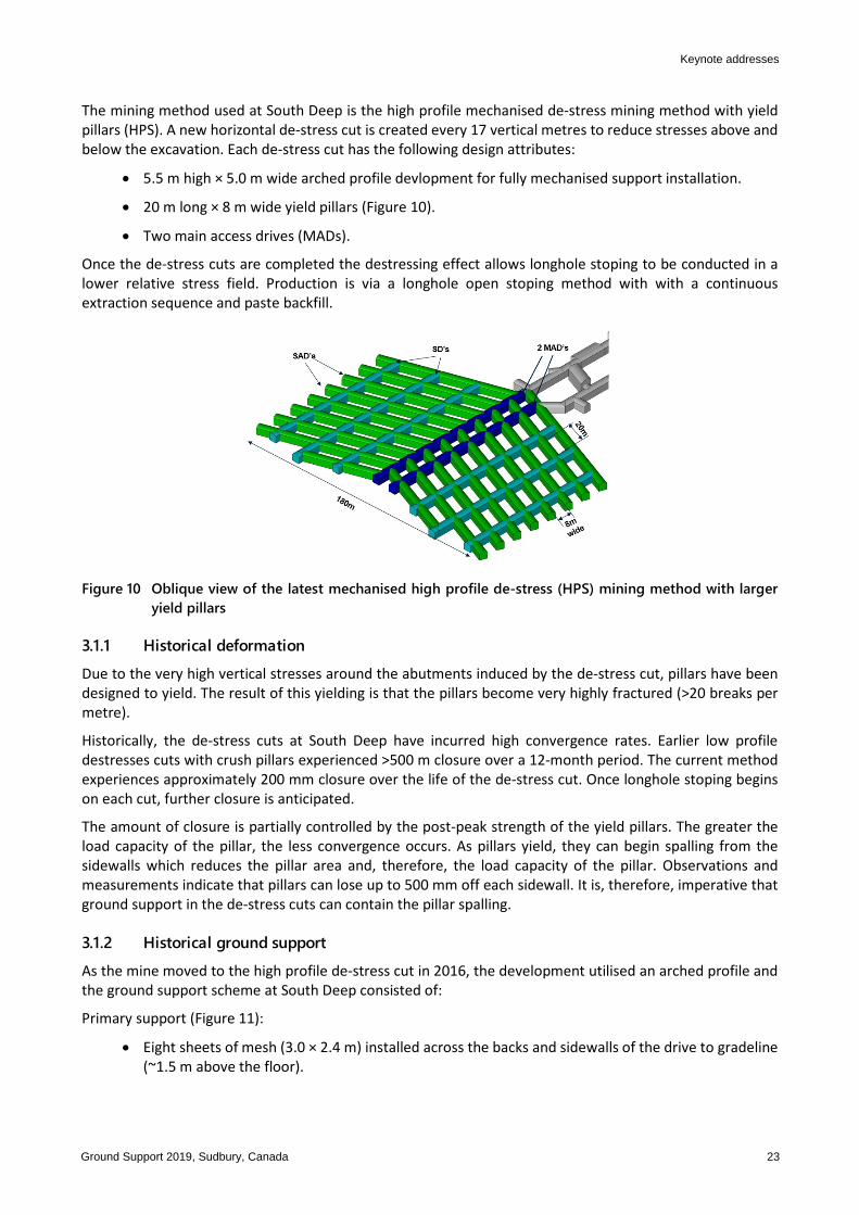
The mining method used at South Deep is the high profile mechanised de-stress mining method with yield pillars (HPS). A new horizontal de-stress cut is created every 17 vertical metres to reduce stresses above and below the excavation. Each de-stress cut has the following design attributes:
• 5.5 m high × 5.0 m wide arched profile devlopment for fully mechanised support installation.
• 20 m long × 8 m wide yield pillars (Figure 10).
• Two main access drives (MADs).
Once the de-stress cuts are completed the destressing effect allows longhole stoping to be conducted in a lower relative stress field. Production is via a longhole open stoping method with with a continuous extraction sequence and paste backfill.
Figure 10 Oblique view of the latest mechanised high profile de-stress (HPS) mining method with larger
yield pillars
3.1.1 Historical deformation Due to the very high vertical stresses around the abutments induced by the de-stress cut, pillars have been designed to yield. The result of this yielding is that the pillars become very highly fractured (>20 breaks per metre).
Historically, the de-stress cuts at South Deep have incurred high convergence rates. Earlier low profile destresses cuts with crush pillars experienced >500 m closure over a 12-month period. The current method experiences approximately 200 mm closure over the life of the de-stress cut. Once longhole stoping begins on each cut, further closure is anticipated.
The amount of closure is partially controlled by the post-peak strength of the yield pillars. The greater the load capacity of the pillar, the less convergence occurs. As pillars yield, they can begin spalling from the sidewalls which reduces the pillar area and, therefore, the load capacity of the pillar. Observations and measurements indicate that pillars can lose up to 500 mm off each sidewall. It is, therefore, imperative that ground support in the de-stress cuts can contain the pillar spalling.
3.1.2 Historical ground support As the mine moved to the high profile de-stress cut in 2016, the development utilised an arched profile and the ground support scheme at South Deep consisted of:
Primary support (Figure 11):
• Eight sheets of mesh (3.0 × 2.4 m) installed across the backs and sidewalls of the drive to gradeline (~1.5 m above the floor).
Keynote addresses
Ground Support 2019, Sudbury, Canada 23

• 33 × 2.4 m long hybrid dynamic bolts. These are the South African made version of the hybrid bolt. They were designed to begin to yield at 18 kN. A maximum designed yield of 300 mm and a dynamic load capacity of 30 kJ was claimed. These are installed on a 1.4 m collar spacing and a 1.2 m ring spacing. These are installed above the grade/mesh line and across the backs of the drive.
• Two 3.0 m long Osro straps. These were installed at the base of the mesh at gradeline.
Secondary support:
• 14 6 m long 38 t single strand cables. Installed within a three-cut (~10 m) lag from the face. These are installed on a 2.0 m collar spacing and a 2.0 m ring spacing between primary support rings.
Figure 11 Primary and secondary ground support schemes at South Deep circa 2016
3.1.3 Ground support performance and rehabilitation The primary ground support for de-stress development worked well when it was installed within 48 hours of development rounds being taken. If delays occurred, the rock mass in the pillar side walls fractured and yielded, making installation difficult.
Even when primary support was installed in time, the biggest issue with the support scheme was in retaining the fractured rock mass behind the mesh. As the sidewall support was only installed to the gradeline, as the rock mass fractured, the broken material was found to unravel below the mesh and fall to the floor. Investigations and observations on the yield pillars indicated that they have fractured across the 8 m design width.
South Deep is a seismically active mine with lots of minor events occurring around the periphery of the de-stress cut. It was found that low-magnitude events caused shakedown of the broken material behind the mesh up to a depth of ~2.0 m. It is believed that the events caused ejection of the broken rock mass. Because of this ejection, the mesh bulked out and then the bolts were then pulled out of the fractured rock allowing more fractured material to spall away (Figure 12).
Investigations of the failed bolts indicated that no dynamic yield had occurred on the anchor. Rather that failed occurred due to unravelling of the rock mass around the bolt. It was highlighted that although yielding bolts did not work, the support scheme was not able to retain the broken rock mass.
Rehabilitation has been required on approximately 70% of the yield pillars and along the sidewalls of the MADs. Over the last two years, this rehabilitation has caused delays to longhole stoping of approximately six months.
Ground support selection rationale: a Gold Fields perspective PG Andrews
24 Ground Support 2019, Sudbury, Canada

Figure 12 Ground support damage of the Garock hybrid bolts as pillars unravel around the highly fractured
rock mass
3.2 Ground support review Due to the amount of rehabilitation and damage to both the rock mass and ground support, a review of the ground support schemes was undertaken. Again, the geotechnical, mining and commercial departments all had input into the proposed support schemes.
Based on ground conditions, the new support scheme would be required to have the following features:
• The new yielding bolt required a static load of 18 kN and have a dynamical capacity of >25 kJ.
• Be installed by current fleet (jumbos and bolters).
• A new surface support element was needed to help retain the fractured rock mass.
The Vulcan Bolt, a modernised hybrid bolt being developed by New Concept Mining (NCM), was identified as a viable support solution for South Deep because it specifically addresses the pitfalls of traditional hybrid bolt systems.
The primary components of the Vulcan Bolt are the yielding bar and the friction unit (Figure 13). The bar transfers pretension into the rock mass between the end-anchoring mechanism and faceplate to provide a clamping action. The friction unit creates full column support in the borehole which is available on installation before pretension has occurred. The end-anchoring mechanism activates against the friction unit’s anchorage into the borehole. This ensures that bolt pretention and load indicator activation can only occur if the bolt is correctly installed into the borehole.
The performance of the Vulcan Bolt reinforcement system was evaluated through laboratory tests, which included static pull, dynamic drop, and torque tests), and underground tests (pull test, torque test, and quality of the installation). The performance of the bolts during seismicity was also evaluated.
For the new surface support element, fibre-reinforced shotcrete was chosen. Logistically it is difficult to get premixed bags of dry material to the heading, followed by mixing the components and spraying.
Keynote addresses
Ground Support 2019, Sudbury, Canada 25

Figure 13 Vulcan Bolt primary components
3.2.1 Bolt testing
3.2.1.1 Dynamic testing
During product development, 17 dynamic impact tests were conducted using the various host tube designs. These tests were conducted incrementally throughout the project to accommodate and verify various bolt design changes and as our understanding of each testing methodology evolved. The test samples were extensively tested in both 47 kJ single strike to failure and 17 kJ cumulative strike to failure configurations with a standardised impulse velocity of 5.2 m/s. No samples tested failed dynamically with energy absorbed over distances between 190 and 260 mm. The average absorbed energy by the bolts is 55 kJ in a grouted pipe. No underground dynamic tests were undertaken.
3.2.1.2 Underground testing
The initial in situ installations of the Ø46 mm Vulcan Bolt achieved an installation success rate of 70% with the Ø46 Vulcan Bolt averaging an installation time of three minutes and 52 seconds. Installation success rates were considered low and included problems such as incorrect support hole depth, unsuitable installation tooling, and operator unfamiliarity of the installation procedure. In the final installation trial, a complete end was supported using 33 Vulcan Bolts with an installation success rate of 94%. Total support time was approximately five minutes per bolt including drilling, bolt loading and alignment, percussive installation and pretensioning to 50 kN. Time taken to percussively drive in and tension the Vulcan Bolt averaged 27 seconds from the start of the bolt drive.
In situ pull testing of the samples was conducted and limited to a proof load of 150 kN to prevent plastic yielding of the bolt samples.
Based on results of the trials, the decision to move forward with the Vulcan Bolts was approved.
3.3 Upgraded ground support scheme Based around the Vulcan Bolts and the addition of fibrecrete, a new support scheme was developed in late 2018 and is still current today (Figure 8). The new scheme incorporated the hybrid bolt and can be described as follows:
Primary support (Figure 14):
• 50 mm of (30 MPa, 500 J) fibrecrete sprayed from floor of the footwall to the hanging wall floor for the MADs.
○ 50 mm is sprayed from the floor to 2 m above the floor in stope access drives to reduce sidewall spalling.
Ground support selection rationale: a Gold Fields perspective PG Andrews
26 Ground Support 2019, Sudbury, Canada

○ Eight sheets of mesh (3.0 × 2.4 m) installed across the backs and sidewalls of the drive to ~1.0 m above the floor.
○ 39 2.4 m long Vulcan dynamic bolts. These are installed on a 1.2 m collar spacing and a 1.1 m ring spacing. These are installed across the backs of the drive to ~1.0 m above the floor.
Secondary support:
• 14 6 m long 38 t single strand cables. Installed within a three-cut (~10 m) lag from the face. These are installed on a 2.0 m collar spacing and a 2.0 m ring spacing between primary support rings.
Figure 14 Current primary and secondary ground support schemes for MADs at South Deep
3.3.1 Results
Since the inception of the latest ground support scheme, the amount of pillar sidewall and MAD rehabilitation has reduced considerably. Recent reviews indicate that ~25% of yield pillars have required rehabilitation.
The Vulcan Bolts in conjunction with fibrecrete and mesh have been found to retain all fractured rock mass and minimise spalling of the yield pillars. Also observed was that most episodes of seismic ejection are now also retained by the support scheme (Figure 15).
Figure 15 Much improved ground conditions using the new de-stress support scheme at South Deep
Keynote addresses
Ground Support 2019, Sudbury, Canada 27

4 Conclusion The final phase of support selection is conducted both offsite and onsite and includes trials covering static and dynamic testing, installation cycle times, and ease of installation. These trials are very important in ensuring the appropriate ground support scheme is installed for the conditions.
Based on the results shown at two Gold Fields operations, it can be concluded that with the correct testing and trials of ground support prior to rolling out the scheme, significant improvements in ground performance, and a reduction in rehabilitation can be gained.
Acknowledgement The author acknowledges the Agnew and South Deep management teams for their permission in writing this paper. Further acknowledgement is given to both New Concept Mining and Garock for allowing details of test work to be presented.
References Hadjigeorgiou, J, Karampinos, E, Turcotte, P, Mercier-Langevin, F & Wilson, D 2013, Assessment of the influence of drift orientation
on observed levels of squeezing in hard rock mines, in Y Potvin & B Brady (eds), Proceedings of the Seventh International Symposium on Ground Support in Mining and Underground Construction, Australian Centre for Geomechanics, Perth, pp. 109–117.
Mercier-Langevin, F & Hadjigeorgiou, J 2011, ‘Towards a better understanding of squeezing potential in hard rock mines’, Mining Technology Journal, vol. 120, no. 1, pp. 36–44.
Moulding, CR, Stephenson, RM, Barsanti, BJ & Francis, DD 2017, ‘Managing the onset of accelerated deformation in capital development at Agnew Gold Mine’, in J Wesseloo (ed.), Proceedings of the Eighth International Conference on Deep and High Stress Mining, Australian Centre for Geomechanics, Perth, pp. 937–948.
Sandy, MP, Gibson, W & Gaudreau, D 2007, ‘Canadian and Australian ground support practices in high deformation environments’, in Y Potvin (ed.), Proceedings of the Fourth International Seminar on Deep and High Stress Mining, Australian Centre for Geomechanics, Perth, pp. 297–312.
Voyzelle, B & Anderson, T 2015, Laboratory Testing of Static and Dynamic Behaviours of Garock Hybrid Bolts, Project Report #: P-002180.001, CMIN 2015-2658-RE.
Watson, BP, Pretorius, W, Mpunzi, P, Du Plooy, M, Matthysen, K & Kuijpers, JS 2014, ‘Design and positive financial impact of crush pillars on mechanised deep-level mining at South Deep Gold Mine’, Journal of the Southern African Institute of Mining and Metallurgy, vol. 114, no. 10, pp. 863–873.
Woolley, CE & Andrews, P 2015, 'Short-term solutions to squeezing ground at Agnew Gold Mine, Western Australia', in Y Potvin (ed.), Proceedings of the International Seminar on Design Methods in Underground Mining, Australian Centre for Geomechanics, Perth, pp. 199–214.
Ground support selection rationale: a Gold Fields perspective PG Andrews
28 Ground Support 2019, Sudbury, Canada