Power Transfer Through Strongly Coupled Resonances_MIT_thesis

Ground states of strongly coupled quantum systems of light and matter
Nick RiveraMIT Physics
(in collaboration with Dr. Johannes Flick and Prof. Prineha Narang at Harvard)
The “alchemy” of the quantum vacuumQuantum ElectrodynamicsDOI: 10.1002/anie.201107033
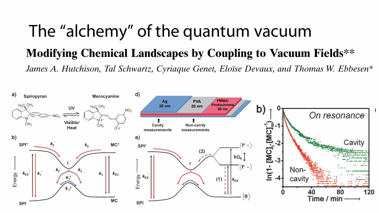
Modifying Chemical Landscapes by Coupling to Vacuum Fields**James A. Hutchison, Tal Schwartz, Cyriaque Genet, Elo!se Devaux, and Thomas W. Ebbesen*
Just as atoms exchange electrons to form molecular orbitals,an electromagnetic field can interact with a quantum systemby the exchange of photons. When this interaction is strongenough to overcome decoherence effects, new hybrid light–matter states can form, separated by what is known as theRabi splitting energy (Figure 1). This strong coupling regime
is typically achieved by placing the material in an opticalcavity, such as that formed by two parallel mirrors, which istuned to be resonant with a transition to an excited state.Theory, discussed below, shows that even in the absence oflight, a residual splitting always exists due to coupling tovacuum (electromagnetic) fields in the cavity. While cavitystrong coupling and the associated hybrid states have beenextensively studied due to the potential they offer in physicssuch as room temperature Bose–Einstein condensates andthresholdless lasers,[1–14] the implication for chemistry remainstotally unexplored. This is despite the fact that strongcoupling with organic molecules lead to exceptionally largevacuum Rabi splittings (hundreds of meV) due to their largetransition dipole moments.[15–24] The molecules plus the cavitymust thus be thought of as a single entity with new energylevels and therefore should have its own distinct chemistry.
We demonstrate here that one can indeed influence achemical reaction by strongly coupling the energy landscapegoverning the reaction pathway to vacuum fields.
In the absence of dissipation, the Rabi splitting energy !hWR (Figure 1) between the two new hybrid light–matter statesis given, for a two-level system at resonance with a cavitymode, by the product of the electric field amplitude E in thecavity and the transition dipole moment d :[13]
!hWR ¼ 2E dffiffiffiffiffiffiffiffiffiffiffiffiffiffiffinph þ 1
q¼ 2
ffiffiffiffiffiffiffiffiffiffiffi!hw
2e0V
rdffiffiffiffiffiffiffiffiffiffiffiffiffiffiffinph þ 1
qð1Þ
where !hw is the cavity resonance or transition energy, e0 thevacuum permittivity, V the mode volume and nph the numberof photons in the cavity. As can be seen, even when nph goes tozero, there remains a finite value for the Rabi splitting, !hWVRS,due to the interaction with the vacuum field. This splitting isitself proportional to the square root of the number ofmolecules in the cavity
ffiffiffiffiffiffiffiffinmolp [13, 14] which in turn implies that !h
WVRS is proportional to the square root of the concentrationffiffiffiffiffiffiffiffiffiffiffiffiffiffinmol=V
p, as observed experimentally for instance in the case
of molecules strongly coupled with surface plasmons.[21]
We chose as a model system a photochrome whichprovides one form with a transition dipole moment d tofavor strong coupling [Eq. (1)] and the associated chemicalreaction is monomolecular to avoid any complications due todiffusion. The photochromic molecule is the spiropyran (SPI)derivative 1’,3’-dihydro-1’,3’,3’-trimethyl-6-nitrospiro[2H-1-benzopyran-2,2’-(2H)-indole] which undergoes ring cleavagefollowing photoexcitation to form a merocyanine (MC)(Figure 2a). The extended conjugation of the latter resultsin strong absorption in the visible (Figure 2c, red curve). Thereverse reaction can be achieved photochemically or bythermal means. The simplified potential energy surface forthis photochrome is shown schematically in Figure 2b. Theabsorption spectrum of the SPI form in a poly(methylmeth-acrylate) (PMMA) film is shown in Figure 2c. Upon irradi-ation at 330 nm, the SPI photoisomerizes to the MC form andthe absorbance of the MC form (lmax = 560 nm, red curveFigure 2c) increases until the photostationary state isreached.
To form the resonant cavity, the PMMA film containingthe photochrome was sandwiched between two Ag mirrors,insulated from direct contact to the Ag by thin poly(vinylalcohol) (PVA) films as shown in Figure 2d. The first Agmirror was deposited on the glass substrate but note that thesecond mirror was not sputtered nor evaporated directly onthe PMMA film to avoid any possible perturbation of thechemical system. Instead the top Ag film was deposited on aseparate block of poly(dimethylsiloxane) (PDMS) which wasthen transferred to the sample, effectively encapsulating thephotochrome in the microcavity (see Supporting Information
Figure 1. Simplified energy landscape showing the interaction of aHOMO–LUMO (S0–S1) transition of a molecule resonant with a cavitymode !hwc. When energy exchange between the molecular transitionand the cavity is rapid compared to energy loss, strong coupling leadsto the formation of two hybrid light–matter (polaritonic) states jP +iand jP%i, separated by the Rabi splitting energy !hWR. Note that theabsolute energy of the ground level of the coupled system j0i mayalso be modified by strong coupling.
[*] Dr. J. A. Hutchison,[+] Dr. T. Schwartz,[+] Dr. C. Genet, Dr. E. Devaux,Prof. T. W. EbbesenISIS, Universit! de Strasbourg and CNRS (UMR 7006)Strasbourg (France)E-mail: [email protected]
[+] These authors contributed equally to this work.
[**] This research was supported by the ERC (grant no. 227577).
Supporting information for this article is available on the WWWunder http://dx.doi.org/10.1002/anie.201107033.
.AngewandteCommunications
1592 ! 2012 Wiley-VCH Verlag GmbH & Co. KGaA, Weinheim Angew. Chem. Int. Ed. 2012, 51, 1592 –1596
for details). The transmission spectrum of this cavity structureis characterized by two features: a peak at 326 nm due to thetransparency window of silver corresponding to its plasmafrequency, and the fundamental Fabry–Perot cavity mode,which for a total PVA/PMMA/PVA thickness of 130 nmoccurs at 560 nm (these cavity transmission features can beseen in Figure 3a, black curve).[24] The Fabry–Perot mode istherefore resonant with the absorption of MC. UV irradiationof the cavity at 330 nm causes formation of MC just as for thecase of the isolated PMMA film.
When the MC is strongly coupled to the vacuum field inthe cavity, the resulting formation of the hybrid states (orpolaritons) is evidenced by the splitting of the absorption intotwo new peaks (green curve Figure 2 f). The detailed physicsof the strong coupling of this particular system have beenpresented elsewhere.[24] In brief, at the photostationary state,ca. 80 % of the MC species are strongly coupled and the
vacuum Rabi splitting is in theorder of 700 meV (Figure 2 f).In other words, the new hybridstates, jP +i and jP!i, haveabsorptions at " 350 meV rel-ative to the transition energyof the uncoupled MC(2.2 eV). Note that this Rabisplitting does not arise fromthe photons used to probe thesystem but is only due to thevacuum field as can be seenfrom the fact that the spec-trum of the coupled moleculesis independent of the weaklight intensity used to recordit.
We now analyze the pho-toisomerization kineticsinside and outside the cavity.The detailed photoisomeriza-tion mechanism, schemati-cally simplified in Figure 2b,is still in debate in the liter-ature due to its complexityand is reported to involveseveral intermediate isomers,including the triplet manifold,here collectively shown as asingle species I.[25–29] Never-theless the reaction proceedswith observed first-orderkinetics in solution. An over-all first-order reaction mecha-nism (kobs) is also predictedfrom the simplified reactiondiagram in Figure 2b wherekobs is a complex function ofthe quantum yields of thevarious individual photoin-duced steps:
d½MC$dt ¼ !kobs½MC$ þ b
with kobs ¼k03
k3 þ k03k2
k1 þ k2þ k3
k3 þ k03k02
k01 þ k02
! "kex
and b ¼ k3
k3 þ k03k02
k01 þ k02kex½SPI$0
ð2Þ
The detailed derivation of this rate equation is given in theSupporting Information. It assumes that the intermediatesSPI*, I and MC* are in a stationary state and it is simplified byirradiation at the isosbestic point for the two species at330 nm. The photostationary (PS) concentration ratio underthe experimental conditions for this model is given by:
½MC$PS
½SPI$PS¼ k3k02
k03 k01 þ k02ð Þ 1þ k1
k2
! "ð3Þ
Figure 2. a) The molecular structure of spiropyran (SPI) and merocyanine (MC). b) Diagram of the energylandscape connecting the two isomers in the ground and first excited state where kEX and kEX’ are the ratesof photoexcitation and the others the rates of the internal pathways; for example, k1 represents the sum ofnon-radiative and radiative relaxation rates from MC* to MC. Vibrational sub-levels are not included forclarity. c) The ground state absorption spectra of SPI (black) and MC (red) in PMMA film. d) The structureof the cavity; note that cavity and non-coupled measurements were done concurrently on the same film.e) Diagram of the energy landscape connecting the two isomers in the ground and first excited state, withmodification of the MC states by strong coupling and the appearance of the polariton states jP +i andjP!i, separated by the Rabi splitting !hWR. f) The ground state absorption spectra of SPI (black) in PMMAand of the coupled system (green, structure shown in (d)) determined experimentally in the availablewavelength window by measuring the transmission T and reflection R of the sample (Abs = 1!T!R).
AngewandteChemie
1593Angew. Chem. Int. Ed. 2012, 51, 1592 –1596 ! 2012 Wiley-VCH Verlag GmbH & Co. KGaA, Weinheim www.angewandte.org
In a polymer matrix, the internal isomerization processesare further complicated by convolution with the heteroge-neous segmental motion of the polymer resulting in devia-tions from exponential behavior.[29] The kinetic build-up ofMC in the PMMA matrix (outside the cavity) during UVirradiation at 330 nm shows indeed deviation from linearitywhen plotted on a log scale (red points in Figure 3b). Shownin Figure 3a is the progression of the same reaction, but insidethe cavity, monitored by transmission spectra of the cavitystructure. The Fabry–Perot mode is reduced and splits as theMC concentration increases. Using transfer matrix simula-tions, the transmission spectra as a function of time allow us tocalculate the absorbance of MC at each time. This data issuperimposed on that of the bare molecular film in Figure 3b,making a slight correction for the different intensities of330 nm light impinging on the polymer layer for the openstructure and for the cavity (around 20 % higher in the lattercase). It is clear (Figure 3b) that while the rates measured forthe two systems are similar at early times, as the reactionproceeds, the observed photoisomerization rate is sloweddown significantly in the cavity structure. This retardationcorresponds to the onset of strong-coupling conditions and
the formation of the hybrid light–matter states. The larger thesplitting, the slower is the overall reaction reaching a fractionof the initial rate. We stress that the intensity of the UV lightpenetrating the cavity remains constant, which is ensured bythe invariance of the spectrum around 330 nm. Hence, thechange in rate cannot be attributed to a simple optical effect.The final concentrations of the species at the photostationarystate are also modified, increasing the MC yield in the cavityby ca. 10 %. Furthermore, it was checked that when the cavityis designed in such a way to be out of resonance (at all angles)with the MC absorption transition, there is no change in rate(Figure 3c) compared to the film outside the cavity.
A slowing of SPI-MC photoisomerization as the systementers strong-coupling conditions is fully consistent with thechange in energy landscape in Figure 2e and Equation (2).The upper lying jP +i state will rapidly decay to jP!i whichin turn by lying lower than the uncoupled excited state MC*will favor the return to ground state (path (1) over path (2) inFigure 2e). The corresponding change in the rate constants k1
and k2 would result in a reduction in kobs for the photo-isomerization (through the decrease of the k2/(k1+k2) term inEquation (2)) and an increase in the photostationary concen-tration of coupled MC [k1/k2 increases in Eq. (3)], as isobserved.
While the modification of the reaction potential by strongcoupling shown in Figure 1 and 2 emphasizes the splitting ofthe excited-state energy levels, one must bear in mind that thismodification will be “felt” through the entire system,reordering the energy levels including possibly the groundstate. If that is the case, the formation of the light–matterhybrid state might not only alter the photoisomerization ratesbetween SPI and MC, but also the thermal conversion of MCto SPI in the ground-state energy landscape. Theoreticalconsiderations of such ultra-strong coupling regime (intowhich this cavity/photochrome system falls)[24] also predict amodification of the ground-state energy.[11, 12] Nevertheless,careful analysis of the thermal back reaction did not revealany change in the rate beyond experimental error.
To gain further insight into the photochemical events,transient differential absorption spectroscopy (pump–probe)experiments were carried out on the coupled system andcompared to that of the uncoupled molecules. This techniquehas the advantage of probing the excited states by detectingvery small absorbance changes with minimal perturbation ofthe system, with the ability to also detect non-radiative decayprocesses in contrast to time-resolved fluorescence. Figure 4ashows the transient spectra immediately after the 150 fs pumppulse (560 nm) for different coupling strengths. As can beseen, the transient spectra are all very different from that ofthe uncoupled molecules. To understand these spectra, it isworth remembering that the transient differential absorptionDA(l) is given by Equation (4):[30]
DAðlÞ ¼ ½s*ðlÞ!s0ðlÞ!sSEðlÞ&kd½MC*& ð4Þ
where s*(l) is the excited-state absorption cross-section incm!2, s0(l) the ground-state absorption cross-section, sSE(l)the stimulated-emission cross-section of the excited state, kthe constant that relates the molar extinction coefficient to
Figure 3. a) Transmission spectrum of the coupled system in the cavityas a function of irradiation time at 330 nm where the Ag film has atransparency window as seen in the spectra. Notice that the initialFabry–Perot mode at ca. 560 nm (black curve) splits into two newmodes as the SPI to MC photoreaction proceeds. b) Kinetics of thegrowth of the MC absorbance (i.e. concentration) measured for thebare molecules (red) and the coupled system (green) in the config-uration shown in Figure 2d; in other words, the uncoupled moleculeswere irradiated through one mirror on the same sample as the cavitysystem involving two mirrors. The negative log plot stems from takingln(1![MC]t/[MC]1) versus t. For this case, in which the cavityresonance is tuned to exactly match the MC absorption at 560 nm, thedifference in the rates increases with the degree of strong coupling.c) In contrast, when the cavity thickness is tuned such that it is non-resonant with the MC absorption for all angles of incidence, thephotoisomerization rate is identical to that of the non-cavity sample.
.AngewandteCommunications
1594 www.angewandte.org ! 2012 Wiley-VCH Verlag GmbH & Co. KGaA, Weinheim Angew. Chem. Int. Ed. 2012, 51, 1592 –1596
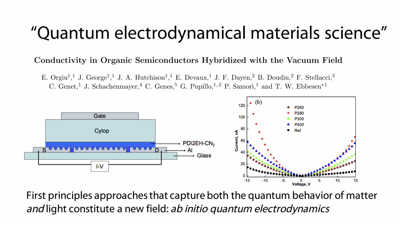
“Quantum electrodynamical materials science”
First principles approaches that capture both the quantum behavior of matter and light constitute a new field: ab initio quantum electrodynamics
Conductivity in Organic Semiconductors Hybridized with the Vacuum Field
E. Orgiu†,1 J. George†,1 J. A. Hutchison†,1 E. Devaux,1 J. F. Dayen,2 B. Doudin,2 F. Stellacci,3
C. Genet,1 J. Schachenmayer,4 C. Genes,5 G. Pupillo,1, 2 P. Samorı,1 and T. W. Ebbesen⇤1
1ISIS & icFRC, Universite de Strasbourg and CNRS, 67000 Strasbourg, France2IPCMS & icFRC, Universite de Strasbourg and CNRS, 67034 Strasbourg, France
3EPFL, STI SMX-GE MXG 030 Station 12, CH-1015 Lausanne, Switzerland4JILA, NIST, Department of Physics, University of Colorado, 440 UCB, Boulder, CO 80309, USA
5Institut fur Theoretische Physik, Universitat Innsbruck, Technikerstrasse 25, A-6020 Innsbruck, Austria(Dated: May 27, 2015)
Organic semiconductors have generated considerable interest for their potential for creating inex-pensive and flexible devices easily processed on a large scale [1–11]. However technological applica-tions are currently limited by the low mobility of the charge carriers associated with the disorder inthese materials [5–8]. Much e↵ort over the past decades has therefore been focused on optimizingthe organisation of the material or the devices to improve carrier mobility. Here we take a radicallydi↵erent path to solving this problem, namely by injecting carriers into states that are hybridizedto the vacuum electromagnetic field. These are coherent states that can extend over as many as105 molecules and should thereby favour conductivity in such materials. To test this idea, organicsemiconductors were strongly coupled to the vacuum electromagnetic field on plasmonic structuresto form polaritonic states with large Rabi splittings ⇠ 0.7 eV. Conductivity experiments show thatindeed the current does increase by an order of magnitude at resonance in the coupled state, reflect-ing mostly a change in field-e↵ect mobility as revealed when the structure is gated in a transistorconfiguration. A theoretical quantum model is presented that confirms the delocalization of thewave-functions of the hybridized states and the consequences on the conductivity. While this isa proof-of-principle study, in practice conductivity mediated by light-matter hybridized states iseasy to implement and we therefore expect that it will be used to improve organic devices. Morebroadly our findings illustrate the potential of engineering the vacuum electromagnetic environmentto modify and to improve properties of materials.
Light and matter can enter into the strong couplingregime by exchanging photons faster than any compet-ing dissipation processes. This is normally achieved byplacing the material in a confined electromagnetic envi-ronment, such as a Fabry-Perot (FP) cavity composed oftwo parallel mirrors that is resonant with an electronictransition in the material. Alternatively, one can use sur-face plasmon resonances as in this study. Strong couplingleads to the formation of two hybridized light-matter po-laritonic states, P+ and P-, separated by the so-calledRabi splitting, as illustrated in Figure 1a. According toquantum electrodynamics, in the absence of dissipation,the Rabi splitting for a single molecule is given by
~⌦R = 2
r
~!2✏0v
· d ·p
nph + 1 (1)
where ~! is the cavity resonance or transition energy (~the reduced Planck constant), ✏0 the vacuum permittiv-ity, v the mode volume, d the transition dipole momentof the material and nph the number of photons presentin the system. The last term implies that, even in thedark, the Rabi splitting has a finite value which is dueto the interaction with the vacuum electromagnetic field.This vacuum Rabi splitting can be further increased bycoupling a large number N of oscillators to the electro-magnetic mode since ~⌦N
R /pN [12]. In this ensemble
coupling, in addition to P+ and P-, there are many othercombinations of states, known as dark states [13], that
are located in the middle of the Rabi splitting as illus-trated in Fig. 1a.
Polaritons have been extensively studied in inorganicand organic materials [14–36]. Vacuum Rabi splittingsas large as 1 eV have been reported for strongly cou-pled molecules [17, 18], thereby significantly modifyingthe electronic structure of the molecular material as canbe seen in the work function, the ground state energyshift as well as in the chemical reactivity [20–22]. Insuch situations, P+ and P- are coherent collective states(Fig. 1b) that extend over the mode volume and may in-volve ⇠ 105 oscillators as in the present systems. Thiscollective nature has been demonstrated by the coherentfluorescence of P- over micrometers distances in stronglycoupled molecular states [23, 24]. Charge carrier mo-bility should also benefit from the extended coherenceassociated with light-hybridized states as compared tothe normal carrier mobilities limited by the hopping be-tween molecules and by scattering induced by moleculardisorder.
While electron injected polariton LEDs and lasers havebeen reported in the last years [31–37], conductivity me-diated by light-hybridized materials has not been consid-ered. One of the challenges in those studies has been toinject electrons into P+ or P- since these states have notjust well defined energies but also momenta associatedwith their dispersion curves. In this regard, molecularmaterials have the advantage that the energies of the
arX
iv:1
409.
1900
v2 [
cond
-mat
.mtrl
-sci
] 26
May
201
5
12
FIG. 3: Conductivity under strong coupling on Al arrays and Gating. (a) Spectra of Al hole array with and withoutPDI2EH-CN2 as shown; (b) I-V curves for selected periods versus reference in the same geometry as in Fig. 2a. (c) Threeterminal gating device geometry. It is composed of: Al (40 nm) acting as a top gate; ⇠ 600 nm of Cytop, a polymer dielectricacting as a gate insulator ("r = 2.1); 100 nm of PDI2EH-CN2 as the semiconductor layer; Al electrodes and nanohole arraystructure. [W = 50 µm, L = 50 µm]. Note that the surface plasmon modes is only slightly modified by the presence ofthe dielectric as most of the evanescent plasmonic field is confined within the organic semiconductor layer. Typical transfercharacteristics (ID � VG) of top-gate bottom-contact FETs realized on the structure proposed in Figure 3c. In particular thegraph shows the di↵erence between a gated structure with hole arrays of periodicity P = 280 nm (d) vs. a reference (e) structurewith the same geometry but without nanohole arrays. The ratio of the mobilities is µFET[P=280nm]/µFET[reference] ⇠ 10 whichcorresponds essentially to the ratio of the current measured in the I-V curves.
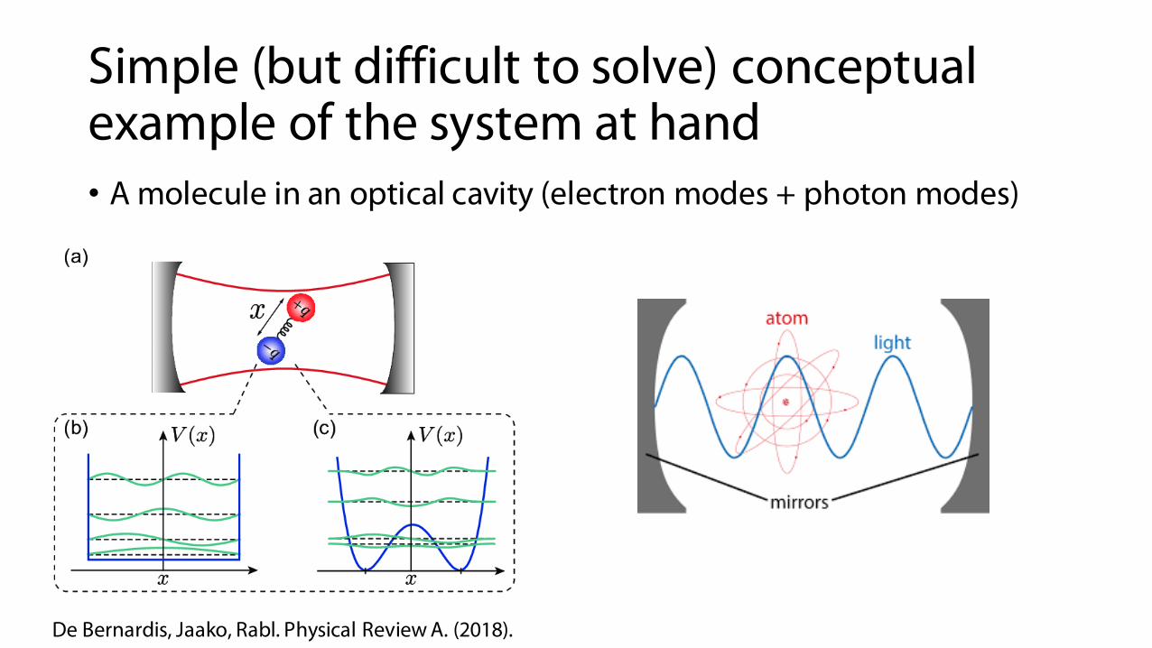
Simple (but difficult to solve) conceptual example of the system at hand• A molecule in an optical cavity (electron modes + photon modes)
De Bernardis, Jaako, Rabl. Physical Review A. (2018).
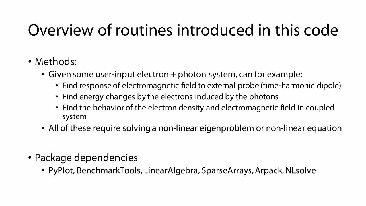
Overview of routines introduced in this code
• Methods:• Given some user-input electron + photon system, can for example:
• Find response of electromagnetic field to external probe (time-harmonic dipole)• Find energy changes by the electrons induced by the photons• Find the behavior of the electron density and electromagnetic field in coupled
system• All of these require solving a non-linear eigenproblem or non-linear equation
• Package dependencies• PyPlot, BenchmarkTools, LinearAlgebra, SparseArrays, Arpack, NLsolve
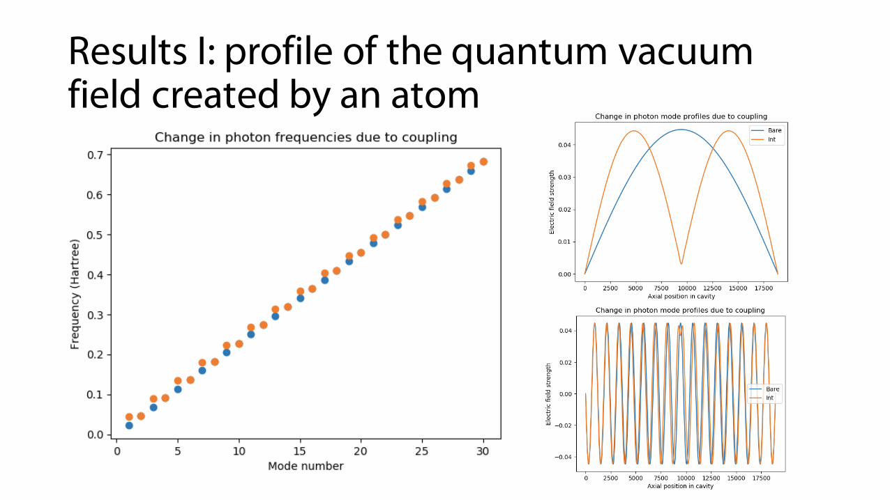
Results I: profile of the quantum vacuum field created by an atom
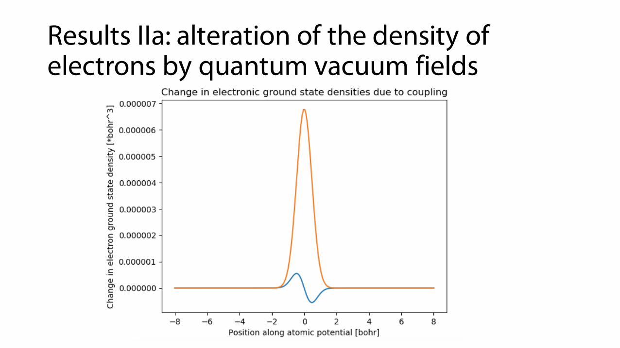
Results IIa: alteration of the density of electrons by quantum vacuum fields
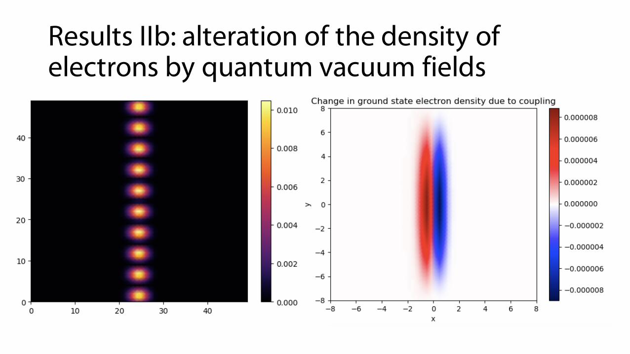
Results IIb: alteration of the density of electrons by quantum vacuum fields
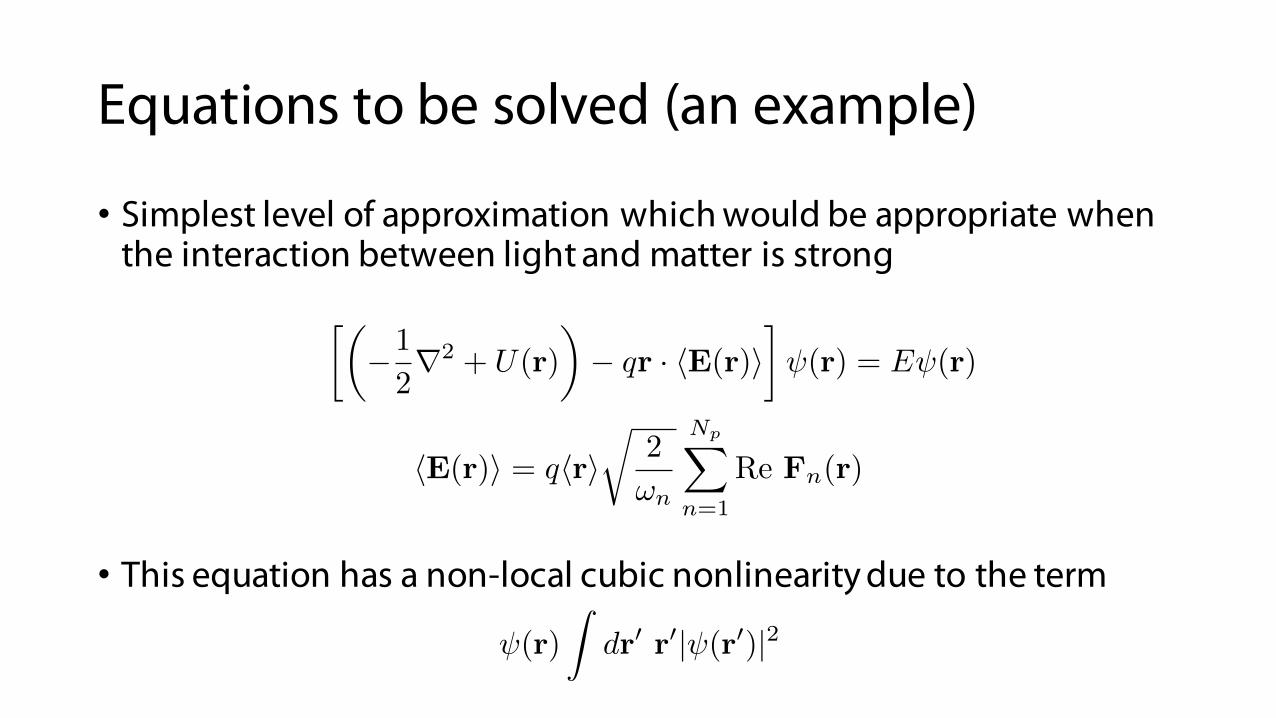
Equations to be solved (an example)
• Simplest level of approximation which would be appropriate when the interaction between light and matter is strong
• This equation has a non-local cubic nonlinearity due to the term
✓�1
2r2 + U(r)
◆� qr · hE(r)i
� (r) = E (r)
hE(r)i = qhrir
2
!n
NpX
n=1
Re Fn(r)
(r)
Zdr0 r0| (r0)|2

julia NLsolve package is a highly flexible method for solving fixed point problems• Often good way to solve a non-linear equation: cast it into the form F(x) = x
• At kth step: is linear. Solved when
• NLsolve in julia provides a general framework for solving these problems.
u00 + au3 = �u
u00k + au2
k�1uk = �kuk
f(uk�1) = eigs(D2 + au2k�1) ⇡ uk�1
can be an eigensolver (as in the code I wrote)

julia NLsolve package as a highly flexible method for solving fixed point problems
m = 0: Picard iteration
m != 0: Anderson acceleration
eigensolver which takesphotons, constructs effectivepotential felt by electrons, anddiagonalizes

julia: easily exploit structure through types makes it easy to interface with other software and easy to write common code to different methods
Gives opportunity to “feed in”results from generic quantumeigensolvers and Maxwell eigensolverslike MPB, COMSOL, etc.