Ground settlement during tunneling in groundwater drawdown ...
10
Ground settlement during tunneling in groundwater drawdown environment – Influencing factors Chungsik Yoo ⇑ School of Civil, Architectural Engineering and Landscape Architecture, Sungkyunkwan University, 2066 Seoboo Ro, Jan-An Gu, Suwon, Kyong-Gi Do 16419, Republic of Korea Received 1 June 2016; received in revised form 9 July 2016; accepted 25 July 2016 Available online 10 August 2016 Abstract In this paper, the results of a parametric study on groundwater drawdown-induced surface settlement during tunneling in water- bearing ground are presented. A calibrated stress–pore pressure coupled finite element model was adopted for the parametric analysis. The results were analyzed to establish the relationships between key design issues, such as the ground surface settlement and groundwater drawdown, and influencing factors. An artificial neural network (ANN)-based sensitivity analysis was performed to obtain insight into the relative importance of the influencing factors. The results indicated that the primary influencing factors on the settlement develop- ment are the thickness and stiffness of the soil layer within the drawdown zone and the lining permeability, while the initial void ratio and the permeability of the soil layer were considered secondary influencing factors. Practical implications and findings of the study are discussed. Ó 2016 Tongji University and Tongji University Press. Production and hosting by Elsevier B.V. on behalf of Owner. This is an open access article under the CC BY-NC-ND license (http://creativecommons.org/licenses/by-nc-nd/4.0/). Keywords: Conventional tunneling; Ground settlement; Groundwater; Finite element method; Stress–pore pressure coupled analysis 1. Introduction Tunneling activity in water-bearing ground may result in unwanted groundwater inflow into the excavated area, thus causing some groundwater drawdown. Tunneling-induced groundwater drawdown has been known to induce associ- ated ground settlements in addition to the settlements caused by the unloading effect due to excavation (Yoo, 2005; Yoo & Kim, 2006). The related ground subsidence that occurs as a result of the reduction in water pressure in the soil layers can damage nearby structures or utilities (Fig. 1). One of the major case studies concerning excessive ground surface settlements during tunneling is the Romeriksporten tunnel construction in Norway, where more than 1 m of ground subsidence occurred due to groundwater drawdown during the construction of a high-speed railway tunnel. This caused significant technical and political issues pertaining to the effect of tunneling on the surrounding environment (NSERA, 1995). Another significant case study was reported by Yoo, Lee, Kim, and Kim (2012) in which conventional tunneling in water-bearing permeable ground under an airport in oper- ation caused excessive ground surface settlements on the apron area due to inadequate groundwater control. Fig. 2 (a) shows a typical tunnel cross-section with the support pattern that was implemented. Although pre-grouting was implemented by creating a 5-m-thick watertight shell around the tunnel periphery for sections in which the weathered soil layer extended to the tunnel crown level, sig- nificant ground drawdown, as much as 25 m, occurred (Fig. 2(b)). The groundwater drawdown caused nearly 200 mm of excessive surface settlements as shown in Fig. 2(c). Details of the case study can be found in Yoo http://dx.doi.org/10.1016/j.undsp.2016.07.002 2467-9674/Ó 2016 Tongji University and Tongji University Press. Production and hosting by Elsevier B.V. on behalf of Owner. This is an open access article under the CC BY-NC-ND license (http://creativecommons.org/licenses/by-nc-nd/4.0/). ⇑ Fax: +82 31 290 7549. E-mail address: [email protected] Peer review under responsibility of Tongji University and Tongji University Press. www.elsevier.com/locate/undsp Available online at www.sciencedirect.com ScienceDirect Underground Space 1 (2016) 20–29
Transcript of Ground settlement during tunneling in groundwater drawdown ...

Available online at www.sciencedirect.com
www.elsevier.com/locate/undsp
ScienceDirect
Underground Space 1 (2016) 20–29
Ground settlement during tunneling in groundwaterdrawdown environment – Influencing factors
Chungsik Yoo ⇑
School of Civil, Architectural Engineering and Landscape Architecture, Sungkyunkwan University, 2066 Seoboo Ro, Jan-An Gu, Suwon,
Kyong-Gi Do 16419, Republic of Korea
Received 1 June 2016; received in revised form 9 July 2016; accepted 25 July 2016Available online 10 August 2016
Abstract
In this paper, the results of a parametric study on groundwater drawdown-induced surface settlement during tunneling in water-bearing ground are presented. A calibrated stress–pore pressure coupled finite element model was adopted for the parametric analysis.The results were analyzed to establish the relationships between key design issues, such as the ground surface settlement and groundwaterdrawdown, and influencing factors. An artificial neural network (ANN)-based sensitivity analysis was performed to obtain insight intothe relative importance of the influencing factors. The results indicated that the primary influencing factors on the settlement develop-ment are the thickness and stiffness of the soil layer within the drawdown zone and the lining permeability, while the initial void ratio andthe permeability of the soil layer were considered secondary influencing factors. Practical implications and findings of the study arediscussed.� 2016 Tongji University and Tongji University Press. Production and hosting by Elsevier B.V. on behalf of Owner. This is an open access articleunder the CC BY-NC-ND license (http://creativecommons.org/licenses/by-nc-nd/4.0/).
Keywords: Conventional tunneling; Ground settlement; Groundwater; Finite element method; Stress–pore pressure coupled analysis
1. Introduction
Tunneling activity in water-bearing ground may result inunwanted groundwater inflow into the excavated area, thuscausing some groundwater drawdown. Tunneling-inducedgroundwater drawdown has been known to induce associ-ated ground settlements in addition to the settlements causedby the unloading effect due to excavation (Yoo, 2005; Yoo&Kim, 2006). The related ground subsidence that occurs as aresult of the reduction in water pressure in the soil layerscan damage nearby structures or utilities (Fig. 1).
One of the major case studies concerning excessiveground surface settlements during tunneling is theRomeriksporten tunnel construction in Norway, where
http://dx.doi.org/10.1016/j.undsp.2016.07.002
2467-9674/� 2016 Tongji University and Tongji University Press. Production
This is an open access article under the CC BY-NC-ND license (http://creativec
⇑ Fax: +82 31 290 7549.E-mail address: [email protected]
Peer review under responsibility of Tongji University and TongjiUniversity Press.
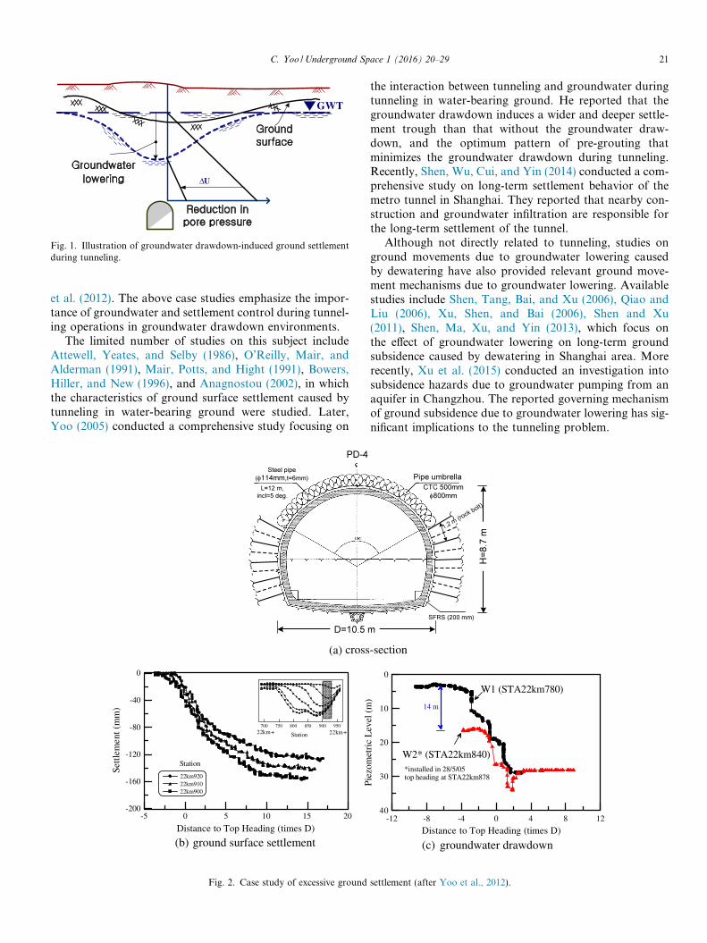
more than 1 m of ground subsidence occurred due togroundwater drawdown during the construction of ahigh-speed railway tunnel. This caused significant technicaland political issues pertaining to the effect of tunneling onthe surrounding environment (NSERA, 1995). Anothersignificant case study was reported by Yoo, Lee, Kim,and Kim (2012) in which conventional tunneling inwater-bearing permeable ground under an airport in oper-ation caused excessive ground surface settlements on theapron area due to inadequate groundwater control. Fig. 2(a) shows a typical tunnel cross-section with the supportpattern that was implemented. Although pre-groutingwas implemented by creating a 5-m-thick watertight shellaround the tunnel periphery for sections in which theweathered soil layer extended to the tunnel crown level, sig-nificant ground drawdown, as much as 25 m, occurred(Fig. 2(b)). The groundwater drawdown caused nearly200 mm of excessive surface settlements as shown inFig. 2(c). Details of the case study can be found in Yoo
and hosting by Elsevier B.V. on behalf of Owner.
ommons.org/licenses/by-nc-nd/4.0/).
Δ U
GWT
Fig. 1. Illustration of groundwater drawdown-induced ground settlementduring tunneling.
C. Yoo /Underground Space 1 (2016) 20–29 21
et al. (2012). The above case studies emphasize the impor-tance of groundwater and settlement control during tunnel-ing operations in groundwater drawdown environments.
The limited number of studies on this subject includeAttewell, Yeates, and Selby (1986), O’Reilly, Mair, andAlderman (1991), Mair, Potts, and Hight (1991), Bowers,Hiller, and New (1996), and Anagnostou (2002), in whichthe characteristics of ground surface settlement caused bytunneling in water-bearing ground were studied. Later,Yoo (2005) conducted a comprehensive study focusing on
(a) cross
Distance to Top Heading (times D)
-200
-160
-120
-80
-40
0
Settl
emen
t (m
m)
22km92022km91022km900
Station
700 750 800 850 900 950
Station22km+ 22km+
-5 0 5 10 15 20
(b) ground surface settlement
Fig. 2. Case study of excessive ground
the interaction between tunneling and groundwater duringtunneling in water-bearing ground. He reported that thegroundwater drawdown induces a wider and deeper settle-ment trough than that without the groundwater draw-down, and the optimum pattern of pre-grouting thatminimizes the groundwater drawdown during tunneling.Recently, Shen, Wu, Cui, and Yin (2014) conducted a com-prehensive study on long-term settlement behavior of themetro tunnel in Shanghai. They reported that nearby con-struction and groundwater infiltration are responsible forthe long-term settlement of the tunnel.
Although not directly related to tunneling, studies onground movements due to groundwater lowering causedby dewatering have also provided relevant ground move-ment mechanisms due to groundwater lowering. Availablestudies include Shen, Tang, Bai, and Xu (2006), Qiao andLiu (2006), Xu, Shen, and Bai (2006), Shen and Xu(2011), Shen, Ma, Xu, and Yin (2013), which focus onthe effect of groundwater lowering on long-term groundsubsidence caused by dewatering in Shanghai area. Morerecently, Xu et al. (2015) conducted an investigation intosubsidence hazards due to groundwater pumping from anaquifer in Changzhou. The reported governing mechanismof ground subsidence due to groundwater lowering has sig-nificant implications to the tunneling problem.
-section
-12 -8 -4 0 4 8 12
Distance to Top Heading (times D)
40
30
20
10
0
Piez
omet
ric
Lev
el (
m)
*installed in 28/5/05top heading at STA22km878
14 m
W1 (STA22km780)
W2* (STA22km840)
(c) groundwater drawdown
settlement (after Yoo et al., 2012).
22 C. Yoo /Underground Space 1 (2016) 20–29
The aforementioned studies have provided insight intothe governing mechanism relevant to groundwaterdrawdown-induced ground settlement during tunneling.Further in-depth studies are necessary to develop more effi-cient and robust measures for control of groundwaterdrawdown and associated ground settlement during tun-neling in water-bearing ground.
In this study, the results of a parametric study on ground-water drawdown-induced surface settlement during anurban tunneling situation are presented. Numerous tunnel-ing cases were developed for consideration of the Seoulmetro extension design project, in which the control ofground settlements associated tunneling-induced ground-water drawdown was a primary design issue. A parametricanalysis was performed on the developed tunneling casesto create a database using a calibrated stress–pore pressurecoupled finite element model which can simulate the tunnel-ing and groundwater interaction. An artificial neural net-work (ANN) based sensitivity analysis was performed toprovide insight into the relative importance of the influenc-ing factors.
The results indicated that the primary influencing factorson the settlement development are the thickness, stiffness ofthe soil layer within the drawdown zone, and the lining per-meability. The initial void ratio and the permeability of thesoil layer are found out to be secondary influencing factors.Strategies that minimize the inflow quantity are therefore ofprime importance in limiting the ground surface settlementduring tunneling in water-bearing ground. The followingsections present the tunneling cases considered, the 2D
tsH
8.5 m5 m
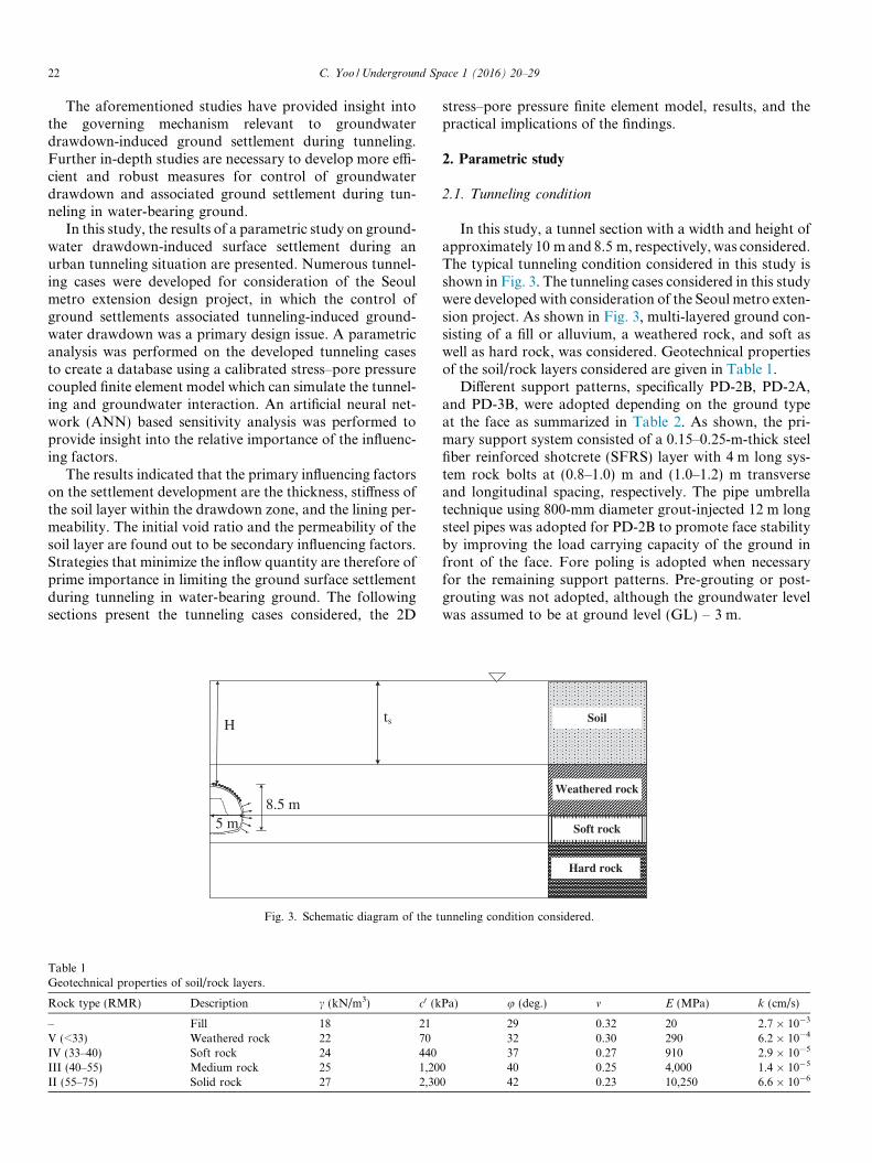
Fig. 3. Schematic diagram of the t
Table 1Geotechnical properties of soil/rock layers.
Rock type (RMR) Description c (kN/m3) c0 (k
– Fill 18 21V (<33) Weathered rock 22 70IV (33–40) Soft rock 24 440III (40–55) Medium rock 25 1,20II (55–75) Solid rock 27 2,30
stress–pore pressure finite element model, results, and thepractical implications of the findings.
2. Parametric study
2.1. Tunneling condition
In this study, a tunnel section with a width and height ofapproximately 10 m and 8.5 m, respectively, was considered.The typical tunneling condition considered in this study isshown in Fig. 3. The tunneling cases considered in this studywere developed with consideration of the Seoul metro exten-sion project. As shown in Fig. 3, multi-layered ground con-sisting of a fill or alluvium, a weathered rock, and soft aswell as hard rock, was considered. Geotechnical propertiesof the soil/rock layers considered are given in Table 1.
Different support patterns, specifically PD-2B, PD-2A,and PD-3B, were adopted depending on the ground typeat the face as summarized in Table 2. As shown, the pri-mary support system consisted of a 0.15–0.25-m-thick steelfiber reinforced shotcrete (SFRS) layer with 4 m long sys-tem rock bolts at (0.8–1.0) m and (1.0–1.2) m transverseand longitudinal spacing, respectively. The pipe umbrellatechnique using 800-mm diameter grout-injected 12 m longsteel pipes was adopted for PD-2B to promote face stabilityby improving the load carrying capacity of the ground infront of the face. Fore poling is adopted when necessaryfor the remaining support patterns. Pre-grouting or post-grouting was not adopted, although the groundwater levelwas assumed to be at ground level (GL) – 3 m.
Soil
Weathered rock
Soft rock
Hard rock
unneling condition considered.
Pa) u (deg.) m E (MPa) k (cm/s)
29 0.32 20 2.7 � 10�3
32 0.30 290 6.2 � 10�4
37 0.27 910 2.9 � 10�5
0 40 0.25 4,000 1.4 � 10�5
0 42 0.23 10,250 6.6 � 10�6

Table 2Summary of support patterns used.
Support pattern PD-2B PD-3A PD-3B
Cross-section
Ground type 0.5D above crown Weathered soil Weathered rock Weathered rockFace Weathered rock Weathered rock Soft rock
Excavation method Ring-cut Bench-cut Bench-cutUnit advancement (m) 0.8 1.0 1.0Shot’c Type Steel fiber reinforced
Thickness (mm) 250 (50 + 100 + 100) 250 (50 + 100 + 100) 200(50 + 100 + 50)Rock bolt Length (m) 4.0 4.0 4.0
Spacing trans/long (m) 0.8/1.0 1.0/1.2 1.0/1.2Steel support Type H-125 H-125 LG-70Con’c lining Thickness (mm) 400 400 400Auxiliary method Umbrella method Fore poling Fore poling
Table 3Cases considered in the parametric study.
Cover depth (H) Rock type Thickness of soil (ts) Void ratio of soil layer Permeability of Shot’c kshot (cm/s)
3D II 1.5D 0.7/1.0/1.4 2 � 10�5/2 � 10�6/2 � 10�7
III 1.0D/1.5D 0.7/1.0/1.4 2 � 10�5/2 � 10�6/2 � 10�7
IV 0.5D/1.0D/1.5D 0.7/1.0/1.4 2 � 10�5/2 � 10�6/2 � 10�7
5D II 3.0D 1.0 2 � 10�5/2 � 10�6/2 � 10�7
III 2.0D/3.0D 1.0 2 � 10�5/2 � 10�6/2 � 10�7
IV 1.0D/2.0D/3.0D 1.0 2 � 10�5/2 � 10�6
7D II 3.0D 0.7/1.0/1.4 2 � 10�5/2 � 10�6/2 � 10�7
III 2.0D/3.0D 0.7/1.0/1.4 2 � 10�5/2 � 10�6/2 � 10�7
IV 1.0D/2.0D/3.0D 0.7/1.0/1.4 2 � 10�5/2 � 10�6
C. Yoo /Underground Space 1 (2016) 20–29 23
Considering the ground profile and the support patternsmentioned above, a number of tunneling conditions weredeveloped to perform a parametric study. Table 3 summa-rizes the tunneling conditions considered in the parametricstudy. In all cases, the groundwater table was assumed tobe at the ground surface.
2.2. Stress–pore pressure coupled finite element analysis
A stress–pore pressure coupled finite element model wasadopted in this study for realistic simulation of tunneling
18D
Int
Por
Dis
4
1 2
3
5
6
7
8
1 2
3 4Elemen
Fig. 4. A typical finite ele
and groundwater interaction. This was necessary becauserealistic simulation of tunneling and groundwater interac-tion was essential to successfully model ground movementdevelopment during tunneling in groundwater drawdownenvironments. In the coupled formulation, a porous med-ium is modeled approximately by attaching the finite ele-ment mesh to the solid phase. Details of the coupledformulation can be found in Abaqus (2016).
Fig. 4 shows a typical finite element model adopted inthis study. Due to the symmetry about the tunnel center-line, only half of the tunnel section was modeled. As
egration Point
epressure DOF
placement DOF
t Type : CPE8RPInitial Porepressure
ment model adopted.

24 C. Yoo /Underground Space 1 (2016) 20–29
shown, the finite-element mesh extends vertically to thesolid rock layer and laterally to a distance of 18D fromthe tunnel central axis. At the vertical boundaries, displace-ments perpendicular to the boundaries are restrained,whereas pin supports were applied to the bottom bound-ary. With regard to the hydraulic boundary conditionsand with reference to Fig. 4, a no-flow condition wasassigned to the left vertical boundary while a constanthydraulic water pressure was assumed at the right verticalboundary throughout the analysis with the groundwaterlevel at the ground surface. The locations of the lateraland bottom boundaries were selected so that the presenceof the artificial boundaries does not significantly influencethe stress–strain–pore pressure field in the domain. Freedrainage was allowed at the excavated surface by assigningzero-pore pressure flow boundary condition to allow thewater inflow to occur during tunnel excavation.
In the discretization, eight-node displacements and porepressure elements with reduced integration (CPE8RP) wereused for the soil/rock layers below the initial groundwatertable and the shotcrete lining. On the other hand, the soillayer above the groundwater table was discretized usingeight-node stress/displacement elements (CPE8R). The soiland rock layers were assumed to be an elasto-plastic mate-rial conforming to the Mohr–Coulomb failure criteriontogether with the non-associated flow rule proposed byDavis (1968). The shotcrete lining was assumed to behavein a linear elastic manner. The time dependency of thestrength and stiffness of the shotcrete lining after installa-tion was not modeled in the analysis, but rather an averagevalue of Young’s modulus of 10 GPa, representing greenand hard shotcrete conditions reported in the literature(Queiroz, Roure, & Negro, 2006), was employed.
In simulating the tunneling process, the actual tunnelingsequence adopted at the site was followed closely. Prior tothe tunnel excavation, the pore pressure below the groundwater table was assumed to be hydrostatic. After establish-ing the initial stress and pore pressure conditions, the tun-nel excavation was executed for five days by removing
y = 3.2x + 3.92
R2 = 0.677Condition
Permeability of lining : 2×10⁻⁶ cm/secVoid ratio of soil layer : 1.0Elastic modulus of soil layer : 50MPaPermeability of soil layer : 2.7×10⁻³ cm/sec
0 4 8 12 160
20
40
60
80
100
Max
. set
tlem
ent,
S v,m
ax (
mm
)
Thickness of soil layer, ts , (mm)(a) max,vS vs. st
Fig. 5. Effects of ts and kshot on
elements corresponding to the excavation area, after whichthe shotcrete lining installation was simulated for anotherfive days. Immediately after excavation, the zero-pore pres-sure flow boundary condition was assigned to the excava-tion boundary. The tunnel operation phase was simulatedin the subsequent step for 10 years to allow for waterinflow, if any occurs. The pipe umbrella and fore polingwere not modeled to simplify the analysis. The results pre-sented in this paper are therefore considered conservativein terms of tunnel deformation and ground settlement.
The 3D effects of the advance of a tunnel heading wereconsidered using the ‘‘stress relaxation method”, whichprogressively applies the boundary stresses arising fromthe removal of excavated elements to simulate the progres-sive release of the excavation forces as the tunnel headingadvances. Modeling the 3D effects using a 2D model fora tunneling problem is beyond the scope of study andcan be found elsewhere (Bernat & Cambou, 1995; Yoo &Kim, 2007).
3. Results of parametric study
3.1. Effects of influencing factors on ground surface
settlement
Fig. 5 shows the variations of Sv,max with the thicknessof the soil layer (ts) within the drawdown zone and theshotcrete lining permeability coefficient (kshot). The resultsshown in Fig. 5 emphasize the importance of the thicknessof the soil layer (ts) in the drawdown zone and the shotcretelining permeability coefficient (kshot) on the maximum sur-face settlement (Sv,max) development. It should be notedthat kshot is indirectly related to the amount of groundwaterinflow into the tunnel. Despite the scattering of the datashown in Fig. 5(a), Sv,max increases as ts increases. Addi-tionally, for a given thickness of soil layer ts, Fig. 5(b)shows that the settlement Sv,max increases with increasingshotcrete lining permeability kshot primarily due to largerwater inflow into the tunnel when kshot is larger. The rate
ConditionVoid ratio of soil layer : 1.0Elastic modulus of soil layer : 50MPaPermeability of soil layer : 2.7×10⁻³ cm/sec
Thickness Soil Layer8.5m 3.7m
2.1m
0
20
40
60
80
100
1.0×10⁻⁷ 1.0×10⁻⁶ 1.0×10⁻⁵ 1.0×10⁻⁴
Max
. set
tlem
ent,
S v,m
ax (
mm
)
Permeability of lining, kshot, (cm/sec)
)b( max,vS vs. shotk
maximum settlement Sv,max.

C. Yoo /Underground Space 1 (2016) 20–29 25
that Sv,max increases with an increase in kshot appears to behigher when the thickness of the soil layer within the draw-down zone, ts, is larger.
The variations of Sv,max with the geotechnical parame-ters of the soil layer within the groundwater drawdownzone are shown in Fig. 6. The salient feature that isobserved in Fig. 6 is that Sv,max tends to vary most withthe stiffness of the soil layer E, as shown in Fig. 6(a) whereSv,max varies more than 100% for the range of E considered.The initial void ratio e and the permeability ks of the soillayer, however, exhibit less than 15% variation for therange of soil layer thickness ts = (2–8.5)m considered, asshown in Fig. 6(b) and (c). These results imply that the stiff-ness of soil layer E is the primary influencing factor whileother parameters, such as the initial void ratio e and thepermeability ks, are the secondary influencing factors.
3.2. Sensitivity analysis using artificial neural network
(ANN)
A generalized ANN can be used to identify which of theinput variables have more significant impact on the predic-tions by performing a sensitivity analysis (Yoo & Kim,2007). In this study, an ANN model that relates the maxi-
20 400
20
40
60
80
100Condition
Permeability of lining : 2×1
Permeability of soil layer : Void ratio of soil layer : 1.0
Max
. set
tlem
ent,
Sv,
max
(m
m)
Elastic modulus o
(a) S
0.6 0.8 1 1.2 1.40
20
40
60
80
100Thickness Soil Layer
8.5m 3.7m
2.1m
ConditionPermeability of lining : 2×10⁻⁶ cm/secElastic modulus of soil layer : 50MPaPermeability of soil layer : 2.7×10⁻³ cm/sec
Max
. set
tlem
ent,
S v,m
ax (
mm
)
Initial void ratio of soil layer, e(b) max,vS vs. e
Fig. 6. Variations of Sv,max with geotech
mum ground surface settlement (Sv,max) and the groundwa-ter drawdown (HD) with the tunneling parameters was usedto perform the sensitivity analysis.
3.2.1. Artificial neural network
Artificial neural network (ANN) is a simplified mathe-matical model inspired by the biological structure andfunctioning of the brain. The main advantage of ANN isan ability to learn, recall, and generalize using training databy assigning or adjusting the connection weights (wkj)(Fig. 7). Once trained with proper data, an ANN can suc-cessfully describe relationships between variables that maybe difficult using mathematical terms. The theoretical back-ground of ANN is beyond the scope of this paper and canbe found elsewhere (Hornik, Stinchcombe, & White, 1989).
3.2.2. ANN training
The results of the stress–pore pressure coupled finite ele-ment analysis (FEA) were used to develop an ANN modelthat relates the maximum ground surface settlement (tar-get) and the influencing factors (input). The influencing fac-tors considered include cover depth (H), ground type atface (GR), thickness (ts) and void ratio (e) of the fill layer,
60 80
Thickness Soil Layer
8.5m 3.7m
2.1m
0-6 cm/sec
2.7×10⁻³ cm/sec
f soil layer, E, (MPa)
max,v vs. e
Thickness Soil Layer
8.5m 3.7m
2.1m
ConditionPermeability of lining : 2×10⁻⁶ cm/secVoid ratio of soil layer : 1.0Elastic modulus of soil layer : 50MPa
)c( max,vS vs. sk
0.0015 0.002 0.0025 0.003 0.00350
20
40
60
80
100
Max
. set
tlem
ent,
Sv,
max
(m
m)
Permeability of soil layer, ks (cm/sec)
nical parameters of drawdown zone.

DATA
ERROR
Feed Forward
Back Propagation
Input Layer
Output Layer
Hidden Layer
Wkj Wkj
Fig. 7. Typical structure of ANN.
26 C. Yoo /Underground Space 1 (2016) 20–29
permeability coefficient of shotcrete lining (kshot), and con-struction time (P).
In total, 148 data sets were created, which were then fur-ther divided into three subsets (training set, testing set, andvalidation set) to avoid model overfitting as suggested byShahin, Maier, and Jaksa (2002). A total of 80% of the datasets was used for training and the remaining 20% was usedfor validation. The training data were further divided into70% for the training set and 30% for the testing set. Thedata sets used for ANN training are given in Table 4. Afterdividing the data into subsets, the data were pre-processedbefore being input to the ANN so that all variables receive
Table 4Data sets used for ANN development.
Input parameters
H GR ts e ksho
3D IV 0.5D 1.0 0.003D IV 0.5D 1.0 0.003D IV 0.5D 1.0 0.003D IV 0.5D 1.0 0.003D IV 1.0D 1.0 0.00... ..
. ... ..
. ...
3D III 1.5D 0.7 0.003D III 1.5D 0.7 0.003D III 1.5D 0.7 0.00... ..
. ... ..
. ...
3D IV 1.5D 1.4 0.003D IV 1.5D 1.4 0.00... ..
. ... ..
. ...
7D IV 3.0D 1.4 0.007D IV 3.0D 1.4 0.007D IV 3.0D 1.4 0.00... ..
. ... ..
. ...
7D III 3.0D 1.4 0.007D III 3.0D 1.4 0.00... ..
. ... ..
. ...
7D III 3.0D 0.7 0.007D III 3.0D 0.7 0.00
equal attention during training. This was accomplished byscaling the output variables to values between 0 and 1 tocommensurate with the limits of the transfer function(log-sigmoidal function) used in the output layer.
A feedforward network was adopted, which uses theback-propagation algorithm (Rumelhart, Honton, &Williams, 1986, chap. 8) based on the first-order gradientdescent. As performance of an ANN model is significantlyinfluenced by how the model architecture is selected, anoptimum number of hidden layer nodes and optimuminternal parameters (i.e., momentum term and learningrate) were determined by examining the performance ofANN with these parameters using the testing set.
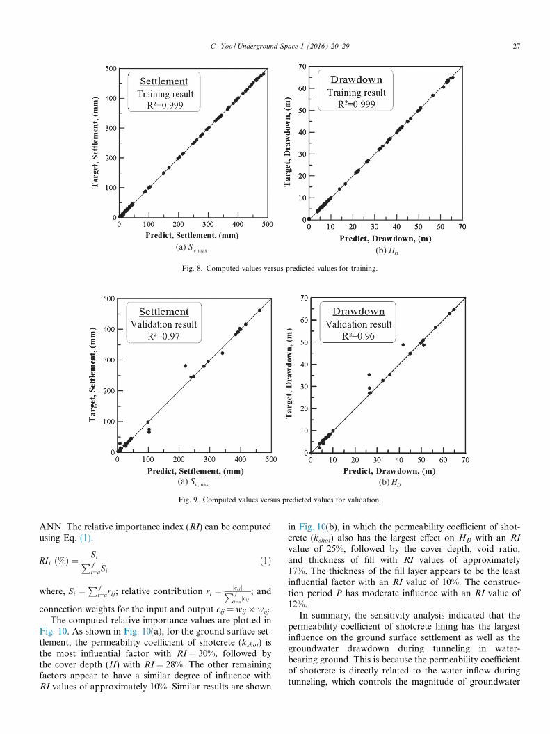
Figs. 8 and 9 show the performance of the ANN for thetraining and validation sets. As shown in these figures,excellent correlations between the ANN predictions andthe target values are observed in the output variables. Sta-tistically, excellent predictive capability is demonstrated asthe coefficient of determination R2 values exceed 99%. Thisdemonstrates the consistent predictive capability of theANN model for the validation sets and training sets.
3.2.3. Sensitivity analysis
To further investigate the relative importance of theinfluencing factors on the maximum ground surface settle-ment as well as the groundwater drawdown, a sensitivityanalysis was carried out using the developed ANN follow-ing the technique proposed by Garson (1991), which uti-lizes connection weights for the input and hidden layersðwij; i ¼ input;j ¼ outputÞ and for the hidden layers andoutput (woj; o ¼ output;j ¼ hidden layer) of the trained
Output
t (m/day) P (day) HD (m) Sv,max (mm)
02 317 26.50 98.86002 293 22.31 86.050002 1027 7.92 42.690002 283 6.75 38.9502 375 26.50 100.64
..
. ... ..
.
02 1027 7.80 14.0502 395 5.83 11.790002 283 3.75 7.78
..
. ... ..
.
0002 1027 6.95 44.940002 475 6.7 43.25
..
. ... ..
.
02 233 56.42 383.3202 537 62.80 451.3502 1027 63.52 438.96
..
. ... ..
.
002 376 5.15 27.08002 1027 8.37 38.54
..
. ... ..
.
0002 254 4.18 22.710002 558 6.60 31.43
(a) max,vS (b) DH
Fig. 8. Computed values versus predicted values for training.
(a) max,vS (b) DH
Fig. 9. Computed values versus predicted values for validation.
C. Yoo /Underground Space 1 (2016) 20–29 27
ANN. The relative importance index (RI) can be computedusing Eq. (1).
RIi ð%Þ ¼ SiP f
i¼aSi
ð1Þ
where, Si ¼P f
i¼arij; relative contribution ri ¼ jcijjP f
i¼ajcijj
; and
connection weights for the input and output cij = wij � woj.The computed relative importance values are plotted in
Fig. 10. As shown in Fig. 10(a), for the ground surface set-tlement, the permeability coefficient of shotcrete (kshot) isthe most influential factor with RI = 30%, followed bythe cover depth (H) with RI = 28%. The other remainingfactors appear to have a similar degree of influence withRI values of approximately 10%. Similar results are shown
in Fig. 10(b), in which the permeability coefficient of shot-crete (kshot) also has the largest effect on HD with an RIvalue of 25%, followed by the cover depth, void ratio,and thickness of fill with RI values of approximately17%. The thickness of the fill layer appears to be the leastinfluential factor with an RI value of 10%. The construc-tion period P has moderate influence with an RI value of12%.
In summary, the sensitivity analysis indicated that thepermeability coefficient of shotcrete lining has the largestinfluence on the ground surface settlement as well as thegroundwater drawdown during tunneling in water-bearing ground. This is because the permeability coefficientof shotcrete is directly related to the water inflow duringtunneling, which controls the magnitude of groundwater

0
10
20
30
40
Rel
ativ
e im
port
ance
, RI
(%)
Max. ground surface settlement, Sv,max
H GR ts kshot eo P
0
10
20
30
40
Rel
ativ
e im
port
ance
, RI
(%)
Max. groundwater drawdown, HD
H GR ts kshot eo P
(a) Ground surface settlement (b) Groundwater drawdown
Fig. 10. Results of sensitivity analysis using ANN.
28 C. Yoo /Underground Space 1 (2016) 20–29
drawdown and, therefore, the ground surface settlement. Itis concluded that minimization of the water inflow quantityinto the excavation area is of utmost importance in control-ling the ground surface settlement during tunneling inwater-bearing ground.
4. Conclusions
The results of a parametric study on the groundwaterdrawdown-induced surface settlement during tunneling inwater-bearing ground are presented. Numerous cases weredeveloped considering the Seoul metro extension designproject, in which ground settlements associated withtunneling-induced groundwater drawdown was an impor-tant design issue. A calibrated stress–pore pressure coupledfinite element model, which can simulate the tunneling andgroundwater interaction, was adopted for the parametricanalysis. The results were used to establish relationshipsbetween the ground surface settlement as well as ground-water drawdown and the influencing factors. An artificialneural network (ANN)-based sensitivity analysis was per-formed to obtain insight into the relative importance ofthe influencing factors. The following conclusions can bemade based on the findings from this study, however, theyare limited to design cases similar to those considered inthis study.
(1) The groundwater drawdown during tunneling causesan increase in the effective stress in the drawdownaffected area due to the pore pressure reductioncaused by the drawdown. The reduction in the voidratio causes additional settlement in addition to thesettlement that occurs by the unloading effect dueto tunnel excavation.
(2) The primary influencing factors on settlement devel-opment are the thickness and stiffness of the soil layerwithin the drawdown zone, and the shotcrete liningpermeability (amount of water inflow). The initialvoid ratio and the permeability of the soil layer withinthe drawdown zone are secondary influencing factors.
(3) The ANN-based sensitivity analysis indicates that thepermeability coefficient of shotcrete lining has the lar-gest relative importance value, which suggests thatthe permeability coefficient of shotcrete lining hasthe largest influence on the ground surface settlementas well as the groundwater drawdown during tunnel-ing in water-bearing ground.
(4) Measures that minimize the inflow quantity are ofutmost importance in limiting the ground surface set-tlement during tunneling in water-bearing ground.
Acknowledgements
This work was supported by Grant No. 2014004636 fromthe Basic Research Program of the Korea Science & Engi-neering Foundation as well as Grant No. 13CCTI-T01 fromthe Ministry of Land, Transport and Maritime Affairs,Korea. The financial support is gratefully acknowledged.
References
Abaqus users manual, VERSION 6.16, (2016). Pawtucket, Providence, R.I.: Hibbitt, Karlsson, and Sorensen, Inc.
Anagnostou, G. (2002). Urban tunnelling in water bearing ground –Common problems and soil mechanical analysis methods. In, 2nd Int.conf. on soil structure interaction in urban civil engrg., Zurich (pp. 233–240).
Attewell, P. B., Yeates, J., & Selby, A. R. (1986). Ground deformation andstrain equations. Soil movements induced by tunneling and their effects onpipeline and structures. Glasgow: Blackie (pp. 53–66).
Bernat, S., & Cambou, B. (1995). Modeling of tunnel excavation in softsoil. In, Proc. 5th symposium on numerical models in geomechanics (vol.1) (pp. 471–476).
Bowers, K. H., Hiller, D. M., & New, B. M. (1996). Ground movementover three years at the Heathrow Express Trial Tunnel. In Mair &Taylor (Eds.), Geotechnical aspects of underground construction in softground (pp. 647–652).
Davis, E. H. (1968). Theories of plasticity and the failure of soil masses. InSoil mechanics: Selected topics (pp. 341–380). London, U.K.: Butter-worth’s.
Garson, G. D. (1991). Interpreting neural-network connection weights. AIExpert, 6(7), 47–51.
Hornik, K., Stinchcombe, M., &White, H. (1989). Multilayer feedforwardnetworks are universal approximator. Neural Networks, 2, 359–366.
Mair, R. J., Potts, D. M., & Hight, D. W. (1991). Finite element analyses ofsettlements around a tunnel in soft ground, Contractor report.Crowthorne, Berkshire: Transport and Road Research Laboratory.

C. Yoo /Underground Space 1 (2016) 20–29 29
Norwegian Soil and Rock Engineering Association (NSREA). (1995).Norwegian urban tunnelling. Publication no. 10.
O’Reilly, M. P., Mair, R. J., & Alderman, G. H. (1991). Long-termsettlements over Tunnels. An eleven-year study at Grimsby. InTunnelling’91 (pp. 55–64). London: Inst. of Mining and Metallurgy.
Qiao, S., & Liu, B. (2006). Prediction of ground displacement anddeformation induced by dewatering of groundwater. UndergroundConstruction and Ground Movement, 73–79.
Queiroz, P. I. B., Roure, R. N., & Negro, A. (2006). Bayesian updating oftunnel performance for Ko estimate of Santiago gravel. In Proceedingsof the international symposium on geotechnical aspects of undergroundconstruction in soft ground, London, 15–17 June (pp. 211–217). Leiden,The Netherlands: Taylor and Francis/Balkema.
Rumelhart, D. E., Honton, G. E., & Williams, R. J. (1986). Learninginternal representation by error propagation. In D. E. Rumelhart, & J.L. McClelland (Eds.). Parallel distributed processing (Vol. 1). Cam-bridge, Mass.: MIT Press.
Shahin, M. A., Maier, H. R., & Jaksa, M. B. (2002). Predicting settlementof shallow foundations using neural networks. Journal of Geotechnicaland Geoenvironmental Engineering, ASCE, 128(9), 285–793.
Shen, S.-L., Tang, C. P., Bai, Y., & Xu, Y. S. (2006). Analysis ofsettlement due to withdrawal of groundwater around an unexcavatedfoundation pit. Underground Construction and Ground Movement,377–384.
Shen, S. L., & Xu, Y. S. (2011). Numerical evaluation of land subsidenceinduced by groundwater pumping in Shanghai. Canadian GeotechnicalJournal, 48(9), 1378–1392.
Shen, S. L., Ma, L., Xu, Y. S., & Yin, Z. Y. (2013). Interpretation ofincreased deformation rate in aquifer IV due to groundwater pumpingin Shanghai. Canadian Geotechnical Journal, 50(11), 1129–1142. http://dx.doi.org/10.1139/cgj-2013-0042.
Shen, S. L., Wu, H. N., Cui, Y. J., & Yin, Z. Y. (2014). Long-termsettlement behavior of the metro tunnel in Shanghai. Tunneling andUnderground Space Technology, 40(1), 309–323.
Xu, Y. S., Shen, S.-L., & Bai, Y. (2006). State-of-art of land subsidenceprediction due to groundwater withdrawal in China. UndergroundConstruction and Ground Movement, 58–65.
Xu, Y. S., Yuan, Y., Shen, S. L., Yin, Z. Y., Wu, H. N., & Ma, L. (2015).Investigation into subsidence hazards due to groundwater pumpingfrom Aquifer II in Changzhou, China. Natural Hazards, 78(1),281–296.
Yoo, C. (2005). Interaction between tunnelling and groundwater-numer-ical investigation using three dimensional stress–pore pressure coupledanalysis. Journal of Geotechnical and Geoenvironmental Engineering,ASCE, 131(2), 240–250.
Yoo, C., & Kim, S. B. (2006). Stability analysis of an urban tunnelling indifficult ground condition. Tunnelling and Underground Space Tech-nology, 21(3–4), 351–352 [Elsevier].
Yoo, C., & Kim, J. M. (2007). Tunneling performance prediction using anintegrated GIS and neural network. Computers and Geotechnics, 34,19–30.
Yoo, C., Lee, Y. J., Kim, S. H., & Kim, H. T. (2012). Tunnelling-inducedground settlements in a groundwater drawdown environment – A casehistory. Tunnelling and Underground Space Technology, 29(5), 69–77.