Ground Segment Overview Basic and Introduction
31
Reference ID: - Rev: 1.0 Status: Released Updated: 2-Apr-2021 by: Tayodit P. 1 Ground Segment Overview Basic and Introduction Tayodit Plaidoung Product Manager & Ground System Engineer for THEOS-2 SmallSAT/MMGS
Transcript of Ground Segment Overview Basic and Introduction

Reference ID: -Rev: 1.0Status: ReleasedUpdated: 2-Apr-2021by: Tayodit P.
1
Ground Segment Overview Basic and Introduction
Tayodit PlaidoungProduct Manager & Ground System Engineer for THEOS-2 SmallSAT/MMGS

Basic Introduction
2

Objective
• The purpose of this session is to give an understanding of
• The overview of ground segment
– Key elements that comprise ground segment on the ground station i.e. the antenna system and RF equipment
– General ground system and the interfaces typically encountered for interaction with the antenna systems
– Ground segment components and functionality
– Interface to other system
3

AcronymCONOPS Concept of Operation
GAF Geolocation Ancillary File
MOC Mission Operation Centre
MPS Mission Planning System
SEET System End to End Test
SOC Spacecraft Operation Centre
SSTL Surrey Satellite Technology Ltd
TC Telecommand
TM Telemetry
TT&C Telemetry, Tracking and Command
4

Responsibility
• The ground segment team responsible for design, develops, installs and support ground segments for use with SSTL satellites.
Technical skill/Knowledge
• Space segment introduction• Satellite mission design• Ground system design• Satellite operation• Familiarisation on SSTL ground segment • Engineering process (SSTL or other standard)• Network engineering• IT platform equipment• Software development (C/C++, JAVA, JavaScript, python)• Software validation and verification• Software Installation and Implementation
5

Overview Value Chain
6

System High-levelSpace Segment
Ground Segment
SOC MOC Antenna Ground Station
Launch Segment
X-Band Image dataS-Band TT&C
7

Satellite Operation CenterData receiving & Image Ground
Segment
Telemetry Data
Telecommand
Image Shooting
Customer
Mission
Planning Application
Satellite
Command
Imagery Raw Data
Operation Cycle
Customer
Service
8

Example Mission Control
NASA Mission Control CenterJohnson Space CenterHouston, Texas, USA
ESA European Space Operations Centre
(ESOC) Darmstadt, Germany
GISTDASatellite Control Room
Siracha, Chonburi
9
[Credit]
https://en.wikipedia.org/wiki/Mission_control_center[Credit]
https://en.wikipedia.org/wiki/European_Space_Operations_Centre

2,500 Km
Coverage Area
Sriracha Station
10

Ground Segment Overview
11

Ground Segment Overview for SmallSAT• Main components;
– Ground Station
o Includes the ground antenna and front end RF equipment
o Includes software for configuration and control of the antenna and RF equipment
– Spacecraft Operations Centre (SOC)
o Includes software to command satellite, display telemetry
o Flight Dynamics System
– Mission Operations Centre (MOC)
o Mission Planning
o Image processing
o Image Catalogue
o Payload File Archiving
12

SmallSAT Ground Segment Architecture
RF EQPT
Modem(Cortex CRT)
RF EQPT
Demodulator (VHR) SDP
S-Band Connector Application
(SSTL Proprietary)
STA-Server(Saratoga)
S-Band System
X-Band System
SSTL component
SOC
MOC
S-Band - RX : 2200-2300 MHz- TX : 2025-2120 MHz
X-Band - RX : 8400 -8450 MHz
13
ARQ

ASP
(GsnControl)
THEOS- 2 Sm allSA T
Multi GroundstationManagement System
ADP
Mission
Interface
Mission
Broker
Satellite Planner
Scheduler
Terra
MPS Database
ASP
ASP Database
AOCS Data Storage
Image Data Storage
Geometric Processor Catalogue
AOCS Metadata XML file (23)
Contact schedules (8)
Track
(GsnControl)
GSN Exec
Ephemeris
SaratogaWin
(GsnData)
WinIdle
(GsnData)
Script
(GsnTLM)
WinIdle
(GsnTLM)Binary schedules
(OUT files) (17)
DispTLM
Async Version
(GsnTLM)
DispTLM
IP version
(GsnTLM)
Low Speed
Server
(GsnData)
Archive Interface
Archive
Archive Database
SaratogaWin
(STA Server)
S-Band Connector
IP Router
FTP
Dropbox
TGS (12), TMS (13)
File transfer
Acquisition schedules
XML (16)
Javelin
(FDS)GPS Logs (1)
TLE(2)
TLE(4)TLE (4)
Catalogue Interface
Spacecraft Schedule Data (18)
Availability Schedule (6)
Availability Schedule (7)
Contact schedules (9)
Antenna Contact Schedule (10)
Real-time Telemetry (11)
Real-time Telemetry (11)
TGS (12), TMS (13)
Acquisition schedules
XML (15)
TDS (19)
TDS (20)
Raw Image Data (21)
GAF Data (22)
TDA (24)
TDA (25)
GISTDAFDS
TLE(2)
GPS Logs (1)
GISTDAMission Planning
(OPTEMIS)
SPS Interface
(Sensor Planning Service)
Catalogue
Catalogue interface
System Block Diagram
Ref: SmallSAT SSTL Ground System Architecture -rev0.8 (draft)
SSTL-SOC
SSTL-MOC
GsnControl GsnData GsnTLM GsnArchive
Mission Planning Image Processing
S-Band
Antenna Ground Station
X-Band
MMGS
MMGS
14

Spacecraft Operations Centre (SOC)
• SOC is monitoring and controlling thespacecraft through a set of commercialcomputers that are used for spacecraftTT&C operations.
15

SOC Components• Tracking and Scheduling• Commanding
– Type of command • Low level commanding e.g. critical command to serial protocol • High Level commanding e.g. based on IP protocols
• Telemetry (TM)– Type of TM
• Low Level Telemetry e.g list of critical telemetry• High Level Telemetry e.g. Real time telemetry, Historical telemetry (record telemetry)
• Doppler• Spacecraft-Ground Transfer :
– Payload Files– OBC Files
• Time Synchronisation• Payload Scheduling
16

Mission Operation Centre
• The MOC is used to plan spacecraft imaging operations and process andaccess downloaded mission payload data.
• It consists of payload planning and image processing software applications.
17

Mission Planning Server• Imaging tasks are planned by
operators using the Mission Planning System (MPS)
• Generates spacecraft activity schedules
Mission Planning Server
ling
Mission Planner
GINs
Flight Dynamics System
(Ephemeris)
Mission Broker
Acquisition Schedules
Input Output
Mission Interface
Mission Planer
Imaging tasks
Availability Schedule
TLE
TDSText-based Downlink
Antenna Contact
Schedules
18

Image Processing Server• Raw image data from ViaSat SDP
to the product subsystem which Radiometric processed by Terra and archives
• Transfer AOCS Logs data (Geo-location Ancillary File-GAF) to ADP, in order to pass processed AOCS metadata XML to the geometric processor
Image Processing
Serverling
Image data
Antenna System
Terra
MMGS
(Geometric Processor)
Input Output
AOCS log data ADP
AOCS Data Storage
Raw
GAF
19

Antenna Components – Mechanical• Pedestal
• Dish
• Motors
• Cabling and management
– Antenna Control Unit• SCU
– RF• Low Noise Amplifiers (LNA)
• SSPA
• D/C, U/C
• Waveguide/Feed system
– Environmental Sensors• GPS and Anemometer
• Wind
• Temperature
• Humidity
M&C Computers
GPS Antenna & Anemometer
LAN Hub
Cortex
SCU
ADU Box
SSPA
Local Box
Siren
Oil Pump
Grease Pump
GPS
D/CUP/C
Dehydrator
Servo Control Unit
Reflector & Feed
20

S-band(WATER)
S-band(CGC)
X-band(ViaSat)
X-band(L3)
Antenna Location
21
Antenna

S-band (WATER) X-band (VIASAT) X-band (L3)
22

GISTDA Antenna Ground Station (Hexapod)
Reflector
Hexapod
Feed
- 6.1 m- Carbon fiber
- Prime Focus- RX : 2200-2300 MHz- TX : 2025-2120 MHz
- Program Track- EL : 0-180o
- AZ : 0-360o
23

GISTDA Antenna Ground Station (3 Axis)
24

Ground Station Design• RF
o Frequencies and bandwidth o The existing RF environment like, any in-band interferers?o Customer/State Agency engagement to resolve interference signals – some legal, some illegal
• Environmento The weather conditions like at the site?o High wind conditions? Rain? Dust? Sand? Significant temperature variations? Snow and Ice?
• Factors affecting antenna and ground station system selection– Geographical location that blocking line of sight– Modulation Schemes – FSK or BPSK uplink? QPSK or 8PSK X-Band downlink?– Performance – link budget coordination with RF Team– Multi Ground station Support?– CONOPS o Direct downlink broadcast mode? ARQ on uplink to handle dropped packets?o Support for other satellites?
25

Ground Station Design (cont.)• Infrastructure
– Site infrastructure e.g. building design, electrical, air condition and construction
– Inter-building links as required (e.g. RF and IP LAN)
– IT Services – Internet access requirement, Email, FTP services
– Generate the facilities requirement documentation to cover electrical, air conditioning, civil engineering, Antenna mounting and load management, network, Internet, facilities etc.
• Networking Constraints
– Bandwidth estimation e.g, Gigabit infrastructure
– Inter-building links?
– Ground segment LAN as isolated or connected to customer LAN? Security constraints?
– Provision of remote access?
26

Antenna Ground Station – DIGINEOCompatibility Test
MMGS Commissioning
SSTL scope
Installation and Integration Test Commissioning
Ready for SmallSAT
GSSTL FAT
Subsystem Test
MMGS scope
System Ready for Installation and Integration
A
MMGSSubsystemAcceptance
Test
GISTDAFacility
ReadinessReview
SSTL Hardware Inspection
SSTLPost Installation Test
SSTL OSAT
SSTL IOTR
Commissioning
SmallSATEnd-to-End Test
Network Test
Legend
DIGINEOOSAT
DIGINEOFAT
GINs Interface Test
MIXERs Interface Test
GIPS Interface Test
Mobile X-Band Interface Test(Incl. MIPS)
Common Interface Test
B
F
DIGINEO Ready for MMGS
integration
ReadyFor MainSAT
Antenna Ground Station – SmallSAT GS
Compatibility Test
DIGINEO Integration
SSTL GS Integration
MMGS-SSTL GSIntegration test
C
SSTL Ground SegmentReady for MMGS Integration
Ground System Ready for Commissioning
H
AIRBUSIOTR
Commissioning
AIRBUS scope
GISTDAscope
LRR
LRR
MMGS - DIGINEO Integration Test
D
E
DIGINEO-MMGS Integrated
Ready for LRR
SSTL GS-MMGS Integrated
Ready for LRR
SmallSAT Ground Segment Test Strategy
• SSTL FAT
• MMGS Subsystem Acceptance Test
• GISTDA Facility Readiness Review
Stage A: Subsystem
level test
Stage C: System Installation
• SSTL Ground Segment Installation and OSAT
• Including – Antenna Ground
Station Compatibility Test
– Network Test
Stage E: Integration
• Verify Interface between SSTL-MMGS
• Should be done before SEET
Stage G: LRR
Commissioning
• Should be done before SEET
• SmallSAT LRR
27
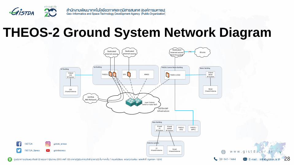
THEOS-2 Ground System Network Diagram
28
Water BuildingAIT Building
THEOS1 Control Room BuildingSat Building
Antenna systems
CGCS-band Antenna
WaterS-band Antenna
L3X-band Antenna
ViasatX-band Antenna
THEOS 2 THEOS 1 (CGS)SSTL MMGS
DedicatedInternet access
GISTDA SKPInfrastructure
GISTDABKK Network
Main Building
X-band L3
RF System
X-band VIASAT
RF System
S-BandWater
RF System
S-BandCGC
RF System
Layer 3 deviceSwitch or router tbd!!
DedicatedInternet access
DedicatedInternet access(CAT Provider)
KirunaVPN
THEOS 1 (IGS)
THEOS 1 (MPC)

• Physical Link Verification
• Routing Connection
GISTDA Facility Map
4.1 Image Acquisition andProduction
1. Space Centrariu2. AITBuilding
(Clean Room)
7. CGC S-Band Antenna (3 Fl.)
8. L3 X-Band Antenna
3. THEOS-1 Control Building
5. WATER S-Band Antenna
6. ViaSat X-Band Antenna
4.2 Data Centre
GISTDA BKK
Network
2.1 CCTV room
1.1 NOC room
1.2 Ground Server room
LAN (Clean room): 10
LAN (Office): 35
2.1 Cleanroom
Add SFP+ Cisco 10 Gbps (4 modules)
1 1
1
1
1
1
2
1
1
LAN (Acq. room): 10
29
Inter-Network Test

Ground Segment Hardware Workflow
Workstation
Example of Ground Segment Rack
RF Rack
30
[Credit] https://en.wikipedia.org/wiki/Data_center#/media/File:Datacenter-telecom.jpg

Thank you
31