GROUND IMPACT MITIGATION CARGO TRAILER M101. … · emrl tr 1025 ground impact shock mitigation...
38
00* GROUND IMPACT SHOCK MITIGATION ~ih~ CARGO TRAILER M101. 3/4-TON DAVID G. WIEDERANDERS NWMR TRt 1035 JULY 1067 LAPR 2 IJ69 B. ENGINEER NO (ME A NICS RE-SEARCH LABORATORY Trl UINiVFlIITY OF TFX.%S .UNI'lN. TEXA-S C LEfAR I NGIH40US E IfT -f n*,1 - -. le, 27,i, A V~v"215
Transcript of GROUND IMPACT MITIGATION CARGO TRAILER M101. … · emrl tr 1025 ground impact shock mitigation...

00*
GROUND IMPACT SHOCK MITIGATION~ih~ CARGO TRAILER M101. 3/4-TON
DAVID G. WIEDERANDERS
NWMR TRt 1035 JULY 1067
LAPR 2 IJ69
B.
ENGINEER NO (ME A NICS RE-SEARCH LABORATORY
Trl UINiVFlIITY OF TFX.%S .UNI'lN. TEXA-S
C LEfAR I NGIH40US E
IfT -f n*,1 - -. le, 27,i,
A V~v"215
EMRL TR 1025
GROUND IMPACT SHOCK MITIGATIONCARGO TRAILER M101, 3/4-TON
by
David G. Wiederanders
U. S. ARMY NATICK LABORATORIESAIRDROP ENGINEERING LABORATORY
Project No. 1F121401D195
CONTRACT DA 19-129-AMC-582(N)
Tg ,-,/-/T
ENGINEERING MECHANICS RESEARCH LABORATORY
THE UNIVERSITY OF TEXAS
Austin, Texas
July 21, 1967
PREFACE
This report is the third in a series-dealing wit gh
velocity dropping of military vehicle!Ander Contract
DA-19-129-AMC-582(N) with the U. S. Army Natick Laboratories.
The first report in the series is entitled Ground Impact Shock
ditigation-M-151 Utility Vehicle (Jeep). The second report is
entitled Ground Impact Shock Mitigation Cargo Truck, 3/4-Ton
N37.
These vehicles, as well. as the M1OI trai'.er discussed in
this report were the subjects of previous studies conducted by
the Structural Mechanics Research Laboratory under Contract
DA-19-129-QM1383. In these earlier studies, the damage
susceptibilities of the- vehicles were investigated with the
Impact velocities limited to a maximum of 30 fps. This was
the impact velocity specified at that time for airdrop. The
design acceleration at that time had been set somewhat arbitrarily
at 16g. Cushioning systems which provided adequate protection
and a drive-on, drive-off capability for the specified drop
conditions were developed and described in the reports issued.
For the present investigatioki, the only limitation on the
impact velocity was the height of the drop facility. For the
trailer, this was a drop from a height of about 47 feet. This
produced an impact velocity of about 55 fps. No limitation was
placed on the design acceleration other than that the vehicle
should be adequately cushioned. The maximum design acceleration
used was 30g and this provided adequate cushioning for the vehicle.
li
J4
A drive-on, drive-off capability was not designed into the
cushioning system since this was primarily a feasibility study.""Recommendations are given for improvements in the design
of the vehicle to improve its perfor.mance characteristics in
airdrop.
-E.- A-._Ripperger, Director 1Engineering Mechanics Research Laborator --:
The University of TexasAustin, Texas
October 3. 1967
i i-i

TABLE OP CONTENTS
Page
PREFACE . iiLIST OF FIdURhS v
ABSTRACT. . . . . . . . . . . . . . .* * **vi
INTRODUCTION. . . . . . . . . . . . . . 1
PROA URE .*. . .... ...... . . .. . . . . .. .. v4
- Drop Program.. . . . . . .. 5
.Problems Encountered . . ......................... 7
-zLifting Rig.................................. ... 8
Platform ......................................... 8
Honeycomb .................................. 10
-Instrumentation ........ ................... . 10
SUMMARY OF DROP PARAMETERS AND DAMAGE OBSERVED ........ 12
M101-1; Height 10 ft.; Acceleration 20g. ...... ... 12
-M101-2; Height 20 ft.; Acceleration 30g .......... 12
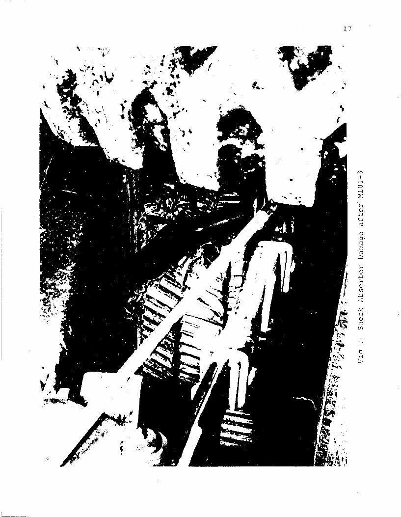
iM1O1-3; Height 30 ft.; Acceleration 30g ...... ... 15
Mlo1-4; Height 40 ft.; Acceleration 30g9 .... ....... 18
M101-5; Height 47.25 ft.; Acceleration 30g ... ..... 18
CONCLUSIONS ............. .................... ... 27
REFERENCES . ....................... 29
iv
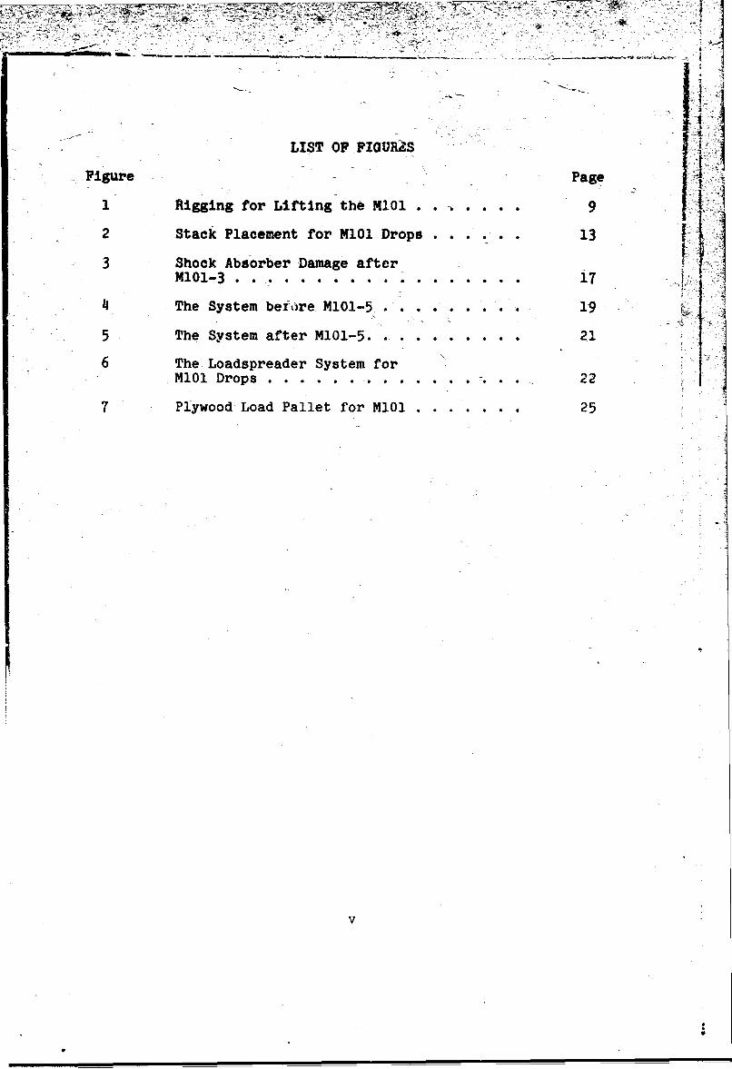
LIST OF FIOURŽS-
Figure Page
I Rigging for Lifting the MI01 . . .. . . . 9
2 Stack Placement for M101 Drops ...... 13
3 Shock Absorber Damage after -M101-3 ..................17
4 The System beiore M101-5 . . . ... . . . . 19
5 The System after M101-5. . . . . . . . . . 21
6 The Loadspreader System forM101 Drops . . . . . ...... ..... .... 22
7 Plywood Load Pallet for M101 ....... 25
v

OWN"
ABSTRACT
The present investigation and test series involving the Mi01
3/ 14-ton cargo trailer ht.s consisted of five di'ops of the vehicle
at impact velocities ranging from 25.4 fps, for the initial drop, 4
to 55 fps for the fifth and final drop of the series. During the.
series, the design impact acceleration was varied from 20-30g.The cushioning system used for each drop of the series is de-
scribed and the damage sustained by the vehicle during that drop
is discussed. It is concluded that this vehicle can be dropped
at impact velocities up to 50 fps without any damage, if a
properly designed cushioning system is employed to dissipate the
energy of the drop.
Recommendations for improvements, from the airdrop stand-
point, in the design of the vehicle are included.
vi

INTRODUCTION
During the past several-years, the nominal design impact
velocity for the airdrop of equipment and supplies hasýbeen 25
feet per second. This value has been maintained as the upper
limit of the impact velocity range which is encountered in an
actual airdrop situation. Impact velocities as low as 15 fps-
are frequently encountered under these conditions and must Itheref re be taken into consideration when designing the cushion-
system for a specific vehicle. This lower value of impact
velocity, however, presents no additional problem in the design
of an effective cushioning system, as the system will usually
perform effectively at impact velocities lower than those for
which it was designed. There are, however, other problems en-
countered when drops are made at low impact velocities. As
the impact velocity is reduced, the dispersion of the dropped
material is increased. This in turn decreases the accuracy of
the drop insofar as hitting the target is concerned. Also,
the additional time the equipment is in the air increases the
danger from possible enemy action. These problems coupled with
the study by Turnbow and SteyerI, which showed that the cost
of airdrop can be reduced appreciably by using a higher impact
velocity, employing relatively inexpensive paper honeycomb to
dissipate the energy of the drop, rather than the large expensive
parachute required to achieve the 15-25 fps impact velocities,
have prompted the investigation of the feasibility of dropping
SSuperscript numerals indicate references listed at the endof the report.
1t
2
vehicles at impact velocities higher than 25 fps.
In theory, at least, it is possible to cushion a vehicle so
that it will survive an impact of any velocity, but there are
other considerations. For example, the space available in air-
craft is limited. This obviously places a limit on the impact
velocity that can be sustained because the volume of cushioning
material increases as the square of the impact velocity. In
addition, the stability of the cushioning system becomes a
serious problem as the height of the cushioning stack increases.
In order to study some of the practical problems of
cushioning vehicles against high impact velocities; to discover
some of the hidden problems; and to determine the maximum
practical impact velocity for a specific vehicle; the program of
drops of the MI01 Cargo Trailer, which is reported here, was
undertaken.
The primary objectives of this investigation have been:
1. to verify that the vehicle could b: successfully
dropped at impact velocities as high as 50 fps,
2. to determine the design acceleration that would
be required for such a drop,
3. to work out the essential details of a prototype
cushioning system, and*
4. to observe the damage susceptibility of the vehicle.
The collection of data regarding the damage susceptibility
of certain specific vehicles is but one phase of the research
program which is intended to eventually put the design of
cushioning systems for the airdrop of equipment on a firm
engineering basis. However, a standard cushioning system appli-
cable to all vehicles is not feasible. Hence, each vehicle must
have its own system, and although these differ somewhat in
detail, they should all conform to the basic principles of
cushioning design as those principles are now understood.
PROCEDURE
In order to ascertain the effectiveness of the initial
cushioning design for this vehicle, it was decided to start
with a 20g impact acceleration and a drop height of 10 feet, and
to gradually increase to higher impact velocities and design
accelerations using the results of the test3 for guidance in
selecting the parameters for subsequent tests.
2A cushioning develo:,,ment test series had been conducted
for this vehicle se-reral years ago in which several systems were
tested for their effectiveness in protecting the vehicle from
damage. The results of these tests coupledwith the knowledge
which has been gained since that time were used to design the
initial cushioning system.
The vehicle used for this test series was an M101, 3/4-ton
Cargo Trailer supplied by the U. S. Army Tank-Automotive Center
under arrangements made through the U. S. Army Natick Laboratories.
in order to prevent undue damage to the trailer, the top
and sldera'ls -ere removed. Also removed were the stop light
and blackout markers. The vehicle was further adapted by in-
stalling lifting plates on each of the wheels, and a plywood
load pellet in the bed of the trailer. This loadspreader was
suggested by previous experience with the M37 truck. It was
supposed to prevent uncue bending in the floor of the trailer
due to the 1500 lb. dead load of sandbags used to simulate actual
loaded conditions of the vehicle throughout the test series.
4

5
As part of the drop program on the M37 truck3 tests were
made on the available honeycomb cushioning material to determine
the average crushing stress and energy-absorption characteristics.
The results of these tests were used to provide guidance
for the development of an effective cushioning system for the
MIO and M37.
Drop Program
The program followed in this test series called for the
first drop to be from a height of 10 feet with a design accel-
eration of 20g. In subsequent drops, both the height and design
acceleration were increased as seemed warranted by the results
of previous test. This was to allow an effective cushioning
system to be designed and tested at lower impact velocities
before relying on the-system at the higher impact velocities
and accelerations called for in later phases of this program. By
this plan, it was hoped that the limits of the vehicle could be
approached without critically damaging the vehicle. Hence, each
drop was designed to test changes made in the cushioning system
or to proceed to the next phase of the drop program.
In preparing for the initial drop of this series, the weight
distribution was calculated for the trailer, considering the
tongue and wheels as separate units. See Table 1. The weight of
the bed and simulated load was the main consideration in the actual
design of the cushioning system, as these areas constitute the main
weight factor of the trailer. This weight distribution coupled
TABLE 1Assumed Weight Distribution for the MI01
WEIGHT DISTRIBUTION (Empty)
Weight of Wheels 500 lbs.
Weight of Axle 100 lbs.
Bed and Frame-Forward of Axle 385 lbs.
Weight of Tongue Assembly 55 lbs.
Bed and Frame-To Rear of Axle 300 lbs.
Total Empty Weight 1340 lbs.
WEIGHT DISTRIBUTION (Loaded)
Weight of Wheels 500 lbs.
Weight of Axle 100 lbs.
Bed, Frame, and Load-Forwardof Axle 1230 lbs.
Weight of Tongue Assembly 55 lbs.
Bed, Frame, and Load-To Rearof Axle 955 lbs.
Total Loaded Weight 2840 lbs.
pal ....
7
A. 2with the results of the previous drop series was used in the
design of the cushioning system for the initial drop. Typical
design calculations may be found in the appendix of the final
report on the M37 Truck. 3
IProblems Encountered
Principal problems encountered were:
1. Weak frame bolts holding the bed to the frame.
2. Insufficient flat area under the bed of the trailer
to allow the trailer and load to be cushioned with-
out loadspreaders.
3. Weak flooring in the bed of the trailer allowing
considerable bending to occur at impact.
The last two of these problems were solved by the use of
three loadspreaders. Two of these were placed under the trailer
so that they transferred the force of the cushioning stack directly
to the floor of the trailer. The third loadspreader was placed
in the bed of the trailer to more everly distribute the force of
the simulated load. (Note: Dimensional sketches of these load-
spreaders are provided in a subsequent section of this report)
Because of their complexity, the fabrication of these loadspreaders
may not be practical from the field users standpoint. Consequently,
further study is needed to reduce the complexity of the loadspreader
system and to provide an effective system that is both simple and
economical for use at high impact velocities. However, since the
primary objective of this study was to determine the feasibility
8
of dropping at high impact velocities rather than the develop-
ment of an ultimate system suitable for field use, no attempt
was made to refine the design of the loadspreaders. With the
prototype system described in this report for guidance, the
development of a system for field use should not present any
significant difficulties.
Lifting Rig
The M101 trailer used for this test series was rigged for
drop by attaching lifting plates and shackles to each of the
wheels. To facilitate the lifting and leveling of the vehicle,
chains were attached to one end of each of three slings. One
of the chains was passed through each shackle and hooked back ion itself. The third sling was attached to the towing pintle
in the same manner. This allowed for quick adjustment of each
sling independently to achieve a level altitude of the vehicle
for the drop.
The two sling ropes attached to the wheels were separated
by a spacer beam to prevent damage to the vehicle and all three
were attached to a large lifting shackle. This shackle was en-
gaged by a helicopter hook which was released for the drop by
the Fastax-Camera timing control. The entire rigging is shown
in Fig. 1.
1
Platform
An 8 x 12-ft. plywood platform was designed and built,

Fig. I Riqqinq for Liftiniq the M101

10
fessentially to the specifications for the combat expendable plat-
form described in TM 10-500-13. This platform performed very
well and has been damaged only slightly by the five drops of
this series.
Honeycomb
The cushioning material used throughout this series was
80-0-1/2 paper honeycomb purchased directly from the manufacturer.
The average crushing stress determined for this honeycomb in a
test series involving stacks in excess of 12 in. in height was
2determined to be 6430 lb/ft2. This value was used in the cal-
culation for all drops of this test series.
Instrumentation
Accelerometers were mounted on the vehicle in the following
positions: Tongue, Center of Gravity, Rear Area. The front
accelerometer was mounted to large 1-1/2-in, thick steel plates
which had been bolted through the loadspreading pallet to the
bed of the trailer. It was found in previous drop series that
this procedure for mounting greatly reduced the vibration ampli-
tude indicated by the accelerometer.
In addition to acceleration records which were recorded on
both an oscillograph and magnetic tape, high-speed motion pictures
were made of all drops. These pictures were studied for an in-
dication of the efficiency of the cushioning system and for clues
as to what changes should be made to improve the performance of
I
the system. Both prior to and at the completion of each drop,
documentary photographs were taken. After a drop, the vehicle
was carefully examined for any visible damage and then it was
road-tested.

SUMMARY OF DROP PARAMETERSAND DAMAGE OBSERVED
M101-1; Height 10 ft.; Acceleration 20g.
For this initial drop, the weight distribution was calcu-
lated for the trailer considering the tongue and wheels as
separate units. The weight of the bed and the simulated load
was cushioned by two stacks placed under the ioadspreaders at
the quarter points of the loaded area. The wheels, axle, and
tongue were considered separate masses and cushioned independently.
The resulting cushioning reaction was balanced about the C.G.
of the system to eliminate any angular movement during rrushing.
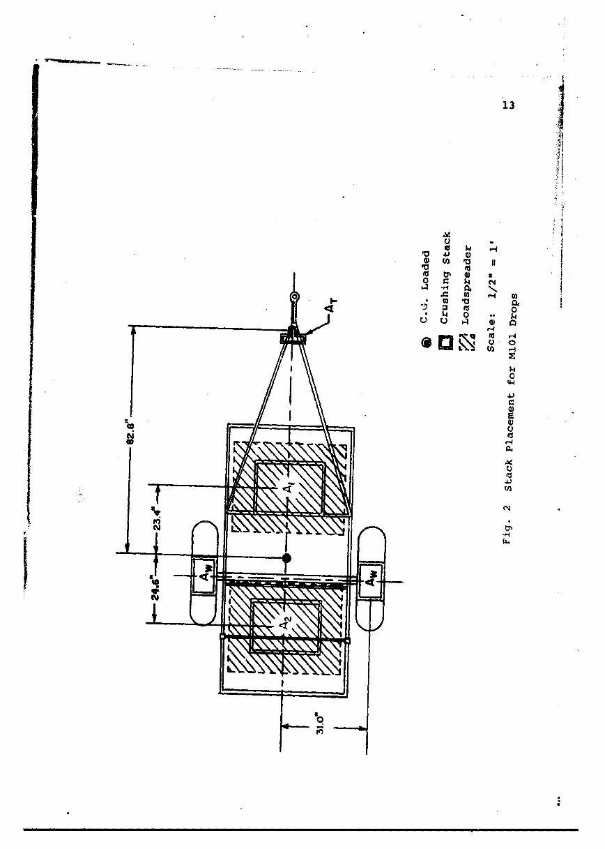
The position of the crushing stacks used for this drop, as
shown in Fig. 2, remained the same throughout the test series.
The areas shown in this figure provided for a design impact
acceleration of 20g.
The system performed well with both front and rear cushion-
ing stacks crushing to 65 percent.
There was no vehicle damage and no problems encountered.
Accelerations were taken with accelerometers placed on the
tongue, at the C.G., and at the rear of the load area. The
results are presented in Table 4. Black and white 16mm film
coverage was made from both the front and rear with full side
16mm Fastax coverage.
M!01-2; Height 20 ft.; Acceleration 30g.
This drop was made from a height of 20 ft. and at a design
m n i • m i m i m• m m i m i m i m ii i
137
tp 0
r-I
13 too
4.1
, 44
r ,
IV
0 Go i ._ _1. * '4 N
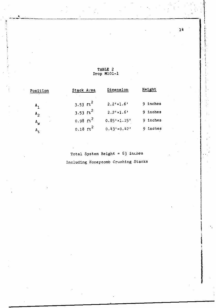
TABLE 2Drop M101-1
Position Stack Ailea Dimension Height
AI 3.53 ft 2 2.2'xi.6' 9 inches
2A2 3.53 ft 2.2'xl.6' 9 inches
22A 0.98 ft2 0.85'x1.15' 9 inches
W2
At 0.18 ft2 0.43'x0.421 9 inches
Total System Height = 63 inches
Including Honeycomb Crushing Stacks
I "
iI

15
impact acceleration of 30g in conformance with the tpst plan.
As mentioned previously, the same stack placement was used
for this drop as the M101-1. However, the area of each stack
was increased to provide the design acceleration of 30g. This
cushioning configuration was used for the remainder of the drops.
The'drop went as planned with the exception that during free
fall, there was a small angular rotation of the system.
The cushioning system performed satisfactorily, crushing
uniformly to 60 percent.
The only damage observed was the failure of one of the tie-
down bolts which holds the bed to the frame. This failure was
due to the nature of the tie-down design and the weakness of the
type of bolt used for this function. The manner in which the
head of the bolt is formed creates a severe stress concentration
at the cross section immediately below the head. This causes
the heads of the bolts to pop off.
M101-3; Height 30 ft.; Acceleration 30g.
This drop was designed to further study the effects of
high-impact velocities on the damage susceptibility of the
vehicle and to more closely determine a maximum design accel-
eration for this particular vehicle.
During the free-fall period of this drop, the system ro-
tated so that the rear of the platform was 18 in. lower than the
front at impact. Severe pitching of the load and uneven crushing
of the system resulted.
16
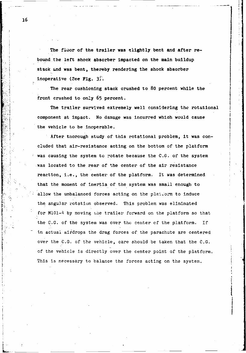
- The fioor of the trailer was slightly bent and after re-
bound the left shock absorber impacted on the main buildup
stack and was bent, thereby rendering the shock absorber
inoperative (See Fig. 31.
The rear cushioning stack crushed to 80 percent while the
front crushed to only 65 percent.
The trailer survived extremely well considering the rotational
component at impact. No damage was incurred which would cause
-the vehicle to be inoperable.
After thorough study of this rotational problem, it was con-
cluded that air-resistance acting on the bottom of the platform
was causing the system to rotate because the C.G. of the system
-was located to the rear of the center of the air resistance
* reaction, i.e., the center of the platform. It was determined
that the moment of inertia of the system was small enough to
allow the unbalanced forces acting on the plat.f.orm to induce
the angular rotation observed. This problem was eliminated
for MlO 1 14 by moving Lne trailer forward on the platform so that
the C.G. of the system was over the center of the platform. If
in actual airdrops the drag forces of the parachute are centered
over the C.G. of the vehicle, care should be taken that the C.G.
of the vehicle is directly over the center point of the platform.
This is necessary to balance the forces acting on the system.
[I
EIL- - - - - - - ______________________
17
4.j
rj-)
1-4
C)
4116-
18
M01-4; Height 40 ft.; Acceleration 30g.
This drop was made in accordance with the test plan. There
was no angular movement detected and no major problems encountered.
The system crushed to 65 percent with all stacks crushing
uniformly.
A bed tie down bolt was again broken; this problem, however,
is due to the weakness of the type of bolt used for this purpose
and could probably be prevented by using a bolt or fastener with
a better design.
The cushioning system used for this drop is considered to
be an effective design for use at high impact velocities and
was further tested by MlO1-5. The present system provides for
a design impact acceleration of 30g. This value is considered
as an optimum value since it provides for sufficient area to prevent Jstability problems in the cushioning stacks without subjecting
the vehicle to extremely high accelerations upon impact.
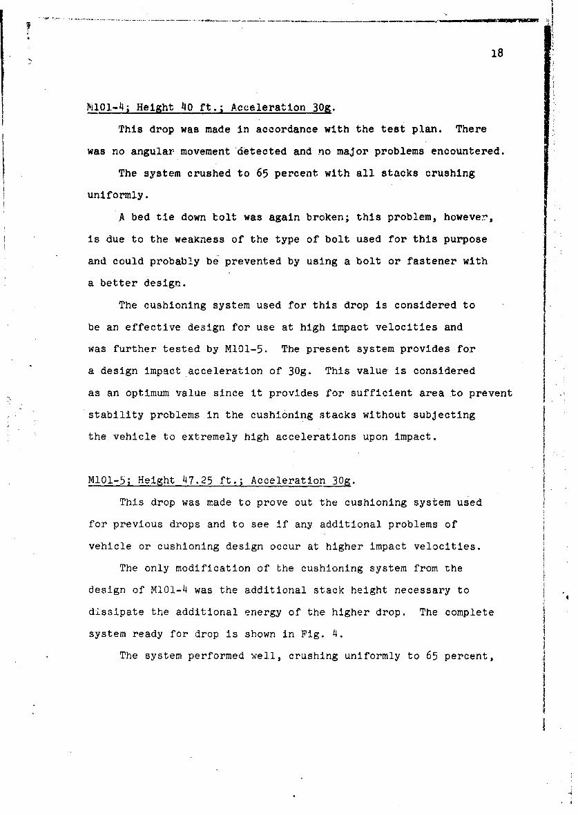
M101-5; Height 47.25 ft.; Acceleration 30g.
This drop was made to prove out the cushioning system used
for previous drops and to see if any additional problems of
vehicle or cushioning design occur at higher impact velocities.
The only modification of the cushioning system from the
design of M1Ol-4 was the additional stack height necessary to
dissipate the additional energy of the higher drop. The complete
system ready for drop is shown in Fig. 4.
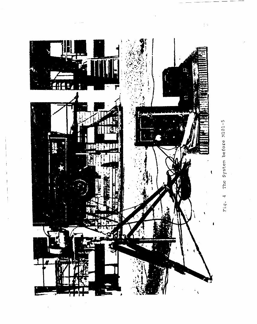
The system performed well, crushing uniformly to 65 percent,
'44
4-)tn
Vi~
tp)

20
with no damage to the vehicle being observed. Figure 5 shows the
system after this final drop of the series.
Although the cushioning system used for this drop performed
very well, it cannot be considered the ultimate design for the
vehicle. As relatdU previously, the effectiveness of the system
depends heavily on the use of a system of loadspreaders. Although
the design of these loadspreaders is not overly complex, it is not
considered feasible to use this type of spreader in an actual
air drop situation. However, since this test series was a
feasibility study rather than the development of an ultimate
system suitable for field use, no attempt was made to refine the
design of the loadspreader system. With the prototype system
shown in Fig. 6 as a guideline, the development of a system for
field use should not present any significant difficulties.
The trailer was examined thoroughly after this drop to be
certain that no damage was overlooked. It was determined that
the only permanent damage was the slight bending of the floor
of the bed encountered during M101-3.
The problem with the bed tie-down bolts is attributed, as
indicated previously, to a fauliy design which causes large stress
concentrations to develop where the shank joins the head of the
bolt.
It became evident during a previous test series involving
the dropping of vehicles with simulated loads, that considerable
deformation of the bed occurred unless the loading forces could
be carried into the frame through some means other than the
ILn
CD
II
22
4J M
$4 -
Er 0 d
* WV $4
I-I 0
4.4
4 1
>1
$4
0 4
P4
C*r.
23
TABLE 3Drop M101-5
Position Stack Area Dimension
A1 5.26 ft 2 2.2'x2.6' 24 inchesA 2
A2 5.26 ft 2 2.2kx2.6f 24 inches
t2Aw 1.45 ft 0.85,21.7, 24 inchesAt 0,30 ft 2 0.55,'O055, 24 inches
Total Area 14.90 ft 2
Total System Height = 75 " Including Honeycomb Cushioning Stacks
i.
2'4
relatively light metal floor in the bed. The loadspreader de-
signed and built for this purpose was effective in reducing the
bending of the bed. It is suggested that a similar loadspreader
be provided during actual drops if a load is to be dropped in
the vehicle (See Fig. 7). It probably would be better to
drop the vehicle empty and to place the load that normally
would be dropped in the trailer on the platform, protecting it,
of course, by the use of honeycomb.
Average accelerations and peak accelerations for all the
drops are shown in Table 4. In general, the measured average
acceleration is less than the design acceleration. This
phenomenon has been observed in previous studies and is
attributed to the flexibility of the vehicle structure which
actually provides some shock mitigation for itself. In Table 4,
Column 8, the integral of the acceleration record is shown.
The discrepancies between the impact velocity and the acceleration
integration are due mostly to the difficulty inherent in deter-
mining just where to stop the integration,
25
35. 5"
96"1
48"1
3,, 3,,
65"45145" ----- 0
Fig. 7 Plywood Load Pallet for 3/4-Ton Txailer MI01

26
v 0 0
ca fl% O1 0 -: t- 0 H It~t GJ-% ('v) 0 0 0 0n, o. r* N* ,,CO O
4--)
o) to to
<4L~ ~ 0
0 -l
0o 0.\ 0~ LCo\ '.0 0
o. - - H1) M 0ý) 0;(
0 0 0 H-J C\(Y \ _ Cu. -i 00 0 0 Hj --Z ý4I
C.)
0
z --- U- 4-
w 0 0-~ ~ ~ *
W CMj C1 L
;- )0 cj00 c d0 0 c 0 0 0F4 H H -IoX C)fAr40 i.r- 0 x r40 W t
m,--
CONCLUSIONS
1. The MI01 3/4-ton trailer can be dropped from a height
of 50 ft. to land with an impact velocity of 57 fps using
essentially the same techniques used for dropping at 25 fps.-
2. A cushioning-system designed for 30g average accel-
eration provides adequate protection for the vehicle. This
design acceleration could be used even at low-velocity drops
to reduce the required stack heights to a minimum.
3. Provisions should be made for palletizing the load
in the trailer bed, if the load consists of concentrated masses.'
4. Problem areas encountered could be at least partially .
resolved by redesigning certain parts of the vehicle as follows.
a. Change the bed tie-down bracket to eliminate the
moment arm between the bolt and the point of con-
tact of the clamp.
b. Change the specifications for the tie-down bolts
to provide for a stronger fastener.
c. Provide additional cross-bracing between the
structural members now used.
d. Specify a heavier gage flooring and design the
frame cross-bracing to provide a uniform
cushioning area.
5. It probably would be more convenient and more economical
to drop the trailer empty, and cushion the load separately on
the platform. Insufficient information is available at present,
however, for reaching a definite conclusion on this point.
27
0

28
6. It is evident from the results of this series of tests
that military vehicles can be safely dropped at impact velocities
in excess of 50 fps. At the present time, it would be desirable,
however, to drop a prototype vehicle of each type, under con-
trolled conditions to determine possible sources of weakness,
and to develop the a.ptails of the cushioning system for the
particular vehicle under consideration.
}:i !
2f
L•
REFERENCES
1. Turnbow, J. W. and C. C. Steyer, Cushioning for Air Drop,Part II, Air Drop Cost AnaZysis, Structural MechanicsResearch Laboratory, The University of Texas, Austin,1955.
2. Shield, Richard and Clarke Covington, Fragility Studies,Part IV, Cargo Trailer, MI(l, 3/4-Ton, Structural.Mechanics Research Laboratory, The University ofTexas, Austin, 1960.'
3. Wiederanders, D. G., W. L. Guyton-and E. A. Ripperger,Ground Impact Shock Mitigation, Cargo Truzk, 3/4-Ton M3?, Engineering Mechanics Research Laboratory,T•he University or Texas, Austin, 1966.
29
@"t
Uncla.;sificdSecuritr Classification
DOCUMENT CONTROL DATA- R&Df.eeiuedtv clfaeftha•;iow of (tlle. body -i ebabract and uindeairnd annotation mlwl be entered when the ov*wrst repor Is claxefie o
IOPAGINAfrNCG ACTIVI-Y (Corp.amo auwhw) 20. RCPONT SECURITY C LASSIVICA TION.:The University of Texas -6 GRU
Austin, Texas
I. -POR. T TITLE
GROUND IMPACT SIXCK MITIGATION CARGO TRAILER M101, 3/4-TON
OC-DSCRIPTIVE NOTL- jTypo at report ah1 incluxlve ddtoe)
Third in series of three dealing with high velocity drop.S• •- 5- AUTHOR(S) (L~tal name. first name. Initial)
Wiederanders, David G.
6. RE~p004T DATE 741 . i,,. -TOTAL NO. OFr PAGES~l 76. NO. Orr Rairl!
$,- CONTRACT oft GRANT NO. DA19-129-AMC-582(N) 9,. ORIGINATOR-S REPORTN NUM8(S)
SPR4OJECT rO 1F121401DI95 I 6-1A
9 b. OT.91%R REPORT NOMS) (A4ny othet numbers that may be awajiaed
th.'s report)
d:M. RL TR 1025
10. A V A IL ABILITYILIMITATION MOTICES
This document has been approved for public release anm sale; its distributionis unlimited.
I1. SUPPLEMENTARY NOTES SPONSORING MILITARY ACTIVITY
U. S. Army Natick LaboratoriesNatick, Massachusetts 01760
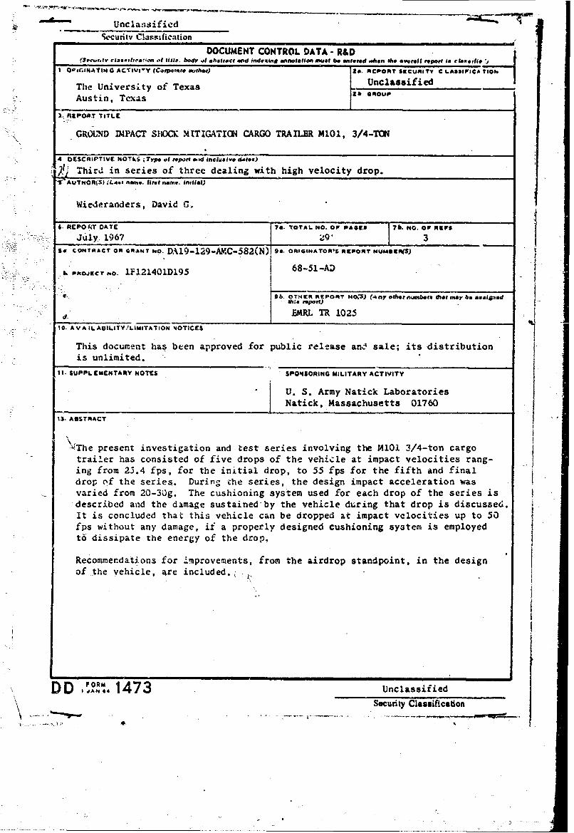
13. ABSTRACT
\4The present investigation and test series involving the M101 3/4-ton cargotrailer has consisted of five drops of the vehicle at impact velocities rang-ing from 23.4 fps, for the initial drop, to 55 fps for the fifth and finaldrop of the series. During the series, the design impact acceleration wasvaried from 20-30g. The cushioning system used for each drop of the series isdescribed and the damage sustained-by the vehicle during that drop is discussed.It is concluded that this vehicle can be dropped at impact velocities up to 50fps without any damage, if a properly designed cushioning system is employedt6 dissipate the energy of the drop,
Recommendations for improvements, from the airdrop standpoint, in the designof the vehicle, ;re included.
IANo 1473 Unclassified
"Security Classification

0 Pic as -- t.
14. LINK A LINK 0 LINK CKEY WO#4SO- - -f ROLE J VT ROLE WT ROLC WI'
Cushioning j8 6Cargo vehicles 9 7Trailers 9 7Armed Forces supplies 9 7Honeycomb construction 10Air-drop operations 4 4Impact shock 4 8 6
INSTRUJCTIONS
I.ORIGINATING ACTIVITY: Enter the name and addtess 1.AAADLYLMTTO NTIE:Enter any lim-,.t ihe contractor, subcontractor, grantee. Department of De- 1t0i.n onIAILTIIMT O fthrdseitoN OfThCES.prohrhntonfens,2 -ictivity or other organization (corporate author) issuing tiosnfuhedsemainofh rptterhntoe
~ imposed by security classufication, using standard statements
2a. ZŽEPORT SECURITY CLASSIFICATION: Enter the over- (1) "Qualified requesters may obtain copies of thisall security classific -tion of the report. Incticate whether
"I Res.ricted Data" is included. Mlarking is to be in accord- report from DDC2J ance with iappropriate security regulations. (2) "Floeign announcement and disseminst-on of this¶2h. GROUP;. Automatic downgrading is specified in DoD Di.reotbDCisntahoid.
rective 5-00. 10 and Armed Forces Industrial Manual. Enter (3) "U. S. Government agencies may obtain copies ofthe g.,oup number. Also, when applicable, show that optional this report directly from DDC. Other qualified DDC.mirkings :.dve beein used for Group 3 and Group 4 as author- users shall request throughixed.
3. REPORT TITLE: Enter the complete repor, title in all (4) 1"U. S. military agencies may obtain copies of thiscapta lte~a rs. itle in allcaesshould beuclassified. rehall directly from DDc. Other qualified users
tin hwttecasfctitninale _______________in__parenthesis_____
4. DESC'RIPTIVE NOTES: If appropriate, enter the type of (5) "All distribution of this report is controlled. Qual.report. e.g., interim, progress, summary, annual, or final. ified DDC users shall request through
Give the inclusive dates when a specific reporting period is Ifterpr a enfrihdt h fieo ehia5. AUTHOR(S): Enter the name(s) of author(s) as shown on Services. Department of Commerce, for sale to the public. indi-or in the report. Enter last name, first name, midt le initial. Cate this fact and enter the price, if known.I: If military, show rank and branch of service. Thc namie ofthe principal author is an absolute minimum requirement. 11. SUPPLEMENTARY NOTES: Use for additionial explana-
6. REPORT DATE, Enter the date of the report asday, tory noteiamonth, year. or month, year. If more than one date appears 12, SPONSORING MILITARY ACTIVITY: Enter fle name ofon the report, use date of publication, the depart.,tental project office or laboratory sponý ring (pay-7-a. TOTAL NUMBER OF PAGES: The total page count nfo)tersacaddvlpmt.Iluedrs.should follow normal pagination procedures. i.e., enter the 13. A1BSTRACT: Enter an abstract giving a brief and factualnumber of pages containing information. summary of the document indicative of the report, even though
it may also appear elsewhere in the body of the technical re-7b. NUMBlER OF RIr'ERENCES- Enter the total number of port. If additional space is required, a continuation sheetreferences cited in the report. shal be attached.
Sa. CONTRACT OR GRANT NUMBER: If appropriate, enter jIt is highly d*csirable that the abstract of classified r,?-
the applicable number of the contract or grant under which ports lie unclassified. Each paragraph of the abstract shallthe report was written, end with an indication of the military security classification
subroec ORGnATOer'S RytmnmePrT ,ts number, etc. There is no limitation on the length of !he abstract. How-9a, RIGNATO'S EPOT NUBER$):Ente th oft- eerthesuggested length is from 150 to 225 words.
cialreprt umbr b whch te dcumnt illbe dentfie 14 KE WODS:Key words are technically meaiiii~gful termsand ontolld b th orgintin acivit. Tis umbr mst r sortphrseRthot choracterize a repnrt and may be used as
be unique to this report. index entrien for cataloging the report. Key wordis most beQb. OTHtER RE-PORT NUMBER(S): If the report has been selacterl so that no security classification is rotitired. Iden.Iassigneil any other r-port numbers (eithe~r by the originator fivrm, such as equipment model designation, trade name, -i0i-Ior by ths sponsor)l, also enter this number(s). tory project code. name, geographic location, may bf isi' se as
key words but will be followed byv an indication of technicalcontext. The assignment of links, rules, find weights is
optional.
UnclaSsified_Se~curity Classi ication
.01