Groove Tubes LLC 1543 Truman Street, San … Tubes LLC...the American Tube Company, since 1979. 1543...
52
Groove TubesLLC...the American Tube Company, since 1979. 1543 Truman Street, San Fernando, CA91340, 818-361-4500 fax 818-365-9884 www.groovetubes.com "This box brings out the best from all my mics. When I want a tube pre I go to my Vipre, I wish I had a stereo version. I bought one for myself after trying it on several sessions, it's variable impedance allows me to match the mic with the performer and the slow rise time feature can really sweeten up a shrill vocal. I highly recommend this tube pre- amp." - Al Schmitt Jan, 2003 PRESS RELEASE The 12 time Grammy winning engineer/producer (with more on the way for this years Grammy nomination for Natalie Cole’s latest), Mr. Al Schmitt, talks about his ViPRE, and he is all smiles! Many thanks for the kind words Al.
-
Upload
nguyennhan -
Category
Documents
-
view
216 -
download
3
Transcript of Groove Tubes LLC 1543 Truman Street, San … Tubes LLC...the American Tube Company, since 1979. 1543...

Groove TubesLLC...the American Tube Company, since 1979.1543 Truman Street, San Fernando, CA91340, 818-361-4500 fax 818-365-9884
www.groovetubes.com
"This box brings out the best from all my mics. When I want a tube preI go to my Vipre, I wish I had a stereo version. I bought one for myselfafter trying it on several sessions, it's variable impedance allows meto match the mic with the performer and the slow rise time featurecan really sweeten up a shrill vocal. I highly recommend this tube pre-amp."
- Al Schmitt Jan, 2003
PRESS RELEASEThe 12 time Grammy winning engineer/producer (with more on the way for thisyears Grammy nomination for Natalie Cole’s latest), Mr. Al Schmitt, talks about hisViPRE, and he is all smiles! Many thanks for the kind words Al.
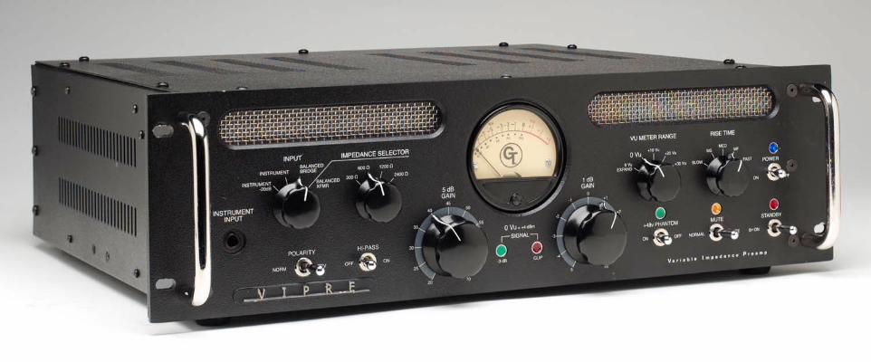
Groove TubesTM VipreTM
Variable Impedance Preamp
www.groovetubes.com
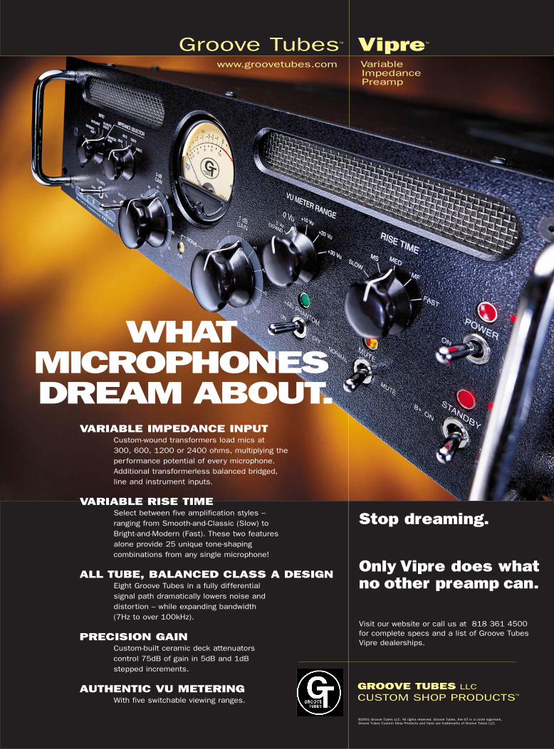
WHATMICROPHONESDREAM ABOUT.
GROOVE TUBES LLC
CUSTOM SHOP PRODUCTSTM
VARIABLE IMPEDANCE INPUTCustom-wound transformers load mics at 300, 600, 1200 or 2400 ohms, multiplying the performance potential of every microphone. Additional transformerless balanced bridged, line and instrument inputs.
VARIABLE RISE TIMESelect between five amplification styles – ranging from Smooth-and-Classic (Slow) to Bright-and-Modern (Fast). These two features alone provide 25 unique tone-shaping combinations from any single microphone!
ALL TUBE, BALANCED CLASS A DESIGNEight Groove Tubes in a fully differential signal path dramatically lowers noise and distortion – while expanding bandwidth (7Hz to over 100kHz).
PRECISION GAINCustom-built ceramic deck attenuators control 75dB of gain in 5dB and 1dB stepped increments.
AUTHENTIC VU METERINGWith five switchable viewing ranges.
Stop dreaming.
Only Vipre does whatno other preamp can.
Visit our website or call us at 818 361 4500 for complete specs and a list of Groove Tubes Vipre dealerships.
©2001 Groove Tubes LLC. All rights reserved. Groove Tubes, the GT in a circle logomark, Groove Tubes Custom Shop Products and Vipre are trademarks of Groove Tubes LLC.


Groove TubesTM VipreTM
Variable Impedance Preamp
www.groovetubes.com
WHATMICROPHONESDREAM ABOUT.
GROOVE TUBES LLC
CUSTOM SHOP PRODUCTSTM
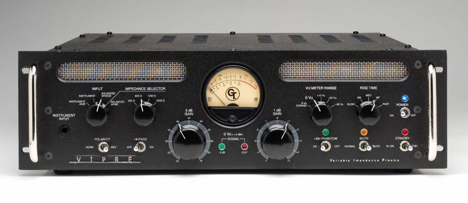
VARIABLE IMPEDANCE INPUTCustom-wound transformers load mics at 300, 600, 1200 or 2400 ohms, multiplying the performance potential of every microphone. Additional transformerless balanced bridged, line and instrument inputs.
VARIABLE RISE TIMESelect between five amplification styles ranging from Smooth-and-Classic (Slow) to Bright-and-Modern (Fast). These first two exclusive Vipre features alone provide 25unique tone-shaping combinations from any single mic!
ALL TUBE, BALANCED CLASS A Eight Groove Tubes in a fully differential signal path dramatically lowers noise and distortion – while expanding bandwidth (flat from 7Hz to over 100kHz!).
PRECISION GAIN CONTROLNo pots! Custom-built ceramic deck attenuators control Vipre’s incredible 75dB of total gain in 5dB and 1dB stepped increments for precision gain while maintaining the integrity of Vipre’s fully balanced signal path.
AUTHENTIC VU METERINGCustom-built, back lighted VU meter with five switchable viewing ranges.
Stop dreaming,Wake up your mics.
Only Vipre does whatno other preamp can.
Visit our website or call us at 818 361 4500 for complete specs and a list of Groove Tubes Vipre dealerships.
©2001 Groove Tubes LLC. All rights reserved. Groove Tubes, the GT in a circle logomark, Groove Tubes Custom Shop Products and Vipre are trademarks of Groove Tubes LLC.
VOG: Vipre Owners Group
“I heard the Vipre demo atthe NY AES show in New Yorkand I bought one rightaway...and gotten greatresults I would not have beenable to obtain otherwise.This is not just another firstclass mic pre - this box canhelp you get sounds out ofyour mic's that have eludedyou up until now.”Walter Becker, Steely Dan
“I've used it on voice, guitar,and bass, all with stunningresults!” Frank Filipetti, James Taylor, Carly Simon, EltonJohn, Barbara Streisand,Pavarotti, Celine Dion, others
“After extensive listeningtests comparing it to all othermic preamps at my studio,the Vipre came out way ontop in terms of sound clarityand depth.”Michael WagenerDokken, Ozzy OsbourneJanet Jackson, StryperAlice Cooper, many others
“This Vipre is just too good tosend back! I gotta have it!Here’s the check.” George PetersenMIX Editor, “Mr. Mix”


The Groove Tubes
Vipre
“I highly recommend this unit to anyone with vintage
mics. The Vipre made all the differencewhen it was compared to others made available to me
for the review. I can't say enough about this unit, and I
encourage all to check it out.”Mark Cross May 2001
Audio Media
“The Vipre mic preamp with it's variable impedance and
variable slew rate, gives me more tonal control than just
about any other preamp I've worked with. I've used it on
voice, guitar, and bass, all with stunning results.”Frank Filipetti, NYC
PRODUCER/ENGINEERJames Taylor, Carly Simon, Elton John, Barbara Streisand,Pavarotti, Celine Dion, Kenny G, Michael Crawford, and oh somany others...
“I heard the Vipre demo at the NY AES show in New York and I bought one right
away. Since I've had it I've used it in many different applications and gotten great
results I would not have been able to obtain otherwise.
This is a beautiful piece of equipment - well designed, lovingly crafted, a state-of-the-art
expression of Aspen Pittman's thinking on vacuum tube microphone preamplification.
As such, it offers a number of unique options for shaping the output of a favorite mic
so as to optimize it for a given
application. This is not just another first class mic pre - this boxcan help you get sounds out of your mic's that have eludedyou up until now.”Walter Becker March 2002
Steely Dan
What others
aresaying about
the Vipre
“The Vipre offers the engineer a whole new world oftube sound choices in a single, well-made, great-
sounding unit. The culmination of over three years of work by
Aspen Pittman and Groove Tube's engineering staff, Vipre is the
epitome of vintage tube amplification perfected for these digital
times.” Barry Rudolph August 2001
Mix MagazinePRODUCER/ENGINEER, Pat Benatar
“This Vipre is just too good to send back!
I gotta have it! Here’s the check...”George Petersen, Mr. Mix
Mix Magazine EDITOR
“I was unaware of the difference variable impedance could make in a microphone preamplifier. Now, I am a
believer. And now that I have had the occasion to have variable impedance
in an all-tube audio path with the ability to adjust the circuit’s rise-time, I am in hog heaven.
The Groove Tubes Vipre is a good as it gets.”Russ Long April 2001
Pro Audio Review
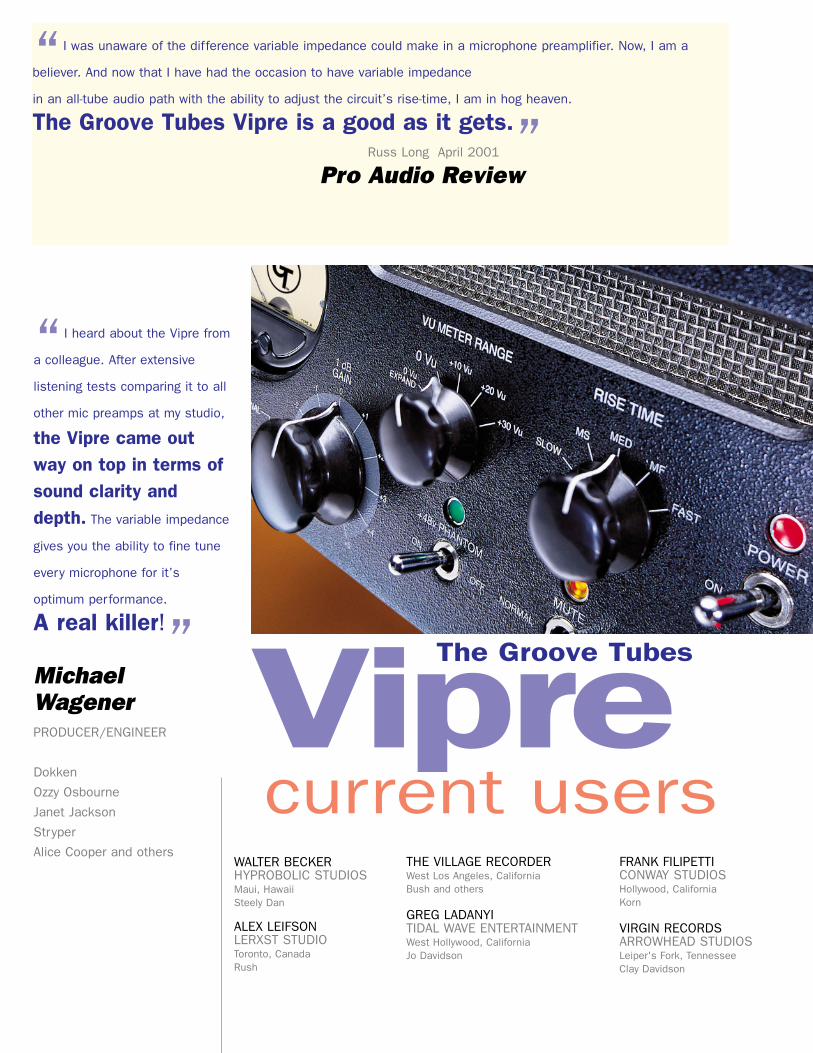
“I heard about the Vipre from
a colleague. After extensive
listening tests comparing it to all
other mic preamps at my studio,
the Vipre came outway on top in terms ofsound clarity anddepth. The variable impedance
gives you the ability to fine tune
every microphone for it’s
optimum performance.
A real killer!”MichaelWagenerPRODUCER/ENGINEER
Dokken
Ozzy Osbourne
Janet Jackson
Stryper
Alice Cooper and others
The Groove Tubes
Viprecurrent users
THE VILLAGE RECORDERWest Los Angeles, CaliforniaBush and others
GREG LADANYITIDAL WAVE ENTERTAINMENTWest Hollywood, CaliforniaJo Davidson
FRANK FILIPETTICONWAY STUDIOSHollywood, CaliforniaKorn
VIRGIN RECORDSARROWHEAD STUDIOSLeiper's Fork, TennesseeClay Davidson
WALTER BECKERHYPROBOLIC STUDIOSMaui, HawaiiSteely Dan
ALEX LEIFSONLERXST STUDIOToronto, CanadaRush
The Groove Tubes
Vipre
“The combination of the Groove Tubes Vipre mic pre with
an AM 40 was stellar! I used it the cellos for my new main title
for the CBS series ‘Survivor’ and they've never sounded so
good. Rich, pure – yet punchy – witha velvet sheen best describes thesound. Dialing-in varied impedance on the Vipre actually
change the sonic placement of the signal. I like it in my
face!”Russ LandauFilm score composer
On using a Vipre on the theme music
for the TV show ‘Survivor’
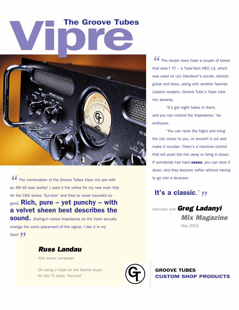
“The studio does have a couple of boxes
that aren’t TC – a Tube-Tech MEC LA, which
was used on (Jo) Davidson's vocals, electric
guitar and bass, along with another favorite
Ladanyi weapon, Groove Tube’s Vipre tube
mic preamp.
‘It’s got eight tubes in there,
and you can control the impedance,’ he
enthuses.
‘You can raise the highs and bring
the mic closer to you, or smooth it out and
make it rounder. There’s a rise-time control
that will push the mic away or bring it closer.
If somebody has hard esses, you can slow it
down, and they become softer without having
to go into a de-esser.
It's a classic.’”Interview with Greg Ladanyi
Mix MagazineMay 2001
GROOVE TUBES CUSTOM SHOP PRODUCTS

ARLY IN THE ANNALS OF PRO AUDIO,mics and mic preamps were often made by the same company, and the output
and input impedance between the mic andpreamp were matched to provide the bestpossible audio quality.
Those days are long gone now, and mostcondenser mics send a 200-250 ohm load intoan input about 10 times the impedance –roughly 2000-3000 ohms.
Altering the load against which the mic hasto push fundamentally alters the tone andcharacter of the output signal.
At the core of the Groove Tubes Vipre is amulti-tap high-performance input transformer,with four distinct positions: 300, 600, 1200 and 2400 ohms. This changes the workingimpedance or loading of a given microphoneand can strongly influence the sound qualitiesby the cumulative effects of small differences.
These differences vary from microphone tomicrophone, but all mics respond quite audiblywhen the preamp input impedance is altered.This control feature opens a much larger sonicwindow to each mic, and provides the ability tomagnify certain attractive tonal shifts in the wayit responds to impedance changes.
Vintage microphones are especiallysensitive to load terminations, as impedancematching was the norm in early broadcast andrecording facilities.
Ribbon mics, for example, are sought afterfor their smooth tonal properties. Whenproperly terminated or loaded with 300 ohms,the tonal characteristics change, and the soundseems to “bloom” in a way most people havenever heard.
The equalization changes slightly as well,with the entire spectrum from about 100Hz to15kHz taking on a very slight tilt, typicallyaround -1dB at the low end, and around +1dBat the upper registers. Very slight when lookingat individual frequencies, but the cumulativeeffect over the whole spectrum is unmistakable.
This kind of variation would be almostimpossible to recreate with any kind of EQ,unless the principle of a simple, unclutteredsignal path is abandoned altogether.
Moreover, a balanced-bridged ortransformerless input is provided, bypassingthe variable-impedance input transformeraltogether for a completely different soniccharacter.
An instrument input is also provided on thefront panel of the Vipre for easy access, andcan be padded by -20dB to accommodate thestronger output signals from active instrumentelectronics.
VARIABLE IMPEDANCE INPUTSAltering the input impedance changes the load against which the mic has to push. This dramatically alters the performance of any mic – from classic ribbons to vintage and modern condensers – even dynamics. All mics will respond similarly in that the apparentproximity gets ‘closer’ when the impedance islowered, but since you’re changing the load onthe mic, you’re altering the performance of themic – not the preamp.
Some vintage mic preamps (like Nevemodules) can be internally hard-wired to one of two different impedances. Avalon’s 2022and Joe Meek’s VC-1 both have an“impedance matching circuit” – consisting of a resistor network placed AFTER the load isalready terminated. But, this isn’t the same as what the Groove Tubes Vipre offers.
This is the only preamp we know of with a front-panel-selectable, truly variableimpedance transformer.
In short: You haven’t heard your mics untilyou’ve heard them loaded at differentimpedances. With all the control functionsavailable on this unit, anyone with even amodest selection of mics can dramaticallyincrease their tonal options by using a Vipre.
VARIABLE RISE TIMESRise-time is very much the same as “slew-rate” – the rate of speed at which theamplification circuit can amplify the signal.
You can't go from zero to five volts in notime – and how fast a circuit can amplify is partof what imparts its sound. Vintage circuits were much slower than are today’s, and – intheory – faster is better.
Faster amplification circuits retain theleading edge of the transient signal, especiallyapparent on the higher frequencies. Butslowing the rise time down can mellow orsmooth out the signal, often rounding-outharsh sibilants from vocals or edgy tones ofinstruments.
In a way, you can think of rise-times as a“time machine” for preamps – the slower therate, the more vintage the sound. No otherpreamp but the Vipre has this special feature.
GROOVE TUBES [email protected]
1-800-459-5687
ALL-TUBE, FULLY-DIFFERENTIAL CLASS A DESIGNClass A means that the same amplificationdevice (in this case, tubes) are doing the entirewaveform, both the maxima and minima of thewave.
Class AB and Class B use separate ampdevices to do the maxima (or top side) andminima (low side) of the wave. Those are moreefficient, but not nearly as accurate or true.
Fully-differential means that the signalremains balanced throughout, never becomingunbalanced or single-ended.
Almost all amp circuits break the balance.(In a console, the signal is single ended fromthe time it comes into the preamp, until bridgedat the output.) Vipre’s balanced signal path isaccomplished by using identical, mirror-imagesignal paths throughout, Therefore twice thecomponents are required at every stage – andwhy we use expensive ceramic deckattenuators instead of potentiometers for gainadjustments. This approach literally doubles the componentand labor cost, but distortion is lowered, andcommon mode-rejection ratios are significantlyimproved, as are signal-to-noise ratios.
PRECISION GAIN AND GENUINE VUIn order to maintain a fully floated and balancedsignal path throughout the entire circuit, thereare no potentiometers on the front panel.Instead, gain controls consist of ceramic deckrotary switch assemblies arranged for discretestep attenuation, providing repeatability, ultra-wide control range and superior accuracy.
To watch over all this signal manipulationcapability, the Vipre is fitted with a genuine VUmeter for signal observation – complete withfive separate types of VU response through anamplified VU meter driver circuit that allows foran “expanded view” of -20dB to +4dB – up toa -60dB to +9dB response.
BOTTOM LINE: ONLY VIPRE DOES WHATNO OTHER PREAMP CANHear the Vipre – along with our full line of micsand other signal processors at your Groove
“OHM-MAZING”DISCOVERIESSECRETS OF THE GROOVE TUBES VIPRE PREAMP
E
WHITE PAPER SERIES
The Groove Tubes Vipre is a mono-block, fully-differential Class A all-tube preampwith variable input impedance and adjustable rise time. It can be set for over 20different tonal variations – all without ever requiring EQ or other signal-degradingdevices to achieve them.

ContentsWelcome!..........................................................2
How to Use This Manual ...........................2
Important Safety Instructions........................ 3
Instructions de Sécurité Importantes (French)......4Beim Benutzen dieses Produktes beachten Siebitte die folgenden Sicherheitshinweise: (German).........................................................................6CE Declaration of Conformity..............................7
Quick Start Guide........................................... 8
Step 1: Hook it up ..............................................8Step 2: Set the Controls .....................................8
Phantom ..................................................8Input ........................................................8VU Meter Range.......................................8Mute Switch..............................................8Gain (Coarse 5 dB and Fine 1 dB) .............8Rise Time...............................................10Impedance Selector ................................10Hi-Pass..................................................10Polarity...................................................10
About the Instrument Input ...............................11Step 3: Experiment ..........................................11
Connections .................................................. 12
Unpacking and Inspection ................................12Installing in a Rack...........................................12Power .............................................................13
Avoiding ground loop noise .....................14Basic Connections ...........................................15
Output To a Mixing Console ....................15Connecting Microphones..................................18Connecting Instruments ...................................18Connecting Line Inputs.....................................18
About the Vipre............................................. 19
Why is the microphone preamplifier so important?.......................................................................19The Input Section.............................................20
About the Input Transformer....................20
Frequently-Asked Questions ................... 21About Vacuum Tubes ...................................... 22
Theory................................................... 22Impedance of tubes ................................ 22About Class A circuitry............................ 22Care and feeding of vacuum tubes .......... 23Tube Replacements................................ 23
The VU Meter.................................................. 24Clip LEDs............................................... 24VU Meter Range Control......................... 24
Gain Controls.................................................. 25GAIN Setting Procedures........................ 25
Overload characteristic .................................... 26Rise Time ....................................................... 27The Output Transformer................................... 27Mute Switch .................................................... 28Standby .......................................................... 28Block Diagram................................................. 29
Microphone & Preamp Theory....................31
About Impedance ............................................ 31The importance of impedance ................. 31
About Noise .................................................... 32Thermal Noise........................................ 32Microphone Self-Noise............................ 32Acoustic Noise ....................................... 32
Troubleshooting.............................................33
Troubleshooting Index ..................................... 33Care and Maintenance..................................... 33
Cleaning ................................................ 33Refer All Servicing to Groove Tubes ........ 34Obtaining Repair Service ........................ 35
Specifications.................................................36
Dimensional drawing ....................................... 37
Index................................................................38
Groove Tubes Limited Warranty.................39

Introduction/Safety Instructions
2 Vipre Reference Manual
Welcome!Thank you for making Groove Tubes' Vipre™ part ofyour studio. This is a truly unique product, so to take fulladvantage of the Vipre’s functions and enjoy long andtrouble-free use, please read this user’s manualcarefully.
How to Use This ManualThis manual is divided into the following sectionsdescribing the various functions and applicationsfor the Vipre. While it's a good idea to readthrough the entire manual once carefully, thosehaving general knowledge about microphonepreamplifiers should use the table of contents tolook up specific functions.
Chapter 1: Quick Start. This will get youstarted using the Vipre right away. It's a shortguide to the essential elements of hooking it upand using it for the first time.
Chapter 2: Connection. This chapter givesdetailed instructions for connecting the Vipre toa variety of typical audio systems.
Chapter 3: About the Vipre. This section givesdetailed information on the unique technology ofthe Vipre and how to use it.
Chapter 4: Microphone and Preamp Theorycovers deep background information that willhelp you use your Vipre, and all microphones, totheir greatest capability.
Chapter 5: Troubleshooting. This chaptercontains troubleshooting tips and serviceinformation should problems occur.
Helpful tips and advice are highlighted ina shaded box like this.
J When something important appears in
the manual, an icon (like the one on theleft) will appear in the left margin. Thissymbol indicates that this information isvital when operating the Vipre.

3 Vipre Reference
Important SafetyInstructions
Safety symbols used in this product
This symbol alerts the user that there areimportant operating and maintenance instructions inthe literature accompanying this unit.
This symbol warns the user of uninsulatedvoltage within the unit that can cause dangerouselectric shocks.
This symbol warns the user that outputconnectors contain voltages that can causedangerous electrical shock.
Please follow these precautions whenusing this product:
1. Read these instructions.
2. Keep these instructions.
3. Heed all warnings.
4. Follow all instructions.
5. Do not use this apparatus near water.
6. Clean only with a damp cloth. Do not sprayany liquid cleaner onto the faceplate, as thismay damage the front panel controls orcause a dangerous condition.
7. Install in accordance with the manufacturer'sinstructions.
8. Do not install near any heat sources such asradiators, heat registers, stoves, or otherapparatus (including amplifiers) that produceheat.
9. Do not defeat the safety purpose ofthe polarized or grounding-type plug. Apolarized plug has two blades with one widerthan the other. A grounding-type plug hastwo blades and a third grounding prong. Thewide blade or the third prong are provided foryour safety. When the provided plug doesnot fit into your outlet, consult an electricianfor replacement of the obsolete outlet.
10. Protect the power cord from being walked onor pinched, particularly at plugs, conveniencereceptacles, and the point where they exitfrom the apparatus.
11. Use only attachments or accessoriesspecified by the manufacturer.
12. Use only with a cart, stand, bracket, or tabledesigned for use with professional audio or
music equipment. In anyinstallation, make sure that injury ordamage will not result from cablespulling on the apparatus and itsmounting. If a cart is used, use
caution when moving the cart/apparatuscombination to avoid injury from tip-over.
13. Unplug this apparatus during lightning stormsor when unused for long periods of time.

Introduction/Safety Instructions
4 Vipre Reference Manual
14. Refer all servicing to qualified servicepersonnel. Servicing is required when theapparatus has been damaged in any way,such as when the power-supply cord or plugis damaged, liquid has been spilled or objectshave fallen into the apparatus, the apparatushas been exposed to rain or moisture, doesnot operate normally, or has been dropped.
15. This unit produces heat when operatednormally. Operate in a well-ventilated areawith at least six inches of clearance fromperipheral equipment.
16. This product, in combination with an amplifierand headphones or speakers, may becapable of producing sound levels that could
cause permanent hearing loss. Do notoperate for a long period of time at a highvolume level or at a level that isuncomfortable. If you experience anyhearing loss or ringing in the ears, you shouldconsult an audiologist.
17. Do not expose the apparatus to dripping orsplashing. Do not place objects filled withliquids (flower vases, softdrink cans, coffeecups) on the apparatus.
18. WARNING: To reduce the risk of fire orelectric shock, do not expose this apparatusto rain or moisture.
Instructions de Sécurité Importantes (French)
Symboles utilisés dans ce produit
Ce symbole alèrte l’utilisateur qu’il existedes instructions de fonctionnement et de maintenancedans la documentation jointe avec ce produit.
Ce symbole avertit l’utilisateur de laprésence d’une tension non isolée à l’intérieur del’appareil pouvant engendrer des chocs électriques.
Ce symbole prévient l'utilisateur de laprésence de tensions sur les raccordements de sorties,représentant un risque d'électrocution.
Veuillez suivre ces précautions lors del’utilisation de l’appareil:
1. Lisez ces instructions.
2. Gardez ces instructions.
3. Tenez compte de tous les avertissements.
4. Suivez toutes les instructions.
5. N’utilisez pas cet allareil à proximité del’eau.
6. Ne nettoyez qu’avec un chiffon humide.Il est potentiellement dangereuxd'util iser des pulvérisateurs ounettoyants liquides sur cet appareil.
7. Installez selon les recommandations duconstructeur.
8. Ne pas installer à proximilé de sourcesde chaleur comme radiateurs, cuisinièreou autre appareils (don’t lesamplificateurs) produisant de la chaleur.
9. Ne pas enlever la prise de terre ducordon secteur. Une prise murale avecterre deux broches et une troisièrmereliée à la terre. Cette dernière estprésente pour votre sécurité. Si lecordon secteur ne rentre pas dans laprise de courant, demandez à unélectricien qualifié de remplacer la prise.
10. Evitez de marcher sur le cordon secteurou de le pincer, en particulier au niveaude la prise, et aux endroits où il sor del’appareil.

Introduction/Safety Instructions
Vipre Reference Manual 5
11. N’utilisez que des accessoires spécifiés par leconstructeur.
12. N’utilisez qu’avec un stand, ou table conçuspour l’utilisation d’audio professionnel ouinstruments de musique. Dans touteinstallation, veillez de ne rien endommager àcause de câbles qui tirent sur des appareils etleur support.
13. Débranchez l’appareil lors d’un orage oulorsqu’il n’est pas utilisé pendant longtemps.
14. Faites réparer par un personnel qualifié. Uneréparation est nécessaire lorsque l’appareil aété endommagé de quelque sorte que ce soit,par exemple losrque le cordon secteur ou laprise sont endommagés, si du liquide a couléou des objets se sont introduits dans l’appareil,si celui-ci a été exposé à la pluie ou àl’humidité, ne fonctionne pas normalement ouest tombé.
15. Puisque son fonctionement normalegénère de la chaleur, placez cetappareil au moins 15cm. deséquipments péripheriques et assurezque l’emplacement permet la circulationde l’air.
16. Ce produit, utilisé avec un amplificateuret un casque ou des enceintes, estcapable de produite des niveauxsonores pouvant engendrer une pertepermanente de l’ouïe. Ne l’utilisez paspendant longtemps à un niveau sonoreélevé ou à un niveau non confortable.Si vous remarquez une perte de l’ouïeou un bourdonnement dans les oreilles,consultez un spécialiste.

Introduction/Safety Instructions
6 Vipre Reference Manual
Beim Benutzen dieses Produktes beachten Sie bitte die folgendenSicherheitshinweise: (German)
1. Lesen Sie die Hinweise.
2. Halten Sie sich an die Anleitung.
3. Beachten Sie alle Warnungen.
4. Beachten Sie alle Hinweise.
5. Bringen Sie das Gerät nie mit Wasser inBerührung.
6. Verwenden Sie zur Reinigung nur ein weichesTuch. Verwenden Sie keine flüssigenReinigungsmittel. Dies kann gefährliche Folgenhaben.
7. Halten Sie sich beim Aufbau des Gerätes an dieAngaben des Herstellers.
8. Stellen Sie das Gerät nich in der Nähe vonHeizkörpern, Heizungsklappen oder anderenWärmequellen (einschließlich Verstärkern) auf.
9. Verlegen Sie das Netzkabel des Gerätesniemals so, daß man darüber stolpern kannoder daß es gequetscht wird.
10. Benutzen Sie nur das vom Herstellerempfohlene Zubehör.
11. Verwenden Sie ausschließlich Wagen, Ständer,oder Tische, die speziell für professionelleAudio- und Musikinstrumente geeignet sind.Achten Sie immer darauf, daß die jeweiligenGeräte sicher installiert sind, um Schäden undVerletzungen zu vermeiden. Wenn Sie einenRollwagen benutzen, achten Sie darauf, dasdieser nicht umkippt, um Verletzungenauszuschließen.
12. Ziehen Sie während eines Gewittersoder wenn Sie das Gerät über einenlängeren Zeitraum nicht benutzen denNetzstecher aus der Steckdose.
13. Die Wartung sollte nur durchqualifiziertes Fachpersonal erfolgen.Die Wartung wird notwendig, wenn dasGerät beschädigt wurde oder aber dasStromkabel oder der Stecker,Gegenstände oder Flüssigkeit in dasGerät gelangt sind, das Gerät demRegen oder Feuchtigkeit ausgesetzt warund deshalb nicht mehr normal arbeitetoder heruntergefallen ist.
14. Dieses Gerät produziert auch imnormalen Betrieb Wärme. Achten Siedeshalb auf ausreichende Lüftung mitmindestens 15 cm Abstand von anderenGeräten.
15. Dieses Produkt kann in Verbindung miteinem Verstärker und Kopfhörern oderLautsprechern Lauts tärkepegele r z e u g e n , d i e a n h a l t e n d eGehörschäden verursachen. BetreibenSie es nicht über längere Zeit mit hoherLautstärke oder einem Pegel, der Ihnenunangenehm is. Wenn Sie einNachlassen des Gehörs oder einKlingeln in den Ohren feststellen, solltenSie einen Ohrenarzt aufsuchen.

Introduction/Safety Instructions
Vipre Reference Manual 7
CE Declaration of Conformity
Manufacturer’s Name: Groove Tubes llcManufacturer’s Address: 1543 Truman Street
San Fernando, CA 91340USA
declares, that the product:
Product Name: VipreModel Type: Microphone preamplifier
conforms to the Standards for Safety and EMC for this product listed on the Internet site:
www.groovetubes.com
chapter 1
8 Vipre Reference
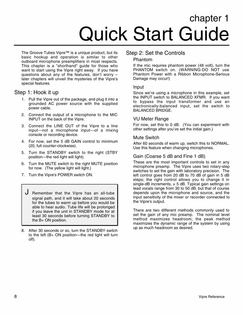
Quick Start GuideThe Groove Tubes Vipre™ is a unique product, but itsbasic hookup and operation is similar to otheroutboard microphone preamplifiers in most respects.This chapter is a "shorthand" guide for those whowant to start using the Vipre right away. If you havequestions about any of the features, don’t worry –later chapters will unveil the mysteries of the Vipre'sspecial features.
Step 1: Hook it up1. Pull the Vipre out of the package, and plug it into a
grounded AC power source with the suppliedpower cable.
2. Connect the output of a microphone to the MICINPUT on the back of the Vipre.
3. Connect the LINE OUT of the Vipre to a lineinput—not a microphone input—of a mixingconsole or recording device.
4. For now, set the 5 dB GAIN control to minimum(20, full counter-clockwise).
5. Turn the STANDBY switch to the right (STBYposition—the red light will light).
6. Turn the MUTE switch to the right MUTE positionfor now. (The yellow light will light.)
7. Turn the Vipre's POWER switch ON.
J Remember that the Vipre has an all-tubesignal path, and it will take about 20 secondsfor the tubes to warm up before you would beable to hear audio. Tube life will be prolongedif you leave the unit in STANDBY mode for atleast 30 seconds before turning STANDBY tothe B+ ON position.
8. After 30 seconds or so, turn the STANDBY switchto the left (B+ ON position—the red light will turnoff).
Step 2: Set the ControlsPhantomIf the mic requires phantom power (48 volt), turn thePHANTOM switch on. (WARNING-DO NOT usePhantom Power with a Ribbon Microphone-SeriousDamage may occur!)
InputSince we’re using a microphone in this example, setthe INPUT switch to BALANCED XFMR. If you wantto bypass the input transformer and use anelectronically-balanced input, set the switch toBALANCED BRIDGE.
VU Meter RangeFor now, set this to 0 dB. (You can experiment withother settings after you’ve set the initial gain.)
Mute SwitchAfter 60 seconds of warm up, switch this to NORMAL.Use this feature when changing microphones.
Gain (Coarse 5 dB and Fine 1 dB)These are the most important controls to set in anymicrophone preamp. The Vipre uses two rotary-stepswitches to set the gain with laboratory precision. Theleft control goes from 20 dB to 70 dB of gain in 5 dBsteps; the right control allows you to change it insingle-dB increments, ± 5 dB. Typical gain settings onlead vocals range from 30 to 50 dB, but that of coursedepends upon the microphone and source, and theinput sensitivity of the mixer or recorder connected tothe Vipre's output.
There are two different methods commonly used toset the gain of any mic preamp. The nominal levelmethod maximizes headroom; the peak methodmaximizes the dynamic range of the system by usingup as much headroom as desired.
chapter 1 • quick start guide
Vipre Reference Manual 9
To set the gain at nominal level:
1. Make sure the VU METER RANGE switch isset to "0".
2. With the source playing into the microphone,raise the 5 dB GAIN control until the VU meterof the Vipre is peaking at "0" or just barelygoing "into the red". Raise or lower the 1 dBGAIN control as necessary.
The average level of the output will be nominal(+4 dBu at the balanced line out, -10 dBV at theunbalanced line out) with peaks typically 8-10 dBabove that. The Vipre's green and red SIGNALlamps should never flash with this method.
NOTE: Preparing the Vipre rotary switchesfor silent operation.
Vipre uses special ceramic rotary switches tomaintain a fully balanced signal path. Lownoise resistors and high grade capacitors arehand soldered onto these rotary switch decks.These caps can become “charged” during thewarmup period and this can cause a loudpopping sound in some positions the firsttime they are activated. To eliminate this fromhappening we recommend:
1) Engage the mute switch to silence the Vipre .
2) Exercise all positions of the front panel rotaryswitches, switch them from full left to right .
3) Restore the Mute switch to Normal position.
4) This will insure silent operation. This step willneed to be repeated each time the Vipre isturned off for any period of time. Leaving theVipre in “Standby operation” (B+ off) will keepthe capacitors charged and so this step willnot need to be repeated when resumingoperation.
To set the gain using the peak method:
1. Set the Vipre's VU METER RANGE switch to"+10 Vu".
2. With the source playing into the microphone,raise the 5 dB GAIN control until the meter ofthe receiving unit (the mixer or recorder theVipre is feeding) is nearing its maximum level.
3. Carefully raise the 1 dB GAIN control until thereceiver's CLIP LED (or the Vipre's SIGNALCLIP LED, whichever lights first) flashesbriefly on peaks.
4. Back off either or both of the controls to dial inexactly the headroom you want (for example,one click back of the COARSE control andone click back of the FINE control would be 6dB below clipping).
5. If the Vipre's VU meter is pegging, change theVU METER RANGE to the +20 or +30position.
Unlike solid-state microphone preamplifiers,the Vipre exhibits a very gentle clippingcharacteristic...which is to say that it’s OK todrive it into clipping if that’s what the artisticsituation calls for. Note, however, that theVipre is capable of extremely high output,which may clip the following device; if therecorder or mixer has its own input levelcontrol, make sure it's set low enough to avoidclipping in that unit. In some situations, apassive attenuator may need to be insertedbetween the Vipre and the recorder/mixer; orthe –10 dBV BALANCED OUT may need tobe used instead of the LINE OUT.
quick start guide • chapter 1
10 Vipre Reference Manual
Rise TimeThere is no “right” setting for the RISE TIMEcontrol—just your artistic judgement. But generallyspeaking, settings toward the FAST side will soundmore “modern”, while settings towards SLOW willbring out the more “vintage” aspects of the preamp.See page 27 for more.
Impedance SelectorThis switch is only active when the INPUT switch is inthe BALANCED XFMR position. When it is, you canexperiment with any of the four impedance selections,from 300 to 2400 ohms (W). How this affects thesound of a mic will vary upon the microphone’s actualimpedance and other characteristics, but again,generally speaking, lower impedances are moresuited to older microphones.
The most “modern” or neutral setting of theVipre is to set the INPUT to Balanced Bridge(which bypasses the IMPEDANCESELECTOR entirely) and the RISE TIME toFAST. This is the setting that is most similarto contemporary solid-state console preamps,but with a more pleasing warmth. But the funreally starts when you start to experiment withthe fifty or so combinations that use thedifferent transformer impedances and differentrise times.
Hi-PassThis switch is another optional control; it rolls off thebass below 100 Hz at a gentle rate of 4 dB per octave.It’s designed to get rid of undesirable low-frequencyrumbles and noises. Note, however, that manymicrophones also feature high-pass filters of theirown; make sure the mic's filter is out if you want tohear the effect of the Vipre's Hi-Pass filter only.
PolarityThis reverses the “+” and “-“ of the input. Most of thetime, you’ll leave this set to NORM. It may not makean obvious difference, but ideally the polarity shouldbe set so that a positive pressure on the microphonegenerates a positive pressure from the speaker. Inother words, if you’re miking a drum, the first transientof a drum hit should make the loudspeaker moveforward , not back. Polarity also makes a difference inmulti-microphone situations, or when miking oppositesides of a diaphragm (above and below a pianosoundboard, a snare drum, etc.)
The Vipre is wired according the modernstandard of “Pin 2 = Hot”. Some oldermicrophones were wired with Pin 3 hot (i.e., apositive pressure on the diaphragm leads to apositive voltage on Pin 3); if you’re using oneof these, set the POLARITY switch to REV.

chapter 1 • quick start guide
Vipre Reference Manual 11
About the Instrument InputThe 1/4" input on the front panel labeledINSTRUMENT INPUT is specially designed for guitarand bass pickups. Instruments such as basses andguitars sound best if they “see” an extremely highinput impedance (1/2 megohm or greater). This inputfeeds a special high-impedance circuit with its owntube (a GT 6205), making the Vipre not only a greatmic preamp, but an incredible direct box for recordingbasses and guitars.
If the instrument has active electronics internally, itmay be so loud that it clips even at low settings of theGAIN controls, turn the INPUT switch toINSTRUMENT –20 dB.
As you may be able to tell from looking at the INPUTswitch, the front-panel INSTRUMENT INPUT jackdoes not use the input transformer, so theIMPEDANCE SELECTOR has no effect on it.However, RISE TIME and all the other controls doaffect the Instrument Input.
Alternatively, instruments may be plugged intothe LINE IN jack on the back panel for aslightly different sound. The impedance andthe first preamp tubes are different in thatinput.
Step 3: ExperimentOnce you have experienced the difference that theVipre makes on one microphone, you’ll want to tryevery other mic in your possession with it. You’ll findthat each mic reacts differently to the settings, and awhole new sonic palette will open up.
Finding the "right" settingThe Vipre's fundamental concept is different fromother kinds of studio equipment. Settings forimpedance and rise time will change the "flavor" of thesound, but will vary from case to case. The changesof each interact in very subtle ways…it's not nearly asobvious as changing the settings on an equalizer orcompressor/limiter. So, this manual doesn't provide achart that lists the "right" settings for a particularmicrophone, because the "right" setting can only bedetermined by your ears.
However, knowledge is power. There is considerableinformation about the Vipre in the following chaptersthat will help you understand the art and science ofwhy the Vipre affects your microphones the way itdoes. Read on.
chapter 2
12 Vipre Reference
ConnectionsUnpacking and Inspection
Your Groove Tubes Vipre was carefully packed at thefactory, and the shipping carton was designed toprotect the unit during shipping. Please retain thiscontainer in the unlikely event that you need to returnyour Vipre for servicing.
The shipping carton should contain the followingitems:
• Vipre Variable Impedance Preamp
• This instruction manual
• Power cable
• Groove Tubes Warranty card
• Rack mounting hardware (two pieces plus parts toattach them to the Vipre when rack mounting).
J It is important to register your purchase; if youhave not already filled out your warranty cardand mailed it back to Groove Tubes, pleasetake the time to do so now.
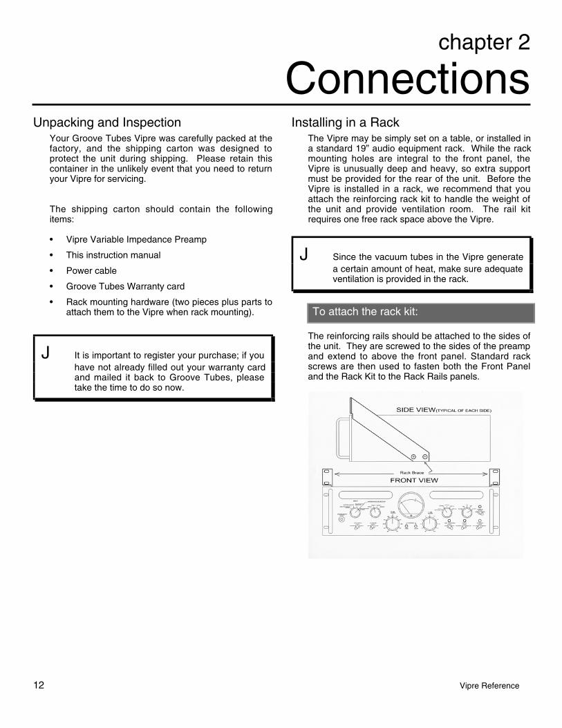
Installing in a RackThe Vipre may be simply set on a table, or installed ina standard 19” audio equipment rack. While the rackmounting holes are integral to the front panel, theVipre is unusually deep and heavy, so extra supportmust be provided for the rear of the unit. Before theVipre is installed in a rack, we recommend that youattach the reinforcing rack kit to handle the weight ofthe unit and provide ventilation room. The rail kitrequires one free rack space above the Vipre.
J Since the vacuum tubes in the Vipre generatea certain amount of heat, make sure adequateventilation is provided in the rack.
To attach the rack kit:
The reinforcing rails should be attached to the sides ofthe unit. They are screwed to the sides of the preampand extend to above the front panel. Standard rackscrews are then used to fasten both the Front Paneland the Rack Kit to the Rack Rails panels.

chapter 2 • connections
Vipre Reference Manual 13
Power
Make sure you read the initial Important SafetyInstructions chapter at the front of this manual.
The Vipre works with a single standard line voltageand comes with a detachable AC line cord suitable forthe destination to which the preamplifier is shipped.Units sold in the United States are designed for usewith 110 to 120 volt AC power (nominal 60 Hz), butthere is a plug-in voltage selector in the power entrymodule in the rear-panel switch allowing voltageconversion to 100V or 220V–240V operation.
The line cable is an IEC-spec AC power cabledesigned to be connected to a grounded 3-pin outlet,with the third, round pin connected to ground. Do notsubstitute any other type of AC cord; IEC-spec cablesof various lengths may be purchased from electronicsstores or your Groove Tubes dealer.
The ground connection is an important safety featuredesigned to keep the chassis of electronic devicessuch as the Vipre at ground potential. Unfortunately,the presence of a third pin does not always indicatethat an outlet is properly grounded. You may use anAC line tester to determine this. If the outlet is notgrounded, consult with a licensed electrician. WhenAC currents are suspected of being highly unstable inVAC and Hz, a professional power conditioner shouldbe used.
To connect power to the Vipre, attach the female endof the AC power cord to the Vipre’s back panel andthe male end to a good quality, noise-free AC powersource of the proper rating.
Do not operate any electrical equipment withungrounded outlets. Plugging the Vipre into anungrounded outlet, or “lifting” the unit offground with a three-to-two wire adapter, cancreate a hazardous condition. Groove Tubescannot be responsible for problems caused byusing the Vipre or any associated equipmentwith improper AC wiring.
Voltage conversion
If you need to use the Vipre in a country with adifferent voltage, contact Groove Tubes to locate aservice center in your area. Changing the voltagerequires internal adjustment on circuit boards thatoperate at dangerous voltage levels. Again, refer to aGroove Tubes service center for adjustment.
NEVER OPERATE THE VIPRE AT ADIFFERENT VOLTAGE THAN THATMARKED ON THE UNIT. This will damage theunit.
connections • chapter 2
14 Vipre Reference Manual
Avoiding ground loop noiseIn today’s studio, where it seems every piece ofequipment has its own computer chip inside, there aremany opportunities for ground loop problems to occur.These show up as hums, buzzes or sometimes radioreception and can occur if a piece of equipment “sees”two or more different paths to ground. While there aremethods to virtually eliminate ground loops and strayradio frequency interference, most of the professionalmethods are expensive and involve installing aseparate power source just for the sound system.Alternatively, here are some helpful hints thatprofessional studio installers use to keep those strayhums and buzzes to a minimum.
ÿ KEEP ALL ELECTRONICS OF THE SOUNDSYSTEM ON THE SAME AC ELECTRICALCIRCUIT.
Most stray hums and buzzes happen as a result ofdifferent parts of the sound system being pluggedinto outlets of different AC circuits. If any noisegenerating devices such as air conditioners,refrigerators, neon lights, etc., are alreadyplugged into one of these circuits, you then have aperfect condition for stray buzzes. Since mostelectronic devices of a sound system don’t requirea lot of current (except for power amplifiers), it’susually safe to run a multi-outlet box or two from aSINGLE wall outlet and plug in all of thecomponents of your system there.
ÿ KEEP AUDIO WIRING AS FAR AWAY FROM ACWIRING AS POSSIBLE.
Many hums come from audio cabling being toonear AC wiring. If a hum occurs, try moving theaudio wiring around to see if the hum ceases ordiminishes. If it’s not possible to separate theaudio and AC wiring in some instances, makesure that the audio wires don’t run parallel to anyAC wire (they should only cross at right angles, ifpossible).
ÿ TO ELIMINATE HUM IF THE ABOVE HASFAILED:
A) Disconnect the power from all outboarddevices and tape machines except for theVipre, the mixer and control room monitorpower amp.
B) Plug in each tape machine and outboardeffects device one at a time. If possible, flipthe polarity of the plug of each device (turn itaround in the socket) until the quietestposition is found.
C) Make sure that all of the audio cables are ingood working order. Cables with a detachedground wire will cause a very loud hum!!
D) Keep all cables as short as possible,especially in unbalanced circuits.
If the basic experiments don’t uncover the source ofthe problem, consult your dealer or technician trainedin proper studio grounding techniques. In some cases,a “star grounding” scheme must be used, with themixer at the center of the star providing the shieldground on telescoping shields, which do NOT connectto the chassis ground of other equipment in thesystem.

chapter 2 • connections
Vipre Reference Manual 15
Basic ConnectionsOutput To a Mixing ConsoleSince the Vipre is a high-output preamplifier, its LINEOUT (1/4” TRS Balanced +4dB) should be connected toa balanced line input of a console, not to themicrophone input whenever possible.
If the console's line input has an XLR input, you're inluck–simply connect a standard XLR-to-XLR cable fromthe Vipre's output to the line input of the console.
However, the line input of most modern consoles is athree-conductor TRS 1/4" phone jack, as shown below:
To maintain the benefit of fully-balanced operation, youwill need to get an XLR female to 1/4" male TRSadapter or cable, like this:
Pin 2 (+)
Pin 3 (-)
Pin 1 (Ground)
Sleeve (Ground) Tip (+)
Ring (-)
Important tip: Many XLR-to-1/4" adapters sold at electronics stores are NOT adapters, but transformers (and verylow quality transformers at that). Don't use these on the output of the Vipre—they're unnecessary andgenerally sound awful because they don't have the headroom to handle the Vipre's output. Get a hard-wiredadapter or cable from your professional audio dealer, or make one yourself from components.

connections • chapter 2
16 Vipre Reference Manual
If you must connect to a MIC IN jack:
Whenever possible, the output of the Vipre should beconnected to a balanced line input of a console,designed for a nominal input of +4 dBu (1.23 volts).However, in some situations you may have no otherchoice than to connect to the XLR MIC IN of a consoleor sound system. If this is the case, to avoid clippingof the console’s input:
• Set the console’s input gain (which may belabeled TRIM, ATT, GAIN, or MIC) to its lowestsetting.
Turn off any phantom power coming from theconsole if possible.
• If there is an input pad switch (labeled PAD, ATT,-20 DB, etc.), turn it on.
• With the Vipre’s gain set for optimum, asdescribed in the first chapter, see if the console’sinput is clipping. If it is, you can either turn downthe Vipre’s GAIN controls, or insert a lineattenuator between the Vipre and the console.
• Instead of using the Vipre's XLR LINE OUT jack,connect the Vipre's Lower Balanced 1/4" TRSoutput to the unit. This cuts the output level of theVipre by 11.8 dB (the difference between a +4dBu and –10 dBV nominal level).
Connecting directly to a +4 dBu recorder
Tip: For the cleanest possible recording, connectthe Vipre directly to the inputs of the recorderand avoid going through a mixing consoleentirely while tracking.
Professional recorders typically feature balanced3–pin XLR line-level balanced inputs. This allows youto connect the LINE OUT of the Vipre directly to theinput of the track you plan to record on. The nominalsignal level of these units is +4 dBu (1.23 volts).Balanced cables between the recorder and the Viprecan be very long, if necessary, without adding noise.
Digital Recorders. Many Digital multitrack Recordersfeature a multipin ELCO or EDAC connector thatfeatures 8 balanced inputs and 8 balanced outputs ona single connector. To connect the Recorder directlyto the Vipre, obtain an ELCO-to- TRS multipair cable.This will connect from the ELCO-type connector onthe Recorder on one end, fanning out to sixteenconnectors (labeled INPUT 1, OUTPUT 1 and so on)on the other end. Simply plug the 1/4" TRS Input onthe desired track of the Digital Recorder into theVipre's XLR output. Using a cable assembly with 1/4"TRS plugs allows a choice of the +4dBm levelreferenced output jack on the Vipre, or the -10 dBVoutput jack. Because the Vipre uses balancedtransformer outputs, an unbalanced plug may be usedwith either 1/4" output jack and will automaticallyconvert the jack from balanced to unbalancedoperation with no loss of signal level.
Note that some recorders with XLRs may not be trulybalanced, with pin 2 or 3 (depending on vintage) tiedto ground, which may cause a ground loop. Also,depending on the characteristics of the deck, meteringlevels may not match between the deck and the Vipre.Some multitracks have high/low level input switches;follow the manufacturer’s instructions on setting theseproperly.
chapter 2 • connections
Vipre Reference Manual 17
Connecting to an unbalanced device
Although it's not ideal, the Vipre may feed anunbalanced input of a console or recorder and stillprovide excellent results, particularly if the cablelengths are short and the AC power system is notcomplicated.
The -10dBV 1/4" jack output of the Vipre can be usedfor this purpose. If the receiving device has a 1/4"input jack, obtain an 1/4"-to-1/4" (mono) cable oradapter. The nominal output of this output is –10 dBV(.316 volts), at the same time that the balancedoutputs on the XLR and upper 1/4" connectors areputting out +4 dBu (1.23 volts).
If you want to use the 1/4" or XLR outputs:It is possible to use the +4 dBm balanced 1/4" or XLRoutput of the Vipre to feed an unbalanced device.Note, however, that besides being balanced, thesedevices put out a hotter level that may overload theinput of the receiving device.
Use an adapter similar to the one shown on page 15.The adapter may be an XLR-to-TRS or an XLR-to-1/4"mono jack; in either case, pin 3 (-) must be connectedto the shield, preferably at the input to the device.
Alternatively, if there are noise problems, you may tryisolating the device by building or purchasing aspecial cable that uses the balanced output on pins 2and 3 of the Vipre to feed the + and – connectors ofthe unbalanced receiver, leaving the ground floating(disconnected) at the receiver's end. (The shield muststill be connected at the Vipre to provide some path toground for interference.)

connections • chapter 2
18 Vipre Reference Manual
Connecting MicrophonesThe balanced female XLR connector on the rear panelis intended for use by low-impedance microphonesneeding preamplification. It is wired in the standardconfiguration (Pin 1 shield, Pin 2 “hot”, Pin 3 “cold”)and will receive 48-volt phantom power when the 48VPHANTOM switch is on. (WARNING-DO NOT USEP H A N T O M P O W E R W I T H R I B B O NMICROPHONES-SERIOUS DAMAGE MAY RESULT)
When the GAIN switches are both set to maximum,the signal at the XLR jack will be amplified 75 dB.When both GAINs are at minimum, it will be amplified15 dB.
Warning about connecting line-level sourcesto the XLR input:
Though the XLR IN may be used with a balanced line-level source such as the output of a VCR, headroomwill be limited; even with the GAIN at minimum, theinput will clip when the input level rises above +10dBu. For this reason, it’s better to connect balancedline sources to the 1/4" LINE IN jack on the rear panelusing an XLR-to-1/4” TRS adapter or cable.
Never connect an electronic line input to theXLR IN jack if phantom power will be turnedon. Doing this could damage the equipmentand the Vipre.
Connecting microphones with outboardpower supplies
Many high-quality microphones, such as the GrooveTubes microphone systems, feature outboard powersupply boxes that connect directly to the microphoneusing a multipin cable. The power supply usually hasa standard 3-pin XLR output, which should beconnected to the XLR input of the Vipre using ashielded microphone cable.
This type of microphone doesn't require phantompower from the Vipre, so leave the 48V PHANTOMswitch on the front panel OFF.
Connecting InstrumentsThe Vipre has a 1/4" jack on the front panel labeledINSTRUMENT INPUT. This is intended for inputs that"like" extremely high impedances, such as electricguitars and basses. Simply plug an unbalanced 1/4"cable into the jack, and set the INPUT switch toINSTRUMENT.
This jack has a nominal impedance of 470 kohms,more than twice that of a typical line input on aconsole. This keeps the pickups of the instrumentfrom being loaded down and improves high frequencyresponse.
For that reason, it is not necessary to use a "directbox", either passive or active, between a guitar andthe Vipre. The Vipre is, itself, an extremely high-quality direct box.
If the CLIP light goes on when the instrument isplayed even though the gains are turned down tominimum, set the INPUT switch to INSTRUMENT –20dB. You may need to increase the GAIN controls ofthe Vipre to compensate a little for this attenuation.
Connecting Line InputsOn the rear panel is a 1/4" jack labeled "BALANCEDLINE INPUT". This jack is in parallel with the XLRmicrophone input, but has a 20 dB lower sensitivity.When the front panel gain controls are at +30 (5 dBGain Switch)and +1(1 dB Gain Switch), a +4 dBminput to the LINE IN jack will be equivalent to unitygain (+4 dBm output). If you need to connect theoutput of a line-level device such as a signalprocessor, synthesizer, or recording device throughthe Vipre, connect it here.
The 1/4" BALANCED LINE IN jack does NOT connectto the input transformer, but directly to theBALANCED BRIDGE position of the INPUT switch.Set the INPUT SWITCH to that position to hear signalat the LINE IN jack. Disconnect any connection to theMIC IN jack when using the LINE IN jack.
chapter 3
19 Vipre Reference
About the VipreWhy is the microphone preamplifier so important?
In today's era of high-resolution digital recording, thesonic characteristics of the microphone preamplifierhave become crucial in determining the overall soundquality. Most of the gain in the recording signal pathis provided by the mic preamp, and accordingly thedynamic range of the recording is set by the noisefloor of the preamp. The wider availability of large-diaphragm condenser microphones, coupled with thescarcity of vintage equipment properly designed foruse with those microphones, has been another trendthat focused attention on the preamp. Many recordingstudios own large assortments of mics and preampsin order to be better prepared for the needs of variousartists and groups. And for good reason: the moretonal variations a facility can provide, the more diverseand desirable their clientele. The choice ofmicrophone and preamp are primarily responsible forthese variations.
The 20-bit and 24-bit digital recorders now commonlyavailable allow engineers to capture subtleties thatused to be lost in tape noise or covered up byirregular frequency response. Early complaints aboutthe "harshness of digital" have been recognized forwhat they are: complaints about inferior microphonepreamps that are only now being revealed by theaccuracy of digital recording. The engineers atGroove set out to build an authentic, no-compromisemic preamp that utilizes the best of vintage technologyto fulfill the potential of today's digital technology.
They have achieved that goal with the Vipre (VariableImpedance Preamp), an all-tube variable impedancemicrophone preamplifier with selectable rise time andVU meter range. It's a premium single-channel devicedesigned for critical recording applications demandingthe ultimate in mic preamplification. It featuresextremely wide frequency response, low inter-stagefeedback, very high gain, enormous dynamic range,and graceful overload characteristics.
Each component in the signal path was carefullychosen for its sonic purity. When components werenot available "off the shelf", they were custom-manufactured to Groove Tubes' exactingspecifications. Even the phenolic knobs on the frontpanel were custom-molded. But as you will read inthe rest of this chapter, the attention to detail goeswell beyond the appearance of the front panel. Mostimportantly, unlike other "tube preamps" that feature asingle vacuum tube in a largely transistorized circuit,
the Vipre has NO semiconductors, transistors,integrated circuit chips, or electrolytic capacitorsanywhere in the signal path.

about the Vipre • chapter 3
20 Vipre Reference Manual
The Input SectionAbout the Input TransformerThe Vipre features an exclusive input transformercustom-made in California to the highest industrystandards. A key feature is that it's a multitaptransformer, allowing a selection from four differentload impedances for a microphone. (Some other"variable impedance" products on the market simplyswitch in additional resistors, which actually makesthem "variable resistance"–—a subtle but potentiallyaudible difference because of the insertion losses thatresistors cause.)
Benefits of transformers, generallyWhile modern solid-state input circuitry can deliverexcellent results at very low cost, input transformersdeliver several significant advantages:
• Greater CMRR (common mode rejection ratio):this means that noise from the cable that appearson both the + and – leads simultaneously is morelikely to be rejected. Solid-state differentially-balanced circuits may have a good CMRR spec at1 kHz, but often aren't as good at otherfrequencies.
• More resistance to RF (radio frequencyinterference): the windings of a transformer,being naturally inductive, reject ultra-high radiofrequencies without requiring a capacitor in theaudio path as electronically-balanced circuits do.
• Lower impedance: it is easier to build a low-impedance input transformer than a low-impedance transistor input (which is one of thereasons the industry went to bridging impedancesin the last few decades).
• A transformer is fully floating, isolating the circuitfrom DC offsets, and to a certain extent fromsurges and stray signals. You could think of it asa magnetic link that keeps the circuits free frommutual contamination.
For these and other reasons, the highest-level audioconsoles, especially those used by touring soundcompanies, have always used input transformers. Butgood quality input transformers are expensive, andcheap input transformers used in affordable consolesseveral decades ago gave transformers a bad namewith some engineers due to their irregular frequencyresponse and distortion.
The input transformer used in the Vipre is a totallydifferent story. Special care is taken to shield thetransformer windings from noise: a high-qualitydouble Mu-metal can surrounds the transformer. Thetransformer itself is a "humbucking" type, withspecially-wound oppositional coils that cancel out
induced noise from the environment or nearbycircuitry.
Impedance: Matching vs. bridgingIn early audio devices, circuits were designed tomaximize power transfer between units. This meantthat input and output impedances should be matched,e.g. a 150-ohm source would be terminated by a 150-ohm load. This impedance matching maximized thecurrent in the load, at a time when every bit of currentwas necessary due to primitive amplification methods.One obvious down side to impedance matching wasthat a single source couldn't easily feed several inputsat once.
After the advent of high-impedance solid-statecircuitry, the era of maximum power transfer was overand the focus shifted to conveying signals throughvoltage, not current. The microphone or other sourcegenerates a varying voltage, but very little current isdrawn in the circuit because the load it "sees" is sohigh that it may as well be connected to nothing at all.Most modern audio equipment is designed to presenta very high impedance load to the source. The typicalinput impedance of a load is designed to be 10 to 20times the output impedance of a typical source. Thisis called a bridging input. (For a more in-depthexplanation of the importance of impedance, see page31.)
But what is the actual impedance of the microphoneyou're plugging in? And what kind of circuit was thatmicrophone designed to "see" for optimumperformance? Particularly in the case of vintagecondenser and ribbon microphones, the originaldesign usually were set up for impedance matching ,not bridging. When these microphones are pluggedinto the MIC IN jacks of today's solid-state micpreamps or consoles, they're seeing a very differentload than they were designed for. When they'replugged into the input of the Vipre and the impedanceis set to lower values, they exhibit the more opensound heard on classic recordings. Yet, othermicrophones may need to see a higher, bridging loadfor best performance. In any case, altering the loadagainst which the microphone has to pushfundamentally alters the tone and character of theoutput signal. The Vipre gives you the best of bothworlds. A key to this flexibility is the input transformer,which is the first component the microphone "sees"when the INPUT SELECT switch is in the XFMRpositions.
What’s the best input impedance?
There is no best one. Like EQ or effects, the “right”setting is the one that sounds best in a particularsituation. However, it might help you to choose a
chapter 3 • about the Vipre
Vipre Reference Manual 21
setting if you understand what’s going onelectronically. The choice of impedance between300W, 600W, 1200W and 2400W on the front panel willmake slight variations in equalization and residualdistortion, depending upon the individual mic.
For example, an early broadcast microphone like theRCA 77 will sound smoother when terminated at300W. The tonal characteristics change, and thesound seems to "bloom" in a way most people havenever heard. The equalization changes slightly aswell, with the entire spectrum from about 100 Hz to 15kHz taking on a very slight tilt, typically around –1 dBat the low end, and around +1 dB at the upperregisters. This is very slight when looking at individualfrequencies, but the cumulative effect over the wholespectrum is unmistakable. This kind of variationwould be almost impossible to recreate with any kindof equalizer, unless the principle of an simple,uncluttered signal path is abandoned altogether.
Tip: Try matching the era with the impedance:Generally speaking, the older the microphone,the lower the impedance. Microphones fromthe 1940s and '50s can handle 300W quitewell. Mics from the '60s tend to "like" 1200Wwhile those from the '70s and '80s prefer2400W. New mics, since they were designedin an era when almost all consoles have high-impedance bridging inputs, will sound the waythe designers intended when the Vipre'sINPUT is in BALANCED BRIDGE mode. But,this is just a starting point. The IMPEDANCESELECTOR switch is an "audio timemachine", and can make new mics sound likevintage mics. Remember: you can't hurt amicrophone by setting the input impedanceincorrectly.
Frequently-Asked QuestionsIf I set the impedance too low, will it hurt themicrophone?No. Even microphones with their own power suppliesare protected against a dead short.
Is there a special setting for ribbon microphones?Vintage ribbon mics like the RCA 77 were designed inan era when impedances were supposed to bematched to give maximum power transfer. Thesemics are particularly suited for the Vipre’s 300-ohmsetting. (Note: DO NOT USE PHANTOM POWERWITH RIBBON MICROPHONES. SERIOUSDAMAGE CAN RESULT)
But modern ribbon mics (like those from Beyer andRoyer) tend to be designed for higher impedances,although you can try them at any setting.
How come it sounds so different in bridged mode?Because it’s bypassing the transformer, with its manycomplex impedance and inductance characteristics,and using a purely electronic input with a much higherimpedance.
Aren’t electronic inputs cleaner than transformerinputs?Input transformers got a bum rap several decadesago, mostly because of the sound of the cheapversions used in popular consoles. But a high-quality,custom-wound transformer such as that used in theVipre doesn’t have that kind of degradation. Inaddition, the common-mode rejection of noise of atransformer, especially at high frequencies, is superiorto that of an electronic circuit.
Having said that, a transformer does have certainnonlinearities that may not be suited to certainapplications. That’s why the Vipre gives you a choice.The BALANCED BRIDGE position, the inputtransformer is bypassed, giving you a modernelectronically-balanced, 12 kW impedance input.

about the Vipre • chapter 3
22 Vipre Reference Manual
About Vacuum TubesTheoryTubes are the original devices for amplifying signals.Although solid-state (transistor/ semiconductor)circuitry has replaced them in general use, there arestill applications where vacuum tubes (or “valves”, inthe UK) demonstrate their superior characteristics.Only a few of the mic preamplifiers on the markettoday are truly all-tube from input to output; most ofthem are "also-tube" circuits with significant parts ofthe signal path consisting of semiconductors. Costconstraints almost invariably lead to hybridizeddesigns and sonic compromise.
The engineers at Groove Tubes, drawing on theiryears of experience as providers of high-qualityvacuum tubes, set out to build a state-of-the-art truetube preamp. The result is both uncomplicated anduncompromising, utilizing a symmetrically arrangedmirror-image circuit configuration that is a fullydifferential Class A push-pull design, balanced andfloated throughout the entire signal path.
Impedance of tubesAn important fact about tube circuitry is that itsimpedance can be much lower than most solid-statecircuitry. In the business of amplifying a microphone,this is a distinct advantage. While the inputtransformer provides the load impedance seen by themicrophone (if switched to that position), the lowimpedance of the following stages helps maintain theVipre's inherently simple circuit philosophy andperformance while significantly increasing signal-to-noise ratio and dynamic range. This approach bothreduces power supply induced noise and lowersdistortion. The result is a preamplifier with a 7 Hz to100 kHz frequency range, and the ability to conveygreat detail while remaining nearly free of unwantedsonic imprints.
The Vipre employs eight different tubes, seven ofthose tubes are rubber shock-mounted on the mainPCB to avoid transmission of mechanical noise to thecircuit:
• 6922 (6DJ8)(4): preamplification, rise time circuitry
• 12AT7 (1): output driver
• GT6205 (1): Instrument Input preamp tube
• 6AQ5 (2): Class A push/pull output
About Class A circuitryThe Vipre uses fully differential, push-pull Class Atopology throughout. The term "Class A" refers to aparticular method of utilizing amplification devices(tubes or transistors) in an amplifier. Class A designsare the most linear (i.e., the lowest distortion) because
the entire swing of the signal, positive and negative,goes through a single device. By comparison, othertypes of amplifiers such as Class B and Class ABswitch the positive and negative halves of thewaveform between different drivers (in other words,one tube goes only positive, and one tube goes onlynegative). Class B designs are more efficient at usingpower, but they are inherently less linear. Since theVipre's main requirement is to amplify the signal asaccurately as possible, Class A was the only way togo. This led to the requirement for a massive high-tension power supply, with over 60 Joules of energystorage. For a device that only needs to put out 1watt of power, this may seem high, but it guaranteesthat the Vipre can follow the input waveform whereverit may lead.
The term "fully differential" may need someexplanation as well. In essence, it means that frominput to output, there are two identical signal paths,each of opposite polarity from the other. While mostengineers understand the benefits of balancedconnections between separate pieces of equipment,some may not be aware that in most devices(especially mixing consoles) the signal becomesunbalanced right after the input circuit and staysunbalanced until just before the output circuit. Incontrast, the Vipre is balanced all through its signalpath, providing common-mode rejection of noise ininternal circuitry as well as externally.

chapter 3 • about the Vipre
Vipre Reference Manual 23
Care and feeding of vacuum tubesUnlike the tubes found in guitar amplifiers, the tubes inthe Vipre should not “burn out” very often in normaluse. Nor will their sonic characteristics changedramatically over time. This is because the tubes arenot being operated at the extremely high platevoltages and currents typical of that required for a100-watt amplifier connected to a loudspeaker. Whenthey do fail in normal use, it is usually a gradualprocess rather than a sudden stop. The gain will benoticeably lower, or the noise floor will rise.
It is also possible for tubes to experience filamentfailure. Vacuum tubes have small glowing heatingfilaments inside them similar to those in light bulbs,except their job is to make heat instead of light. Whenthey are hot, they are more susceptible to physicalstress.
J Avoid shaking the Vipre when power is turnedon, even in standby mode. If you’re going tomove the Vipre, let the unit cool off for fiveminutes before moving it. A hot tube filamentthat is shaken is more likely to fail.
Tube ReplacementsThe tubes used in the Vipre are special, he cream ofthe crop. They have each been individually tested byGroove Tubes before being used in your Vipre, andfurther burned in for many hours before we shipped itto you. While replacements are available fromelectronics supply stores, for the highest qualityreplacement tubes please contact Groove Tubes.This will assure you of receiving a premium-selectedtube that will give you the same performance as theoriginal.
There are four Groove Tubes 6922 (aka: 6DJ8orECC88) in the first two stages of Vipre. Theinstrument input Gains stage is powered by aGroove Tubes 6205. The output section usesa single Groove Tubes selected 12AT7 todrive a Matched Pair of GT6005's (A.K.A.6AQ5)
The 6922/6DJ8 tubes in your Vipre can bereplaced with the consumer-grade 6DJ8, but itis possible that sonic performance will beslightly degraded, and tube life will not be aslong.
Field replacement of tubes should only be performedby qualified electronic service technicians. For moreinformation, see page 34.

about the Vipre • chapter 3
24 Vipre Reference Manual
The VU MeterVU (for Volume Unit) meters are one of the oldest,and perhaps still the best, tools for displaying the levelof an audio signal. The meter for the Vipre wascustom-built to match the characteristics of classicmeters, right down to the ivory color of thebackground. Compared to less-expensive LEDmeters, the VU meter by its nature averages out thepeaks to display the RMS (root-mean-square) value ofa signal, which is what most people perceive asloudness. A VU meter's ballistics are intentionallydesigned to respond to a newly-applied signal within3/10ths of a second.
Clip LEDsHowever, while the VU meter accurately models whatthe human ear perceives as level, it does not respondquickly enough to show very short peaks which candistort the signal, particularly on digital devices. Forthis reason, the Vipre supplements the VU meter withtwo SIGNAL LEDs (“-3 dB” and “CLIP”) located underthe meter. These respond instantly to any audiosignal approaching the maximum output level of theVipre.
VU Meter Range ControlAnother limitation of the classic VU meter is its 23 dBrange. If you're recording audio with a very low level,the meter won't move at all at its standard setting.Similarly, if you're sending very high-level signals (to adigital recorder that peaks at +19 dBu, for example),the VU meter will be "pegged" most of the time.
The Vipre overcomes this by a separate meter drivercircuit and the VU METER RANGE switch. Thischanges the voltage reference of the meter as follows:
0 VU: 0 VU = +4 dBm output, range -20 to +3 dB(–16 dBm to +7 dBm)
EXPAND: 0 VU = +4 dBm, range –60 to +9 dB
+10 dB: 0 VU = +10 dBm, range –10 to +13 dBm
+20 dB: 0 VU = +20 dBm, range –0 to +23 dBm
+30 dB: 0 VU = +30 dBm, range +10 to +33 dBm
Note that these are still average values, however. Ifthe VU RANGE switch is set to +20, and the meter isreading around "0", there still may be peaks of 10–12dB that will not be shown on the meter. Those will becaught by the SIGNAL LEDs.

chapter 3 • about the Vipre
Vipre Reference Manual 25
Gain ControlsProper setting of microphone gain is one of the mostcrucial aspects of recording. If there's not enoughgain at the preamp and you try to make up for it laterby adding gain at the console, you will be amplifyingnoise. If there's too much gain, the sudden transientscommon to many types of music will drive the systeminto distortion. The dynamic range and clarity of theentire recording are determined at this critical stage.
Yet, most mixing consoles relegate this important taskto a single carbon-track potentiometer covering a 40to 60 dB range. Worse still, in most cases the taper ofthe control puts most of the gain in a few degrees ofrotation at the very top of the control. On manyconsoles, the difference between 40 dB and 50 dB ofgain (the most common range for many applications)may be covered in as little as 1/8th of a turn. Thismakes setting the gain correctly almost impossible.And if you want to recreate the exact gain structure ata later time after the control has been moved, you'reout of luck.
The Vipre's GAIN controls, prominently located at thecenter of the front panel surrounding the VU meterand signal LEDs, are a vast improvement onpotentiometer gain controls. They are ceramic deckrotary switches attached to individual precisionresistors. This discrete-step attenuation providesrepeatability, economy, ultra-wide control range andsuperior accuracy. The 5 dB control sets the gainfrom 20 to 70 dB in 5 dB steps, and the 1 dB controlsets the gain ±5 dB in 1 dB steps. If you see on themeter of a digital recorder that you have exactly 4 dBof headroom left, you can add exactly 4 dB of gain atthe Vipre before the next take if you wish.
Besides their usefulness in operation, the GAINcontrols add to the sonic integrity of the Vipre.Continuous potentiometers in a balanced circuit mustbe of the double-pot type, and precisely matchingresistances between the two carbon tracks isimpossible. The Vipre's step attenuators are built tohave greater than 1% interstage matching at any andall chosen settings, maintaining a fully floated andbalanced signal path throughout the entire circuit.Extra effort has been expended to frequency-compensate the 5 dB coarse gain attenuator,eliminating the typical bandwidth-robbing effects ofparasitic circuit and wiring capacitance.
While most consoles have 60 dB of mic preamp gainat best, the Vipre boasts an impressive 75 dB ofavailable gain. This extra 15 dB of gain is particularlyvaluable when miking classical instruments from adistance.
GAIN Setting ProceduresThe best method for setting the gain will varydepending on what the output of the Vipre isconnected to, but here are some general guidelines.See page 8 for the basic gain setting procedure.
Start low and work up
The Vipre has an incredible amount of potential outputgain, much more than most mic preamps. For thisreason, use caution with the GAIN control. Start withthe 5 dB control at its minimum setting, and increase itstep by step until the level is correct as shown on themeter of the receiving device (mixer, recorder etc.).
Check the sensitivity of the receiving device
Digital recordersSince most professional digital recorders don’t haveinput level controls, if you're plugging the output of theVipre directly into them the GAIN settings must be setwhile watching the recorder’s meter, not the Vipre’s.For example, some popular digital recorders arecalibrated for 15 dB of headroom over a nominal +4dBu input, which means the maximum signal therecorder can accept at its balanced input connectorwithout clipping is +19 dBu, about 11 dB less than themaximum output of the Vipre. Most other digitalrecording systems have similar amounts of headroom,from 12 to 18 dB. In this case, the CLIP and –3 dBSIGNAL LEDs of the Vipre should obviously nevercome on. Set the Vipre's GAIN controls whilewatching the digital recorder's meter, adjusting to getthe hottest level possible while never exceeding 0dBFS (MAX), perhaps allowing several dB of extraheadroom to allow for unexpected transients. Whenusing digital recorders with -10dBv "0" reference usethe -10dBv Referenced Output 1/4" TRS jack on theVipre.
Mixer/signal processorIf the output of the Vipre is feeding a mixer or othersignal processor, your options are more varied. Amixer with its own input trim controls or attenuatorswitches may be set up in different ways dependingon the effect desired.
For the best signal-to-noise ratio, or to intentionallyoverdrive the Vipre for a particular effect, you willneed to decrease the input sensitivity of the mixer toavoid clipping the input section of the mixer.
For maximum dynamic range, set the mixer's inputtrim to its lowest level, and increase the GAIN controlsof the Vipre until the Vipre's –3 dB and/or CLIP LEDsbarely flash on the loudest peaks. Check to see if themixer's input meter is clipping; if so, you'll have to

about the Vipre • chapter 3
26 Vipre Reference Manual
back off the GAIN. If not, you may raise the mixer'sinput gain to get the desired recording level, in mostcases with the channel fader and output faders set tothe nominal 0 dB position.
If the Vipre's output is too loud:
In cases where the mixer or signal processor's inputdoesn't have enough attenuation to handle the Vipre'soutput at maximum, you may try the following:
• Insert a passive attenuator between the Vipre andthe input of the device, or
• Use the lower level -10dBv balanced 1/4” LINEOUT of the Vipre instead of the XLR output. Thisoutput has approximately 12 dB less level.
Overload characteristicThe soft-clipping characteristic of an all-Class A tubedesign leads to a much gentler transition to clippingthan that of a solid-state circuit. The onset of clippingis slow and its characteristics are soft. Low-feedbackamp stages keep clipping recovery times short, asthere is very little loss-of-feedback overdrive inducedby soft clipping at any given stage.
Furthermore, the clipping maintains its moderatebehavior due to the fact that all gain stages operate inpush-pull Class A mode. The sum of the bias andaudio currents that flow through each push-pull stageis held constant at all times. None of the audiocurrents can escape, meaning the balanced design isfree from undesirable bilateral interaction with otherstages or the power supply.

chapter 3 • about the Vipre
Vipre Reference Manual 27
Rise TimeA voltage cannot instantly change from nothing tosomething, or from 0 volts to 2 volts. There is alwayssome transition time. Technically, this is called theslew rate, measured in volts per microsecond. This isoften shown by how “square” a square wave is on anoscilloscope. Since slew rate or rise time has arelationship to extended high frequency response andtransient response, the faster a circuit can go fromone voltage to another one, the better...or so the logichas been.
In fact, classic circuitry used to process audio indecades past often did not have the fast rise times ofmodern integrated circuits, and that was part of itssound. Digital recorders are sometimes blamed forhaving an "edgy" sound, when in fact all they aredoing is accurately recording a very fast-risingpreamp.
The Vipre features special tube circuitry that allowsthe user to adjust the rise time from slow to fast, infive steps. The FAST setting corresponds to the slewrates of modern preamplifiers (6 volts permicrosecond), while the SLOW setting is more typicalof vintage equipment (.75 volts per microsecond).The effect, especially on a large-diaphragm vocalmicrophone, is like that of a time machine—the slowerthe rise time, the more it will sound like 1950.
Another way of looking at it is that FAST preservesthe full percussive and forward qualities of the source,while SLOW helps tame overly aggressive soundqualities and "rounds out" or "smoothes" the material.
As with the IMPEDANCE SELECTOR switch, there isno "best" setting for the RISE TIME control. Yousimply experiment to find the right setting for aparticular sound. Rise Time is a very subtle effect, butwith critical material the settings can significantlyaffect the tonal characteristics of the recording.
The Output TransformerEven though the Vipre is a line-level device (1 wattmaximum output), its output transformer iscomparable in size to those used in 30-watt guitaramplifiers. This overcapacity ensures that thenonlinearities that plague less-expensive transformersare diminished, while the classic sound and otherbenefits of transformer coupling (already covered onpage 20) are gained.
If the output sees phantom power:
The transformer output by nature is balanced, so acommon 48 volt phantom voltage received on eachside (pin 2 and 3) will not harm the Vipre. However,avoid plugging the LINE OUT of the Vipre into a MICIN whose phantom power is on. The output should beplugged into a line-level input, in any case.

about the Vipre • chapter 3
28 Vipre Reference Manual
Mute SwitchThe MUTE switch is designed to cut off all outputsignal from the Vipre when you're changingmicrophones, making connections, or drasticallychanging settings. The output is muted (off) when theyellow light is ON. Use MUTE to avoid potentiallydamaging pops and clicks in the system.
ÿ Turn MUTE ON when:
• you're plugging in a microphone
• the unit is in STANDBY mode
• you’re switching to a different input source(INSTRUMENT INPUT) and aren’t sure of thelevel
• you need to set the GAIN before the recorder ormixer is ready
• when the drummer trips over a mic cable sendingyour best overhead drum mics crashing into thecymbols and beyond.
• when in doubt….
NOTE: The MUTE switch is connected to asealed multipole double-throw mechanicalrelay that switches the signal on and offbetween the output transformer and the LINEOUT jacks.
StandbyThe STANDBY switch turns off the plate voltage (alsocalled “B+”) to the amplifier tubes, but leaves the tubefilaments on. There are several reasons for a standbyswitch in tube gear:
1. It extends tube life. If you allow the filaments towarm up the tube cathodes before the B+ voltageis applied across the tube, the cathodes will notbe “stripped” of molecules before the cathode isfully charged.
2. It lowers the unit's power consumption when it'stemporarily not being used, and
3. It saves you from having to wait for the tubes towarm up when you want to use the Vipre again.
ÿ Turn STANDBY ON:
• before turning the POWER switch on; leave theunit in STANDBY for at least 30 seconds afterpower has been turned on
• a few seconds before turning the POWER switchoff (this is less important than during power-up,but it’s still a good practice)
• whenever the Vipre is not going to be used for ashort period, up to an hour or two
Do not leave the Vipre unattended for longperiods of time with the POWER switch on,even in STANDBY mode. Turn off thePOWER switch whenever you leave the studioat the end of the day.

chapter 3 • about the Vipre
Vipre Reference Manual 29
Block Diagram

about the Vipre • chapter 3
30 Vipre Reference Manual

chapter 4
31 Vipre Reference
Microphone & PreampTheory
About ImpedanceThe importance of impedanceUnderstanding what we mean by "variable impedancepreamp" is crucial to getting the most from your Vipre.A quick review of some basic electronic theory, oftentaken for granted in today's studio, may help.
A microphone is essentially a small electrical generatortrying to push voltage to its output. The inputimpedance of the microphone preamp is what it’spushing against. When you think of it this way, it’sclear that the input impedance of a preamp can have asignificant effect on the sonic characteristics of amicrophone.
Let's look at three different situations between thesource and its load. When sound strikes the diaphragmof a microphone, it translates that mechanical energyinto electrical energy. In a dynamic microphone, a coilof fine wire is pushed back and forth in a magnetic field.Similarly, in an AC generator, several coils of wire arerotated around through magnetic fields, and the resultis also a voltage potential across the output. In aschematic diagram, the symbol for a generator and itsoutputs is this:
This is a source of voltage, but it is not yet a circuit. Inaudio terms, this "unplugged microphone" isunterminated. Note that even an unplugged dynamicmicrophone still generates a voltage when it "hears"audio. But since it's not in a circuit, it's not generating acurrent. To be useful, a voltage source must beterminated in a load, which is symbolized by the signalfor a resistor like this:
Rs RL
where RL is the impedance of the load in ohms.But remember those coils of wire inside thegenerator/microphone? They also have animpedance. This source impedance is a crucialfactor in the design of the circuit. As current flowsin a circle from the source to the load and backagain, it expends power; some in the load, andsome in the source. The symbol Rs aboverepresents the source impedance in ohms. And ifthe goal is to get maximum transfer of power, Rs
should equal RL.
Consider what would happen if, instead of loadingthe generator/microphone with a resistor, wesimply placed a straight wire across the outputs,shorting it out:
When the load impedance is zero, all the powerhas to be expended in the source itself. If it wasa generator, this would obviously causeoverheating and failure. The consequences ofshorting out a microphone aren't so drastic, butbetween the first example of an unterminatedsource, and the last example of a source that'sentirely shorted out, you can see the simple butcrucial way the load and source interact.
In the case of the Vipre, which is the load that themicrophone or other input source "sees", a greatdeal of care was taken to allow for the manysubtle variations between different sources, byallowing the user to set a specific load impedancethat the mic will see. As explained earlier in thismanual, the need for different impedances is aresult of the history of the development of theaudio industry, as the circuitry and capabilities ofpreamplifiers and consoles changed. Microphone

mic preamp theory • chapter 4
32 Vipre Reference Manual
designers usually (although not always) manufacturedand tested their microphones using the circuitry of theperiod. Most people thought that a higher loadimpedance than an original design would have noeffect, or even improve performance. But the slight “tilt”in frequency response when a microphone seesdifferent impedances, coupled with other factors likedistortion and small damping effects can have subtleeffects that no other device in the studio can trulyreplicate.
About NoiseOne of the primary questions people have about a micpreamp is how quiet it is. Any noise that's generated inthe preamp will persist through the rest of the chain,and can't be eliminated. But when you crank up thegain of any mic preamp and hear hiss, it's usually amistake to think that the noise is coming from thepreamp. In most cases, the preamp is merelyamplifying noise that's already there. And frankly, sincethe Vipre has 15 to 25 dB more gain than otherpreamps you may have used, this noise will be louderwhen you crank the gain up. Simply setting twocompeting preamps side-by-side will lead to misleadingresults unless you control the test very carefully. So,where does the noise come from?
Thermal NoiseThermal noise is always present in audio circuitry.Molecules rubbing against each other in any piece ofwire produce random electronic signals. In a resistor of150 ohms at 70 degrees Fahrenheit, these randomvoltages are equivalent to –132.88 dBu. This, for allpractical purposes, is the noise floor of the audiouniverse. The only way to get equipment that has nothermal noise is to freeze the circuit to absolute zero(–459° F.)...an expensive proposition.
The Equivalent Input Noise (EIN) spec of a microphonepreamp is determined by plugging in a pure resistiveload (or in some cases, shorting out the input), crankingup the gain to its maximum, measuring the noisevoltage, and subtracting the gain. The EIN of the Vipreis –129 dBu, which is only 3.88 dB above thetheoretical minimum. However, even this small figure,when you amplify it by the 75 dB gain available in theVipre, becomes a signal of –54 dBu which may beaudible in the control room, depending on masking byother factors.
Microphone Self-NoiseBeyond this thermal input noise, the picturechanges dramatically when you plug in an actualmicrophone. Even the best microphonesgenerate noise signals considerably above thistheoretical thermal minimum, called self-noise.Since the microphone has to be tested in anabsolutely silent space for this (with 0 dB SPL orbetter), the measurement is very difficult to make.Typical figures are in the 9 to 14 dB range abovethe thermal noise floor, which means that in mostcases, the microphone generates more noisethan the preamp does.
Acoustic NoiseOn top of all of this, the room the microphone isplaced in is almost always noisier than either themic or the preamp. Air conditioning fans, trafficrumbling nearby, and audience noises usuallymake up the true noise floor of a typical liverecording. Even in recording studios, very fewfacilities are soundproofed well enough to haveambient sound pressure levels much below 40 dBSPL. Audio control rooms, now with computercooling fans, hard drives and other motorizedequipment, often have an ambient SPL (soundpressure level) of 50 dB or higher.
For this reason, the most effective way to improvethe signal-to-noise ratio of a recording is to movethe microphone closer to the source. A loudsinger can generate 100 dB at 3", which in a 40dB SPL environment gives a dynamic range of 60dB…still notably less than the range of 16-bitdigital recording, but a vast improvement overwhat happens if the singer is ten feet from themicrophone.
Since classical music is usually recorded usingmicrophones placed at a distance from thesource, careful attention has to be paid tominimizing noise from all parts of the system.Setting gain to optimize the performance of thepreamp, selecting a microphone with low self-noise, and recording in a room that has beencarefully soundproofed should all be considered.Only with all three will you get the quietestrecording possible.

chapter 5
33 Vipre Reference
TroubleshootingTroubleshooting Index
If you experience problems while operating your Vipre, please use the following table to locate possible causes andsolutions before contacting Groove Tubes Product Support for assistance.
Symptom Cause SolutionNo audio from outputs No input audio Test with a known good
input.Bad cables Replace the cables.Destination is turneddown
Check the connections andthe level of the mixer oramp that the Vipre isconnected to.
MUTE sw i t ch o rSTANDBY switch is on.
Turn the switch on.
Power is not connected Time for a coffee break.Buzz from outputs Cables are crossing a
power cableMake sure that the Vipreand its audio cables arekept away from powercables, other powertransformers and wallwarts.
Bad cables Replace the cable with anew, high-quality cable.
Problem with the source Try bypassing the Vipre, byconnecting the input cablesto the output cables orusing another preamp, andsee if the problem remains.
Power LED won't go on. Blown fuse Correct any problem thatmay have caused the fuseto blow, and replace thefuse with the proper type.
Lights are low, erraticoperation
Voltage set to 240 V onrear panel when AC is120-volt
Turn off unit and reset thevoltage switch to 120 volts.
Fuse blows immediately onpower-up
Voltage set to 120 V onrear panel where AC is240-volt
Turn off unit, replace thefuse, reset the voltageswitch to 240 V
Unit is becoming noisy, orgain is less
Tubes are wearing out(typically after severalyears of use)
Replace the tubes withhigh-quality selected pairsfrom Groove Tubes
AC hum Use on ly ba lancedconnections in the studio
Ground loop
Place all equipment in thestudio on a commonground (see p. 14)
Care and MaintenanceCleaningDisconnect the AC cord, then use a damp cloth to cleanthe Vipre’s metal and plastic surfaces. For heavy dirt,use a non-abrasive household cleaner such as Formula
409™ or Fantastik™. DO NOT SPRAY THECLEANER DIRECTLY ONTO THE FRONT OFTHE UNIT AS IT MAY DESTROY THELUBRICANTS USED IN THE SWITCHES AND
troubleshooting • chapter 5
34 Vipre Reference Manual
CONTROLS! Spray onto a cloth, then use cloth toclean the unit.
Refer All Servicing to Groove TubesWe believe that the Vipre is one of the best microphonepreamplifiers that can be made using currenttechnology, and should provide years of trouble-freeuse. However, should problems occur, DO NOTattempt to service the unit yourself unless you havetraining and experience. Service on this product shouldbe performed only by qualified technicians. NO USER-SERVICEABLE PARTS INSIDE.
The unit must be totally disconnected from allsources of AC power before the unit is opened.HAZARDOUS VOLTAGES EXIST WITHIN THECHASSIS THAT MAY BE FATAL. Thefollowing instructions are intended only forprofessionals with experience and training inservicing electronic equipment. IF YOU DON'TKNOW WHAT YOU'RE DOING, DO NOTATTEMPT TO REPLACE TUBES YOURSELF.HAVE THE UNIT PROFESSIONALLYSERVICED!
How to replace tubes
While tubes will rarely if ever need replacement, itis possible to replace them in the field ifnecessary.
Remove the coverINSERT STEP-BY-STEP INSTRUCTIONS HERE
Test the tubesFamiliarize yourself with the location of the tubeson the circuit card suspended in the center of theVipre. Then carefully remove the tubes, notingwhich tube type goes to which socket. Tubetypes are written on the circuit board, but it ispossible that the designation on the tube itselfmay have burned off. (Note: one tube, theminiature 6205, is soldered in place; it shouldonly be replaced if the INSTRUMENT INPUT isnoticeably noisy or inoperative.)
Test the tubes on a standard testing device,setting the parameters carefully before applyingvoltage. If a defective tube is found, replace it(and its pair, if applicable) with a new, military-specification replacement. Contact GrooveTubes for hand-selected and tested equivalents.
Reassemble the unitReplace the tubes in their sockets and carefullyreassemble the unit. Make sure nothing hasfallen into the unit which could cause a short!
chapter 4 • troubleshooting
Vipre Reference Manual 35
Obtaining Repair ServiceBefore contacting Groove Tubes, check over all yourconnections, and make sure you’ve read the manual.
Customers in the USA and Canada: If the problempersists, call Groove Tubes 818-361-4500 and requestthe Customer Service department. Make sure youhave the unit’s serial number with you. Talk theproblem over with one of our technicians; if necessary,you will be given a return order (RO) number andinstructions on how to return the unit. All units must beshipped prepaid and COD shipments will not beaccepted.
For prompt service, indicate the RO number on theshipping label. Units without an RO will not beaccepted. If you do not have the original packing, shipthe unit in a sturdy carton, with shock-absorbingmaterials such as Styrofoam pellets (the kind withoutCFCs, please) or “bubble-pack” surrounding the unit.Shipping damage caused by inadequate packing is notcovered by the Groove Tubes warranty.
Tape a note to the top of the unit describing theproblem, include your name and a phone numberwhere Groove Tubes can contact you if necessary, aswell as instructions on where you want the productreturned. Groove Tubes will pay for standard one-wayshipping back to you on any repair covered under theterms of this warranty. Next day service is available fora surcharge. Field repairs are not authorized during thewarranty period, and repair attempts by unqualifiedpersonnel may invalidate the warranty.
Service address for customers in the USA:
Groove Tubes Service Department1543 Truman StreetSan Fernando, CA 91340
Customers outside the USA and Canada:Contact your local Groove Tubes distributor forany warranty assistance. The Groove TubesLimited Warranty applies only to products sold tousers in the USA and Canada. Customersoutside of the USA and Canada are not coveredby this Limited Warranty and may or may not becovered by an independent distributor warranty inthe country of sale. Do not return products to thefactory unless you have been given specificinstructions to do so.
Internet Address: Important information andadvice is available on our web site:
WEB SITE: http://www.groovetubes.com
Email may be addressed to:
SALES: [email protected] TECHNICAL: [email protected]

36 Vipre Reference
SpecificationsSubject to change without notice
Inputs: MIC IN (balanced XLR, Pin 2 Hot)LINE IN (balanced 1/4”)INSTRUMENT IN (front panel, unbalanced 1/4”)
Nominal Input Voltage: MIC IN, XFMR -41 dBm(to obtain +4 dBm out,) MIC IN, BRIDGED, -30 dBm(with 45 dB of Gain) LINE IN -10 dBm
INSTRUMENT INPUT –12 dBmINSTRUMENT INPUT (20 dB pad) +8dBm
Maximum Input Level (both GAIN switches set to minimum): MIC IN, Balanced Transformer +10 dBm
MIC IN, Balanced Bridged , _+14 dBm LINE IN +30 dBmINSTRUMENT INPUT +26 dBm (Both Instrument positions)
Input impedance:MIC IN Switchable from 300-600-1200-2400 ohms (BALANCED
XFMR position); 2.4K ohms (BALANCED BRIDGE position)LINE IN 24K ohms
INSTRUMENT IN 470K ohms
Outputs: LINE OUT (XLR & 1/4" TRS) +4 dBm nominalLINE OUT (1/4" TRS) –10 dBV nominal
Output impedance 600 ohms LINE OUT XLR & 1/4" TRS (+4dBm referenced)10,000 ohms LINE OUT 1/4” TRS ( -10 dBV referenced)
Maximum Output Level: +30 dBu ( 24.4 rms volts) at XLR LINE OUT+18 dBm (6.13 vrms volts) at balanced LINE OUT
MAX Available Gain: 75 dB (MIC IN, XFMRto XLR LINE OUT)64 dB (MIC IN, BRIDGED to XLR LINE OUT44 dB (LINE IN to XLR LINE OUT)46 dB (INSTRUMENT IN to XLR LINE OUT)26 dB (INSTRUMENT IN, -20 dB to XLR LINE OUT)
Equivalent Input Noise (EIN): -129 dBu (600W source, "A" Weighted)
THD+N: <0.06% (RISE TIME at FAST, BALANCED XFMR INPUT,600 ohms, -45 dBm input)
Slew rate: Varies according to setting of RISE TIME control, from0.75 V/µsecond to 6 V/µsecond
Frequency Response: 20-20,000Hz +/- 1.5 dB any input to any output;

Specifications
Vipre Reference Manual 37
total range 4Hz–20K, -1.5 dB@ 100 kHz (BALANCEDXFMR position)4Hz–20K, -1.5dB@100kHz (BALANCED BRIDGE position)20Hz-20K, -1.5 db@100K (INSTRUMENT INPUT)
HI PASS filter (switchable): -4 dB per octave below 100 Hz
Power consumption: 90 watts Max
Size: 5.25”H x 19”W x 14.75”D (without rack kit)
Rack spaces: 3 spaces without rack reinforcing kit4 spaces with rack reinforcing kit
Weight: 28 lbs w/rack kit
All measurements done over a 20Hz-20,000Hz range with a nominal 1KHz sine waveImpedances are measured at 1 kHz.
Dimensional drawing
FRONT: 5.25”H by 19”W TOP: 14.75”D by 19”W
Allow 4”additionalclearance forrear connectors
Note: rack holesare in middle oftop and bottomspace (U.S.-style spacing)
Allow extra1–7/8” height forrackreinforcement kit

38 Vipre Reference
IndexAC power
and noise, 14ADAT, 16, 26BALANCED BRIDGE, 8BALANCED XFMR, 8Block Diagram, 30Class A, 23, 27Clip LEDs, 25clipping, 9Connections, 15direct box, 18EIN, 33ELCO, 16filament, 24fuse, 34GAIN, 8, 18Gain Controls, 26Ground Loops, 14grounding, 3, 13headroom, 26Hi-Pass, 10impedance, 22, 32
of tubes, 23source and load, definition, 32
Impedance Selector, 10INSTRUMENT INPUT, 11, 18Instruments, 18LINE IN jack, 18Maintenance, 35MIC IN
connecting Vipre output to, 16microphone
ribbon, low impedance, 22Microphones, 18mixer
gain setting with, 26Mute, 8, 29noise, 14, 33PHANTOM, 8, 18phantom power, 28Polarity, 10potentiometer, 26Power, 13Power cable, 3rack mounting, 12Rise Time, 10, 28Safety, 3shock, 3slew rate, 28Specifications, 37STANDBY, 29Transformer
input, 21
output, 28Tubes, 23
replacing, 24, 35unbalanced output, 17ventilation, 12voltage, 34Voltage conversion, 13VU Meter, 25XLR, 16
input, 18to TRS adapter, 15
XLR outputfeeding unbalanced device, 17

39 Vipre Reference
Groove Tubes LimitedWarranty
GROOVE TUBES llc ("GROOVE TUBES") warrants this product to be free of defects in material and workmanship fora period of one (1) year for parts and for a period of one (1) year for labor from the date of original retail purchase. This warrantyis enforceable only by the original retail purchaser and cannot be transferred or assigned.
The purchaser should complete and return the enclosed warranty card within 14 days of purchase.
During the warranty period GROOVE TUBES shall, at its sole and absolute option, either repair or replace free ofcharge any product that proves to be defective on inspection by GROOVE TUBES or its authorized service representative. In allcases disputes concerning this warranty shall be resolved as prescribed by law.
To obtain warranty service, the purchaser must first call or write GROOVE TUBES at the address and telephonenumber printed below to obtain a Return Authorization Number and instructions concerning where to return the unit for service.All inquiries must be accompanied by a description of the problem. All authorized returns must be sent to GROOVE TUBES oran authorized GROOVE TUBES repair facility postage prepaid, insured and properly packaged. Proof of purchase must bepresented in the form of a bill of sale, canceled check or some other positive proof that the product is within the warranty period.GROOVE TUBES reserves the right to update any unit returned for repair. GROOVE TUBES reserves the right to change orimprove design of the product at any time without prior notice.
This warranty does not cover claims for damage due to abuse, neglect, alteration or attempted repair by unauthorizedpersonnel, and is limited to failures arising during normal use that are due to defects in material or workmanship in the product.
THE ABOVE WARRANTIES ARE IN LIEU OF ANY OTHER WARRANTIES OR REPRESENTATIONS WHETHEREXPRESS OR IMPLIED OR OTHERWISE, WITH RESPECT TO THE PRODUCT, AND SPECIFICALLY EXCLUDE ANYIMPLIED WARRANTIES OF FITNESS FOR A PARTICULAR PURPOSE OR MERCHANTABILITY OR OTHER IMPLIEDWARRANTIES. Some states do not allow limitations on how long an implied warranty lasts, so the above limitation may notapply to you.
IN NO EVENT WILL GROOVE TUBES BE LIABLE FOR INCIDENTAL, CONSEQUENTIAL, INDIRECT OR OTHERDAMAGES RESULTING FROM THE BREACH OF ANY EXPRESS OR IMPLIED WARRANTY, INCLUDING, AMONG OTHERTHINGS, DAMAGE TO PROPERTY, DAMAGE BASED ON INCONVENIENCE OR ON LOSS OF USE OF THE PRODUCT,AND, TO THE EXTENT PERMITTED BY LAW, DAMAGES FOR PERSONAL INJURY. Some states do not allow the exclusionor limitation of incidental or consequential damages, so the above limitation or exclusion may not apply to you.
THIS CONTRACT SHALL BE GOVERNED BY THE INTERNAL LAWS OF THE STATE OF CALIFORNIA WITHOUTREFERENCE TO CONFLICTS OF LAWS. This warranty gives you specific legal rights, and you may also have other rightsrequired by law which vary from state to state.
This warranty only applies to products sold to purchasers in the United States of America or Canada. The terms ofthis warranty and any obligations of Groove Tubes under this warranty shall apply only within the country of sale. Withoutlimiting the foregoing, repairs under this warranty shall be made only by a duly authorized Groove Tubes service representativein the country of sale. For warranty information in all other countries please refer to your local distributor.
GROOVE TUBES llc
1543 Truman Street
San Fernando, CA91340
818-361-4500
www.groovetubes.com
PLEASE SEND IN YOUR WARRANTY CARD
for more effective service and product update notices
Groove Tubes llc 1543 Truman Street, San Fernando, CA91340

Warranty
40 Vipre Reference Manual
© 2001 Groove Tubes Specifications Subject To Change Without Notice