Groove Tube Guide KIDMAN WAY, GRIFFITH NSW 2680 …FB100_1.pdf · Groove Tube Guide An exciting new...
4
Groove Tube Guide An exciting new product with a wide range of applications. NEW KIDMAN WAY, GRIFFITH NSW 2680 www.colliermiller.com.au ABN: 97 000 521 344
Transcript of Groove Tube Guide KIDMAN WAY, GRIFFITH NSW 2680 …FB100_1.pdf · Groove Tube Guide An exciting new...
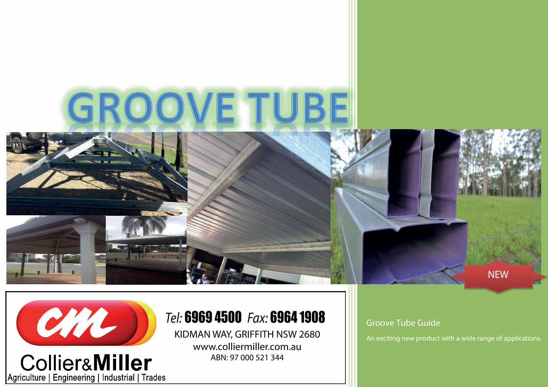
Groove Tube Guide
An exciting new product with a wide range of applications.
NEW
KIDMAN WAY, GRIFFITH NSW 2680www.colliermiller.com.au
ABN: 97 000 521 344

GROOVE TUBE SPAN TABLES FOR ATTACHED FLAT ROOF
Designation RAFTER
SPACING
MAXIMUM RAFTER SPAN (m)
WIND CATEGORY N1 N2 N3 N4 N5 N6
Design Pressures (Kpa) 0.69 0.95 1.5 2.2 3.2 4.4
100x50x1.2
900 5.0 (4.4) 4.8 (4.4) 3.8 3.2 2.6 2.2 1200 4.6 (4.1) 4.2 (4.1) 3.3 2.7 2.3 1.9 1500 4.0 (3.7) 3.4 2.7 2.2 1.8 1.6 2100 3.7 (3.6) 3.2 2.5 2.1 1.7 1.5
150x50x1.5
900 7.6 (6.0) 7.3 (6.0) 5.9 (5.4) 4.8 4.0 3.4 1200 6.9 (5.6) 6.4 (5.6) 5.1 4.2 3.4 3.0 1500 6.0 (5.0) 5.2 (5.0) 4.1 3.4 2.8 2.4 2100 5.6 (4.8) 4.8 3.8 3.1 2.6 2.2
Dimensions and Properties (Full Section) GROOVE TUBE RECTANGULAR HOLLOW SECTIONS
Groove Tube Designation
WEB
FLA
NG
E
THIC
KNE
SS
RAD
IUS Nominal
Mass per m
Perimeter Full
Section Area
2nd Moment of Area
Section Modulus Plastic Modulus Radius of Gyration
Torsion Constant
Yield Strength
Tensile Strength
D B T ri A Ix Iy Zx Zy Sx Sy rx ry J fy fu
mm mm mm mm kg/m mm mm2 106
mm4 106
mm4 103
mm3 103
mm3 103
mm3 103
mm3 mm mm 106 mm4 Mpa Mpa
1005012 100 50 1.2 1.8 2.79 298 354 0.4697 0.1614 9.394 6.457 11.51 7.14 36.5 21.4 0.3726 300 340
1505015 150 50 1.5 1.8 4.63 398 590 1.596 0.2871 21.289 11.483 27.115 12.485 52 22.1 0.7832 300 340
The above load table has been prepared for Steel Supplies to give guidance to span capabilities of Groove Tube Sections used in domestic applications applying to verandah, patio, awning and carport. Allowable spans apply to open structures as defined in the Australian Standards. Generally two or more sides are open and clear of walls. Rafters are to be connected to beams with suitable brackets through both webs of the section.
Roof pitch should not exceed 5 degrees. The above table includes a dead load of 0.1 Kpa for roof cladding and excludes any ceiling loads.
The span table is for a non trafficable roof. Span table has been designed for Wind Classification regions as indicated in AS 4055 -2006.
A deflection serviceability limit of Span/150 has been applied to the above tables. Spans shown in brackets indicate a 20mm maximum deflection limit. The table is for use in non cyclonic areas as defined in AS/NZ 1170.2 - 2002.
The structural sections comply the following Australian Standards. - AS/NZ 4600 - 2005 Cold-formed Steel Structures.
- AS/NZ 1170.1 - 2002 Structural design actions-Permanent imposed and other actions - AS/NZ 1170.1 - 2002 Structural design actions-Wind actions
-AS/NZ 4005 - 2006 Wind Loads for Housing Minimum strength steel used in above table is based on a Yield stress of 300Mpa and Tensile strength of
340Mpa. The site conditions and use of sections for design should be determined by a suitably qualified person. DISCLAIMER: The site conditions and use of sections for design should be determined by a Engineer or suitably qualified person. These tables are to be used as a guide only.
NEW
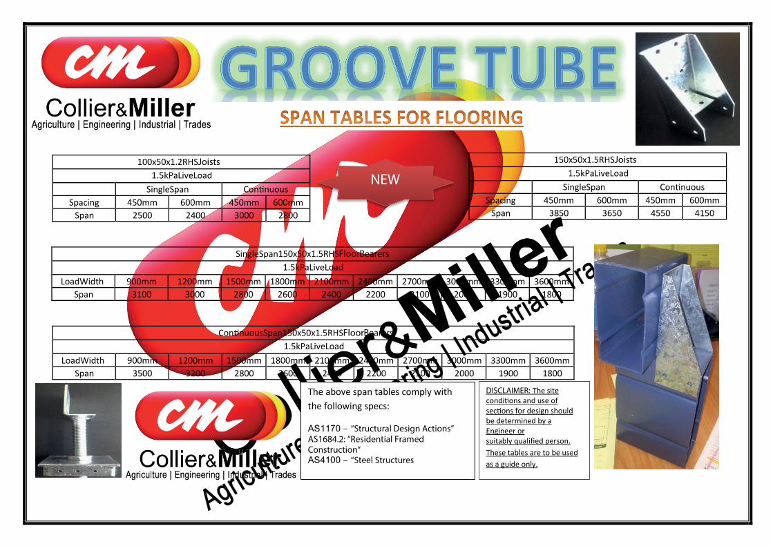
100x50x1.2 RHS Joists 1.5kPa Live Load
Single Span Continuous Spacing 450mm 600mm 450mm 600mm
Span 2500 2400 3000 2800
Single Span 150x50x1.5 RHS Floor Bearers 1.5kPa Live Load
Load Width 900mm 1200mm 1500mm 1800mm 2100mm 2400mm 2700mm 3000mm 3300mm 3600mm Span 3100 3000 2800 2600 2400 2200 2100 2000 1900 1800
Continuous Span 150x50x1.5 RHS Floor Bearers 1.5kPa Live Load
Load Width 900mm 1200mm 1500mm 1800mm 2100mm 2400mm 2700mm 3000mm 3300mm 3600mm Span 3500 3200 2800 2600 2400 2200 2100 2000 1900 1800
150x50x1.5 RHS Joists 1.5kPa Live Load
Single Span Continuous Spacing 450mm 600mm 450mm 600mm
Span 3850 3650 4550 4150
The above span tables comply with the following specs:
AS1170 – “Structural Design Actions” AS1684.2: “Residential Framed Construction” AS4100 – “Steel Structures
NEW
DISCLAIMER: The site conditions and use of sections for design should be determined by a Engineer or suitably qualified person. These tables are to be used as a guide only.

Applications for GROOVE TUBE:
FLOORING SYSTEMS SHED PURLINS PERGOLA BEAMS
PATIOS
STOCK YARDS
PROPERTY ENTRANCES FENCING ALL TYPES CONCRETE BOXING
INNOVATIVE BUILDING
100x50x1.2mm THICK x6.1M
100x50x1.2mm THICK x8M
150x50x1.5mm THICK x8M
GROOVE TUBE BRACKETS
FRAMING BRACKETS 0 - 5 DEG PITCH
FB100
FB150
ARCHITECTURAL FRAMING BRACKET
AFB10015 deg
AFB15015 deg
AFB10022.5 deg
AFB10022.5 deg
APEX BRACKET
APX10015 deg
APX15015 deg
APX10022.5 deg
APX15022.5 deg
CORNER BRACKETS
CB100
CB150
BEARER TO JOIST BRACKETS
JC100/150
FLOORING ADJUSTERS
FLA89
To fix rafters to beams or supports (mill finish)
To fix rafters to beams or support (mill finish)
External fixing of two rafters (mill finish)
NEW
For joining perimeter beams at 90� (mill finish)
For joining bearers to joists (mill finish)
Adjustable flooring to fit on 89x89 rhs (hdg finish)
**