Grid-Connected Pv-Fc Hybrid System Power Control Using Mppt And Boost Converter
GRID CONNECTED PV SYSTEM USING MPPT
Vipra Joshi,Pushpinder kaur
PG Student, Faculty of Technology,UTU campus,Dehradun-248007,India
ABSTRACT-In this paper presents analysis of grid connected PV system with maximum
power point tracking (MPPT) control.Grid interconnection of photovoltaic (PV) power
generation systems has the advantage of effective utilization of generated power because there
are no storage losses involved.Grid-connected photovoltaic system simulates in
MATLAB/Simulink.The key technology of a PV system includes PV cell modeling, maximum
power point tracking (MPPT) algorithm, DC/DC converter and grid-connected DC/AC
inverter.MPPT is used for extracting the maximum power from the PV cell and transferring that
power to the load.A DC/DC converter acts as an interface between the load and the PV cell. It
used for transferring maximum power from the solar PV cellto load. The DC/AC Inverter is used
to regulate the output voltage of DC/DC converter and connects the PV cell with DC/DC
converter to the grid. The output voltage is required to be sinusoidal and in phase with the grid
voltage.
keywords—photovoltaic system, MPPT, grid-connected
INTRODUCTION
Among a variety of renewable energy
sources, solar energy is predicted to become
the largest contributors to world energy for
its clean and no supply limitations
characteristic. Over the past decade, PV
technology has shown the potential by
robust and continuous growth even during
times of financial crisis. Grid
interconnection of photovoltatic (PV) power
generation system has the advantage of more
effective utilization of generated power.
As day by day the demand of electricity is
increased and that much demand cannot be
meeting up by the conventional power plant.
And also these power plants create
pollution. If we look at the nature of load
demand curve it is found that demand is
increased from morning for different causes
like opening the shops, markets, schools,
colleges, offices etc and that increases
demand remains upto around 5 PM, and
from the study of the PV system it is found
that, it is very much ideal to meet that
increased energy demand by using grid
connected PV. That’s why we go for grid connected topology.
Grid interconnected photovoltatic system is
accomplished through the inverter,which
convert DC power generated from
PVmodules to AC power used for ordinary
power supply for electrical equipments.
Inverter system is therefore very important
for grid connected PV system. It is also
required to generate high quality power to
AC utility system with reasonable cost. By
mean of high frequency switching of
semiconductor device with PWM(Pulse
width modulation) technologies, high power
factor and low harmonic distortion power
can be generated.
The key technology of a PV system includes
PV cell modeling, maximum power point
tracking (MPPT) algorithm, DC/DC
converter and grid-connected DC/AC
inverter.
International Journal of Scientific & Engineering Research, Volume 6, Issue 5, May-2015 ISSN 2229-5518
156
IJSER © 2015 http://www.ijser.org
IJSER
MODELING OF PHOTOVOLTAIC CELL
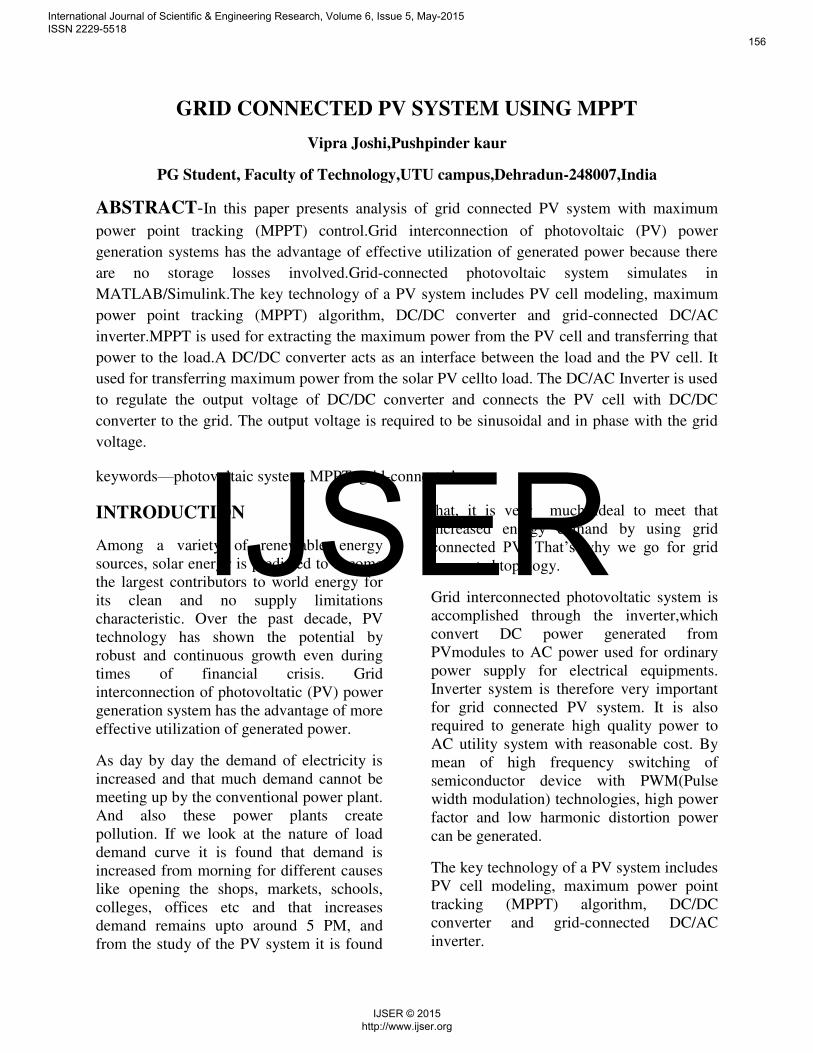
(I)- Ideal PV Cell
Photovoltaic (PV) cell is a semiconductor
device that absorbs and converts the energy
of light into electricity by photovoltaic
effect.
Figure1-
Equivalent circuit of ideal PV cell
The voltage-current characteristic equation
of a solar cell is given as(1)
= h−[exp( (�+ � )/����)−1]–(�+ � )/� h (1)
Where,Ish is a light-generated current or
photocurrent
I is the cell saturation of dark current,
q (= 1.6 ×10⁻¹⁹ C) is an electron charge,
k (= 1.38 ×10⁻²³J/K) is a Boltzmann’s constant,
Tc is the cell’s working temperature,A is an ideal factor,
Rsh is a Shunt resistance, and Rs is a series
resistance of solar cell.The photocurrent
mainly depends on the solar insolation and
cell’s working temperature,which is
described as(2)
h = [ � + �(��–� )] (2) ,Where Isc is
the cells short-circuit current at a 25°C and
1kW/m2,Ki is the cell’s short-circuit current
temperature coefficient,
Tref is the cell’s reference temperature, andH is the solar insolation in kW/m2.
On the other hand, the cell’s saturation current varies with the cell temperature,
which isdescribed as
= (��/� )^3 exp[( � (�� − � )
/� ����] (3)
Where,Irs is the cell’s reverse saturation current at a reference temperature and
standard solarradiation.
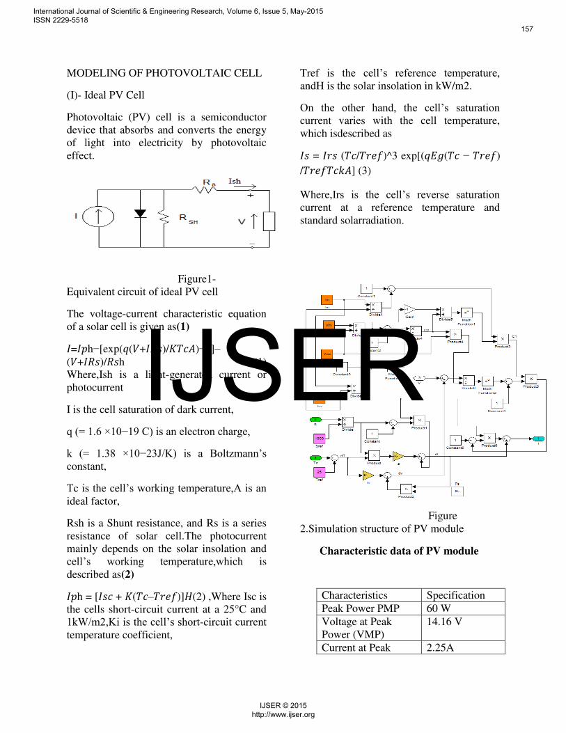
Figure
2.Simulation structure of PV module
Characteristic data of PV module
Characteristics Specification
Peak Power PMP 60 W
Voltage at Peak
Power (VMP)
14.16 V
Current at Peak 2.25A
International Journal of Scientific & Engineering Research, Volume 6, Issue 5, May-2015 ISSN 2229-5518
157
IJSER © 2015 http://www.ijser.org
IJSER
Power(IMP)
Short Circuit
Current(ISC)
2..55 A
Open Circuit
Voltage(VOC)
17.1 V
Temperature Co-
efficient Of Short
Circuit Current(K)
0.0017 A/°C
MPPT CONTROL ALGORITHM
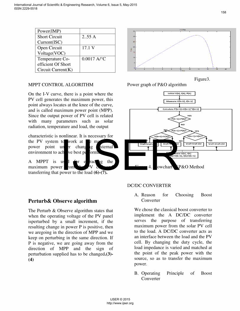
On the I-V curve, there is a point where the
PV cell generates the maximum power, this
point always locates at the knee of the curve,
and is called maximum power point (MPP).
Since the output power of PV cell is related
with many parameters such as solar
radiation, temperature and load, the output
characteristic is nonlinear. It is necessary for
the PV system to work at the maximum
power point under changing external
environment to achieve best performance.
A MPPT is used for extracting the
maximum power from the PV cell and
transferring that power to the load (6)-(7).
Perturb& Observe algorithm
The Perturb & Observe algorithm states that
when the operating voltage of the PV panel
isperturbed by a small increment, if the
resulting change in power P is positive, then
we aregoing in the direction of MPP and we
keep on perturbing in the same direction. If
P is negative, we are going away from the
direction of MPP and the sign of
perturbation supplied has to be changed.(3)-
(4)
Figure3.
Power graph of P&O algorithm
Figure 4. Flowchart of P&O Method
DC/DC CONVERTER
A. Reason for Choosing Boost
Converter
We chose the classical boost converter to
implement the A DC/DC converter
serves the purpose of transferring
maximum power from the solar PV cell
to the load. A DC/DC converter acts as
an interface between the load and the PV
cell. By changing the duty cycle, the
load impedance is varied and matched at
the point of the peak power with the
source, so as to transfer the maximum
power.
B. Operating Principle of Boost
Converter
International Journal of Scientific & Engineering Research, Volume 6, Issue 5, May-2015 ISSN 2229-5518
158
IJSER © 2015 http://www.ijser.org
IJSER

Figure5 shows the topology of Boost
converter. For this converter, power
flow is controlled by means of the
on/off duty cycle of the switching
transistor. When the switch is OnTon
for seconds, current flows through
the inductor in clockwise, and energy
Vi I1Toff is storedDC/DC
CONVERTER
A DC/DC converter serves the purpose of
transferring maximum power from the solar
PV cell to the load. A DC/DC converter acts
as an interface between the load and the PV
cell. By changing the duty cycle, the load
impedance is varied and matched at the
point of the peak power with the source, so
as to transfer the maximum power. When
the switch is Off Toff for seconds, current
will be reduced for increasing impedance.
The only path of the inductor current is
through diode D to the capacitor C and load
R. The polarity of inductor will change. And
the energy accumulated in the inductor
during the On-State will be released,
Where D is the duty cycle. It represents the
fraction of the commutation period T during
which the switch is On. Since, the
output voltage is always higher than the
source voltage.
Figure.5 Circuit diagram of boost converter
C. Simulation of DC/DC Converter with
MPPT algorithm in MATLAB/Simulink
TABLE II
PARAMETERS OF THE DC/DC
CONVERTER
Parameter
Value
Inductor L
0.01
H
Capacitor
C1
2*10-
3 F
Capacitor
C
2*10-
3 F
Resistor R
2*10-
3 F
Figure6.Simulation Model for DC/DC
converter
International Journal of Scientific & Engineering Research, Volume 6, Issue 5, May-2015 ISSN 2229-5518
159
IJSER © 2015 http://www.ijser.org
IJSER

Figure7.Output power of PV module
Figure8.
Load output power using MPPT
DC/AC INVERTER
The DC/AC Inverter is used to regulate the
output voltage of DC/DC converter and
connects the PV cell with DC/DC converter
to the grid. The output voltage is required to
be sinusoidal and in phase with the grid
voltage. Figure11 shows the whole PV grid-
connected system.The PWM signal can be
usedtocontrol switches of DC/AC inverter.
The frequency of PWM waveform is set as 5
kHz, which can reduce the switching noise,
simplify the system design and improve the
dynamic performance.
Figure9. Whole PV Grid-Connected System
Simulation result when temperature and solar radiation keeps unchanged,T=25 c, S=1000 w/m^2
CONCLUSION
Grid connected PV system with MPPT
system, it can be concluded that,this model
can work well under sudden change of
environment temperature or solar radiation.
The maximum power of the PV cell is
tracked with an adjusted P&O MPPT
algorithm based on Boost DC/DC converter.
A DC/AC inverter has beenused to connect
the PV cell to the grid and regulate the
output voltage of DC/DC converter. The
whole pv grid-connected system is
simulated in MATLAB/Simulink. Special
situations such as sudden change of
temperature and solar radiation have been
simulated and analyzed.
REFERENCES
1-H. S. Rauschenbach, Solar Cell Array
Design Handbook.NewYork, Van Nostrand
Reinhold, 1980
2-Su Jianhui; Yu Shijie; Zhao Wei; Wu
Minda; ShenYuliang; He Huiruo.
Investigation on Engineering
Analytical Model of Silicon Solar Cells
[J].ActaEnergiae Solaris Sinica, 2001, 6(22):
439-412
International Journal of Scientific & Engineering Research, Volume 6, Issue 5, May-2015 ISSN 2229-5518
160
IJSER © 2015 http://www.ijser.org
IJSER
3- J. J. Nedumgatt, K. B. Jayakrishnan, S.
Umashankar, D. Vijayakumar, and D. P.
Kothari, “Perturb and Observe MPPT Algorithm for Solar PV Systems-modeling
and Simulation,” in Annual IEEE India Conference (INDICON), Dec. 2011, pp. 1–6.
4- L. Chun-xia and L. Li-qun, “An Improved Perturbation and Observation MPPT Method
of Photovoltaic Generate System,” in 4th IEEE
5-M.E.Ahmad and S.Mekhilef, "Design and
Implementation of a Multi Level Three-
Phase Inverter with Less Switches and Low
Output Voltage Distortation," Journal of
Power Electronics, vol. 9, pp. 594-604, 2009
6- S. Chin, J. Gadson, and K. Nordstrom,
"Maximum Power Point Tracker," Tufts
University Department of Electrical
Engineering and Computer Science, 2003,
pp. 1-66.
7- UL1741, Inverter, Converter, and
Controllers for Use in Independent Power
System.
8-M. A. S. Masoum, H. Dehbonei, and E. F.
Fuchs, “Theoretical and Experimental Analyses of Photovoltaic Systems with
Voltage and Current-based Maximum
Power-Point Tracking,” IEEE Trans. on Energy Converters., vol. 17, no. 4, pp. 514–522, Dec. 2002.
International Journal of Scientific & Engineering Research, Volume 6, Issue 5, May-2015 ISSN 2229-5518
161
IJSER © 2015 http://www.ijser.org
IJSER