Grid-Connected Modular Soft-Switching Solid State ...
1
www.cde.gatech.edu Objective: Develop a solid-state transformer based on single-stage soft-switching solid-state transformer modules with low dv/dt and low EMI. ▪ Standard 60 Hz transformers are robust and inexpensive with an expected life of 40 years, but cannot provide control of voltage, current, VARs etc. ▪ Developing a solid state transformer (SST), as a replacement for the 60 hertz ‘service transformer’ has been tried but remains challenging. ▪ State-of-art designs are based on complex multi-stage conversion. ▪ High voltage switching devices ( > 3.3 kV) are necessary to realize a SST at medium voltages. ▪ 3.3 kV Si IGBTs are typically limited to switching frequencies of <1 kHz making SSTs large, bulky, impractical and expensive. ▪ Replacing the Si devices with Silicon Carbide (SiC) devices, creates other issues such as high parasitic currents and high EMI. ▪ No practical and cost-effective solution yet to meeting the BIL rating necessary for grid connected converters, or to manage downstream faults. Grid-Connected Modular Soft-Switching Solid State Transformers (M-S4T) PI: Deepak Divan Introduction Proposed Approach 7.2 kV HV Insulation Barrier with 110 kv BIL Series stacked modules Parallel connected modules 50 kVA 7.2 kV/ 240 V M-S4T 240 V AC/ 200 A or 360 V DC/ 140 A 7 A SST topology based on DAB converter Multi-stage conversion = = = = Dual Active Bridge Active Rectifier Inverter DC Link DC Link HF-XFMR ▪ Single stage converter with HF isolation ▪ Universal – AC or DC input/output with bi-directional power flow ▪ Current source converter – better fault current management ▪ Soft switching over entire range – high efficiency ▪ Controlled dv/dt - low EMI ▪ Modular design - scaling to high power and high voltage ▪ Use SiC devices (3.3 kV) to enable direct connection to medium voltage grid (4 kV – 13 kV) Unique features Schematic of the soft- switching solid-state transformer Schematic of the 90 kV BIL test setup 90 kV Basic Insulation Level Test Modular Soft Switching Solid-State Transformer Prototype and Experimental Results ▪ The 7.2 kV 50 kVA prototype with passive (oil) cooling has been built. ▪ Single 10 kVA converter module has been tested up to 1.44 kV 7 kW. ▪ The prototype has been tested up to 5.3 kV 20 kVA. ▪ Magnetizing current is regulated about its reference. ▪ MV AC voltage has THD < 5% and 7.5 kV peak. ▪ 120Hz power ripple is dumped into the buffer capacitor bank. ▪ ZVS is achieved for significantly reduced switching loss. ▪ Dv/dt is controlled to be less than 800V/us. ZVS and dv/dt control is achieved. Xfmr LV winding current 50A/div Xfmr HV winding current 10A/div MVAC voltage 1kV/div LVDC voltage 200V/div Buffer capacitor voltage 200V/div LV resonant capacitor voltage 200V/div HV resonant capacitor voltage 1kV/div Contactor 480V Variac 480V 3-Phase Supply 480V Rectifier Yg-Y LV Bridge HF Transformer MV Bridge 300VDC-1.44kVAC S4T MV Load Bank Contactor 7.2 kV 50 kVA prototype Schematic of the test setup in the HV cell. BIL management stage High-frequency transformer itself passed 55kV impulse test. • A BIL management stage has been developed to handle 90 kV BIL – limit the converter input voltage to be < 15 kV. • The converter, represented by input capacitors, was tested with standard 90 kV impulse • The voltage at the converter was measured to be 13.1 kV under 90 kV impulse conditions. Voltage measured along BIL management stage and converter input Test setup in the HV cell The prototype has been tested up to 7.5 kV peak 20 kVA. Full load range ZVS and controlled dv/dt are verified. 7.5 kV peak 20 kVA line-cycle waveform 1.5 kV to 4 kV peak step-up waveform Switching-cycle waveform 16kHz nano crystalline core transformer for the 10kVA converter module. Transformer BIL test voltage waveform Georgia Institute of Technology, EPRI & Southern Company Converter passed 90 kV BIL test Tech-To-Market Conventional DC Fast Charging M-S4T Approach • M-S4T is suited for applications where isolation and 1 or 2 converters are needed, or for grid-connected converters: ▪ PV/Battery/Grid multi-port converters ▪ MV distribution in ships ▪ PV farms ▪ Data centers • Main Value: Size and efficiency gains; higher performance; smaller size. T2M Challenges M-S4T Applications T2M Approach Load Resistor Rectifier Prototype Module 1 MVAC output voltage 500 V/div Module 1 MVAC output voltage 500 V/div Module 1 MVAC output voltage 500 V/div Module 1 MVAC output voltage 500 V/div Module 1 MVAC output voltage 500 V/div 10 ms/div Module 1 MVAC output voltage 2 kV/div Module 1 MVAC output voltage 2 kV/div Module 1 MVAC output voltage 2 kV/div Module 1 MVAC output voltage 2 kV/div Module 1 MVAC output voltage 2 kV/div 5 ms/div Buffer capacitor voltage 200 V/div Combined efficiency of LV xmr + 2 converters – 91%. Combined efficiency 96-97%. Size gains due to transformer integration. Conclusion • Major challenge for commercialization ->3.3 kV SiC device cost ▪ Si IGBT @1700 V - $0.12/KVA ▪ Si IGBT + SiC Custom RB module - $0.58/KVA ▪ SiC @3300 V - $17.5/KVA • Conventional approach – estimated price $36,000 for 100 kW system ▪ LV transformer+ AC/DC converter + DC/DC converter with HF isolation ▪ 92% efficiency (97% Xmr x 97 % AC/DC converter x 98% DC/DC converter) ▪ ($25/kVA Xmr + $150/kVA AC/DC + $100/KVA DC/DC with HF isolation)*1.3 (integration cost) • M-S4T approach: To be viable M-S4T must be at <$18000 (BOM cost) ▪ HF Transformers - $2000, LV semiconductors cost - $4000, Cabinet + Controller + Peripherals - $6000 ▪ Surge protection - $1000, 3.3 kV SiC semiconductors (3000 kVA) has to be < $5000 instead of $52,000 • Multiple applications identified as viable with for SiC device cost reduction. • Interest from multiple end-users, but limited by SiC device cost issues. Aug, 2019 Updated Navy on potential application of S4T for MVDC distribution on ships May 2018 Paid NRE costs of $125K for custom RB 3.3 kV modules Feb 2019 Paid NRE to develop custom Litz coax with 60 kV BIL Nov 2019 Working with Southern Company on DC fast charging but with LV S4T Sep, 2020 At the end of the project will pursue funding to develop MVDC converters for Navy 2020 Will pursue funding from SoCo for DC fast charging with grid direct connected S4T Expensive 3.3 kV customized SiC module • Major challenges in realizing solid state transformers that have been addressed: BIL and insulation coordination, control of series stacked low-inertia converters, low EMI even with fast switching 3.3 kV SiC devices. • An experimental prototype has been built and tested up to 7.5 kV peak 20 kVA. • Potential applications and T2M are limited by high cost of SiC modules. 3.3 kV semiconductor needs to be at $1.7/kVA, as opposed to $17.5/KVA
Transcript of Grid-Connected Modular Soft-Switching Solid State ...
www.cde.gatech.edu
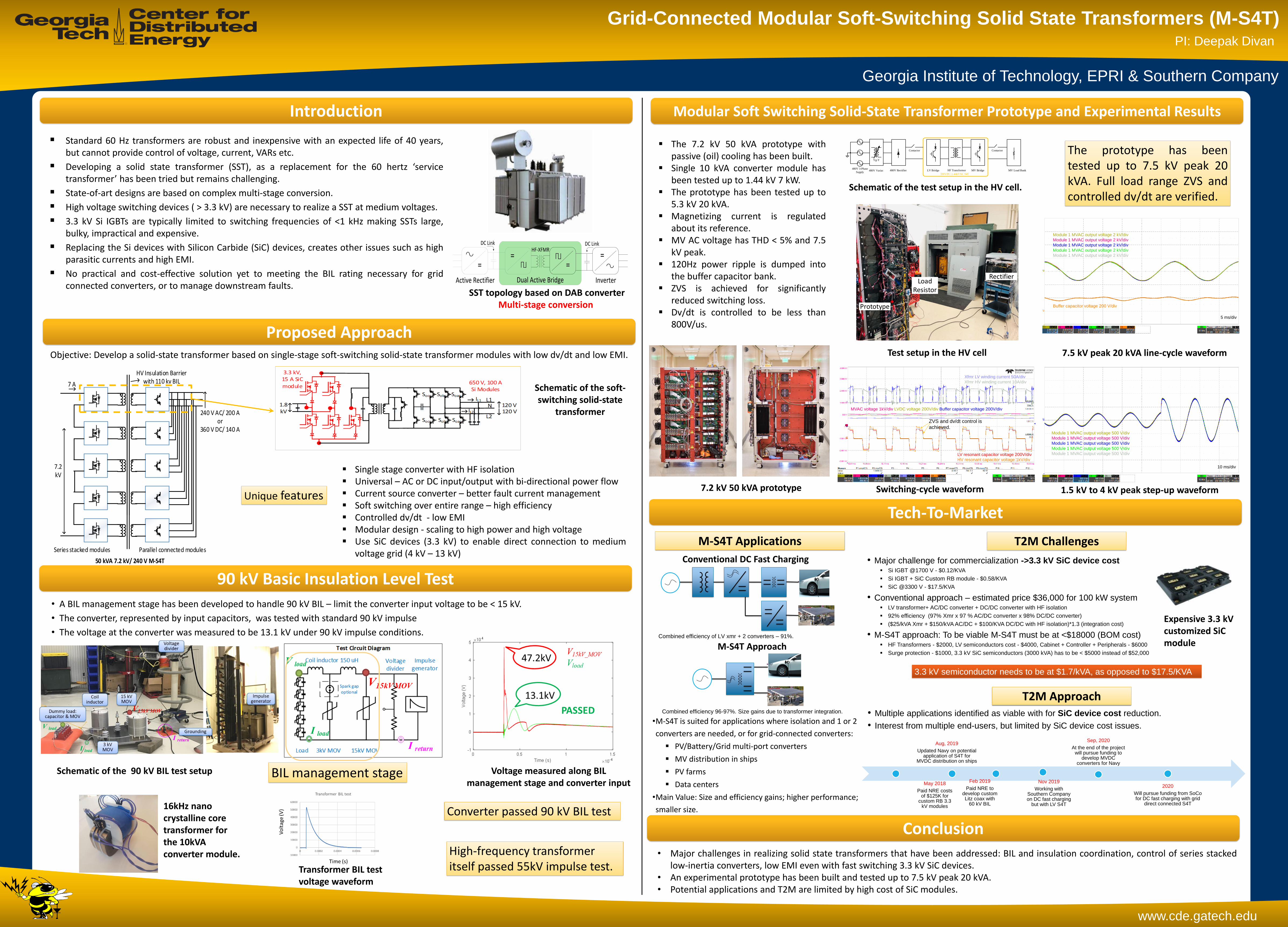
Objective: Develop a solid-state transformer based on single-stage soft-switching solid-state transformer modules with low dv/dt and low EMI.
▪ Standard 60 Hz transformers are robust and inexpensive with an expected life of 40 years,but cannot provide control of voltage, current, VARs etc.
▪ Developing a solid state transformer (SST), as a replacement for the 60 hertz ‘servicetransformer’ has been tried but remains challenging.
▪ State-of-art designs are based on complex multi-stage conversion.
▪ High voltage switching devices ( > 3.3 kV) are necessary to realize a SST at medium voltages.
▪ 3.3 kV Si IGBTs are typically limited to switching frequencies of <1 kHz making SSTs large,bulky, impractical and expensive.
▪ Replacing the Si devices with Silicon Carbide (SiC) devices, creates other issues such as highparasitic currents and high EMI.
▪ No practical and cost-effective solution yet to meeting the BIL rating necessary for gridconnected converters, or to manage downstream faults.
Grid-Connected Modular Soft-Switching Solid State Transformers (M-S4T)PI: Deepak Divan
Introduction
Proposed Approach
7.2 kV
HV Insulation Barrier with 110 kv BIL
Series stacked modules Parallel connected modules
50 kVA 7.2 kV/ 240 V M-S4T
240 V AC/ 200 A or
360 V DC/ 140 A
7 A
SST topology based on DAB converterMulti-stage conversion
==
==
Dual Active BridgeActive Rectifier Inverter
DC Link DC LinkHF-XFMR
▪ Single stage converter with HF isolation▪ Universal – AC or DC input/output with bi-directional power flow▪ Current source converter – better fault current management▪ Soft switching over entire range – high efficiency▪ Controlled dv/dt - low EMI▪ Modular design - scaling to high power and high voltage▪ Use SiC devices (3.3 kV) to enable direct connection to medium
voltage grid (4 kV – 13 kV)
Unique features
Schematic of the soft-switching solid-state
transformer
Schematic of the 90 kV BIL test setup
90 kV Basic Insulation Level Test
Modular Soft Switching Solid-State Transformer Prototype and Experimental Results
▪ The 7.2 kV 50 kVA prototype withpassive (oil) cooling has been built.
▪ Single 10 kVA converter module hasbeen tested up to 1.44 kV 7 kW.
▪ The prototype has been tested up to5.3 kV 20 kVA.
▪ Magnetizing current is regulatedabout its reference.
▪ MV AC voltage has THD < 5% and 7.5kV peak.
▪ 120Hz power ripple is dumped intothe buffer capacitor bank.
▪ ZVS is achieved for significantlyreduced switching loss.
▪ Dv/dt is controlled to be less than800V/us.
ZVS and dv/dt control is
achieved.
Xfmr LV winding current 50A/div
Xfmr HV winding current 10A/div
MVAC voltage 1kV/div LVDC voltage 200V/div Buffer capacitor voltage 200V/div
LV resonant capacitor voltage 200V/div
HV resonant capacitor voltage 1kV/div
Contactor
480V Variac480V 3-Phase
Supply480V Rectifier
Yg-Y
LV Bridge HF Transformer MV Bridge
300VDC-1.44kVAC S4T
MV Load Bank
Contactor
7.2 kV 50 kVA prototype
Schematic of the test setup in the HV cell.
BIL management stage
High-frequency transformer itself passed 55kV impulse test.
• A BIL management stage has been developed to handle 90 kV BIL – limit the converter input voltage to be < 15 kV.
• The converter, represented by input capacitors, was tested with standard 90 kV impulse
• The voltage at the converter was measured to be 13.1 kV under 90 kV impulse conditions.
Voltage measured along BIL management stage and converter input
Test setup in the HV cell
The prototype has beentested up to 7.5 kV peak 20kVA. Full load range ZVS andcontrolled dv/dt are verified.
7.5 kV peak 20 kVA line-cycle waveform
1.5 kV to 4 kV peak step-up waveformSwitching-cycle waveform
16kHz nanocrystalline core transformer for the 10kVA converter module.
Transformer BIL test voltage waveform
Georgia Institute of Technology, EPRI & Southern Company
Converter passed 90 kV BIL test
Tech-To-Market
Conventional DC Fast Charging
M-S4T Approach
•M-S4T is suited for applications where isolation and 1 or 2
converters are needed, or for grid-connected converters:
▪ PV/Battery/Grid multi-port converters
▪ MV distribution in ships
▪ PV farms
▪ Data centers
•Main Value: Size and efficiency gains; higher performance;
smaller size.
T2M ChallengesM-S4T Applications
T2M Approach
Load Resistor
Rectifier
Prototype
LV Bridge
MV Bridge
Transformer LV busbar
Module 1 MVAC output voltage 500 V/div
Module 1 MVAC output voltage 500 V/div
Module 1 MVAC output voltage 500 V/div
Module 1 MVAC output voltage 500 V/div
Module 1 MVAC output voltage 500 V/div
10 ms/div
Module 1 MVAC output voltage 2 kV/div
Module 1 MVAC output voltage 2 kV/div
Module 1 MVAC output voltage 2 kV/div
Module 1 MVAC output voltage 2 kV/div
Module 1 MVAC output voltage 2 kV/div
5 ms/div
Buffer capacitor voltage 200 V/div
Combined efficiency of LV xmr + 2 converters – 91%.
Combined efficiency 96-97%. Size gains due to transformer integration.
Conclusion
• Major challenge for commercialization ->3.3 kV SiC device cost▪ Si IGBT @1700 V - $0.12/KVA
▪ Si IGBT + SiC Custom RB module - $0.58/KVA
▪ SiC @3300 V - $17.5/KVA
• Conventional approach – estimated price $36,000 for 100 kW system▪ LV transformer+ AC/DC converter + DC/DC converter with HF isolation
▪ 92% efficiency (97% Xmr x 97 % AC/DC converter x 98% DC/DC converter)
▪ ($25/kVA Xmr + $150/kVA AC/DC + $100/KVA DC/DC with HF isolation)*1.3 (integration cost)
• M-S4T approach: To be viable M-S4T must be at <$18000 (BOM cost) ▪ HF Transformers - $2000, LV semiconductors cost - $4000, Cabinet + Controller + Peripherals - $6000
▪ Surge protection - $1000, 3.3 kV SiC semiconductors (3000 kVA) has to be < $5000 instead of $52,000
• Multiple applications identified as viable with for SiC device cost reduction.
• Interest from multiple end-users, but limited by SiC device cost issues.
Aug, 2019
Updated Navy on potential application of S4T for
MVDC distribution on ships
May 2018
Paid NRE costs of $125K for
custom RB 3.3 kV modules
Feb 2019
Paid NRE to develop custom Litz coax with
60 kV BIL
Nov 2019
Working with Southern Company on DC fast charging
but with LV S4T
Sep, 2020
At the end of the project will pursue funding to
develop MVDC converters for Navy
2020
Will pursue funding from SoCofor DC fast charging with grid
direct connected S4T
Expensive 3.3 kV customized SiCmodule
• Major challenges in realizing solid state transformers that have been addressed: BIL and insulation coordination, control of series stackedlow-inertia converters, low EMI even with fast switching 3.3 kV SiC devices.
• An experimental prototype has been built and tested up to 7.5 kV peak 20 kVA.• Potential applications and T2M are limited by high cost of SiC modules.
3.3 kV semiconductor needs to be at $1.7/kVA, as opposed to $17.5/KVA