Gresen GRS32 Calibration
17
12/21/2009 Page 1 Gresen Calibration Guide for Mn/DOT by EVS Gresen GRS32 Calibration (also see the MnDOT Salt and Sander Calibration Guide for general calibration reference)
Transcript of Gresen GRS32 Calibration
12/21/2009 Page 1 Gresen Calibration Guide for Mn/DOT by EVS
Gresen GRS32
Calibration
(also see the MnDOT Salt and Sander Calibration Guide for
general calibration reference)
12/21/2009 Page 2 Gresen Calibration Guide for Mn/DOT by EVS
Gresen GRS32 Calibration
Table of Contents
Controller Components
Tricks and Traps
Preliminary Setup
Getting Started
Entering Calibrate Mode
Granular Materials Calibration (Catch Test)
Appendix - Ground Speed Calibration
Appendix - Calibrating the Auger Valve
Appendix - Calibrating the Spinner Valve
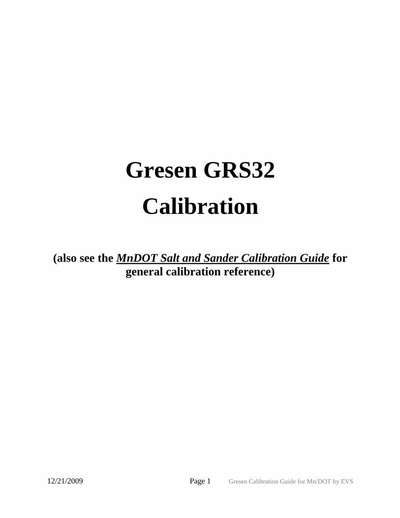
Controller Components
Gresen GRS32 Controller Components
12/21/2009 Page 3 Gresen Calibration Guide for Mn/DOT by EVS
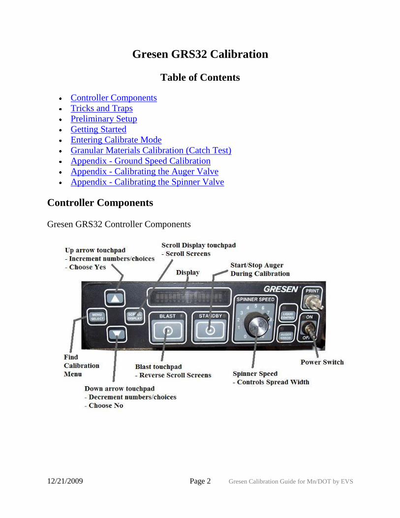
Tricks and Traps
Description
Scroll numbers/options - Use the up and down
arrows
Scroll calibration screens - Use 'Scroll Display'
touchpad button
Reverse-Scroll calibration screens - Use Blast
touchpad button
Change 'N' (no) to 'Y' (yes) - Use up arrow. Also
hold down for fast scroll.
Change 'Y' (yes) to 'N' (no) - Use down arrow. Also
hold down for fast scroll.
12/21/2009 Page 4 Gresen Calibration Guide for Mn/DOT by EVS
Preliminary Setup
Step Description
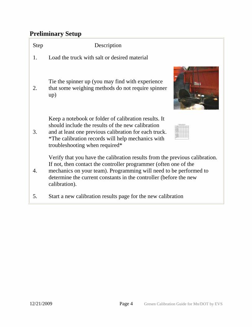
1. Load the truck with salt or desired material
2.
Tie the spinner up (you may find with experience
that some weighing methods do not require spinner
up)
3.
Keep a notebook or folder of calibration results. It
should include the results of the new calibration
and at least one previous calibration for each truck.
*The calibration records will help mechanics with
troubleshooting when required*
4.
Verify that you have the calibration results from the previous calibration.
If not, then contact the controller programmer (often one of the
mechanics on your team). Programming will need to be performed to
determine the current constants in the controller (before the new
calibration).
5. Start a new calibration results page for the new calibration
12/21/2009 Page 5 Gresen Calibration Guide for Mn/DOT by EVS
Getting Started
Step Description
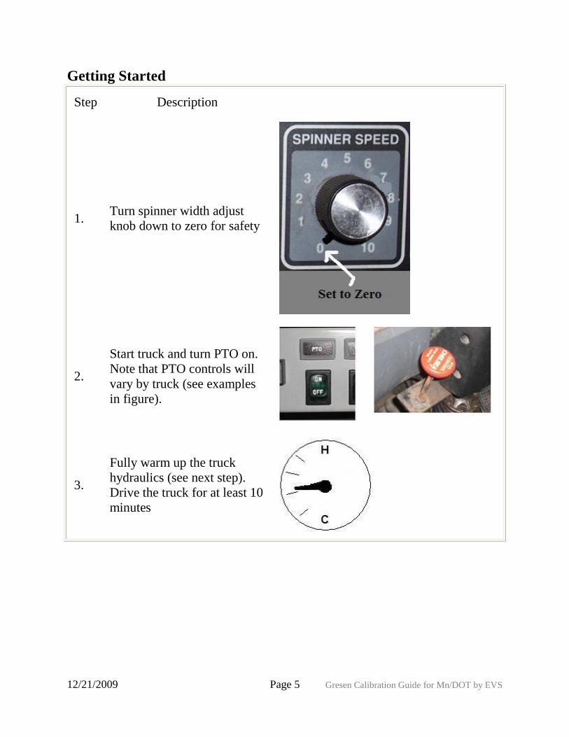
1. Turn spinner width adjust
knob down to zero for safety
2.
Start truck and turn PTO on.
Note that PTO controls will
vary by truck (see examples
in figure).
3.
Fully warm up the truck
hydraulics (see next step).
Drive the truck for at least 10
minutes
12/21/2009 Page 6 Gresen Calibration Guide for Mn/DOT by EVS
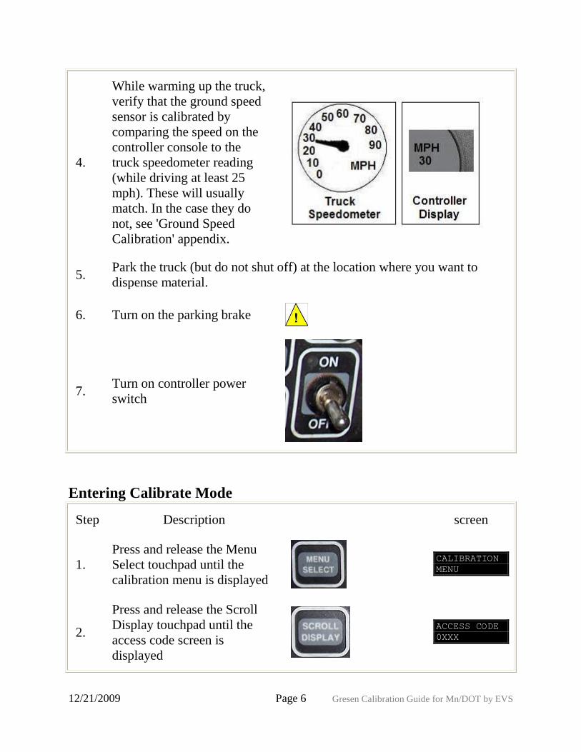
4.
While warming up the truck,
verify that the ground speed
sensor is calibrated by
comparing the speed on the
controller console to the
truck speedometer reading
(while driving at least 25
mph). These will usually
match. In the case they do
not, see 'Ground Speed
Calibration' appendix.
5. Park the truck (but do not shut off) at the location where you want to
dispense material.
6. Turn on the parking brake
7. Turn on controller power
switch
Entering Calibrate Mode
Step Description screen
1.
Press and release the Menu
Select touchpad until the
calibration menu is displayed
CALIBRATION
MENU
2.
Press and release the Scroll
Display touchpad until the
access code screen is
displayed
ACCESS CODE
0XXX
12/21/2009 Page 7 Gresen Calibration Guide for Mn/DOT by EVS
3. Press the arrow touchpads to
change first digit
ACCESS CODE
0XXX
4.
Press the Scroll Display
touchpad to move to the next
digit of the code
ACCESS CODE
X0XX
5. Press the arrow touchpads to
change digit
ACCESS CODE
X0XX
6. Repeat steps 4 and 5 until all
four digits have been entered
Granular Materials Calibration (Catch Test)
Step Description screen
Catch Test - Calibrating for materials
1.
Press and release the
Scroll Display touchpad
until the 'MATL RATES
A' screen is displayed
MATL RATES
A? N
2. Press the up arrow to
change the 'N' to 'Y'
MATL RATES
A? Y
Note: this procedure assumes an auger system
12/21/2009 Page 8 Gresen Calibration Guide for Mn/DOT by EVS
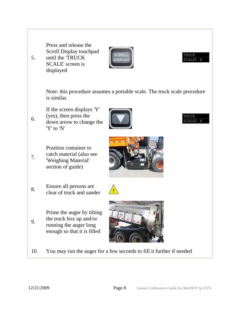
5.
Press and release the
Scroll Display touchpad
until the 'TRUCK
SCALE' screen is
displayed
TRUCK
SCALE? N
Note: this procedure assumes a portable scale. The truck scale procedure
is similar.
6.
If the screen displays 'Y'
(yes), then press the
down arrow to change the
'Y' to 'N'
TRUCK
SCALE? N
7.
Position container to
catch material (also see
'Weighing Material'
section of guide)
8. Ensure all persons are
clear of truck and sander
9.
Prime the auger by tilting
the truck box up and/or
running the auger long
enough so that it is filled
10. You may run the auger for a few seconds to fill it further if needed
12/21/2009 Page 9 Gresen Calibration Guide for Mn/DOT by EVS
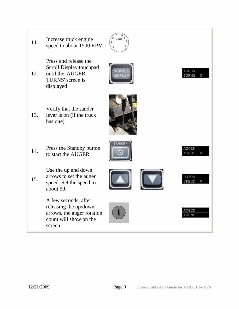
11. Increase truck engine
speed to about 1500 RPM
12.
Press and release the
Scroll Display touchpad
until the 'AUGER
TURNS' screen is
displayed
AUGER
TURNS 0
13.
Verify that the sander
lever is on (if the truck
has one)
14. Press the Standby button
to start the AUGER
AUGER
TURNS 0
15.
Use the up and down
arrows to set the auger
speed. Set the speed to
about 50.
MOTOR
SPEED 0
A few seconds, after
releasing the up/down
arrows, the auger rotation
count will show on the
screen
AUGER
TURNS 1
12/21/2009 Page 10 Gresen Calibration Guide for Mn/DOT by EVS
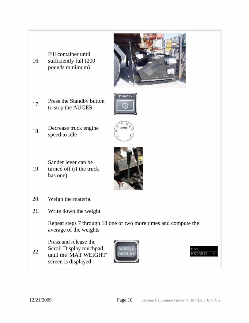
16.
Fill container until
sufficiently full (200
pounds minimum)
17. Press the Standby button
to stop the AUGER
18. Decrease truck engine
speed to idle
19.
Sander lever can be
turned off (if the truck
has one)
20. Weigh the material
21. Write down the weight
Repeat steps 7 through 18 one or two more times and compute the
average of the weights
22.
Press and release the
Scroll Display touchpad
until the 'MAT WEIGHT'
screen is displayed
MAT
WEIGHT? 0
12/21/2009 Page 11 Gresen Calibration Guide for Mn/DOT by EVS
23.
Use the up and down
arrows to enter the
average weight
MAT
WEIGHT? 0
24.
Press and release the
Scroll Display touchpad
until the 'CALCULATE'
screen is displayed
CALCULATE?
N
25. Press the up arrow to
change the 'N' to 'Y'
CALCULATE?
Y
26. The screen will display that the calibration is done CALCULATE?
DONE
27. Press Scroll Display to view LBS/REV. Record value. LBS/REV
28.
If more material types are
used, repeat these
procedure for materials
using i.e. menu 'MATL
RATES B', etc.
MATL RATES
B? Y
Appendix - Ground Speed Calibration
Step Description screen
Also see 'Getting Started' section to determine if ground speed calibration
is required. This calibration is only required if truck speedometer does
not match speed shown on controller screen.
1.
Press and release the Scroll
Display touchpad until the
'CAL GND SPEED' screen
is displayed
CAL GND
SPEED? N
12/21/2009 Page 12 Gresen Calibration Guide for Mn/DOT by EVS
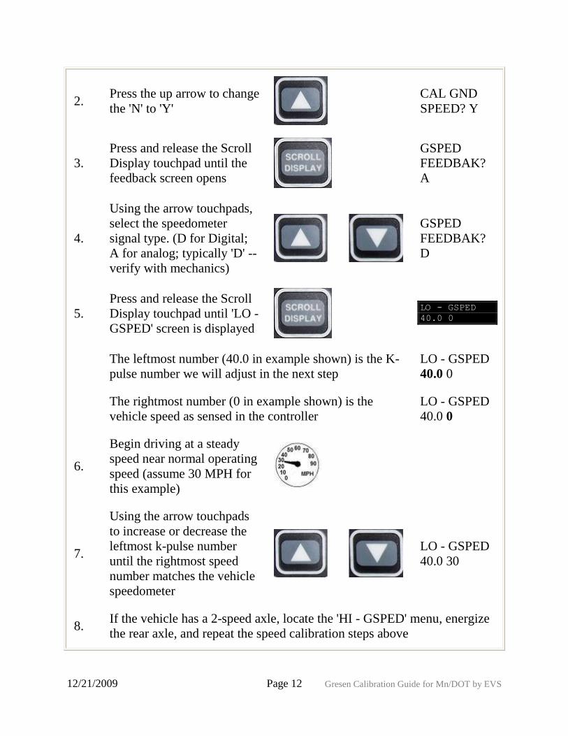
2. Press the up arrow to change
the 'N' to 'Y'
CAL GND
SPEED? Y
3.
Press and release the Scroll
Display touchpad until the
feedback screen opens
GSPED
FEEDBAK?
A
4.
Using the arrow touchpads,
select the speedometer
signal type. (D for Digital;
A for analog; typically 'D' --
verify with mechanics)
GSPED
FEEDBAK?
D
5.
Press and release the Scroll
Display touchpad until 'LO -
GSPED' screen is displayed
LO - GSPED
40.0 0
The leftmost number (40.0 in example shown) is the K-
pulse number we will adjust in the next step
LO - GSPED
40.0 0
The rightmost number (0 in example shown) is the
vehicle speed as sensed in the controller
LO - GSPED
40.0 0
6.
Begin driving at a steady
speed near normal operating
speed (assume 30 MPH for
this example)
7.
Using the arrow touchpads
to increase or decrease the
leftmost k-pulse number
until the rightmost speed
number matches the vehicle
speedometer
LO - GSPED
40.0 30
8. If the vehicle has a 2-speed axle, locate the 'HI - GSPED' menu, energize
the rear axle, and repeat the speed calibration steps above
12/21/2009 Page 13 Gresen Calibration Guide for Mn/DOT by EVS
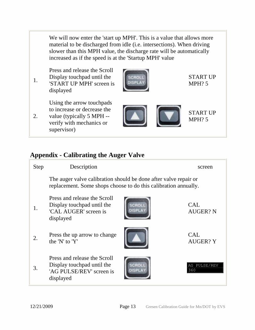
We will now enter the 'start up MPH'. This is a value that allows more
material to be discharged from idle (i.e. intersections). When driving
slower than this MPH value, the discharge rate will be automatically
increased as if the speed is at the 'Startup MPH' value
1.
Press and release the Scroll
Display touchpad until the
'START UP MPH' screen is
displayed
START UP
MPH? 5
2.
Using the arrow touchpads
to increase or decrease the
value (typically 5 MPH --
verify with mechanics or
supervisor)
START UP
MPH? 5
Appendix - Calibrating the Auger Valve
Step Description screen
The auger valve calibration should be done after valve repair or
replacement. Some shops choose to do this calibration annually.
1.
Press and release the Scroll
Display touchpad until the
'CAL AUGER' screen is
displayed
CAL
AUGER? N
2. Press the up arrow to change
the 'N' to 'Y'
CAL
AUGER? Y
3.
Press and release the Scroll
Display touchpad until the
'AG PULSE/REV' screen is
displayed
AG PULSE/REV
360
12/21/2009 Page 14 Gresen Calibration Guide for Mn/DOT by EVS
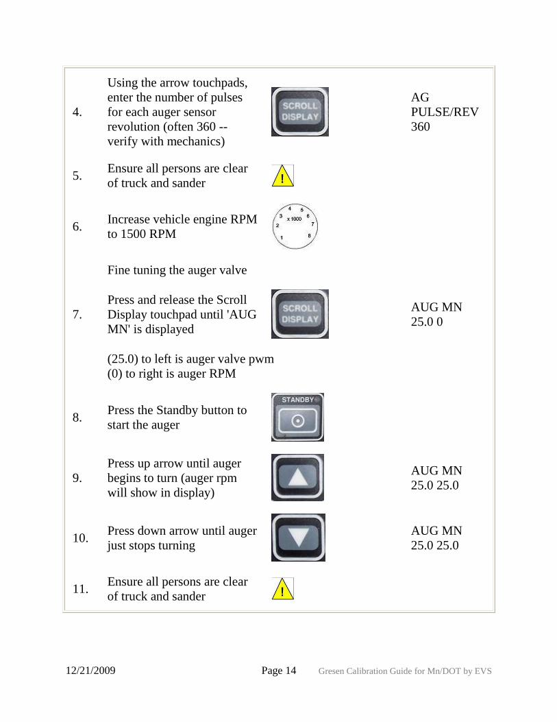
4.
Using the arrow touchpads,
enter the number of pulses
for each auger sensor
revolution (often 360 --
verify with mechanics)
AG
PULSE/REV
360
5. Ensure all persons are clear
of truck and sander
6. Increase vehicle engine RPM
to 1500 RPM
Fine tuning the auger valve
7.
Press and release the Scroll
Display touchpad until 'AUG
MN' is displayed
AUG MN
25.0 0
(25.0) to left is auger valve pwm
(0) to right is auger RPM
8. Press the Standby button to
start the auger
9.
Press up arrow until auger
begins to turn (auger rpm
will show in display)
AUG MN
25.0 25.0
10. Press down arrow until auger
just stops turning
AUG MN
25.0 25.0
11. Ensure all persons are clear
of truck and sander
12/21/2009 Page 15 Gresen Calibration Guide for Mn/DOT by EVS
12.
Press and release the Scroll
Display touchpad until the
'AUG MAX' screen is
displayed
AUG MAX
60.0 0
(60.0) to left is auger valve pwm, (0) to right is auger RPM
13. Press the Standby button to
start the auger
The auger should be rotating at high speed
14.
Using the up and down
buttons adjust the auger
speed just to the point where
it no longer increases the
displayed RPM
AUG MAX
60.0 ?
15. Write down this number
16.
Press and release the Scroll
Display touchpad until the
'MAX AG RPM' screen is
displayed
MAX AG
RPM 0
17.
Using the up and down
buttons, enter the 'AUG
MAX' just recorded
MAX AG RPM 0
Appendix - Calibrating the Spinner Valve
Step Description screen
The spinner valve calibration does [not] need to be done annually. It
should be done when there is a problem.
12/21/2009 Page 16 Gresen Calibration Guide for Mn/DOT by EVS
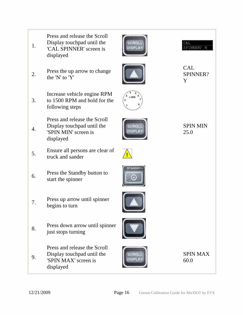
1.
Press and release the Scroll
Display touchpad until the
'CAL SPINNER' screen is
displayed
CAL
SPINNER? N
2. Press the up arrow to change
the 'N' to 'Y'
CAL
SPINNER?
Y
3.
Increase vehicle engine RPM
to 1500 RPM and hold for the
following steps
4.
Press and release the Scroll
Display touchpad until the
'SPIN MIN' screen is
displayed
SPIN MIN
25.0
5. Ensure all persons are clear of
truck and sander
6. Press the Standby button to
start the spinner
7. Press up arrow until spinner
begins to turn
8. Press down arrow until spinner
just stops turning
9.
Press and release the Scroll
Display touchpad until the
'SPIN MAX' screen is
displayed
SPIN MAX
60.0
12/21/2009 Page 17 Gresen Calibration Guide for Mn/DOT by EVS
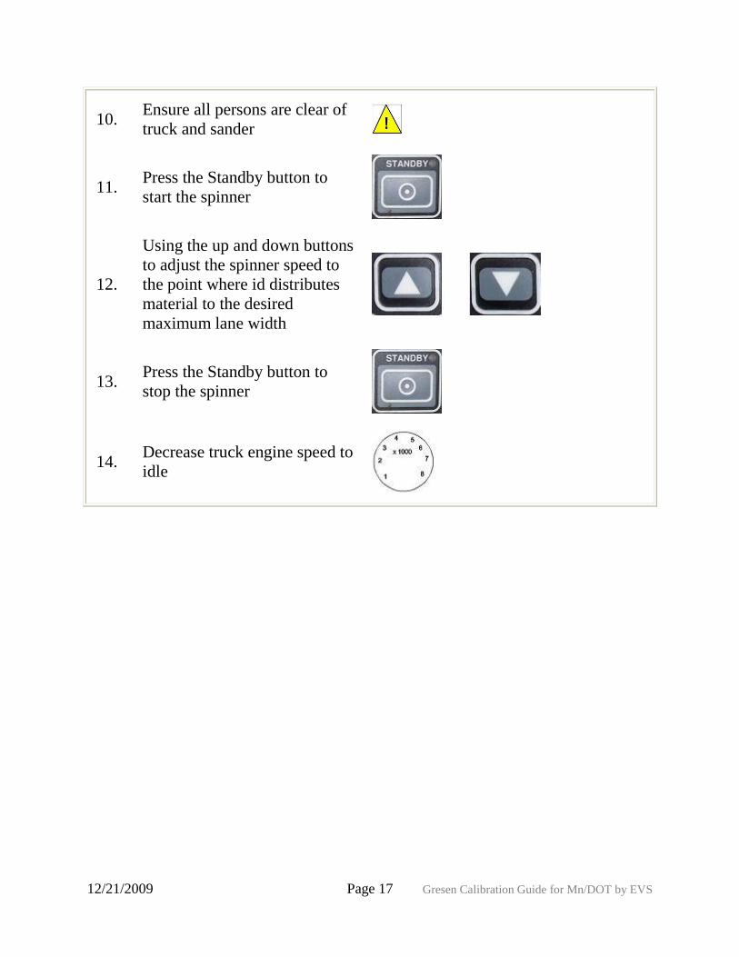
10. Ensure all persons are clear of
truck and sander
11. Press the Standby button to
start the spinner
12.
Using the up and down buttons
to adjust the spinner speed to
the point where id distributes
material to the desired
maximum lane width
13. Press the Standby button to
stop the spinner
14. Decrease truck engine speed to
idle


![OPES Web Portal: Conference... · Microsoft PowerPoint - Gresen Presentation--VA Psychology Leadership 2011 final Part 3 [Compatibility Mode] Author: Owner Created Date: 5/11/2011](https://static.fdocuments.in/doc/165x107/5f697ed870ab93534d7fe5b6/opes-web-portal-conference-microsoft-powerpoint-gresen-presentation-va.jpg)