
Greenflex_ETA_process_0716
29
Presentation for ETA process
-
Upload
giulio-zanelli -
Category
Documents
-
view
93 -
download
0
Transcript of Greenflex_ETA_process_0716

Presentation for ETA process

2
Presentation for ETA process
SUMMARY1. What is ? 32. How is produced? 33. Dimension of 34. Typical Physical and mechanical properties of 45. How is used in production and how does it work? 46. Typical position of inside a panel 57. Example of actions on the inside a panel 68. Tensional / failure criterion approach: the Tsai-Wu criterion 99. Reduction coefficient for compression characteristic resistance used in the Tsai-Wu tensional criterion 1110. Definition of the minimal Factor Of Safety (FOS) for the application ( connectors) with the tensional Tsai Wu tensional criterion 1511. Semi probabilistic state limit method 1912. DURABILITY tests applicable to connectors 2413. connectors used in Fire-resistance-rated Construction 2514. connectors used in condition with very low temperature 2615. Action due to the earthquake 2616. Conclusions 27

3
Presentation for ETA process
1. What is ?
2. How is produced?
3. Dimension of
is an innovative connection system for precast insulated sandwich panels made of a thermosetting vinyl resin reinforced with different types of glass fibers.
is an internationally patented product that is part of construction system.
There are three section dimension of the element reported in the following drawing.
The length of the pieces is designed according with specific application of the .
is “pull through” in a production line that produce long bars of Glass Fiber Reinforce Polymer (GFRP) using multi axial reinforced made in special glass fibers. Those bars, after the production, are cut in the pieces that are the .The vinyl ester resin is specifically formulated to efficiently withstand the action of concrete-borne alkali.
Production line
Multi axial Reinforcements

4
Presentation for ETA process
4. Typical Physical and mechanical properties of
5. How is used in production and how does it work?
has to be fixed to the welded wire mesh of the first concrete layer in a very simple way.
It provides a maximum flexibility in optimizing industrial cycles and subsequent operations needed to make the panel.
can be used for any type of precast sandwich panel: insulated, lightweight and fire resistant applica-tion, horizontal or vertical panels with and without door/window openings and entrance doors.
allows no heat transfer between the two concrete layers thanks to its very low thermal conductivity.
For this reason, in accordance with the EN ISO Standards 6946 Appendix D2, “NO CORRECTIONS ARE REQUIRED” in the calculation of thermal transmittance of insulated panels. With , the stress caused by the weight of the concrete layers is transferred to the entire panel structu-re, dramatically reducing local stress on the structural parts of the panel and hence its overall size.
The deformations resulting from thermal expansion are balanced by ’s flexibility.
GREEnFLEx PHYSICAL/MECHAnICAL PROPERTIES
REFEREnCE STAnDARDS VALUE UnIT OF MEASUREMEnT
Specific weight ASTM D792 or ISO 1183 1.70 ± 0.10 g/cm3
Glass content in weight ISO 1172 57 ± 5 %
Tensile strength (along the direction of the fibers) See conclusions 450 ± 30 MPa
Tensile strength (in the direction transverse to the fiber) See conclusions 120 ± 10 MPa
Compression strength (along the direction of the fibers) See conclusions 300 ± 20 MPa
Compression strength (in the direction transverse to the fiber) See conclusions 100 ± 10 MPa
Shear strength See conclusions 100 ± 10 MPa
Linear thermal expansion coefficient ASTM D696 or ISO 11359-2 < 13x10-6 k-1
Thermal conductivity EN 12667 < 0,235 W/mK
Melting temperature DSC ISO 11357 Doesn’t melt -
Flammability class UL 94 HB Class

5
Presentation for ETA process
6. Typical position of inside a panelThe typical layout of is shown below for “horizontal” and “vertical” panels.
For each of the elements placed into the panels, should be determinate the actions N (axial), T (shear) and M (moment) under the following conditions and combination of those:
• Dead weight of the external layer• Concrete shrinkage• Thermal deformation (winter and summer condition)• Wind pressure• Earthquake • Fire
In the following paragraph is shown an example of calculation of the actions on the pieces.Even if theoretically the case is a three dimensional case (3D) the results of the example can easily show that the action out of the plane of the pieces are at least 10000 lower than the action in the plane. This is due to the specific shape of the pieces.For this reason the case has to be considered as a bi dimensional case (2D).

6
Presentation for ETA process
7. Typical Physical and mechanical properties of The typical layout of is shown below for “horizontal” and “vertical” panels.
Every pieces is numbered. To study the behavior of the panel subject to external actions and the differential shrinkage between different layers was carried out a calculation with finite element model. The internal structural layer of the panel has been bounded superiorly to the translation in X and Y, the bottom was placed a support constraint (constraint to the translation in X, Y, Z).

7
Presentation for ETA process
The following pictures are explanatory of the calculation model.
The numeric simulation has been carried on considering different combinations of the loads.
One of the worst condition is the combination is: dead weight, low external temperature (winter condition), shrinkage of concrete and negative pressure of the wind.
The software used, “ SAP2000 rel. 15.0.1 “ (Computers and Structures inc. ,1995 University Avenue, Berkeley , CA 94704) give as output the following table.
Internal structural layer
Position of the connectors
External layer

8
Presentation for ETA process
Actions on the connectors
Consider that: - P, the axial force: it is in the plane of the connector - V2, the shear force in the 1-2 plane: it is in the plane of the connector - V3, the shear force in the 1-3 plane: it is out the plane of the connector and the value is approximately null - T, the axial torque (about the 1-axis): it is out the plane of the connector and the value is null - M2, the bending moment in the 1-3 plane (about the 2-axis) : it is out the plane of the connector and the value is approximately null - M3, the bending moment in the 1-2 plane (about the 3-axis): it is in the plane of the connector
Considering the result the case has to be considered as a bi dimensional case (2D) and not a three dimensional one (3D).Once it is known the value of P, V2 and M3 it is possible to calculate the value of the action per surface unit (s1, s2, t12y=t21).
Axis 2Axis 1
Axis 3
TABLE: Element Forces - FramesFrame Station OutputCase CaseType P V2 V3 T M2 M3 n° S11 S12 S13 SidText mm Text Text N N N N-mm N-mm N-mm flexò N/mm2 N/mm2 N/mm2 N/mm2392 185 COMB4-INVERNALE-VENTO Combination 1360 -1149 -1 0 39 95479 1 55.1 9.8 0.0 57.7393 185 COMB4-INVERNALE-VENTO Combination 2253 -1162 0 0 20 98092 2 61.2 10.0 0.0 63.6394 185 COMB4-INVERNALE-VENTO Combination 2612 -1152 0 0 0 97558 3 62.7 9.9 0.0 65.0395 185 COMB4-INVERNALE-VENTO Combination 2361 -1181 0 0 -20 99724 4 62.6 10.1 0.0 65.0396 185 COMB4-INVERNALE-VENTO Combination 1062 -1189 1 0 -48 98550 5 55.0 10.2 0.0 57.8397 185 COMB4-INVERNALE-VENTO Combination -121 -1516 -1 0 36 117921 6 58.9 13.0 0.0 63.1398 185 COMB4-INVERNALE-VENTO Combination -450 -1533 0 0 25 119374 7 61.4 13.1 0.0 65.5399 185 COMB4-INVERNALE-VENTO Combination 214 -1540 0 0 2 119792 8 59.9 13.2 0.0 64.1400 185 COMB4-INVERNALE-VENTO Combination -150 -1560 0 0 -21 121417 9 60.6 13.4 0.0 64.9401 185 COMB4-INVERNALE-VENTO Combination -505 -1568 1 0 -40 121943 10 63.2 13.4 0.0 67.3402 185 COMB4-INVERNALE-VENTO Combination 1908 -1877 -1 0 36 139237 11 79.6 16.1 0.0 84.3403 185 COMB4-INVERNALE-VENTO Combination 2715 -1882 0 0 29 138432 12 83.7 16.1 0.0 88.3404 185 COMB4-INVERNALE-VENTO Combination 2975 -1902 0 0 6 139780 13 85.5 16.3 0.0 90.1405 185 COMB4-INVERNALE-VENTO Combination 2917 -1916 0 0 -17 140905 14 85.9 16.4 0.0 90.5406 185 COMB4-INVERNALE-VENTO Combination 1628 -1943 0 0 -37 144352 15 80.5 16.7 0.0 85.5

9
Presentation for ETA process
8. Tensional / failure criterion approach: the Tsai-Wu criterionTo verify the connectors the designer can decide to use a tensional / failure criterion or a semi probabilistic state limit method. In the first case, as the classic Von Mises tensional / failure criterion is adapted only for isotropic materials, for GFRC is better to adopt the Tsai-Wu failure criterion as this criterion is used to determine the safety factor for orthotropic composite shell. This criterion considers the total strain energy (the energy of distortion and energy of expansion) to precede the failure. It distinguishes between the forces of compression and tension failure.
For a 2D stress state (s3 = 0, t13 = 0, t23 = 0) as our case, the failure criterion of Tsai-Wu is expressed as follows:
The coefficients Fij of orthotropic failure criterion of Tsai-Wu parameters are related to the strength of the material of the plate and are determined experimentally. Can be calculated using the following formulas:
Where:X1
T = maximum characteristic tension force along the direction of the fiberX1
C = maximum characteristic compression force along the direction of the fiberX2
T = maximum characteristic tension force in the direction transverse to the fiberX2
C = maximum characteristic compression force in the direction transverse to the fiberX12
T = X12C = maximum characteristic resistance positive cutting
Classic Von Mises and Tresca tensional / failure criterion vs Tsai Wu tensional / failure criterion
Tsai Wu

10
Presentation for ETA process
Once the state of stress of the piece is known (s1, s2, t12) the with the Tsai Wu criterion we can obtain the Factor Of Safety (FOS). This is the coefficient all the components of the stress of the laminate must be multiplied to reach the point of failure of the laminate, according to the criterion of Tsai-Wu above. The coefficient FOS for the failure of the laminate can be calculated as follows:
A safety factor greater than 1.0 theatrically indicates that the laminate is not at risk of failure.The failure occurs when FOS ≥ 1.It is important to understand that the Tsai-Wu failure criterion cannot predict different failure modes, including failu-re of the fibers, the matrix, the fiber-matrix interface failure and the buckling of the compressed side of the piece.For this reason this criteria should be trimmed with a specific reduction coefficient evaluated with experimental tests (please see § 9).What it is important to highline here is that to characterize the behavior of such a pieces it is mandatory to consider as first the values of:
X1T = maximum characteristic tension force along the direction of the fiber
X1C = maximum characteristic compression force along the direction of the fiber
X2T = maximum characteristic tension force in the direction transverse to the fiber
X2C = maximum characteristic compression force in the direction transverse to the fiber
X12T = X12
C = maximum characteristic resistance positive cutting
The number of specimens should be evaluated. Referring to the ACCEPTANCE CRITERIA FOR FIBER-REINFORCED COMPOSITE CONNECTORS ANCHORED IN CONCRETE (AC320) that is the most worldwide applicable document to this kind of connector, we should consider 20 specimens for each value as stated in table 1.

11
Presentation for ETA process
As mentioned above, the Tsai-Wu failure criterion cannot predict different failure modes, including failure of the fibers, the matrix, the fiber-matrix interface failure and the buckling of the compressed side of the piece.The usual state of stress in elements like is given by a combination of axial tension (or compression), moment and shear and the failure of the pieces occurs for buckling of the compressed side of the piece as well shown in the broken the specimens testes in the laboratory, with a the fiber-matrix interface failure.
The typical graph reporting the deformation of the piece under shear test of a true piece is the following.
The difference between the Tsai-Wu prediction and the actual results (given by the buckling of the compressed side of the specimen) can be taken in account applying a reduction coefficient to the maximum compression characteristic force of the laminate material along the direction of the fiber and in the direction transverse to the fiber. The reduction coefficient (w) is correct when the Tsai-Wu model predict with a Factor Of Safety equal to 1.0 the failure of the specimen.
9. Reduction coefficient for compression characteristic resistance used in the Tsai-Wu tensional criterion
Tsai – Wu prediction Actual Test Curve
Tsai – Wu prediction with a reduction coefficient for max compression force

12
Presentation for ETA process
Example of correction with the reduction coefficient (w).Let’s consider a specimen under test with the material characteristics reported in the table below.This specimen has a rectangular section (thickness 4 mm, width 85 mm) and a length of 100 mm.We can divide the section of element with a mesh of 17 shells alias 18 nodes (see the picture below).
Once P is given (n the example the failure in laboratory of the tested specimen occurs at a shear force of P = 13000 N), we can calulate the state of stress in all the nodes of the section for example with a Finite Elements Method (FEM) solutor and obtaion the s1, s2, t12 (MPa) of all the nodes of the section and consequently the values (node by node) of C1, C2 and R (Tsai-Wu model coefficients).

13
Presentation for ETA process
If we do not reduce the compression maximum characteristics of the material with a reduction coeffiecient w = 1.340 that takes in occunt the buckling of the piece (see graph of the test report), the Tsai Wu model returns a FOS higher than 1. If we reduce the compression maximum characteristics with a reduction coeffiecient w = 1.340 the Tsai Wu model returns a FOS ≥ 1 in all the 18 nodes of the section.
MATERIAL CHARACTERISTICS CHARACTERISTIC LABORATORY
xiC Reduced
by w = 1.340 ACTIOnSPECIMEn RUPTURE
VALUE FOS = 1
Max. Tension longitudinal X1T 400 400 Mpa P = shear force 13000 N
Max. Compression longitudinal X1
C 290 216 Mpa V2 = axial force 0
Max. Tension transversal X2T 80 80 Mpa Lenght (mm) 100
Max. Compression transversal X2
C 135 101 Mpa Width (mm) 85
Max positive cutting X12T = X12
C 95 95 Mpa Section mm2 340
F11 F22 F12 F66 F1 F21.155E-05 1.241E-04 -1.893E-05 1.119E-04 -2.121E-03 2.574E-03
nodes of section
Action on the nodes of the section Tsai-Wu model coefficients Fatt. Sicur. (FOS)min= 1C1 C2 Rs1 s2 t12
1 228.94 49.47 -37.19 0.635 -0.358 1.634 1.572 134.33 37.92 -37.92 0.355 -0.187 1.206 1.963 96.78 30.51 -38.64 0.279 -0.127 1.064 2.134 71.50 24.95 -38.28 0.233 -0.087 0.969 2.275 53.08 20.55 -38.28 0.208 -0.060 0.913 2.346 38.28 16.14 -38.28 0.190 -0.040 0.872 2.407 25.86 11.63 -38.28 0.177 -0.025 0.842 2.458 14.95 7.04 -38.28 0.169 -0.014 0.821 2.489 4.91 2.35 -38.28 0.164 -0.004 0.811 2.4810 -4.91 -2.35 -38.28 0.164 0.004 0.811 2.4511 -14.95 -7.04 -38.28 0.169 0.014 0.821 2.4012 -25.86 -11.63 -38.28 0.177 0.025 0.842 2.3113 -38.28 -16.14 -38.28 0.190 0.040 0.872 2.1914 -53.08 -20.55 -38.28 0.208 0.060 0.913 2.0615 -71.50 -24.95 -38.28 0.233 0.087 0.969 1.8916 -96.78 -30.51 -38.64 0.279 0.127 1.064 1.6817 -134.33 -37.92 -37.92 0.355 0.187 1.206 1.4418 -228.94 -49.47 -37.19 0.635 0.358 1.634 1.00

14
Presentation for ETA process
In the case shown above the failure occurs in the node 18 where we have the maximum compression s1 as it can be easily verified both on the table and on the picture of the stress levels.
The conclusion is that is not only important to define trough laboratory tests the characteristics of the material (X1T, X1
C, X2
T, X2C, X12
T=X12C) but it is also important to define a range of use of connector ( ) and find for the
minimal, maximal and average thickness insulation (length of the connector) the w reduction coefficient of the maximum compression characteristic force of the laminate material along the direction of the fiber and in the direction transverse tothe fiber.
A polynomial (parabolic) interpolation between those value of w reduction coefficient could be considered acceptable.
note regarding the calculation of the state of stress in all the nodes of the section for example with a Finite Elements Methos solutor.
To obtain the state of stress with a Fsolutor is necessary to know modulus of elasticity of the different charactrestic of the material.
E1T = longitudinal tensile modulus of elasticity
E2T = transverse tensile modulus of elasticity
E1C = modulus of longitudinal elasticity in compression
E2C = modulus of transverse elasticity in compression
E12C = E12
T = shear elasticity modulus
nodes of section
Action on the nodes of the section Tsai-Wu model coefficients Fatt. Sicur. (FOS)min= 1C1 C2 Rs1 s2 t12
18 -228.94 -49.47 -37.19 0.635 0.358 1.634 1.00

15
Presentation for ETA process
To determine the value to be considered acceptable factor of safety we can refer to existing standards that relate Glass Fiber Reinforced Composite.
There are some application areas highly regulated as containers of chemicals, liquids or gases, or tanks of the road.
The principle is similar for all the standards, with some variations: use a formula of multiplication factors, all greater than or equal to 1.
The EN13-121 - “ Tanks and containers made of plastic reinforced with fiberglass “ which is one of the few existing rules and the formula for the calculation of the Factor Of Safety, propose the following formula.
K = FOS (Factor Of Safety) ≥ 2 x A1 x A2 x A3 x A4 x A5
Where Ai are 5 different factors corresponding to different types of stress or risks associated with the application. In this case those factors could be summarized as follows:
A1: Constance of product quality. The elements are made from pull-trough profiles in a continuous process, and therefore well controllable. So A1=1.
A2: The factor “chemical” is limited (this type of resin reinforced resin is resistant to the alkaline environment of concrete and used for a variety of applications for many years). So, again, A2 =1.
A3: The temperature setting is not critical (excluding the case of fire resistant panels).In normal condition the connector remains in temperatures below 23±2 ° C .For fiber reinforced vinyl ester resin the temperature of HDT (Heat Deflection Temperatures) is over 100 °C.The Heat Deflection Temperatures is the temperature at which to test bar, loaded to the specified bending stress, deflects by 0.010 inch (0.25mm).The formula proposed by EN13-121 is:
A3 = 1,0 + 0,4 x (T – 20) / (HDT- 40) that for our case means:
A3=1.033
A4: a coefficient for fatigue cycles. But if the design of the structure is consistent with what the material is no greater than 0.2% (other regulatory requirements of these standards) deformation can take A4 = 1.0. This criterion of 0.2% is related to the maximum deformation of the material beyond which micro cracks could start to appear related delamination of the resin from the fiber. This value corresponds to about 10% of the ultimate tensile deformation of the resin which rotates generally around 2%.
10. Definition of the minimal Factor Of Safety (FOS) for the application ( connectors) with the tensional Tsai Wu tensional criterion.

16
Presentation for ETA process
In any case should be verified the behavior of the material after a certain number of cycles.
The cycles are basically due to the thermic variation of the temperature of the external layer of the precast panel.
Considering the real state of stress inside the pieces and the number of cycles during 50 years of life of the panel, should be performed a cyclic test under load control at a frequency of 2 Hz, imposing a sinusoidal cycle between a σmin = σmax = 40 MPa and 80 MPa (see Figure), for 30000 cycles.
A5: The parameter “ time” that for long term means “expected life of the building “ is the most important factorto consider.
The Table A5 of the norm EN13-121 for an expected life time of 50 years, reports the value of A5=1.9 for elements produced with continues fibers (such the case of pull – trough profiles) for poly ester resin reinforced with glass fibers.The same table, for 30 minutes report the value of A5=1 that could be applied in case of earthquake and the value of A5=1.5 for 10 years of life time. It is reasonable consider and intermediate value of 1.2 for 4 hours that can be the case of fire condition.
frequency
time number of cycles
Chart5 -ValueofthepartialcalculationcoefficientA5

17
Presentation for ETA process
So applying the formula:
FOS (Factor Of Safety) ≥ 2 x A1 x A2 x A3 x A4 x A5 = 2 x 1 x 1 x 1.034 x A5
FOS ≥ 2 x 1.034 x 1.9 =~ 4 for life time of 50 yearsFOS ≥ 2 x 1.034 =~ 2 for earthquake (30 minutes)FOS ≥ 2 x 1.034 x 1.2 =~ 2.5 for fire condition (4 hours)
Those Factor Of Safety values, calculated according to an existing standard for application different (Tanks and containers made of plastic reinforced with fiberglass) than the Green Flex connector are in any case compatible with the classic coefficient values used in field of construction.
It is important to underline that using this Factor Of Safety values the deformation of the pieces tested with a classic shear test largely remain under the elastic limit.
Graph reporting the deformation of the piece under shear test of a true piece with the limitation given by the Factor Of Safety = 4.
Tsai – Wu prediction Actual Test Curve
Tsai – Wu prediction with a reduction coefficient for max compression force
Limit using a Factor Of Safety = 4The curve remains in elastic field

18
Presentation for ETA process
In the example of § 9 with a specimen with a rectangular section (thickness 4 mm, width 85 mm) and a length of 100 mm, if we want to obtain a Factor Of Safety FOS = 4, we must reduce the load of 4 times: 13000 N / 4 = 3250 N
MATERIAL CHARACTERISTICS CHARACTERISTIC LABORATORY
xiC Reduced
by w = 1.340 ACTIOnLIFE TIME
50 YEARS => FOS = 4
Max. Tension longitudinal X1T 400 400 Mpa P = shear force 3250 N
Max. Compression longitudinal X1
C 290 216 Mpa V2 = axial force 0
Max. Tension transversal X2T 80 80 Mpa Lenght (mm) 100
Max. Compression transversal X2
C 135 101 Mpa Width (mm) 85
Max positive cutting X12T = X12
C 95 95 Mpa Section mm2 340
F11 F22 F12 F66 F1 F21.155E-05 1.241E-04 -1.893E-05 1.119E-04 -2.121E-03 2.574E-03
nodes of section
Action on the nodes of the section Tsai-Wu model coefficients Fatt. Sicur. (FOS)
min= 4.02C1 C2 Rs1 s2 t12
1 57.24 12.37 -9.30 0.040 -0.090 0.408 6.272 33.58 9.48 -9.48 0.022 -0.047 0.301 7.853 24.19 7.63 -9.66 0.017 -0.032 0.266 8.544 17.88 6.24 -9.57 0.015 -0.022 0.242 9.085 13.27 5.14 -9.57 0.013 -0.015 0.228 9.376 9.57 4.04 -9.57 0.012 -0.010 0.218 9.617 6.46 2.91 -9.57 0.011 -0.006 0.210 9.798 3.74 1.76 -9.57 0.011 -0.003 0.205 9.909 4.91 0.59 -9.57 0.010 -0.001 0.203 9.9210 -1.23 -0.59 -9.57 0.010 0.001 0.203 9.8111 -3.74 -1.76 -9.57 0.011 0.003 0.205 9.5812 -6.46 -2.91 -9.57 0.011 0.006 0.210 9.2313 -9.57 -4.04 -9.57 0.012 0.010 0.218 8.7714 -13.27 -5.14 -9.57 0.013 0.015 0.228 8.2215 -17.88 -6.24 -9.57 0.015 0.022 0.242 7.5816 -24.19 -7.63 -9.66 0.017 0.032 0.266 6.7217 -33.58 -9.48 -9.48 0.022 0.047 0.301 5.7418 -57.24 -12.37 -9.30 0.040 0.090 0.408 4.02

19
Presentation for ETA process
11. Semi probabilistic state limit method.
As in Europe and in Italy during the last 20 years the use of Glass Fiber Reinforced Polymers structural elements has become more and more important, during the period 2002-2007 the Italian “Consiglio Nazionale delle Ricerche” – CNR (Italian national research institute) has issued several Technical documentation relating to the use of this material in construction.The CNR-DT 205/2014 (Istruzioni per la progettazione, l’esecuzione ed il Controllo delle strutture realizzate con profili pultrusi si material composito fibrorinforzato (FRP)” introduces a semi probabilistic state limit approach for this kind of material consistencly with the Euro Codes.The verification of the elements (connectors) must be carried out both in respect of limit states (SLS) vis both the ultimate limit state (ULS), as defined in Euro Codes.
The designer must verify, by the partial factor method, that in all design situations is not violated any state limit, adopting the calculation values of actions and resistances. Therefore it is necessary to satisfy the following restriction:
Ad ≤ Rd
where Ad is the design Action and Rd is the design Resistance capacity.
The Ad are given by the Euro Codes reference to the life of the structure and is a function of the stresses inside the connector.
Ad = fAd (sd,i ) where sd,I are the different stresses inside the pieces
The design resistance capacity Rd is expressed as follows:
Rd = 1/ γ Rd • fRd (xd,i) where xd,i are the generic properties of resistance or deformation of a material and can be expressed, in general form, by means of a following relation:
xd,i = η • xk,i / γ m xd,i = ηe • ηl • xk,i / γ m1 • γ m2 where:
xk,i = characteristic value of the ith resistance (with fractile less than 5%)
ηe = environmental conversion factor due to the alkaline ambience of the concrete. As the polyester resin protect the
fiber, this factor con be considered ηe = 1 (it is similar to the A2 “chemical” of the EN13-121 see § 10.)
ηl = conversion factor for long-term action (as the ones on the GreenFlex connectors)The value is given by the table 3-3 of the CNR-DT 205/2014 for quasi permanent loads such as weight of the external layer and concrete shrinkage.

20
Presentation for ETA process
So for SLS => ηl = 0,30 and for USL => ηl = 1,00
This value has the same meaning of the A5 (“ time” that for long term means “expected life of the building “) of the of the EN13-121 see § 10.γ m1 = this partial coefficient of the material takes into account the level of uncertainty in the determination of the properties of the material. The table -1 of the CNR-DT 205/2014 suggests the value of γm1 = 1,15 for GFRP as the is an hi variation of the laboratory results.γm2 = this partial coefficient of the material should be considered γ m2 = 1 for SLS and γ m2 = 2 for USL due to the due to the fragility of the material at final break
Considering all above, the from the formula xd,i = ηe • ηl • xk,i / γ m1 • γ m2 we obtain:
xd,i = 0,26 • xk,i = 1 • xk,i for SLS 4xd,i = 0,43 • xk,i = 1 • xk,i for ULS 2,3γ Rd = is a partial factor that takes into account uncertainties inherent in the resistance model (Rd = 1/ γ Rd • fRd (xd,i ) ) or in the experimental procedure.In our specific case uncertainties inherent in the resistance model are due to the fact that the GreenFlex connector under test has a buckling behavior that depends on the free length of the piece (thickness of the insulation of the panel). As much long it is, as higher is the effect of the buckling.Again (similarly to the w coefficient of § 9) it is important to define a range of use of connector (GreenFlex) and find for the minimal, maximal and average thickness insulation (length of the connector) the γ Rd a partial factor.A polynomial (parabolic) interpolation between those value of w reduction coefficient could be considered acceptable.
Coming back to the formula:
Ad ≤ Rd => Rd / Ad ≥ 1
as
Rd = 1/ γ Rd • fRd (xd,i ) and Ad = fAd (sd,i )

21
Presentation for ETA process
We obtain that:
1 / γ Rd • fRd (xd,i) / fAd (sd,i) ≥ 1
In this formula we find a more generic formulation of the FOS (see Tsai-Wu model)
FOS => fRd (xd,i) / fAd (sd,i)And γ Rd has the same meaning of w with the difference that w reduce only the compression resistance of the material while the γ Rd reduce the global function of the resistance fRd (xd,i) .
Finally looking at the formulas:
xd,i = 0,26 • xk,i = 1 • xk,i for SLS 4 andxd,i = 0,43 • xk,i = 1 • xk,i for ULS 2,3We notice that the reduction of 4 for the Xk,I at the SLS is equivalent to assume
FOS ≥ 2 x 1.034 x 1.9 =~ 4 for life time of 50 years (see conclusion of § 11)
That is the same of reducing by 4 the loads (see § 10 page 18).
In the same way the reduction of 2,3 for the xk,I 1 ( w vs γ Rd ).

22
Presentation for ETA process
Hereby we propose again the example of § 9 for the rupture case (specimens tested in the laboratory) with the use of γRd applied to the FOS and that in this case is γRd = 1,36.
MATERIAL CHARACTERISTICS CHARACTERISTIC LABORATORY
xiC Reduced
by w = 1.340 ACTIOnSPECIMEn RUPTURE
FOS = 1 x 1,36
Max. Tension longitudinal X1T 400 400 Mpa P = shear force 13000 N
Max. Compression longitudinal X1
C 290 216 Mpa V2 = axial force 0
Max. Tension transversal X2T 80 80 Mpa Lenght (mm) 100
Max. Compression transversal X2
C 135 101 Mpa Width (mm) 85
Max positive cutting X12T = X12
C 95 95 Mpa Section mm2 340
F11 F22 F12 F66 F1 F21.155E-05 1.241E-04 -1.893E-05 1.119E-04 -2.121E-03 2.574E-03
odes of section
Action on the nodes of the section Tsai-Wu model coefficients FOS
FOS / γ Rd
( γRd = 1 x 1,36)C1 C2 Rs1 s2 t12
1 228.94 49.47 -37.19 0.513 0.035 1.634 1.57 1.002 134.33 37.92 -37.92 0.306 0.066 1.206 1.96 1.253 96.78 30.51 -38.64 0.251 0.064 1.064 2.13 1.384 71.50 24.95 -38.28 0.215 0.059 0.969 2.27 1.495 53.08 20.55 -38.28 0.196 0.054 0.913 2.34 1.566 38.28 16.14 -38.28 0.183 0.046 0.872 2.40 1.637 25.86 11.63 -38.28 0.174 0.035 0.842 2.45 1.698 14.95 7.04 -38.28 0.167 0.022 0.821 2.48 1.759 4.91 2.35 -38.28 0.164 0.007 0.811 2.48 1.8010 -4.91 -2.35 -38.28 0.164 -0.007 0.811 2.45 1.8311 -14.95 -7.04 -38.28 0.167 -0.022 0.821 2.40 1.8512 -25.86 -11.63 -38.28 0.174 -0.035 0.842 2.31 1.8413 -38.28 -16.14 -38.28 0.183 -0.046 0.872 2.19 1.8114 -53.08 -20.55 -38.28 0.196 -0.054 0.913 2.06 1.7615 -71.50 -24.95 -38.28 0.215 -0.059 0.969 1.89 1.6916 -96.78 -30.51 -38.64 0.251 -0.064 1.064 1.68 1.5717 -134.33 -37.92 -37.92 0.306 -0.066 1.206 1.44 1.4118 -228.94 -49.47 -37.19 0.513 -0.035 1.634 1.00 1.05

23
Presentation for ETA process
Hereby we propose again the example of § 9 for the service load = rupture load / 4 with the use of γRd applied to the FOS and that in this case is γRd = 1,36 and the Mechanical characteristics reduce by 4.
MATERIAL CHARACTERISTICS CHARACTERISTIC LABORATORY
xiC Reduced
by w = 1.340 ACTIOnLIFE TIME 50
YEARS => SERVICE LOAD =
RUPTURE LOAD/4
Max. Tension longitudinal X1T 400 400 Mpa P = shear force 3250 N
Max. Compression longitudinal X1
C 290 216 Mpa V2 = axial force 0
Max. Tension transversal X2T 80 80 Mpa Lenght (mm) 100
Max. Compression transversal X2
C 135 101 Mpa Width (mm) 85
Max positive cutting X12T = X12
C 95 95 Mpa Section mm2 340
F11 F22 F12 F66 F1 F21.155E-05 1.241E-04 -1.893E-05 1.119E-04 -2.121E-03 2.574E-03
nodes of section
Action on the nodes of the section Tsai-Wu model coefficients FOS
FOS / γ Rd
( γRd = 1 x 1,36)C1 C2 Rs1 s2 t12
1 228.94 49.47 -37.19 0.513 0.035 1.634 1.57 1.002 134.33 37.92 -37.92 0.306 0.066 1.206 1.96 1.253 96.78 30.51 -38.64 0.251 0.064 1.064 2.13 1.384 71.50 24.95 -38.28 0.215 0.059 0.969 2.27 1.495 53.08 20.55 -38.28 0.196 0.054 0.913 2.34 1.566 38.28 16.14 -38.28 0.183 0.046 0.872 2.40 1.637 25.86 11.63 -38.28 0.174 0.035 0.842 2.45 1.698 14.95 7.04 -38.28 0.167 0.022 0.821 2.48 1.759 4.91 2.35 -38.28 0.164 0.007 0.811 2.48 1.8010 -4.91 -2.35 -38.28 0.164 -0.007 0.811 2.45 1.8311 -14.95 -7.04 -38.28 0.167 -0.022 0.821 2.40 1.8512 -25.86 -11.63 -38.28 0.174 -0.035 0.842 2.31 1.8413 -38.28 -16.14 -38.28 0.183 -0.046 0.872 2.19 1.8114 -53.08 -20.55 -38.28 0.196 -0.054 0.913 2.06 1.7615 -71.50 -24.95 -38.28 0.215 -0.059 0.969 1.89 1.6916 -96.78 -30.51 -38.64 0.251 -0.064 1.064 1.68 1.5717 -134.33 -37.92 -37.92 0.306 -0.066 1.206 1.44 1.4118 -228.94 -49.47 -37.19 0.513 -0.035 1.634 1.00 1.05

24
Presentation for ETA process
12. DURABILITY tests applicable to connectors.
The durability of the connectors is another parameter to be considered.Again the ACCEPTENCE CRITERIA FOR FIBER-REINFORCED COMPOSITE CONNECTORS ANCHORED IN CONCRETE (AC320) propose a set of test that can be adopted for our case and that is reported in the table 2 of the above mentioned criteria. Note: only for tensile strength.

25
Presentation for ETA process
13. connectors used in Fire-resistance-rated Construction.
The case of Fire-resistance-rated Construction should be considered evaluating the temperature of the connectors after specified time span such as 30’, 60’, 120’ and 240’.The diagrams of the temperature inside a concrete structure under fire condition depends on the time of the exposure to the fire, on the shape and dimensions of the concrete element, on the depth considered.The Fiber Reinforced connector with a Heat Deflection Temperatures (HDT) of about 100°C should not exposed at a temperature higher than 84±6 °C.The temperature in the position of the connector could be evaluated with specific software.In the following picture it is possible to find an example.
Brief description of the panel
Total thickness 33 cm.
17 cm structural layer (Including areas where there is 6 cm of internal concrete and 11 cm plystyrene lightening)10 cm of thermal insulation (polyurethane)6 cm of external concrete layerDimensions of the section considered 179.5 cm x 33 cm
The picture shows the output of a specific software with the temperature (°C) after 120’ and the temperature around the connectors is about 84°C. In the values of X1
T, X1C, X2
T, X2C, X12
T=X12C , should be determinate at this temperature, as well as the value of w (with a
true piece shear test) to be used in the Tsai-Wu model proposed in paragraph § 9. The FOS value to be used should be in this case FOS = 2.5.
Connector
Side exposed to the fire

26
Presentation for ETA process
14. connectors used in condition with very low temperature.
15. Action due to the earthquake.
The GreenFlex connectors are used for insulated concrete panel. In some markets the temperature can be very low. Even if the connector is protected by the insulation and even if the fiber reinforced vinyl ester resin typically do not suffer for low temperature at least some tension and compression tests carried at low temperature (-20°C) to have comparative results with standard temperature (23±2°C)
In the case of earth quake the sismic action should be taken in account increasing the weight of the 30% for vertical oscillation and give an action of the 50% of the weight for horizontal oscillation.As the Factor Of Safety in case of earthquake (30 minutes) is FOS = 2, for the most of the connectors (placed horizontal and vertical panel), when a connector is verified for normal condition is verified also in seismic condition.In same case, for horizontal panels, as there are not connectors oriented to carry horizontal action, it is simply necessary to added same connector in the middle of the panel.
Additional pieces for seismic action equal to 50% of the weight of the external layer.
27
Presentation for ETA process
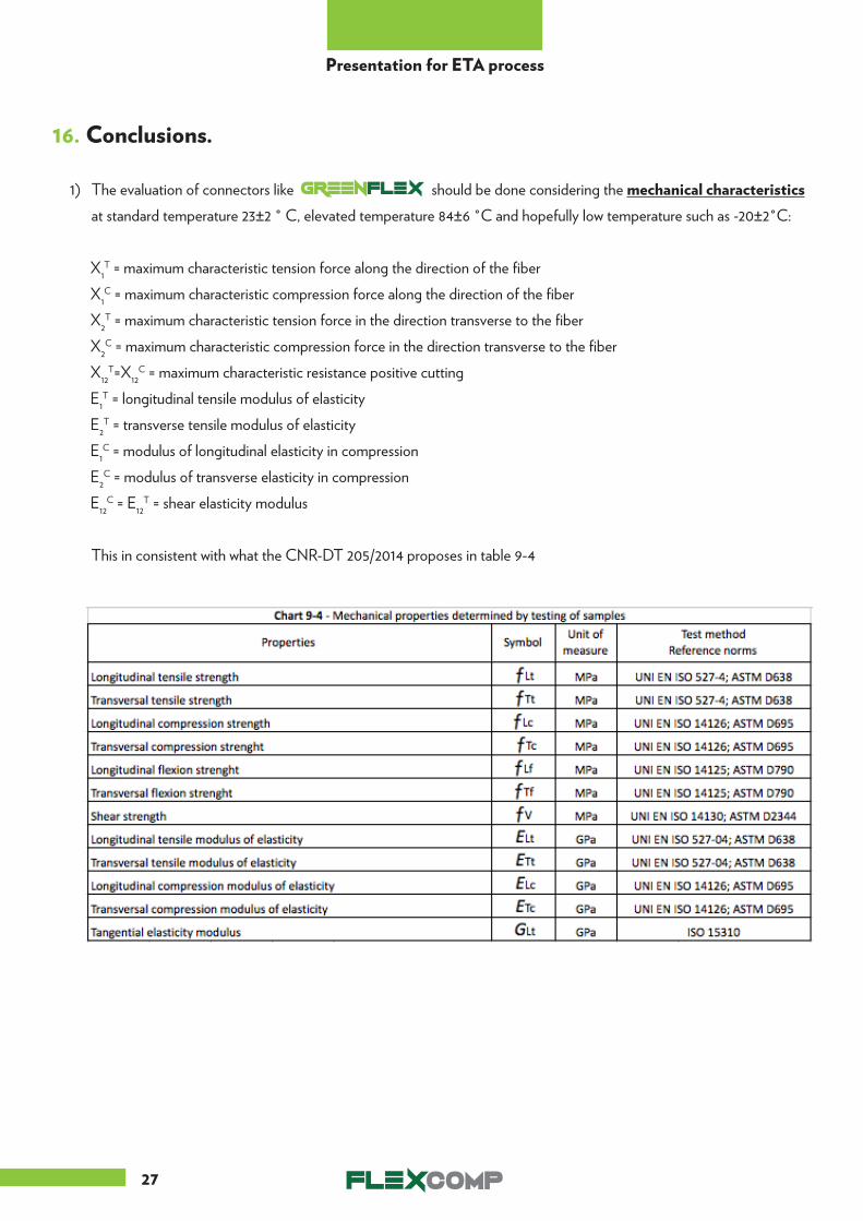
16. Conclusions.
1) The evaluation of connectors like should be done considering the mechanical characteristics at standard temperature 23±2 ° C, elevated temperature 84±6 °C and hopefully low temperature such as -20±2°C:
X1T = maximum characteristic tension force along the direction of the fiber
X1C = maximum characteristic compression force along the direction of the fiber
X2T = maximum characteristic tension force in the direction transverse to the fiber
X2C = maximum characteristic compression force in the direction transverse to the fiber
X12T=X12
C = maximum characteristic resistance positive cutting E1
T = longitudinal tensile modulus of elasticityE2
T = transverse tensile modulus of elasticityE1
C = modulus of longitudinal elasticity in compressionE2
C = modulus of transverse elasticity in compressionE12
C = E12T = shear elasticity modulus
This in consistent with what the CNR-DT 205/2014 proposes in table 9-4

28
Presentation for ETA process
2) Using a tensional / rupture verification method the w reduction coefficient for maximum admissible compression in both the main direction should be found for the minimum, maximum and average thickness insulation at the above mentioned temperature (standard temperature 23±2 ° C, elevated temperature 84±6 °C and hopefully low temperature such as -20±2°) to take in consideration the NON linear phenomena due to the composite nature (such as internal buckling of the compressed fibers) .
Using semi probabilistic state limit approach a the γ Rd = partial factor that takes into account uncertainties inherent in the resistance model should be found for the minimum, maximum and average thickness insulation at the above mentioned to take in consideration the NON linear phenomena due to the composite nature (such as internal buckling of the compressed fibers) .
3) To take in account the durability of the product should performed tests with conditioned specimens. The nature of conditioning is given by the table 2 of ICC Acceptance Criteria AC320: water at 37±2°C and alkali solution of pH = 12 at 23±2°C.
4) To take in account the variation of the loads on the pieces basically due to the thermal dilatation and shrinkage of the external layer under real condition should be verified the behavior of the material after a certain number of tension cycles.
Considering the real state of stress inside the pieces and the number of cycles during 50 years of life of the panel, should be performed a cyclic test under load control at a frequency of 2 Hz, imposing a sinusoidal cycle between a Ϭmin = Ϭmax = 40 MPa and 80 MPa, for 30000 cycles.

FOR ANY KIND OF ADDITIONAL INFORMATION ABOUT GREENFLEX PLEASE REFER TO:
SALES OFFICE:Via Crema, 70 - I - 24055 Cologno al Serio
Tel. +39 035 0667254 - Fax +39 035 0662666 - [email protected]


